ATmega128 - Hanyangccrs.hanyang.ac.kr/webpage_limdj/iot_lab/AVR.pdf · 2019-12-02 · AVR...
28
ATmega128 Introduction
Transcript of ATmega128 - Hanyangccrs.hanyang.ac.kr/webpage_limdj/iot_lab/AVR.pdf · 2019-12-02 · AVR...

ATmega128
Introduction
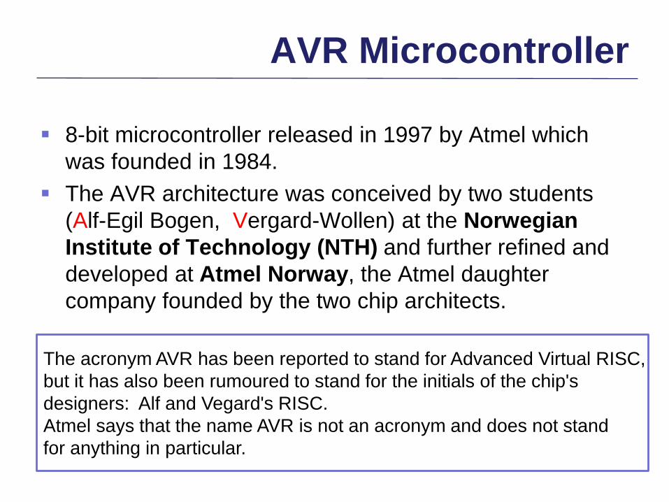
AVR Microcontroller
8-bit microcontroller released in 1997 by Atmel which
was founded in 1984.
The AVR architecture was conceived by two students
(Alf-Egil Bogen, Vergard-Wollen) at the Norwegian
Institute of Technology (NTH) and further refined and
developed at Atmel Norway, the Atmel daughter
company founded by the two chip architects.
The acronym AVR has been reported to stand for Advanced Virtual RISC,
but it has also been rumoured to stand for the initials of the chip's
designers: Alf and Vegard's RISC.
Atmel says that the name AVR is not an acronym and does not stand
for anything in particular.

AVR Microcontroller
8-bit microcontroller with 16-bit instruction bus and 8-bit
data bus.
Advanced RISC architecture, pipelined processing, low-
power, one instruction per a single clock cycle.
32 general purpose registers, Register-to-register
operation. (Other microprocessors: accumulator)
Simple addressing mode, compact code size.
Architecture designed for C.

Single Cycle Execution

Pipelined Processing
The Parallel Instruction Fetches and Instruction Executions
Single Cycle ALU Operation

Code size

AVR Microcontroller
Harvard architecture. Program memory and data
memory can be accessed simultaneously.
Internal flash memory is used for program memory. Only
data memory can be interfaced by external memory
addressing.
Internal flash memory is programmed by ISP(In-System
Programming). Endurance: 10,000 write/erase cycles.
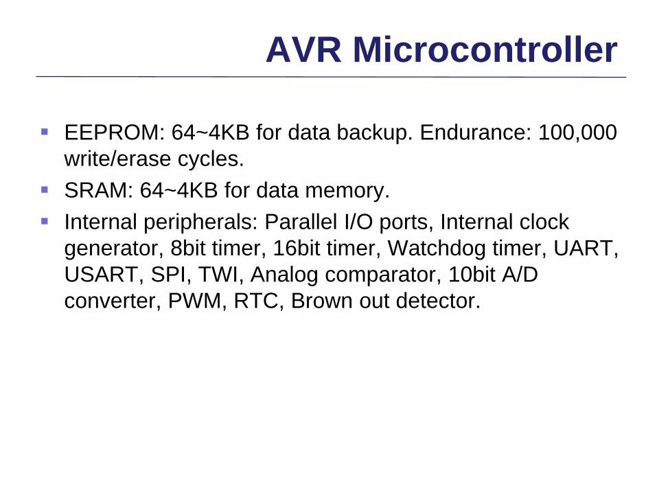
AVR Microcontroller
EEPROM: 64~4KB for data backup. Endurance: 100,000
write/erase cycles.
SRAM: 64~4KB for data memory.
Internal peripherals: Parallel I/O ports, Internal clock
generator, 8bit timer, 16bit timer, Watchdog timer, UART,
USART, SPI, TWI, Analog comparator, 10bit A/D
converter, PWM, RTC, Brown out detector.

AVR Architecture
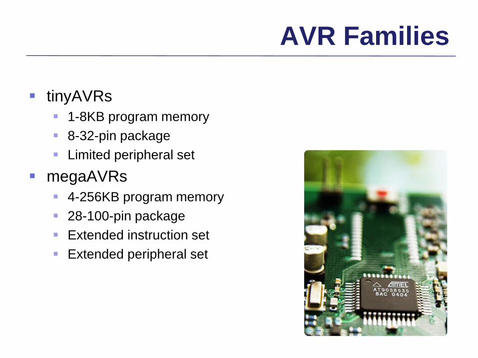
AVR Families
tinyAVRs
1-8KB program memory
8-32-pin package
Limited peripheral set
megaAVRs
4-256KB program memory
28-100-pin package
Extended instruction set
Extended peripheral set

AVR Families
XMEGA
16-256KB program memory
44-100-pin package
Extended performance features, such as DMA, “Event system”,
and cryptography support
Extended peripheral set with DACs
Application-specific AVRs
megaAVRs with special features not found on the other
members of the AVR family, such as LCD controller, USB
controller, advanced PWM, CAN etc.

ATmega128
8-bit microcontroller with high performance, low power
consumption.
Advanced RISC architecture with 16MIPS performance
at 16MHz.
133 instruction set. Most single clock cycle execution.
32 general purpose registers, many I/O control registers.
On-chip 2-cycle multiplier.
128K bytes of In-System Programmable flash memory.

ATmega128
4K bytes of EEPROM for data storage.
4K bytes of SRAM for data.
External data memory addressable up to 64 K bytes.
Internal RC oscillator circuit for system clock. Internal
circuits for external crystal or ceramic resonator.
ATmega128
Six 8bit parallel I/O ports, one 5bit parallel port.
Two 8bit Timer/Counter(0,2), two 16bit
Timer/Counter(1,3).
Two 8-bit PWM Channels, 6 PWM Channels with
Programmable Resolution from 2 to 16 Bits.
Eight channel 10bit A/D converter.
Dual Programmable Serial USARTs.
Analog comparator.

ATmega128
35 interrupt vectors including a reset vector and 8
external interrupt vectors.
Six modes for power reduction (sleep modes).
ATmega103 compatible mode.
64pin TQFP(Thin Quad Flat Package), 64pin MLF(Micro
Lead Frame).

Block Diagram of ATmega128
8bit bus for data access
(registers, SRAM,
EEPROM, I/O registers)
16bit bus for
program access

General Purpose Registers
32 general purpose 8bit registers
No accumulator. Every register works like an accumulator.
X,Y,Z : 16bit data address pointer

ATmeag128 Memory
Program memory
Flash memory: 128K bytes
Data memory
Internal SRAM: 4K bytes
External SRAM: addressable up to 64K bytes
EEPROM: 4K bytes
Program Memory
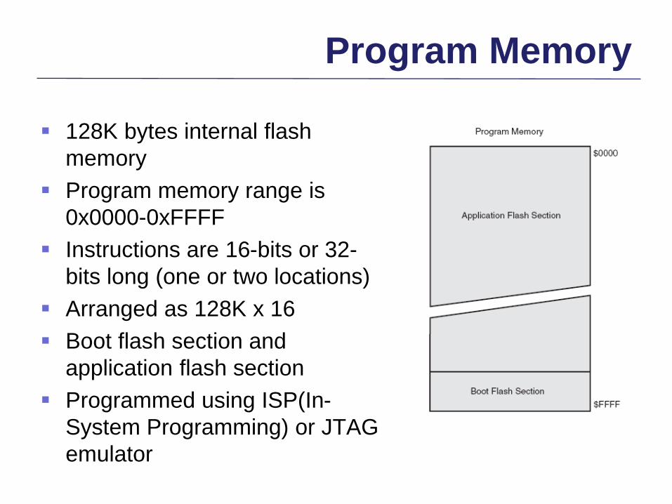
128K bytes internal flash
memory
Program memory range is
0x0000-0xFFFF
Instructions are 16-bits or 32-
bits long (one or two locations)
Arranged as 128K x 16
Boot flash section and
application flash section
Programmed using ISP(In-
System Programming) or JTAG
emulator

Data Memory
Internal SRAM
External SRAM:
addressable up to 64K
bytes of data memory
space.
Internal EEPROM:
accessed through special
registers.

External Memory Interface

8051 Accessing external code memory

Interface to 1K RAM

8051 Address decoding
0000H-1FFFH, 2000H-3FFFH,…

External SRAM Interface
Signals: A15~A8, AD7~AD0, ALE, RD’, WR’
MCUCR Register setting
External SRAM Connected to the AVR

External SRAM Interface
MCUCR : B7, B6

Address Map with 32KB External Memory

I/O device control
registers
Extended I/O registers:
new registers added to
ATmega128
I/O Registers