ATM Connections - Mauimauigateway.com/~surfer/library/ATM_connections.pdf · CHAPTER ATM...
38
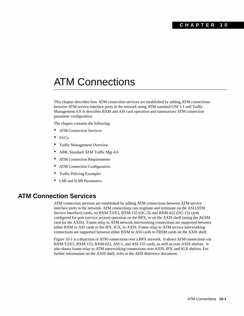
CHAPTER ATM Connections 10-1 10 ATM Connections This chapter describes how ATM connection services are established by adding ATM connections between ATM service interface ports in the network using ATM standard UNI 3.1 and Traffic Management 4.0. It describes BXM and ASI card operation and summarizes ATM connection parameter configuration The chapter contains the following: • ATM Connection Services • SVCs • Traffic Management Overview • ABR, Standard ATM Traffic Mgt 4.0 • ATM Connection Requirements • ATM Connection Configuration • Traffic Policing Examples • LMI and ILMI Parameters ATM Connection Services ATM connection services are established by adding ATM connections between ATM service interface ports in the network. ATM connections can originate and terminate on the ASI (ATM Service Interface) cards, on BXM-T3/E3, BXM-155 (OC-3), and BXM-622 (OC-12) cards configured for port (service access) operation on the BPX, or on the AXIS shelf (using the AUSM card for the AXIS). Frame relay to ATM network interworking connections are supported between either BXM or ASI cards to the IPX, IGX, or AXIS. Frame relay to ATM service interworking connections are supported between either BXM or ASI cards to FRSM cards on the AXIS shelf. Figure 10-1 is a depiction of ATM connections over a BPX network. It shows ATM connections via BXM-T3/E3, BXM-155, BXM-622, ASI-1, and ASI-155 cards, as well as over AXIS shelves. It also shows frame relay to ATM interworking connections over AXIS, IPX, and IGX shelves. For further information on the AXIS shelf, refer to the AXIS Reference document.
Transcript of ATM Connections - Mauimauigateway.com/~surfer/library/ATM_connections.pdf · CHAPTER ATM...
C H A P T E R
ATM Connections 10-1
1 0
ATM Connections
This chapter describes how ATM connection services are established by adding ATM connectionsbetween ATM service interface ports in the network using ATM standard UNI 3.1 and TrafficManagement 4.0. It describes BXM and ASI card operation and summarizes ATM connectionparameter configuration
The chapter contains the following:
• ATM Connection Services
• SVCs
• Traffic Management Overview
• ABR, Standard ATM Traffic Mgt 4.0
• ATM Connection Requirements
• ATM Connection Configuration
• Traffic Policing Examples
• LMI and ILMI Parameters
ATM Connection ServicesATM connection services are established by adding ATM connections between ATM serviceinterface ports in the network. ATM connections can originate and terminate on the ASI (ATMService Interface) cards, on BXM-T3/E3, BXM-155 (OC-3), and BXM-622 (OC-12) cardsconfigured for port (service access) operation on the BPX, or on the AXIS shelf (using the AUSMcard for the AXIS). Frame relay to ATM network interworking connections are supported betweeneither BXM or ASI cards to the IPX, IGX, or AXIS. Frame relay to ATM service interworkingconnections are supported between either BXM or ASI cards to FRSM cards on the AXIS shelf.
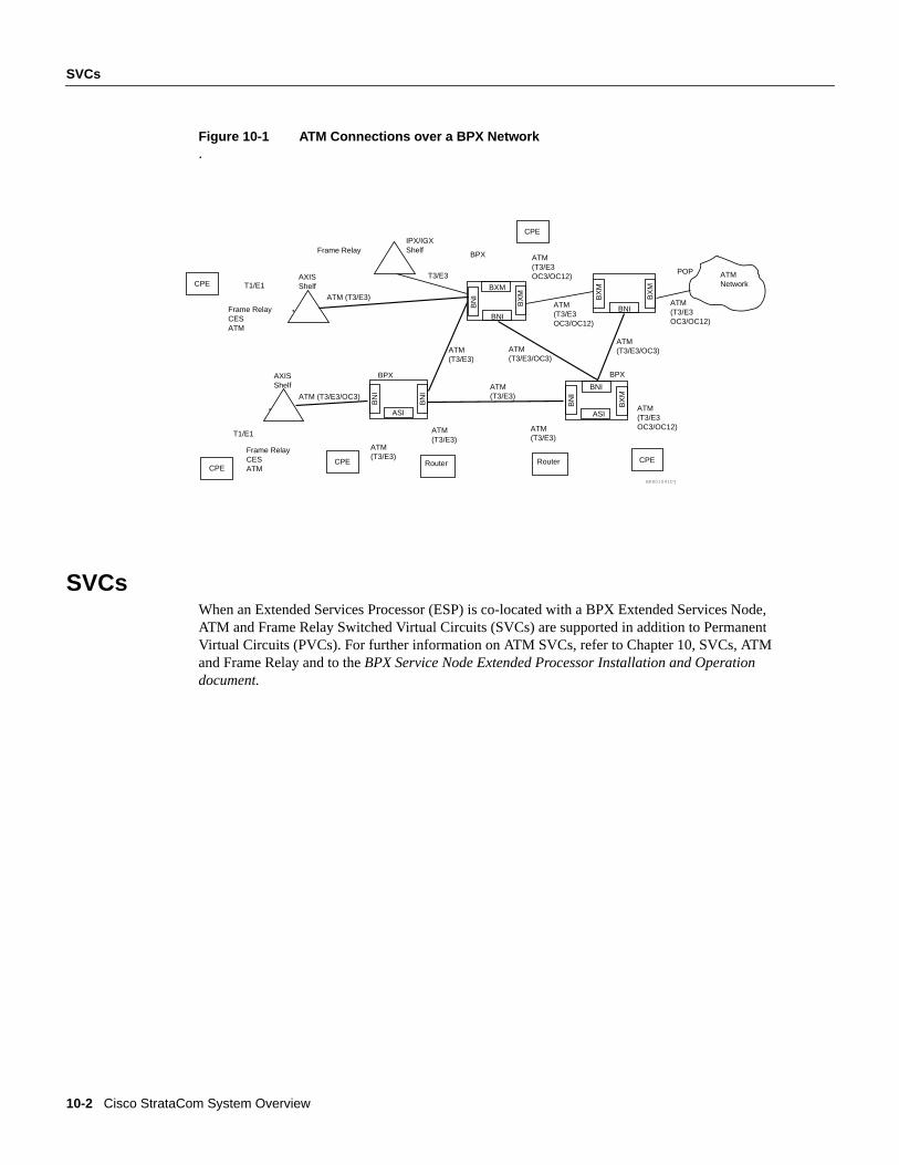
Figure 10-1 is a depiction of ATM connections over a BPX network. It shows ATM connections viaBXM-T3/E3, BXM-155, BXM-622, ASI-1, and ASI-155 cards, as well as over AXIS shelves. Italso shows frame relay to ATM interworking connections over AXIS, IPX, and IGX shelves. Forfurther information on the AXIS shelf, refer to theAXIS Referencedocument.
10-2 Cisco StrataCom System Overview
SVCs
Figure 10-1 ATM Connections over a BPX Network.
SVCsWhen an Extended Services Processor (ESP) is co-located with a BPX Extended Services Node,ATM and Frame Relay Switched Virtual Circuits (SVCs) are supported in addition to PermanentVirtual Circuits (PVCs). For further information on ATM SVCs, refer to Chapter 10, SVCs, ATMand Frame Relay and to theBPX Service Node Extended Processor Installation and Operationdocument.
BNI
BPX
BNI
ASIB
NI
BN
I
BN
I
ASI
BX
M
ATM(T3/E3OC3/OC12)
BN
I
AXISShelf
ATM(T3/E3)
ATM(T3/E3)
BPXBPX
ATM (T3/E3)
CPE
CPECPE
ATM(T3/E3OC3/OC12)
ATM(T3/E3)
BPX01041Dj
CPE
ATM(T3/E3/OC3)
AXISShelf
ATM (T3/E3/OC3)
CPERouter
BX
M
ATM(T3/E3)
Router
ATM(T3/E3)
Frame RelayCESATM
T1/E1
Frame RelayCESATM
T1/E1T3/E3
Frame RelayIPX/IGXShelf
BXM
BX
M
ATM(T3/E3OC3/OC12)
BNI
ATM(T3/E3/OC3)
ATM(T3/E3OC3/OC12)
POP
BX
M
ATMNetwork
ATM Connections 10-3
Traffic Management Overview
Traffic Management OverviewThe ATM Forum Traffic Management 4.0 Specification defines five basic traffic classes:
• CBR (Constant Bit Rate)
• rt-VBR (Real-Time Variable Bit Rate)
• nrt-VBR (Non-Real Time Variable Bit Rate)
• UBR (Unspecified Bit Rate)
• ABR (Available Bit Rate)
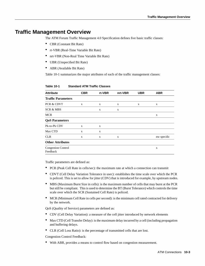
Table 10-1 summarizes the major attributes of each of the traffic management classes:
Table 10-1 Standard ATM Traffic Classes
Traffic parameters are defined as:
• PCR (Peak Cell Rate in cells/sec): the maximum rate at which a connection can transmit
• CDVT (Cell Delay Variation Tolerance in usec): establishes the time scale over which the PCRis policed. This is set to allow for jitter (CDV) that is introduced for example, by upstream nodes.
• MBS (Maximum Burst Size in cells): is the maximum number of cells that may burst at the PCRbut still be compliant. This is used to determine the BT (Burst Tolerance) which controls the timescale over which the SCR (Sustained Cell Rate) is policed.
• MCR (Minimum Cell Rate in cells per second): is the minimum cell rated contracted for deliveryby the network.
QoS (Quality of Service) parameters are defined as:
• CDV (Cell Delay Variation): a measure of the cell jitter introduced by network elements
• Max CTD (Cell Transfer Delay): is the maximum delay incurred by a cell (including propagationand buffering delays.
• CLR (Cell Loss Ratio): is the percentage of transmitted cells that are lost.
Congestion Control Feedback:
• With ABR, provides a means to control flow based on congestion measurement.
Attribute CBR rt-VBR nrt-VBR UBR ABR
Traffic Parameters
PCR & CDVT x x x x x
SCR & MBS x x
MCR x
QoS Parameters
Pk-to-Pk CDV x x
Max CTD x x
CLR x x x nw specific
Other Attributes
Congestion ControlFeedback
x
10-4 Cisco StrataCom System Overview
ABR, Standard ATM Traffic Mgt 4.0
ABR, Standard ATM Traffic Mgt 4.0
Standard ABR notes:Standard ABR uses RM (Resource Management) cells to carry feedback information back to theconnection’s source from the connection’s destination.
ABR sources periodically interleave RM cells into the data they are transmitting. These RM cells arecalled forward RM cells because they travel in the same direction as the data. At the destinationthese cells are turned around and sent back to the source as Backward RM cells.
The RM cells contain fields to increase or decrease the rate (the CI and NI fields) or set it at aparticular value (the explicit rate ER field). The intervening switches may adjust these fieldsaccording to network conditions. When the source receives an RM cell it must adjust its rate inresponse to the setting of these fields.
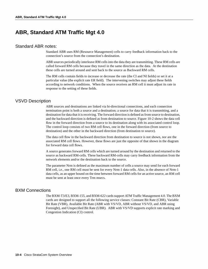
VSVD DescriptionABR sources and destinations are linked via bi-directional connections, and each connectiontermination point is both a source and a destination; a source for data that it is transmitting, and adestination for data that it is receiving. The forward direction is defined as from source to destination,and the backward direction is defined as from destination to source. Figure 10-2 shows the data cellflow in the forward direction from a source to its destination along with its associated control loop.The control loop consists of two RM cell flows, one in the forward direction (from source todestination) and the other in the backward direction (from destination to source).
The data cell flow in the backward direction from destination to source is not shown, nor are theassociated RM cell flows. However, these flows are just the opposite of that shown in the diagramfor forward data cell flows.
A source generates forward RM cells which are turned around by the destination and returned to thesource as backward RM-cells. These backward RM-cells may carry feedback information from thenetwork elements and/or the destination back to the source.
The parameter Nrm is defined as the maximum number of cells a source may send for each forwardRM cell, i.e., one RM cell must be sent for every Nrm-1 data cells. Also, in the absence of Nrm-1data cells, as an upper bound on the time between forward RM cells for an active source, an RM cellmust be sent at least once every Trm msecs.
BXM ConnectionsThe BXM-T3/E3, BXM-155, and BXM-622 cards support ATM Traffic Management 4.0. The BXMcards are designed to support all the following service classes: Constant Bit Rate (CBR), VariableBit Rate (VBR), Available Bit Rate (ABR with VS/VD, ABR without VS/VD, and ABR usingForesight), and Unspecified Bit Rate (UBR). ABR with VS/VD supports explicit rate marking andCongestion Indication (CI) control.
ATM Connections 10-5
ATM Connection Requirements
Figure 10-2 ABR VSVD Flow Control Diagram
ForeSight Congestion ControlForeSight may be used for congestion control across BPX/IGX/IPX switches for connections thathave one or both end points terminating on ASI-T3/E3 or BXM cards. The ForeSight feature is aproprietary dynamic closed-loop, rate-based, congestion management feature that yields bandwidthsavings compared to non-ForeSight equipped trunks when transmitting bursty data across cell-basednetworks. The BXM cards also support the VSVD congestion control mechanism as specified in theATM Traffic Management 4.0 standards.
ATM Connection RequirementsThere are two connection addressing modes supported. The user may enter a unique VPI/VCIaddress in which case the BPX functions as a virtual circuit switch. Or the user may enter only aVPI address in which case all circuits are switched to the same destination port and the BPXfunctions as a virtual path switch in this case. The full ATM address range for VPI and VCI issupported.Virtual Path Connections are identified by an * in the VCI field. Virtual CircuitConnections specify both the VPI and VCI fields.
The VPI and VCI fields have significance only to the local BPX, and are translated by tables in theBPX to route the connection. Connections are automatically routed by the AutoRoute feature oncethe connection endpoints are specified.
ATM connections can be added using either the StrataView Plus Connection Manager or a node’scommand line interface (CLI). Typically, the StrataView Plus Connection Manager is the preferredmethod as it has an easy to use GUI interface. The CLI may be the method of choice in some specialcases or during initial node setup for local nodes.
Forward flow data cells
Forward RM cells
Backward RM cells
Source DestinationNode
NE
Node
NE
Node
NE
RM cell control loop for forward flow data
Only the flows for forward data cells and their associated RM cell control loop are shown in this diagram. The flows for backward flow data cells (destination to source) and their associated RM cell control loop are just the opposite of that shown for the forward flow data cells.
NE = Network element S61
56
10-6 Cisco StrataCom System Overview
ATM Connection Requirements
When adding ATM connections, first the access port and access service lines connecting to thecustomer CPE need to be configured. Also, the trunks across the network need to configuredappropriately for the type of connection. Following that theaddcon command may be used to add aconnection, first specifying the service type and then the appropriate parameters for the connection.
For example, when configuring a BXM for CPE connections, the BXM is configured for port mode,a line is upped with theupln command and configured with thecnfln command. Then the associatedport is configured with thecnfport command and upped with theupport command. Following this,the ATM connections are added via theaddcon command with the syntax.
Connection RoutingATM connections for a BXM or ASI card are identified as follows:
— slot number (in the BPX shelf where the BXM or ASI is located)
— port number (one of the ATM ports on the BXM or ASI)
— Virtual Path Identifier (VPI)
— Virtual Circuit Identifier (VCI) – (* for virtual path connections).
The slot and port are related to the BPX hardware. Virtual path connections (VPCs) are identified bya “*” for the VCI field. Virtual circuit connections (VCCs) are identified by both a VPI and VCI field.
Connections added to the network are automatically routed once the end points are specified. ThisAutoRoute feature is standard with all BPX, IGX, and IPX nodes. The network automaticallydetects trunk failures and routes connections around the failures.
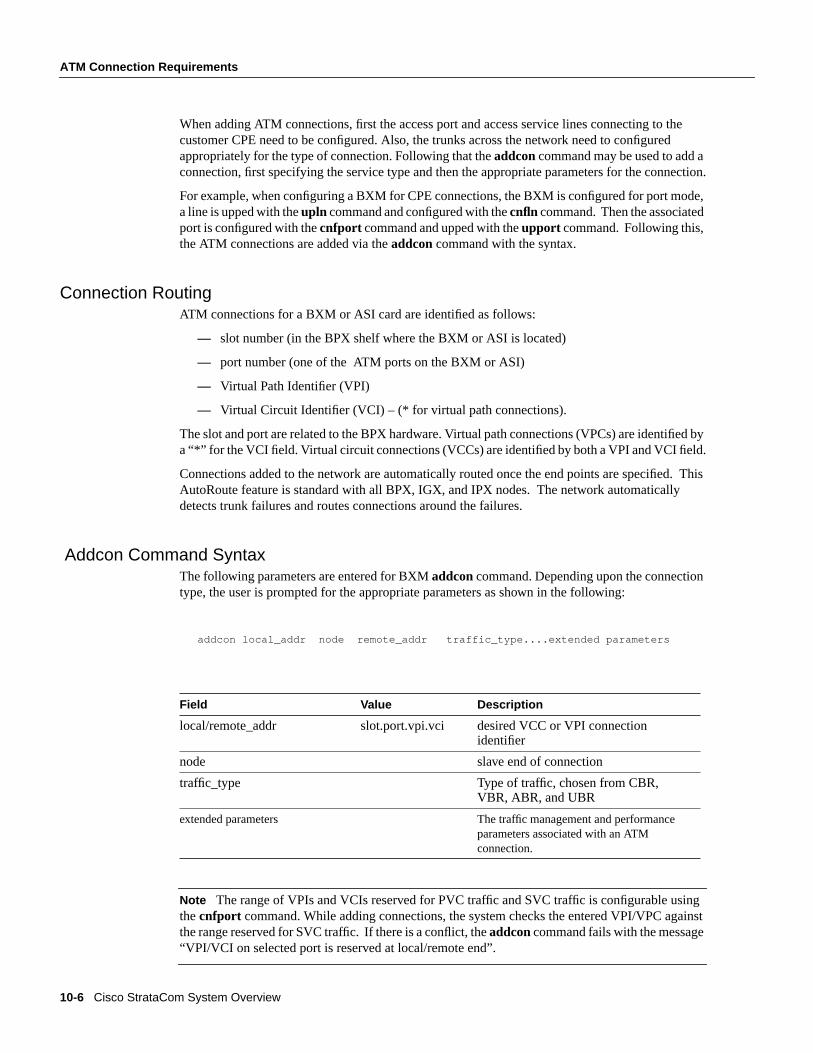
Addcon Command SyntaxThe following parameters are entered for BXMaddcon command. Depending upon the connectiontype, the user is prompted for the appropriate parameters as shown in the following:
addcon local_addr node remote_addr traffic_type....extended parameters
Note The range of VPIs and VCIs reserved for PVC traffic and SVC traffic is configurable usingthecnfport command. While adding connections, the system checks the entered VPI/VPC againstthe range reserved for SVC traffic. If there is a conflict, theaddcon command fails with the message“VPI/VCI on selected port is reserved at local/remote end”.
Field Value Description
local/remote_addr slot.port.vpi.vci desired VCC or VPI connectionidentifier
node slave end of connection
traffic_type Type of traffic, chosen from CBR,VBR, ABR, and UBR
extended parameters The traffic management and performanceparameters associated with an ATMconnection.
ATM Connections 10-7
ATM Connection Configuration
ATM Connection ConfigurationThe following figures and tables describe the parameters used to configure ATM connections:
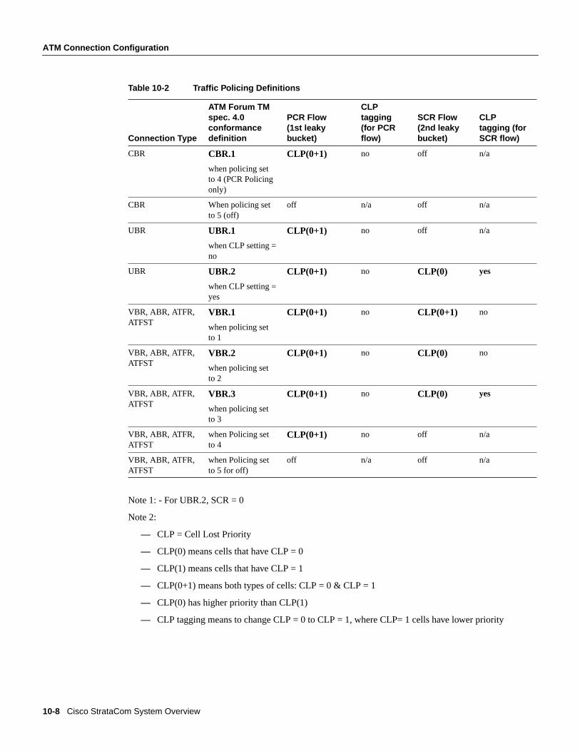
• Table 10-2, Traffic Policing Definitions.
— This table describes the policing options that may be selected for ATM connection types:CBR, UBR, and VBR. The policing options for ABR are the same as for VBR.
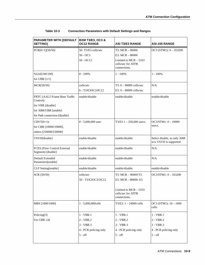
• Table 10-3, Connection Parameter Default Settings and Ranges
— This table specifies the ATM connection parameter ranges and defaults. Not all theparameters are used for every connection type. When adding connections, you are promptedfor the applicable parameters, as specified in the prompt sequence diagrams included inFigure 10-3 through Figure 10-10.
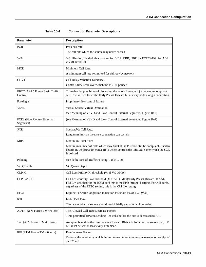
• Table 10-4, Connection Parameter Descriptions
— This table defines the connection parameters listed in Table 10-3.
The following figures list the connection parameters in the same sequence as they are entered whena connection is added:
• Figure 10-3, CBR Connection Prompt Sequence
• Figure 10-4, VBR Connection Prompt Sequence
• Figure 10-5, ATFR Connection Prompt Sequence
• Figure 10-6, ABR Standard Connection Prompt Sequence
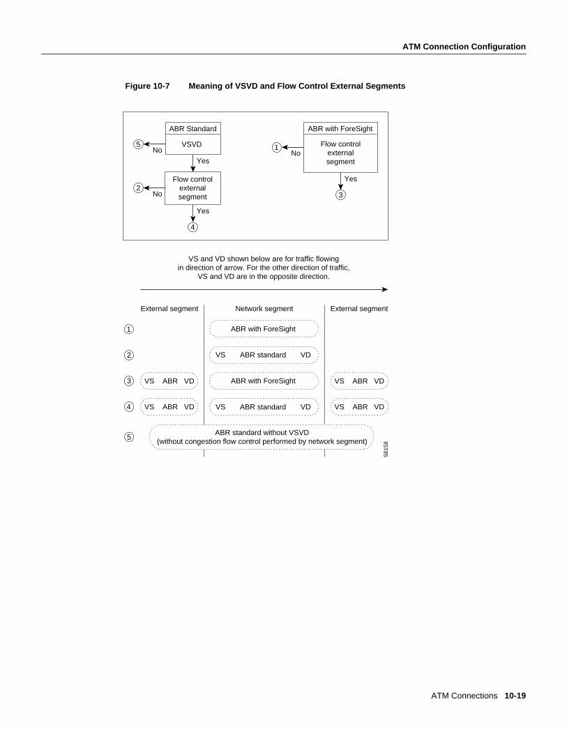
The following figure shows the VSVD network segment and external segment options availablewhen ABR Standard or ABR ForeSight is selected. ForeSight congestion control is useful when bothends of a connection do not terminate on BXM cards. At present, FCES (Flow Control ExternalSegment) as shown in Figure 10-7 is not available for ABR with ForeSight.
• Figure 10-7, Meaning of VSVD and Flow Connection External Segments
The following figures list the connection parameters in the same sequence as they are entered whena connection is added:
• Figure 10-8, ABR ForeSight Connection Prompt Sequence
• Figure 10-9, ATFST Connection Prompt Sequence
• Figure 10-10, UBR Connection Prompt Sequence
10-8 Cisco StrataCom System Overview
ATM Connection Configuration
Table 10-2 Traffic Policing Definitions
Note 1: - For UBR.2, SCR = 0
Note 2:
— CLP = Cell Lost Priority
— CLP(0) means cells that have CLP = 0
— CLP(1) means cells that have CLP = 1
— CLP(0+1) means both types of cells: CLP = 0 & CLP = 1
— CLP(0) has higher priority than CLP(1)
— CLP tagging means to change CLP = 0 to CLP = 1, where CLP= 1 cells have lower priority
Connection Type
ATM Forum TMspec. 4.0conformancedefinition
PCR Flow(1st leakybucket)
CLPtagging(for PCRflow)
SCR Flow(2nd leakybucket)
CLPtagging (forSCR flow)
CBR CBR.1
when policing setto 4 (PCR Policingonly)
CLP(0+1) no off n/a
CBR When policing setto 5 (off)
off n/a off n/a
UBR UBR.1
when CLP setting =no
CLP(0+1) no off n/a
UBR UBR.2
when CLP setting =yes
CLP(0+1) no CLP(0) yes
VBR, ABR, ATFR,ATFST
VBR.1
when policing setto 1
CLP(0+1) no CLP(0+1) no
VBR, ABR, ATFR,ATFST
VBR.2
when policing setto 2
CLP(0+1) no CLP(0) no
VBR, ABR, ATFR,ATFST
VBR.3
when policing setto 3
CLP(0+1) no CLP(0) yes
VBR, ABR, ATFR,ATFST
when Policing setto 4
CLP(0+1) no off n/a
VBR, ABR, ATFR,ATFST
when Policing setto 5 for off)
off n/a off n/a
ATM Connections 10-9
ATM Connection Configuration
Table 10-3 Connection Parameters with Default Settings and Ranges
PARAMETER WITH [DEFAULTSETTING]
BXM T3/E3, OC3 &OC12 RANGE ASI T3/E3 RANGE ASI-155 RANGE
PCR(0+1)[50/50] 50- T3/E3 cells/sec
50 - OC3
50 - OC12
T3: MCR – 96000
E3: MCR – 80000
Limited to MCR – 5333cells/sec for ATFRconnections.
OC3 (STM1): 0 – 353200
%Util[100/100]
for UBR [1/1]
0 - 100% 1 - 100% 1 - 100%
MCR[50/50] cells/sec
6 - T3/E3OC3/0C12
T3: 0 – 96000 cells/sec
E3: 0 – 80000 cells/sec
N/A
FBTC (AAL5 Frame Base TrafficControl):
for VBR [disable]
for ABR/UBR [enable]
for Path connection [disable]
enable/disable enable/disable enable/disable
CDVT(0+1):
for CBR [10000/10000],
others [250000/250000]
0 - 5,000,000 usec T3/E3 1 – 250,000 usecs. OC3/STM1: 0 – 10000usecs.
VSVD[disable] enable/disable enable/disable Select disable, as only ABRw/o VSVD is supported.
FCES (Flow Control ExternalSegment) [disable]
enable/disable enable/disable N/A
Default ExtendedParameters[enable]
enable/disable enable/disable N/A
CLP Setting[enable] enable/disable enable/disable enable/disable
SCR [50/50] cells/sec
50 - T3/E3OC3/OC12
T3: MCR – 96000:T3
E3: MCR – 80000: E3
Limited to MCR – 5333cells/sec for ATFRconnections.
OC3/STM1: 0 – 353200
MBS [1000/1000] 1 - 5,000,000cells T3/E3: 1 – 24000 cells OC3 (STM1): 10 – 1000cells
Policing[3]
For CBR: [4]
1 - VBR.1
2 - VBR.2
3 - VBR.3
4 - PCR policing only
5 - off
1 - VBR.1
2 - VBR.2
3 - VBR.3
4 - PCR policing only
5 - off
1 - VBR.1
2 - VBR.2
3 - VBR.3
4 - PCR policing only
5 - off

10-10 Cisco StrataCom System Overview
ATM Connection Configuration
ICR:
max[MCR, PCR/10]
MCR - PCR cells/sec MCR - PCR cells/sec N/A
ADTF[1000] 62 - 8000 msec 1000 – 255000 msecs. N/A
Trm[100] ABR std: 1 - 100 msec
ABR (FST): 3 - 255 msec
20 – 250 msecs. N/A
VC QDepth [16000/16000]
For ATFR/ATFST [1366/1366]
0 - 64140 cells Applies to T3/E3 onlyABR: 1 – 64000 cellsATFR: 1 – 1366 cells
ATFR: 1 – 1366 cells
CLP Hi [80/80] 0 - 100% 0 – 100% N/A
CLP Lo/EPD [35/35] 0 - 100% 0 – 100% N/A
EFCI [30/30]
For ATFR/ATFST [100/100]
0 - 100% 0 – 100% 0 - 100%
RIF:
For ForeSight:
max[PCR/128, 10]
For ABR STD[128]
If ForeSight, then inabsolute (0 - PCR)
If ABR then 2n
(1 - 32768)
If ForeSight, then inabsolute (0 – PCR)
If ABR, then 2n
(1 – 32768)
N/A
RDF:
For ForeSight [93]
For ABR STD [16]
If ForeSight, then %
(0% - 100%)
If ABR then 2n
(1 - 32768)
If ForeSight, then %
(0% – 100%)
If ABR, then 2n
(1 – 32768)
N/A
Nrm[32], BXM only 2 - 256 cells N/A N/A
FRTT[0], BXM only 0 - 16700 msec N/A N/A
TBE[1,048,320], BXM only 0 - 1,048,320 cells
(different max range fromTM spec. but limited byfirmware for CRM(4095only) whereCRM=TBE/Nrm
N/A N/A
IBS[0/0] 0 - 24000 cells T3/E3 ABR: 0 - 24000 cells
ATFR: 1 - 107 cells
0 - 999 cells
PARAMETER WITH [DEFAULTSETTING]
BXM T3/E3, OC3 &OC12 RANGE ASI T3/E3 RANGE ASI-155 RANGE
ATM Connections 10-11
ATM Connection Configuration
Table 10-4 Connection Parameter Descriptions
Parameter Description
PCR Peak cell rate:
The cell rate which the source may never exceed
%Util % Utilization; bandwidth allocation for: VBR, CBR, UBR it’s PCR*%Util, for ABRit’s MCR*%Util
MCR Minimum Cell Rate:
A minimum cell rate committed for delivery by network
CDVT Cell Delay Variation Tolerance:
Controls time scale over which the PCR is policed
FBTC (AAL5 Frame Basic TrafficControl)
To enable the possibility of discarding the whole frame, not just one non-compliantcell. This is used to set the Early Packet Discard bit at every node along a connection.
ForeSight Proprietary flow control feature
VSVD Virtual Source Virtual Destination:
(see Meaning of VSVD and Flow Control External Segments, Figure 10-7)
FCES (Flow Control ExternalSegments)
(see Meaning of VSVD and Flow Control External Segments, Figure 10-7)
SCR Sustainable Cell Rate:
Long term limit on the rate a connection can sustain
MBS Maximum Burst Size:
Maximum number of cells which may burst at the PCR but still be compliant. Used todetermine the Burst Tolerance (BT) which controls the time scale over which the SCRis policed
Policing (see definitions of Traffic Policing, Table 10-2)
VC QDepth VC Queue Depth
CLP Hi Cell Loss Priority Hi threshold (% of VC QMax)
CLP Lo/EPD Cell Loss Priority Low threshold (% of VC QMax)/Early Packet Discard. If AAL5FBTC = yes, then for the BXM card this is the EPD threshold setting. For ASI cards,regardless of the FBTC setting, this is the CLP Lo setting.
EFCI Explicit Forward Congestion Indication threshold (% of VC QMax)
ICR Initial Cell Rate:
The rate at which a source should send initially and after an idle period
ADTF (ATM Forum TM 4.0 term) The Allowed-Cell-Rate Decrease Factor:
Time permitted between sending RM-cells before the rate is decreased to ICR
Trm (ATM Forum TM 4.0 term) An upper bound on the time between forward RM-cells for an active source, i.e., RMcell must be sent at least every Trm msec
RIF (ATM Forum TM 4.0 term) Rate Increase Factor:
Controls the amount by which the cell transmission rate may increase upon receipt ofan RM cell
10-12 Cisco StrataCom System Overview
ATM Connection Configuration
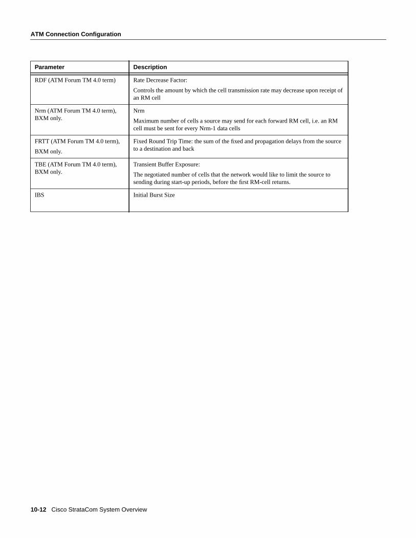
RDF (ATM Forum TM 4.0 term) Rate Decrease Factor:
Controls the amount by which the cell transmission rate may decrease upon receipt ofan RM cell
Nrm (ATM Forum TM 4.0 term),BXM only.
Nrm
Maximum number of cells a source may send for each forward RM cell, i.e. an RMcell must be sent for every Nrm-1 data cells
FRTT (ATM Forum TM 4.0 term),
BXM only.
Fixed Round Trip Time: the sum of the fixed and propagation delays from the sourceto a destination and back
TBE (ATM Forum TM 4.0 term),BXM only.
Transient Buffer Exposure:
The negotiated number of cells that the network would like to limit the source tosending during start-up periods, before the first RM-cell returns.
IBS Initial Burst Size
Parameter Description
ATM Connections 10-13
ATM Connection Configuration
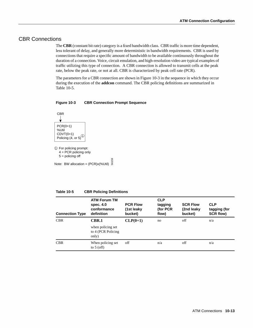
CBR ConnectionsTheCBR (constant bit rate) category is a fixed bandwidth class. CBR traffic is more time dependent,less tolerant of delay, and generally more deterministic in bandwidth requirements. CBR is used byconnections that require a specific amount of bandwidth to be available continuously throughout theduration of a connection. Voice, circuit emulation, and high-resolution video are typical examples oftraffic utilizing this type of connection. A CBR connection is allowed to transmit cells at the peakrate, below the peak rate, or not at all. CBR is characterized by peak cell rate (PCR).
The parameters for a CBR connection are shown in Figure 10-3 in the sequence in which they occurduring the execution of theaddcon command. The CBR policing definitions are summarized inTable 10-5.
Figure 10-3 CBR Connection Prompt Sequence
Table 10-5 CBR Policing Definitions
Connection Type
ATM Forum TMspec. 4.0conformancedefinition
PCR Flow(1st leakybucket)
CLPtagging(for PCRflow)
SCR Flow(2nd leakybucket)
CLPtagging (forSCR flow)
CBR CBR.1
when policing setto 4 (PCR Policingonly)
CLP(0+1) no off n/a
CBR When policing setto 5 (off)
off n/a off n/a
CBR
PCR(0+1)%UtilCDVT(0+1)Policing (4, or 5)
For policing prompt: 4 = PCR policing only 5 = policing off
Note: BW allocation = (PCR)x(%Util) S61
59
1
1
10-14 Cisco StrataCom System Overview
ATM Connection Configuration
VBR and ATFR Connections
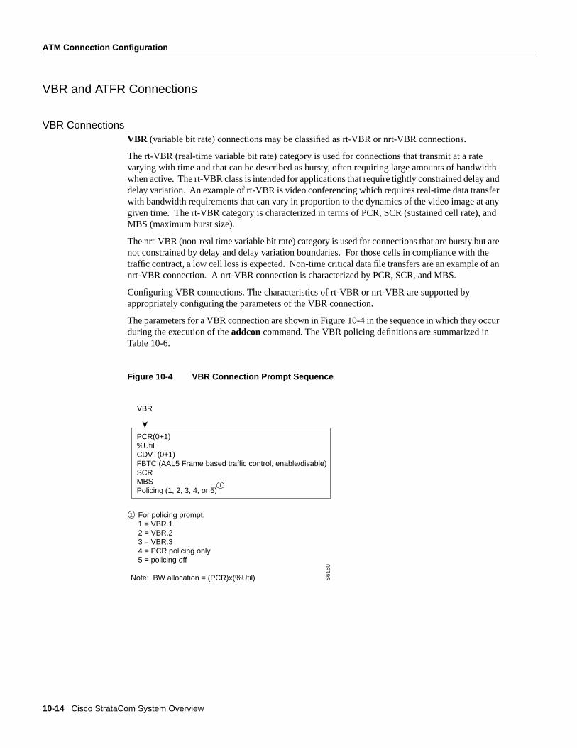
VBR ConnectionsVBR (variable bit rate) connections may be classified as rt-VBR or nrt-VBR connections.
The rt-VBR (real-time variable bit rate) category is used for connections that transmit at a ratevarying with time and that can be described as bursty, often requiring large amounts of bandwidthwhen active. The rt-VBR class is intended for applications that require tightly constrained delay anddelay variation. An example of rt-VBR is video conferencing which requires real-time data transferwith bandwidth requirements that can vary in proportion to the dynamics of the video image at anygiven time. The rt-VBR category is characterized in terms of PCR, SCR (sustained cell rate), andMBS (maximum burst size).
The nrt-VBR (non-real time variable bit rate) category is used for connections that are bursty but arenot constrained by delay and delay variation boundaries. For those cells in compliance with thetraffic contract, a low cell loss is expected. Non-time critical data file transfers are an example of annrt-VBR connection. A nrt-VBR connection is characterized by PCR, SCR, and MBS.
Configuring VBR connections. The characteristics of rt-VBR or nrt-VBR are supported byappropriately configuring the parameters of the VBR connection.
The parameters for a VBR connection are shown in Figure 10-4 in the sequence in which they occurduring the execution of theaddcon command. The VBR policing definitions are summarized inTable 10-6.
Figure 10-4 VBR Connection Prompt Sequence
VBR
PCR(0+1)%UtilCDVT(0+1)FBTC (AAL5 Frame based traffic control, enable/disable)SCRMBSPolicing (1, 2, 3, 4, or 5)
For policing prompt: 1 = VBR.1 2 = VBR.2 3 = VBR.3 4 = PCR policing only 5 = policing off
Note: BW allocation = (PCR)x(%Util) S61
60
1
1
ATM Connections 10-15
ATM Connection Configuration
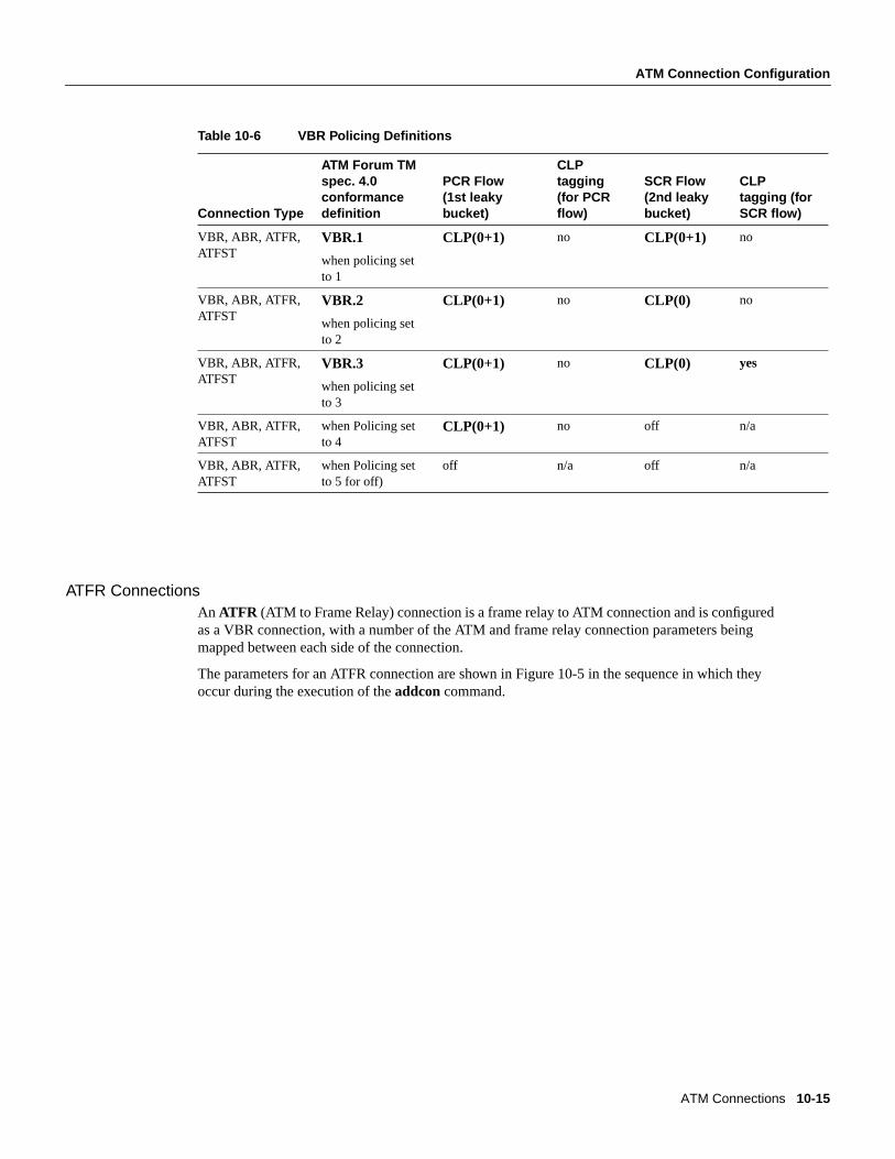
Table 10-6 VBR Policing Definitions
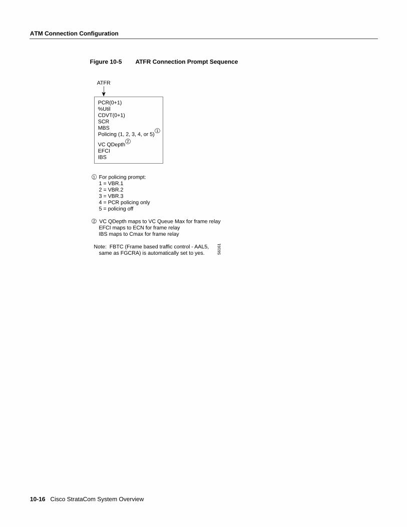
ATFR ConnectionsAn ATFR (ATM to Frame Relay) connection is a frame relay to ATM connection and is configuredas a VBR connection, with a number of the ATM and frame relay connection parameters beingmapped between each side of the connection.
The parameters for an ATFR connection are shown in Figure 10-5 in the sequence in which theyoccur during the execution of theaddcon command.
Connection Type
ATM Forum TMspec. 4.0conformancedefinition
PCR Flow(1st leakybucket)
CLPtagging(for PCRflow)
SCR Flow(2nd leakybucket)
CLPtagging (forSCR flow)
VBR, ABR, ATFR,ATFST
VBR.1
when policing setto 1
CLP(0+1) no CLP(0+1) no
VBR, ABR, ATFR,ATFST
VBR.2
when policing setto 2
CLP(0+1) no CLP(0) no
VBR, ABR, ATFR,ATFST
VBR.3
when policing setto 3
CLP(0+1) no CLP(0) yes
VBR, ABR, ATFR,ATFST
when Policing setto 4
CLP(0+1) no off n/a
VBR, ABR, ATFR,ATFST
when Policing setto 5 for off)
off n/a off n/a
10-16 Cisco StrataCom System Overview
ATM Connection Configuration
Figure 10-5 ATFR Connection Prompt Sequence
ATFR
PCR(0+1)%UtilCDVT(0+1)SCRMBSPolicing (1, 2, 3, 4, or 5)
VC QDepthEFCIIBS
For policing prompt: 1 = VBR.1 2 = VBR.2 3 = VBR.3 4 = PCR policing only 5 = policing off
VC QDepth maps to VC Queue Max for frame relay EFCI maps to ECN for frame relay IBS maps to Cmax for frame relay Note: FBTC (Frame based traffic control - AAL5, same as FGCRA) is automatically set to yes. S
6161
1
1
2
2
ATM Connections 10-17
ATM Connection Configuration
Release 8.4 ABR NotesThe term ABR is used to specify one of the following:
• ABR standard without VSVD (This is ABR standard without congestion flow control.)
— Supported by BXM, ASI-T3 (& ASI-E3), and ASI OC3 cards.
• ABR standard with VSVD. (This is ABR standard with congestion flow control as specified bythe ATM Traffic Management, Version 4.0)
— Also, referred to as ABR.1
— Supported only by BXM cards
— Feature must be ordered.
• ABR with ForeSight congestion control
— Also, referred to as ABR.FST
— Supported by BXM and ASI-T3 (& ASI-E3) cards
— Feature must be ordered.
ABR and ATFST Connections
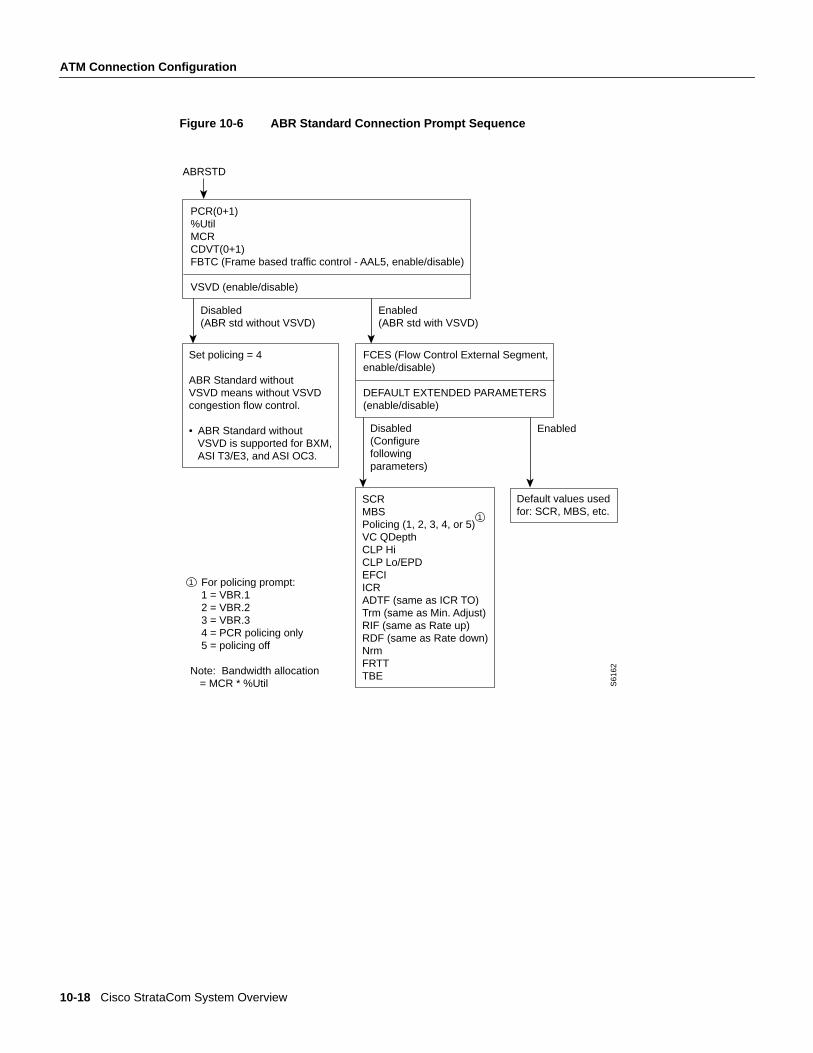
ABR ConnectionsTheABR (available bit rate) category utilizes a congestion flow control mechanism to controlcongestion during busy periods and to take advantage of available bandwidth during less busyperiods. The congestion flow control mechanism provides feedback to control the connections flowrate through the network in response to network bandwidth availability. The ABR service is notrestricted by bounding delay or delay variation and is not intended to support real-time connections.ABR is characterized by: PCR and MCR.
Policing for ABR connections is the same as for VBR connections which are summarized inTable 10-6.
The ABR connections are configured as either ABR Standard (ABRSTD) connections or as ABRForeSight (ABRFST) connections.
The parameters for an ABRSTD connection are shown in Figure 10-6 in the sequence in which theyoccur during the execution of theaddcon command.
The ABRSTD connection supports all the features of ATM Standards Traffic Management 4.0including VSVD congestion flow control.
VSVD and flow control with external segments are shown in Figure 10-7.
10-18 Cisco StrataCom System Overview
ATM Connection Configuration
Figure 10-6 ABR Standard Connection Prompt Sequence
ABRSTD
PCR(0+1)%UtilMCRCDVT(0+1)FBTC (Frame based traffic control - AAL5, enable/disable)
VSVD (enable/disable)
For policing prompt: 1 = VBR.1 2 = VBR.2 3 = VBR.3 4 = PCR policing only 5 = policing off
Note: Bandwidth allocation = MCR * %Util S
6162
Disabled(ABR std without VSVD)
Enabled(ABR std with VSVD)
Set policing = 4
ABR Standard without VSVD means without VSVDcongestion flow control.
• ABR Standard without VSVD is supported for BXM, ASI T3/E3, and ASI OC3.
FCES (Flow Control External Segment,enable/disable)
DEFAULT EXTENDED PARAMETERS(enable/disable)
Disabled(Configurefollowingparameters)
Enabled
SCRMBSPolicing (1, 2, 3, 4, or 5)VC QDepthCLP HiCLP Lo/EPDEFCIICRADTF (same as ICR TO)Trm (same as Min. Adjust)RIF (same as Rate up)RDF (same as Rate down)NrmFRTTTBE
Default values used for: SCR, MBS, etc.
1
1
ATM Connections 10-19
ATM Connection Configuration
Figure 10-7 Meaning of VSVD and Flow Control External Segments
VS and VD shown below are for traffic flowing in direction of arrow. For the other direction of traffic,
VS and VD are in the opposite direction.
External segment Network segment External segment
1
2
3
4
5
5
ABR with ForeSight
VS ABR standard VD
VS ABR standard VD
ABR with ForeSightVS ABR VD
VS ABR VD
VS ABR VD
VS ABR VD
ABR standard without VSVD(without congestion flow control performed by network segment)
ABR Standard
VSVDNo
2No
Yes
1
ABR with ForeSight
No
Yes
Yes
Flow controlexternal segment
4
Flow controlexternal segment
3
S61
58
10-20 Cisco StrataCom System Overview
ATM Connection Configuration
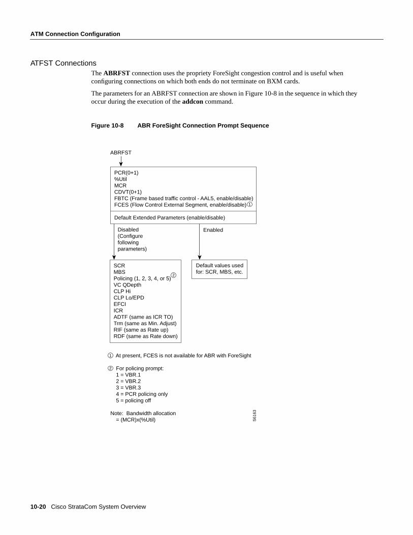
ATFST ConnectionsTheABRFST connection uses the propriety ForeSight congestion control and is useful whenconfiguring connections on which both ends do not terminate on BXM cards.
The parameters for an ABRFST connection are shown in Figure 10-8 in the sequence in which theyoccur during the execution of theaddcon command.
Figure 10-8 ABR ForeSight Connection Prompt Sequence
ABRFST
PCR(0+1)%UtilMCRCDVT(0+1)FBTC (Frame based traffic control - AAL5, enable/disable)FCES (Flow Control External Segment, enable/disable)
Default Extended Parameters (enable/disable)
At present, FCES is not available for ABR with ForeSight
For policing prompt: 1 = VBR.1 2 = VBR.2 3 = VBR.3 4 = PCR policing only 5 = policing off
Note: Bandwidth allocation = (MCR)x(%Util) S
6163
Enabled
Default values usedfor: SCR, MBS, etc.
Disabled(Configurefollowingparameters)
SCRMBSPolicing (1, 2, 3, 4, or 5)VC QDepthCLP HiCLP Lo/EPDEFCIICRADTF (same as ICR TO)Trm (same as Min. Adjust)RIF (same as Rate up)RDF (same as Rate down)
1
2
2
1
ATM Connections 10-21
ATM Connection Configuration
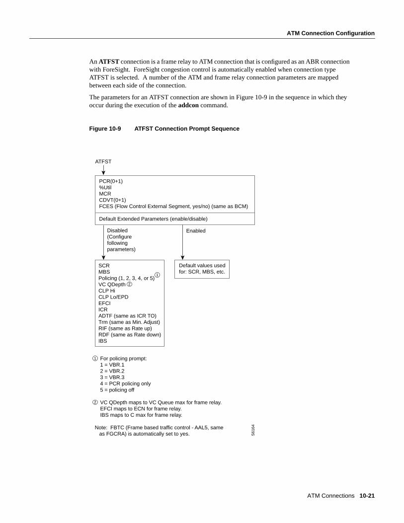
An ATFST connection is a frame relay to ATM connection that is configured as an ABR connectionwith ForeSight. ForeSight congestion control is automatically enabled when connection typeATFST is selected. A number of the ATM and frame relay connection parameters are mappedbetween each side of the connection.
The parameters for an ATFST connection are shown in Figure 10-9 in the sequence in which theyoccur during the execution of theaddcon command.
Figure 10-9 ATFST Connection Prompt Sequence
ATFST
PCR(0+1)%UtilMCRCDVT(0+1)FCES (Flow Control External Segment, yes/no) (same as BCM)
Default Extended Parameters (enable/disable)
For policing prompt: 1 = VBR.1 2 = VBR.2 3 = VBR.3 4 = PCR policing only 5 = policing off
VC QDepth maps to VC Queue max for frame relay. EFCI maps to ECN for frame relay. IBS maps to C max for frame relay.
Note: FBTC (Frame based traffic control - AAL5, same as FGCRA) is automatically set to yes. S
6164
Enabled
Default values usedfor: SCR, MBS, etc.
Disabled (Configurefollowingparameters)
SCRMBSPolicing (1, 2, 3, 4, or 5)VC QDepthCLP HiCLP Lo/EPDEFCIICRADTF (same as ICR TO)Trm (same as Min. Adjust)RIF (same as Rate up)RDF (same as Rate down)IBS
1
2
1
2
10-22 Cisco StrataCom System Overview
ATM Connection Configuration
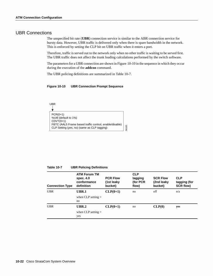
UBR ConnectionsThe unspecified bit rate (UBR) connection service is similar to the ABR connection service forbursty data. However, UBR traffic is delivered only when there is spare bandwidth in the network.This is enforced by setting the CLP bit on UBR traffic when it enters a port.
Therefore, traffic is served out to the network only when no other traffic is waiting to be served first.The UBR traffic does not affect the trunk loading calculations performed by the switch software.
The parameters for a UBR connection are shown in Figure 10-10 in the sequence in which they occurduring the execution of theaddcon command.
The UBR policing definitions are summarized in Table 10-7.
Figure 10-10 UBR Connection Prompt Sequence
Table 10-7 UBR Policing Definitions
Connection Type
ATM Forum TMspec. 4.0conformancedefinition
PCR Flow(1st leakybucket)
CLPtagging(for PCRflow)
SCR Flow(2nd leakybucket)
CLPtagging (forSCR flow)
UBR UBR.1
when CLP setting =no
CLP(0+1) no off n/a
UBR UBR.2
when CLP setting =yes
CLP(0+1) no CLP(0) yes
UBR
PCR(0+1)%Util (default to 1%)CDVT(0+1)FBTC (AAL5 Frame based traffic control, enable/disable)CLP Setting (yes, no) (same as CLP tagging)
S61
65

ATM Connections 10-23
Traffic Policing Examples
Traffic Policing ExamplesTraffic Policing, also known as Usage Parameter Control (UPC), is implemented using either anATM Forum single or dual-leaky bucket algorithm. The buckets represent a GCRA (Generic CellRate Algorithm) defined by two parameters:
• Rate (where I, expected arrival interval is defined as 1/Rate)
• Deviation (L)
If the cells are clumped too closely together, they are non-compliant and are tagged or discarded asapplicable. If other cells arrive on time or after their expected arrival time, they are compliant, butthree is no accrued credit.
Dual-Leaky Bucket (An Analogy)A GCRA viewpoint is as follows:
• For a stream of cells in an ATM connection, the cell compliance is based on the theoretical arrivaltime (TAT).
• The next TAT should be the time of arrival of the last compliant cell plus the expected arrivalinterval (I) where I = 1/rate.
• If the next cell arrives before the new TAT, it must arrive no earlier than new TAT - CDVT to becompliant.
• If the next cell arrives after the new TAT, it is compliant, but there is no accrued credit.
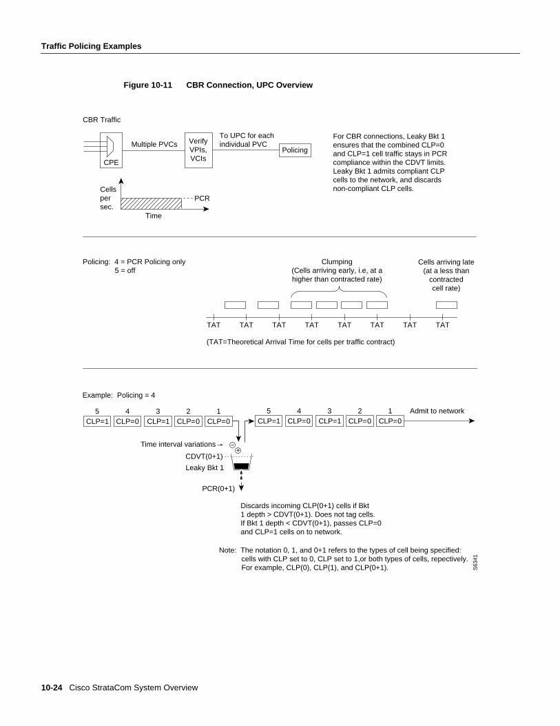
CBR Traffic Policing ExamplesCBR traffic is expected to be at a constant bit rate, have low jitter, and is configured for a constantrate equal to Peak Cell Rate (PCR). The connection is expected to be always at peak rate.
When a connection is added, a VPI.VCI address is assigned, and the UPC parameters are configuredfor the connection. For each cell in an ATM stream seeking admission to the network, the VPI.VCIaddresses are verified and each cell is checked for compliance with the UPC parameters. The CBRcells are not enqueued, but are processed by the policing function and then sent to the network unlessdiscarded.
For CBR, traffic policing is based on:
• Bucket 1
— PCR(0+1), Peak Cell Rate
— CDVT(0+1), Cell Delay Variation
The CBR connection may be configured with policing selected as either 4 or 5. With policing set to5, there is no policing. With policing set to 4, there is single leaky bucket PCR policing as shown inFigure 10-11. The single leaky bucket polices the PCR compliance of all cells seeking admission tothe network, both those with CLP = 0 and those with CLP =1. Cells seeking admission to thenetwork with CLP set equal to 1 may have either encountered congestion along the user’s networkor may have lower importance to the user and have been designated as eligible for discard in the casecongestion is encountered. If the bucket depth CDVT (0+1) limit is exceeded, it discards all cellsseeking admission. It does not tag cells. If leaky bucket 1 is not full, all cells (CLP =0 and CLP=1)are admitted to the network.
10-24 Cisco StrataCom System Overview
Traffic Policing Examples
Figure 10-11 CBR Connection, UPC Overview
For CBR connections, Leaky Bkt 1 ensures that the combined CLP=0 and CLP=1 cell traffic stays in PCR compliance within the CDVT limits. Leaky Bkt 1 admits compliant CLP cells to the network, and discards non-compliant CLP cells.
CBR Traffic
CPE
Multiple PVCsTo UPC for eachindividual PVC
Time
Cellspersec.
PCR
Clumping (Cells arriving early, i.e, at a higher than contracted rate)
Cells arriving late(at a less than
contracted cell rate)
Note: The notation 0, 1, and 0+1 refers to the types of cell being specified: cells with CLP set to 0, CLP set to 1,or both types of cells, repectively. For example, CLP(0), CLP(1), and CLP(0+1). S
6341
TAT TAT TAT TAT TAT TAT TAT TAT
VerifyVPIs,VCIs
(TAT=Theoretical Arrival Time for cells per traffic contract)
Discards incoming CLP(0+1) cells if Bkt 1 depth > CDVT(0+1). Does not tag cells. If Bkt 1 depth < CDVT(0+1), passes CLP=0 and CLP=1 cells on to network.
Policing
Policing: 4 = PCR Policing only 5 = off
CLP=15
CLP=04
CLP=13
CLP=02
CLP=01
+
PCR(0+1)
CDVT(0+1)
Time interval variations
Leaky Bkt 1
Admit to networkCLP=1
5CLP=0
4CLP=1
3CLP=0
2CLP=0
1
Example: Policing = 4
ATM Connections 10-25
Traffic Policing Examples
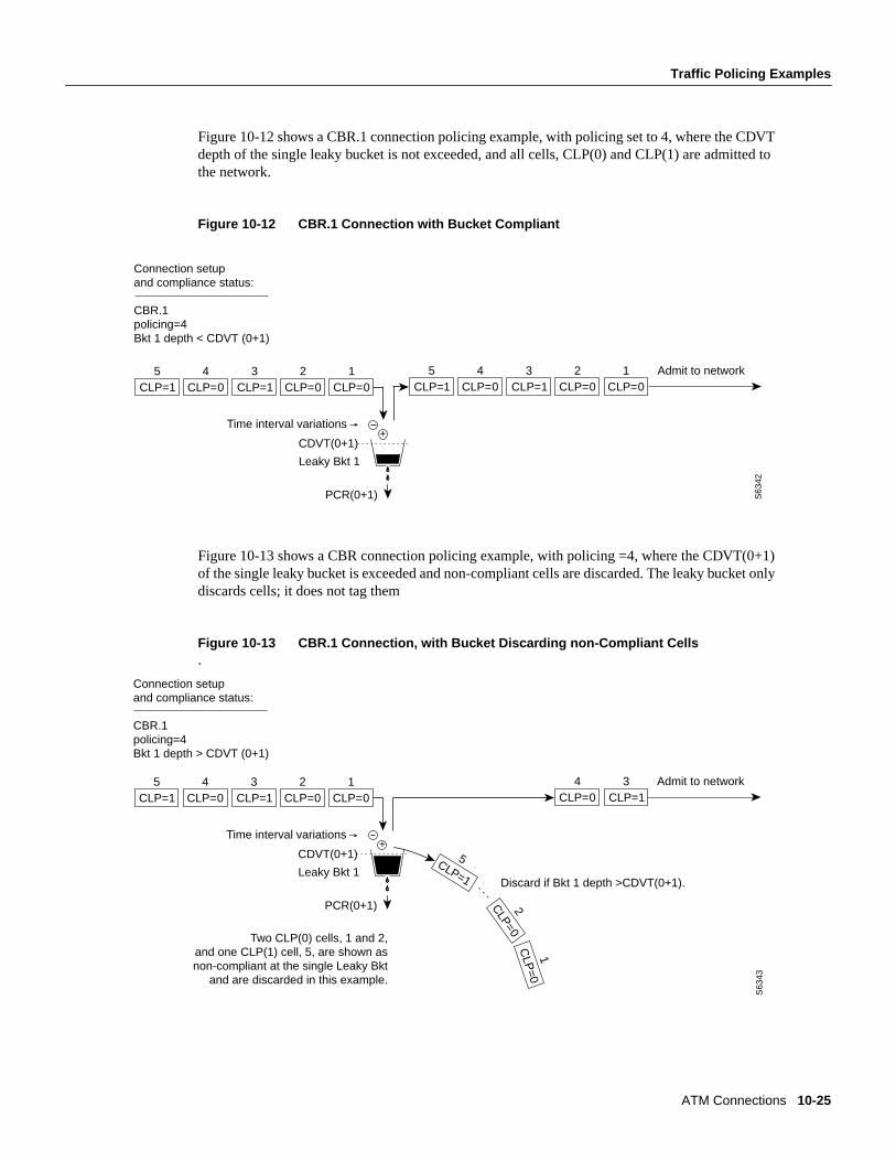
Figure 10-12 shows a CBR.1 connection policing example, with policing set to 4, where the CDVTdepth of the single leaky bucket is not exceeded, and all cells, CLP(0) and CLP(1) are admitted tothe network.
Figure 10-12 CBR.1 Connection with Bucket Compliant
Figure 10-13 shows a CBR connection policing example, with policing =4, where the CDVT(0+1)of the single leaky bucket is exceeded and non-compliant cells are discarded. The leaky bucket onlydiscards cells; it does not tag them
Figure 10-13 CBR.1 Connection, with Bucket Discarding non-Compliant Cells.
S63
42
Connection setup and compliance status: CBR.1policing=4Bkt 1 depth < CDVT (0+1)
CLP=15
CLP=04
CLP=13
CLP=02
CLP=01
+
PCR(0+1)
CDVT(0+1)
Time interval variations
Leaky Bkt 1
Admit to networkCLP=1
5CLP=0
4CLP=1
3CLP=0
2CLP=0
1
CLP=1
5
CLP=0
2C
LP=0
1
S63
43
Two CLP(0) cells, 1 and 2, and one CLP(1) cell, 5, are shown as
non-compliant at the single Leaky Bkt and are discarded in this example.
Discard if Bkt 1 depth >CDVT(0+1).
CLP=15
CLP=04
CLP=13
CLP=02
CLP=01
+
PCR(0+1)
CDVT(0+1)
Time interval variations
Leaky Bkt 1
Admit to networkCLP=0
4CLP=1
3
Connection setup and compliance status: CBR.1policing=4Bkt 1 depth > CDVT (0+1)
10-26 Cisco StrataCom System Overview
Traffic Policing Examples
VBR Dual-Leaky Bucket Policing ExamplesThe contract for a variable bit rate connection is set up based on an agreed upon sustained cell rate(SCR) with allowance for occasional data bursts at a Peak Cell Rate (PCR) as specified by maximumburst size MBS.
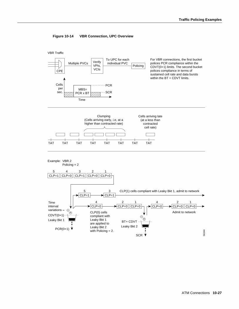
When a connection is added, a VPI.VCI address is assigned, and UPC parameters are configured forthe connection. For each cell in an ATM stream, the VPI.VCI addresses are verified and each cell ischecked for compliance with the UPC parameters as shown in Figure 10-14.
The VBR cells are not enqueued, but are processed by the policing function and then sent to thenetwork unless discarded.
For VBR, traffic policing, depending on selected policing option, is based on:
• Leaky bucket 1, PCR and CDVT
• Leaky bucket 2, SCR, CDVT, and MBS
The policing options, selected by entering 1-5 in response to the policing choice prompt, are asfollows for VBR connections:
VBR.1
VBR with policingset to 1.
CLP(0+1) cells compliant with leaky bucket 1 are passed to leaky bucket 2;non-compliant cells are discarded. CLP(0+1) cells compliant with leaky bucket 2are admitted to the network; non-compliant cells are discarded.
VBR.2
VBR with policingset to 2.
CLP(1) cells compliant with leaky bucket 1 are admitted to the network; non-compliantCLP(0+1) cells are dropped. CLP(0) cells compliant with leaky bucket 1 are applied toleaky bucket 2; non-compliant cells are dropped. CLP(0) cells compliant with leakybucket 2 are admitted to the network; non-compliant cells are dropped.
VBR.3
VBR with policingset to 3.
VBR.3. CLP(1) cells compliant with leaky bucket 1 are admitted to the network;non-compliant CLP(0+1) cells are dropped. CLP(0) cells compliant with leaky bucket 1are applied to leaky bucket 2; non-compliant cells are dropped. CLP(0) cells compliantwith leaky bucket 2 are admitted to the network; non-compliant cells are tagged andadmitted to the network.
VBR with policingset to 4.
CLP(0+1) cells compliant with leaky bucket 1 are admitted to the network;non-compliant cells are dropped. Leaky bucket 2 is not active.
VBR with policingset to 5.
Policing is off, so there is no policing of cells on ingress.
ATM Connections 10-27
Traffic Policing Examples
Figure 10-14 VBR Connection, UPC Overview
S63
44
Admit to network
+
SCR
BT + CDVT
Leaky Bkt 2
For VBR connections, the first bucket polices PCR compliance within the CDVT(0+1) limits. The second bucket polices compliance in terms of sustained cell rate and data bursts within the BT + CDVT limits.
VBR Traffic
CPE
Multiple PVCsTo UPC for eachindividual PVC
PCR
Clumping (Cells arriving early, i.e, at a higher than contracted rate)
Cells arriving late(at a less than
contracted cell rate)
TAT TAT TAT TAT TAT TAT TAT TAT
VerifyVPIs,VCIs
Policing
CLP=15
CLP=04
CLP=13
CLP=02
CLP=01
+
PCR(0+1)
CDVT(0+1)
Time intervalvariations
Leaky Bkt 1
CLP=15
CLP=13
CLP=04
CLP=02
CLP=01
Example: VBR.2 Policing = 2
CLP=04
CLP=02
CLP=01
CLP(1) cells compliant with Leaky Bkt 1, admit to network
CLP(0) cells compliant with Leaky Bkt 1 are applied to Leaky Bkt 2 with Policing = 2.
Time
Cellsper
sec. SCR MBS=
PCR x BT
10-28 Cisco StrataCom System Overview
Traffic Policing Examples
Leaky Bucket 1Leaky bucket 1 polices for the PCR compliance of all cells seeking admission to the network, boththose with CLP = 0 and those with CLP =1. For example, cells seeking admission to the networkwith CLP set equal to 1 may have either encountered congestion along the user’s network or mayhave lower importance to the user and have been designated as eligible for discard in the casecongestion is encountered. If the bucket depth in the first bucket exceeds CDVT (0+1), it discardsall cells seeking admission. It does not tag cells.
With policing set to 1 (VBR.1), all cells (CLP=0 and CLP=1) that are compliant with leaky bucket1, are sent to leaky bucket 2. With policing set to 2 (VBR.2) or to 3 (VBR.3), all CLP=1 cellscompliant with leaky bucket 1 are admitted directly to the network, and all CLP=0 cells compliantwith leaky bucket 1 are sent to leaky bucket 2.
Leaky Bucket 2For VBR connections, the purpose of leaky bucket 2 is to police the cells passed from leaky bucket1 for conformance with maximum burst size MBS as specified by BT and for compliance with theSCR sustained cell rate. The types of cells passed to leaky bucket 2 depend on how policing is set:
• For policing set to 5, cells bypass both buckets.
• For policing set to 4, leaky bucket 2 sees no traffic.
• For policing set to 2 or 3, the CLP(0) cells are admitted to the network if compliant with BT +CDVT of leaky bucket 2. If not compliant, cells may either be tagged (policing set to 3) ordiscarded (policing set to 2).
• For policing set to 1, the CLP(0) and CLP(1) cells are admitted to the network if compliant withBT + CDVT of leaky bucket 2. If not compliant, the cells are discarded. There is no taggingoption.
ATM Connections 10-29
Traffic Policing Examples
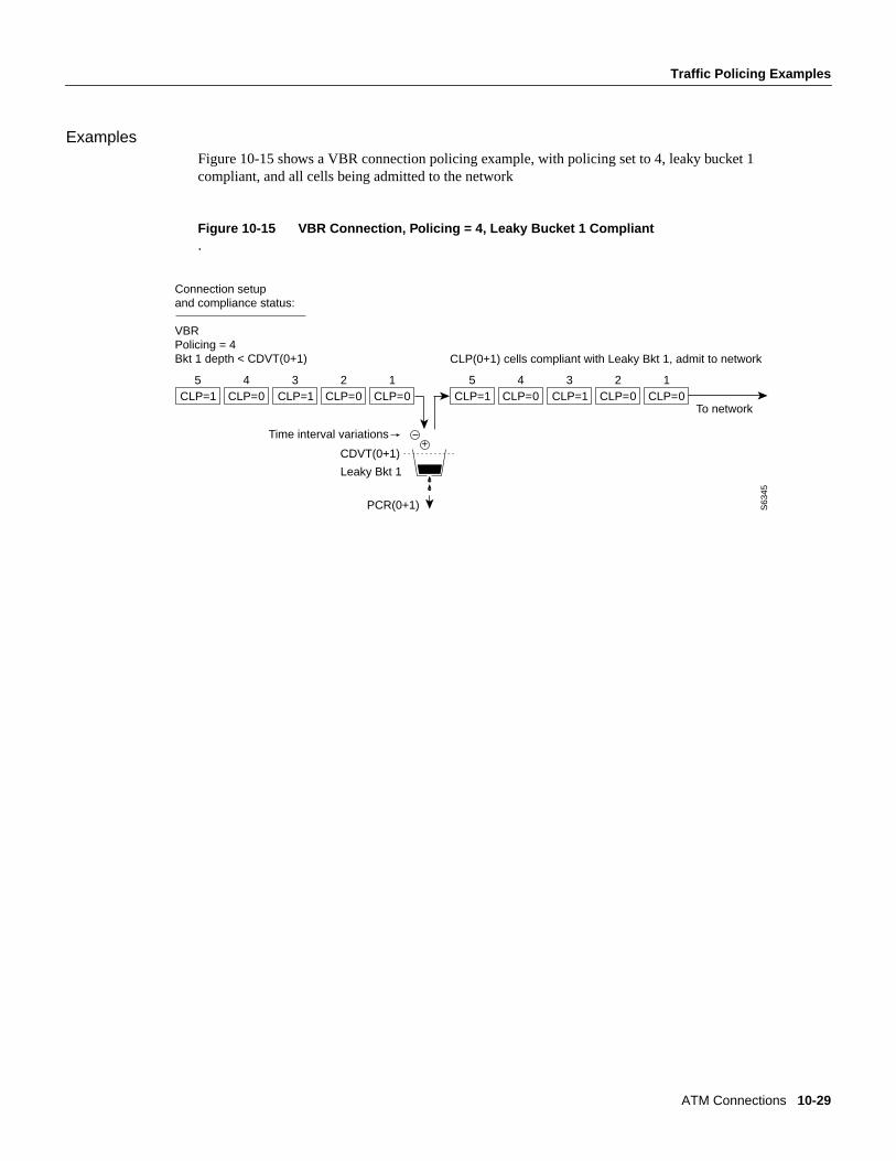
ExamplesFigure 10-15 shows a VBR connection policing example, with policing set to 4, leaky bucket 1compliant, and all cells being admitted to the network
Figure 10-15 VBR Connection, Policing = 4, Leaky Bucket 1 Compliant.
S63
45
CLP=15
CLP=04
CLP=13
CLP=02
CLP=01
+
PCR(0+1)
CDVT(0+1)
Time interval variations
Leaky Bkt 1
Connection setupand compliance status: VBRPolicing = 4Bkt 1 depth < CDVT(0+1)
CLP=15
CLP=04
CLP=13
CLP=02
CLP=01
To network
CLP(0+1) cells compliant with Leaky Bkt 1, admit to network
10-30 Cisco StrataCom System Overview
Traffic Policing Examples
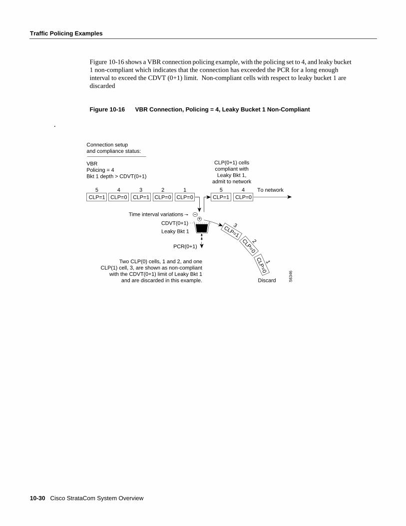
Figure 10-16 shows a VBR connection policing example, with the policing set to 4, and leaky bucket1 non-compliant which indicates that the connection has exceeded the PCR for a long enoughinterval to exceed the CDVT (0+1) limit. Non-compliant cells with respect to leaky bucket 1 arediscarded
Figure 10-16 VBR Connection, Policing = 4, Leaky Bucket 1 Non-Compliant
.
Connection setupand compliance status: VBRPolicing = 4Bkt 1 depth > CDVT(0+1)
5
CLP(0+1) cells compliant with Leaky Bkt 1,
admit to network
CLP=1
3
CLP=02
CLP
=01
S63
46
To networkCLP=1 CLP=0
4CLP=1
3CLP=0
2CLP=0
1CLP=1
5CLP=0
4
+
PCR(0+1)
CDVT(0+1)
Time interval variations
Leaky Bkt 1
Two CLP(0) cells, 1 and 2, and one CLP(1) cell, 3, are shown as non-compliant
with the CDVT(0+1) limit of Leaky Bkt 1 and are discarded in this example. Discard
ATM Connections 10-31
Traffic Policing Examples
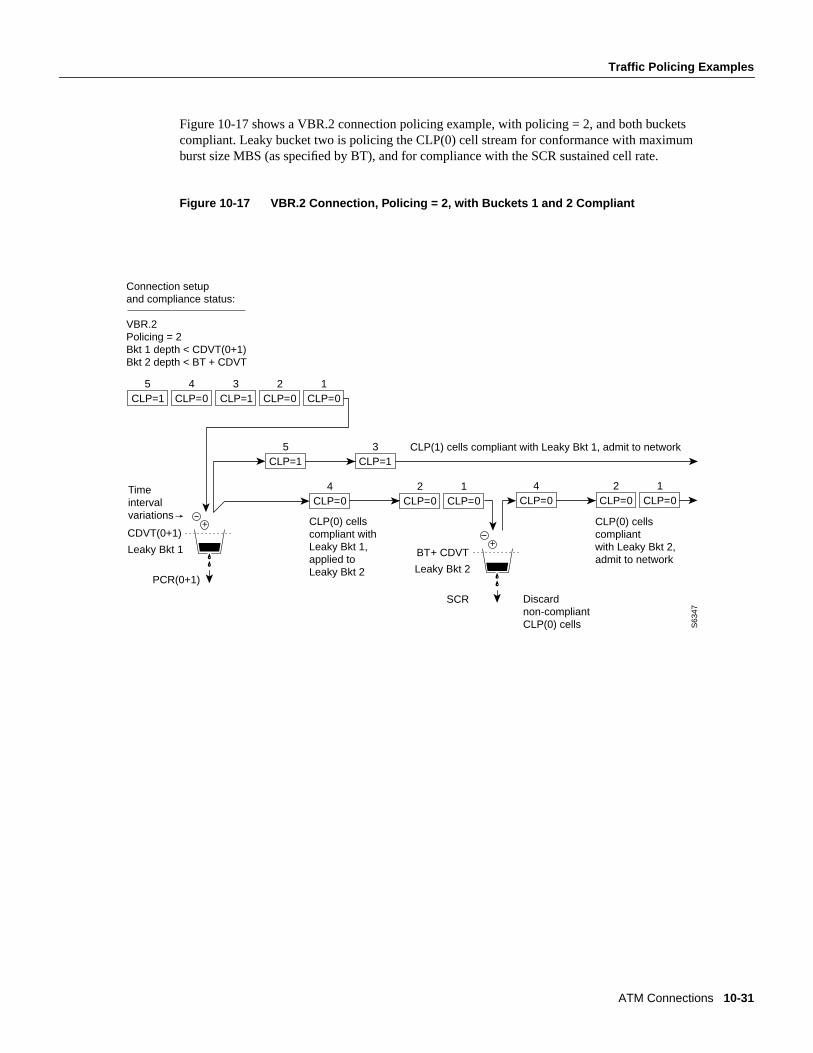
Figure 10-17 shows a VBR.2 connection policing example, with policing = 2, and both bucketscompliant. Leaky bucket two is policing the CLP(0) cell stream for conformance with maximumburst size MBS (as specified by BT), and for compliance with the SCR sustained cell rate.
Figure 10-17 VBR.2 Connection, Policing = 2, with Buckets 1 and 2 Compliant
CLP(0) cells compliantwith Leaky Bkt 2,admit to network
+
SCR
BT + CDVT
Leaky Bkt 2
CLP=15
CLP=04
CLP=13
CLP=02
CLP=01
+
PCR(0+1)
CDVT(0+1)
Time intervalvariations
Leaky Bkt 1
CLP=15
CLP=13
CLP=04
CLP=02
CLP=01
CLP=04
CLP=02
CLP=01
CLP(1) cells compliant with Leaky Bkt 1, admit to network
CLP(0) cells compliant withLeaky Bkt 1, applied to Leaky Bkt 2
Connection setupand compliance status: VBR.2Policing = 2Bkt 1 depth < CDVT(0+1)Bkt 2 depth < BT + CDVT
S63
47
Discardnon-compliantCLP(0) cells
10-32 Cisco StrataCom System Overview
Traffic Policing Examples
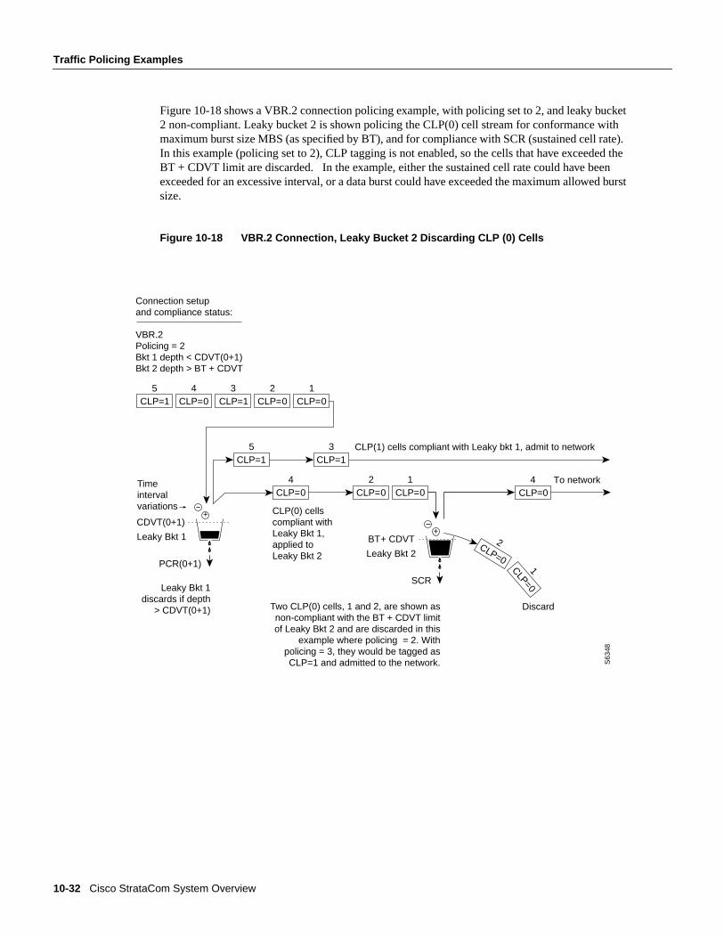
Figure 10-18 shows a VBR.2 connection policing example, with policing set to 2, and leaky bucket2 non-compliant. Leaky bucket 2 is shown policing the CLP(0) cell stream for conformance withmaximum burst size MBS (as specified by BT), and for compliance with SCR (sustained cell rate).In this example (policing set to 2), CLP tagging is not enabled, so the cells that have exceeded theBT + CDVT limit are discarded. In the example, either the sustained cell rate could have beenexceeded for an excessive interval, or a data burst could have exceeded the maximum allowed burstsize.
Figure 10-18 VBR.2 Connection, Leaky Bucket 2 Discarding CLP (0) Cells
+
SCR
BT + CDVT
Leaky Bkt 2
CLP=15
CLP=04
CLP=13
CLP=02
CLP=01
+
PCR(0+1)
CDVT(0+1)
Time intervalvariations
Leaky Bkt 1
CLP=15
CLP=13
CLP=04
CLP=02
CLP=01
CLP(1) cells compliant with Leaky bkt 1, admit to network
CLP(0) cells compliant withLeaky Bkt 1, applied to Leaky Bkt 2
Connection setupand compliance status: VBR.2Policing = 2Bkt 1 depth < CDVT(0+1)Bkt 2 depth > BT + CDVT
S63
48
CLP=0
2
CLP=01
To networkCLP=0
4
Two CLP(0) cells, 1 and 2, are shown as non-compliant with the BT + CDVT limit of Leaky Bkt 2 and are discarded in this
example where policing = 2. With policing = 3, they would be tagged as CLP=1 and admitted to the network.
Discard
Leaky Bkt 1 discards if depth
> CDVT(0+1)
ATM Connections 10-33
Traffic Policing Examples
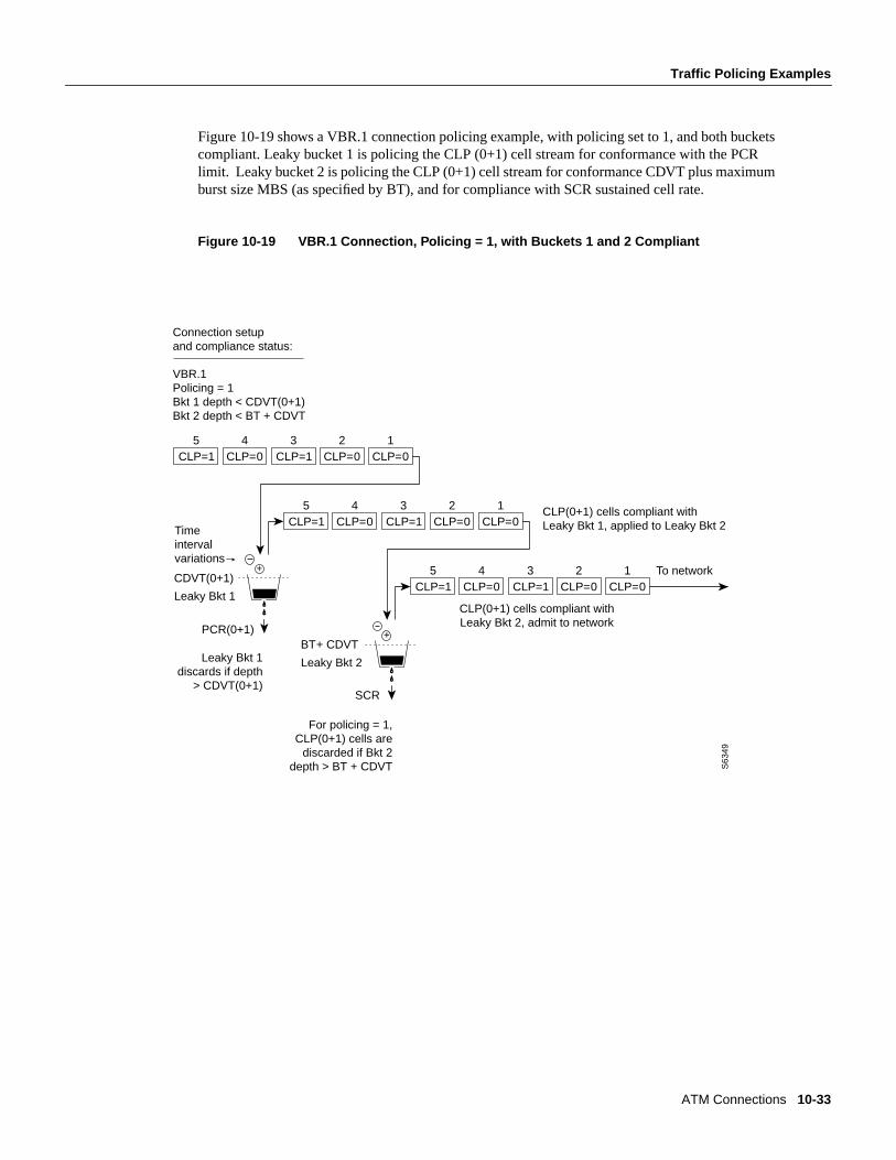
Figure 10-19 shows a VBR.1 connection policing example, with policing set to 1, and both bucketscompliant. Leaky bucket 1 is policing the CLP (0+1) cell stream for conformance with the PCRlimit. Leaky bucket 2 is policing the CLP (0+1) cell stream for conformance CDVT plus maximumburst size MBS (as specified by BT), and for compliance with SCR sustained cell rate.
Figure 10-19 VBR.1 Connection, Policing = 1, with Buckets 1 and 2 Compliant
CLP(0+1) cells compliant with Leaky Bkt 2, admit to network
+
SCR
BT + CDVT
Leaky Bkt 2
CLP=15
CLP=04
CLP=13
CLP=02
CLP=01
+
PCR(0+1)
CDVT(0+1)
Time intervalvariations
Leaky Bkt 1
CLP(0+1) cells compliant with Leaky Bkt 1, applied to Leaky Bkt 2
Connection setupand compliance status: VBR.1Policing = 1Bkt 1 depth < CDVT(0+1)Bkt 2 depth < BT + CDVT
S63
49
Leaky Bkt 1discards if depth
> CDVT(0+1)
CLP=15
CLP=04
CLP=13
CLP=02
CLP=01
CLP=15
CLP=04
CLP=13
CLP=02
CLP=01 To network
For policing = 1, CLP(0+1) cells are
discarded if Bkt 2 depth > BT + CDVT
10-34 Cisco StrataCom System Overview
Traffic Policing Examples
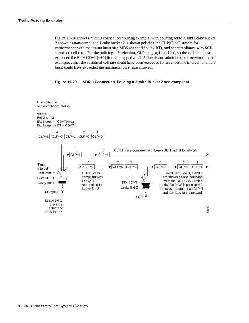
Figure 10-20 shows a VBR.3 connection policing example, with policing set to 3, and Leaky bucket2 shown as non-compliant. Leaky bucket 2 is shown policing the CLP(0) cell stream forconformance with maximum burst size MBS (as specified by BT), and for compliance with SCRsustained cell rate. For the policing = 3 selection, CLP tagging is enabled, so the cells that haveexceeded the BT + CDVT(0+1) limit are tagged as CLP=1 cells and admitted to the network. In thisexample, either the sustained cell rate could have been exceeded for an excessive interval, or a databurst could have exceeded the maximum burst size allowed.
Figure 10-20 VBR.3 Connection, Policing = 3, with Bucket 2 non-compliant
CLP=15
CLP=04
CLP=13
CLP=02
CLP=01
+
PCR(0+1)
CDVT(0+1)
Time intervalvariations
Leaky Bkt 1
Connection setupand compliance status: VBR.3Policing = 3Bkt 1 depth < CDVT(0+1)Bkt 2 depth > BT + CDVT
S63
50
Leaky Bkt 1 discards
if depth > CDVT(0+1)
+
SCR
BT + CDVT
Leaky Bkt 2
CLP=15
CLP=13
CLP=04
CLP=02
CLP=01
CLP=04
CLP=12
CLP=11
CLP(1) cells compliant with Leaky Bkt 1, admit to network
CLP(0) cells compliant withLeaky Bkt 1 are applied to Leaky Bkt 2
Two CLP(0) cells, 1 and 2,are shown as non-compliant with the BT + CDVT limit of
Leaky Bkt 2. With policing = 3, the cells are tagged as CLP=1
and admitted to the network.
ATM Connections 10-35
Traffic Policing Examples
ABR Connection PolicingAvailable Bit Rate (ABR) connections are policed the same as the VBR connections, but in additionuse either the ABR Standard with VSVD congestion flow control method or the ForeSight option totake advantage of unused bandwidth when it is available.
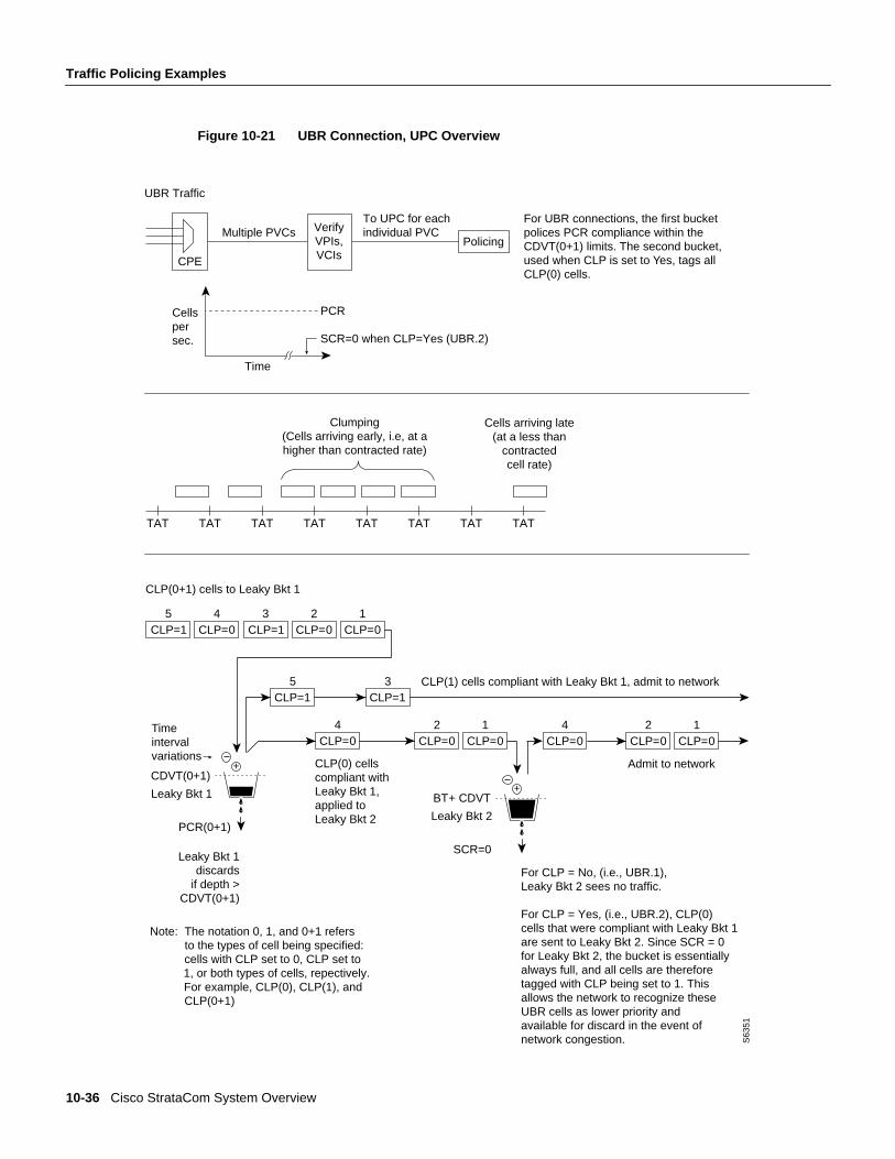
UBR Connection PolicingThe contract for a unspecified bit rate connection is similar to the ABR connection service for burstydata. However, UBR traffic is delivered only when there is spare bandwidth in the network.
When a connection is added, a VPI.VCI address is assigned, and UPC parameters are configured forthe connection. For each cell in an ATM stream, the VPI.VCI addresses are verified and each cell ischecked for compliance with the UPC parameters as shown in Figure 10-21.
Leaky Bucket 1Leaky bucket 1 polices the UBR connection for PCR compliance. When CLP=No (UBR.1), all cellsthat are compliant with leaky bucket 1 are applied to the network. However, these cells are treatedwith low priority in the network with % utilization default of 1%.
Leaky Bucket 2When CLP=Yes (UBR.2), CLP(0) cells that are compliant with leaky bucket 1 are sent to leakybucket 2. Since SCR=0 for leaky bucket 2, the bucket is essentially always full, and all the CLP(0)cells sent to leaky bucket 2 are therefore tagged with CLP being set to 1. This allows the network torecognize these UBR cells as lower priority cells and available for discard in the event of networkcongestion.
10-36 Cisco StrataCom System Overview
Traffic Policing Examples
Figure 10-21 UBR Connection, UPC Overview
CLP=15
CLP=04
CLP=13
CLP=02
CLP=01
+
PCR(0+1)
CDVT(0+1)
Time intervalvariations
Leaky Bkt 1
CLP(0+1) cells to Leaky Bkt 1
S63
51
Leaky Bkt 1 discards
if depth > CDVT(0+1)
Admit to network
+
SCR=0
BT + CDVT
Leaky Bkt 2
CLP=15
CLP=13
CLP=04
CLP=02
CLP=01
CLP=04
CLP=02
CLP=01
CLP(1) cells compliant with Leaky Bkt 1, admit to network
CLP(0) cells compliant withLeaky Bkt 1, applied to Leaky Bkt 2
For UBR connections, the first bucketpolices PCR compliance within theCDVT(0+1) limits. The second bucket,used when CLP is set to Yes, tags allCLP(0) cells.
UBR Traffic
CPE
Multiple PVCsTo UPC for eachindividual PVC
Time
Cellspersec.
PCR
SCR=0 when CLP=Yes (UBR.2)
Clumping (Cells arriving early, i.e, at a higher than contracted rate)
Cells arriving late(at a less than
contracted cell rate)
TAT TAT TAT TAT TAT TAT TAT TAT
VerifyVPIs,VCIs
Policing
Note: The notation 0, 1, and 0+1 refers to the types of cell being specified: cells with CLP set to 0, CLP set to 1, or both types of cells, repectively. For example, CLP(0), CLP(1), and CLP(0+1)
For CLP = No, (i.e., UBR.1), Leaky Bkt 2 sees no traffic.
For CLP = Yes, (i.e., UBR.2), CLP(0) cells that were compliant with Leaky Bkt 1 are sent to Leaky Bkt 2. Since SCR = 0for Leaky Bkt 2, the bucket is essentially always full, and all cells are therefore tagged with CLP being set to 1. This allows the network to recognize these UBR cells as lower priority and available for discard in the event of network congestion.
ATM Connections 10-37
LMI and ILMI Parameters
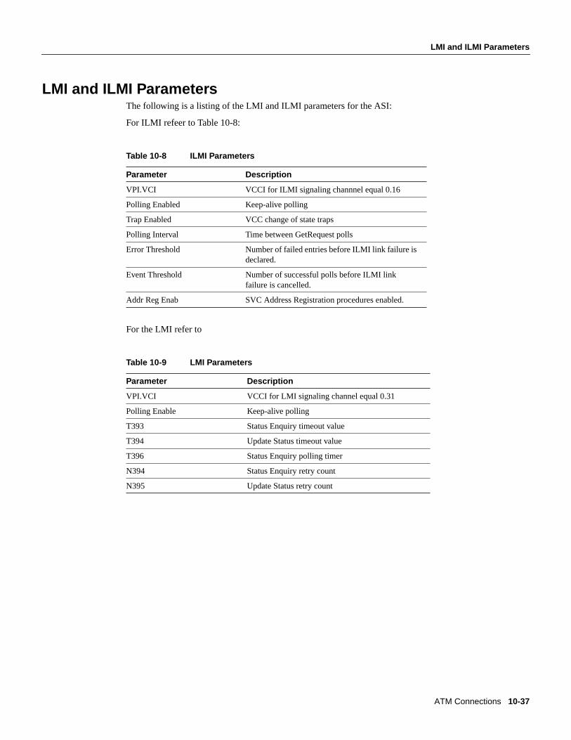
LMI and ILMI ParametersThe following is a listing of the LMI and ILMI parameters for the ASI:
For ILMI refeer to Table 10-8:
Table 10-8 ILMI Parameters
For the LMI refer to
Table 10-9 LMI Parameters
Parameter Description
VPI.VCI VCCI for ILMI signaling channnel equal 0.16
Polling Enabled Keep-alive polling
Trap Enabled VCC change of state traps
Polling Interval Time between GetRequest polls
Error Threshold Number of failed entries before ILMI link failure isdeclared.
Event Threshold Number of successful polls before ILMI linkfailure is cancelled.
Addr Reg Enab SVC Address Registration procedures enabled.
Parameter Description
VPI.VCI VCCI for LMI signaling channel equal 0.31
Polling Enable Keep-alive polling
T393 Status Enquiry timeout value
T394 Update Status timeout value
T396 Status Enquiry polling timer
N394 Status Enquiry retry count
N395 Update Status retry count
10-38 Cisco StrataCom System Overview
LMI and ILMI Parameters