ATIS-0x0000x · Web viewATIS and the SIP Forum further expressly advise that any use of or reliance...
50
ATIS-1000063 ATIS Standard on IP NNI Profile Alliance for Telecommunications Industry Solutions Approved Month DD, YYYY Abstract Abstract text here.
Transcript of ATIS-0x0000x · Web viewATIS and the SIP Forum further expressly advise that any use of or reliance...

ATIS-1000063
ATIS Standard on
IP NNI Profile
Alliance for Telecommunications Industry Solutions
Approved Month DD, YYYY
AbstractAbstract text here.
ATIS-1000063
Foreword
The Alliance for Telecommunications Industry Solutions (ATIS) serves the public through improved understanding between carriers, customers, and manufacturers. The [COMMITTEE NAME] Committee [INSERT MISSION]. [INSERT SCOPE].
The SIP Forum’s mission is to advance the adoption of products and services based on the Session Initiation Protocol and to maintain and serve a global community of commercial SIP based service and technology providers. The primary goals of the SIP Forum are to foster interoperability and adherence to standardization efforts, and provide educational resources and a platform for productive communication among industry participants.
Notice of Use
Neither ATIS nor the SIP Forum makes any representation or warranty, express or implied, with respect to the sufficiency, accuracy or utility of the information or opinion contained or reflected in the material utilized. ATIS and the SIP Forum further expressly advise that any use of or reliance upon the material in question is at your risk and neither ATIS nor the SIP Forum shall be liable for any damage or injury, of whatever nature, incurred by any person arising out of any utilization of the material. It is possible that this material will at some future date be included in a copyrighted work by ATIS or the SIP Forum.
Notice of ApplicabilityThis document was developed by the ATIS/SIP Forum IP-NNI Task Force and is subject to change. The implementation of recommendations, methods and descriptions in this document are not mandatory and participation in the task force does not obligate any ATIS member company to use them.
This document represents the consensus view of the task force however the consensus views expressed herein should not be interpreted as an endorsement by any ATIS member company to create a new technical or regulatory requirement for commercial interconnection arrangements.
Suggestions for improvement of this document are welcome. They should be sent to the Alliance for Telecommunications Industry Solutions, [COMMITTEE NAME], 1200 G Street NW, Suite 500, Washington, DC 20005.
At the time of consensus on this document, [COMMITTEE NAME], which was responsible for its development, had the following leadership:
[LEADERSHIP LIST]
The [SUBCOMMITTEE NAME] Subcommittee was responsible for the development of this document.
[Type here]

ATIS-1000063
Table of Contents
[INSERT]
Table of Figures
[INSERT]
Table of Tables
[INSERT]
[Type here]
ATIS STANDARD ATIS-1000063
ATIS Standard on –
IP Interconnection
1 Scope, Purpose, & Application1.1 ScopeThis document was developed under a joint ATIS and SIP Forum collaboration. The document defines an IP NNI profile with an emphasis on VoIP. Other Multimedia services will be addressed in subsequent releases.
The scope of this profile document is to:
1. Define a reference architecture that sets forth the common functional entities for Carrier to Carrier Interconnection. This reference architecture will be from the perspective of the interconnection points between carriers and will not deal with implementation details inside the networks on either side of the IP-NNI.
2. Define the normative standards (including IETF RFCs, 3GPP, and other existing standards) associated with these protocols that are supported by each element of the reference architecture. Where required, the options that MUST or SHOULD be supported within a given standard will also be defined for this profile.
3. Define for this profile the customary methods for negotiating protocols, protocol extensions, and exchanging capability information between carriers. The methods of formulating SIP protocol messages are where multiple options exist in standards.
4. Define for this profile the presentations of Fully Qualified Domain Names in “From:” and “To:” fields, including P-Asserted Identity (PAI).
5. Define support for underlying transport [e.g. UDP, TCP, SCTP].6. Define an audio codec selection strategy that minimizes the need for transcoding and a transcoding
strategy that balances the workload between originating and terminating carrier.7. Define strategies for DTMF and Fax support.8. Specify call loop detection and avoidance methods.9. Include recommendations for network overload and congestion notification and processing mechanisms.
1.2 PurposeIP Interconnection among service providers is significantly increasing as the transition of the PSTN from SS7/TDM to SIP/IP networks progresses. Current deployments of SIP/IP in the core carrier networks have exposed operational and implementation differences on how IP for SIP traffic works ‘on the wire’. These differences complicate interconnection, and in some cases require ‘protocol normalization’ to achieve full interoperability. The call control protocol SIP [RFC 3261] is defined in the IETF and is further refined by 3GPP or ATIS that reflect regional and/or national differences in implementation. There are hundreds of IETF SIP and 3GPP specifications that are open to interpretation, creating ambiguity in the detailed options that are implemented. This often requires Session Border Controllers or IBCF proxies reconcile the signaling between service providers and resolving those ambiguities. Time and effort is also required to document the differences and configure the SBC or IBCF proxy to implement the necessary changes to the on the wire protocol.
The purpose of this effort is to identify a baseline set of features that should be common to all IP-NNI implementations for voice service.
This document defines the standards and options that are supported for this NNI Profile. They will provide carriers with a precise description of the IP-NNI in the areas where the standards leave multiple options, or where the existing specifications are ambiguous.
This document uses key words like MUST, MAY and SHALL in accordance with RFC-2119..
1
ATIS-1000063
1.3 ApplicationThis document defines an NNI Profile that may be used for USA and Canadian deployments, but may be applicable for deployments outside USA and Canada.Impact on Services - The NNI Profile described by this document is not intended to “certify” equipment and does not establish a new “compliance” requirement for existing or future products and services offered by any ATIS member company.
Impact on Interconnection Arrangements - The NNI Profile described in this document does not account for every interconnection scenario and although Providers may voluntarily employ it to facilitate interconnection planning, it is not a replacement for the technical discussions required during the development of commercial interconnection arrangements.
Impact on Regulations - Commercial interconnection arrangements allow Providers to address differences in their network and customer needs, and establishing this NNI Profile as an ATIS Standard or Technical Report is not an endorsement by any ATIS member company to alter any existing regulatory obligation, or create a new regulatory obligation.
2 Normative ReferencesThe following standards contain provisions which, through reference in this text, constitute provisions of this Standard. At the time of publication, the editions indicated were valid. All standards are subject to revision, and parties to agreements based on this Standard are encouraged to investigate the possibility of applying the most recent editions of the standards indicated below.
[RFC 2474] IETF RFC - Definition of the Differentiated Services Field (DS Field) in the IPv4 and IPv6 Headers
[RFC 2597] IETF RFC - Assured Forwarding PHB Group
[RFC 3247] IETF RFC - Supplemental Information for the New Definition of the EF PHB (Expedited Forwarding Per-Hop Behavior)
[RFC 3261] IETF RFC - SIP: Session Initiation Protocol
[RFC 3262] IETF RFC - Reliability of Provisional Responses in Session Initiation Protocol (SIP)
[RFC 3264] IETF RFC - An Offer/Answer Model with Session Description Protocol (SDP)
[RFC 3312] IETF RFC 3312 – Integration of Resource Management and Session Initiation Protocol (SIP)
[RFC 3323] IETF RFC - A Privacy Mechanism for the Session Initiation Protocol (SIP)
[RFC 3325] IETF RFC - Private Extensions to the Session Initiation Protocol (SIP) for Asserted Identity within Trusted Networks
[RFC 3725] IETF RFC - Best Current Practices for Third Party Call Control (3pcc) in the Session Initiation Protocol (SIP)
[RFC 3841] IETF RFC – Caller Preferences for the Session Initiation Protocol (SIP)
[RFC 3966] IETF RFC - The tel URI for Telephone Numbers
[RFC 4028] IETF RFC - Session Timers in the Session Initiation Protocol (SIP)
[RFC 4566] IETF RFC - SDP: Session Description Protocol
[RFC 4694] IETF RFC - Number Portability Parameters for the "tel" URI
[RFC 4733] IETF RFC 4733 – RTP Payload for DTMF Digits, Telephony Tones, and Telephony Signals
[RFC 5009] IETF RFC - Private Header (P-Header) Extension to the Session Initiation Protocol (SIP) for Authorization of Early Media
[Type here]

ATIS-1000063[RFC 7339] IETF RFC - Session Initiation Protocol (SIP) Overload Control
[T.38] ITU-T Recommendation T.38 (09/2010) – Procedures for real-time Group 3 facsimile communication over IP networks
[V.150.1] ITU-T Recommendation V.150.1 (01/2003) – Modem-over-IP networks: Procedures for the end-to-end connection of V-series DCEs
[V.152] ITU-T Recommendation V.152 (09/2010) – Procedures for supporting voice-band data over IP networks
[TS 24.229] 3GPP specification - IP multimedia call control protocol based on Session Initiation Protocol (SIP) and Session Description Protocol (SDP); Stage 3
[TS 29.165] 3GPP specification – Inter-IMS Network-to-Network Interface (NNI)
3 Definitions, Acronyms, & AbbreviationsFor a list of common communications terms and definitions, please visit the ATIS Telecom Glossary, which is located at < http://www.atis.org/glossary >.
3.1 DefinitionsAAA: xxxx.
Bbbb: xxxx.
3.2 Acronyms & Abbreviations 3GPP 3rd Generation Partnership Project
ALG Application Level Gateway
AMR Adaptive Multi-Rate
AS Application Server
ATCF Access Transfer Control Function
B2BUA Back to Back User Agent
BGCF Border Gateway Control Function
BGP Border Gateway Protocol
BSR Base Station Router
CN Core Network
CSCF Call Session Control Function
CPE Consumer Premise Equipment
DBE Domain Border Element
DCB Data Configuration and Bootstrap
DSCP Differentiated services code point
DTMF Dual-Tone Multi-frequency
FAX Facsimile
FE Functional Entity
GSMA Groupe Speciale Mobile Association
IBCF Interconnection Border Control Function
[Type here]
ATIS-1000063I-BGF Interconnection Border Gateway Function
I-CSCF Interrogating-Call Session Control Function
ICSS IMS Centralized Services
IETF Internet Engineering Task Force
IMS IP Multimedia Subsystem
IMS-ALG Multimedia Subsystem Application Level Gateway
IP Internet Protocol
IPSec IP Security
IPv4 Internet Protocol Version 4
IPv6 Internet Protocol Version 6
LATA Local Access and Transport Area
LNP Local Number Portability
MGCF Media Gateway Control Function
MGF Media Gateway Function
MIME Multipurpose Internet Mail Extensions
MMS Multimedia Message Switching
MPLS Multiprotocol Label Switching
MSC Mobile Switching Center
NANP North American Numbering Plan
NAT Network Address Translation
NAT-PT Network Address Translation—Protocol Translation
NBE Network Border Element
NE Network Element
NNI Network to Network Interface
NS/EP National Security/Emergency Prepardness
OAMP Operations, Administration, Maintenance and Provisioning
ONU Optical Unit
P-CSCF Proxy Call Session Control Function
PBX Public Branch Exchange
PSTN Public Switched Telephone Network
QoS Quality of Service
RTP Real-Time Protocol
SBC Session Border Controller
S-CSCF Serving-Call Session Control Function
SCTP Stream Control Transmission Protocol
SDP Session Description Protocol
SGF Signalling Gateway Function
SID Silence Indicator
SIP Session Initiation Protocol
SIP URI SIP protocol Uniform Resource Identifier
[Type here]

ATIS-1000063SIP-I SIP with encapsulated ISUP
SIP-T SIP for Telephones
SLA Service Level Agreement
SMS Short Message Service
SRVCC Single Radio Voice Call Continuity
TCP Transmission Control Protocol
TDM Time-Division Multiplex
TE Terminal Equipment
tel-URI Telephone Uniform Resource Identifier
TRF Transit and Roaming Function
TrFO Transcoder Free Operation
TrGw Transition Gateway
TLS Transport Layer Security
UA User Agent
UDP User Datagram Protocol
URI Uniform Resource Identifier
VBD Voice Band Data
VoIP Voice over IP
VPN Virtual Private Network
WB Wide-Band
WS Web Server
4 Reference Model for Interconnection4.1 Current US Telephony PSTN Interconnect ModelThe figure below depicts the current US Telephony PSTN architecture and interconnect model. This architecture is characterized by:
One or more end office local switching systems interconnected within a limited geographic area (e.g., LATA or MSA)..
One or more inter-exchange carrier networks providing interconnect services between these networks.
[Type here]

ATIS-1000063
Figure 4. 1 - Current US Telephony PSTN Interconnect Model
The end office switches may be supporting voice service via wireline, wireless, and/or cable –based access networks. They will interconnect through tandem switches or through direct connections.
Interconnectivity between LATAs is provided by transit carrier networks. These networks provide interconnect services between access carrier networks. An inter-exchange carrier’s network may connect to an access tandem and/or directly to the end office switches.
4.2 VoIP Interconnection Basic Configuration VoIP in this context will coexist with SMS, MMS, Multimedia features, video calling, and other Real Time Communications features that may come available.
VoIP has been introduced into the traditional PSTN network architecture in a variety of places, forming islands of VoIP that must interconnect. For example VoIP could be used in:
Enterprise PBX networks.
Local networks.
[Type here]
Scope of IPNNI profile
TerminatingCarrier
TransitCarrier
OriginatingCarrier

ATIS-1000063 Tandem and inter-exchange networks.
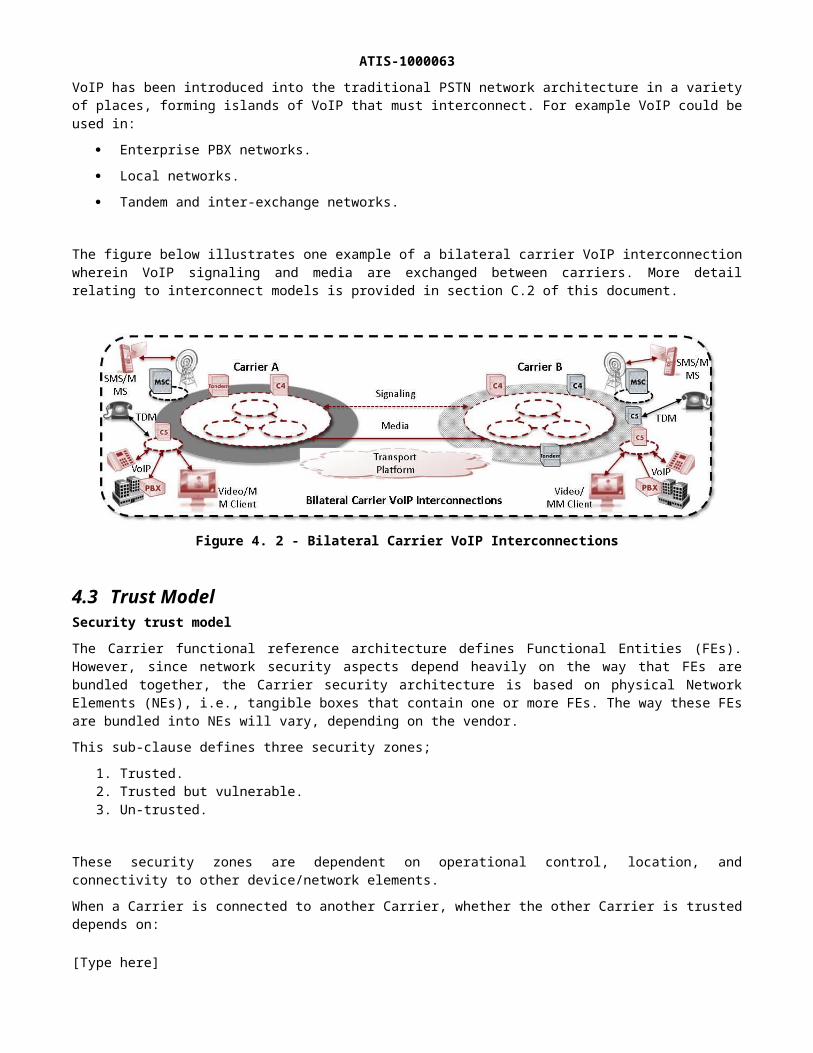
The figure below illustrates one example of a bilateral carrier VoIP interconnection wherein VoIP signaling and media are exchanged between carriers. More detail relating to interconnect models is provided in section C.2 of this document.
Figure 4. 2 - Bilateral Carrier VoIP Interconnections
4.3 Trust ModelSecurity trust modelThe Carrier functional reference architecture defines Functional Entities (FEs). However, since network security aspects depend heavily on the way that FEs are bundled together, the Carrier security architecture is based on physical Network Elements (NEs), i.e., tangible boxes that contain one or more FEs. The way these FEs are bundled into NEs will vary, depending on the vendor.
This sub-clause defines three security zones;
1. Trusted.2. Trusted but vulnerable.3. Un-trusted.
These security zones are dependent on operational control, location, and connectivity to other device/network elements.
When a Carrier is connected to another Carrier, whether the other Carrier is trusted depends on:
Physical interconnection, where the interconnection can range from a direct connection in a secure building to via shared facilities;
The peering model, whether the traffic is exchanged directly between the two Carrier service providers, or via one or more untrusted Carrier transport providers;
Business relationships, where there may be penalty clauses in the SLA agreements, and/or a trust in the other Carrier provider’s security policy. The relationship must specify contractual terms stating the obligations each party to the contract agrees to and should also specify any specific security mechanisms, information and procedures also agreed to by the parties.
In general, Carrier providers should view other providers as un-trusted. Figure 3 shows an example when a connected Carrier is judged un-trusted.
[Type here]

ATIS-1000063
Figure 4. 3 - Carrier Interconnection Trust Relationship
An “internally trusted network security zone” or “trusted zone” in short, is a zone where a Carrier provider’s network elements and systems reside and never communicate directly with customer equipment or other domains. The common characteristics of Carrier network elements in this zone are that they are under the full control of the Carrier provider are located in the Carrier provider domain, and they communicate only with elements in the “trusted” zone and with elements in the “trusted-but-vulnerable” zone. It should not be assumed that because it is in a trusted zone it is secure per se.
The “trusted zone” will be protected by a combination of various methods. Some examples are physical security of the Carrier network elements, general hardening of the systems, , use of secure signaling, security for OAMP messages separate VPN within the (MPLS/)IP network for communication within the “trusted” zone and with Carrier network elements in the “trusted-but-vulnerable” zone. See clause 8 for more details.
A “trusted but vulnerable network security zone”, or “trusted but vulnerable zone” in short, is a zone where the network elements/devices are operated (provisioned and maintained) by the Carrier provider. The equipment may be under the control by either the customer/subscriber or the Carrier provider. In addition, the equipment may be located within or outside the Carrier provider’s premises. They communicate with elements both in the trusted zone and with elements in the un-trusted zone, which is why they are “vulnerable”. Their major security function is to protect the NEs in the trusted zone from the security attacks originated in the un-trusted zone.
Elements that are located on the Carrier provider’s domain with connectivity to elements outside the trusted zone are referred to as Network Border Elements (NBEs). Examples of these are the:
Network Border Elements (NBE), which provide the User-Network Interface service control or transport elements of the Carrier provider in the trusted zone in order to provide the user/subscriber access to the Carrier provider’s network for services and/or transport.
Domain Border Element (DBE) that is the same kind of equipment with network border element except that it resides on the border between domains.
Device configuration & bootstrap NBE (DCB-NBE) that interface with the Carrier provider’s device configuration system in the trusted zone in order to configure the user’s/subscriber’s device and Carrier provider’s equipment in the outside plant.
Operations, Administration, Maintenance, and Provisioning NBE(OAMP-NBE) that interfaces with the Carrier provider’s OAMP systems in the trusted zone in order to provide and maintain the user’s/subscriber’s device and Carrier provider’s equipment in the outside plant.
[Type here]
ATIS-1000063 Application Server/Web Server NBE (AS/WS-NBE) that interfaces with the Carrier provider’s AS/WS-NBE
in the trusted zone to provide the user/subscriber access to web based services.
Examples of devices and systems that are operated by an Carrier provider but are not located on the Carrier provider’s premises, and that may or may not be under the control of the Carrier provider (and, therefore, may or may not be part of the trusted zone), are:
Outside plant equipment in the access network/technology; Base Station Router (BSR), a wireless network element that integrates the base station, radio network
controller and router functionalities;1
Optical Units (ONUs) within a user/subscriber’s residence.
The “trusted-but-vulnerable” zone will be protected by a combination of methods. Some examples are physical security of the Carrier network elements, general hardening of the systems, , use of secure signaling for all signaling messages sent to Carrier network elements in the “trusted” zone, security for OAMP messages, and packet filters and firewalls as appropriate. See clause 8 for more details.
An “un-trusted zone” includes all network elements and systems of a customer network, peer network, or other Carrier provider security zone outside of the related Carrier provider domain. These are connected to the Carrier provider’s border elements. The elements in the “un-trusted zone” may not be under the control of the Carrier providers and it is effectively impossible to enforce the provider’s security policy on the user. Still it is desirable to apply some security measures, and to that end, it is recommended that signaling, media, and OAM&P be secured and that the Terminal Equipment Border Element (TE-BE) located in the “un-trusted zone”, is hardened. However, due to the lack of physical security, these measures cannot be considered absolutely safe. See clause 8 for more details.
5 General Procedures5.1 Extension Negotiation The peering entities involved in the negotiation of the SIP extension may be the border elements themselves or an element from within the carrier networks (with the SIP signaling transited through the border elements.) Regardless of which node is responsible for the negotiation, the nature of the interconnect between the carrier networks MUST comply with the profile defined by this document.
SIP entities involved in session peering SHOULD be configured in such a way that they do not require any SIP extensions, beyond those mandated by this document, to be supported by the peer Carrier (SIP Service Provider) network. When sending an out-of-dialog request to a peer Carrier network, SIP entities involved in session peering SHOULD include a Supported header field identifying all the extensions supported by the sending network.
SIP entities involved in session peering MAY support configuration controls to disable certain extensions based on bilateral agreement between peer Carrier networks. For example, a SIP entity involved in session peering could be configured to remove ‘preconditions’ from the Supported header in order to disable the use the SIP preconditions procedures [RFC 3312].
NOTE: Policies that limit or block the use of SIP extensions should be applied with care, since their application tends to disable SIP's native extension negotiation mechanism, and therefore inhibit the deployment of new services.
When sending a dialog-initiating request to a peer Carrier network, SIP entities involved in session peering SHOULD identify all supported SIP methods in the Allow header field. In the absence of an ALLOW header, the recipient of such a message from a network claiming compliance with this profile may assume support of those methods listed as mandatory in section 7.2.
1 This is not CPE.[Type here]

ATIS-1000063
5.2 Public User IdentitiesUsers are identified at the peering interface by their Public User Identity. A SIP entity involved in session peering MUST encode Public User Identities in a SIP URI utilizing the telephone-subscriber syntax as indicated by the "user=phone" parameter (see Error: Reference source not found section 19.1.6), where the user part of the SIP URI contains a global telephone number as defined in Error: Reference source not found.
Example:
sip:[email protected];user=phone
It should be noted that not all URIs contained in messages crossing the IPNNI are addressed to users. For example messages meant to invoke special services to which N11 codes are assigned in the NANP, will carry the N11 code in the user part of the Request-URI; and MAY utilize the user=dialstring parameter as specified in RFC-4967.
5.2.1 Identifying the Called UserWhen sending a dialog-initiating or standalone request to a peer Carrier network, SIP entities involved in session peering MUST:
Identify the called user or service in the Request-URI of the request, and Identify the called user or service using a SIP URI as described above in Section Error: Reference source
not found.
In addition, if Local Number Portability (LNP) information for the called number was obtained, then SIP entities involved in session peering MUST:
Indicate that the called number was portability corrected using the Tel URI "npdi" parameter in the Request-URI as defined in Error: Reference source not found, and
if the called number is ported, identify the routing number in the Request-URI using the global form of the "rn" parameter, which is indicated by a leading "+" character followed by the country-code followed by the national number (e.g., "rn=+16132220000").
On receiving a dialog-initiating or standalone request from a peer Carrier network, SIP entities involved in session peering MUST:
identify the called user or service based on the contents in the Request-URI, where the Request-URI contains a SIP URI as described in Section 5.2.3;
Obtain the LNP data for the called number based on the presence and contents of the "npdi" and "rn" Tel URI parameters contained in the SIP URI in the Request-URI as defined in Error: Reference source notfound.
Table 5.1 summarizes the called user identity that MUST be supported at the peering interface.
Table 5. 1 - Called User Identities
Use Case
Valid Form Example
No LNP query
SIP URI containing global telephone number
sip:[email protected];user=phone
[Type here]

ATIS-1000063
Use Case
Valid Form Example
LNP Query - number not ported
Above plus "npdi" parameter
sip:+13036614567;[email protected];user=phone
LNP Query - number ported
Above plus global "rn" parameter
sip:+13036614567;npdi;[email protected];user=phone
North American supported formats are shown in Table 5.2.
5.2.2 Identifying the Calling UserWhen sending a dialog-initiating or standalone request, SIP entities involved in session peering MUST identify the verified calling user, when available, in the P-Asserted-Identity header field. When available, and the calling user is known, and the calling user has not requested anonymity, the identity MUST be included in the From header field. If the calling user has requested anonymity, the originating network MAY anonymize the content of the FROM header as specified in RFC-3261. A non-anonymized identity MUST be populated using the telephone-subscriber syntax form of the SIP URI as described above in Section 5.2.3.
5.2.3 Numbering & AddressingThe table below describes the set of URI formats that MUST be supported on the IP-NNI, and the headers in which these formats may appear. This is not intended to preclude the use of tel or sips URIs.
Table 5. 2- North American Numbering Plan formats
URI sip:+1NPANXXXXXX@host;user=phone
Description
NANP number
Reference IETF RFC3966
Headers R-URI, To, From, Request Contact, 3XX Contact, PAI, Diversion
URI sip: 8YYXXXXXXX@host
Note: may contain user=phone or dialstring
Description
NANP 8YY number
Reference IETF RFC3966
Headers R-URI, To, 3XX Contact
URI sip:+1NPANXXXXXX;npdi@host;user=phone
[Type here]

ATIS-1000063
Description
NANP number with Number Portability Dip Indicator
Reference IETF RFC 4694
Headers R-URI, To, 3XX Contact
URI sip:+1NPANXXXXXX;rn=+1NPANXXXXXX;npdi@host;user=phone
Description
NANP number with Number Portability Dip indicator and LRN
Reference IETF RFC 4694
Headers R-URI, To, 3XX Contact
URI sip:+1NPANXXXXXX;cic=+10288@host;user=phone
Description
NANP number with Carrier Identification Code, NPA may be an 8YY
Reference IETF RFC 4694
Headers R-URI, To, 3XX Contact
URI sip:+1NPANXXXXXX;oli=0@host;user=phone
Description
NANP number with OLI
Reference 3GPP TS 24.229
Headers P-Asserted-Identity
URI sip:+1NPANXXXXXX;rn=+1NPANXXXXXX@host;user=phone
Description
NANP number with JIP
Reference IETF RFC 4694
Headers From, P-Asserted-Identity, Diversion
URI sip:N11;phone-context=+1@host;
Note: may contain user=phone or dialstring
Description
NANP special service code in local number format
Reference IETF RFC3966
[Type here]
ATIS-1000063
Headers R-URI, To, 3XX Contact
URI sip:2145551212;phone-context=+1@host
Description
NANP directory assistance in local number format (for area code 214)
Reference IETF RFC3966
Headers R-URI, To, 3XX Contact
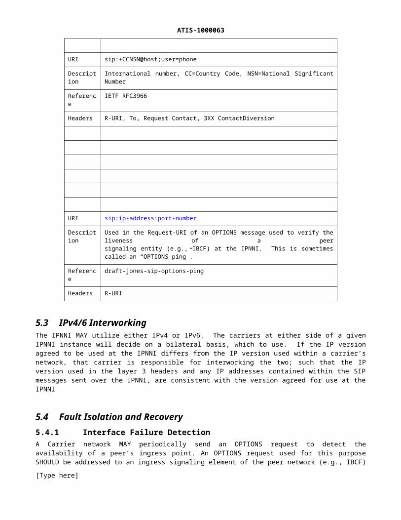
URI sip:+CCNSN@host;user=phone
Description
International number, CC=Country Code, NSN=National SignificantNumber
Reference IETF RFC3966
Headers R-URI, To, Request Contact, 3XX ContactDiversion
URI sip:ip-address:port-number
Description
Used in the Request-URI of an OPTIONS message used to verify the liveness of a peersignaling entity (e.g., IBCF) at the IPNNI. This is sometimes called an “OPTIONS ping”.
Reference draft-jones-sip-options-ping
Headers R-URI
5.3 IPv4/6 InterworkingThe IPNNI MAY utilize either IPv4 or IPv6. The carriers at either side of a given IPNNI instance will decide on a bilateral basis, which to use. If the IP version agreed to be used at the IPNNI differs from the IP version used within a carrier’s network, that carrier is responsible for interworking the two; such that the IP version used in the layer 3 headers and any IP addresses contained within the SIP messages sent over the IPNNI, are consistent with the version agreed for use at the IPNNI
5.4 Fault Isolation and Recovery5.4.1 Interface Failure DetectionA Carrier network MAY periodically send an OPTIONS request to detect the availability of a peer’s ingress point. An OPTIONS request used for this purpose SHOULD be addressed to an ingress signaling element of the peer network (e.g., IBCF) using a URI in the format sip:hostport in the Request-URI; and SHOULD have max-forwards set to ‘1’. The rate at which such requests are sent is based on bi-lateral agreement.
[Type here]

ATIS-1000063A SIP element receiving such a request MUST respond with a 200 OK if it is willing and able to process SIP messages from the sender. A SIP element unable to process SIP messages SHOULD return a 503 response. The response MAY include a Retry-After header.
A SIP element MAY inhibit its sending of such requests to a given peer element if it detects that other traffic is being successfully exchanged with that element. However there is value in continuing to send OPTIONS messages even in the presence of other traffic, as it allows the sending element to learn that its peer is nearing overload or has been placed into a maintenance state in which new session requests are likely to be rejected.
If a requesting entity fails to receive a response to an OPTIONS request, it MAY retransmit that message following the procedures defined in RFC 3261. If a requesting SIP entity receives a 486 or 503 response it can send subsequent OPTIONS messages in order to detect a change in operational status, but it SHOULD, as per RFC 3261, honor the Retry-After header field received in the previous response.
The sending element SHOULD, after receipt of a 486 response, attempt to avoid establishing new sessions with the heavily loaded peer element until receiving a 200 OK to a subsequent OPTIONS request. It MUST, after receipt of a 503 response, avoid establishing new sessions with the peer element until receiving a 200 OK to a subsequent OPTIONS request. If the sending Carrier network fails to receive a response to N consecutive OPTIONS requests, it MUST behave as if a 503 response had been returned. ‘N’ is an implementation specific parameter that SHOULD be subject to configuration by the carrier.
5.4.2 Congestion ControlCarriers MUST2 support SIP Overload Control including support of the default algorithm [RFC 7339]. Carrier's MAY optional support the Rate Based algorithm based on bilateral agreement between two carriers.
A Carrier network MAY impose limits on the number of simultaneous calls, and the incoming rate at which it will accept calls, at a given IPNNI instance. On receiving a dialog-initiating request that exceeds such limits, the receiving Carrier network MAY respond with a 503 (Service Unavailable) response without the Retry-After header as indicated by RFC 7339.
On receiving a 503 (Service Unavailable) response from a peer Carrier network, the receiving Carrier network MUST process the response per IETF RFC 3261.
5.4.3 Session TimerSIP entities involved in session peering SHOULD support Session Timer as defined in Error: Reference sourcenot found.
5.4.4 RTP Loopback TestPeer Carrier networks SHOULD support the RTP Loopback Test procedures defined in Error: Reference sourcenot found. Carrier networks that support the RTP Loopback procedures will provide a SIP URI that identifies a media endpoint within the Carrier network that performs the loopback functions. Ideally, this "loopback" media endpoint would be located near the ingress point of the peer Carrier network.
5.5 Media Transport5.5.1 RTP5.5.2 CodecsNarrow Band codecs encode the same frequency range as is used in the PSTN. The following codecs, widely used in IP based voice networks, shall be supported as described in the tables below. Codecs in the Group 1
2 Support of SIP Overload Control was defined for in the IETF for 3GPP Release 11, and may not be available for deployment at the time of this documents initial publication.[Type here]

ATIS-1000063column in each table MUST be supported for both transmission and reception across the NNI. Codecs in the Group 2 columns in each table SHOULD be supported for both transmission and reception across the NNI.
Table 5.3 - Mandatory and Optional Narrow Band Codecs
Group 1. Mandatory Narrow Band codecs Group 2. Optional
G.711 μ-law 64 kbit/s G.711 A-law
G.723.1
G.726, G.729, G.729a, G.729b, G.729ab 8kbit/s
AMR-NB
When wide band audio is being used, the following codecs shall be supported as described in the tables below. Codecs in the Group 1 column MUST be supported for both transmission and reception across the NNI. Codecs in the Group 2 column SHOULD be supported for both transmission and reception across the NNI.
Table 5.4 - Mandatory and Optional Wideband Codecs
Group 1. Mandatory Wideband codecs Group 2. Optional Wideband codecs
G.722 (generally used by fixed network operators)
G.722.2 (AMR-WB, generally used by mobile network operators)
5.5.3 Codec/Packetization Period Use & Transcoding GuidelinesThe packetization periods and payload types shown in the following table MUST be supported for each of the associated codecs.
Codec Packetization Period Payload type definition
G.711 A-law 20 ms PT= 8 Static
G.711 μ-law 20 ms PT= 0 Static
G.729, G.729a, 20 ms PT= 18 Static
G.729b, G.729ab 20 ms PT= 18 Static. Optional parameter “annexb” may be used according to RFC 4855
G.723.1 30 ms PT=4 Static Optional parameters "annexa" and "bitrate" may be used according
to RFC3555
G.726 20 ms PT=Dynamic as defined in RFC 4855
[Type here]

ATIS-1000063
Codec Packetization Period Payload type definition
AMR-NB 20 ms Dynamic as defined in RFC 4867
G.722 20 ms PT=9 Static
AMR-WB 20 ms Dynamic as defined in RFC 4867 Error: Reference source notfound
G.722 shall be supported at a bit rate of 64 kbit/s.
5.5.4 General GuidelinesThe following general guidelines aim to provide default rules for codec choice and transcoding responsibility:
1. Transcoding SHOULD generally avoided; 2. If the SDP offerer supports the wideband codec(s), then the wideband codec SHOULD be placed first in
order (e.g., if wideband and narrowband are offered, the wideband is first in order). 3. Wideband codec continuity (Transcoder Free Operations) offers the optimal quality; Service Providers
MUST offer a fallback to narrowband codec that is universally supported (e.g. G.711). 4. Transcoding to narrowband codecs MUST be avoided unless it is the only way for a call to be
successfully established;5. The order of codec/packetisation period preference is determined by the originating terminal and
SHOULD be honoured wherever possible; 6. If the call is to be routed to a TDM network, only one transcoding is recommended. If required, it SHOULD
be performed during the voice over IP/TDM conversion;in case no common codec can be used between both end Service Providers, in the first instance it is the responsibility of Service Providers to support transcoding in order to ensure successful voice interoperability for their services
5.5.5 Voice-band Data Transport MechanismsVoice-band data (VBD) includes modem and fax data traditionally carried in circuit-switched voice channels. In a VoIP environment, the presence of VBD sessions will typically come from interworking with circuit-switched networks and CPE. Either packetized G.711 µ-law or A-law or packet-optimized relay mechanisms such as [T.38] fax relay can be used to carry these data streams. Modem relay modes such as in [V.150.1] are not common in the inter-carrier environment. Where NNIs use IP transport engineered for low loss and jitter, VBD without fax/modem relay should normally be sufficient. In the case of VBD without relay mechanisms, VBD may be transparently used over a compatible audio codec. Fax relay modes or explicit VBD-mode negotiation can optionally be used by bilateral agreement.
SIP entities involved in session peering MUST support fax or modem voice-band data (VBD) pass-through in a G.711 µ-law or A-law audio stream.
When a non-G.711 codec is originally negotiated for a session, SIP entities involved in session peering MUST support fallback to G.711 µ-law or A-law for VBD pass-through via SDP audio codec renegotiation without explicit VBD-mode negotiation. It is up to bilateral agreement which network element or elements will be responsible for recognizing fax/modem tones and for initiating a transition.
SIP entities involved in session peering MAY use fax relay mechanisms such as [T.38].
SIP entities involved in session peering MAY use explicit negotiation of transitions to VBD modes such as the following methods:
Negotiation of support of voice-band data as specified in [V.152] Modem/fax events as specified in [RFC 4733]
[Type here]
ATIS-1000063
5.5.6 DTMF Digit Transport MechanismsThe “named telephone events,” or “telephone-events” RTP payload [RFC 4733] is the preferred mechanism for transport of DTMF digit events between VoIP endpoints and network elements. by bilateral agreement, in-band DTMF tones might be used across the NNI to avoid transcoding from in-band DTMF tones to named telephone events (DTMF relay), for instance if the media stream is expected to originate and terminate on circuit-switched voice channels in both carrier networks. It is assumed that in-band DTMF is only applicable for sessions using the G.711 codecs. The “telephone-events” payload type is negotiated by offering it along with an audio codec in the SDP. If the telephone-events payload is not negotiated, it is assumed that any DTMF digits will be passed across the NNI as in-band tones in the audio RTP channel.
SIP entities involved in session peering MUST support DTMF digits in a named telephone events RTP payload [RFC 4733].
SIP entities involved in session peering MAY support DTMF digits as in-band tones when the negotiated audio codec is G.711 A-law or µ-law.
SIP entities involved in session peering that utilize named telephone events [RFC 4733] for DTMF digit transport MUST support at least the following events (event codes 0-11):
digits 0-9 ‘#’ (pound or hash) ‘*’ (star)
5.6 IP Packet MarkingThe following table describes the traffic classes defined for use across the NNI
Traffic class Traffic typeVoice Media Speech / Voice bearer.
Voice Signaling Voice Control Traffic (SIP signaling protocol)
Other Customer Traffic Internet traffic, other data traffic
Other control/management traffic such as BGP traffic may also use the interface.
Distinguishing traffic classesIn order to distinguish between traffic classes, the use of the DSCP marking scheme in Behaviour Aggregation mode Error: Reference source not found is recommended.NOTE: Using classification based on the DSCP value, packet marking is pre-agreed by both operators. The receiving operator assumes that the sending operator has marked the packet correctly according to the pre-agreed scheme described above.
If there is a mix of Internet and VoIP traffic across the interconnection or the recommended marking cannot be guaranteed, an alternative solution is to classify packets using the Multi-Field classification method Error:Reference source not found. Using this scheme, ingress traffic is classified by the receiving Operator PE Router based on any field in the IP header, e.g. destination address, source address, port numbers or other IP packet header fields.
It should be the non-standard service provider’s responsibility to re-mark packets to the standard values, both on and off the interconnecting link. This would be consistent with ITU-T Recommendation Y.1566, QoS and Mapping and Interconnection [http://www.itu.int/rec/T-REC-Y.1566-201207-I] and encourage adoption of the packet
[Type here]

ATIS-1000063marking requirements in the interconnection spec (support of the spec means offering a single set of class markings to all interconnecting parties, regardless of their internal network markings).
IP Marking tableThe following table illustrates DiffServ IETF RFC and IP Precedence TOS marking scheme plus the coding scheme at the MPLS and Ethernet layers that SHOULD be supported, respectively. It applies to all the traffic to be transmitted.
Traffic Type DSCP Marking IP Precedence
802.1Q VLAN
Voice Signaling and Media
DSCP 46/EF (101110).5 5
DSCP 46/EF (101110) or DSCP 00/DF (000000).
5or0
5or0
ETS Voice Signaling and Media
DSCP 44/VOICE-ADMIT (101100).
5 5
DSCP 44/VOICE-ADMIT (101100).
5 5
Other traffic DSCP 00/DF (000000). 0 0
The marking for the other control/management traffic depends on the specific network implementation.
Traffic treatmentVoice and media traffic leaving the sending Border Function towards the receiving Border Function should be treated according to the Expedited Forwarding Per-Hop Behavior Error: Reference source not found, Error:Reference source not found.ETS voice signalling and media traffic leaving the sending Border Function towards the receiving Border Function should be treated according to the VOICE-ADMIT Forwarding Per-Hop Behaviour [Reference to 5865].Voice signaling traffic leaving the sending Border Function towards the receiving Border Function should be treated according to the Expedited Forwarding Per-Hop Behavior [RFC 3246]Error: Reference source not found, [RFC3247], or alternatively according to the Default Forwarding Per-Hop Behavior [RFC 2597].Signalling traffic leaving the sending Border Function towards the sending PE router MUST be treated according to one of the following schemes:
the Expedited Forwarding Per-Hop Behavior, as specified in RFC 3246 and RFC 3247; the Assured Forwarding Per-Hop Behavior as specified in RFC 2597; the Default forwarding PHB , as specified in IETF RFC 2597.
6 Call Features6.1 Basic Call SetupThis section describes the procedures at the peering interface required to establish a 2-way session for a basic voice call. In this case it is assumed that no originating or terminating features are applied (no call blocking, forwarding, etc), and that the called line is available to accept the call. Also, this section describes the session establishment procedures when the call is initiated by the originating SIP User Agent itself, and not via a 3rd party in support of features like click-to-call. SIP entities involved in session peering MUST support the SDP offer/answer procedures specified in Error: Reference source not found with the consideration that reliable provisional responses MUST be used as specified in [RFC 3262] when a provisional response contains SDP. The originating Carrier network SHOULD include an SDP offer in the initial INVITE. The terminating Carrier network
[Type here]

ATIS-1000063MUST include an SDP answer in a reliable response to an INVITE received with an SDP offer. The terminating Carrier MUST include an SDP offer in the first reliable response to an INVITE received without an SDP offer. Once an SDP answer has been provided in a reliable response, it SHOULD not be repeated in subsequent responses (e.g., 200 OK (INVITE)) within that dialog, but if it is, the SDP in the 200 OK (INVITE) MUST be identical to the SDP in the reliable response.
The terminating Carrier network MAY also include SDP message bodies in provisional 18x responses, final responses, UPDATE requests, in-dialog INVITE requests or PRACK requests.
NOTE: If the provisional and final responses are on different dialogs (say, when the INVITE is forked), the SDP may be different between the various responses.
SIP entities involved in session peering that advertise support for different but overlapping sets of codecs in the SDP offer/answer exchange for a given call MUST negotiate a single common codec for the call. An SDP answer MUST contain only a single codec (plus additional auxiliary payload types such as telephone-event), per media stream, selected from the offered set of codecs.
6.1.1 SDP RequirementsSIP entities involved in session peering MUST comply with the SDP requirements defined in Error: Referencesource not found. A SIP entity involved in session peering MUST include only one media (m=) description per desired media stream in an SDP offer to a peer Carrier network.
If a SIP entity involved in session peering receives an SDP offer containing multiple media descriptions, it MUST act on the media descriptions and include all of them in the same order in the response, including non-zero ports and zero ports for the offered media according to its capabilities as specified in Error: Reference source not found. A SIP entity involved in session peering MUST NOT reject an offered session because it offers more media than the SIP entity can handle.
6.2 Ringback Tone vs. Early MediaWhile the originating Carrier network is waiting for the terminating Carrier network to answer the call, in the case of when a single early dialog is created, the originating line is either playing local ringback tone to the calling user, or is connected to a receive-only or bi-directional early-media session with the terminating Carrier network. For example, early media can be supplied by a network element in the terminating network (e.g., custom ringback tone) while the terminating network alerts the called user.
SIP entities involved in session peering MUST use the following procedures to control whether the originating line applies local ringback tone or provides remotely generated media to the calling user.
1. The terminating Carrier network controls the application of local ringback tone at the originating line or the establishment of an early media session by sending the following provisional response to a call-initiating INVITE.
The terminating Carrier Network MUST send a 180 (Ringing) response to the originating network, if the call scenario requires the application of local ringback tone at the originating line.
o If the INVITE did not contain an SDP offer, and the 180 Ringing response is sent reliably, the 180 Ringing response MUST contain an SDP offer.
o If the INVITE contained an SDP offer, and the terminating network intends that the originating network apply local ringback tone, the terminating network SHOULD NOT include an SDP answer in the 180 Ringing response.
The terminating Carrier Network MUST reliably send a provisional response containing an SDP answer if the call scenario requires the terminating network to provide, and the originating network to play to the calling user, early media generated by the terminating network.
2. NOTE: If the terminating network receives an INVITE that does not contain an SDP offer, and wishes to provide early media to the calling user, it must establish the session over which to do so via an UPDATE request sent after the initial offer / answer exchange has concluded.The originating Carrier network performs the following action on receipt of a provisional response to a call-initiating INVITE.
The originating Carrier network MUST apply local ringback tone if it receives a 180 (Ringing) response containing no SDP.
[Type here]

ATIS-1000063 The originating Carrier network MUST establish an early media session with the media endpoint
described by the SDP when it receives a 18x response containing SDP.The originating Carrier Network MUST maintain current early media state (e.g., continue to apply local ringback tone if it was already being applied when the response was received) if it receives a 18x response other than 180 (Ringing), and the response contains no SDP.
When establishing an early media session, the originating Carrier network MAY immediately remove any local ringback tone currently being applied. Alternatively, the originating Carrier network MAY wait for receipt of RTP that matches the received SDP, and apply other checks/policies to validate the received RTP, before removing any locally applied ringback tone.
6.3 Early-Media Carriers SHOULD support P-Early-Media as defined in [RFC 5009].
6.3.1 Terminating Network ProceduresWhen sending an 18x response to an INVITE request with the intent of providing early media, the terminating network MUST include a P-Early-Media header field, as defined in IETF RFC 5009, authorizing early media, except when:
A message including a P-Early-Media header field has already been sent and the most recently sent P-Early-Media header field authorization matches that which would be sent, or
P-Early-Media is not supported by the terminating network.
If the terminating network supports P-Early-Media but the request did not indicate that P-Early-Media is supported by the originating network (i.e., did not contain P-Early-Media: supported) the inclusion of P-Early-Media headers in responses to this request is determined by policies in the terminating network. Such policies MAY be subject to bilateral agreement.
When both-way early media is to be authorized, and P-Early-Media is supported by the terminating network, the 18x response shall include a P-Early-Media header field authorizing backward and forward early media (i.e., "sendrecv"),
When early media only in the direction from terminating toward originating network is to be authorized, and P-Early-Media is supported by the terminating network, the 18x response shall include a P-Early-Media header field authorizing backward early media (i.e., "sendonly").
When early media only in the direction from originating toward terminating network is to be authorized, and P-Early-Media is supported by the terminating network, the 18x response shall include a P-Early-Media header field authorizing forward early media (i.e., "recvonly").
When early media will not be present, or to indicate that previously authorized early media is no longer authorized and/or will no longer be sent, and P-Early-Media is supported by the terminating network, the 18x response shall include a P-Early-Media header field not authorizing early media (i.e., “inactive”).
In the event that the nature of early media changes after initially signaled in an 18x response, the new authorization SHOULD be signaled in the P-Early-Media header field of either a subsequent message. Alternatively, the procedures described in 6.4 may be used.
6.3.2 Originating Network ProceduresWhen sending the initial INVITE request a SIP entity involved in session peering that supports P-Early-Media shall include the P-Early-Media header field with the “supported” value to indicate applicability of the P-Early-Media procedures, per IETF RFC 5009.
[Type here]

ATIS-1000063When a message is received containing a P-Early-Media header field, with parameter {sendonly, recvonly, sendrecv or inactive}, and the UAC supports P-Early-Media, then the following through connection procedures shall occur.
If a P-Early-Media header field is received authorizing backward early media (i.e., a value of "sendonly"), then through connection in the backward direction shall be performed, if not already done.
If a P-Early-Media header field is received not authorizing early media (i.e., a value of "inactive"), then through connection shall not be performed or removed if already done. The originating network shall generate alerting if a 180 Ringing response has been received.
If a P-Early-Media header field is received authorizing both backward and forward early media (i.e., a value of "sendrecv"), then through connection in both directions shall be performed. The bearer path shall be connected in both directions on completion of the bearer setup.
If a P-Early-Media header field is received authorizing forward early media (i.e., a value of "recvonly"), then through connection in the forward direction shall be performed, if not already done.
6.4 Forking the INVITESometimes the terminating network delivers a request to multiple end points. Such an action may be taken by a SIP proxy, due to the called party number being registered at multiple devices. RFC-3261 defines this as “forking”. Other actions taken at the application layer (e.g., call diversion to voicemail) can have similar effects.
Each end point MAY reply to the request. If it does it MAY append a “tag” to the TO header field, identifying a unique dialog between itself and the originating user agent.
By default the IPNNI delivers the resulting multiple dialogs to the originating network, with the expectation that the originating network will resolve them according to local policy. Alternatively, with bilateral agreement, the terminating network MAY consolidate these responses into a single dialog toward the originating network.
There is at present no standardized way to request (in the signaling message) such treatment.
6.5 Redirecting the INVITECarrier's MAY support redirection across the NNI, based on bilateral agreement. The redirection MAY be performed with a 3XX or REFER message.
6.6 Establishing Calls Using 3PCCCarriers may support features such as click-to-call, where the call is initiated by a 3 rd party such as an Application Server on behalf of the originating user. To support such features, SIP entities involved in session peering MUST support the 3PCC procedures described in Error: Reference source not found.
6.7 Call HoldA SIP entity involved in session peering that wishes to place a media stream "on hold" MUST offer an updated SDP to its peer Carrier network with an attribute of "a=inactive" or "a=sendonly" in the media description block. A SIP entity involved in session peering that wishes to place a media stream "on hold" SHOULD NOT set the connection information of the SDP to a null IP address. For example, the SIP entity involved in session peering SHOULD NOT set the 'c=' connection line to c=IN IP4 0.0.0.0. A SIP entity involved in session peering that wants to place a media stream "on hold" SHOULD locally mute the media stream. A session entity involved in session peering MUST, however, be capable of receiving SDP whose connection address indicates a NULL IP address; interpreting this as a directive to send neither RTP nor RTCP to the peer [RFC3264].
Note: devices that require receiving RTP or RTCP may drop the call/session in this instance.
A SIP entity involved in session peering that receives an SDP offer with an attribute of "a=inactive" in the media block MUST place the media stream "on hold" and send an SDP answer containing a media attribute of
[Type here]
ATIS-1000063"a=inactive". A SIP entity involved in session peering that receives an SDP offer with an attribute of "a=inactive" in the media block SHOULD NOT set the connection data of the answer SDP to c=0.0.0.0.
6.8 Calling Number & Name DeliveryThe originating Carrier network MAY provide the calling number of the originating user in the P-Asserted-Identity header field of dialog-initiating requests. (The mechanism for obtaining the calling name is outside the scope of this document.)
If the originating user wants to remain anonymous, the originating Carrier network MUST include a Privacy header field containing the value "id" or “user” as specified in Error: Reference source not found and Error: Referencesource not found. In addition, the originating Carrier network SHOULD obscure the identity of the originating user in other header fields as follows:
Set the identity information in the From header field to "Anonymous <sip:[email protected]>"
The terminating Carrier network MAY obtain the calling name and number for caller-ID display from the contents of the P-Asserted-Identity header field contained in dialog-initiating requests. If the INVITE request contains a Privacy header with the value "id" or “user”, the terminating Carrier network MUST NOT reveal the calling user’s name or telephone number to the terminating user.
6.9 Call ForwardingCarrier's MUST support the History-Info Header and SHOULD support of the SIP Diversion header. When both headers are sent, the sender MUST ensure that they are semantically identical.
If the History-Info header and the Diversion header are both received by a carrier supporting both headers, the terminating network may process whichever it prefers.
If a Carrier offers call-forwarding services to its users, then the forwarding Carrier network MAY remain in the signaling path of the forwarded call in order to support separate billing for forward-from and forward-to legs. A Carrier network that is required to remain in the signaling path of a forwarded call based on local policy MUST do so using one of the following procedures:
1. forward the INVITE to the forward-to-user while remaining in the signaling path as a SIP Proxy or B2BUA, or
6.10 National Security/Emergency Prepardness (NS/EP)Resource Priority Header (RPH) MUST be supported by NS/EP compliant networks, and MUST be transparently passed by non-NS/EP compliant networks.
7 NNI Signaling Profile7.1 SIP Methods & Header FieldsNotations of the codes
For the purpose of the present document clause 6.1.1.4 TS 29.165 v11.5.0 (2012-12) applies as follows:
In the Table 7.1 the status codes "m", "o", "c" and "n/a" have the following meanings:
[Type here]

ATIS-1000063
Table 7. 1 - Key to notation codes for SIP messagesNotation
codeNotation name Sending side Receiving side
m mandatory The message shall be supported at NNI.Supporting sending a SIP message at the NNI means that this message shall be sent over the NNI if received from the serving network. It does not imply that network elements inside the serving network or user equipment connected to this network shall support this message.
Supporting receiving a SIP message at the NNI means that this message shall be forwarded to the serving network. It does not imply that network elements inside the served network or user equipment connected to this network are supporting this message.
o optional The message may or may not be supported at NNI. The support of the method is provided based on bilateral agreement between the operators.
Same as for sending side.
n/a not applicable It is impossible to use/support the message.
It is impossible to use/support the message. This message will be discarded by the IBCF.
c <integer>
conditional The requirement on the message ("m", "o" or "n/a") depends on the support of other optional or conditional items. <integer> is the identifier of the conditional expression.
Same as for sending side.
7.1.1 SIP MethodsFor the purpose of the present document clause 6.1.1.2 TS 29.165 v11.5.0 (2012-12) with the following changes applies.
3GPP TS 24.229 defines the methods allowing an IBCF to interconnect to an IBCF placed in another IM CN subsystem.
The following SIP methods are supported on the NNI as defined in Table 7.2
The following table is based on table A.5 and table A.163 of 3GPP TS 24.229 and endorsed for this document:
[Type here]

ATIS-1000063
Table 7. 2 - Supported SIP methodsItem Method Ref. IP-NNI
Sending
Receiving
1 ACK request IETF RFC 3261 [13] m m2 BYE request IETF RFC 3261 [13] m m3 BYE response IETF RFC 3261 [13] m m3 BYE response IETF RFC 3261 [13] m m4 CANCEL request IETF RFC 3261 [13] m m5 CANCEL response IETF RFC 3261 [13] m m5A INFO request IETF RFC 6086 [39] o o5B INFO response IETF RFC 6086 [39] o o8 INVITE request IETF RFC 3261 [13] m m9 INVITE response IETF RFC 3261 [13] m m9A MESSAGE request IETF RFC 3428 [19] o o9B MESSAGE response IETF RFC 3428 [19] o o10 NOTIFY request IETF RFC 3265 [20] o o11 NOTIFY response IETF RFC 3265 [20] o o12 OPTIONS request IETF RFC 3261 [13] x1 x1
13 OPTIONS response IETF RFC 3261 [13] x1 x1
14 PRACK request IETF RFC 3262 [18] m m15 PRACK response IETF RFC 3262 [18] m m15A PUBLISH request IETF RFC 3903 [21] o o15B PUBLISH response IETF RFC 3903 [21] o o16 REFER request IETF RFC 3515 [22] o o17 REFER response IETF RFC 3515 [22] o o18 REGISTER request IETF RFC 3261 [13] n/a n/a19 REGISTER response IETF RFC 3261 [13] n/a n/a20 SUBSCRIBE request IETF RFC 3265 [20] o o21 SUBSCRIBE response IETF RFC 3265 [20] o o22 UPDATE request IETF RFC 3311 [23] m m23 UPDATE response IETF RFC 3311 [23] m mNOTE: In the above table, m, o and c and n/a have the meanings indicated in table 7.1.x1: Support of OPTIONS in a SIP dialog is mandatory, where support of OPTIONS out of a SIP dialog is optional. Use of OPTIONS outside the dialogue may be used as a keep alive mechanism only based on bilateral agreement.
7.1.2 SIP Header Fields7.1.2.1 GeneralFor the purpose of the present document clause 6.1.1.3.0 of TS 29.165 v11.5.0 (2012-12) applies as follows:
[Type here]

ATIS-1000063The IBCF shall provide the capabilities to manage and modify SIP header fields according to subclause 5.10 and Annex A of 3GPP TS 24.229 with modifications as described in the following subclauses.
7.1.2.2 Trust & No Trust RelationshipFor the purpose of the present document clause 6.1.1.3.1 of TS 29.165 v11.5.0 (2012-12) applies with the following changes of Table 7.3 as follows:
The IBCF acting as exit point applies the procedures described in clause 5.10.2 of 3GPP TS 24.229 before forwarding the SIP signalling to the IBCF acting as entry point. The IBCF acting as entry point applies the procedures described in clause 5.10.3 of 3GPP TS 24.229.
Additionally, in case there is no trust relationship between the two IM CN subsystems connected by NNI, the IBCF acting as exit point applies the procedures described in clause 4.4 of 3GPP TS 24.229, before forwarding the SIP signalling.
These procedures may be utilized on a per header field basis to realize overall trust as well as per service level screening of header fields. Trust relationships and trust domains may be defined by inter-operator agreements for individual services and/or individual SIP header fields.
The management of the SIP header fields (if present) over NNI in case of a presence or not of a trust relationship between the two interconnected IM CN subsystems is wrapped up in the following table.
Table 7. 3 - Management of SIP header fields over NNI in presence or not of a trust relationshipItem Header field Reference
1 P-Asserted-Identity IETF RFC 3325 [44]2 P-Access-Network-Info
(NOTE 1)IETF RFC 3455 [24]
3 Resource-Priority IETF RFC 4412 [78]4 History-Info RFC 4244 [25]5 Reason (in a response) IETF RFC 6432
[49]6 P-Early-Media IETF RFC 5009 [74]
NOTE 1: This header field is only applicable on a roaming NNI whereas for the interconnect NNI it is left unspecified.
7.1.2.3 Derivation of Applicable SIP Header Fields from 3GPP TS 24.229For the purpose of the present document clause 6.1.1.3.2 of TS 29.165 v11.5.0 (2012-12) applies as follows:
For any method in table 7.1, the SIP header fields applicable on the NNI are detailed in the corresponding method tables for the UA role and proxy role sending behavior in Annex A of 3GPP TS 24.229. Unless other information is specified in the normative part of the present specification, the applicability of header fields at the NNI can be derived for each method from the corresponding tables in annex A of 3GPP TS 24.229 as follows:
- All header fields not present in the corresponding tables in Annex A of 3GPP TS 24.229 or marked as "n/a" in both the "RFC status" and "profile status" columns for the UA role and proxy role sending behaviour of that tables are not applicable at the NNI.
NOTE 1: Operators could choose to apply header fields for other SIP extensions on an NNI based on bilateral agreements, but this is outside the scope of the present specification.
- All header fields which are marked as "o" in at least one of the "RFC status" or the "profile status" profile columns for the sending behaviour in the corresponding UA role and proxy role tables in annex A of 3GPP TS 24.229 [5] and as "n/a" or "o" in the other such columns are applicable at NNI based on bilateral agreement between operators.
[Type here]

ATIS-1000063- All header fields which are marked as "m" in at least one of the "RFC status" or the "profile status" columns
for the sending behaviour in the corresponding UA role or proxy role table in annex A of 3GPP TS 24.229 and as "n/a", "o", or "m" in the other such columns are applicable at the NNI.
- If conditions are specified, they are also applicable at the NNI and the above rules are applicable to the "n/a", "o" and "m" values within the conditions.
NOTE 2: In the above rules, the RFC profile columns are taken into account in order to enable interworking with non-3GPP networks,
7.1.2.4 Applicability of SIP Header Fields on a Non-Roaming NNIFor the purpose of the present document clause 6.1.1.5 of TS 29.165 v11.5.0 (2012-12) applies as follows:
The following SIP header fields are only applicable on a non-roaming NNI or for the loopback traversal scenario:
- P-Refused-URI-List
7.1.2.5 Modes of SignallingEnbloc signaling MUST be supported.
7.1.3 SDP Protocol7.1.3.1 GeneralFor the purpose of the present document clause 6.1.2.1 of TS 29.165 v11.5.0 (2012-12) applies as follows:
The functional entity closest to the border of an NNI (see reference model in Clause 5) shall provide the capabilities specified for that network element in Annex A.3 of 3GPP TS 24.229.
The SDP bodies shall be encoded as described in IETF RFC 3261 and in IETF RFC 4566. The offer/answer model with the SDP as defined in IETF RFC 3264 shall be applied.
7.1.4 Major CapabilitiesFor the purpose of the present document clause 6.1.3 of TS 29.165 v11.5.0 (2012-12) applies with the following changes in Table 7.4 and Table 7.5. as follows:
This subclause contains the major capabilities to be supported over the NNI.
The table 7.4 specifies which capabilities are applicable for NNI. The profile status codes within table 7.4 are defined in table 6.1.3.2. For the "Basic SIP" capabilities part of table 6.1.3.1, the last column "Profile status over NNI" specifies the general status of applicability of the IETF RFC 3261 main mechanisms described in the 2 nd
column "Capability over the Ici".
For the "Extensions to basic SIP" capabilities part, the last column "Profile status over NNI" specifies the general status of applicability of the RFC referenced in the 2nd column "Capability over the Ici". If necessary, the applicability of RFCs at the NNI level is further detailed in the present Technical Specification.
The columns "Reference item in 3GPP TS 24.229 for the profile status" provide informative references for comparison purposes into the UA and Proxy role major capabilities tables in 3GPP TS 24.229, where the capabilities are defined via additional references.
[Type here]

ATIS-1000063Table 7. 4 - Major capabilities over NNI
[Type here]

ATIS-1000063Item Capability over the Ici Profile
status over IP-NNI
Basic SIP (IETF RFC 3261)1 registrations n/a2 initiating a session m3 terminating a session m4 General proxy behaviour n/a5 Managing several responses due to forking m6 support of indication of TLS connections in the Record-Route header n/a7 Support of authentication n/a8 Timestamped requests (Timestamp header field) m9 Presence of date in requests and responses (Date header field) m10 Presence of alerting information data (Alert-info header field) o11 Support and handling of the Require header field for REGISTER and other requests or
responses for methods other than REGISTERm
12 Support and reading of the Supported and Unsupported header fields m13 Support of the Error-Info header field in 3xx - 6xx responses o14 Support and handling of the Organization header field m15 Support and handling of the Call-Info header field m16 Support of the Contact header field in 3xx response m16A Proxy reading the contents of a body or including a body in a request or response n/a
Extensions to basic SIP16B 3GPP TS 24.237: proxy modifying the content of a body n/a17 IETF RFC 6086: SIP INFO method and package framework o17A IETF RFC 6086: legacy INFO usage o18 IETF RFC 3262 : reliability of provisional responses in SIP (PRACK method) m19 IETF RFC 3515: the SIP REFER method o20 IETF RFC 3312 and RFC 4032: integration of resource management and SIP
(Preconditions framework)o
21 IETF RFC 3311: the SIP UPDATE method m22 IETF RFC 3313: SIP extensions for media authorization (P-Media-Authorization header
field)o
23 IETF RFC 3265: SIP specific event notification (SUBSCRIBE/NOTIFY methods) o24 IETF RFC 3327: session initiation protocol extension header field for registering non-
adjacent contacts (Path header field)n/a
25 IETF RFC 3325: private extensions to the Session Initiation Protocol (SIP) for network asserted identity within trusted networks
c4
26 IETF RFC 3325: the P-Preferred-Identity header field extension n/a27 IETF RFC 3325: the P-Asserted-Identity header field extension c428 IETF RFC 3323: a privacy mechanism for the Session Initiation Protocol (SIP) (Privacy
header field)m
29 IETF RFC 3428: a messaging mechanism for the Session Initiation Protocol (SIP) (MESSAGE method)
o
30 IETF RFC 3608: session initiation protocol extension header field for service route discovery during registration (Service-Route header field)
n/a
31 IETF RFC 3486: compressing the session initiation protocol n/a32 IETF RFC 3455: private header extensions to the session initiation protocol for the 3rd-
Generation Partnership Project (3GPP) o
32A IETF RFC 3325: act as first entity within the trust domain for asserted identity n/a32B IETF RFC 3325: act as entity within trust network that can route outside the trust network n/a32C IETF RFC 3325: act as entity passing on identity transparently independent of trust n/a
[Type here]

ATIS-1000063Item Capability over the Ici Profile
status over domain
[Type here]

ATIS-1000063Item Capability over the Ici Profile
status over 33 IETF RFC 3455: the P-Associated-URI header field extension n/a34 IETF RFC 3455 [24]: the P-Called-Party-ID header field extension n/a35 IETF RFC 3455 [24]: the P-Visited-Network-ID header field extension n/a36 IETF RFC 3455 [24]: the P-Access-Network-Info header field extension c437 IETF RFC 3455 [24]: the P-Charging-Function-Addresses header field extension n/a38 IETF RFC 3455 [24]: the P-Charging-Vector header field extension m39 IETF RFC 3329 [47]: security mechanism agreement for the session initiation protocol n/a39A draft-dawes-dispatch-mediasec-parameter-03 [137]: Capability Exchange for Media
Plane Securityn/a
40 IETF RFC 3326 [48]: the Reason header field for the session initiation protocol o41 IETF RFC 6432 [49]: carrying Q.850 codes in reason header fields in SIP (Session
Initiation Protocol) responsesc4
42 IETF RFC 3581 [50]: an extension to the session initiation protocol for symmetric response routeing
o
43 IETF RFC 3841 [51]: caller preferences for the session initiation protocol (Accept-Contact, Reject-Contact and Request-Disposition header fields)
m
44 IETF RFC 3903 [21]: an event state publication extension to the session initiation protocol (PUBLISH method)
o
45 IETF RFC 4028 [52]: SIP session timer (Session-Expires and Min-SE headers) m46 IETF RFC 3892 [53]: the SIP Referred-By mechanism m47 IETF RFC 3891 [54]: the Session Initiation Protocol (SIP) "Replaces" header o48 IETF RFC 3911 [55]: the Session Initiation Protocol (SIP) "Join" header o49 IETF RFC 3840 [56]: the callee capabilities o50 IETF RFC 4244 [25]: an extension to the session initiation protocol for request history
information (History-Info header field)o
51 IETF RFC 5079 [57]: Rejecting anonymous requests in the session initiation protocol o52 IETF RFC 4458 [58]: session initiation protocol URIs for applications such as voicemail
and interactive voice response (NOTE 3)o
53 IETF RFC 4320 [59]: Session Initiation Protocol's (SIP) non-INVITE transactions m54 IETF RFC 4457 [60]: the P-User-Database private header field extension n/a55 IETF RFC 5031 [61]: a uniform resource name for services n/a56 IETF RFC 5627 [62]: obtaining and using GRUUs in the Session Initiation Protocol (SIP) o
Void58 IETF RFC 4168 [27]: the Stream Control Transmission Protocol (SCTP) as a Transport
for the Session Initiation Protocol (SIP)o
59 IETF RFC 5002 [64]: the SIP P-Profile-Key private header field extension n/a60 IETF RFC 5626 [65]: managing client initiated connections in SIP o61 IETF RFC 5768 [66]: indicating support for interactive connectivity establishment in SIP n/a62 IETF RFC 5365 [67]: multiple-recipient MESSAGE requests in the session initiation
protocolo if 29, else n/a
63 draft-ietf-sipcore-location-conveyance-08 [68]: SIP location conveyance (Geolocation header)
o
64 IETF RFC 5368 [69]: referring to multiple resources in the session initiation protocol o if 19, else n/a
65 IETF RFC 5366 [70]: conference establishment using request-contained lists in the session initiation protocol
o
66 IETF RFC 5367 [71]: subscriptions to request-contained resource lists in the session initiation protocol
o if 23, else n/a
67 IETF RFC 4967 [72]: dialstring parameter for the session initiation protocol uniform resource identifier
o
68 IETF RFC 4964 [73]: the P-Answer-State header extension to the session initiation protocol for the open mobile alliance push to talk over cellular
o
69 IETF RFC 5009 [74]: the SIP P-Early-Media private header field extension for c4
[Type here]

ATIS-1000063Item Capability over the Ici Profile
status over authorization of early media
[Type here]

ATIS-1000063Item Capability over the Ici Profile
status over 70 IETF RFC 4694 [75]: number portability parameters for the ‘tel’ URI o72 IETF RFC 4411 [77]: extending the session initiation protocol Reason header for
preemption eventso
73 IETF RFC 4412 [78]: communications resource priority for the session initiation protocol? (Resource-Priority header field)
o
74 IETF RFC 5393 [79]: addressing an amplification vulnerability in session initiation protocol forking proxies
m
75 IETF RFC 5049 [80]: the remote application identification of applying signalling compression to SIP
n/a
76 IETF RFC 5688 [81]: a session initiation protocol media feature tag for MIME application sub-types
o
77 IETF RFC 6050 [26]: Identification of communication services in the session initiation protocol
o
78 IETF RFC 5360 [82]: a framework for consent-based communications in SIP? o79 draft-johnston-sipping-cc-uui-09 [83]: transporting user to user information for call centers
using SIP?o
79A draft-ietf-cuss-sip-uui-isdn [83A]: Interworking ISDN Call Control User Information with SIP
o
80 draft-vanelburg-dispatch-private-network-ind-01 [84]: The SIP P-Private-Network-Indication private-header (P-Header)
o
81 IETF RFC 5502 [85]: the SIP P-Served-User private header n/a83 draft-dawes-sipping-debug-04 [87]: the P-Debug-ID header extension o84 IETF RFC 6228 [88]: the 199 (Early Dialog Terminated) response code m85 IETF RFC 5621 [89]: message body handling in SIP m86 IETF RFC 6223: indication of support for keep-alive o87 IETF RFC 5552: SIP Interface to VoiceXML Media Services n/a88 IETF RFC 3862: common presence and instant messaging (CPIM): message format o89 IETF RFC 5438: instant message disposition notification o90 IETF RFC 5373: requesting answering modes for SIP (Answer-Mode and Priv-Answer-
Mode header fields)o
Void92 IETF RFC 3959: the early session disposition type for SIP o93 IETF RFC 4244: delivery of Request-URI targets to user agents n/a94 draft-kaplan-dispatch-session-id-00 [124]: The Session-ID header o95 IETF RFC 6026: correct transaction handling for 200 responses to Session Initiation
Protocol INVITE requestsm
96 IETF RFC 5658: addressing Record-Route issues in the Session Initiation Protocol (SIP) o97 IETF RFC 5954: essential correction for IPv6 ABNF and URI comparison in IETF RFC
3261 [13]m
98 IETF RFC 4488: suppression of session initiation protocol REFER method implicit subscription
m if 19, else n/a
99 draft-ietf-salud-alert-info-urns: Alert-Info URNs for the Session Initiation Protocol o100 Subclause 3.1 of 3GPP TS 24.229: multiple registrations n/a101 IETF RFC 5318: the SIP P-Refused-URI-List private-header c5102 IETF RFC 4538: request authorization through dialog Identification in the session
initiation protocol (Target-Dialog header field)o
103 draft-holmberg-sipcore-proxy-feature [143]: indication of features supported by proxy o104 IETF RFC 6140: registration of bulk number contacts n/a105 IETF RFC 6230: media control channel framework o105A 3GPP TS 24.229: S-CSCF restoration procedures n/a106 RFC 6357 SIP overload control o107 draft-ietf-soc-overload-control [165] feedback control m
[Type here]

ATIS-1000063Item Capability over the Ici Profile
status over 108 draft-ietf-soc-load-control-event-package [167]: distribution of load filters O109 3GPP TS 24.229 [5]: Handling of a 380 (Alternative service) response n/a110 draft-ietf-ecrit-psap-callback [184]: Public Safety Answering Point (PSAP) Callback O111 draft-holmberg-sipcore-received-realm [185]: Via header field parameter to indicate
received realmn/a
c4: m in case of trust relationship between the interconnected networks, else n/ac5: o in case of non-roaming NNI and loopback traversal scenario, else n/aNOTE 1: The item numbering corresponds to the one provided in table A.4 in [5].NOTE 2: The item numbering corresponds to the one provided in table A.162 in [5].NOTE 3: A common URI namespace is required to apply this feature on the NNI.NOTE i3F-1: Needed to support CONF service as specified within TS 24.147 [106] Section 5.3.1.5.3NOTE i3F-2:. Item 9: Date header is of no use for basic voice service, which is the scope of the document, as it is globally considered less reliable with regards to locally registered timestamp. Furthermore it's not commonly used for any post-processing (charging, reporting, …) so it's more appropriate to leave it as an optional item.Item 36; this capability is optional due to possible unsecure relationship via public Internet, Item: 44: as shown is Sec. 6.1.1.2.the PUBLISH method is out-of-scope at Interconnection NNIItem 45: SIP Session Timer as specified in RFC 4028 is meant to be an end-to-end per-session keepalive mechanism which can result meaningless if there is any node (B2BUA, ASs,...) in the chain, re-generating SIP signalling so interrupting the signalling transparency, as it is common in real environments. It’s more appropriate not to mandate it.
Table 7. 5 - Key to notation codes for major capabilitiesNotation code
Notation name Explanation
M mandatory The capability shall be supported at NNI.SIP message relating to this capability shall be sent over the NNI if received from the serving network, unless they also make use of other unsupported capabilities.SIP headers or other information elements relating to this capability shall be passed over the NNI if received from the sending side.This does not imply that network elements inside the serving network or served network or user equipment connected to these networks shall support this capability.
O optional The capability may or may not be supported at NNI. The support of the capability is provided based on bilateral agreement between the operators ( i.e. Service Provider and/or carriers according to i3Forum terminology).
n/a not applicable It is impossible to use/support the capability at the NNI.c <integer>
conditional The support of the capability ("m", "o" or "n/a") depends on the support of other optional or conditional items. <integer> is the identifier of the conditional expression.
7.2 Control Plane TransportThe SIP protocol can be transported over UDP, TCP or SCTP. IETF RFC 3261 defines that UDP is the default for SIP.
In the scope of this document UDP shall be used as default. If a non-reliable transport implementation is used then TCP may be used based on bilateral agreements.
There is also the possibility to use the newer transport protocol SCTP. Since support from vendors is not widely available at the date when this document is published, the use of SCTP is left as part of the specific bilateral agreement..
7.3 SIP TimersThe support of IETF RFC 4028, which addresses SIP Timers specification, is optional. The carrier receiving the INVITE message shall comply with IETF RFC 3261 section 16.8 if IETF RFC 4028 is not supported.
[Type here]

ATIS-1000063
8 SecurityThe VoIP traffic, from the border element in one carrier’s domain to the border element in another carrier’s domain, shall be secured, either physically or logically, from Internet Transit traffic. This security can be achieved:
physically : by implementing separated and dedicated networks for the traffic. logically : by implementing mechanism such as Virtual Private Networks (either layer 2, e.g., VLANs, or
layer 3, e.g., MPLS-VPN) and Tunneling (e.g. IP Sec).
9
[Type here]

ATIS-1000063
Appendix A – Response Codes(informative)
This annex documents the semantics for the common response codes that appear on the peering interface so an Carrier network that receives a response code from a peer will take the correct action.
Table A.1 lists response codes for some of the common call failures. For many of the 4xx error cases, the response code would only be generated for the stated condition if the call wasn’t handled in some manner by the terminating Carrier network (e.g., call routed to voice mail).
Table A. 1 - Response Codes
Condition Response Code Example Action when ReceivedEndpoint is unavailable UEUE powered down UE removed from service by OS Line in lockout
480 Temporarily Unavailable
Reorder tone, or announcement "Your call cannot be completed at this time. Please hang up and try again later."
Line is "busy" Line doesn’t have call waiting and is
busy in a call Line has call waiting, but is already busy
with two calls, busy in an emergency call, is in a transient state with another call (ringing, origination glare, etc)
486 Busy Here Busy tone
Call times out waiting for user action Ringing timeout waiting for answer Timeout waiting to accept call-waiting
call Timeout waiting for caller to enter digits
after solicitor-call-blocking prompt
480 Temporarily Unavailable
Reorder tone, or announcement "Your call cannot be completed at this time. Please hang up and try again later."
Call blocked by a feature Terminating call blocking Do not disturb
403 Forbidden Announcement: "Due to network difficulties, your call cannot be completed at this time. Please try your call again later."
Call blocked because called user not authorized to receive calls Temporarily disconnected due to late
payment Recently deleted
404 Not Found Announcement: "Your call cannot be completed as dialed. Please check the number and try again."
Call blocked due to resource limitation No QoS UE resource exhaustion (e.g., no DSP
resources)
480 Temporarily Unavailable
Reorder tone, or announcement "Your call cannot be completed at this time. Please hang up and try again later."
Call Forward loop detected Depends on type of call forwarding: CFBL: 486 Busy Here CFDA, CFV, SCF: 480
Temporary Failure
Reorder tone, or announcement "Your call cannot be completed at this time. Please hang up and try again later."
[Type here]

ATIS-1000063
Condition Response Code Example Action when ReceivedDuring call-transfer, transfer-to user agent can’t find dialog identified in Replaces header
481 Call/Transaction Doesn’t Exist
Application dependent
Called endpoint can not support SDP offer Does not support IP version in SDP c=
line Does not support any offered codec Not authorized for authored media
488 Not Acceptable Here Reorder, or announcement
Called address does not exist Target routing number not owned by this
network Called user does not exist in this
network
404 Not Found Announcement: "Your call cannot be completed as dialed. Please check the number and try again."
Congestion encountered at the peering interface
503 Service Unavailable Retry call via PSTN (see Section Error:Reference source not found for more details).
[Type here]