ATIC-WADC Report on Project Silverbugthecid.com/ufo/graphics/silverbu.pdftechnical report fl^ uf^...
29
TECHNICAL REPORT fl^ Uf^ (Unclassified) TR-AC-47 JOINT ATIC-WADC REPORT ON PROJECT SILVER BUG PROJECT NO. 9961 3M I- b *1 A 1 S I tf 15 FEBRUARY 1955 l"jfes-n-vu a^ fflrttlO- 2 S 5-j--/2 7i--2- AIR TECHNICAL INTELLIGENCE CENTER WRIGHT-PATTERSON AIR FORCE BASE ^OHIO M v-
-
Upload
truongdieu -
Category
Documents
-
view
218 -
download
2
Transcript of ATIC-WADC Report on Project Silverbugthecid.com/ufo/graphics/silverbu.pdftechnical report fl^ uf^...
TECHNICAL REPORT
fl^ Uf^ (Unclassif ied)
TR-AC-47
JOINT ATIC-WADC REPORT ON
PROJECT SILVER BUG
PROJECT NO. 9961
3M I- b *1 A 1 S I tf 15 FEBRUARY 1955
l"jfes-n-vu
a^ fflrttlO- 2S5- j - - /2 7 i - - 2 -
AIR TECHNICAL INTELLIGENCE CENTER WRIGHT-PATTERSON AIR FORCE BASE
^ O H I O
M v -

1. Information conflicting with or pertinently affecting that contained in this publication should be forwarded by the recipient directly to:
Commander Air Technical Intel l igence Center Wright-Patterson Air Force Base, Ohio
This in no way abrogates or a l ters responsibility for sending such information or any pertinent intell igence data through already established intel l igence collection channels of the various services or agencies of the U.S. government.
2. WARNING: This document contains information affecting the national defense of the United States within the meaning of the Espionage Law, Ti t le 18, U.S.C., Sections 793 and 794. Its transmission or the revelation of i ts contents in any manner to an unauthorized person i s prohibited by law.

u*8*-^vinty
TSCHI'JICAL REPORT HO. TR-AC-Vf
( U n c l a s s i f i e d )
J0II<T ATIC-wADC REPORT OK
PROJECT SILVER BUG
PROJECT no . 9961
15 FEBRUARY 1955
Pub l i shed by
AIR TECHNICAL IliTELLIGSliCE CEMEEK V."RICin-PATTERSOii AIP. FORCE 3AGE
OHIO
No copyrignt material is containea in this publication. T55-20V?

TABLE OF COHTEIJTS
Page i?o.
Summary i i i
Section I Charac te r i s t i c s . 1
A. Background 1 3 . Description of the Proposed Aircraf t 1 C. Performance 17
Section I I UCAF Research ma Development Status 23
A. Pr incipal Problem Areas 23 B. Present Deveiopaaent Status . . . 23
LIST OF rLLUSTP-ATIOIlS
Figure 1 Three-view General Arrangement of Proposed Multi-engine Research Aircraf t 2
Figure 2 Cut Away of Research Aircraf t 3
Figure 3 Three-view General Arrangement of Research Aircraf t 5
Figure k Section Cutaway of Research Ai rc ra f t 6
Figure 5 Ground Cushion Effect 7
Figure 6 Airflow Into Intake During Take-off and Landing 11
Figure 7 Section of Airfiov Pat tern for Take-off 12
Figure ° Typical Section of Exhauator Duct Shoving Take-off Gae Flov . . 13
Figure 9 Section Through Rear of Aircraf t a t Supersonic Speed Ik
Figure 10 Typical Cross-Section Through Engine 15
Figure 11 Through Flov a t Lov Forward Speed 16
Figure 12 Cross-Section Showing Bearing Airflow It-
Figure 13 Perspective Viev Showing True Path of Bearing Air 19
Figure Ik Exhaust J e t Angles a t Low Forward Speed 20
Figure 15 Cpanda Effec t : High Aspect Ratio J e t Bending 21
i T55-2049

TABLE OF CONTENTS- (Cont)
Table I Physical Characteristics
Table II Weight Breakdovn
Table III Contractor Estirated Performance
Page No.
3
9
22
'i'55-20 9 ii

SUMMARY
Purpose
This report presents factual technical data on A. V. Roe, Canada, Limited, proposed development, Project Y2 (Secret) . This proposal is the second of two designs which can be classified as radical a ircraf t designs. The ult inate purpose of presenting this i s tvo-fold; to correct the distorted picture presented in previous releases, both classified and unclassified, and to acquaint the intelligence coEnsunity vith the current s ta te-of- the-ar t facts thereby aler t ing then to any a i r intelligence inforaation which nay become available indicating Soviet interest in this specialized field.
Factual Data
Several nevs aediums have published a r t i c l e s concerning A. V. Roe, Canada, Limited, Project Y2 (Secret) which, vhen supplemented by the Dacenber Air I n t e l l i gence D i ^ s t a r t i c l e , "The Flying Disc", present an inaccurate picture of the proposed project. I t was decided that a factual account of th is project would be presented, in the fora of a joint Wright Air Development Center - Air Technical Intelligence Center study, to the intelligence agencies to correct any misgivings brought about by the above-oenticned a r t i c l e s .
Discussion
The subject of th i s report deals with a proposal for a nev type a i rcraf t hy one of Canada's raost progressive members of the a i rcraf t industry, AVKO Aircraft, Linited, a raember of the Hovker-Siddley Group. This project should in no vay be associated vith any science fiction or "Flying Saucer" stories because of i t s external appearance. The configuration was a resul t of an engineering investigation into the solution of a part icular problem.
An examination of the AVRO proposal shows that the potential for a very high performance weapon systeu exists in the not-too-distant future. Although th is proposal offers the TJSAF a potentially advanced weapon system having both vert ical take-off and n i l i t a ry performance capabi l i t ies , there are numerous technical problem which aust be solved before a successful development can be realized.
The proposal is for the design of a supersonic research aircraf t having a circular planforn and VTO character is t ics . One version provides for the use of several conventional axial-flow engines, while the ultimate aircraf t configuration ut i l izea a new radial-flov type engine. Another unusual feature of th is proposal is that the control of the a i rcraf t i s accomplished by selective direction of the exhaust ^aaes vhich eliminates the necessity of conventional aerodynamic control surfaces.
Conclusions
This proposal offers a possible solution to the USAF requirement for achieving dispersed base operations.

There appears to be no fundamental reason why t h i s proposal should not u l t i mately r e s u l t in a weapon system, however the re a re severa l t echn ica l areas which must be inves t iga ted before a f u l l - s c a l e development program i s i n i t i a t e d .
The s impl ic i ty of airframe const ruct ion should a l l e v i a t e nany of tlie cauu-factur ing and l o g i s t i c probleicc noroal ly associa ted v i t h >.iew a i r c r a f t developments.
Baaed on the above conclusions, a two-fold in t e l l igence prograr. i s J u s t i f i a b l e .
a . The technica l inforaat ion on t h i s project should be followed by d i r e c t l i a i s o n between UADC and ATIC personnel .
b . A co l l ec t ion e f for t should be i n i t i a t e d to determine whether the Soviet Bloc i s or has been conducting research e f fo r t s on a s t e l l a r p ro jec t , when t h i s work began, and the present s t a t e of the Soviet development.
IV

SECTION I
CHARACTERISTICS
A. 3ackground
There ia a USAF requirement to develop aeans of operation from dispersed bases. This requirement stems froa the growing and possibly catastrophic vulnerability of conventional air bases. The aajor feature of conventional air bases is the runway, which has grown wider, thicker, and longer as aircraft have becone heavier and faster. The operational necessity of runvays leads to concentrations of aircraft which have becone critical targets. The logical approach to dispersed base operation would then appear tc be tovard reducing the length of runways or to their total elimination. Nucerous schemes have been proposed, investigated, and sane developed to reduce the take-off distance of aircraft. Among then are water ejection, afterburning, and RATG. Drag chutes and inethods of thrust reversal have been developed for reducing landing requirements. Attempts to eliminate runways completely have resulted in helicopters, convertiplanes and what is known as VTO aircraft.
There are two general types of VTO aircraft - "tail-sitters" and "flat-risers". A flat-riser takes off in the vertical direction in a noraal horizontal flight attitude, while the tail-sitter takes off vertically from a position which is 90 degrees to a noraal level horizontal flight attitude. Examples of tail-sitters are the United States -!avy projects with Lockheed and Gonvair which utilize a turboprop power plant, and the USAF project with Ryan Aeronautical Corporation utilizing turbojet power plants. Examples of the flat-riser are the Rolls-Royce "Flying Bedstead" and the Bell VTO aircraft. The basic design problem associated with any aircraft of this type becomes one of achieving in a single vehicle VTO and military performance capabilities. A possible solution to this problen has been proposed by A. V. Roe, :.auada, Limited, in the fora of their Project Y2 (Secret).
B. Description of the ""'roTiosed Aircraft - " * — — — — — — — • •
1. General Description
Tvo versions of snail research VTO aircraft have been designed by the contractor, which, by caapeny designation, are Project Y (Secret), a "tail-sitter", and Project Y2 (Secret), a "flat-riser". Early in the investigation, Project Y (Secret) was rejected by the contractor in favor of the fiat-riser. Project Y2 (Secret) design proposal incorporates a number of advance improvements brought about by the utilization of several radical idees in fundamental areas which, as yet, have not beeu thoroughly investigated. The original proposal was essentially for the construction of a very large radial-flow gas turbine engine which, when covered, will form a flying wing with a circular planfora, similar in appearance to a very large discus. The engine is designed to fly "edge-on" to the wind instead of axially as is the present practice in conventional aircraft design. An alternate version for a multi-engine aircraft as shown in Figures 1 and 2 would avoid concurrent development of the airframe and engine while providing the other essential characteristics of the vehicle.

MKUS51SIFD
U
2l ' -6"
4'-0"
Fig . 1 Three -View Genera l A r r a n g e m e n t of P roposed Mul t i -Engine R e s e a r c h Ai rc ra f t
:55-20Uo

MAIN STKUCTURE
t —
VtMlCAl TAKE Off
INTAKE DOORS
EIECTION St AI
ENGINE ACCESS DOOB
SEGMENTAL JET HPE
OUI I IT VANES
INTAKE ROOF
S„AIR INTAKE SLIDING DOORS
(81 VIPER- AXIAl FlOW
GAS TUR&INt ENGINES
FLOOR WINDOW CON1ROI SHUTTER
Fig . 2 Cut Away of Research Aircraft
S3S
IS
vn vn i ro o

The cockpit is located at the center of the aircraft with the orientation of the cockpit determining the fore and after center-line of the aircraft as well as the noriaal direction of forward flight. The airframe, fuel cells, and the gas turbine power plant encircle the cockpit. (See Figs 3 and k.)
This aircraft is designed for vertical take-off and landings while in the horizontal flight attitude, i.e., a "flat-riser". Since this aircraft rises vertically free a horizontal position, it does not require a landing gear or auxilliary landing devices. The flat-riser flight take-off technique, the elimination of the landing gear and auxilliary landing devices, are brought about by the peripheral exhaust which produces a "powerful ground cushion effect" (Fig 5)• This is one of the fundamentals upon which thiG new radical aircraft design is based.
Since this airframe and engizie will have a circular planforn, the outer periaeter of the aircraft vill be the exhaust nozzle of the engine and the thrust forces vill be used for control of the aircraft. A unified control system must be designed which vill produce the aace aircraft responses irrespective of whether the aircraft is in hovering, transition, or forward flight. The circular planforn nay be isodifled to acconEsodate triii flaps of sense nature if they are found to be necessary.
The air intakes are placed in the inner circle on the upper surface of the aircraft for vertical take-off while additional air intakes are installed in the upper and lower forward facing surfaces for forward flight.
A auiti-eugine configuration (Figs 1 and 2.) is proposed as a research vehicle for the purpose of investigating stability and control, performance, etc., before development of a multi-engine operational aircraft or radial-flow single-engine aircraft. This prototype configuration will also investigate certain fundamental areas concerning aircraft behavior; an example is the ground cushion effect.
2. Airfraoe
•The cutaway (Fig 4) of the reoearch a i rcraf t with the radial-flow engine shows the detai ls of the a i rcraf t s tructure. The center location of the fuel cel ls allows for the use of the fuel as a coolant laediuci against aerodynamic heating for the cockpit. The raechsnical engineering detai ls should not present any unsolvable problena in the airfraiae design; however, the rotor assembly and exhaust control ays tens are considered oajor problena. The basic s tructural ribs of the airfraiae lend theEselves readily to aasa production since they are identical . Sixty ribs are proposed as the foundation of tlie airframe. These ribs are "butsced" to the outer surface of the fuel cells with the inner side of the fuel cel ls comprising the cockpit opening. For the iaulti-engiae version (Figs 1 and i) certain engineering problems aay ar ise due to the complexity of controlling eight engines, eight; fuel sysxeos, eight lubricating systems, e t c .
3 . Air Intake
The a i rcraf t , a t r e s t , cannot use the bottom forward facing a i r intake, therefore, "take-off a i r is supplied through 3C square feet of releaving door area
T55-.&49 1+

c * - -•
\
3-9"
t o
H9
I ro o Fi ; ; . i T h r t e - V i e w G e n e r a l A r r a n g e m e n t of R e s e a r c h A i r c r a f t

vn vn
I ro o • p " vO
, 1A«( OM *.« I N I A M I K X H i
ON
tr;
MKtD OtIIIM BIN
LUM&Ui l lUN ' j l i l t M euDOta NOZliii
tAitC STRUClUtAl Rltt
I Alt MARING fLAI i ' DISC t O ! C * COMfBI SSC* SLIDING SHUHERS CONIRCHMNG NOZJLE AREA
C O
F i y . 4 Sec t ion C u t a w a y of R e s e a r c h A i r c r a f t (Rad i a l F l o w Engine) n r i

o CVJ
I
H
C 3
*--i.Z i
S 3 }D3j;t3 uo tqsn^ punojQ 5 *8 i j ^ 3
ttlttlltlltlt, 1itIt (J_ttlt t Hit It II1I111 I 1t1 lit IIt111 I It1I1I 11tit t It ni ill//1/ / / / / / / / / / / / / / / / / / / / / / / / / / / / / / / / / / / / / / / / / / / / / / / / / / / / / / / / / / / / / / / / / /

UNCLASSIFIED
TABUS I
PHYSICAL JEAEACTERIGTICS
Radial-Flow Zngine Ai rc ra f t
P a r t i c u l a r s Values
Weight Dimensions, e t c . Aircraf t Gross Take-off height lb 29,000 Gross vring area sq f t 670 Span (• d iase tc r ) f t 29.2 Height over canopy f t 3«75 Standard mean chord f t 23.0 Aspect r a t i o - - 1.27 Mean t / c r a t i o excluding intake — Q.o6 Intake base area sq f t 20.0 Approximate j e t base area in forward f l i g h t sq f t l£ .0 Wing loading a t aean weight of 26,000 lbs Ib/eq f t 3- .3 •4ajciinuni in t e rna l fuel Inp s a l 950
1.3. ga l 1,140 Take-off J i rus t /ve igh t r a t i o — 1.73
3L£ thrus t / f ronta l area Ib/aq f t 900
1 5 5 - 2 0 ^ ;':
MNCUSSIREO

WJOASSIHEO
TABLE I I
WEIGHT BKEAKDaJiJ
R a d l a l - F l e v Engine A i r c r a f t
Particulars
Aircraft Main Structure Cockpit veil and fuel tank Intake structure 2-iain structure Outer ving and exhauster Halo Cockpit and canopy Control shutters Control systen
Power Plant Rotor aeseinbly Stator blades, plates and attach:aent3 Coobustion system Air bearing assembly
Extra to structure Cockpit equipment Radio and electrics Fuel system Air conditioning and oxygen Miscellaneous
-.j_i.o.;-.ArT i - x i .(i-.j.jil-
d i s p o s a b l e Load Crev Fue l
AIRCRAFT CTiCGS TAKE-OFF '£IGH7
Lb
696 1,3 1 2 , 9 c * 2,990
781 165
2U5
5,750 2,120 l , l & l 1,-KX)
11"
250
2O0 7,750
Totals
9,532'
10,^50
1,06;
21,050
7,950
29,^00
9 T55-<^

in the top intake." This air is exhausted through exhaust nozzle (outer perimeter) of the aircraft and is directed downward (oee Figa 6 and 7). This downward ejection of the air produces a "ground cushion effect", (see Fig 5) vhich results in an additional thrust component for take-off and allows for a ground cushion to brake the landing of the aircraft. This effect is present only when the exhaust air is distributed from the periphery of the aircraft (flat-risers). (Cee Fig 3.)
In forward flight, the air enters the plenum choicer through the forward facing air intakes in both the upper and lever surfaces of the aircraft. Engine exhaust gases are carried around the exhauster duct and are expelled through the annular nozzle vhich is located on the upper and lover surfaces near the periphery, and througii the backward facing nozzles vhich are located on both sides of the aircraft. (Zee Tig 9.)
h. Propulsion System
The proposed paver plant for the single-engine- research vehicle is basically a double-sided radial-flov turbojet engine. The heart of this engine is a very large dioneter rotor disc vhich utilizes compressor air bleed as its only means of lubrication.
The compressor stators, diffuser, cedbustior. tubes, and turbine nozzle guide vanes are designed as an integral part of the airframe. The rotating eleiaent of the conventional gas turbine engine, naxaely, the compressor rotor, connecting shaft and turbine -..-heel have been rearranged to a disc configuration. The compressor rotor blades are counted vertically on the inner disc ring; the turbine vheel blades are aountod vertically on the outer disc ring, and the connecting disc ring is ccsnparable to the conventional connecting 3haft. This disc rotates on 2 double-sided air bearing aounted betveen the upper and lover combustion tubes.
The combustion system consists of flane tubes distributed betveen the structural ribB of the aircraft. The engine pressure is contained between the outer skin and the rotor bearing plates with the latter structure being counted betveen the combustion tubes. For take-off the intake air is brought through the top intakes to the first stage of the rotor and is compressed radially outward through six stages giving 3 norcal pressure ratio of 3 to 1. Fran the last compressor stage, the sir is diffused and passes through the florae tubes, turbine inlet guide var.es, through the turbine vheel, and then through the exhaust nozzle 'vhich is the crater perineter of the aircraft. (See Fig 10.) During fcrvari flight, the upuer air intatce ducts are closed and the forward facing air intakes are open. (Gee Fig 11.)
Due to the radial flov through the engine, the compressor blades and turbine blades are straight. Therefore, these parts my be ruore easily manufactured than for the convention 1 engine ccarpressors and turbines.
The proposed air beering supporting the rotating elsoent eliminates aany of the problems vhich are imposed by naehanical type bearings. The large area of the bearing surface, approximately 100 square feet on both sides, is available to support the weight of the very large turbine rotor. The air supply for the flat bearing comes frou 'secondary air" in the coabustior. region while the supply for the
T55-20^9 10

« ,
- -1 F i g . 6 Ai r f low Into Intake Dur ing T a k e - o f f and Land ing ! T 1 M l
i-9
I ro o

•-3 v_n vn
i ro o •C
• S S ' / -/-^rrr? ~"/~r - --7T r r T ~ T r / ~ r ^ r ' /->/ 7-777 T7~ 7> ^-<-'/ y ••///>/• • " " • / ' • " • ' / ' / / / " / >//>/? • /-""Tr-"— r-r-r-rrr-,
Fig . 7 Section of Airflow Pa t t e rn for Take-off

•-3
i ru o
DUCT MACH NO 0 2 ,TOP SHUTTER
BOTTOM SHUTTER' -TAKE OFF JET
F i g . 8 T y p i c a l S e c t i o n of E x h a u s t o r Duc t Showing T a k e - o f f G a s F l o w
C3

vn vn
i IV)
o fr
T E SHOCK WAVE
REGION OF BREAKAWAY
Fig . 9 Section Through Rear of Ai rcraf t at Supersonic Speed

FLAME TUBES ROTOR BLADES. .COMPRESSOR ROTOR
TURBINE ROTOR' SHROUD SEAL STATOR PLATE x STATOR BLADES
F i g . 10 T y p i c a l C r o s s - S e c t i o n T h r o u g h Eng ine
>-3
i ro o

' ,".'. ' - • ••<••, J ; . ; C f t
Fig . 11 Through Flow at Low F o r w a r d Speed
T55-20U9 16
%' , i

IBiCLASSIHED
vertical bearing cooes from the rear of the last rotor stage of the compressor. Exhaust of the bearing air ia controlled by a low pressure annulus and the aain "exhauster" which utilized this air for cooling the turbine blade roots. Figures 12 and 13 show graphically the flow within the air bearing.
A ground supply of ccepreseed air applied to air bearir^; will be used when starting the engine. In stopping the engine, the rotor will ground on self-lubricating bearing pads. The material used in the self-lubricating bearing pads will be cast iron or carbon which will provide good dry bearing surfaces on steel. These pads are not expected to suffer excessive -.rcar or provide undue stopping torque on the turbine rotor.
The Hiulti-engine version would utilize numerous snail engines having low specific weights to provide the exhaust gases.
5- Control Systems
The aircraft is controlled by regulating shutters which vary the amount of thrust through the annular nozzles (for pitch and roll control) and through the backward facing nozzles for yaw control located on the peripheral edge. (See Tig Ik.) The contractor clataa that the use of this 'jet control" at all tines eliiui-netes the difficulty associated with hinged control surfaces in supersonic flight. This statenent on the part of the contractor is based on initial testing of the principle and auch taore data oust be assembled before it con be completely accepted.
A proposed nethed of achieving Jet control utilizes the so-called "''Joanna effect" whereby a Jet stream is deflected through large angles by having a curved surface in contact with ita edge at one side. (Gee Fig 15.) Additional investigation into the mechanism required to utilize this effect must be accomplished in the early phases of this, development.
In the proposed aircraft chrust forces are used for control at all times. It is mandatory to use the thrust force for take-off and hovering flight since there are no aerodynamic forces available due to the lack of forward movement. In forward supersonic flight thrust forces are used in iieu of conventional hinged-type controls. Soioe thought has been given to the aechauies of the control system as can be see:: in Fig 1^.
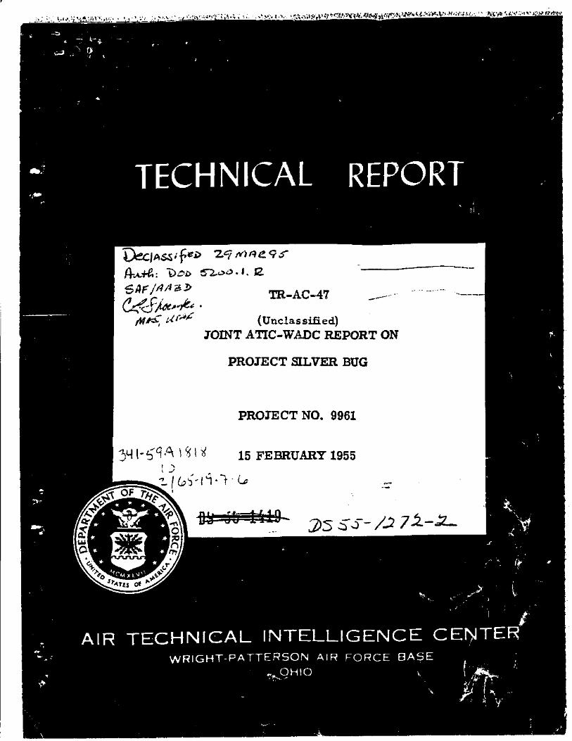
C. Performance
The performance estimated by the contractor was based on rather broad assumptions and has not as yet been investigated by a wind tunnel test program. (Gee Table III.)
17 T55-2CA9

i ro o
CD
123
r*»
«••»
Mraua
m C3
F i g . 12 Cross -Sec t ion Showing Bear ing Airflow

DIREaiON OF ROTATION
C. - • • • • • i - l * T —'-» - ',
ere
0 1
U3
TOP BEARING PLATE ROTOR
•-3 v/l
I IV) O
Fig . 13 Perspec t ive View Showing True Path of Bear ing Air

******
"- 22X THRUST
22% THRUST
99% THRUST
99% THRUST
F i g . 14 Exhaust Jet Angles at Low F o r w a r d Speed

ro
' ^
C " j
r«»
t o
rri C3
t-3
I ro o
Fig . 15 Coanda Effect: High Aspect Ratio Jet Bending
UNCLASSIFIED
TABUS I I I
CONTRACTOR ESTIMATED FSRFORMAIJCE
Radial -Flow 2ngine A i r c r a f t
P a r t i c u l a r s
Maximun l e v e l speed
C e i l i n g (l-Sax power a t sean st)
TIBK frora hover ing s t a r t t o 36,090 f t 6c ,000 f t 70,000 f t
C t i l l a i r range v i t h a l lowances f o r t a k e - o f f , c l i u b , c r u i s e , d e s c e n t , aad l a n d i n g
Take-of f and l a n d i n g d i s t a n c e s
i Jax hover ing a l t from t a k e - o f f
Max hover ing a l t a t oean v t , 2e ,000 lba
aph kno t s Mach No.
f t
min min • i n
Dalles
f t
f t
Without Reheat
1,720 1,490
2 . 6
71,600
1.76 2 .66 k.2
620
N i l
10,000
18,000
V/ith 1500 °X Reheat
2,300 2,000
60,600
HA HA 3A
M l
IIA
HA
liOTS: The above es t imate u t i l i s e s net thruat3 and MC which are based on the "s inpl i -fying aasejaption" - "Plain nozzles and 100 per cent t h r u s t recovery fron the Jet bending."
T55-2cU9 22
UNCLASSIFIED