Vibration and Medium Weight Shock Test Report on 1.25” x 1 ...
Upload
duongquynhCategory
view
218download
0
1
Athena II Reliability & Environment Test Plan
Product Code:E062
BIOS Version:V2.0
APPROVED CHECK PREPARED
BY Al K. Alex L. Perry H. DATE 2008/03/25 2008/03/24 2008/03/21
2
Diamond Systems Corp. 1255 Terra Bella Ave. Mountain View, CA 94043
1. Vibration Test
1.1 Objective 1 Operating (Random Mode) The purpose of the vibration test is to determine mechanical weakness or performance degradation of an equipment or component when subjected to vibration and to use this information, in conjunction with the relevant specifications, to decide whether the equipment or component, herein after referred to as DUT, is acceptable or not. It may be used in some cases to determine the structural integrity of the DUT and study its dynamic behavior. 2 Operating (Sine Mode) The purpose of the transport vibration test is to determine the protective ability of packaging materials which cushion, enclose and protect the finished products to withstand transportation stresses during shipment and handling.
1.2 Test Procedure 1. Inspect the DUT to establish operation pretest criteria and physical condition. 2. Verify the functionality of the DUT. 3. Mount the velocity transducers of the accelerometer on the surface of the DUT main components (usually choose the HDD) and take a picture. Repeat steps 1~2. 4. Mount the DUT on the vibration equipment table. 5. Expose the DUT to the test level and duration as determined from the Specifications. 6. Inspect the DUT and compare it to pretest data and physical condition, if anything physical issue or malfunction during testing should under recorded & reported. 7. Repeat steps 1~6 for each axis.
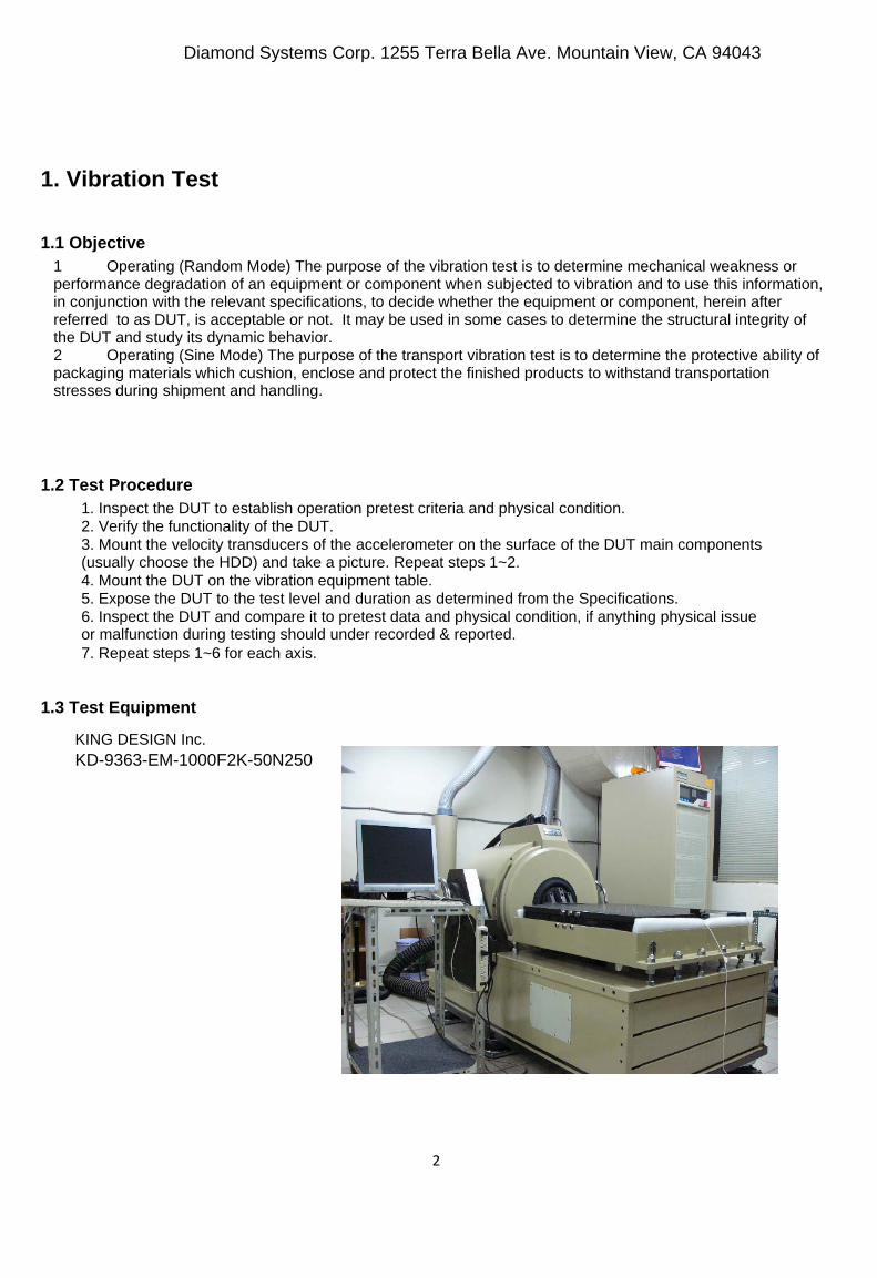
1.3 Test Equipment
KING DESIGN Inc. KD-9363-EM-1000F2K-50N250
3
Diamond Systems Corp. 1255 Terra Bella Ave. Mountain View, CA 94043
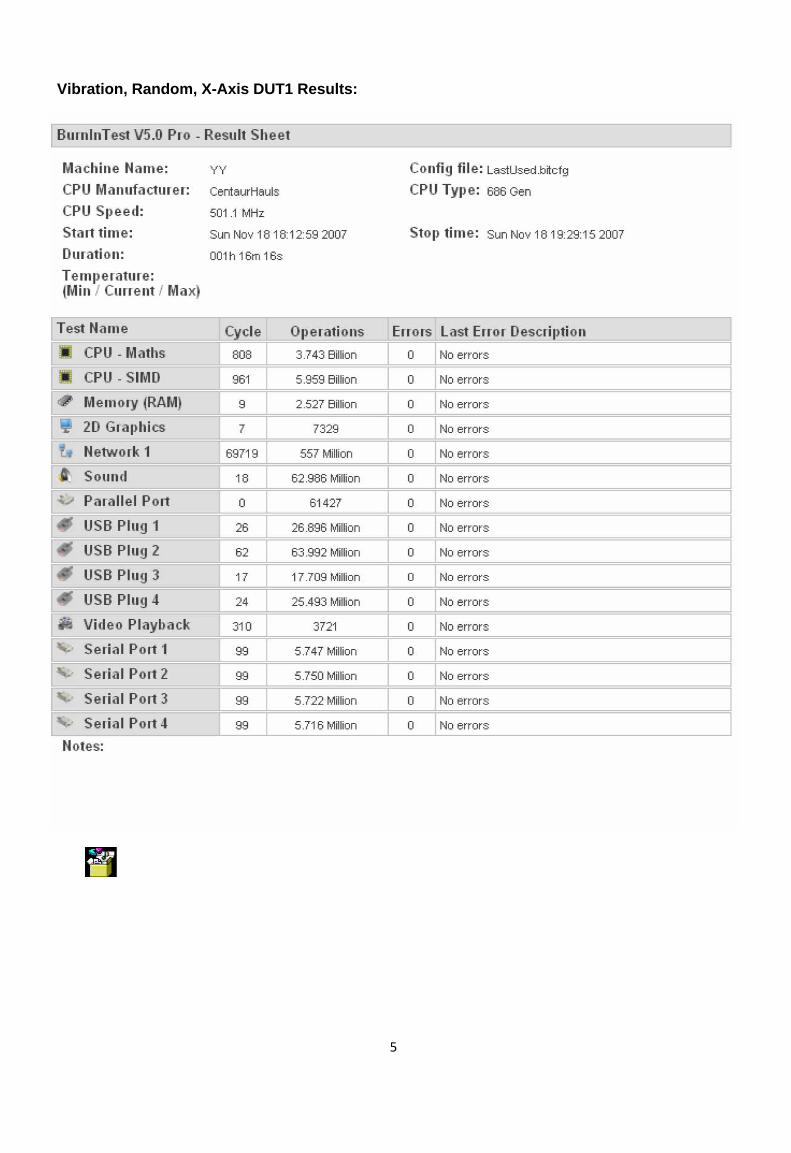
1.4 Test Software Passmark Burn-in Test Program V5.0 under Microsoft Windows XP SP2.
1.5 Test Location A Certified Reliability & Environment Lab (contract)
1.6 Test Specifications
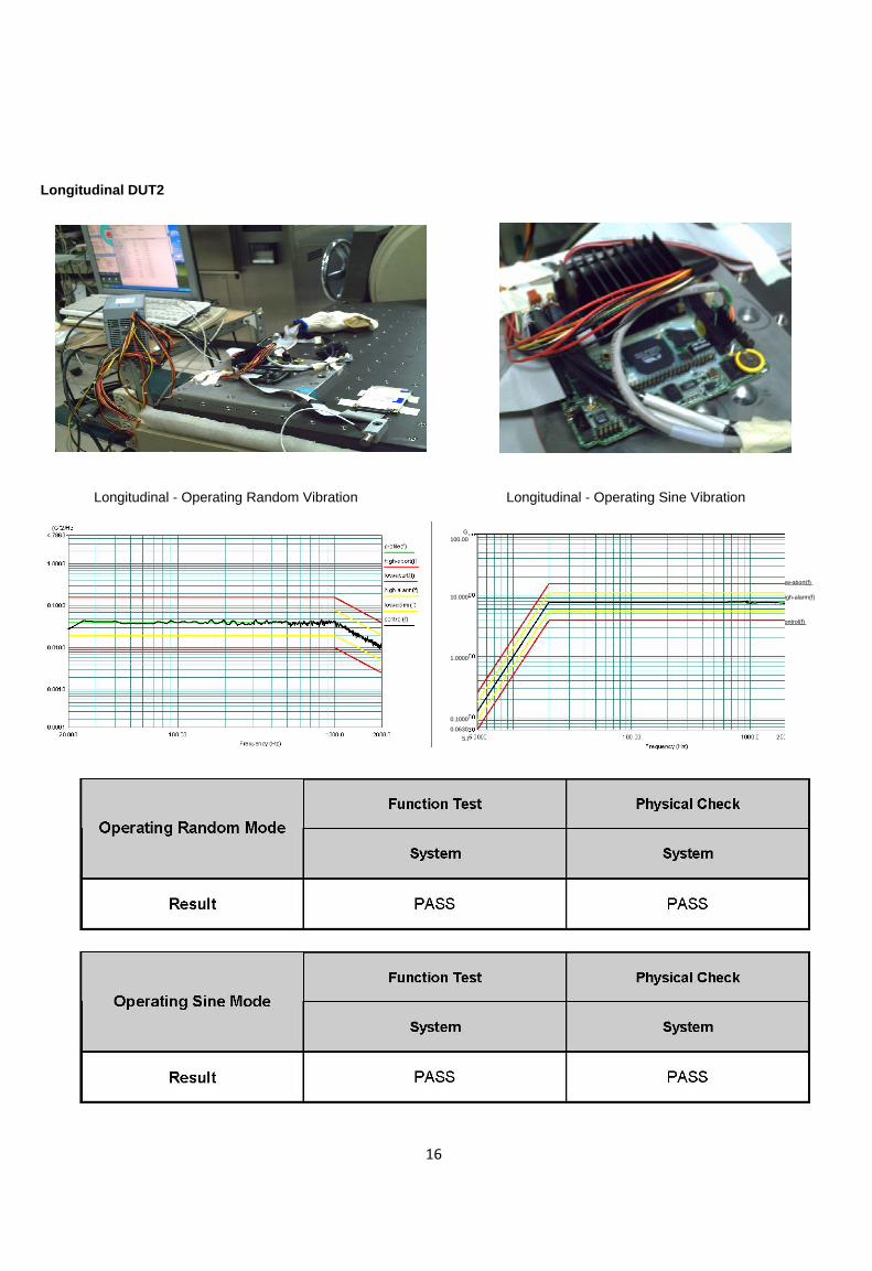
Operating Random Vibration Mode:Axes: Vertical / Transverse / Longitudinal. 7.7Grms 20-2000 Hz Random Vibration. 60min/axis.
Operating Swept Sine Mode: Axes: Vertical / Transverse / Longitudinal. 0.01in. p-p, 5-20Hz, 7.7g peak, 20-2000Hz Swept Sine, 60min/axis.
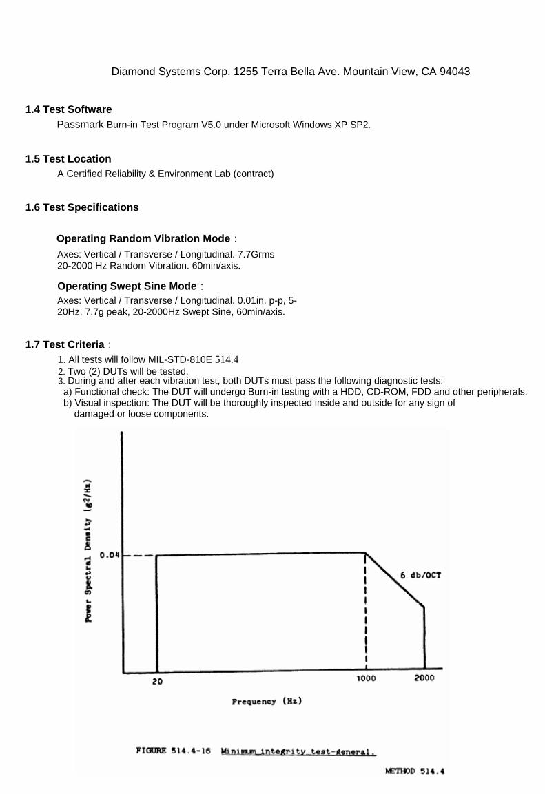
1.7 Test Criteria: 1. All tests will follow MIL-STD-810E 514.4 2. Two (2) DUTs will be tested. 3. During and after each vibration test, both DUTs must pass the following diagnostic tests: a) Functional check: The DUT will undergo Burn-in testing with a HDD, CD-ROM, FDD and other peripherals. b) Visual inspection: The DUT will be thoroughly inspected inside and outside for any sign of damaged or loose components.

4
1.8 Test Result
Transverse DUT1
Transverse- Operating Random Vibration Transverse- Operating Sine Vibration
5
Vibration, Random, X-Axis DUT1 Results:

6
Vibration, Sine, X-Axis DUT1 Results:

7
Longitudinal Random Vibration Results:

8
Vibration, Random, Y-Axis DUT1 Results:

9
Vibration, Sine, Y-Axis DUT1 Results:

10
Vertical DUT1
Vertical - Operating Random Vibration Vertical - Operating Sine Vibration

11
Vibration, Random, Z-Axis DUT1 Results:
PAGE 11 Ver. 1.02

12
Vibration, Sine, Z-Axis DUT1 Results:
PAGE 12 Ver. 1.02

13
Transverse DUT2
Transverse- Operating Random Vibration Transverse- Operating Sine Vibration

14
Vibration, Random, X-Axis DUT2 Results:
PAGE 14 Ver. 1.02

15
Vibration, Sine, X-Axis DUT2 Results:
PAGE 15 Ver. 1.02
16
Longitudinal DUT2
Longitudinal - Operating Random Vibration Longitudinal - Operating Sine Vibration
G 100.00 profile(f) high-abort(f)
low-abort(f)
high-alarm(f)10.000 low-alarm(f)
control(f)
1.0000
0.1000
0.0630 2000.0 5.0000 100.00 1000.0 Frequency (Hz)

17
Vibration, Random, Y-Axis DUT2 Results:
PAGE 17 Ver. 1.02

18
Vibration, Sine, Y-Axis DUT2 Results:
PAGE 18 Ver. 1.02

19
Vertical (Z-Axis) DUT2 Setup:
Vertical - Operating Random Vibration Vertical - Operating Sine Vibration

20
Vibration, Random, Z-Axis DUT2 Results:
PAGE 20 Ver. 1.02

21
Vibration, Sine, Z-Axis DUT2 Results:
PAGE 21 Ver. 1.02

22
2. Shock Test
2.1 Objective The shock test is performed to ensure that material can withstand the relatively infrequent, non-repetitive shocks or transient vibration encountered in handling, transportation and service environments.
2.2 Test Procedure 1. During 6 faces, 3 shocks per axis: each DUT is required to withstand the 6 shocks in order to pass the Half-Sine Wave shock test. 2. The DUT will be installed on shock table in such a way that the shock input is transmitted directly to it. The DUT will be fixture using a predetermined torque value, 3. Place accelerometers on the shock-sensitive components (i.e. HDD, RAM…) in order to measure the response acceleration.
2.3 Test Equipment
KING DESIGN Inc.
KD-9363-EM-1000F2K-50N250
PAGE 22 Ver. 1.02

23
2.4 Test Software Passmark Burn-in Test Program V5.0 under Microsoft Windows XP SP2.
2.5 Test Location A Certified Reliability & Environment Lab.
2.6 Test Specifications
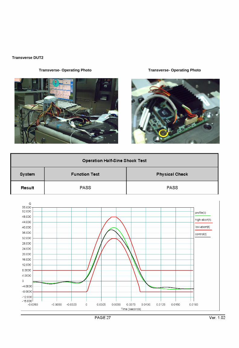
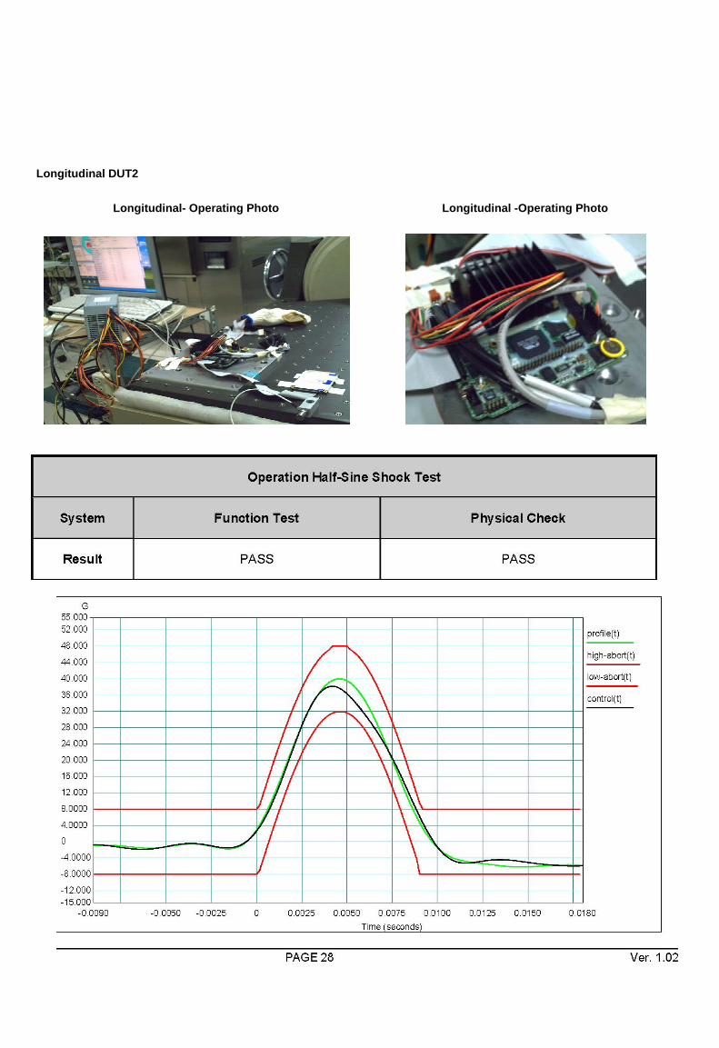
Reference IEC68-2-27 Testing Procedures 1. Operating Shock Half-Sine Wave Shock 40 G: 9ms: 18 shocks per
axis: Vertical / Transverse / Longitudinal.
2.7 Test Criteria 1. A minimum of 1 DUT must be tested. 2. After non operation half-sine wave shock test, all DUT must pass the Burn-in test without any functional and mechanical malfunction. 3. Diagnostics: a) Functional check: The DUT will under go Burn-in testing the HDD, CD-ROM, FDD and main board.
b) Visual inspection: The DUT will be thoroughly inspected inside and outside for any sign of damage, looseness or loose of components.

24
2.8 Test Results
Transverse DUT1
Transverse Shock DUT1 Setup Close-Up

25
Longitudinal DUT1
Longitudinal- Operating Photo Longitudinal -Operating Photo

26
Vertical DUT1
Vertical- Operating Photo Vertical-Operating Photo
27
Transverse DUT2
Transverse- Operating Photo Transverse- Operating Photo
28
Longitudinal DUT2
Longitudinal- Operating Photo Longitudinal -Operating Photo

29
Vertical DUT2
Vertical- Operating Photo Vertical-Operating Photo
30
3. Drop Test
3.1 Objective The ones that assessed the products and used movements to produce because of the improper one fell; and the strong toughness under the safety condition that the necessary products are assessed.
3.2 Test Procedure 1.Turn on the DUT to perform function test, then turn off the DUT, package the DUT and place it on the drop tester. 2.To perform corner drops according to Figure 9-1 (C1~C4) on the weakest corner of DUT. 3.To perform flat drops according to Figure 9-1(S1~S6) with impact on the flats. 4.To perform edge drops according to Figure 9-1 (E1~E3) with impact on the edges. 5.To inspect the packaged DUT mechanical structure, and to execute the function test.
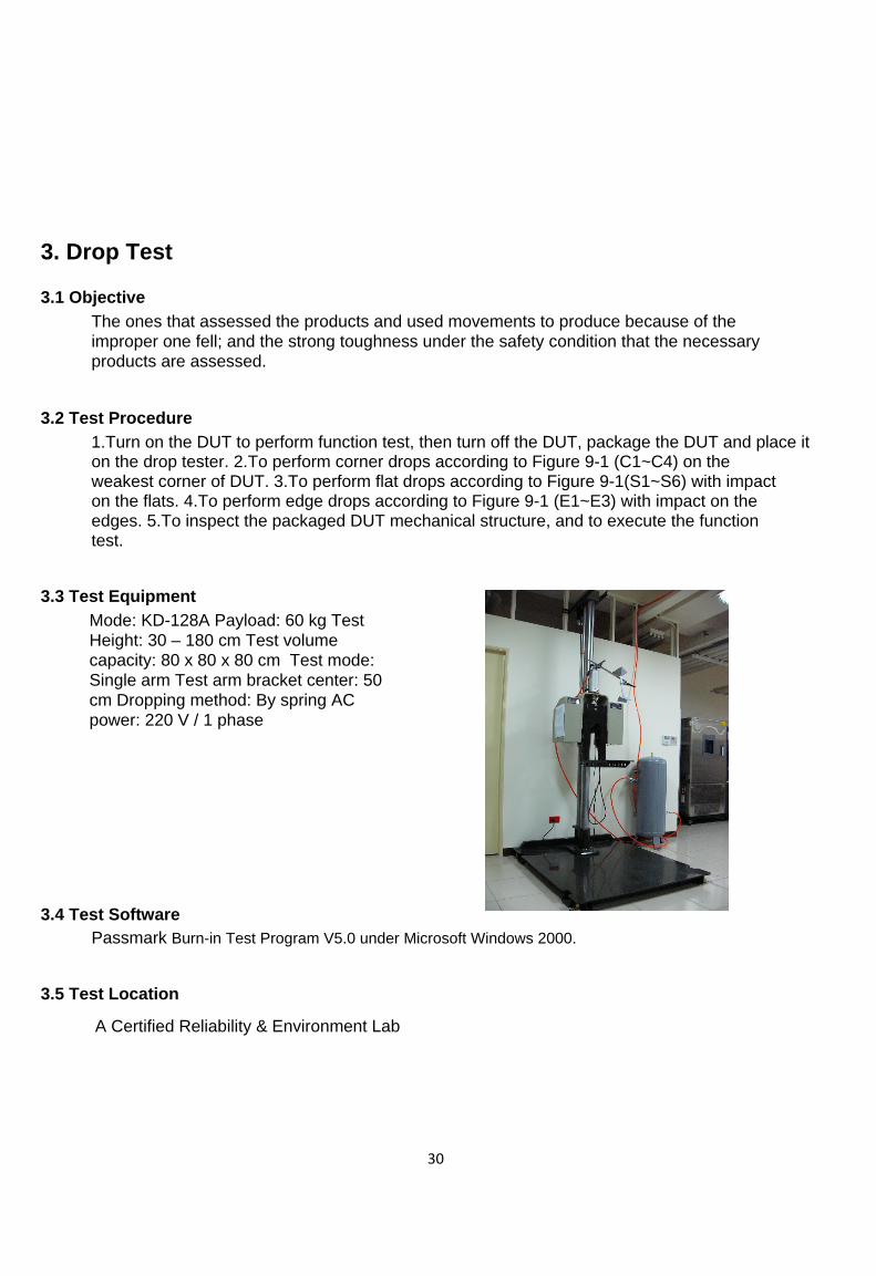
3.3 Test Equipment Mode: KD-128A Payload: 60 kg Test Height: 30 – 180 cm Test volume capacity: 80 x 80 x 80 cm Test mode: Single arm Test arm bracket center: 50 cm Dropping method: By spring AC power: 220 V / 1 phase
3.4 Test Software
Passmark Burn-in Test Program V5.0 under Microsoft Windows 2000.
3.5 Test Location
A Certified Reliability & Environment Lab

31
3.6 Test Specification Reference ISTA (International Safe Transit Association) 2A 2001 Testing Procedures
S5 C4 S2
Package Weight Drop Height Impact Velocity
kg lb mm inch
ft/s m/s
0 ~ 9.55 0 ~ 21 965 38 14.3 4.4
9.55 ~ 18.64 21 ~ 41 813 32 13.1 4.0
18.64 ~ 27.73 41 ~ 61 660 26 11.8 3.6
27.73 ~ 45.45 61 ~ 100 508 20 10.4 3.2
45.45 ~ 68.2 100 ~ 150 305 12 8.0 2.5
> 68.2 > 150 152 6 5.7 1.7
13 Drops: 4 corner,3 edges and 6 surfaces

32
Figure 9-1
3.7 Test Criteria
1. A minimum of 1 DUT must be tested. 2. The minimum DUT testing is based on covering the multi sourcing of key components that can present weakness regarding mechanical stress: Power supply, Heat sink, Fans, HDD, CD-ROM, or add-on cards.
3. During and after the drop test, all DUTs must pass the following diagnostic tests:
a) Functional check: The DUT will under go Burn-in test applications testing the HDD, CD-ROM, FDD and main board.
b) Visual inspection: The DUT must be without any mechanical damage. Package inside cushion materials rupture is permitted.
3.8 Test Results:
.. . . . . .............
Condition 4 corners
Drop High 96.5 Cm
Functional System PASS
Physical System PASS
Remark -
3 edges 96.5 Cm PASS PASS -
6 surfaces 96.5 Cm PASS PASS -