ATERPILLAR 3056E ENGINE YDROSTATIC RIVE
86
Model Year 2005 ROGATOR 418 CATERPILLAR 3056E ENGINE - HYDROSTATIC DRIVE OPERATOR' S MANUAL P/N 611871-A
Transcript of ATERPILLAR 3056E ENGINE YDROSTATIC RIVE

Model Year 2005
ROGATOR 418 CATERPILLAR 3056E ENGINE - HYDROSTATIC DRIVE
OPERATOR'S MANUAL
P/N 611871-A

FOREWORD
i
RoGator 418
Safety is Your Responsibility READ AND UNDERSTAND THIS MANUAL BEFORE OPERATING THIS VEHICLE OR ANY OF ITS CONNECTED SYSTEMS. THIS ALSO APPLIES FOR ALL FURTHER MANUALS DELIVERED WITH THIS VEHICLE. Please contact your Ag-Chem Europe BV Service Centre if the information contained in this manual is not complete or partially incomprehensible or if you have any questions. Ag-Chem Europe BV cares about safety. This vehicle and its connected systems are designed to provide the maximum possible safety. However, no machine design can prevent operator error or care-lessness. This operator's manual provides instructions for the safe operation of this vehicle. Make sure that the vehicle, connected systems and components are in a good condition. Check the Maintenance Schedule in this manual before operation. Definition of safety symbols and instructions: All safety instructions are preceded by the warning symbol. Carefully read and follow the instructions beside the symbols:
DANGER!
An extreme inherent hazard ex-ists which could result in injury or death if proper precautions are not taken.
WARNING!
A hazard exists which could re-sult in injury or death if proper precautions are not taken.
CAUTION!
A reminder of safety practices or attention to unsafe practices which could result in injury or death if proper precautions are not taken.
IMPORTANT: Important instructions to prevent damage to the vehicle , systems and components. This also identifies in-formation worthy of special attention. NOTE: General information about the correct operation and maintenance of the vehicle, systems and components. Notice: Information, illustrations and specifications in this manual are based on the latest informa-tion available at the time of publication. All rights are reserved to make changes at any time without notice. Some illustrations may show optional equip-ment. Illustrations may show shields, guards, etc. open or removed for illustration purposes only. All shields, guards, etc. must be in place during operation of this vehicle and systems.
Copyright © 2005 Ag-Chem Europe BV
Horsterweg 66a 5971 NG Grubbenvorst
Netherlands Tel. (0031)-77-3278400
ii
WARNING Please note the following: • Always start and operate the engine in a
well-ventilated area. • Never operate the vehicle’s engine inside a
building unless adequate ventilation is pro-vided to safely and properly remove the exhaust fumes.
• NEVER modify or tamper with the exhaust
system in any way.
If there are any questions about this manual, don’t take any risks. Please contact Ag-Chem Europe BV.

TABLE OF CONTENTS
I
RoGator 418
SAFETY............................................................01 Follow Safety Instructions...........................................01.1 Preparation for Emergencies .....................................01.1 Emergency Exit from Cabin.........................................01.1 Safe Operation of the Vehicle .....................................01.2 Prevent Vehicle Runaway............................................01.2 Use of Safety Lights and Safety Devices..................01.3 Operating on Slopes.....................................................01.3 Travelling on Public Roads ..........................................01.3 Stopping and Parking the Vehicle ..............................01.4 System Boom Safety ....................................................01.4 Avoid Eye Contact with Radar .....................................01.4 Exhaust Gases ...............................................................01.4 Overhead Electrical Power Lines...............................01.5 Noise ................................................................................01.5 Safe Handling of Fuel - Avoid Fires ............................01.5 Stay Clear of Rotating Power Takeoffs and Moving Parts ..................................................................01.6 Towing Other Vehicles ................................................01.6 Modifications..................................................................01.6 Safety Treads and Grips ..............................................01.6 Chemical Safety.............................................................01.7 Maintenance and Service Safety ................................01.8 Practice Safe Maintenance ..........................................01.8 Wear Protective Clothing.............................................01.8 Clean Working Area......................................................01.9 Proper Servicing................................ ............................01.9 Use of Proper Tools ......................................................01.9 Proper Support of Vehicle ...........................................01.9 Proper Lifting Equipment ............................................01.9 High-Pressure Fluids ..................................................01.10 Hydraulic Hoses...........................................................01.10 Avoid Great Heat Near Pressurized Fluid Lines....01.10 Safe Servicing of Cooling System............................01.10 Removal of Paint before Welding or Heating .........01.11 Batteries........................................................................01.11 Tyres and Wheels .......................................................01.11 Dispose of Waste Properly........................................01.12 Mobile Radio Installations..........................................01.12 Location of Safety and Service Decals Chassis ....01.13 Location of Safety and Service Decals Cabin.........01.15
INTRODUCTION................................................02 Before Operating the RoGator 418.............................02.1 Identification...................................................................02.2
Serial Number Identification Plates..............................02.2 Engine Serial Number..................................................02.2
Hydrostatic Drive ...........................................................02.3 Traction Control Lever, Pump and Wheel Motors.......02.3 Engine.........................................................................02.3 Low -pressure Pump...................................................02.3 Cooler .........................................................................02.3 Tank and Filter................................ ............................02.3
Break -in Period..............................................................02.4 First 100 Hours of Operation......................................02.4 Hydraulic System........................................................02.4 Engine Coolant Level..................................................02.4 Wheel Mounting Bolts ................................ .................02.4 Maintenance Schedule ...............................................02.4
Chassis and Cab Modifications ..................................02.4 Towing.............................................................................02.4
Towing with Engine Operable ....................................02.4
Towing with Engine Disabled .....................................02.4 RoGator towing Procedure ........................................02.5
Transport........................................................................02.5 Mobile Radio...................................................................02.5 Location of Components.............................................02.6
CONTROLS ................................ ......................03 Operation........................................................................03.1
Turn Signal, Lights and Horn Lever............................03.1 Adjustment of the steering wheel..............................03.1
Accelerator Pedal..........................................................03.1 Traction Control Lever................................ .................03.2
Positions of the Traction Control Lever......................03.2 (1) Neutral.............................................................03.2 (2) Driving Forwards.............................................03.2 Field Position..........................................................03.2 Road Position.........................................................03.2 (3) Reversing ........................................................03.2 Field Position..........................................................03.2 Road Position.........................................................03.2
Adjustment of the Traction Control Lever Position .....03.3 Brakes (Option) .............................................................03.4
Brake/Inching Pedal....................................................03.4 Parking Brake.............................................................03.4
Turning the Controller On and Off.............................03.4 Engine Speed Governing.............................................03.4
Engine RPM On/Off switch.........................................03.4 Engine RPM switch.....................................................03.4 From inside the cab....................................................03.4 From the remote switch box ................................ ......03.4
Instrument Panel ..........................................................03.5 Ignition Switch...............................................................03.6 Suspension ....................................................................03.6
Automatic suspension switch....................................03.6 Manual suspension switch........................................03.6
Driving in the Field or on the Road.............................03.6 4-Wheel steering...........................................................03.6
4-Wheel steering switch............................................03.6 4-Wheel steering foot switch.....................................03.6
Switching the spray computer On/Off ......................03.7 Remote Throttle Control .............................................03.7
Electronic Governing On / Off Switch........................03.7 Engine speed switch..................................................03.7 Spraypump On / Off ...................................................03.7 Res 1 / Res 2..............................................................03.7
Control Buttons on Traction Control Lever .............03.7 Master Switch............................................................03.7 Fast Speed Range Switch.........................................03.7 Slow Speed Range Switch........................................03.7
Lighting and door handling of the cab......................03.8 Door Latch..................................................................03.8 Sun Visor ...................................................................03.8 Cabin light switch.......................................................03.8
Seat..................................................................................03.9 Location of seat controls ...........................................03.9
1 Weight adjustment..............................................03.9 2 Height adjustment ...............................................03.9 3 Fore / aft isolator ................................................03.9 4 Fore / aft adjustment ..........................................03.9 5 Seat pan angle adjustment.................................03.9 6 Seat depth adjustment........................................03.9 7 Backrest extension ............................................03.9 8 Lumbar support..................................................03.9
TABLE OF CONTENTS
II
RoGator 418
9 Armrest...............................................................03.9 10 Armrest adjustment ..........................................03.9 11 Backrest adjustment.........................................03.9 12 Swivel...............................................................03.9 13 absorber ...........................................................03.9
External Lighting and Temperature Control Panel in the Cabin...................................................................03.10
Work Light Switch One.............................................03.10 Work Light Switch Two............................................03.10 Work Light Switch Three..........................................03.10 Work Light Switch Four............................................03.10 Hazard Warning Light Switch (Orange Flashing Warning Lights)............................03.10 Beacon Light Switch - Option...................................03.10 Stop lamp..................................................................03.10 Warning / cold start lamp ..........................................03.10 Automatic suspension switch..................................03.10 Manual suspension switch.......................................03.10 Temperature Control Knob........................................03.10 Air Conditioner / Heater Switch................................03.10 Blower Speed Switch ..............................................03.10
INSTRUMENT PANEL........................................04 Instrument panel dashboard......................................04.1
Speedometer ..............................................................04.2 Fuel level gauge..........................................................04.2 Battery voltage gauge ................................................04.2 High beam ON indicator light.......................................04.2 Parking brake warning light........................................04.2 Left turn signal light ....................................................04.2 Right turn signal light...................................................04.2 Suction / return line filter and leak oil filter indicator light...............................................................04.2 Boost pressure indicator light.....................................04.2 Hydraulic oil level indicator light..................................04.2 Oil temperature indicator light .....................................04.2 Transmission neutral indicator light............................04.2 Transmission in first gear indicator light.....................04.2 Transmission in second gear indicator light ...............04.2 Transmission in third gear indicator light ....................04.2 All-steer mode indicator light ......................................04.2 Two-wheel-steer mode indicator light........................04.2 Front axle in middle position indicator light..................04.2 Rear axle in middle position indicator light..................04.2 Reset button speedometer .........................................04.2
General description GEM .............................................04.3 Getting started...............................................................04.3 General ............................................................................04.4
Setting display contrast and lighting ...........................04.4 Using the soft keys.....................................................04.4 The main engine display .............................................04.4 Engine hours...............................................................04.4 Trip engine hours........................................................04.4 The quad display ........................................................04.5 The graph display .......................................................04.6 The quad and graph parameters................................04.6 The alarm display screen ...........................................04.7 Pop-up messages and warnings ...............................04.7
Configuration .................................................................04.8
OPERATION .....................................................05 Before Starting the Vehicle Engine............................05.1
Starting the Engine .......................................................05.2 Restarting a Stalled Engine.........................................05.2 Starting at Low Temperatures ...................................05.2
Hydraulic System – Operation at Low Temperatures05.2 Driving the RoGator.......................................................05.3
Driving the RoGator with the “Field / Road” Switch in the “Road” Position................................ .................05.3 Driving the RoGator with the “Field / Road” Switch in the “Field” Position..................................................05.3 Economic Driving........................................................05.3 Speed Ranges:...........................................................05.3
4-Wheel Steering...........................................................05.4 Operation....................................................................05.4 Switch for 4-Wheel Steering................................ ......05.4 Automatic ...................................................................05.4 Manual........................................................................05.4 4-Wheel Steering Off................................ .................05.4 Driving on Public Roads..............................................05.4 Turning Machine Off with Rear Wheels Steered.......05.4
Front Axle Suspension ( Option )...............................05.5 Automatic Position......................................................05.5 Manual Position...........................................................05.5
Hydraulic Skid Regulator (option) .............................05.5 Switching the skid regulator On/Off ...........................05.5
Automatic Adjustment of the Track Width ( Option )05.6 Sliding the Axle...........................................................05.6 Setting the Track Width ..............................................05.6 Track width 1,50 - 2,00 m (Front axle).......................05.7 Track width 1,80 - 2,25 m (Front axle).......................05.7 Track width 2,00 - 2,25 m (Front axle).......................05.8 Maintenance of the sliding axle..................................05.8
Separ ate Ladder............................................................05.9 Motor Platform............................................................05.9
Diesel filling point .........................................................05.9 Remote Throttle Control .............................................05.9
Electronic Gpverning On / Off Switch........................05.9 Engine Speed Switch................................ .................05.9 Spraypump On / Off...................................................05.9 Res 1/ Res 2...............................................................05.9
Travelling on Public Roads ..........................................05.9
MAINTENANCE.................................................06 Maintenance Introduction ...........................................06.1 Lubricants and Fluids...................................................06.1
Lubricant Filling Reminders.........................................06.1 Maintenance Symbols..................................................06.2 Maintenance Schedule................................ .................06.3 Compressed Air System Maintenance ....................06.5
Compressed Air System............................................06.5 Air Conditioner ..............................................................06.5 Engine ..............................................................................06.5
Checking the Oil Level ................................................06.5 Changing the Engine Oil and Oil Filter.........................06.5 Engine Belts................................................................06.6 Engine Coolant............................................................06.6 Supplemental Coolant Additives (SCA’s) ..................06.6
Air Cleaner Maintenance .............................................06.7 Primary Filter Element................................ .................06.7 Inner Filter Element .....................................................06.8
Fuel..................................................................................06.8 Fuel Tank ....................................................................06.8 Fuel Storage...............................................................06.8 Fuel Filter....................................................................06.8

TABLE OF CONTENTS
III
RoGator 418
Replace the Fuel Filter ...........................................06.8 Priming of the Fuel System ....................................06.9
Tyre Maintenance ........................................................06.10 Tyre Mounting...........................................................06.10 Tyre Pressure Chart.................................................06.11
Wheel Maintenance.....................................................06.11 Removing the Wheels................................ ...............06.11 Installing the Wheels .................................................06.11
Cab Air filter .................................................................06.12 Anti carbide filter ......................................................06.12
Cab Mounting Bolts .....................................................06.12 Windshield Wiper Blade .............................................06.12 Windshield Washer Reservoir ..................................06.12 Hydraulic (Hydrostatic) System ................................06.13
Replacing Hydraulic Fluid and Filters in Hydraulic System..................................................06.13
Replacing the Suction and Return Line Filter.......06.13 Replacing the Leakage Oil Filter...........................06.13
Heat Exchanger ............................................................06.14 Electrical System.........................................................06.14
Electrical System Safety...........................................06.14 Batteries ...................................................................06.14 Fuse Panel................................................................06.15
Jump Starting...............................................................06.16 Storage of Vehicle .......................................................06.16
Before Operating the Vehicle after a Long Storage.06.16 Cab Seat Preventative Maintenance ........................06.17
Lubricate Adjusters Twice a Year...........................06.17 Armrest Mechanism..................................................06.17
Paint and Decals...........................................................06.17 Safety Treads ...............................................................06.17 Maintenance Parts RG618 ..........................................06.17
COLD WEATHER OPERATION ..........................07 Minimising the effect of cold weather......................07.1
Seasonal viscosity Oil and Proper coolant concentration................................ .................07.1 Idling the engine ..........................................................07.1 Engine coolant specification.......................................07.1 Water quality...............................................................07.1 Ethylene glycol concentrate.......................................07.1 Supplement coolant additives (SCA's) .......................07.1 Diesel Engine Oil recommendations............................07.2 Mixing of lubricants.....................................................07.2 Grease........................................................................07.2 Diesel fuel...................................................................07.3 Diesel fuel storage......................................................07.3
LONG TERM STORAGE ....................................08 Long Term Storage Preparation ................................08.1 Long Term Storage Removal ......................................08.1
TROUBLESHOOTING........................................09 Engine ................................................................................9.1 Electrical System.............................................................9.2 Hydraulic System.............................................................9.3 Brakes ...............................................................................9.3 Steering.............................................................................9.3 Cabin ..................................................................................9.4
SPECIFIACTIONS .............................................10 Chassis Specifications ................................................10.1
Engine.........................................................................10.1 Traction Pump.............................................................10.1 Wheel Motors.............................................................10.1 Service Brake (Option)...............................................10.1 Parking Brake.............................................................10.1 Steering................................ ................................ ......10.1 Frame .........................................................................10.1 Air Cleaner .................................................................10.1 Exhaust ................................ ................................ ......10.1 Fuel Tank ....................................................................10.1 Electrical System........................................................10.1 Hydraulic System.......................................................10.1 Compressed Air System............................................10.1 Cab.............................................................................10.1 Turning Radius ...........................................................10.1 Tyres ..........................................................................10.1 Ground Clearnance....................................................10.1 Speed Ranges............................................................10.1 Options.......................................................................10.2 Chassis Weights ........................................................10.2 Dimensions .................................................................10.2
INDEX......................................................... INDEX

SAFETY
01.1 Safety 11-04
RoGator 418
IMPORTANT: Tampering with the engine is against the law. Any modifications on the vehicle or its sys-tems not authorised by Ag-Chem Europe BV can cre-ate a safety hazard and void the warranty. This also includes self-repair of malfunctions.
Follow Safety Instructions Never operate the vehicle and/or equipment without proper instruction and/or a complete understanding of control operation! Carefully read, learn and understand all safety messages and information in this manual and on the vehicle’s safety signs. Keep safety signs in good condition. Replace miss-ing or damaged safety signs. Make sure new equipment components and repair parts include the current safety signs. Replacement safety signs are available from your Ag-Chem Europe BV. Learn how to operate the vehicle and how to use all con-trols properly BEFORE OPERATION. Do not let anyone operate the vehicle, systems or perform service and maintenance procedures without the proper instruction. Keep the vehicle, all components and systems in the proper working condition. Modifications unauthorized by Ag-Chem Europe BV to the vehicle may impair the func-tion and/or safety, affects vehicle life, and can void the vehicle warranty.
Preparation for Emergencies Be prepared if a fire starts. Keep a first aid kit and fire extinguisher handy. In cases of emergency dial 112 or your own national emergency number. Keep emergency numbers for doctors, ambulance ser-vice, hospital and fire department readily available at all times.
Emergency Exit from Cabin Familiarise yourself with the use of the emergency exit at the right-hand side of the cab before operating the vehicle. Pull the green tab at the rear right-hand cab window to remove the glass seal. Push the right-hand window out and exit the vehicle through this opening.
SAFETY
01.2 Safety 11-04
RoGator 418
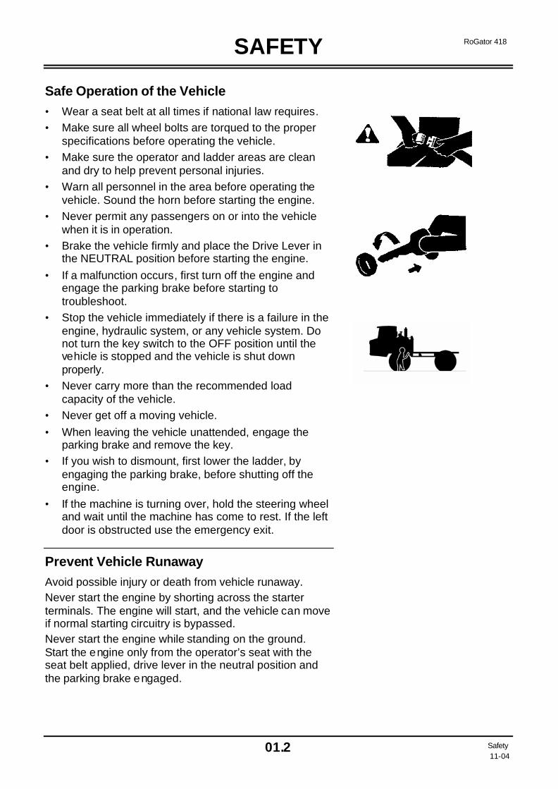
Safe Operation of the Vehicle • Wear a seat belt at all times if national law requires. • Make sure all wheel bolts are torqued to the proper
specifications before operating the vehicle. • Make sure the operator and ladder areas are clean
and dry to help prevent personal injuries. • Warn all personnel in the area before operating the
vehicle. Sound the horn before starting the engine. • Never permit any passengers on or into the vehicle
when it is in operation. • Brake the vehicle firmly and place the Drive Lever in
the NEUTRAL position before starting the engine. • If a malfunction occurs, first turn off the engine and
engage the parking brake before starting to troubleshoot.
• Stop the vehicle immediately if there is a failure in the engine, hydraulic system, or any vehicle system. Do not turn the key switch to the OFF position until the vehicle is stopped and the vehicle is shut down properly.
• Never carry more than the recommended load capacity of the vehicle.
• Never get off a moving vehicle. • When leaving the vehicle unattended, engage the
parking brake and remove the key. • If you wish to dismount, first lower the ladder, by
engaging the parking brake, before shutting off the engine.
• If the machine is turning over, hold the steering wheel and wait until the machine has come to rest. If the left door is obstructed use the emergency exit.
Prevent Vehicle Runaway Avoid possible injury or death from vehicle runaway. Never start the engine by shorting across the starter terminals. The engine will start, and the vehicle can move if normal starting circuitry is bypassed. Never start the engine while standing on the ground. Start the engine only from the operator’s seat with the seat belt applied, drive lever in the neutral position and the parking brake engaged.
SAFETY
01.3 Safety 11-04
RoGator 418
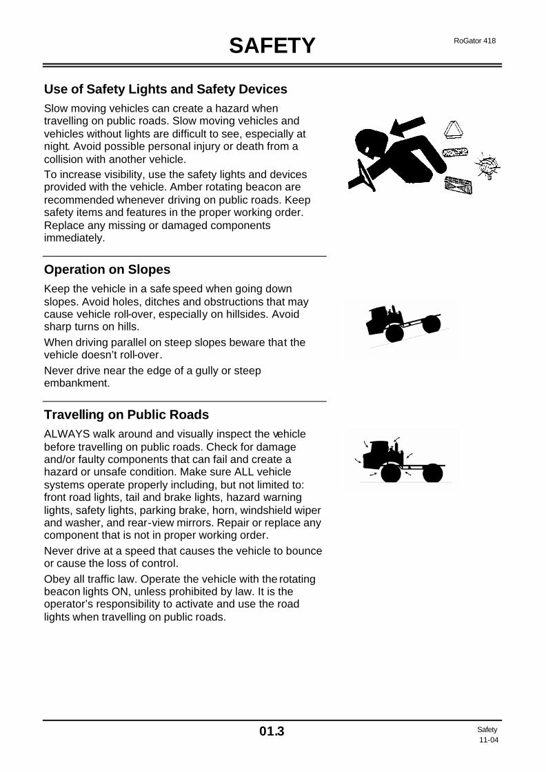
Use of Safety Lights and Safety Devices Slow moving vehicles can create a hazard when travelling on public roads. Slow moving vehicles and vehicles without lights are difficult to see, especially at night. Avoid possible personal injury or death from a collision with another vehicle. To increase visibility, use the safety lights and devices provided with the vehicle. Amber rotating beacon are recommended whenever driving on public roads. Keep safety items and features in the proper working order. Replace any missing or damaged components immediately.
Operation on Slopes Keep the vehicle in a safe speed when going down slopes. Avoid holes, ditches and obstructions that may cause vehicle roll-over, especially on hillsides. Avoid sharp turns on hills. When driving parallel on steep slopes beware that the vehicle doesn’t roll-over. Never drive near the edge of a gully or steep embankment.
Travelling on Public Roads ALWAYS walk around and visually inspect the vehicle before travelling on public roads. Check for damage and/or faulty components that can fail and create a hazard or unsafe condition. Make sure ALL vehicle systems operate properly including, but not limited to: front road lights, tail and brake lights, hazard warning lights, safety lights, parking brake, horn, windshield wiper and washer, and rear-view mirrors. Repair or replace any component that is not in proper working order. Never drive at a speed that causes the vehicle to bounce or cause the loss of control. Obey all traffic law. Operate the vehicle with the rotating beacon lights ON, unless prohibited by law. It is the operator’s responsibility to activate and use the road lights when travelling on public roads.
SAFETY
01.4 Safety 11-04
RoGator 418
Stopping and Parking the Vehicle Vehicle roll-over, collisions, runaway vehicles, and people being crushed under vehicles can occur when the vehicle’s operator ignores operation safety procedures. Signal before stopping, turning or slowing down on public roads, or anywhere it will cause a potential safety hazard. Pull over to the side of the road before stopping the vehicle. Be extremely careful when stopping the vehicle on slippery surfaces. Be extremely careful when towing or stopping with heavy loads. Always engage the Parking Brake when the vehicle is stopped. Remove the key to prevent any unauthorized personnel from operating the vehicle.
System Boom Safety If you have a system with booms, make sure no personnel or objects are ever in the path of the booms before operating them, especially when folding or unfolding them. Be aware of the location of the booms at all times. Before driving on public roads fold and lock the booms in transport position.
Avoid Eye Contact with Radar Radar ground sensors emit a low intensity microwave signal. The microwave signal will not cause any ill effects during normal use. Although the intensity is low, to avoid eye damage, never look directly into the sensor while the sensor is in operation.
Exhaust Fumes Always work in a properly ventilated area. Engine exhaust fumes can cause sickness or death. If it is necessary to run an engine in an enclosed area, use the proper equipment to safely remove the exhaust fumes from the working area. Always open the doors and get fresh outside air into the working area. Never operate the engine inside a building unless adequate ventilation is provided to safely and fully remove the exhaust fumes.

SAFETY
01.5 Safety 11-04
RoGator 418
Overhead Electric Power Lines Never let the vehicle come into contact with overhead power lines. The antenna’s must be turned over and se-cured in place any time overhead electrical power lines are near the vehicle. This can decrease the possibility that the vehicle may come into contact with an overhead power line when in operation or when the vehicle is transported.
Noise Long periods of exposure to high decibels or loud noise can cause hearing impairment or even loss of hearing. Wear proper hearing protection during periods of exposure to high decibels or loud noise.
Safe Handling of Fuel – Avoid Fires Handle fuel with care: it is highly flammable. Always stop the engine before refuelling the vehicle. Never refuel the vehicle while smoking. Add fuel in a safe place, away from open flame or sparks. Fill the fuel tank only outdoors. Never fill the fuel tank completely to the top of the fuel tank. Clean up any spilled fuel immediately. Never use diesel fuel, kerosene, gasoline or any flammable solvents for cleaning. NEVER use flammable solvents for cleaning anything. Prevent fire hazards by keeping the vehicle clean of any accumulated trash, grease and debris. Always have a multipurpose dry chemical fire extinguisher filled and available during vehicle operation and adding fuel. Know how to use it.
SAFETY
01.6 Safety 11-04
RoGator 418
Stay Clear of Rotating Power Takeoffs and Moving Parts Entanglement in rotating power takeoffs or moving components will cause serious injury or death. Keep all safety guards and shields in place at all times when operating the vehicle. Turn the key switch to the OFF position. Remove the key from the switch to prevent unauthorized operation of the vehicle before removing any safety guards and shields. Wear close fitting clothing. Stop the engine and make sure the power takeoffs are stopped before making any adjustments or performing any type of service on the en-gine or vehicle.
Towing Other Vehicles Towing of other vehicles without brakes is NOT approved by Ag-Chem Europe b.v.
Modifications Welding or altering the chassis in any way can cause damage or failure of components and create a safety hazard. Modifications not approved by Ag-Chem Europe b.v. can also void the vehicle or system warranty.
Safety Treads and Grips Replace worn, damaged or missing safety treads, hand rails and steps.
SAFETY
01.7 Safety 11-04
RoGator 418
Chemical Safety The cab filter MAY NOT filter out hazardous chemicals/vapours. Read, understand and follow all instructions and safety precautions the chemical manufacturer recommends. Never spray hazardous chemicals when the wind is in excess of the chemical manufacturer’s recommendation. NEVER allow chemicals to contact the skin or eyes. Always wear APPROVED protective equipment and clothing. Before leaving the cab, wear personal protective equipment as required by pesticide use instructions and the chemical manufacturer recommendations. When re-entering the cab, remove protective equipment and store; either outside the cab in a closed box or another type of sealable container. Inside the cab, use a pesticide resistant container such as a plastic bag or approved container. Clean shoes or boots to remove soil or other contaminated pesticides prior to entering the cab. Select a safe area to fill, flush, calibrate and decontaminate the vehicle. Select an area where hazardous chemicals will not drift or run off to contaminate people, animals, vegetation, water supply, etc. If hazardous chemicals come in contact with the body, wash immediately according to the chemical manufacturer’s recommendations. Never place nozzles, tips or other parts to lips to blow out trash or debris. Have spare tips available for replacement. Clean the vehicle of hazardous chemicals after use. Hazardous chemical residue can build up on the inside and outside of the vehicle. Direct exposure to hazardous chemicals can cause serious injury or death. Potentially hazardous chemicals used with Ag-Chem Europe b.v. equipment include such items as fuel, lubricants, coolants, hydraulic fluid, paints and adhesives. The Material Safety Data Sheet (MSDS) provides specific details on hazardous chemical products: physical and health hazards, safety procedures and emergency response techniques. Check the MSDS before starting any project using a hazardous chemical. Know exactly what the risks are and how to do the project safely. Follow procedures and equipment recommendations. (Contact the chemical manufacturer for Material Safety Data Sheets on chemical products used with Ag-Chem Europe b.v. equipment.)
SAFETY
01.8 Safety 11-04
RoGator 418
Maintenance and Service Safety Read the maintenance and safety instructions and understand them before performing any maintenance procedures. Never perform any maintenance procedures or repairs if the instructions and safety procedures are not fully understood. Only trained and qualified personnel should perform any maintenance procedures or repairs. Never modify any equipment or add attachments not ap-proved by Ag-Chem Europe b.v.
Practice Safe Maintenance Never lubricate, service, or adjust the vehicle, any of its systems or components while they are moving. Never wear a necktie, necklace, scarf or loose clothing when working near machine tools or moving parts. Tie long hair behind the head and wear a hair net. Remove rings and other jewellery to prevent electrical shorts or other personal injury when in contact with machine tools or moving parts. Stop the engine, remove the key, and allow the vehicle to cool. Keep all parts in good condition and properly installed. Fix any damaged vehicle, systems or component immediately. Replace worn, damaged or broken parts immediately. Remove any accumulation of grease, oil or debris and discard it properly. Disconnect the electrical system before making adjustments on electrical systems or welding on the vehicle.
Wear Protective Clothing Wear close-fitting clothes and the proper safety equipment required for the job. Wear a suitable hearing protection device such as ear protectors or ear plugs to protect against objectionable or uncomfortable noise. Prolonged exposure to high decibels or loud noise can cause hearing impairment or loss of hearing. The safe operation of the equipment requires the full attention of the operator. Never wear headphones to listen to the radio or music while operating the vehicle.

SAFETY
01.9 Safety 11-04
RoGator 418
Clean Working Area Thoroughly clean the working area, the vehicle, systems, and components before starting a job. Dirty and greasy areas can create a work hazard.
Proper Servicing Light your working area properly, adequately and safely. Use proper safety lights with wire safety cages. Naked lights can ignite fluids. Catch any drained fluids in proper containers. Never use beverage containers that could mislead personnel to drink from them.
Use of Proper Tools Make-shift tools and procedures can create safety hazards. Use only the proper equipment and procedures. Use power tools only to loosen threaded parts and fasteners, not to tighten the treaded parts. Use only imperial tools with imperial fasteners and metric tools with metric fasteners.
Proper Support of Vehicle Never support the vehicle on aerated cement blocks, hollow tiles or supports that can bend or crumble. Never work under a vehicle that is only supported by a jack. Use axle stands and wheel chocks.
Proper Lifting Equipment Incorrect lifting can cause severe injury or vehicle damage. Follow the procedures recommended in the appropriate manual for removal and installation of vehicular components, systems or assemblies.
SAFETY
01.10 Safety 11-04
RoGator 418
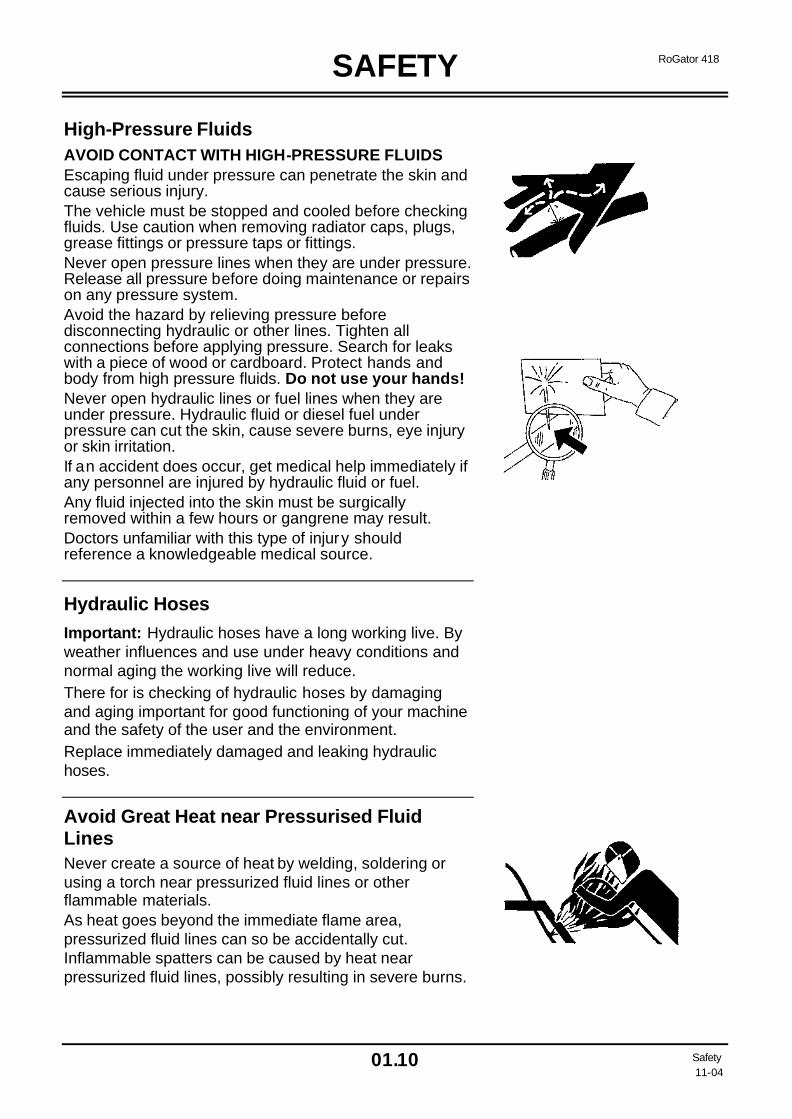
High-Pressure Fluids AVOID CONTACT WITH HIGH-PRESSURE FLUIDS Escaping fluid under pressure can penetrate the skin and cause serious injury. The vehicle must be stopped and cooled before checking fluids. Use caution when removing radiator caps, plugs, grease fittings or pressure taps or fittings. Never open pressure lines when they are under pressure. Release all pressure before doing maintenance or repairs on any pressure system. Avoid the hazard by relieving pressure before disconnecting hydraulic or other lines. Tighten all connections before applying pressure. Search for leaks with a piece of wood or cardboard. Protect hands and body from high pressure fluids. Do not use your hands! Never open hydraulic lines or fuel lines when they are under pressure. Hydraulic fluid or diesel fuel under pressure can cut the skin, cause severe burns, eye injury or skin irritation. If an accident does occur, get medical help immediately if any personnel are injured by hydraulic fluid or fuel. Any fluid injected into the skin must be surgically removed within a few hours or gangrene may result. Doctors unfamiliar with this type of injury should reference a knowledgeable medical source.
Hydraulic Hoses Important: Hydraulic hoses have a long working live. By weather influences and use under heavy conditions and normal aging the working live will reduce. There for is checking of hydraulic hoses by damaging and aging important for good functioning of your machine and the safety of the user and the environment. Replace immediately damaged and leaking hydraulic hoses.
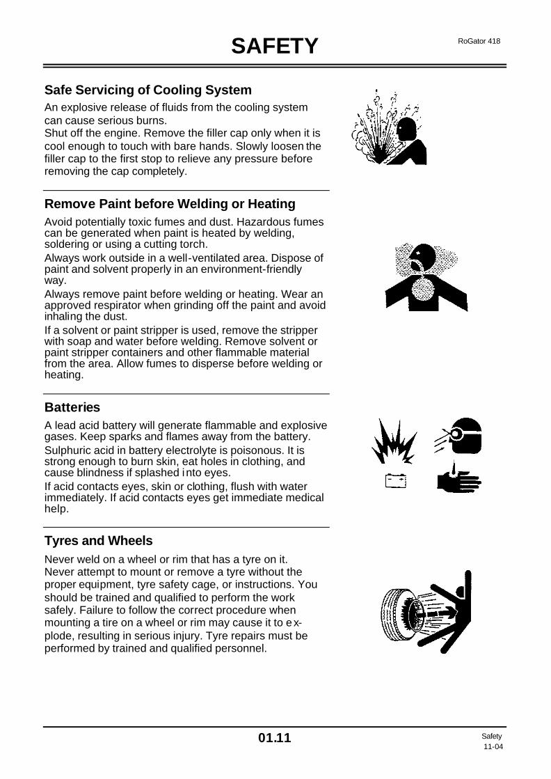
Avoid Great Heat near Pressurised Fluid Lines Never create a source of heat by welding, soldering or using a torch near pressurized fluid lines or other flammable materials. As heat goes beyond the immediate flame area, pressurized fluid lines can so be accidentally cut. Inflammable spatters can be caused by heat near pressurized fluid lines, possibly resulting in severe burns.
SAFETY
01.11 Safety 11-04
RoGator 418
Safe Servicing of Cooling System An explosive release of fluids from the cooling system can cause serious burns. Shut off the engine. Remove the filler cap only when it is cool enough to touch with bare hands. Slowly loosen the filler cap to the first stop to relieve any pressure before removing the cap completely.
Remove Paint before Welding or Heating Avoid potentially toxic fumes and dust. Hazardous fumes can be generated when paint is heated by welding, soldering or using a cutting torch. Always work outside in a well-ventilated area. Dispose of paint and solvent properly in an environment-friendly way. Always remove paint before welding or heating. Wear an approved respirator when grinding off the paint and avoid inhaling the dust. If a solvent or paint stripper is used, remove the stripper with soap and water before welding. Remove solvent or paint stripper containers and other flammable material from the area. Allow fumes to disperse before welding or heating.
Batteries A lead acid battery will generate flammable and explosive gases. Keep sparks and flames away from the battery. Sulphuric acid in battery electrolyte is poisonous. It is strong enough to burn skin, eat holes in clothing, and cause blindness if splashed into eyes. If acid contacts eyes, skin or clothing, flush with water immediately. If acid contacts eyes get immediate medical help.
Tyres and Wheels Never weld on a wheel or rim that has a tyre on it. Never attempt to mount or remove a tyre without the proper equipment, tyre safety cage, or instructions. You should be trained and qualified to perform the work safely. Failure to follow the correct procedure when mounting a tire on a wheel or rim may cause it to ex-plode, resulting in serious injury. Tyre repairs must be performed by trained and qualified personnel.
SAFETY
01.12 Safety 11-04
RoGator 418
Dispose of Waste Properly Improper disposal of potentially harmful waste can pose a threat to the environment. Potentially harmful waste used with Ag-Chem Europe BV vehicles includes such items as oil, fuel, filters, fluids and batteries. Use leak-proof containers when draining fluids. Never pour harmful waste onto the ground, down a drain, or into any water source. Air conditioning refrigerants escaping into the atmosphere can damage the earth’s atmosphere. Government regulations require a certified air conditioning service centre to recover and recycle used air conditioning refrigerants.
Mobile Radio Installations Under no circumstances should a mobile radio antenna be mounted to the rear of the cab or antenna cable and be routed near harness or electrical system controllers or near operator controls. Failure to follow these precautions could expose the operator to radio frequency energy levels higher than recommended by the European Directive 89/336/EEC: Electro-Magnetic Compatibility, and/or could cause undesirable performance of electrically controlled systems.

SAFETY
01.13 Safety 11-04
RoGator 418
Location of Safety and Service Decals Chassis
WARNING!
Carefully read and understand all safety signs on your RoGator. Failure to read and understand all safety signs may result in (fatal) injuries if you are unaware of a safety hazard. Make sure new equipment components and repair parts include the current safety signs.
1 Caution - Hot surface (E720604) 7 Use only Diesel specified to EN590 (E552394) 2 Don’t open hood with engine running (E720561) 8 Decal “418” (E558992) 3 Caution - Read operator's manual (E720568) 9 Warning – Stay outside the rotation area of the
steps. (E558577) 4 Grease gun (E720569) 10 Decal “RG418” (E558991) 5 Beware of leaking hydraulic lines / hoses (E720709) 11 No clearance for person in the working area of this
machine (E720737) 6 System charged with R134A refrigerant (E720742) 12 Warning – Do not ride or stand in this area when
machine or booms are in motion (238783)
NOTE: Replacement safety signs are available by Ag-Chem Europe BV.
418
ROGATOR 418

SAFETY
01.14 Safety 11-04
RoGator 418
Location of Safety and Service Decals Chassis 13 Decal “ROGATOR” (E720506) 16 Caution – Extern hydraulic system is filled with ISO
VG 46 Oil (E558586) 14 Warning – Do not put limbs between the wheels
and frame when the engine runs. Tires and wheels can move without warning and crush you. You can be killed or seriously injured (E558580)
17 Caution - The vehicle will swing as a result of the 4-wheelsteering (E558574)
15 Remote control outside cab (E558990)
ROGATOR 418
418
ROGATOR
00
R E S 2R E S 1
1
RPMRPM

SAFETY
01.15 Safety 11-04
RoGator 418
Location of Safety and Service Decals Cabine 18 Warning – Keep booms and all antennas away from
power lines. Do not attempt to enter the vehicle if it is in contact with power lines. Electrocution will result. (E558568)
23 Before starting the engine, first check the oil level of the engine and hydraulic tanks. (E720735)
19 Caution – WHEEL MOUNTING PROCEDURE (E558638)
24 Emergency Exit (E720738)
20 Serial number and CE plate (E770002) 25 Warning – If you want to fold in or out the steps, be aware that there are no persons inside the rotation area of the steps (E558571)
21 If the machine is tipping over, do not try to jump off, but hold firmly on the steering wheel. (E720741)
26 Caution – PARKING BRAKE Engage the parking brake before you leave the cab. If you will use the parking brake as a service brake, this will result in damaging the hydraulic system.(E558565)
22 Warning – DO NOT EXCEED TYRE SPEED RATING Tires may overheat and fail causing personal injury or death. When vehicle is loaded, reduce speed further according to the tire chart. (E588530)
27 Decal cabine heater and Fan. (E558989)
18 25 3 19 26 23 21 22 27
3 20 24
INTRODUCTION
02.1 Introduction 11-04
RoGator 418
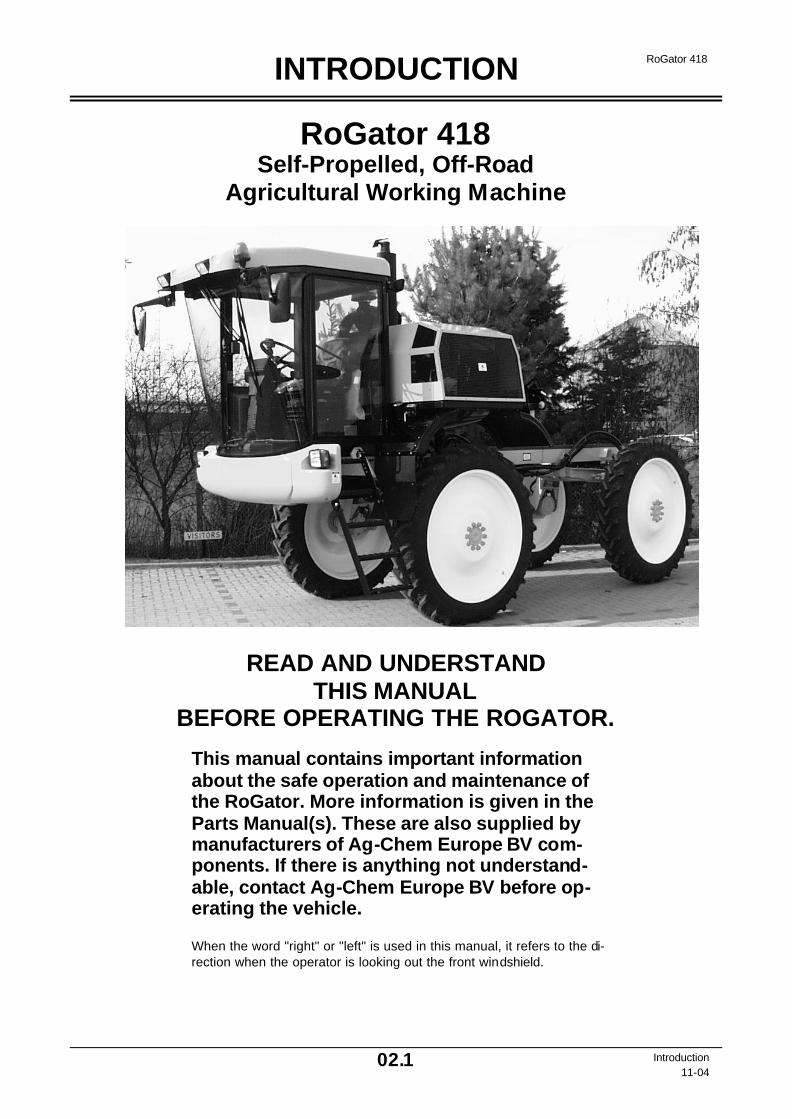
RoGator 418 Self-Propelled, Off-Road
Agricultural Working Machine
READ AND UNDERSTAND THIS MANUAL
BEFORE OPERATING THE ROGATOR.
This manual contains important information about the safe operation and maintenance of the RoGator. More information is given in the Parts Manual(s). These are also supplied by manufacturers of Ag-Chem Europe BV com-ponents. If there is anything not understand-able, contact Ag-Chem Europe BV before op-erating the vehicle.
When the word "right" or "left" is used in this manual, it refers to the di-rection when the operator is looking out the front windshield.

INTRODUCTION
02.2 Introduction 11-04
RoGator 418
Identification Serial Number Identification Plates Write the serial numbers in the spaces provided. Use these numbers when referring to the RoGator. Ag-Chem Europe BV identification plate with the serial number is located on the front panel of the compartment in the cabin.
AG-CHEM SERIAL NUMBER Identification plate with serial number
Engine Serial Number The engine serial number plate is located on the right-hand side of the engine. The following information is stamped on the serial number plate: ENGINE SERIAL NUMBER (1)
APPLICATION DATA OR TYPE (2)
Engine Serial Number Plate

INTRODUCTION
02.3 Introduction 11-04
RoGator 418
Hydrostatic Drive
CAUTION!
The drive system of the RoGator is hydrostatic. After carefully reading and having understood the manual, practice driving with the RoGator in a safe area be-fore driving with the RoGator in the field or on the road. Accidents or damage can result if you are not used to driving with a hydrostatic drive and re-spond improperly to certain situations.
Traction Control Lever, Pump and Wheel Motors. Pushing the traction control lever forward or back modulates the swash plate in the pumps, allowing hydraulic oil under pressure to flow to the four wheel motors in a closed system. The traction control lever is connected to the pumps, which control the speed of the vehicle by regulating the amount of oil flowing to the wheel motors. The RoGator has two possible travel mode switch positions: 1. Field position 2. Road position. When driving with the travel mode switch in the field position, the vehicle speed is not controlled with the engine speed but with the position of the traction control lever. In this situation the hand throttle must be used. In the road position this lever is moved forward or back as far as possible. The speed of the machine is determined by the accelerator pedal.
Engine The Diesel engine drives the pumps. Low-pressure Pump The low-pressure pump (a part of the traction pump) generates a low pressure for: 1. Flushing the system, 2. Modulating the traction pump. Combined Cooler The oil part of the combined cooler cools the flush-ing and leakage oil before it flows back to the hy-draulic oil tank. Tank and Filter The complete return oil flows through the suction and return oil filter. A part of the filtered oil flows to the intake line of the low-pressure pumps and the rest goes to the hydraulic tank.

INTRODUCTION
02.4 Introduction 11-04
RoGator 418
Break-in Period
First 100 Hours of Operation IMPORTANT: Change the engine oil and oil filter after the first 100-150 service hours. This should be done in connection with a 100 to 150 hour maintenance service performed by AG-Chem Europe b.v. after making an appointment with the Service Centre. Refer to the section entitled "Maintenance" for the engine oil and engine oil filter specifications. The running-in instructions can be found in the engine operat-ing and maintenance manual. Hydraulic System IMPORTANT: Replace the filter element of the hydraulic suction/return line filter after the first 100 to 150 service hours. (See "Maintenance" section.) Check the oil level daily and watch for any possible leaks. Engine Coolant Level Check the engine coolant level and watch for any possible leaks.
WARNING!
The cooling system is pressur-ised. Scalding can occur if con-tacting hot coolant. Do not loosen the coolant reservoir cap when the coolant is hot.
Wheel Mounting Bolts 1. Loosen each wheel mounting bolt 1/4 turn every
10 hours during the first 50 hours of operation and then tighten opposite bolts to a torque of 250 Nm.
2. Retighten all bolts, but now to a torque of 515 Nm.
3. Repeat step 2 every 500 service hours. For procedure see P. 6.11.
Maintenance Schedule Check all items shown under the daily section of the maintenance schedule, every day the machine is in use.
Chassis and Cabin Modifications IMPORTANT: It is not allowed to modify the vehicle or auxiliary parts not approved by Ag-Chem Europe b.v. or by the manufacturer of the vehicle. IMPORTANT: To prevent damage to the wiring and hoses, never drill holes into the cabin. Be particularly cautious with vertical pipes.
Towing the RoGator If there is a problem that cannot be corrected on the spot, transport the vehicle instead of towing it if at all possible.
Towing with Engine Operable The vehicle may be towed a short distance if nec-essary. IMPORTANT: When towing, run the engine at idle speed to provide hydraulic power for steer-ing and to release the parking brake. The ball valves must be set at the traction drive mani-fold so that the oil can still circulate without pressure. Do not tow the vehicle at a speed of more than 8 km/h. Towing with Engine Disabled IMPORTANT: If the engine can not be run, the parking brake must be released. Do not exceed a speed of 5 km/h as steering is more difficult. Also operate the ball cock valves. IMPORTANT: if there is a problem that can not be corrected in the field, TRANSPORT THE VEHICLE INSTEAD OF TOWING THE VEHICLE IF AT ALL POSSIBLE. Towing the vehicle is not recommended, except in cases of emergency.
CAUTION!
WARNING: Do not use a towing rope, for it will produce a whip-lash in case the rope breaks. This can result in personal in-jury. Therefore always use a tow bar.
INTRODUCTION
02.5 Introduction 11-04
RoGator 418
RoGator Towing Procedure 1. If at all possible, let the engine run when towing
the vehicles to provide sufficient hydraulic power for the brakes. If the engine may NOT run, be sure that there is enough hydraulic power for a LIMITED number of braking.
2. It is recommended to use a tow bar instead of a towing rope.
3. If the engine is NOT running, disengage the parking brake by hand. Do this as follows:
I. Put chocks in front of and behind the wheels
to prevent the RoGator from rolling. II. Remove the rubber plug (Pos. 5) at the rear
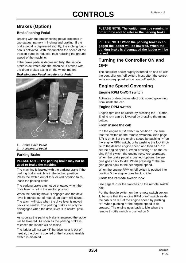
wheel motors. III. Place the spacer (60x60x8) (Pos. 9) on the
brake (Pos. 2). The spacer should be about 280 mm long. In the centre of the spacer should be a hole with a diameter of 16.5 mm.
IV. Insert a M16 x 120 screw (Pos. 7) through the spacer and turn the screw tightly into the piston. Tighten the M16 nut (Pos. 8) nut until the motor shaft (Pos. 1) can rotate freely. The parking brake is now disengaged.
4. The vehicle must be in NEUTRAL. Parking brake disengagement
5. Open the lock valve at the centre of the chassis. 6. The vehicle can be towed.
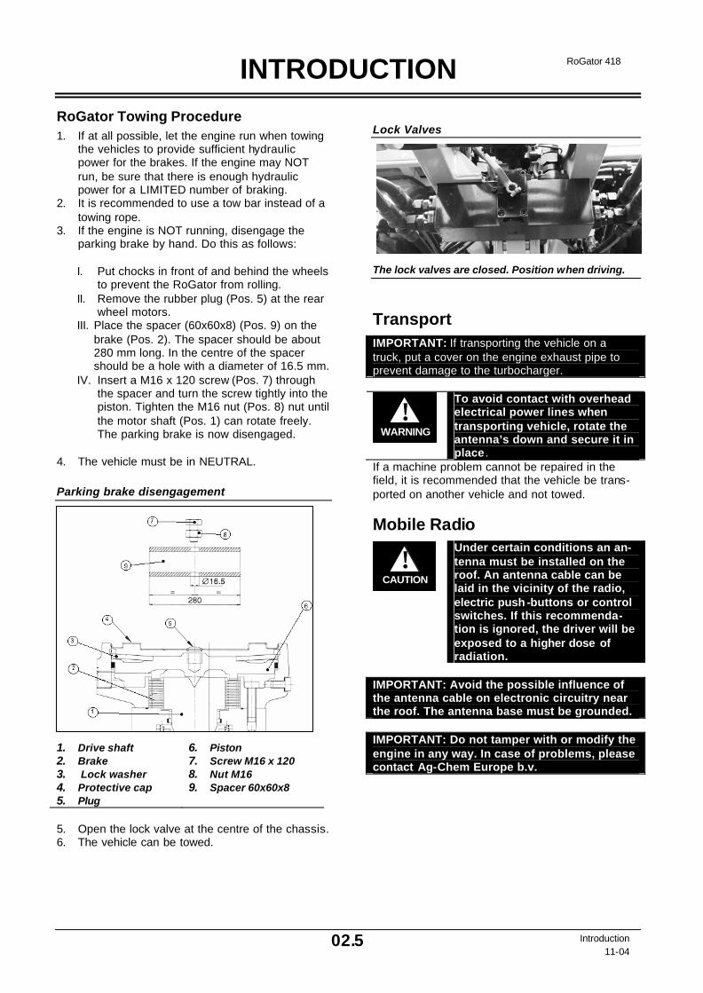
Lock Valves
The lock valves are closed. Position when driving.
Transport IMPORTANT: If transporting the vehicle on a truck, put a cover on the engine exhaust pipe to prevent damage to the turbocharger.
WARNING!
To avoid contact with overhead electrical power lines when transporting vehicle, rotate the antenna’s down and secure it in place .
If a machine problem cannot be repaired in the field, it is recommended that the vehicle be trans-ported on another vehicle and not towed.
Mobile Radio
CAUTION!
Under certain conditions an an-tenna must be installed on the roof. An antenna cable can be laid in the vicinity of the radio, electric push -buttons or control switches. If this recommenda-tion is ignored, the driver will be exposed to a higher dose of radiation.
IMPORTANT: Avoid the possible influence of the antenna cable on electronic circuitry near the roof. The antenna base must be grounded. IMPORTANT: Do not tamper with or modify the engine in any way. In case of problems, please contact Ag-Chem Europe b.v.
1. Drive shaft 2. Brake 3. Lock washer 4. Protective cap 5. Plug
6. Piston 7. Screw M16 x 120 8. Nut M16 9. Spacer 60x60x8

INTRODUCTION
02.6 Introduction 11-04
RoGator 418
Location of Components
1. Engine oil dipstick/oil filler opening 2. Engine oil filter 3. Fuel filter 4. Primary and inner air filter elements 5. Coolant reservoir 6. Coolant filler opening 7. Electrical system earth switch 8. Batteries 9. Hydraulic tank 10. Hydraulic tank suction/return line filter 11. Hydraulic tank filler opening
12. Fuel tank 13. Fuel tank filler opening 14 Wheel motor 15. Traction pump 16. Gear pump 17. Compressed air tanks 18. Ladder 19. Fuse panel 20. Cooler 21. Exhaust 22. Leakage oil filter
ROGATOR 418
418
ROGATOR
418
ROGATOR 418
00
1
1 2 3
4
5 6
7
8 9
10 11
12
13 14 14
15 16
17
18
18
19
20
21
22

CONTROLS
03.1 Controls
11-04
RoGator 418
Operation Turn Signal, Lights and Horn Lever
Pull the lever forward to turn the right turn signal lever on.
Push the lever back to turn the left turn signal lever on.
Rotate the cap on the lever to switch on the parking lights or the low beam.
Move the lever to the right to switch the lights from high beam to dip beam.
Move the lever to the right to switch from dip beam to high beam.
Press the top of the lever to sound the horn.
Turn Signal, Lights and Horn Lever
1. Turn signal, lights and horn lever
Adjustment of the Steering Wheel
Unlock the steering wheel by rotating the handel (1) on the left side of the steering column. Tilt the steer-ing wheel in the direction you want. Pull the steering wheel out to the desired position. Tighten the handel on the left side of the steering column, to lock the steering wheel in the desired position.
Steeringwheel console
1. Adjustment handel steering column.
Accelerator Pedal Remark: The accelerator pedal is used mainly when driving on public roads. In the field the throttle should be used (field/street switch) in the "field" position. The advan-tage of driving with the throttle is that the engine speed remains much more constant, and this raises the quality of the spraying and spreading.
Pressing on the accelerator pedal increases the engine speed. If the traction control lever is not in neutral position, the ground speed of the machine will increase.
Releasing the right foot from the pedal decreases the engine speed, reducing the ground speed of the machine.

CONTROLS
03.2 Controls
11-04
RoGator 418
Traction Control Lever Positions of the Traction Control Lever
(1) Neutral Place the lever in the left cut-out to put the vehicle in neutral. (2) Driving Forwards Depending upon the position of the field/street switch, two methods are possible: Field Position: The machine is being driven with the throttle. Move the lever slowly forward to increase the speed during forward travel.
Move the lever slowly back to reduce the speed dur-ing forward travel. Road Position: The machine is being driven with the accelerator pedal. Allow the engine to idle (about 800 rpm).
Move the lever forward as far as possible (to select the direction of travel).
Depress the accelerator pedal to increase the en-gine speed during forward travel. Allow the accelera-tor pedal to come up to decrease the speed. (3) Reversing Depending upon the position of the field/street switch, two methods are possible: Field Position: The machine is being driven with the throttle. Move the lever slowly back from the neutral position to increase the reversing speed. Move the lever slowly forward to reduce the reversing speed. Road Position: The machine is being driven with the accelerator pedal. Allow the engine to idle (about 800 rpm). Move the lever back as far as possible (to select the direction of travel).
Depress the accelerator pedal to increase the en-gine speed during reversing. Allow the accelerator pedal to come up to decrease the speed. In case the vehicle is not braked fast enough with the trac-tion control lever or the accelerator pedal, it is pos-sible to use the brake/inching pedal (see operation of brake/inching pedal on page 3.5).
Positions of the Traction Control Lever
1. Neutral 2. Driving forward 3. Reversing
CAUTION!
The RoGator is a hydrostatically driven vehicle. The machine may only be operated after having read and understood this manual.
CAUTION!
Do not exceed the recommended speed of the tyres or the maxi-mum speed of the vehicle (40 km/h). Exceeding the recom-mended tyre speed may lead to accidents.

CONTROLS
03.3 Controls
11-04
RoGator 418
Adjustment of the Traction Control Lever Position:
1. Rotation of the traction control lever: Loosen the lock nut and the knurled nut under the trac-tion control lever. Then turn the traction control lever to the desired position. Subsequently tighten the clamping nut and the knurled nut.
2. Adjusting the traction control lever console: Loosen the screws beside the armrest, slide the console forward or backwards and retighten the screws.
Adjustment of Traction Control Lever Position
1. Adjustment bolts
1
CONTROLS
03.4 Controls
11-04
RoGator 418
Brakes (Option) Brake/Inching Pedal
Braking with the brake/inching pedal proceeds in two stages, namely in inching and braking. If the brake pedal is depressed slightly, the inching func-tion is activated. With this function the speed of the traction pump is reduced, thus reducing the ground speed of the machine.
If the brake pedal is depressed fully, the service brake is activated and the machine is braked with the drum brakes acting on the wheel motors.
Brake/Inching Pedal, accelerator Pedal
1. Brake / Inch Pedal 2. Accelerator Pedal
Parking Brake
PLEASE NOTE: The parking brake may not be used to brake the machine.
The machine is braked with the parking brake if the parking brake switch is in the locked position. Press the switch out of this locked position to re-lease the parking brake.
The parking brake can not be engaged when the drive lever is not in the neutral position.
When the parking brake is engaged and the drive lever is moved out of neutral, an alarm will sound. The alarm will stop when the drive lever is moved back into neutral. The parking brake can only be disengaged when the drive lever is in neutral posi-tion.
As soon as the parking brake is engaged the ladder will be lowered. As soon as the parking brake is released the ladder will be raised.
The ladder will not work if the drive lever is out off neutral, the door is opened or the hydraulic enable switch is disabled.
PLEASE NOTE: The ignition must be running in order to be able to release the parking brake.
PLEASE NOTE: When the parking brake is en-gaged the ladder will be lowered. When the parking brake is disengaged the ladder will be raised.
Turning the Controller ON and OFF The controller power supply is turned on and off with the controller on / off switch. Most often the control-ler is also equipped with an on / off switch.
Engine Speed Governing Engine RPM On/Off switch
Activates or deactivates electronic speed governing from inside the cab.
Engine RPM switch
Engine rpm can be raised by pressing the + button. Engine rpm can be lowered by pressing the minus button.
From inside the cab
Put the engine RPM switch in position 1, be sure that the switch on the remote switchbox (see page 3.7) is on 0. Set the engine speed by pushing “+” on the engine RPM switch, or by pushing the foot throt-tle to the desired engine speed and then hit “+” to set the engine speed. When pressing “-“ on the en-gine RPM switch, the engine revs. Are decreased. When the brake pedal is pushed (option), the en-gine goes back to idle. When pressing “-“ the en-gine goes back to the set engine speed.
When the engine RPM on/off switch is pushed into position 0 the engine goes back to idle.
From the remote switch box
See page 3.7 for the switches on the remote switch box.
Put the throttle switch on the remote switch box on 1, be sure that the engine RPM on/off switch inside the cab is on 0. Set the engine speed by pushing “+”. When pushing “-“ the engine speed is de-creased. The engine goes back to idle when the remote throttle switch is pushed on 0.
1 2

CONTROLS
03.5 Controls
11-04
RoGator 418
1 2 3
4 5 6 7 8 9 10
11 12 13 14 15 16 17
22212019
18
Instrument Panel
1. Field / Road switch 2. All-wheel-steering On / Off / Auto 3. Regulating computer On / Off switch 4. Engine RPM On/Off switch 5. Engine RPM switch 6. Hydraulic Enable switch 7. Not used 8. Spraypump On / Off switch 9. Dubbel foam switch 10. Differential Lock On / Off switch (Optional) 11. Folding / Unfolding Booms switch 12. Second Fold switch
13. Half Fold switch 14. Purge switch 15. Regulation sprayer Auto / Manual switch 16. Increase / Decrease pressure spray system
switch 17. Not used 18. Power Socket cigaret lighter style. 19. Track width lock switch. 20. Front axle track width switch. 21. Rear axle track width switch. 22. Not used 23. Warning light Green Differential Lock On
23

CONTROLS
03.6 Controls
11-04
RoGator 418
Ignition Switch The ignition switch has three positions.
CAUTION!
PLEASE NOTE: Do not let the starter run more than 30 se c-onds. Allow the starter to cool for 2 minutes before actuating the starter again.
0. MACHINE OFF. When the key is in this posi-tion, the machine and the accessories are turned off.
1. ON. This is the normal position for the operation of the vehicle.
2. START. In this position the engine is started with the starter.
PLEASE NOTE: The ignition switch can only be set to START (2) only ONCE. Return the key fully to the OFF position and repeat the start-ing procedure.
Suspension Automatic Suspension Switch
Operating this switch puts the suspension in the automatic mode.
Manual Suspension Switch
With this switch it is possible to raise or lower the suspension manually.
Driving in the Field or on the Road For driving on public roads the field / road switch is set to the "road" position, and for working in the field to the "field" position.
When this switch is in the "road" position, the fol-lowing condition applies:
• 4-wheel steering is switched off.
4-Wheel Steering PLEASE NOTE: The 4-wheel steering can only be selected in the field position.
4-Wheel Steering Switch
With this switch it is possible to select three posi-tions.
Automatic: This is the working position for the 4-wheel steering. When the switch is in this position, the 4-wheel steering can be switched on and off with the foot switch.
Manual: This is the calibration position for the 4-wheel steering.
Zero Position: The 4-wheel steering is now turned off, depressing the foot switch has no effect.
4-Wheel Steering Foot Switch
4-Wheel Steering foot switch
Switching the Spraycomputer On/Off With the switch Spraycomputer On/Off the com-puter will be supplied with power. The spraycom-puter its self has also an ON/Off switch.
CONTROLS
03.7 Controls
11-04
RoGator 418
Remote Throttle Control Remote Throttle Control Box
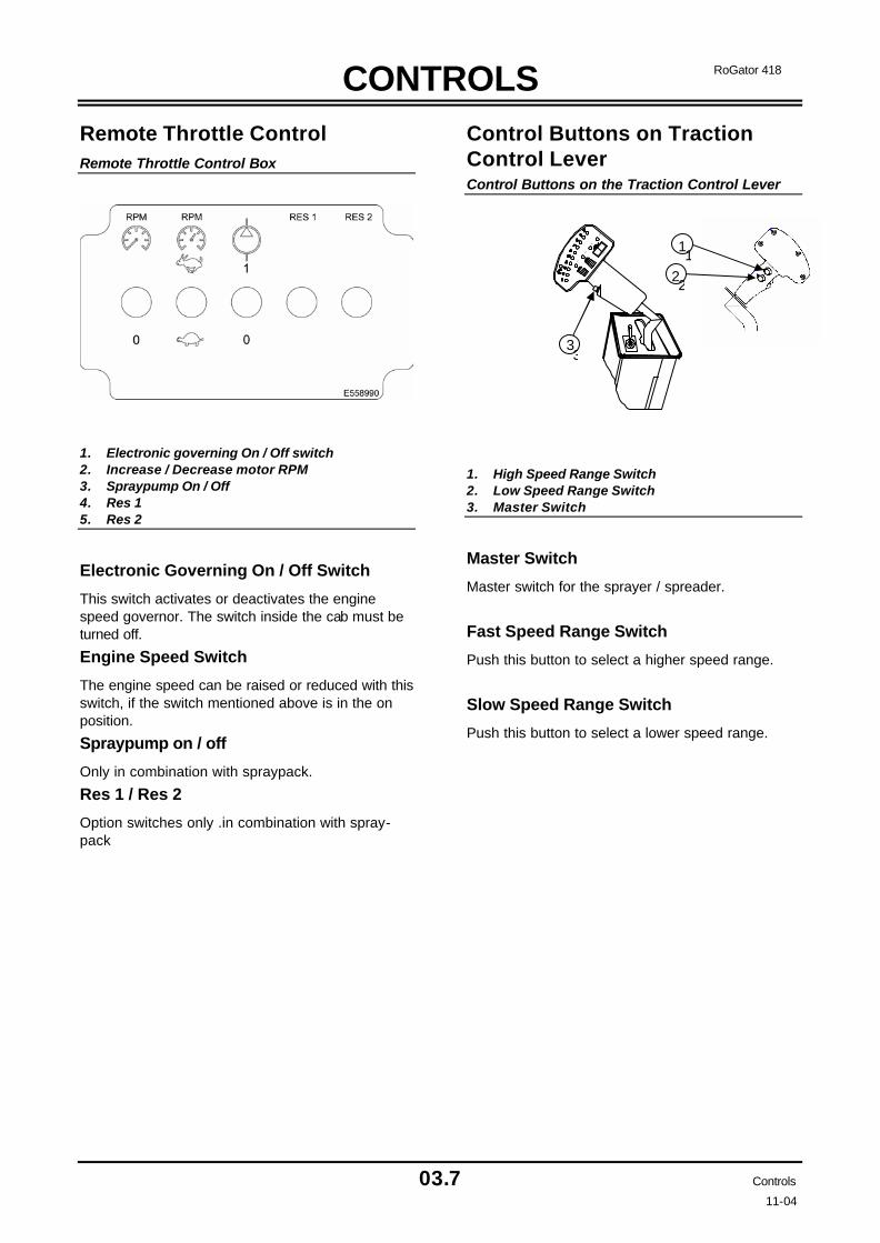
1. Electronic governing On / Off switch 2. Increase / Decrease motor RPM 3. Spraypump On / Off 4. Res 1 5. Res 2
Electronic Governing On / Off Switch
This switch activates or deactivates the engine speed governor. The switch inside the cab must be turned off.
Engine Speed Switch
The engine speed can be raised or reduced with this switch, if the switch mentioned above is in the on position.
Spraypump on / off
Only in combination with spraypack.
Res 1 / Res 2
Option switches only .in combination with spray-pack
Control Buttons on Traction Control Lever Control Buttons on the Traction Control Lever
1. High Speed Range Switch 2. Low Speed Range Switch 3. Master Switch
Master Switch
Master switch for the sprayer / spreader.
Fast Speed Range Switch
Push this button to select a higher speed range.
Slow Speed Range Switch
Push this button to select a lower speed range.
LII
L I
SI
E5584
77
SII
1
2
33
1
2

CONTROLS
03.8 Controls
11-04
RoGator 418
Lighting and door handling of the cab Door Latch
The door has a button handle on the exterior and a lever on the inside.
To open the door from the outside, press the button and pull the door handle.
To open the door from the inside, press the door lever down and push the hand rail.
To lock or unlock the door, insert the key into the button on the outside of the door and turn the key clockwise to lock the door and anti-clockwise to unlock the door. Subsequently return the key to the original position and remove the key.
Doorlatch
Sun Visor
Pull the sun visor down. Slide the sun visor up.
Cabin Light Switch
Press the switch up to turn on the cabin lights when the door is open. As soon as the door is closed the lights turn off.
Press the switch to the lowest position to turn on the ceiling lights.
The ceiling lights are generally off when the switch is in the centre position.
Cabin Light Switch
1. Door operated 2. On 3. Off
1
2
CONTROLS
03.9 Controls
11-04
RoGator 418
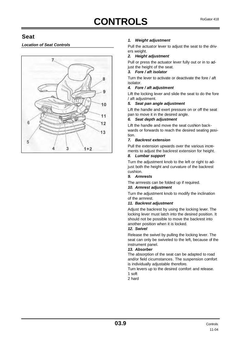
Seat Location of Seat Controls
1. Weight adjustment
Pull the actuator lever to adjust the seat to the driv-ers weight. 2. Height adjustment
Pull or press the actuator lever fully out or in to ad-just the height of the seat. 3. Fore / aft isolator
Turn the lever to activate or deactivate the fore / aft isolator. 4. Fore / aft adjustment
Lift the locking lever and slide the seat to do the fore / aft adjustment. 5. Seat pan angle adjustment
Lift the handle and exert pressure on or off the seat pan to move it in the desired angle. 6. Seat depth adjustment
Lift the handle and move the seat cushion back-wards or forwards to reach the desired seating posi-tion. 7. Backrest extension
Pull the extension upwards over the various incre-ments to adjust the backrest extension for height. 8. Lumbar support
Turn the adjustment knob to the left or right to ad-just both the height and curvature of the backrest cushion. 9. Armrests
The armrests can be folded up if required. 10. Armrest adjustment
Turn the adjustment knob to modify the inclination of the armrest. 11. Backrest adjustment
Adjust the backrest by using the locking lever. The locking lever must latch into the desired position. It should not be possible to move the backrest into another position when it is locked. 12. Swivel
Release the swivel by pulling the locking lever. The seat can only be swiveled to the left, because of the instrument panel. 13. Absorber The absorption of the seat can be adapted to road and/or field cicumstances. The suspension comfort is individually adjustable therefore. Turn levers up to the desired comfort and release. 1 soft 2 hard

CONTROLS
3.10 Controls
11-04
RoGator 418
External Lighting and Temperature Control Panel in the Cabin
1. Work Light Switch One 8. Stop Lamp 2. Work Light Switch Two 9. Warning / Cold start Lamp 3. Work Light Switch Three 10. Automatic Suspension Switch 4. Work Light Switch Four 11. Manual Suspension Switch 5. Beacon Light Switch 12. Temperature Control knob 6. Hazard Warning Light Switch 13. Air Conditioner / Heater Switch 7. Not Used 14. Blower Speed Switch
1. Work Light Switch One
The switch operates:
Left front working light.
Press the top of the switch to turn the work light controlled by work switch one on.
Press the bottom of the switch to turn the light off.
2. Work Light Switch Two
The switch operates:
Right front working light.
Press the top of the switch to turn the work light controlled by work switch one on.
Press the bottom of the switch to turn the light off.
3. Work Light Switch Three
The switch operates:
Left rear working light.
Press the top of the switch to turn the work light controlled by work switch one on.
Press the bottom of the switch to turn the light off.
4. Work Light Switch Four
The switch operates:
Right rear working light.
Press the top of the switch to turn the work light controlled by work switch one on.
Press the bottom of the switch to turn the light off.
5. Beacon Light Switch - Option
Press the top of the switch to turn the light on.
Press the bottom of the switch to turn the light off.
6. Hazard Warning Switch (Orange Flashing Warning Lights)
Press the top of the switch to turn the hazard lights on.
Press the bottom of the switch to turn the lights off.
When the hazard warning light switch is on, the hazard warning light switch will illuminate and cycle.
The left and right turn signal indicator lights are also illuminated.
IMPORTANT: Operation of the beacon light must comply with state and local regulations.
7. Not used
8. Stop Lamp
9. Warning / Cold Start Lamp
10. Automatic Suspension Switch
Operating this switch puts the suspension in the automatic mode.
11. Manual Suspension Switch
With this switch the suspension can be raised or lowered manually.
12. Temperature Control Knob
Turn the knob counter-clockwise to increase air temperature in the cab.
Turn the knob clockwise to decrease air tempera-ture in the cab.
13. Air Conditioner / Heater Switch
Move to centre position for the heat and blower fans to turn on.
Move to top position for the Air Conditioner and blower fans to turn on.
Move to bottom position for off.
14. Blower Speed Switch
There are 3 speeds: Low, Medium and High. The top position is high speed.
PLEASE NOTE: The blowers run only if the air conditioning/heater switch is on (either in the heater or airconditioning position)

INSTRUMENTS
04.1 Instruments
11-04
RoGator 418
Instrument Panel Dashboard
1. Turn signal, lights and horn lever 2. Neutral gear 3. Third gear selected 4. First gear selected 5. Second gear selected 6. Rear axle middle position 7. All-steer mode 8. Two-wheel-steer mode 9. Front axle in middle position 10. Speedometer 11. Battery Voltage gauge 12. Fuel level gauge
13. Left turn signal indicator 14. High beams on 15. Parkingbrake on 16. Right turn signal indicator 17. Hydraulic oilfilter plugged 18. Boost pressure too low 19. Hydraulic oil temperature too high 20. Hydraulic oil level too low 21. Parking brake switch 22. Windshield washer switch 23. Windshield wiper switch 24. Reset button speedometer

INSTRUMENTS
04.2 Instruments
11-04
RoGator 418
Instrument Panel Dashboard All displays, gauges and indicator lamps operate when the key switch is in the “ON” position.
Speedometer The speedometer indicates the ground speed of the RoGator in km/h.
WARNING!
Operate the vehicle ONLY at safe speeds. Fatal injuries can result if the vehicle becomes unstable and you lose control of the vehicle.
Fuel Level Gauge The fuel level gauge shows fuel level in the fuel tank.
Battery voltage gauge Displays the battery state and rate of charge. With the ignition switched on and the engine stopped, the voltmeter should display (approx.) 12.0 V. If not, the battery charge is too low. The voltage displayed should be between 12.0 and 14.5 volts when the engine is running.
High Beam ON Indicator Light The high beam on indicator illuminates when the headlights are on high beam.
Parking Brake Warning Light The parking brake warning illuminates when the parking brake is engaged.
Left Turn Signal Light This indicator light illuminates when the left turn signal or the hazard warning lights are switched on. The turn signal must be deactivated manually.
Right Turn Signal Light This indicator light illuminates when the left turn signal or the hazard warning lights are switched on. The turn signal must be deactivated manually.
Suction/Return Line Filter and Leak Oil Filter Indicator Light This indicator light illuminates when the suc-tion/return line filter or the leak oil filter is becoming restricted. The filters must be changed.
Boost Pressure Indicator Light This indicator light illuminates when the boost pres-sure drops below 16 bar.
Hydraulic Oil Level Indicator Light This indicator light illuminates when the hydraulic oil level in the hydraulic oil tank is too low.
Oil Temperature Indicator Light This indicator light illuminates when the temperature of the hydraulic oil is too high. Probably the oil is not being cooled.
Transmission in Neutral Indicator Light The transmission in neutral indicator illuminates when the transmission is in neutral.
Transmission in First Gear Indicator Light The transmission in first gear indicator illuminates when the transmission is in first gear.
Transmission in second Gear Indicator Light The transmission in second gear indicator illumi-nates when the transmission is in second gear.
Transmission in Third Gear Indicator Light The transmission in third gear indicator illuminates when the transmission is in third gear.
All-Steer Mode Indicator Light The all-steer mode indicator light illuminates when the machine is in all-steer mode.
Two-Wheel-Steer Mode Indicator Light The two-wheel-steer mode indicator light illuminates when the machine is in two-wheel-steer mode.
Front Axle in Middle Position Indicator Light The front axle in middle position indicator light illu-minates when the front axle is in the middle posi-tion.
Rear Axle in Middle Position Indicator Light The rear axle in middle position indicator light illu-minates when the rear axle is in the middle position.
Reset button speedometer Resets the speedometer to zero.

INSTRUMENTS
04.3 Instruments 11-04
RoGator 418
General Description GEM The GEM is a compact, robust panel-mountable module that enables a user to remotely request and display engine data. The unit utilises an indus-try-standard protocol to connect to the engine via either an SAE J1939 CAN data link. The GEM incorporates a graphics LCD with five ‘soft’ keys mounted at the bottom of the LCD, pro-viding a very flexible and intuitive Human-Machine Interface (HMI). Associated with the ‘soft’ keys is a graphical menu structure that uses easily understood icons to indi-cate the key’s current function. This enables the operator to select the required engine data and display it in the following formats:- • Analogue gauges • Digital data • Graphs • Multi-data (a combination of the above) • Current active alarm messages Additionally, various diagnostic screens are acces-sible, allowing detailed investigation of the en-gine’s data stream.
Getting Started After power is applied the start-up screen shown below will be displayed for approximately 7 sec-onds. If the unit bleeps with a low-pitched tone, the self-test has failed. Refer to the User Guide sec-tion for further details.
Once the self-test is complete, the display will change to show the default engine data screen. Should the screen need adjusting to improve legi-bility, press the blue key to select the Contrast and lighting menu. If the GEM is connected to an active stream of engine data, it will now start displaying readings on the gauges shown on the LCD screen. For further operating instructions, please refer to the following section of this document.
The Start-up Screen
‘Soft’ Keys
Key 1
Key 5
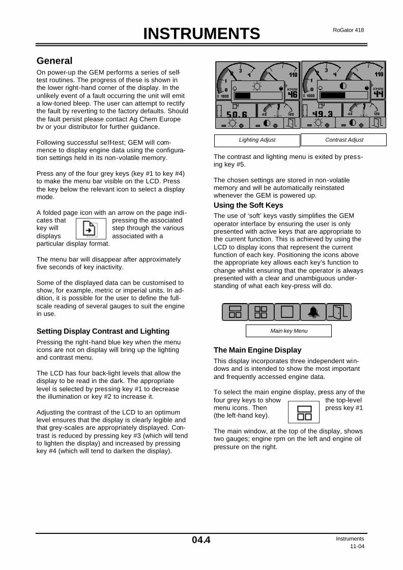
INSTRUMENTS
04.4 Instruments 11-04
RoGator 418
General On power-up the GEM performs a series of self-test routines. The progress of these is shown in the lower right-hand corner of the display. In the unlikely event of a fault occurring the unit will emit a low-toned bleep. The user can attempt to rectify the fault by reverting to the factory defaults. Should the fault persist please contact Ag Chem Europe bv or your distributor for further guidance. Following successful self-test; GEM will com-mence to display engine data using the configura-tion settings held in its non-volatile memory. Press any of the four grey keys (key #1 to key #4) to make the menu bar visible on the LCD. Press the key below the relevant icon to select a display mode. A folded page icon with an arrow on the page indi-cates that pressing the associated key will step through the various displays associated with a particular display format. The menu bar will disappear after approximately five seconds of key inactivity. Some of the displayed data can be customised to show, for example, metric or imperial units. In ad-dition, it is possible for the user to define the full-scale reading of several gauges to suit the engine in use.
Setting Display Contrast and Lighting Pressing the right-hand blue key when the menu icons are not on display will bring up the lighting and contrast menu. The LCD has four back-light levels that allow the display to be read in the dark. The appropriate level is selected by pressing key #1 to decrease the illumination or key #2 to increase it. Adjusting the contrast of the LCD to an optimum level ensures that the display is clearly legible and that grey-scales are appropriately displayed. Con-trast is reduced by pressing key #3 (which will tend to lighten the display) and increased by pressing key #4 (which will tend to darken the display).
The contrast and lighting menu is exited by press-ing key #5. The chosen settings are stored in non-volatile memory and will be automatically reinstated whenever the GEM is powered up.
Using the Soft Keys The use of ‘soft’ keys vastly simplifies the GEM operator interface by ensuring the user is only presented with active keys that are appropriate to the current function. This is achieved by using the LCD to display icons that represent the current function of each key. Positioning the icons above the appropriate key allows each key’s function to change whilst ensuring that the operator is always presented with a clear and unambiguous under-standing of what each key-press will do. The Main Engine Display This display incorporates three independent win-dows and is intended to show the most important and frequently accessed engine data. To select the main engine display, press any of the four grey keys to show the top-level menu icons. Then press key #1 (the left-hand key). The main window, at the top of the display, shows two gauges; engine rpm on the left and engine oil pressure on the right.
Lighting Adjust Contrast Adjust
Main key Menu

INSTRUMENTS
04.5 Instruments 11-04
RoGator 418
The window at the bottom-right of the display shows the coolant temperature.
Engine Hours Total engine hours received from engine. Trip Engine Hours Engine hours since last reset. Calculated from Total Engine hours. The Quad Display This display gives the user quick access to three screens, each displaying four gauges. The first screen shows four digital gauges, whilst the sec-ond and third screens each show four analogue gauges. Example displays are shown below. To select the quad display, press any of the four grey keys to show the top-level menu icons and then press key #2.
The screens are displayed sequentially in re-sponse to repeated presses of key #2. Using the adjust mode, each individual gauge displayed on the screens can be configured by the user to show a different engine parameter selected from an extensive list. The adjust mode is entered by pressing key #5 when the GEM is running in quad display mode and the menu is visible (if the menu isn’t visible, simply press any of the grey keys to make it re-appear). In adjust mode, the menu will appear as shown below: Pressing key #1 will cycle the top-left display through all available engine parameters, key #2 will cycle the top-right display etc. The adjust mode is exited by pressing key #5.
Quad 1
Quad 2
Quad 3
Quad 4
Main Screen
Representative view of first screen, showing four digital
gauges.
Representative view of second and third screens showing four
analogue gauges.
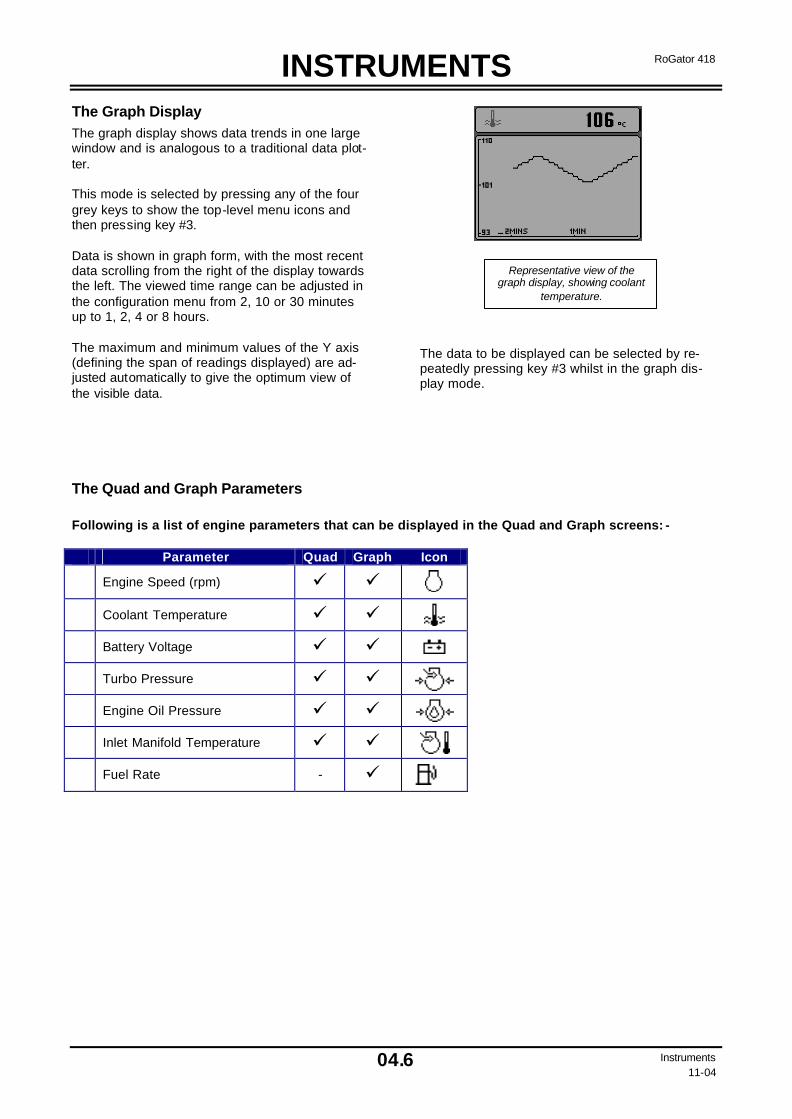
INSTRUMENTS
04.6 Instruments 11-04
RoGator 418
The Graph Display The graph display shows data trends in one large window and is analogous to a traditional data plot-ter. This mode is selected by pressing any of the four grey keys to show the top-level menu icons and then pressing key #3. Data is shown in graph form, with the most recent data scrolling from the right of the display towards the left. The viewed time range can be adjusted in the configuration menu from 2, 10 or 30 minutes up to 1, 2, 4 or 8 hours. The maximum and minimum values of the Y axis (defining the span of readings displayed) are ad-justed automatically to give the optimum view of the visible data.
The data to be displayed can be selected by re-peatedly pressing key #3 whilst in the graph dis-play mode.
The Quad and Graph Parameters Following is a list of engine parameters that can be displayed in the Quad and Graph screens: - Parameter Quad Graph Icon
Engine Speed (rpm) ü ü
Coolant Temperature ü ü
Battery Voltage ü ü
Turbo Pressure ü ü
Engine Oil Pressure ü ü
Inlet Manifold Temperature ü ü
Fuel Rate - ü
Representative view of the graph display, showing coolant
temperature.

INSTRUMENTS
04.7 Instruments 11-04
RoGator 418
The Alarm Display Screen The GEM recognises alarm messages received from the engine via the data link. When a new alarm is received the GEM will start to beep and a flashing pop-up window will appear with the latest alarm details. Pressing any key will display the alarm list screen which contains details of all previous alarms. Those that have already been acknowledged are shown as black text on a grey background. New alarms, that have not yet been acknowledged, are shown as highlighted grey text on a black back-ground. If engine hour’s data is available, the list will also indicate the engine hours when the alarm message was first received. When first entering the alarm page the list will automatically go to the most recent alarm re-ceived. If the list is longer than the screen size, the alarm list can be scrolled up and down using keys #1 and #2. The screen cannot be exited until all alarms have been acknowledged by pressing key #3. Alarm messages will be automatically cleared from the list if no longer received.
The alarm list screen can be viewed, at any time, by pressing key #4.
Pop-up Messages and Warnings In the configuration menu, the user can set the engine service interval in hours. When the GEM determines that an engine service is due, it will display a “SERVICE REQUIRED” message over-laying the start-up screen which appears for seven seconds following power-up. Should the GEM not detect valid engine data, a flashing pop-up window will appear displaying a “Communications Failure” icon denoting this fault condition. Once engine data transmissions have been detected the pop-up window will disappear and normal data display will continue.
A representative alarm pop-up message, showing low engine
oil pressure.
The alarm list screen, showing unacknowledged alarm condi-
tions.
The alarm list screen, showing that alarm conditions have been acknowledged. Note that the exit key (key #5) has now been activated.
The communications failure icon

INSTRUMENTS
04.8 Instruments 11-04
RoGator 418
Configuration The configuration mode allows the user to set various operating parameters and modes of the GEM. These include such choices as imperial or metric units, scale limits for the speedometer gauges, engine service interval etc. The configuration menu is entered by pressing and holding key #5 (the blue key) for at least 3 seconds when the GEM is in its normal operating mode. The top-level configuration menu will be displayed on the LCD, as shown below. Keys #1 and #2 allow the operator to move up and down the menu whilst key #4 enters the high-lighted menu item. Key #5 exits the configuration menu and saves all configuration data into non-volatile memory. The SETTINGS sub-menu allows the GEM to be configured according to the user’s preferences whilst SYSTEM accesses maintenance and low-level system configuration settings.
Selecting UNITS from the SET-TINGS sub-menu gives access to five parameters which can be displayed in units selected from a list. Use the up and down keys (key #1 and key #2) to select the required parame-ter, then press key #4 to cycle through the permitted units of measurement. Pressing key #5 returns the user to the main SET-TINGS menu.
The LANGUAGE sub-menu allows the user to select which language GEM uses to display mes-sages and prompts. Use the up and down keys (key #1 and key #2) to high-light the required language and then press key #4 to select it. Pressing key #5 returns the user to the main SETTINGS menu. BLEEP selects whether each key press is ac-knowledged with an audible bleep. Note that, even with BLEEP switched off, the audible alarm will still sound if an alarm condition occurs. The DISPLAY sub-menu allows the user to define the maximum rpm shown on the tachometer, the maximum speed shown on the speedometer and the speed with which the dis-play scrolls when using GEM in the graph display mode. SERVICE allows the user to set the engine service interval so that the GEM can, on power-up, remind the operator when a ser-vice becomes due. DEMO, the first item on the SYSTEM menu, allows the GEM to run in a demonstration mode, showing its capabilities even if not connected to a valid engine data stream. There are three different demo modes. DEMO 1 has speed data simulated by the GEM, DEMO 2 does not generate simulated speed data, and DEMO 3 simulates various alarm conditions. For normal use, the demo mode must be switched to OFF. RESTORE DEFAULTS allows the user to reset all configuration data to the factory defaults. The user may select either metric or imperial units: the de-fault values for each are shown below.
Setting Metric Imperial Language English Max RPM 4000 Graph range 2 mins Pressure kPa PSI Volume L Gal Temperature ºC ºF
The top-level configuration menu and SETTINGS and SYSTEM sub-menus.
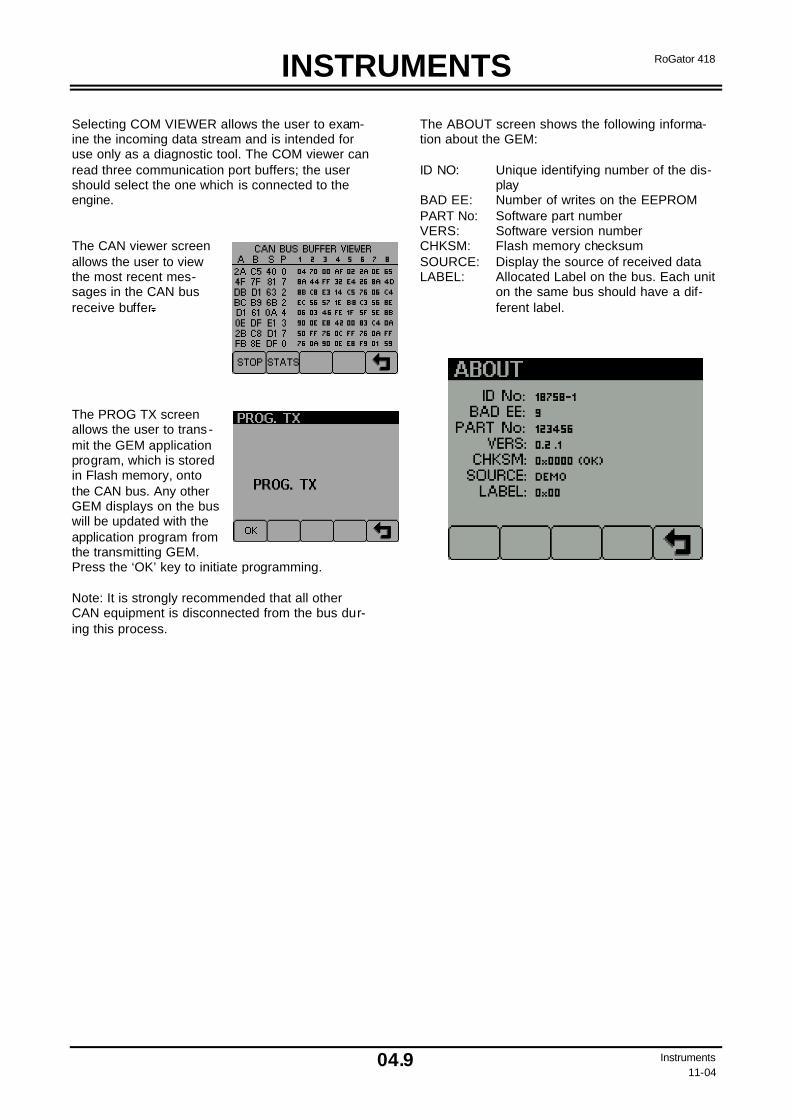
INSTRUMENTS
04.9 Instruments 11-04
RoGator 418
Selecting COM VIEWER allows the user to exam-ine the incoming data stream and is intended for use only as a diagnostic tool. The COM viewer can read three communication port buffers; the user should select the one which is connected to the engine. The CAN viewer screen allows the user to view the most recent mes-sages in the CAN bus receive buffer. The PROG TX screen allows the user to trans-mit the GEM application program, which is stored in Flash memory, onto the CAN bus. Any other GEM displays on the bus will be updated with the application program from the transmitting GEM. Press the ‘OK’ key to initiate programming. Note: It is strongly recommended that all other CAN equipment is disconnected from the bus dur-ing this process.
The ABOUT screen shows the following informa-tion about the GEM: ID NO: Unique identifying number of the dis-
play BAD EE: Number of writes on the EEPROM PART No: Software part number VERS: Software version number CHKSM: Flash memory checksum SOURCE: Display the source of received data LABEL: Allocated Label on the bus. Each unit
on the same bus should have a dif-ferent label.

OPERATION
05.1 Operation
11-04
RoGator 418
Before Starting the Vehicle En-gine • Go around the vehicle and inspect for any de-
fects.
• Check the engine oil level.
• Check the engine coolant level. The coolant must reach the base of the cap.
• Check the oil level in the hydraulic oil tank. The oil must be visible in the sight glass. Add oil if necessary, but do not over fill.
• Check all the items under “Every 10 hours or daily” in the Service Manual.
• Adjust the seat so that all instruments and con-trols are accessible.
• Fasten the seat belt.
• Release the parking brake of the vehicle.
CAUTION!
DO NOT run the starter more than 30 seconds. Let the starter cool for 2 minutes before engaging the star-ter again.
IMPORTANT: Check the instruments fre-quently when operating the RoGator.
OPERATION
05.2 Operation
11-04
RoGator 418
Starting the Engine
DANGER!
Caution: Take care to avoid (fatal) injuries when starting the vehicle. Do not start the engine if a short will be caused due to inter-changed starter leads. The engine starts properly if the circuit is properly connected. NEVER start the vehicle when standing on the ground. Only start the vehicle from the seat when the vehicle is in neutral and the parking brake ap-plied.
DANGER!
Caution: Ensure for sufficient ven-tilation when starting the vehicle in an enclosed space. EXHAUST GASES are POISONOUS. If the engine is being started with jump-ing cables, ensure that no sparks are produced. BATTERY GAS is EXPLOSIVE.
Turn the key to “ON”. Continue to turn the key to “START” and hold it there until the engine is run-ning. The engine must start within 30 seconds. DO NOT let the starter run longer than 30 seconds. Al-low the starter one minute to cool before repeating a start. Let the engine run with a small load until the temperature gauge indicates operating temperature.
Restarting a Stalled Engine Start a stalled engine IMMEDIATELY in order to prevent a marked rise in temperature.
Continue working or allow the engine to run at 1000 – 1200 rpm for two minutes before stopping the en-gine.
Starting at Low Temperatures (See the engine manual.)
Hydraulic System – Operation at Low Temperatures
Ambient Temperature
Warm-up Procedure
5ºC – and higher
Allow the engine to run about 10 minutes at a speed of 1500 rpm.
-1ºC to 5ºC Allow the engine to run about 20 minutes at a speed of 1500 rpm.
Below -1ºC Allow the engine to run for 30 minutes at a speed of 800 rpm or lower. Observe the boost pressure. The minimum boost pressure should be 20 bar and remain constant. If the pressure is below 20 bar or fluctuates, stop the engine. The oil must be heated or changed. Fill with oil, type ISO VG 46.
ATTENTION: An incorrect starting procedure dur-ing low temperatures can lead to heavy damage to the hydraulic system. Follow the table below to perform the cold start properly. Observe the boost pressure readings on the screen. The minimum boost pressure should be 20 bar. Stop engine if the boost pressure is lower than the minimum value or if the reading fluctuates. The engine speed should be less than 1500 rpm.
NOTE: The filter warning light may illuminate. The light will extinguish when the machine reaches the operating temperature of 21ºC.

OPERATION
05.3 Operation
11-04
RoGator 418
Driving the RoGator
CAUTION!
Caution: The RoGator is a hydro-statically driven vehicle. Drive the machine only after having read and understood this manual.
Driving the RoGator with the “Field / Road” Switch in the “Road” Position 1. Release the parking brake. Be careful the lad-
der will be tilted.
2. Select first gear.
3. Slowly move the traction control lever from neu-tral to forward or reverse. The machine will re-main stationary until the accelerator is actu-ated. The vehicle speed depends on how far the traction control lever is moved in a certain direc-tion and how far the accelerator is operated.
4. Select the correct gear for the desired accelera-tion and also the desired engine speed.
5. To stop the vehicle, release the accelerator and, if necessary, brake slightly with the service brake. The traction control lever can remain in its position.
Driving the RoGator with the “Field / Road” Switch in the “Field” Position 1. Release the parking brake. Be careful the lad-
der will also be tilted.
2. Select the desired RPM.
3. Select first gear.
4. Slowly move the traction control lever from neu-tral to forward or reverse. The vehicle speed de-pends on how far the traction control lever is moved in a certain direction.
5. Select the correct gear for the desired accelera-tion and also the desired engine speed.
6. To stop the vehicle, move the traction control lever to neutral from forward or reverse, if nec-essary, brake slightly with the service brake. This reduces the output of the traction pumps; if the brake pedal is depressed further the service brakes are applied.
Economic Driving Observe the screen indicating the vehicle speed regularly. This is the most effect method of driving.
Driving at a pressure over 245 bar is not economic.
Driving at a pressure less than 245 bar is economic.
WARNING!
Caution: Select a low speed range before driving up a steep slope. Non-observance of this warning can lead to injuries and death.
Speed Ranges: • Speed range 1: 0 – 20 km/h (0 – 12.5 mph)
• Speed range 2: 0 – 30 km/h (0 – 19 mph)
• Speed range 3: 0 – 40 km/h (0 – 25 mph)
WARNING!
Caution: Do not exceed the rec-ommended tyre speed. This speed can be lower than the aforementioned speed. Exceed-ing the speed limit can lead to personal injuries or death.
WARNING!
Caution: Ensure that the tyres when replaced are of the same or higher load/speed rating of those mounted ex works.
NOTE: If the RoGator loses speed when driving uphill, do not use the traction control lever to increase speed. Instead, move the traction control lever towards neutral so that the en-gine speed rises and the vehicle speed is sta-bilised, or select a different gear.

OPERATION
05.4 Operation
11-04
RoGator 418
4-Wheel Steering
Operation The 4-wheel steering can only be used if the "field / road” switch is set to “field”. Subsequently, the de-sired type of steering is selected with the switch for 4-wheel steering and the foot switch.
Switch for 4-Wheel Steering When the aforementioned switch is set to “field”, it is possible to select three positions with the switch for the 4-wheel steering:
• automatic
• manual
• All-wheel steering off.
Automatic This is the work position for the all-wheel steering. When the switch is set to this position, it is possi-ble to select all-wheel steering with the foot switch. The indicator light on the dashboard indicates if the machine is in all-wheel steering or two-wheel steer-ing. If the light for two-wheel steering is on, all-wheel steering can be selected by pressing the foot switch. The indicator light for two wheel steering on the dashboard extinguishes, and the light for all-wheel steering illuminates. When the front axle goes through the centre position and the indicator light for middle position front axle illuminates, the all-wheel steering is effective and the rear wheels steer along with the front wheels. To deselect the all-wheel steering, the foot switch must be de-pressed again. The indicator light for all wheel steer-ing on the dashboard extinguishes and the indicator light for two wheel steering illuminates. When the rear axle goes through the centre position and the indicator light for middle position front axle goes on, the all-wheel steering is deselected and the rear axle remains in the centre position.
CAUTION!
Caution: Use the 4-wheel steering only for turning on the headlands. Switch off the 4-wheel steering when driving in the tramlines. Driv-ing in the tramlines with the 4-wheel steering switched on can cause an unstable drive of the ma-chine and excessive boom motion.
Manual This is the calibration position for the all-wheel steering. If the switch is in this position, it is always possible to select all-wheel steering by depressing the foot switch. The indicator light for all-wheel steering comes on. The rear wheel now steers along with the front wheels, independent of the position of the front wheels. In this way it is possible to ensure that the rear wheels are aligned with the front wheels again, in case the adjustment of the steering sensors is no longer correct.
4-Wheel Steering Off In this position the 4-wheel steering can no longer be used, and depressing the foot switch has no ef-fect.
Driving on Public Roads To drive on public roads set the field / road switch to the "road" position. This is an additional safety fac-tor to prevent rear axle steering.
If all-wheel steering is selected and the field / road switch is set to the "road" position, all-wheel steer-ing is disabled as soon as the rear axle reaches the centre position.
Turning Machine Off with Rear Wheels Steered If the machine is shut down with the rear wheels steered, problems may occur when the machine is driven again. It is possible that the rear wheels do not steer after starting the machine. In this case the switch for all-wheel steering must be set to the “manual” position. Depress the foot switch if the indicator light for all-wheel steering does not come on. Then turn the steering wheel until the indicator light for all-wheel steering comes on. The rear wheels are now centred. Now select either “auto-matic” or “all-wheel steering off” with the all-wheel steering switch. It is better to turn the all-wheel steering off before shutting the machine off.
CAUTION!
Caution: Before shutting the ma-chine off, the rear wheels must be in the centre position and the all-wheel steering must be turned off.

OPERATION
05.5 Operation
11-04
RoGator 418
Front Axle Suspension (Option) The front axle suspension allows a comfortable and smooth driving of the machine, on public roads and in the field.
Automatic Position When the orange suspension switch is operated downwards, the suspension goes to the automatic position. In the automatic position the shock ab-sorbers always return to the centre position, after having been extended or retracted. The automatic position must be reselected whenever the machine is started.
Manual Position In the manual position the shock absorbers can be extended and retracted manually with the manual mode switch. This switch is located beside the or-ange switch. When the machine is started, the suspension is in the manual position. When the suspension is in the automatic position, it will go into the manual position automatically as soon as the manual mode switch is toggled up or down. Bet-ter access to the machine can be gained by using the manual mode switch toggled down to drop the suspension to its minimum value.
WARNING!
Caution: The machine must be re-set to the automatic position each time it is started.
Hydraulic Skid Regulator (op-tion) The skid regulator can be used in difficult driving conditions, wetness and very steep slopes and when slip develops. Use the skid regulator only if necessary; do not use the skid regulator longer as necessary.
Switching the skid regulator on/off Switch the skid regulator on and off with the switch (switch 10 see P03.5) on the instrumentpanel. When the skid regulator is activated the green lamp (Lamp 23 see P03.5) on instrument panel lights up. To deactivate the skid regulator push the switch to the Off side, the green lamp will go out.
NOTE: To use the skid regulator the field/road switch must be in the position field. The skid regulator functions only in the first gear.
WARNING!
Caution: Use the skid regulator only when necessary.
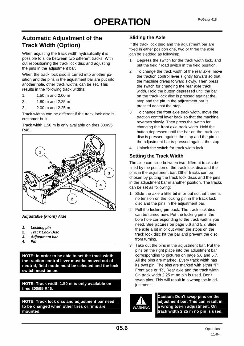
OPERATION
05.6 Operation
11-04
RoGator 418
Automatic Adjustment of the Track Width (Option) When adjusting the track width hydraulically it is possible to slide between two different tracks. With out repositioning the track lock disc and adjusting the pins in the adjustment bar.
When the track lock disc is turned into another po-sition and the pins in the adjustment bar are put into another hole, other track widths can be set. This results in the following track widths:
1. 1.50 m and 2.00 m
2. 1.80 m and 2.25 m
3. 2.00 m and 2.25 m
Track widths can be different if the track lock disc is customer built.
Track width 1.50 m is only available on tires 300/95 R46.
Adjustable (Front) Axle
1. Locking pin 2. Track Lock Disc 3. Adjustment bar 4. Pin
NOTE: In order to be able to set the track width, the traction control lever must be moved out of neutral, field mode must be selected and the lock switch must be on.
NOTE: Track width 1.50 m is only available on tires 300/95 R46.
NOTE: Track lock disc and adjustment bar need to be changed when other tires or rims are mounted.
Sliding the Axle If the track lock disc and the adjustment bar are fixed in either position one, two or three the axle can be sledded as following:
1. Depress the switch for the track width lock, and put the field / road switch in the field position.
2. To change the track width of the rear axle, move the traction control lever slightly forward so that the machine drives forward slowly. Then press the switch for changing the rear axle track width. Hold the button depressed until the bar on the track lock disc is pressed against the stop and the pin in the adjustment bar is pressed against the stop.
3. To change the front axle track width, move the traction control lever back so that the machine reverses slowly. Then press the switch for changing the front axle track width. Hold the button depressed until the bar on the track lock disc is pressed against the stop and the pin in the adjustment bar is pressed against the stop.
4. Unlock the switch for track width lock.
Setting the Track Width The axle can slide between two different tracks de-fined by the position of the track lock disc and the pins in the adjustment bar. Other tracks can be chosen by putting the track lock discs and the pins in the adjustment bar in another position. The tracks can be set as following:
1. Slide the axle a little bit in or out so that there is no tension on the locking pin in the track lock disc and the pins in the adjustment bar.
2. Pull the locking pin back. The track lock disc can be turned now. Put the locking pin in the bore hole corresponding to the track widths you need. See pictures on page 5.6 and 5.7. Slide the axle a bit in or out when the stops on the track lock disc hit the bar and prevent the disc from turning.
3. Take out the pins in the adjustment bar. Put the pins on the right place into the adjustment bar corresponding to pictures on page 5.6 and 5.7. All the pins are marked. Every track width has its own pin. The pins are marked with either “F”, Front axle or “R”, Rear axle and the track width. On track width 2.25 m no pin is used. Don’t swap pins. This will result in a wrong toe-in ad-justment.
WARNING!
Caution: Don’t swap pins on the adjustment bar. This can result in a wrong toe-in adjustment. On track width 2.25 m no pin is used.
1
2
3
4

OPERATION
05.7 Operation
11-04
RoGator 418
F 1,50
F 2,00
Position Track lock disc
Track width 1,50 m – 2,00 m (Front axle)
Track width 1,80 m – 2,25 m (Front axle)
F 1,80
No Pin
Position Track lock disc

OPERATION
05.8 Operation
11-04
RoGator 418
Track width 2,00 m – 2,25 m (Front axle)
Never drive the vehicle on the road on a track width of 2.25 m.
WARNING!
Caution: It is not allowed to drive the vehicle at full speed on the road on a track of 2.25 m.
Maintenance on the sliding axle The axle needs to be slided once a week in the sea-son to prevent the axle tubes from getting stuck. Clean the slide axle once a week or every 50 hours and lubricate the sliding surfaces with grease.
Clean and lubricate the sliding surfaces before stor-ing the machine in the winter period. Slide the axle fully out when storing.
NOTE: Keep the sliding surfaces clean and greased to prevent the axle tubes from getting stuck.
F 2,00 (2,25) No Pin
Position Track lock disc
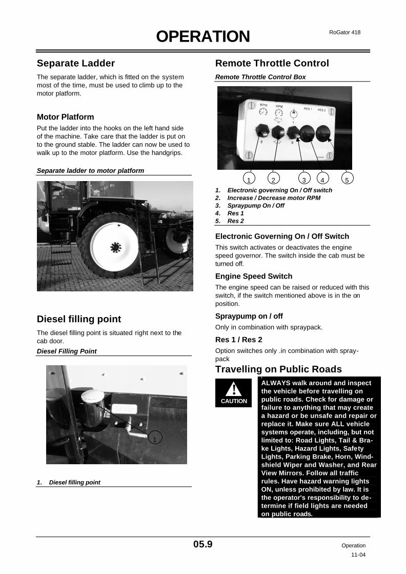
OPERATION
05.9 Operation
11-04
RoGator 418
Separate Ladder The separate ladder, which is fitted on the system most of the time, must be used to climb up to the motor platform.
Motor Platform Put the ladder into the hooks on the left hand side of the machine. Take care that the ladder is put on to the ground stable. The ladder can now be used to walk up to the motor platform. Use the handgrips.
Separate ladder to motor platform
Diesel filling point The diesel filling point is situated right next to the cab door.
Diesel Filling Point
1. Diesel filling point
Remote Throttle Control Remote Throttle Control Box
1. Electronic governing On / Off switch 2. Increase / Decrease motor RPM 3. Spraypump On / Off 4. Res 1 5. Res 2
Electronic Governing On / Off Switch This switch activates or deactivates the engine speed governor. The switch inside the cab must be turned off.
Engine Speed Switch The engine speed can be raised or reduced with this switch, if the switch mentioned above is in the on position.
Spraypump on / off Only in combination with spraypack.
Res 1 / Res 2 Option switches only .in combination with spray-pack
Travelling on Public Roads
CAUTION!
ALWAYS walk around and inspect the vehicle before travelling on public roads. Check for damage or failure to anything that may create a hazard or be unsafe and repair or replace it. Make sure ALL vehicle systems operate, including, but not limited to: Road Lights, Tail & Bra-ke Lights, Hazard Lights, Safety Lights, Parking Brake, Horn, Wind-shield Wiper and Washer, and Rear View Mirrors. Follow all traffic rules. Have hazard warning lights ON, unless prohibited by law. It is the operator's responsibility to de-termine if field lights are needed on public roads.
1
1 2 3 5 4

MAINTENANCE
06.1 Maintenance 11-04
RoGator 418
Maintenance Introduction
IMPORTANT: Perform Maintenance proce-dures at regularly scheduled intervals. Failure to perform regularly scheduled maintenance will result in damage to the RoGator compo-nents or engine. The maintenance schedule is a recommended guide for correct maintenance of the RoGator vehicle.
DO NOT change the schedule unless you increase the frequency of service when operating the Ro-Gator in very hot, cold, dusty or corrosive condi-tions. Use the hour meter as a guide for maintenance intervals. The maintenance intervals can be shown in both operating hours and time. Example: 10 Hours or Every Day. Use the interval (operating hours or time) that comes first.
Lubricants and Fluids
IMPORTANT: Capacities listed are APPROXI-MATE. CHECK fluid levels after filling, by using the indicators.
IDENTIFICATION RECOMMENDED CAPACITY HYDRAULIC SYSTEM ISO VG 46 200 L ENGINE COOLANT Caterpillar diesel engine antifreeze /coolant. Or commer-
cial heavy -duty coolant / antifreeze that meets ASTM D4985 or ASTM D5345
35 L
ENGINE OIL SAE 15W-40 API Class CE-CD/SF engine oil 13.1 L GREASE FITTINGS Hi Temperature Moly-Lithium Base Grease NLGI #2 As Required SLIDING SURFACE TRACK ADJUSMENT (OPTION)
PTFE Pen lube SS 105 acc. CEC-L-33-T-82 As Required
Lubricant Filling Reminders Use only high quality lubricants. Low quality lubricants reduce the service life of the vehicle and can cause component failures. When a lubricant is specified, do not use a differ-ent lubricant.
Do not add a lubricant unless it is the same type and grade as the lubricant already in use. If the grade is not known or not available, replace the lubricant with new lubricant. Keep all lubricants in clean containers and in an area that has protection from dust, dirt, water and other contamination.

MAINTENANCE
06.2 Maintenance 11-04
RoGator 418
Maintenance Symbols
Inspect or check
Elapsed operating hours
Grease lubrication, every 50 hours
Oil lubrication, every 50 hours
Service interval reminder
Pressurized
Drain / empty
Engine oil
Engine oil level
Engine oil filter
Engine coolant level
Hydraulic oil
Hydraulic oil level
Hydraulic oil filter
Battery
Fuel filter
Air cleaner
Tyre pressure

MAINTENANCE
06.3 Maintenance 11-04
RoGator 418
Maintenance Schedule
Service Item
First 100
Hours
Daily 50 Hours
100 Hours
250 Hours
500 Hours
1000 Hours
Annually
1. Check the tyre pressure X X
2. Check the labels X X
3. Check the coolant X X
4. Check the fuel - water separation X X
5. Check the engine oil level X X
6. Check the hydraulic oil level X X
7. Remove the water in the air tanks X X
8. Lubricate the axle stubs X X
9. Check the battery leads X X
10. Check the hydraulic pipes & hoses X X
11. Check the compressed air hoses X X
12. Check the V-belts X X
13. Clean the combined cooler X X
14. Lubricate the steering ball joints X X
15. Clean and lubricate the sliding axle X X
16. Check the cab mountings X X
17. Replace the engine oil and filter X X
18. Replace the fuel filters X X
19. Remove plug at bottom of fuel tank and remove sediment X X
20. Replace the leakage oil filter X X
21. Replace the suction and return line filter X X 22. Tighten the wheel lugs and the wheel motor
screws X X
23. Replace the hydraulic oil X
24. Replace the air cleaner elements X 25. Drain and replace the coolant and the
SCA's X

MAINTENANCE
06.4 Maintenance 11-04
RoGator 418
ROGATOR 418
418
ROGATOR
418
ROGATOR 418
00
1
1 1
3 4 5
6
7
8 8
9
12 13 17 18
18
20 21
21
22
23
24
25
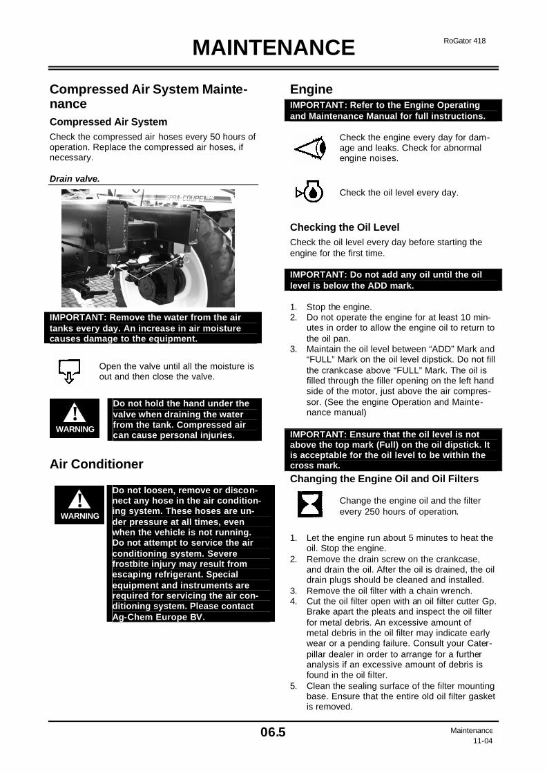
MAINTENANCE
06.5 Maintenance 11-04
RoGator 418
Compressed Air System Mainte-nance Compressed Air System Check the compressed air hoses every 50 hours of operation. Replace the compressed air hoses, if necessary. Drain valve. IMPORTANT: Remove the water from the air tanks every day. An increase in air moisture causes damage to the equipment.
Open the valve until all the moisture is out and then close the valve.
WARNING!
Do not hold the hand under the valve when draining the water from the tank. Compressed air can cause personal injuries.
Air Conditioner
WARNING!
Do not loosen, remove or discon-nect any hose in the air condition-ing system. These hoses are un-der pressure at all times, even when the vehicle is not running. Do not attempt to service the air conditioning system. Severe frostbite injury may result from escaping refrigerant. Special equipment and instruments are required for servicing the air con-ditioning system. Please contact Ag-Chem Europe BV.
Engine IMPORTANT: Refer to the Engine Operating and Maintenance Manual for full instructions.
Check the engine every day for dam-age and leaks. Check for abnormal engine noises.
Check the oil level every day.
Checking the Oil Level Check the oil level every day before starting the engine for the first time. IMPORTANT: Do not add any oil until the oil level is below the ADD mark. 1. Stop the engine. 2. Do not operate the engine for at least 10 min-
utes in order to allow the engine oil to return to the oil pan.
3. Maintain the oil level between “ADD” Mark and “FULL” Mark on the oil level dipstick. Do not fill the crankcase above “FULL” Mark. The oil is filled through the filler opening on the left hand side of the motor, just above the air compres-sor. (See the engine Operation and Mainte-nance manual)
IMPORTANT: Ensure that the oil level is not above the top mark (Full) on the oil dipstick. It is acceptable for the oil level to be within the cross mark.
Changing the Engine Oil and Oil Filters
Change the engine oil and the filter every 250 hours of operation.
1. Let the engine run about 5 minutes to heat the
oil. Stop the engine. 2. Remove the drain screw on the crankcase,
and drain the oil. After the oil is drained, the oil drain plugs should be cleaned and installed.
3. Remove the oil filter with a chain wrench. 4. Cut the oil filter open with an oil filter cutter Gp.
Brake apart the pleats and inspect the oil filter for metal debris. An excessive amount of metal debris in the oil filter may indicate early wear or a pending failure. Consult your Cater-pillar dealer in order to arrange for a further analysis if an excessive amount of debris is found in the oil filter.
5. Clean the sealing surface of the filter mounting base. Ensure that the entire old oil filter gasket is removed.
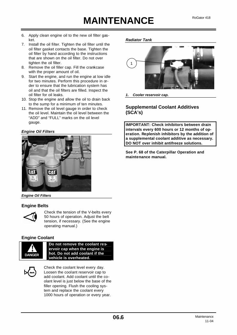
MAINTENANCE
06.6 Maintenance 11-04
RoGator 418
6. Apply clean engine oil to the new oil filter gas-ket.
7. Install the oil filter. Tighten the oil filter until the oil filter gasket contacts the base. Tighten the oil filter by hand according to the instructions that are shown on the oil filter. Do not over tighten the oil filter.
8. Remove the oil filler cap. Fill the crankcase with the proper amount of oil.
9. Start the engine, and run the engine at low idle for two minutes. Perform this procedure in or-der to ensure that the lubrication system has oil and that the oil filters are filled. Inspect the oil filter for oil leaks.
10. Stop the engine and allow the oil to drain back to the sump for a minimum of ten minutes.
11. Remove the oil level gauge in order to check the oil level. Maintain the oil level between the “ADD” and “FULL” marks on the oil level gauge.
Engine Oil Filters Engine Oil Filters
Engine Belts
Check the tension of the V-belts every 50 hours of operation. Adjust the belt tension, if necessary. (See the engine operating manual.)
Engine Coolant
DANGER!
Do not remove the coolant res-ervoir cap when the engine is hot. Do not add coolant if the vehicle is overheated.
Check the coolant level every day. Loosen the coolant reservoir cap to add coolant. Add coolant until the co-olant level is just below the base of the filler opening. Flush the cooling sys-tem and replace the coolant every 1000 hours of operation or every year.
Radiator Tank 1. Cooler reservoir cap.
Supplemental Coolant Additives (SCA’s)
IMPORTANT: Check inhibitors between drain intervals every 600 hours or 12 months of op-eration. Replenish inhibitors by the addition of a supplemental coolant additive as necessary. DO NOT over inhibit antifreeze solutions.
See P. 68 of the Caterpillar Operation and maintenance manual.
1

MAINTENANCE
06.7 Maintenance 11-04
RoGator 418
Air Cleaner Maintenance
Service the air cleaner at regular inter-vals for proper engine performance and long life.
Check the air cleaner condition indicator every day.
Check the rubber elbows and hose clamps on the air intake system every day.
Replace the air filter element with a new element after it was cleaned 6 times or if damaged.
Replace the air filter element with a new element every year.
Engine Air Cleaner Housing Air filter housing
Primary Filter Element To clean or replace the primary filter, first remove the cover at the front of the air cleaner. Then re-move the filter element carefully from the air cleaner. Primary Filter Primary Filter
IMPORTANT: Damage can occur to the primary filter if it is hit against a tyre or hard surface. To remove dust from the element, hit the base of the element carefully with the heel of your hand and turn the element while hit-ting. 1. Use compressed air to clean the element.
Direct the air through the element in the oppo-site direction of normal flow through the ele-ment.
2. Move the nozzle up and down while turning the element. Keep the nozzle a minimum of one inch from the surface. Do not use exces-sive air pressure to clean air filter elements. They can be damaged by excessive pressure.
3. After cleaning the element, place a bright light inside the filter element. Turn the element around the light and check for damage. If any cracks or holes are found, replace the ele-ment.
4. If gaskets are damaged or missing, replace the element.
5. If it is necessary, remove the inner filter ele-ment.
6. Install the filter element(s). Install the dust cup. Make sure it seals all the way around the air cleaner body. Reset the filter condition indicator to green.
7. Check all connections between the air cleaner and the engine. Make sure they are tight and leak free.
IMPORTANT: Remove the inner filter element only if it is to be replaced. Do not attempt to clean the inner filter. Always replace the inner air filter element
WARNING!
Chemical residue may be pre-sent in dirt on the filter ele-ments. Always wear protective gloves when servicing the filter elements.

MAINTENANCE
06.8 Maintenance 11-04
RoGator 418
Inner Filter Element
Replace the element annually. The inner filter element protects the engine if the primary filter element is damaged. It also protects the engine when the pri-mary filter element is being serviced.
IMPORTANT: Do not clean the inner filter element. It must be replaced with new filter element.
WARNING!
Chemical residue may be present on the filters. Always wear protective gloves when servicing the filter elements.
Fuel When fuelling the vehicle keep the fuel tank cap clean. Refer to the Engine Operation and Mainte-nance Manual for fuel additives.
WARNING!
Only use diesel fuel with the specification EN 590.
WARNING!
Add fuel only in an area that has a free movement of fresh air and no open flames or sparks. Never smoke when adding fuel. Always switch off the engine before refuelling.
Fuel Tank The diesel fuel tank has a capacity of 200 litres.
Remove the sediment from the bottom of the tank every 500 hours of operation and let a small amount of fuel flow into a container. This will remove dirt and water from the bottom of the fuel tank
Fuel Tank
1. Fuel tank 2. Drain plug
Fuel Storage Long storage of fuel can cause gumming to form. Gumming will cause fuel filters and other parts of the fuel system to clog. Keep dirt, water and for-eign material out of the fuel. Do not keep any fuel for a long period of time.
IMPORTANT: Water can damage the fuel injec-tion system on the engine. Keep the fuel tank and storage tanks full to prevent condensation. Always use high quality fuel. Remove and properly dispose of old fuel from tanks after long storage periods.
Fuel Filter
Replace the fuel filter every 500 hours of operation or if the engine perform-ance is low. Loosen the drain plug at the bottom of the fuel filter every day. Drain the water until fuel begins to flow out.
Replace the Fuel Filters
1. Clean the outside of the fuel filter assembly. Open drain valve (3) and drain the fuel and water from fuel filter (2) into a suitable con-tainer.
2. Hold fuel filter (2) and rotate quick release collar (1) anti clockwise. Remove quick re-lease collar (1). The used element should be removed and discarded.
3. Ensure that the fuel filter base is clean. Push a new fuel filter fully into the fuel filter base.
4. Hold the fuel filter in place. Fit locking ring (1) into position. Rotate the locking ring clockwise in order to fasten the fuel filter to the fuel filter base. Prime the fuel system.
Fuel Filter 1. Cap 2. Fuel filter base 3. Quick release collar 4. Fuel filter 5. Drain valve for fuel filter
1
2
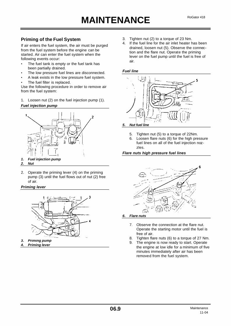
MAINTENANCE
06.9 Maintenance 11-04
RoGator 418
Priming of the Fuel System If air enters the fuel system, the air must be purged from the fuel system before the engine can be started. Air can enter the fuel system when the following events occur: • The fuel tank is empty or the fuel tank has
been partially drained. • The low pressure fuel lines are disconnected. • A leak exists in the low pressure fuel system. • The fuel filter is replaced. Use the following procedure in order to remove air from the fuel system: 1. Loosen nut (2) on the fuel injection pump (1). Fuel injection pump 1. Fuel injection pump 2. Nut 2. Operate the priming lever (4) on the priming
pump (3) until the fuel flows out of nut (2) free of air.
Priming lever 3. Priming pump 4. Priming lever
3. Tighten nut (2) to a torque of 23 Nm. 4. If the fuel line for the air inlet heater has been
drained, loosen nut (5). Observe the connec-tion and the flare nut. Operate the priming lever on the fuel pump until the fuel is free of air.
Fuel line 5. Nut fuel line
5. Tighten nut (5) to a torque of 22Nm. 6. Loosen flare nuts (6) for the high pressure
fuel lines on all of the fuel injection noz-zles.
Flare nuts high pressure fuel lines 6. Flare nuts
7. Observe the connection at the flare nut. Operate the starting motor until the fuel is free of air.
8. Tighten flare nuts (6) to a torque of 27 Nm. 9. The engine is now ready to start. Operate
the engine at low idle for a minimum of five minutes immediately after air has been removed from the fuel system.
MAINTENANCE
06.10 Maintenance 11-04
RoGator 418
Tyre Maintenance
Check the tyres for correct pressure and damage every day.
WARNING!
Wear eye protection and stand away from the tyre while adding air to prevent possible personal injury from blow-outs, etc.
WARNING!
Never exceed the tyre manufac-turer's maximum recommended inflation pressure. Do not ex-ceed vehicle speeds and loads shown on the Tyre Air Pressure Chart.
Protect the tyres from long periods of contact with fuel, grease oil and chemicals. Some chemicals can damage rubber. Wash the tyres every day after the application of chemicals. Air temperature can have a large effect on the tyre pressure. At low temperatures tyre pressure drops. At high tem-peratures tyre pressure rises.
Tyre Mounting
WARNING!
The driver / operator must be aware that the tyres which may be mounted on the rims have a lower approved load than the factory tyres. Personal injury or death can result if the driver does not observe this and ex-ceeds either the load or speed of the changed tyres of a lesser quality.
WARNING!
Failure to follow the correct in-structions when installing a tyre on a wheel or rim can produce an explosion that can cause personal injury or death. DO NOT attempt to install a tyre unless you have the correct equipment and are trained and qualified to perform the proce-dures safely. Have all tyre repair or replacements performed by a trained and qualified tyre service centre.
CAUTION!
If the tyres must be replaced, contact Ag-Chem Europe b.v. The specifications of the new tyres must be EQUAL or HIG-HER than the specifications and approved load of the old tyres. The wrong selection of tyres and/or the use of different types of tyres can result in a loss of control over the vehicle while driving, which can lead to acci-dents. The installation of: Used and new tyres, bias-ply and ra-dial-ply tyres, and tyres with different diameters or load ra-dius can lead to damage.
IMPORTANT: The air in the tyres may be re-moved in order to be able to ship the vehicle. Check the tyres and inflate them according to the values specified in the above chart. IMPORTANT: Certain tyres require a reduction of the admissible maximum speed and load. It is the responsibility of the driver to weigh the vehicle and the product transported. If help is required in determining the maximum product quantity, contact Ag- Chem Europe BV .

MAINTENANCE
06.11 Maintenance 11-04
RoGator 418
Tyre Pressure Chart Kleber Super 3 300/95 R46 TL 147A8 Speed = 100%
Width Diameter 1.8 2.2 2.6 2.8 3.0 3.2 3.6 Km/h
2030 2260 2500 2610 2730 2840 3080 40 2160 2420 2670 2780 2920 3030 3280 30 2360 2630 2900 3040 3180 3320 3590 15
309 mm 1724 mm
2420 2700 2980 3120 3260 3410 3690 10 Kleber Traker 420/85 R38 TL 144 A8 Speed = 96%
Width Diameter 1.0 1.2 1.3 1.4 1.6 2.1 Km/h
1980 2180 2280 2380 2575 50 2160 2370 2480 2590 2800 40 2310 2540 2650 2770 3000 30
445 mm 1665 mm
2790 3050 3180 3300 3560 4200 10 Michelin XM 108 540/65 R38TL 147A8 Speed = 98%
Width Diameter 0.6 0.8 1 1.1 1.2 1.4 1.5 Km/h
1880 2080 2280 2310 2480 2680 50 1880 2180 2480 2510 2780 3080 40 2010 2330 2650 2690 2970 3290 30
520 mm 1683 mm
2440 2840 3230 3270 3630 4020 3980 10 Wheel Maintenance IMPORTANT: DURING BREAK-IN Period. Loosen each wheel during the first 50 hours of
operation according following procedure: 1. 1/4 turn, 2. Tighten to a torque of 250 Nm, 3. Tighten each wheel mounting bolt accord-
ing to wheel bolt tightening sequence pic-ture,
4. Tighten to a torque of500 Nm, 5. Retighten every 500 hours of operation.
Removing the Wheels 1. Put the vehicle on a hard, level surface. Place
blocks behind the wheels that are not being removed.
2. Lift the vehicle and support it with safety stands. Use safety stands that will support the weight of the vehicle.
WARNING!
Never support the vehicle only with a jack or supports that can crumble. Injury or death can result.
3. Remove the wheel nut and the lock washer,
using metric tools. 4. Remove the wheel from the axle with a second
person.
CAUTION!
Use the proper equipment when removing the wheel from the axle. Injury or death can result.
Installing the Wheels 1. The wheel mounting surfaces of the wheel
motor, the wheel disc and the back of the wheel nut must be true and clean.
2. Position the wheel over the wheel motor, tak-ing the position of the wheel nut into consid-eration.
3. Tighten the wheel nut by hand. First tighten opposite wheel nuts to 250 Nm and then to 500 Nm.
Wheel Bolt Tightening Sequence
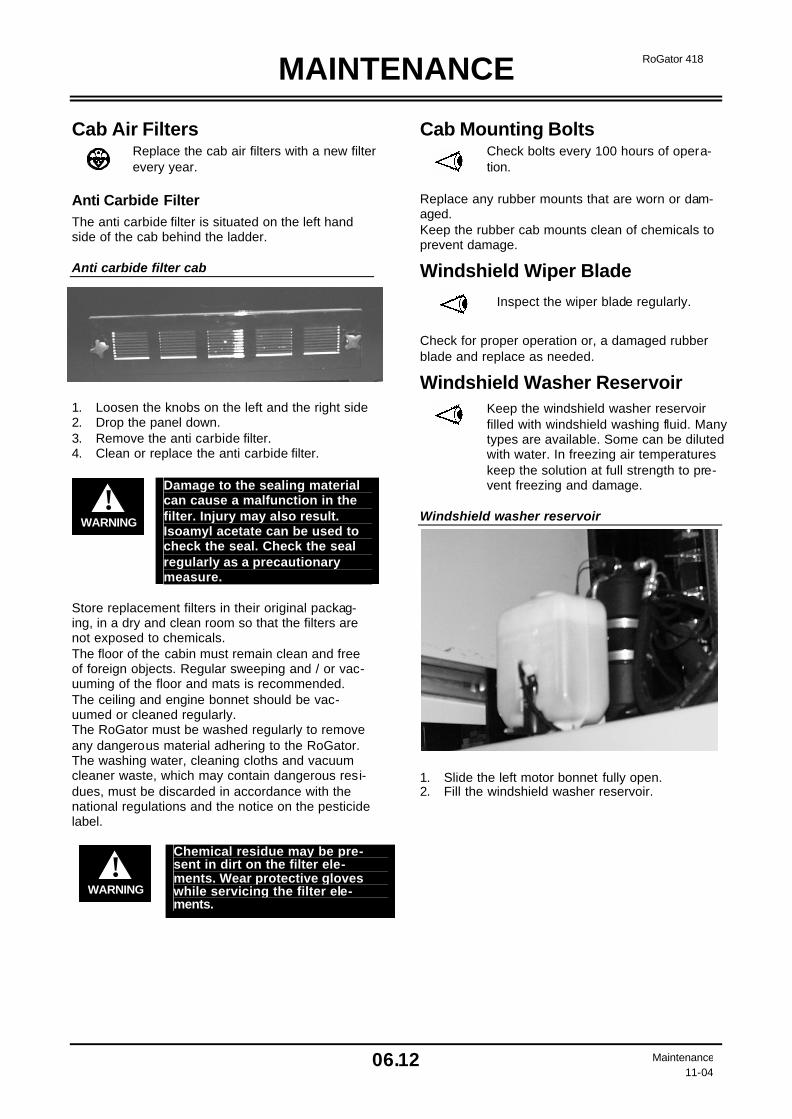
MAINTENANCE
06.12 Maintenance 11-04
RoGator 418
Cab Air Filters
Replace the cab air filters with a new filter every year.
Anti Carbide Filter The anti carbide filter is situated on the left hand side of the cab behind the ladder. Anti carbide filter cab 1. Loosen the knobs on the left and the right side 2. Drop the panel down. 3. Remove the anti carbide filter. 4. Clean or replace the anti carbide filter.
WARNING!
Damage to the sealing material can cause a malfunction in the filter. Injury may also result. Isoamyl acetate can be used to check the seal. Check the seal regularly as a precautionary measure.
Store replacement filters in their original packag-ing, in a dry and clean room so that the filters are not exposed to chemicals. The floor of the cabin must remain clean and free of foreign objects. Regular sweeping and / or vac-uuming of the floor and mats is recommended. The ceiling and engine bonnet should be vac-uumed or cleaned regularly. The RoGator must be washed regularly to remove any dangerous material adhering to the RoGator. The washing water, cleaning cloths and vacuum cleaner waste, which may contain dangerous resi-dues, must be discarded in accordance with the national regulations and the notice on the pesticide label.
WARNING!
Chemical residue may be pre-sent in dirt on the filter ele-ments. Wear protective gloves while servicing the filter ele-ments.
Cab Mounting Bolts
Check bolts every 100 hours of opera-tion.
Replace any rubber mounts that are worn or dam-aged. Keep the rubber cab mounts clean of chemicals to prevent damage.
Windshield Wiper Blade
Inspect the wiper blade regularly.
Check for proper operation or, a damaged rubber blade and replace as needed.
Windshield Washer Reservoir
Keep the windshield washer reservoir filled with windshield washing fluid. Many types are available. Some can be diluted with water. In freezing air temperatures keep the solution at full strength to pre-vent freezing and damage.
Windshield washer reservoir 1. Slide the left motor bonnet fully open. 2. Fill the windshield washer reservoir.

MAINTENANCE
06.13 Maintenance 11-04
RoGator 418
Hydraulic (Hydrostatic) System
Check the oil level daily. Make sure that the fluid reaches the top mark in the sight glass at operating temperature.
Check the hydraulic oil tank cap.
Check the hydraulic oil hoses, pipes and fittings for damage or leaks every 50 hours of operation. Check the hy-draulic cylinders for damage and leaks
Hydraulic oil level sight gauge
DANGER!
Do not open pressurised hy-draulic oil pipes or hoses. Do not use the hands to search for leaks. Pressurised hydraulic oil can cause fatal injury.
Replacing Hydraulic Fluid and Filters in Hydraulic System
Replace the oil every 1000 hours of operation or annually.
Replace the suction and return line fi l-ters and the leakage oil filter every 500 hours of operation or annually. Replace the hydraulic oil and the filters even if the hydraulic oil is contaminated and after repairs to larger components.
Replace the filter element also after the first 100 hours of operation and when services including the repair of a com-ponent are carried out.
Replace the filters if the warning light comes on.
Replacing the Suction and Return Line Filter 1. Put the vehicle on level ground. 2. Clean the filter element cover and the sur-
rounding area. 3. Loosen the four M10 nuts at the filter cover
the suction and return line filter. Lift the filter out by the handle.
4. Install the new filter element and the cover. 5. Fill oil until it reaches half way on the sight
glass. 6. Start the engine and check for leaks. Check
the oil level again after a short trial run. Hydraulic Oil tank 1. Oil fill cap 2. Leakage oil filter 3. Suction / return line filter
Replacing the Leakage Oil Filter 1. Put the vehicle on level ground. 2. Clean the filter element cover and the sur-
rounding area. 3. Loosen the cap on top off the filter. Lift the
filter out. 4. Install the new filter element and the cover. 5. Fill oil until it reaches half way on the sight
glass. 6. Start the engine and check for leaks. Check
the oil level again after a short trial run.
1 2 3
Important: Hydraulic hoses have a long working live. By weather influences and use under heavy conditions and normal aging the working live will reduce. There for is checking of hydraulic hoses by dam-aging and aging important for good functioning of your machine and the safety of the user and the environment. Replace immediately damaged and leaking hy-draulic hoses.

MAINTENANCE
06.14 Maintenance 11-04
RoGator 418
1
3 2
4
Heat Exchangers
Clean the heat exchangers and the con-denser of the air conditioning system every 100 hours of operation. Use pres-sure washer or compressed air.
Loosen the clamps of the engine hood and slide the hood side ways. Clean the heat exchangers and condenser with a pressure washer or com-pressed air. Heat Exchangers 1. Air Conditioner Condenser 2. Engine Radiator 3. Hydraulic Cooler 4. Charge Air Cooler
Electrical System Electrical System Safety
DANGER!
Ensure that not (fatal) injuries occur when starting a driverless vehicle. Do not start the engine if the starter will cause a short due to interchanged leads. The engine will start normally if the current is connected correctly. Do NOT start the vehicle when standing on the ground. Start the vehicle only from the seat if it is in neutral and the parking brake is applied.
DANGER!
The battery box involves dan-gers. Do NOT attempt to change a component in the battery box except for the battery.
DANGER!
Disconnect the battery terminals before beginning to service the electrical system.
DANGER!
NEVER charge a frozen battery. It could explode and cause se-vere personal injury. Let the battery warm up to 15 °C before using a charger.
DANGER!
NEVER use the battery box for stowage purposes. Shorts and explosions could result.
DANGER!
Lead-acid batteries make flam-mable and explosive gases. Keep arcs, sparks, and flames away. Never smoke near the battery.
IMPORTANT: Do operate the vehicle with the battery leads disconnected. Do use a fast charger; do not perform any welding on the RoGator with battery leads connected.
Batteries
Check that the battery leads are con-nected correctly and are clean. Turn off the battery disconnect switch and remove any acid or corrosion on the battery leads with a soda solution. To prevent corrosion lubricated the terminals with grease.
Inspect to see that the battery cables are clean and tight.
Turn off the Battery Disconnection Switch at the end of every working day.
Battery Disconnect Switch Battery Terminal Connection
WARNING!
Never charge a frozen battery. It can explode and cause serious personal injury. Let the battery warm to15.5°C. (60°F) before using a charger.
+ +
- -

MAINTENANCE
06.15 Maintenance 11-04
RoGator 418
Fuse Panel The fuse panel is located outside on the right side of the cab. If the fuses are blown or damaged, remove the four wing nuts to remove the panel to replace with the same type and size fuses.
F1: 20A Power switched fuse 8, 9, 10 F2A: 15A Dual beams on high beam F2B: 15A Single beam on high beam F3: 5A not used F4: 20A Road lights F5: 20A Tail lights F6: 10A Tail lights F7: 10A Tail lights F8: 20A Beacon F9: 20A Road lights F10: 20A Work lamps #3 F11: 20A Work lamps #1 F12: 20A Work lamps #4 F13: 20A Valves range select F14: 20A Power un switched fuse 5, 6, 7 F15: 15A Boom motion / track adjust F16: 15A Right amber flashing warning lights F17: 15A Left amber flashing warning lights F18: 20A Work lamps #2 F19: 15A Hazard lights F20: 10A Dash and courtesy lamps F21: 1A not used F22: 15A Acc. run enable F23: 15A Chair F24: 25A Wiper and washer F25: 10A Run, acc, start relays F26: 1A turn signal switch power F27: 5A Horn F28: 20A Foam marker and product control F29: 25A Blower fan - HVAC F30A: 10A Remote throttle GRP 1 F30B: 10A Remote throttle GRP 2 F31: 5A Fuel solenoid hold F32: 20A Air dryer / accessory F33: 10A Stop lamps F34: 20A Range select relay – suspension – ladder – All wheel steer F35: 20A Controller – dirty power F36: 10A Reverse lamps F37: 10A not used F38: 10A Controller – clean power F39: 10A Parking brake F40: 20A Power un switched fuse 1, 2 F41: 20A Radio F42: 20A Power un switched fuse 3, 4 F43: 15A Foam marker delivery F44: 20A Accessory power outlet – un switched F45: 10A Power for sensors F46: 5A Can Track F47: 1A Radio memory F48: 20A Power switched – cigarette lighter style
CAUTION!
IMPORTANT: Find the cause of blown fuses. Never put a jumper wire across to bypass a blown fuse.

MAINTENANCE
06.16 Maintenance 11-04
RoGator 418
Jump Starting If it is necessary to use an extra battery to start the engine, BE EXTREMELY CAREFUL. This is a two person operation. There must be one person in the operator's seat and one person to connect and disconnect the battery cables.
WARNING!
When connecting an extra ba t-tery for "jump" starting, make the last connection (negative cable) to the frame or engine (never at the battery). When removing the "jump" start ca-bles, remove the negative cable from the engine or frame first.
1. The key switch must be in the OFF position. 2. The battery to be used must be of the same
voltage as the one installed. 3. Battery terminals have identification marks.
The positive terminal is marked (+) and the negative terminal is marked (-). The negative terminal (-) of the battery must be connected to the engine.
4. If the booster battery is in another vehicle, do not operate the engine when making cable connections or starting the RoGator. This will prevent possible damage to the electrical system.
WARNING!
Be sure that the machines do not contact each other.
NOTE: Remove the cover from the positive terminal and from the negative terminal; re-place the covers on the terminals after charg-ing is completed. 5. Connect the end of the first cable to the posi-
tive terminal (+) of the booster battery. Con-nect the other end of the same cable to the positive terminal (+) of the RoGator battery.
6. Connect the end of the second cable to the
negative terminal (-) of the booster battery. Connect the other end of the second cable to the engine or frame. DO NOT connect the cable directly to the negative terminal (-) of the RoGator battery.
7. Start the RoGator engine.
8. After the engine has started, remove the ca-
ble connected to the RoGator engine or frame. Then remove the cable from the Ro-Gator battery positive terminal (+).
Storage of Vehicle If the vehicle is in storage for several months, the following procedures will help prevent excessive deterioration.
1. Replace the engine oil and filter. Operate the engine until it is warm to allow the new oil to circulate.
2. Drain, flush and fill the engine cooling system. Use a 50/50 solution of ethylene glycol antifreeze and soft clean water. Do not use stop leak additives.
3. Drain the fuel tank. Add a small amount of fuel and corrosion inhibitor.
4. Disengage battery lever. Remove, clean, charge and put the batteries in storage.
5. Paint all damaged spots and apply primer on all unpainted surfaces.
6. Blow out all air lines. 7. Make sure all components and systems are
cool. 8. Clean the vehicle, removing all mud, dirt,
grease and other foreign material. 9. To prevent rust, paint any damaged areas and
put corrosion inhibitor on unpainted metal (hydraulic cylinders, rods, control linkages, etc.).
10. If possible, put the vehicle in a dry, inside storage place. If it is necessary to put the vehicle in storage outside, cover it with a water resistant canvas or other acceptable material.
11. Loosen the engine drive belts. 12. Cover openings on the engine, transmission,
air cleaner intake, fuel tanks, electrical system and hydraulic system with plastic bags and tape.
13. Block the vehicle up so the tyres are not on the ground. Keep the tyres from heat, light and water.
Before Operating after Long Storage 1. Check the tire air pressure and remove the
blocks from the vehicle. 2. Remove all protective covers from the vehicle. 3. Tighten the engine bolts. 4. Remove the batteries from storage. Install the
batteries in the vehicle and connect the cables. Make sure the batteries have a full charge. Engage the battery lever.
5. Check the oil in the engine, transmission, hydraulic system and pressure washer pump. Add oil as necessary. Check radiator coolant level. Fill the fuel tanks.
MAINTENANCE
06.17 Maintenance 11-04
RoGator 418
Cab Seat Preventative Maintenance
Lubricate Adjusters Twice a Year Adjust seat back until it stops; apply a good amount of grease to the lower front of the adjust-ers. Move the seat forward until it stops, and grease the lower rear of the adjusters. Move the seat back and forward a few times.
Armrest Mechanism With mechanism in top position and armrest tilted up, spray in between halves of the structure with a spray lubricant. Lubricate twice a year.
Paint and Decals
Wash the vehicle with water and a de-tergent. Automotive cleaners and waxes can also be used. Paint areas that are damaged. Replace any decals or safety signs that are damaged or missing immediately.
Safety Treads Replace when there are signs of wear.
WARNING!
Failure to replace safety treads when needed can cause a slip-pery condition and a falling haz-ard which can cause severe in-jury or death.
MAINTENANCE PARTS – RG418
E000961 FILTER - FUEL E001439 FILTER - FUEL / WATER SEPARATOR E000960 FILTER - ENGINE OIL E250061 FILTER - ENGINE AIR - PRIMARY E250062 FILTER - ENGINE AIR - SECONDARY E001053 FILTER - CAB PRIMARY E250055 FILTER - HYDRAULIC TANK E250070 FILTER - HYDRAULIC TANK SMALL
Note: Do not substitute filters

COLD WEATHER OPERATION
07.1 Cold Weather Operation
11-04
RoGator 418
Minimising the Effect of Cold Weather
Caterpillar diesel engines are designed to operate effectively in cold weather.
However, for effective starting and cold weather operation, a little extra care is necessary. The in-formation below outlines steps that can minimize the effect that cold weather may have on starting and operation of your engine. See your authorized engine distributor or servicing dealer for additional information and local availability of cold weather aids. Use Winter Fuel When temperatures fall below 5°C (40°F), winter diesel fuel is recommended for your engine. (See also Operation and maintenance manual of the engine). Seasonal Viscosity Oil and Proper Coolant Concentration Use seasonal grade viscosity engine oil based on expected air temperature range between oil changes and a proper concentration of low silicate antifreeze as recommended. Idling the Engine Avoid excessive engine idling. Prolonged idling may cause the engine coolant temperature to fall below its normal range. This, in turn, causes crankcase oil dilution, due to incomplete fuel combustion, and permits formation of gummy deposits on valves, pistons, and piston rings. It also promotes rapid accumulation of engine sludge and unburned fuel in the exhaust system. Once an engine is warmed to normal operating temperatures, engine should be idled at slow idle speed. Slow idle speed for this engine is 750 rpm at factory. If an engine will be idling for more than 5 minutes, stop and restart later. Engine Coolant Specifications Contact your authorized servicing dealer or engine distributor to determine what the cooling system of this engine is filled with and the winter freeze pro-tection level. Coolant solutions of quality water, ethylene glycol concentrate (antifreeze), and supplemental coolant additives (SCA’s) MUST be used year-round for freeze protection, boil-over protection, liner erosion or pitting, and to provide a stable, noncorrosive environment for seals, hoses and metal engine parts.
Water Quality Water quality is important to the performance of the cooling system. Distilled, deionized, or demin-eralized water is recommended for mixing with ethylene glycol base engine coolant concentrate. Mineral (hard/tap) water should NEVER be put in a cooling system unless first tested.
Ethylene Glycol Concentrate (Antifreeze) IMPORTANT: Do NOT use ethyleneglyckol concentrate containing sealer or stop-leak ad-ditives. IMPORTANT: Never use automotive-type cool-ants (such as those meeting ASTM D3306 or ASTM D4656). These coolants do not contain the correct additives to protect heavy-duty diesel engines. They often contain a high con-centration of silicates and may damage the engine or cooling system.
Caterpillar Antifreeze/Summer Coolant Con-centrate This product contains ethylene glycol (low silicate antifreeze) and supplemental coolant additives (SCA’s). It must be mixed with quality water, as described in this section, before adding to the en-gine cooling system. The proportion of water to be used depends upon the lowest freeze protection temperature desired according to the following table: Concentrate (%) Freeze Protection Limit 50 -36 °C 60 -51 °C
Supplemental Coolant Additives (SCA’s)
IMPORTANT: Check inhibitors between the drain intervals every 600 hours or every 12 months. Replenish inhibitors by the addition of a supplemental coolant additive as necessary. Do NOT over inhibit antifreeze solutions. Additives eventually lose their effectiveness and must be recharged with additional Sup-plemental Coolant Additives (SCA’s) available in the form of liquid coolant conditioner. (See also Operation and maintenance manual of the engine).

COLD WEATHER OPERATION
07.2 Cold Weather Operation
11-04
RoGator 418
Diesel Engine Oil Use oil viscosity based on the expected air tem-perature range during the period between oil changes. The following oil is preferred: Viscosity grade SAE 15W-40 is preferred.
Engine Oil Viscosity Ambient Temperature 0C Caterpillar
DEO Multi-grade EMA LRG-1 API CH-4 API CG-4 and API CF-4 Viscosity Grade
Minimum Maximum
SAE 0W20 -40 10 SAE 0W30 -40 30 SAE 0W40 -40 40 SAE 5W30 -30 30 SAE 5W40 -30 40 SAE 10W30 -20 40 SAE 15W40 -15 50 (See also Operation and maintenance manual of the engine).
Mixing of Lubricants In General, avoid mixing different brands or types of oil. Oil manufacturers blend additives in their oils to meet certain specifications and performance re-quirements. Mixing different oils can interfere with the proper functioning of these additives and de-grade lubricant performance.
Grease Use grease based on the expected air temperature range during the service interval. The following greases are preferred: • High temperature Moly-Lithium base grease • Greases meeting Military Specification
MIL-G-10924F may be used as arctic grease.
50°C
40°C
30°C
20°C
10°C
0°C
-10°C
-20°C
-30°C
-40°C
122°F
104°F
86°F
68°F
50°F
32°F
14°F
-4°F
-22°F
-40°F -55°C -67°F
Mo
ly H
igh
#T
emp
EP
3104-48
NL
GI N
um
ber
0 N
LG
I Nu
mb
er 2
NL
GI N
um
ber
1
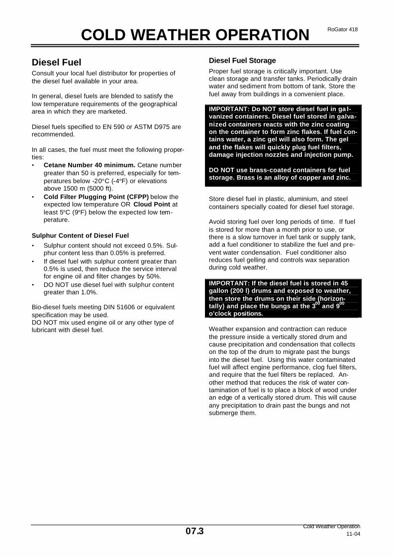
COLD WEATHER OPERATION
07.3 Cold Weather Operation
11-04
RoGator 418
Diesel Fuel Consult your local fuel distributor for properties of the diesel fuel available in your area. In general, diesel fuels are blended to satisfy the low temperature requirements of the geographical area in which they are marketed. Diesel fuels specified to EN 590 or ASTM D975 are recommended. In all cases, the fuel must meet the following proper-ties: • Cetane Number 40 minimum. Cetane number
greater than 50 is preferred, especially for tem-peratures below -20°C (-4°F) or elevations above 1500 m (5000 ft).
• Cold Filter Plugging Point (CFPP) below the expected low temperature OR Cloud Point at least 5°C (9°F) below the expected low tem-perature.
Sulphur Content of Diesel Fuel
• Sulphur content should not exceed 0.5%. Sul-phur content less than 0.05% is preferred.
• If diesel fuel with sulphur content greater than 0.5% is used, then reduce the service interval for engine oil and filter changes by 50%.
• DO NOT use diesel fuel with sulphur content greater than 1.0%.
Bio-diesel fuels meeting DIN 51606 or equivalent specification may be used. DO NOT mix used engine oil or any other type of lubricant with diesel fuel.
Diesel Fuel Storage Proper fuel storage is critically important. Use clean storage and transfer tanks. Periodically drain water and sediment from bottom of tank. Store the fuel away from buildings in a convenient place. IMPORTANT: Do NOT store diesel fuel in ga l-vanized containers. Diesel fuel stored in galva-nized containers reacts with the zinc coating on the container to form zinc flakes. If fuel con-tains water, a zinc gel will also form. The gel and the flakes will quickly plug fuel filters, damage injection nozzles and injection pump. DO NOT use brass-coated containers for fuel storage. Brass is an alloy of copper and zinc.
Store diesel fuel in plastic, aluminium, and steel containers specially coated for diesel fuel storage. Avoid storing fuel over long periods of time. If fuel is stored for more than a month prior to use, or there is a slow turnover in fuel tank or supply tank, add a fuel conditioner to stabilize the fuel and pre-vent water condensation. Fuel conditioner also reduces fuel gelling and controls wax separation during cold weather. IMPORTANT: If the diesel fuel is stored in 45 gallon (200 l) drums and exposed to weather, then store the drums on their side (horizon-tally) and place the bungs at the 300 and 900 o'clock positions. Weather expansion and contraction can reduce the pressure inside a vertically stored drum and cause precipitation and condensation that collects on the top of the drum to migrate past the bungs into the diesel fuel. Using this water contaminated fuel will affect engine performance, clog fuel filters, and require that the fuel filters be replaced. An-other method that reduces the risk of water con-tamination of fuel is to place a block of wood under an edge of a vertically stored drum. This will cause any precipitation to drain past the bungs and not submerge them.

LONG TERM STORAGE
08.1
RoGator 418
Long Term Storage
11-04
Long Term Storage Preparation The following storage preparations are good for long term engine storage up to one year. After that, the engine should be started, warmed up, and retreated for the extended storage period.
IMPORTANT: Any time your engine will not be used for over six (6) months, the following recommendations for storing it and removing it from storage will help to minimize corrosion and deterioration.
1. Change engine oil and replace filter. Used oil will not give adequate protection.
2. Service air cleaner
3. Draining and flushing of cooling system is not necessary if engine is to be stored only for several months. However, for extended storage periods of a year or longer, it is recommended that the cooling system be drained, flushed, and refilled. Refill with appropriate coolant.
4. Drain fuel tank and add 30 ml (1 oz) of inhibitor to the fuel tank for each 15 L (4 U.S. gal) of tank capacity. Completely drain fuel filter and close fuel valve, if equipped.
5. Add 30 ml (1 oz) of inhibitor to the engine crankcase for each 0.95 L (1 qt) of crankcase oil.
6. Disconnect air intake piping from the manifold. Pour 90 ml (3 oz) of inhibitor into intake system and reconnect the piping.
7. Crank the engine several revolutions with starter (do not allow the engine to start).
8. Remove fan/alternator V-belt, if desired.
9. Remove and clean batteries. Store them in a cool, dry place and keep them fully charged.
10. Clean the exterior of the engine with salt-free water and touch-up any scratched or chipped painted surfaces with good quality paint.
11. Coat all exposed (machined) metal surfaces with grease or corrosion inhibitor if not feasible to paint.
12. Seal all openings on engine with plastic bags and tape.
13. Storage should be a dry protected place. If outside storage is necessary, then use a suitable protective material for a cover and use a strong waterproof tape.
Long Term Storage Removal Refer to the appropriate section for detailed services listed below or have your authorized servicing dealer or engine distributor perform services that you may not be familiar with. 1. Remove all protective coverings. Unseal all
engine openings and remove covering from electrical systems.
2. Remove the batteries from storage. Install batteries (fully charged) and connect the terminals.
3. Install fan/alternator V-belts if removed.
4. Fill fuel tank.
5. Perform all appropriate prestarting checks.
6. Crank engine for 20 seconds with starter (do not allow the engine to start). Wait 2 minutes and crank engine an additional 20 seconds to assure bearing surfaces are adequately lubricated.
7. Start engine and run at low idle and no load for several minutes. Warm up carefully and check all gauges before placing engine under load.
8. On the first day of operation after storage, check overall engine for leaks and check all gauges for correct operation.
IMPORTANT: DO NOT operate starter more than 30 seconds at a time. Wait at least 2 minutes for starter to cool before trying again.

TROUBLESHOOTING
09.1 Troubleshooting 11-04
RoGator 418
Engine
PROBLEM POSSIBLE CAUSE CORRECTION
The engine will not start or starts hard.
→ Incorrect starting proce-dure.
→ Low or no fuel. → Air in fuel lines. → Incorrect engine oil viscos-
ity. → Incorrect fuel for operating
temperature. → Contaminated fuel system. → Clogged fuel filter. → Malfunctioning fuel injec-
tor(s). → Malfunctioning fuel solenoid
or solenoid relay. → Clogged air filter.
→ Review starting procedures.
→ Check the fuel level. → Bleed the fuel system. → Use correct viscosity oil.
→ Use correct type of fuel for
the temperature conditions. → Clean the fuel system. → Replace the filter element. → Contact Ag-Chem Europe
b.v. service centre. → Contact Ag-Chem Europe
b.v. service centre. → Clean or replace the air filter.
Starter speed low and the engine cranks slowly.
→ Connections loose or cor-roded.
→ Battery earth switch faulty. → Low battery voltage. → Incorrect viscosity of the
engine oil. → Starter defective.
→ Clean and tighten loose connections.
→ Check the battery earth switch.
→ Check that the battery open circuit voltage is 12.6 Volt minimum. Check the electro-lyte level and the specific gravity of each battery.
→ Use correct viscosity oil for the temperature conditions.
→ Contact Ag-Chem Europe b.v. service centre.
Engine runs rough and/or stalls. → Clogged fuel filter.
→ Restricted air filter. → Temperature of engine cyl-
inders too low for clean burning of fuel.
→ Fuel system contaminated. → Injection nozzle(s) defective.
→ Replace the filter. → Clean or replace the air filter. → Refer to "Cold Weather Op-
eration". → Clean the system. Contact
Ag-Chem Europe b.v. service centre.
→ Contact Ag-Chem Europe b.v. service centre

TROUBLESHOOTING
09.2 Troubleshooting 11-04
RoGator 418
Engine (Continues) Engine knocks → Low oil level.
→ Low oil pressure. → Engine overheated.
→ Add correct grade and amount of oil.
→ Contact Ag-Chem Europe b.v. service centre.
→ Refer to " Engine Over-heated".
Engine does not appear to develop full power
→ Engine overloaded.
→ Air filter restricted. → Clogged fuel filter. → Incorrect type of fuel. → Engine overheated. → Low engine operating tem-
perature. → Injection nozzle(s) defective. → High idle speed is low. → High charge air temperature.
→ Shift to lower speed range to reduce the engine load.
→ Service the air filter. → Replace the fuel filter. → Use the correct fuel. → Refer to " Engine Over-
heated". → Contact Ag-Chem Europe
b.v. service centre. → Contact Ag-Chem Europe
b.v. service centre. → Contact Ag-Chem Europe
b.v. service centre. → Clean the charge air cooling
system - contact Ag-Chem Europe b.v. service centre.
Electrical System
PROBLEM POSSIBLE CAUSE CORRECTION
The voltage in the electrical sys-tem is low.
→ Corroded or loose battery terminal connections.
→ Poor earth connection. → Shorted out electrical sy s-
tem. → Sulphated batteries. → Loose or worn belts.
→ Clean and tighten the con-nections.
→ Replace the earth switch. → Contact Ag-Chem Europe
b.v. service centre. → Check the battery open cir-
cuit voltage for 12.6 Volt. Check the electrolyte level and the specific gravity.
→ Check the belt tension, re-placing the belt if necessary.
Batteries not charging. → Corroded or loose battery
connections. → Sulphated batteries. → Loose or worn belts. → Alternator defective.
→ Clean and tighten the con-nections.
→ Check the battery open cir-cuit voltage for 12.6 Volt. Check the electrolyte level and the specific gravity.
→ Check the belt tension, re-placing the belt if necessary.
→ Replace the alternator.
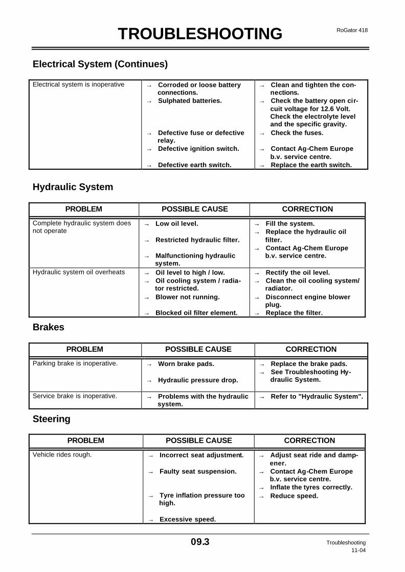
TROUBLESHOOTING
09.3 Troubleshooting 11-04
RoGator 418
Electrical System (Continues) Electrical system is inoperative → Corroded or loose battery
connections. → Sulphated batteries. → Defective fuse or defective
relay. → Defective ignition switch. → Defective earth switch.
→ Clean and tighten the con-nections.
→ Check the battery open cir-cuit voltage for 12.6 Volt. Check the electrolyte level and the specific gravity.
→ Check the fuses.
→ Contact Ag-Chem Europe b.v. service centre.
→ Replace the earth switch.
Hydraulic System
PROBLEM POSSIBLE CAUSE CORRECTION
Complete hydraulic system does not operate
→ Low oil level. → Restricted hydraulic filter. → Malfunctioning hydraulic
system.
→ Fill the system. → Replace the hydraulic oil
filter. → Contact Ag-Chem Europe
b.v. service centre.
Hydraulic system oil overheats → Oil level to high / low. → Oil cooling system / radia-
tor restricted. → Blower not running. → Blocked oil filter element.
→ Rectify the oil level. → Clean the oil cooling system/
radiator. → Disconnect engine blower
plug. → Replace the filter.
Brakes
PROBLEM POSSIBLE CAUSE CORRECTION
Parking brake is inoperative. → Worn brake pads. → Hydraulic pressure drop.
→ Replace the brake pads. → See Troubleshooting Hy-
draulic System.
Service brake is inoperative. → Problems with the hydraulic system.
→ Refer to "Hydraulic System".
Steering
PROBLEM POSSIBLE CAUSE CORRECTION
Vehicle rides rough. → Incorrect seat adjustment. → Faulty seat suspension. → Tyre inflation pressure too
high. → Excessive speed.
→ Adjust seat ride and damp-ener.
→ Contact Ag-Chem Europe b.v. service centre.
→ Inflate the tyres correctly. → Reduce speed.

TROUBLESHOOTING
09.4 Troubleshooting 11-04
RoGator 418
Cabin
PROBLEM POSSIBLE CAUSE CORRECTION
Dust enters the cabin. → Improper seal around the filter element.
→ Restricted filter. → Defective filter. → Excessive air leak(s) in cab
floor, windows, or door. → Pressurising fan not work-
ing.
→ Check seal condition. → Clean or replace the filter. → Replace the filter. → Seal air leak(s). → Repair the pressurising fan.
Pressurized air flow low. → Restricted filter. → Heater or vaporiser plugged.
→ Clean or replace the filter. → Contact Ag-Chem Europe
b.v. service centre. Cab windows fog up → Excessive moisture in cab
air system. → Position the air vents toward
the windows. Use the air conditioner system and re-circulation control along with the heating system to dehumidify the cab air.
Heating system does not heat → Defective engine thermo-stats.
→ Heater core is plugged.
→ Contact Ag-Chem Europe b.v. service centre.
→ Contact Ag-Chem Europe b.v. service centre.
Air conditioner does not cool → Condenser plugged.
→ Compressor belt slipping or
damaged. → Heater control turned on. → No air conditioning gas
→ Clean the radiator, the oil cooling system and the con-denser.
→ Check the tension and the condition of the drive belt.
→ Turn the temperature knob fully CCW for maximum cooling.
→ Contact Ag-Chem Europe b.v. service centre.

SPECIFICATIONS
10.1 Specifications 11-04
RoGator 418
NOTE: Specifications subject to change without notice.
Chassis Specifications Engine: Caterpillar 3056E engine, 6 liter engine, 6-cylinder, water-cooled, turbo charged diesel engine. 150 HP (112 kW) @ 2500 RPM.
Traction Pump: One pump, 140 cm3 / rev.
Wheel Motors: Mounted directly on the wheel, large and small displacement for three speed ranges and full-time all-wheel drive.
Service Brake (Option): Drum brake on each wheel.
Parking Brake: Multiple-disc brake in the rear wheel motors.
Steering: Hydraulic, load sensing type steering unit with pump mounted on the engine. Load-dependent open-centre steering system.
Frame: Made of S355J2G3 (ST52-3 N) 120 x 80 x 10 mm rectangular steel tubing with reinforcing cross beams full welded to frame.
Air cleaner: Dry type with centrifugal pre-cleaner, replaceable primary element, safety element.
Exhaust: Upright frame mounted behind cab.
Fuel Tank: Capacity: 200 L
Electrical system: 12 volt, negative ground with 120 amp alternator, two maintenance free batteries, two halogen work lights, two sealed beam halogen road lights with high/low beams, combination turn indicators/four-way flashers, tail/brakes lights, instrumental panel lights, cab entry lighting, triple utility outlets for cell phones, radios, etc. Fuse panel for lighting, elec-tronics, engine and other electrical, plus extra po-wer for added electrical use.
Hydraulic System: Closed circuit for drive system. Open circuit for extern Hydraulic functions. Open circuit for steer-ing system. 150 L hydraulic tank with temperature-meter, sender level, filling cap, gauge-view. Exter-nal oil cooler part of radiator.
Compressed Air System: Engine-driven compressor. Two compressed air reservoirs.
Cab: Three point rubber cab mount, Air-ride captain’s chair, seat belt, full view door, carbide filtration, multi duct heat and air conditioning, no high pres-sure fluids (product, hydraulic) in operator com-partment. Sound system. Two heavy -duty rectan-gular mirrors, 430 mm x 230 mm. Removable right hand window. Laminated windshield glass. Te m-pered side and rear glass. One complete vehicle electronic instrument panel . One rotating beacon, outside on the mirror support.
Turning radius: Standard chassis with wheelbase 3100mm, 2900 mm inside rear tire, 4930 mm outside front tire.
Tyres: • (4) 300/95 R46 Standard • (4) 540/65 R38 • (4) 420/85 R38
Ground Clearance: 110 cm with tyres 300/95 R46.
Speed Ranges: Speed range 1: 0 – 20 km/h Speed range 2: 0 – 30 km/h Speed range 3: 0 – 40 km/h

SPECIFICATIONS
10.2 Specifications 11-04
RoGator 418
Options:
• Tool box
• Spare parts kit
• Extra tires
• Crop shields wheel motor
• Central Lubrication System
• Tire Inflation System
• Traction control
• Speed ground radar
• Work Lights
• Radio-CD Player
Chassis weights*: Axle Weight
Front axle-weight: 4700 kg
Rear axle-weight:
1600 kg
Total-weight: 6400 kg
*) Fixed axles and Tires, 300/95 R46.
Dimensions:
418
ROGATOR 418ROGATOR
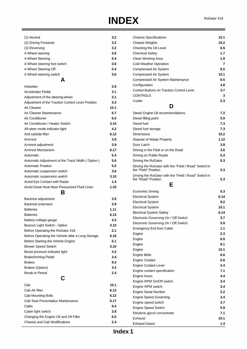
INDEX
Index 1
RoGator 418
(1) Neutral 3.2
(2) Driving Forwards 3.2
(3) Reversing 3.2
4-Wheel steering 3.6
4-Wheel Steering 5.4
4-Wheel steering foot switch 3.6
4-Wheel Steering Off 5.4
4-Wheel steering switch 3.6
A
Absorber 3.9
Accelerator Pedal 3.1
Adjustment of the steering wheel 3.1
Adjustment of the Traction Control Lever Position 3.3
Air Cleaner 10.1
Air Cleaner Maintenance 6.7
Air Conditioner 6.5
Air Conditioner / Heater Switch 3.10
All-steer mode indicator light 4.2
Anti carbide filter 6.12
Armrest 3.9
Armrest adjustment 3.9
Armrest Mechanism 6.17
Automatic 5.4
Automatic Adjustment of the Track Width ( Option ) 5.6
Automatic Position 5.5
Automatic suspension switch 3.6
Automatic suspension switch 3.10
Avoid Eye Contact with Radar 1.4
Avoid Great Heat Near Pressurized Fluid Lines 1.10
B
Backrest adjustment 3.9
Backrest extension 3.9
Batteries 1.11
Batteries 6.14
Battery voltage gauge 4.2
Beacon Light Switch - Option 3.10
Before Operating the RoGator 418 2.1
Before Operating the Vehicle after a Long Storage 6.16
Before Starting the Vehicle Engine 5.1
Blower Speed Switch 3.10
Boost pressure indicator light 4.2
Brake/Inching Pedal 3.4
Brakes 9.3
Brakes (Option) 3.4
Break-in Period 2.4
C
Cab 10.1
Cab Air filter 6.12
Cab Mounting Bolts 6.12
Cab Seat Preventative Maintenance 6.17
Cabin 9.4
Cabin light switch 3.8
Changing the Engine Oil and Oil Filter 6.5
Chassis and Cab Modifications 2.4
Chassis Specifications 10.1
Chassis Weights 10.2
Checking the Oil Level 6.5
Chemical Safety 1.7
Clean Working Area 1.9
Cold Weather Operation 7
Compressed Air System 6.5
Compressed Air System 10.1
Compressed Air System Maintenance 6.5
Configuration 4.8
Control Buttons on Traction Control Lever 3.7
CONTROLS 3
Cooler 2.3
D
Diesel Engine Oil recommendations 7.2
Diesel filling point 5.9
Diesel fuel 7.3
Diesel fuel storage 7.3
Dimensions 10.2
Dispose of Waste Properly 1.12
Door Latch 3.8
Driving in the Field or on the Road 3.6
Driving on Public Roads 5.4
Driving the RoGator 5.3
Driving the RoGator with the “Field / Road” Switch in the “Field” Position 5.3
Driving the RoGator with the “Field / Road” Switch in the “Road” Position 5.3
E
Economic Driving 5.3
Electrical System 6.14
Electrical System 9.2
Electrical System 10.1
Electrical System Safety 6.14
Electronic Governing On / Off Switch 3.7
Electronic Governing On / Off Switch 5.9
Emergency Exit from Cabin 1.1
Engine 2.3
Engine 6.5
Engine 9.1
Engine 10.1
Engine Belts 6.6
Engine Coolant 6.6
Engine Coolant Level 2.4
Engine coolant specification 7.1
Engine hours 4.4
Engine RPM On/Off switch 3.4
Engine RPM switch 3.4
Engine Serial Number 2.2
Engine Speed Governing 3.4
Engine speed switch 3.7
Engine Speed Switch 5.9
Ethylene glycol concentrate 7.1
Exhaust 10.1
Exhaust Gases 1.4

INDEX
Index 2
RoGator 418
External Lighting and Temperature Control Panel in the Cabin 3.1
F
Fast Speed Range Switch 3.7
Field Position 3.2
Field Position 3.2
First 100 Hours of Operation 2.4
Follow Safety Instructions 1.1
Fore / aft adjustment 3.9
Fore / aft isolator 3.9
Frame 10.1
From inside the cab 3.4
From the remote switch box 3.4
Front axle in middle position indicator light 4.2
Front Axle Suspension ( Option ) 5.5
Fuel 6.8
Fuel Filter 6.8
Fuel level gauge 4.2
Fuel Storage 6.8
Fuel Tank 6.8
Fuel Tank 10.1
Fuse Panel 6.15
G
General 4.4
General description GEM 4.3
Getting started 4.3
Grease 7.2
Ground Clearnance 10.1
H
Hazard Warning Light Switch (Orange Flashing Warning Lights) 3.10
Heat Exchanger 6.14
Height adjustment 3.9
High beam ON indicator light 4.2
High-Pressure Fluids 1.10
Hydraulic (Hydrostatic) System 6.13
Hydraulic Hoses 1.10
Hydraulic oil level indicator light 4.2
Hydraulic Skid Regulator (option) 5.5
Hydraulic System 2.4
Hydraulic System 9.3
Hydraulic System 10.1
Hydraulic System – Operation at Low Temperatures 5.2
Hydrostatic Drive 2.3
I
Identification 2.2
Idling the engine 7.1
Ignition Switch 3.6
INDEX INDEX
Inner Filter Element 6.8
Installing the Wheels 6.11
Instrument Panel 3.5
INSTRUMENT PANEL 4
Instrument panel dashboard 4.1
INTRODUCTION 2
J
Jump Starting 6.16
K
L
Left turn signal light 4.2
Lighting and door handling of the cab 3.8
Location of Components. 2.6
Location of Safety and Service Decals Cabin 1.15
Location of Saf ety and Service Decals Chassis 1.13
Location of seat controls 3.9
LONG TERM STORAGE 8
Long Term Storage Preparation 8.1
Long Term Storage Removal 8.1
Low-pressure Pump 2.3
Lubricant Filling Reminders 6.1
Lubricants and Fluids 6.1
Lubricate Adjusters Twice a Year 6.17
Lumbar support 3.9
M
MAINTENANCE 6
Maintenance and Service Safety 1.8
Maintenance Introduction 6.1
Maintenance of the sliding axle 5.8
Maintenance Parts RG618 6.17
Maintenance Schedule 2.4
Maintenance Schedule 6.3
Maintenance Symbols 6.2
Manual 5.4
Manual Position 5.5
Manual suspension switch 3.6
Manual suspension switch 3.10
Master Switch 3.7
Minimising the effect of cold weather 7.1
Mixing of lubricants 7.2
Mobile Radio 2.5
Mobile Radio Installations 1.12
Modifications 1.6
Motor Platform 5.9
N
Noise 1.5
O
Oil temperature indicator light 4.2
Operating on Slopes 1.3
Operation 3.1
OPERATION 5
Operation 5.4
Options 10.2
Overhead Electrical Power Lines 1.5
P
Paint and Decals 6.17
Parking Brake 3.4
Parking Brake 10.1

INDEX
Index 3
RoGator 418
Parking brake warning light 4.2
Pop-up messages and warnings 4.7
Positions of the Traction Control Lever 3.2
Practice Safe Maintenance 1.8
Preparation for Emergencies 1.1
Prevent Vehicle Runaway 1.2
Primary Filter Element 6.7
Priming of the Fuel System 6.9
Proper Lifting Equipment 1.9
Proper Servicing 1.9
Proper Support of Vehicle 1.9
Q
R
Rear axle in middle position indicator light 4.2
Remote Throttle Control 3.7
Remote Throttle Control 5.9
Removal of Paint before Welding or Heating 1.11
Removing the Wheels 6.11
Replace the Fuel Filter 6.8
Replacing Hydraulic Fluid and Filters in Hydraulic System 6.13
Replacing the Leakage Oil Filter 6.13
Replacing the Suction and Return Line Filter 6.13
Res 1 / Res 2 3.7
Res 1/ Res 2 5.9
Reset button speedometer 4.2
Restarting a Stalled Engine 5.2
Right turn signal light 4.2
Road Position 3.2
Road Position 3.2
RoGator towing Procedure 2.5
S
Safe Handling of Fuel - Avoid Fires 1.5
Safe Operation of the Vehicle 1.2
Safe Servicing of Cooling System 1.10
SAFETY 1
Safety Treads 6.17
Safety Treads and Grips 1.6
Seasonal viscosity Oil and Proper coolant concentration 7.1
Seat 3.9
Seat depth adjustment 3.9
Seat pan angle adjustment 3.9
Separate Ladder 5.9
Serial Number Identification Plates 2.2
Service Brake (Option) 10.1
Setting display contrast and lighting 4.4
Setting the Track Width 5.6
Sliding the Axle 5.6
Slow Speed Range Switch 3.7
SPECIFIACTIONS 10
Speed Ranges 10.1
Speed Ranges: 5.3
Speedometer 4.2
Spray pump On / Off 3.7
Spray pump On / Off 5.9
Starting at Low Temperatures 5.2
Starting the Engine 5.2
Stay Clear of Rotating Power Takeoffs and Moving Parts 1.6
Steering 9.3
Steering 10.1
Stop lamp 3.10
Stopping and Parking the Vehicle 1.4
Storage of Vehicle 6.16
Suction / return line filter and leak oil filter indicator light 4.2
Sun Visor 3.8
Supplement coolant additives (SCA's) 7.1
Supplemental Coolant Additives (SCA’s) 6.6
Suspension 3.6
Switch for 4-Wheel Steering 5.4
Switching the skid regulator On/Off 5.5
Switching the spray computer On/Off 3.7
Swivel 3.9
System Boom Safety 1.4
T
Tank and Filter 2.3
Temperature Control Knob 3.10
The alarm display screen 4.7
The graph display 4.6
The main engine display 4.4
The quad and graph parameters 4.6
The quad display 4.5
Towing 2.4
Towing Other Vehicles 1.6
Towing with Engine Disabled 2.4
Towing with Engine Operable 2.4
Track width 1,50 - 2,00 m (Front axle) 5.7
Track width 1,80 - 2,25 m (Front axle) 5.7
Track width 2,00 - 2,25 m (Front axle) 5.8
Traction Control Lever 3.2
Traction Control Lever, Pump and Wheel Motors 2.3
Traction Pump 10.1
Transmission in first gear indicator light 4.2
Transmission in second gear indicator light 4.2
Transmission in third gear indicator light 4.2
Transmission neutral indicator light 4.2
Transport 2.5
Travelling on Public Roads 1.3
Travelling on Public Roads 5.9
Trip engine hours 4.4
TROUBLESHOOTING 9
Turn Signal, Lights and Horn Lever 3.1
Turning Machine Off with Rear Wheels Steered 5.4
Turning Radius 10.1
Turning the Controller On and Off 3.4
Two-wheel-steer mode indicator light 4.2
Tyre Maintenance 6.10

INDEX
Index 4
RoGator 418
Tyre Mounting 6.10
Tyre Pressure Chart 6.11
Tyres 10.1
Tyres and Wheels 1.11
U
Use of Proper Tools 1.9
Use of Safety Lights and Safety Devices 1.3
Using the soft keys 4.4
V
W
Warning / cold start lamp 3.10
Water quality 7.1
Wear Protective Clothing 1.8
Weight adjustment 3.9
Wheel Maintenance 6.11
Wheel Motors 10.1
Wheel Mounting Bolts 2.4
Windshield Washer Reservoir 6.12
Windshield Wiper Blade 6.12
Work Light Switch Four 3.10
Work Light Switch One 3.10
Work Light Switch Three 3.10
Work Light Switch Two 3.10
X
Y
Z