AT6SD KEYBOARD CONTROLLER
13
AT6SD KEYBOARD CONTROLLER Instruction manual (ref. Mi 3146) Please read carefully and completely this manual before install the product and keep for future reference
Transcript of AT6SD KEYBOARD CONTROLLER

AT6SDKEYBOARD
CONTROLLERInstruction manual
(ref. Mi 3146)Please read carefully and completely this manual before install the product
and keep for future reference

2
CONTENTS
1. Advisement ………………………………………………………. 42. Confirming the Contents of the Package ……………………... 63. Main Features and Functions …………………………………. 74. Appearance and Function Key ………………………………… 85. Functions and Operations ……………………………………. 10
1) Initial Setup of Keyboard2) Choice of Camera 3) Joystick and the Manual operation of Camera4) Camera Setup (How to enter into OSD menu)5) Preset Point6) Swing7) Group8) Tour9) Spiral Function10) PTZ trace11) Camera Remote Reset12) Brightness Control of LCD13) Alarm On / Off
6. Maintenance and Mending …………………………………… 197. Connections ………………………………………………..…... 208. General Specifications ………………………………………… 21
1) Controller2) Junction box3) DC Power Supply4) Camera Control Interface5) Constitution of Junction box pin6) Constitution of pin between Controller and Junction box
9. Quick Reference ……………………………………………… 24

3
1. Advisement WARNING
Always have the unit installed by the store it was purchased from.• Improper connections and/or installation could result in electrical shack,
fire or other serious injury or damage.Do not place the unit on an unstable surface.• Always checks the strength and stability of the installation location.• A falling unit will result in damage and could cause serious injuryNever disassemble or attempt to repair or modify the unit.• Disassembly by untrained personnel could result in serious electrical
shock, fire and/or malfunction.Never use in locations where combustible materials are used.• The unit should never be used where combustible materials, such as
gases, are being used.• Fire, explosion or other serious accidents could occur.Never touch electrical connections with wet hands.• Touching electrical connections with wet hands could result in serious
electrical shock.Never expose the unit to water.• If the unit becomes wet, turn off the power and unplug it immediately.• Stop using the unit if it becomes wet and contact your nearest dealer.Never use the unit if there is an abnormality.• Turn off the power and unplug the unit immediately if there is any type of
abnormality, such as a strange smell or smoke.• Continuing to use a unit that is not operation properly could result in
serious injury or damage ta the unit.Always use the designated power supply.• Failure to use the proper power supply could result in fire, electrical shock,
serious injury and/or damage.• Always uses the designated power supply.Always handle the connecting cords properly.• Never damage or modify the connecting cords.• Never pull on the connecting cord, expose them to extreme heat and/or
place heavy objects on top of them.• Failure to follow these warnings could result in fire, electrical shock or
other damage or injury.
CAUTION
Always use the unit indoors.• The unit should never be used outdoors, or in any place where it will be
exposed to rain or other extremes of moisture.• Direct exposure to water will result in rust and will damage the unit.Never use in environments that have heavy concentrations of dust,smoke, steam or humidity.• Environments such as these could result in fire, electrical shock or other
serious damage or injury.Never place the unit in extremes of high or low temperatures.• Extreme temperatures will damage the unit.• Always use within an operating range of 0 °C to 40 °C.Never mount in areas exposed to direct sunlight.• Direct sunlight can also discolor the unit and cause other damage.Never expose the unit to impact.• Strong impact may seriously damage the unit.
FOR PROPER OPERATION
Never install the unit yourself.• The unit should be installed by trained personnel.
This product has been designed and manufactured in accordance with theharmonized European standards, following the provisions of the below stateddirectives.Electromagnetic Compatibility Directive 89/336/EEC (EN 61000-3-2:1995,EN 61000-3-3:1995, EN 50081-1:1992, EN 50082-1:1997).
This devise complies with part 15 of the FCC rules operation is subject to thefollowing two conditions: (1) This device may not cause harmful interterenceand (2) This device must accept any interference received includinginterference that may cause undesired operation.
4
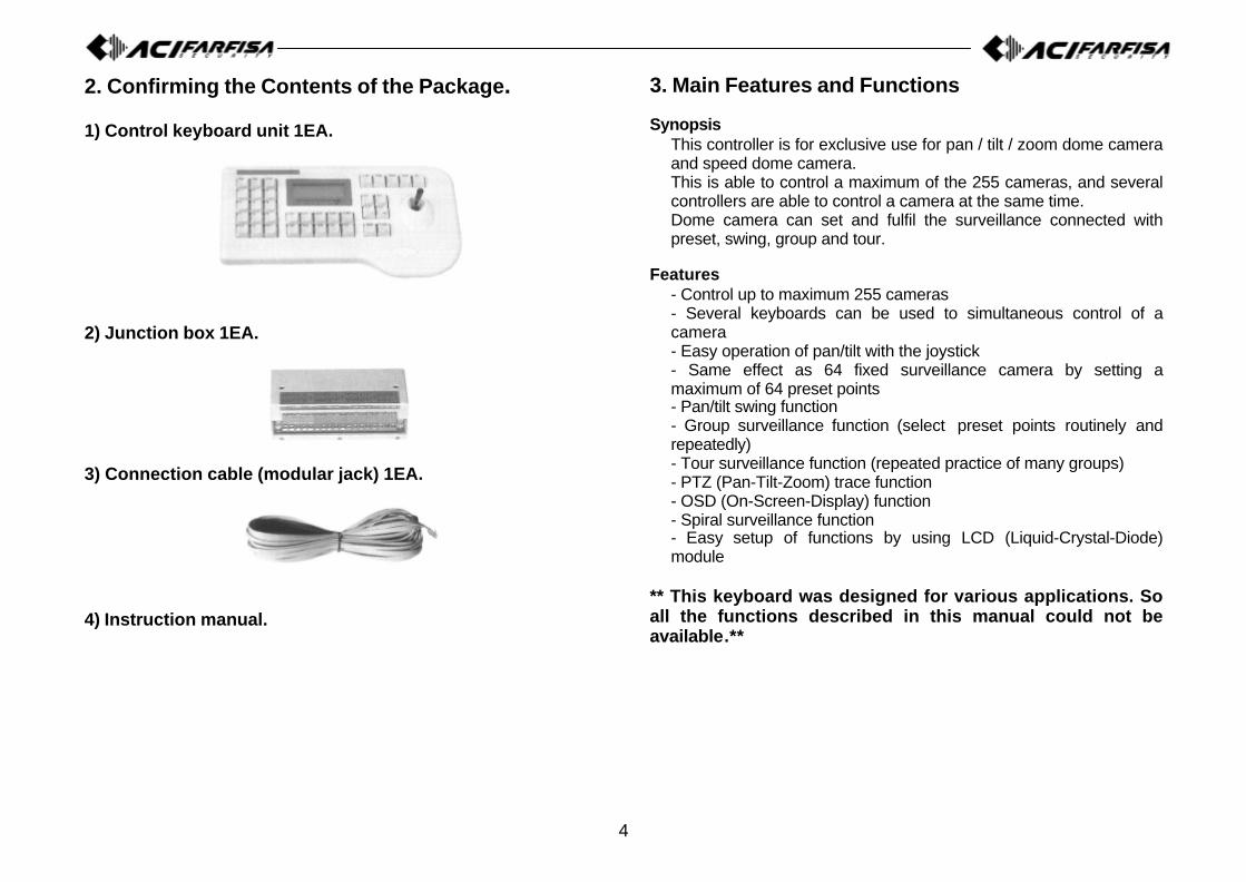
2. Confirming the Contents of the Package.
1) Control keyboard unit 1EA.
2) Junction box 1EA.
3) Connection cable (modular jack) 1EA.
4) Instruction manual.
3. Main Features and Functions
SynopsisThis controller is for exclusive use for pan / tilt / zoom dome cameraand speed dome camera.This is able to control a maximum of the 255 cameras, and severalcontrollers are able to control a camera at the same time.Dome camera can set and fulfil the surveillance connected withpreset, swing, group and tour.
Features- Control up to maximum 255 cameras- Several keyboards can be used to simultaneous control of acamera- Easy operation of pan/tilt with the joystick- Same effect as 64 fixed surveillance camera by setting amaximum of 64 preset points- Pan/tilt swing function- Group surveillance function (select preset points routinely andrepeatedly)- Tour surveillance function (repeated practice of many groups)- PTZ (Pan-Tilt-Zoom) trace function- OSD (On-Screen-Display) function- Spiral surveillance function- Easy setup of functions by using LCD (Liquid-Crystal-Diode)module
** This keyboard was designed for various applications. Soall the functions described in this manual could not beavailable.**

5
4. Appearance and Function Key1) Controller function button
2) Setting method of Junction box- Camera controls 1This is the input and output terminal. Connect 485+ to data + and 485–to data –.When you communicate with RS-485, the left switch of Junction boxmust be set backward.When you communicate with RS-422, the left switch of Junction boxmust be set forward.- Camera controls 2Same as camera control 1.- Sub KeyboardSub keyboard must be used only with sub keyboard and linked withsame line.n communicating with RS-485, the right switch of Junction box must beset backward (DC Jack direction).In communicating with RS-422, the right switch of Junction box mustbe set forward.- Junction box’ s input and output terminalThis terminal informs you that the data in/out in electronic transmissionof long distance, can be used as a data in/out transmission signal incommunicating with RS-485.In transmitting from keyboard to camera, you have to exteriorly pull upbecause, the camera receive reversely, such as when you send “high”,you get “low”, so pull up outside.“Exteriorly pull up” is?Don’ t put pull up resistance to collector of Transistor and make ’Theline driver’ pull up, then it can function normally.AscertainThe check voltage of GND and RTS should be over 5V.CautionSub keyboard can function only in general control.Under the situation that alarm is on in main keyboard, you can hearalarm sound when something is in disorder.Data line using for control of camera only connected to main Junctionbox, can makes sub keyboard function.
ALL ButtonSimultaneous on/off ofcameras, lights and AUX1.(only for receiver unit)
GROUP ButtonThis button is used to monitorthe preset pionts sequentially.
TOUR ButtonThis button is used to monitorthe groups sequentially.
SET ButtonThis button is used to start thesetting mode of various function.
Z/I (Zoom In), Z/O (Zoom Out) ButtonOperate the zoom control ofcamera.
AUX (Auxiliary) ButtonsThese buttons are used to controlof Auto-Pan (AUX1) and other unit(AUX2). (Only for receiver unit).
ALARM ButtonsThis button is used to on/off ofregistered video motion detection.
SWING ButtonThis button is used to move thecamera between two preset points.P-Set (Preset) ButtonThis button is used to input andconfirmation of preset points. (Max.64 positions each camera).
RUN Button#Numeric Keypad (0-9)These keys are used tomake input for settings andother functions.
HOLD Button#
ENTER ButtonThis button is used to savewhen camera or program isinputted
CLR (Clear) ButtonThis button is used to clearwrong number of function.
L/P (Light Power) ButtonThis button is used to on/off thelight. (only for receiver unit)
C/P (Camera Power) ButtonThis button is used to on/off thecamera. (only for receiver unit)
MON (Monitor) Button#CAM (Camera) ButtonThis button is used toselect a camera.View Button#ON ButtonThis button is used toexecute the functions.
OFF ButtonThis button is used tostop the functions.
MENU ButtonThis button is used to set upthe function with number button(Refer to function guide).
F/F (Focus Far), F/N (Focus Near)ButtonOperate the focus control ofcamera.STATUS ButtonThis button is used to freezeon/off of Video-out signal.
JoystickThis stick is used to controlpan/tilt and move the cursor inthe OSD menu.#: This button is allowed to be used only for the control of
matrix system. Not allowed for speed dome camera control.

6
5. Functions and Operations
Main keyboard is setup for normal products. So sub keyboard needs tobe setup. (If you want to use sub keyboard, please ask to the supplierof it.) First, switch “on” of dome camera, let the keyboard supply withelectricity.
1) Initial Setup of keyboardSupply the power first (put in connected power line) and then the menuscreen (Figure 1-1) appears on LCD with a sound.
Picture 1-1 Picture 1-2
2) Choice of camera
Select camera: Keypad 1-255 + CAM
3) Joystick and the manual operation of cameraThe camera used in “2) the choice of camera” can be operatedmanually by joystick. You can make up pan and tilt by joystick.¬¬ Upward TiltWhen joystick is operated upwardly, it will make the camera move upand the upper part of the color monitor can be viewed. Downward TiltWhen joystick is operated downward, it will make the camera movedown and the lower part of the color monitor can be viewed.®® Left PanWhen joystick is operated to leave, it will make the camera move to leftand the left part of the color monitor can be viewed.¯̄ Right PanWhen joystick is operated to right, it will make the camera move toright and the right part of the color monitor can be viewed.°° Simultaneous operation of pan/tiltOperating joystick the direction of diagonal, lead pan and tilt to work atthe same time. The velocity of joystick varies according to the tiltingangle.±± F/F button“Focus Far” button as a manual makes the focus lens of camera drivedrawing a circle. Also, it is used as a “ENTER” button in OSD menu.²² F/N button“Focus Near” button as manual makes the focus lens of camera move.Also, it is used as “ESCAPE” button in OSD menu.
Please wait !
Version 2.3
<CCTV Transmitter>
Camera:001Input? ¡ [MAIN]

7
4) Camera setup (How to enter into OSD menu)- OSD (On Screen Display) controlThis controller can be used to control speed dome camera, ptz domecamera with OSD menu.Please, refer also to camera OSD menu to avoid conflict insettings.
- How to enter into OSD Menu
Pressing numeric keypad 1 and MENU button respectively enableOSD (On Screen Display) Menu to mark on the monitor.• The delay time between push 1 button and MENU button is about
2-3 sec.
- The shift of cursor in OSD is as follows.¬ Left cursor - Joystick pan left (For speed dome camera only) Right cursor - Joystick pan right (For speed dome camera only)® Up cursor – Joystick tilt up (For speed dome camera only)¯ Down cursor - Joystick tilt down (For speed dome camera only)° Enter F/F button (For speed dome camera, ptz dome camera)± ESC – F/N button (For speed dome camera, ptz dome camera)² Up cursor – Z/I button (For ptz dome camera only)³ Down cursor – Z/O button (For ptz dome camera only)
- How to save and quit in OSD.Keypad “1” + “MENU”After setup or change parameters, press again numeric keypad 1 andMENU button respectively enable OSD(On Screen Display) Menu tomark on the monitor.• The delay time between push 1 button and MENU button is about
2-3 sec.
5) Preset PointThe controller makes to memorise 64 sets of the individual presetposition for each camera.The memorised preset point is available in resetting of power, and itcan be changed.
- Starting the preset modeSET + Keypad 1-64 + PSTThis mode enable pan/tilt and zoom/focus far/near work by joystick.Thus it can move the point of setting. After put and stop it in place youwant to surveillance, and set it following these orders.Appoint preset point no. of the present position with keypad. Operatewith joystick and zoom, focus button, and press the PST button, then itmemorises the number 1 Preset. At this moment, it also memorisesbrightness, BLC, WDR, S-BLC. If you want to memorise anotherposition with preset point, move to the joystick and repeat. The inputwill be ignored, if preset no. Input is out of range between 1-64.- Movement to a preset pointAppoint preset point number with numeric keypad. Appoint the numberof preset of 1-64 Ü Pressing the PST button automatically enable it tomove to appointed point.When the error occurs, two times of beep sound.- Deleting each presetPress the CLR button for a while (more then 3sec)Keypad 1-64 Ü PST button Ü ENT buttonEx) deleting the number 5 of preset:CLR (more then 3sec) Ü Keypad 5 Ü PST button Ü ENT button- Deleting all presetPress the CLR button for a while (more then 3sec) Ü PST button ÜENT button.
8
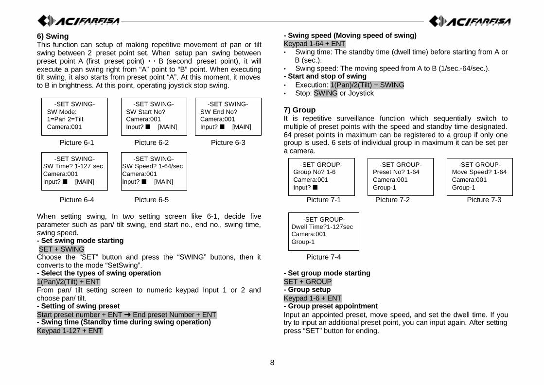
6) SwingThis function can setup of making repetitive movement of pan or tiltswing between 2 preset point set. When setup pan swing betweenpreset point A (first preset point) Ö B (second preset point), it willexecute a pan swing right from “A” point to “B” point. When executingtilt swing, it also starts from preset point “A”. At this moment, it movesto B in brightness. At this point, operating joystick stop swing.
Picture 6-1 Picture 6-2 Picture 6-3
Picture 6-4 Picture 6-5
When setting swing, In two setting screen like 6-1, decide fiveparameter such as pan/ tilt swing, end start no., end no., swing time,swing speed.- Set swing mode starting SET + SWINGChoose the “SET” button and press the “SWING” buttons, then itconverts to the mode “SetSwing”.- Select the types of swing operation1(Pan)/2(Tilt) + ENTFrom pan/ tilt setting screen to numeric keypad Input 1 or 2 andchoose pan/ tilt.- Setting of swing presetStart preset number + ENT Ü End preset Number + ENT- Swing time (Standby time during swing operation)Keypad 1-127 + ENT
- Swing speed (Moving speed of swing)Keypad 1-64 + ENT• Swing time: The standby time (dwell time) before starting from A or
B (sec.).• Swing speed: The moving speed from A to B (1/sec.-64/sec.).- Start and stop of swing• Execution: 1(Pan)/2(Tilt) + SWING• Stop: SWING or Joystick
7) GroupIt is repetitive surveillance function which sequentially switch tomultiple of preset points with the speed and standby time designated.64 preset points in maximum can be registered to a group if only onegroup is used. 6 sets of individual group in maximum it can be set pera camera.
Picture 7-1 Picture 7-2 Picture 7-3
Picture 7-4
- Set group mode startingSET + GROUP- Group setupKeypad 1-6 + ENT- Group preset appointmentInput an appointed preset, move speed, and set the dwell time. If youtry to input an additional preset point, you can input again. After settingpress “SET” button for ending.
-SET SWING-SW Mode:1=Pan 2=TiltCamera:001
-SET SWING-SW Start No?Camera:001Input? n [MAIN]
-SET SWING-SW End No?Camera:001Input? n [MAIN]
-SET SWING-SW Time? 1-127 secCamera:001Input? n [MAIN]
-SET SWING-SW Speed? 1-64/secCamera:001Input? n [MAIN]
-SET GROUP-Group No? 1-6Camera:001Input? n
-SET GROUP-Preset No? 1-64Camera:001Group-1
-SET GROUP-Move Speed? 1-64Camera:001Group-1
-SET GROUP-Dwell Time?1-127secCamera:001Group-1
9
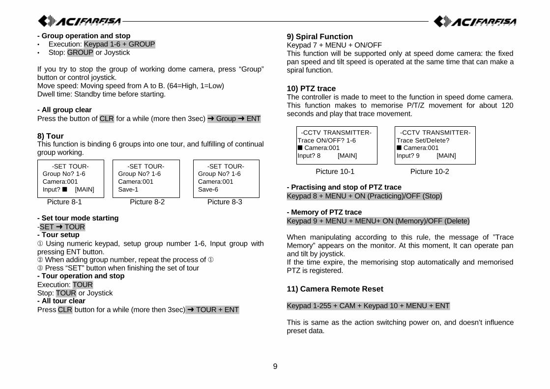
- Group operation and stop• Execution: Keypad 1-6 + GROUP• Stop: GROUP or Joystick
If you try to stop the group of working dome camera, press “Group”button or control joystick.Move speed: Moving speed from A to B. (64=High, 1=Low)Dwell time: Standby time before starting.
- All group clearPress the button of CLR for a while (more then 3sec) Ü Group Ü ENT
8) TourThis function is binding 6 groups into one tour, and fulfilling of continualgroup working.
Picture 8-1 Picture 8-2 Picture 8-3
- Set tour mode starting-SET Ü TOUR- Tour setup¬ Using numeric keypad, setup group number 1-6, Input group withpressing ENT button. When adding group number, repeat the process of ¬® Press “SET” button when finishing the set of tour- Tour operation and stopExecution: TOURStop: TOUR or Joystick- All tour clearPress CLR button for a while (more then 3sec) Ü TOUR + ENT
9) Spiral FunctionKeypad 7 + MENU + ON/OFFThis function will be supported only at speed dome camera: the fixedpan speed and tilt speed is operated at the same time that can make aspiral function.
10) PTZ traceThe controller is made to meet to the function in speed dome camera.This function makes to memorise P/T/Z movement for about 120seconds and play that trace movement.
Picture 10-1 Picture 10-2
- Practising and stop of PTZ traceKeypad 8 + MENU + ON (Practicing)/OFF (Stop)
- Memory of PTZ traceKeypad 9 + MENU + MENU+ ON (Memory)/OFF (Delete)
When manipulating according to this rule, the message of ”TraceMemory” appears on the monitor. At this moment, It can operate panand tilt by joystick.If the time expire, the memorising stop automatically and memorisedPTZ is registered.
11) Camera Remote Reset
Keypad 1-255 + CAM + Keypad 10 + MENU + ENT
This is same as the action switching power on, and doesn’t influencepreset data.
-SET TOUR-Group No? 1-6Camera:001Input? n [MAIN]
-SET TOUR-Group No? 1-6Camera:001Save-1
-SET TOUR-Group No? 1-6Camera:001Save-6
-CCTV TRANSMITTER-Trace ON/OFF? 1-6n Camera:001Input? 8 [MAIN]
-CCTV TRANSMITTER-Trace Set/Delete?n Camera:001Input? 9 [MAIN]

10
12) Brightness control of LCD
Keypad 20 + MENU + Joystick up/down + CLR
This function is controlling the brightness of LCD and being able to beused where there is the difference of brightness.
13) Alarm on / off
In setting Alarm on, the camera with setting MD on can result inbuzzer.When MD perceive sense, MD flickers with the sound of buzzer.When setting Alarm off, buzzer and tlickering vanish.
6. Maintenance and Mending
If the surface of the controller unit becomes dirty, turn off the powerand wipe the surface with a soft, dry cloth.
CAUTION• Never use strong cleaners, such as alcohol, benzene or paint
thinner to clean the surface of the unit. They will damage thesurface and could cause fire or other accidents.
• Cleaning and inspecting of the internal components should only beperformed by authorized technicians. Contact your nearestrepresentative for details.
11
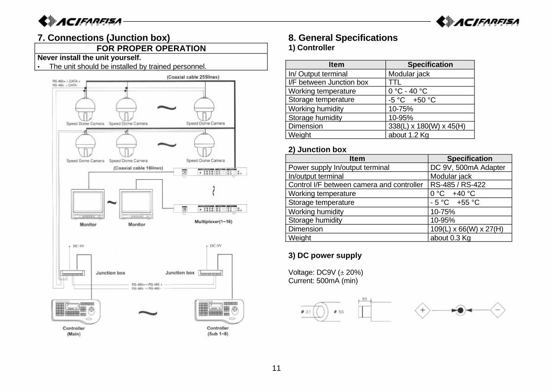
7. Connections (Junction box)FOR PROPER OPERATION
Never install the unit yourself.• The unit should be installed by trained personnel.
8. General Specifications1) Controller
Item SpecificationIn/ Output terminal Modular jackI/F between Junction box TTLWorking temperature 0 °C - 40 °CStorage temperature -5 °C ∼ +50 °CWorking humidity 10-75%Storage humidity 10-95%Dimension 338(L) x 180(W) x 45(H)Weight about 1.2 Kg
2) Junction boxItem Specification
Power supply In/output terminal DC 9V, 500mA AdapterIn/output terminal Modular jackControl I/F between camera and controller RS-485 / RS-422Working temperature 0 °C ∼ +40 °CStorage temperature - 5 °C ∼ +55 °CWorking humidity 10-75%Storage humidity 10-95%Dimension 109(L) x 66(W) x 27(H)Weight about 0.3 Kg
3) DC power supply
Voltage: DC9V (± 20%)Current: 500mA (min)
12
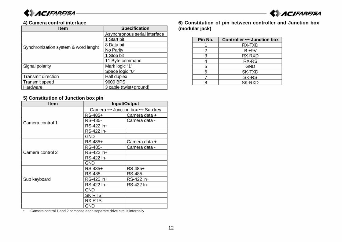
4) Camera control interfaceItem Specification
Asynchronous serial interface1 Start bit8 Data bitNo Parity1 Stop bit
Synchronization system & word lenght
11 Byte commandSignal polarity Mark logic “1”
Space logic “0”Transmit direction Half duplexTransmit speed 9600 BPSHardware 3 cable (twist+ground)
5) Constitution of Junction box pinItem Input/Output
Camera Ö Junction box Ö Sub keyRS-485+ Camera data +RS-485- Camera data -RS-422 In+RS-422 In-
Camera control 1
GNDRS-485+ Camera data +RS-485- Camera data -RS-422 In+RS-422 In-
Camera control 2
GNDRS-485+ RS-485+RS-485- RS-485-RS-422 In+ RS-422 In+RS-422 In- RS-422 In-
Sub keyboard
GNDSK RTSRX RTSGND
• Camera control 1 and 2 compose each separate drive circuit internally
6) Constitution of pin between controller and Junction box(modular jack)
Pin No. Controller ÖÖ Junction box1 RX-TXD2 B +9V3 RX-RXD4 RX-RS5 GND6 SK-TXD7 SK-RS8 SK-RXD

13
9. Quick ReferenceFunction
inputOperation FunctionMain Sub
[Keypad 1-255]+[CAM] Select camera � �Power supply ON + [SET] First stage controller setting � �
[SET]
[SET]+[J.S Stop]+[Keypad 1-64]+[PST][Preset No]+[PST][CLR+3sec.]+[Keypad 1-64]+[PST]+[ENT][CLR+3sec]+[PST]+[ENT]
Start set mode
Input and set the preset pointMove to preset pointPartial deletion of presetWhole deletion of preset
� �
[SET]+[SlWING][1/2]+[ENT][Keypad 1-64]+ [ENT]+[Keypad 1-64]+[ENT][Keypad 1-127]+[ENT][Keypad 1-64]+[ENT][1I2]+[SWING][SWING]/Joystick
Start set swing modeSelect of pan or tilt swingSet up of two preset point
Set up of swing speedSet up of stop timeStart pan or tilt swingStop swing
� �
[SET]+[GROUP][Keypad 1-6]+[ENT][Keypad 1-64]+[ENT][Keypad 1-64]+[ENT]
[Keypad 1-127]+[ENT][SET][Keypad 1-6]+[GROUP][GROUP]/Joystick
Start set group modeSelect of group numberSelect of preset pointSet up the move speed of groupbetween presetsSet up the dwell time of groupComplete setting of groupStart group surveilianceStop group surveillance
� �
[SET]+[TOUR][Keypad 1-6]+[ENT]� repeat[SET][TOUR][TOUR]/Joystick
Start set tour modeSet up tourEnding of setting up TourStart tour surveillanceStop tour surveillance
� �
[MENU][1]+[MENU][F/F]/Joystick[F/N]
Start menu modeMark of OSD MenuOSD Menu enterOSD Menu escape
� �
FunctioninputOperation Function
Main Sub
[2]+[MENU]+[ON/OFF] Set motion detect ON or OFF �
[3]+[MENU]+[ON/OFF] Place of detection display ON/OFF �
[4]+[MENU]Joystick
[Z/I,Z/O]/[F/F,F/N]
Mode of set up zone size displayedExpansion of zone size (up/down,right/left)Reduction of Zone size (up/down,right/left)
�
[5]+[MENU](Keypad 1-10)+[ENT]
Motion sensitivity control modeMotion sensitivity highest � 10Motion sensitivity lowest � 1
�
[6]+[MENU][keypad 1-64]+[ENT]
Motion preset set up modeMotion preset set up �
[7]+[MENU]+[ON][7]+[MENU]+[OFF]
Spiral function practiceSpiral ending �
[8]+[MENU]t[ON][8]+[MENU]+[OFF]
P/T/Z Trace practiceP/T/Z Trace ending �
[9]+[MENU]+[ON][9]+[MENU]+[OFF]
P/T/Z Trace memorisingDeleting memorised P/T/Z Trace �
[Keypad 1-255]+[CAM]+[10]+[MENU]+[ENT] Reset of chosen camera � �
[20]+[MENU]Joystick up/dow n +[CLR]
LCD brightness modeEnding brightness control � �
[STATUS][STATUS]
Freeze practiceFreeze discharge � �
[1]+[STATUS] Confirmafion of MD set camera �[ALARM][ALARM]
Go into alert modeOut of alert mode �
ACI srl Farfisa IntercomsVia E. Vanoni,3 - 60027 - OSIMO - AN - ItalyTel. (+39) 071 7202038 - Fax (+39) 071 7202037Email: [email protected]://www.acifarfisa.it