ASYMMETRIC TRANSMISSION OF LINEARLY POLAR- · PDF fileASYMMETRIC TRANSMISSION OF LINEARLY...
13
Progress In Electromagnetics Research, Vol. 140, 227–239, 2013 ASYMMETRIC TRANSMISSION OF LINEARLY POLAR- IZED WAVES AND DYNAMICALLY WAVE ROTATION USING CHIRAL METAMATERIAL Furkan Dincer 1 , Cumali Sabah 2, * , Muharrem Karaaslan 3 , Emin Unal 3 , Mehmet Bakir 3 , and Utku Erdiven 4 1 Department of Electrical and Electronics Engineering, Bitlis University, Bitlis 13000, Turkey 2 Department of Electrical and Electronics Engineering, Middle East Technical University — Northern Cyprus Campus, Kalkanli, Guzelyurt, TRNC/Mersin 10, Turkey 3 Department of Electrical and Electronics Engineering, Mustafa Kemal University, Iskenderun, Hatay 31200, Turkey 4 Department of Physics, Cukurova University, Adana 01330, Turkey Abstract—The asymmetric transmission of the linearly polarized waves at normal incidence through the lossy anisotropic chiral structure is demonstrated. The proposed chiral metamaterial structure is composed of bi-layered discontinuous cross-wire-strips, and it is utilized in order to realize polarization rotation. Firstly, the theoretical relations between the incident polarization and the polarization rotation are derived using transmission matrices. Secondly, a strong and dynamically asymmetric transmission of linearly polarized electromagnetic wave through the chiral metamaterial has been demonstrated for microwave region, both by simulation and experimentally. The experiment results are in good agreement with the simulation ones. It can be seen from the results that the proposed chiral metamaterial structure can be used to design novel polarization control devices for several frequency regions. Received 6 May 2013, Accepted 26 May 2013, Scheduled 31 May 2013 * Corresponding author: Cumali Sabah ([email protected]).
Transcript of ASYMMETRIC TRANSMISSION OF LINEARLY POLAR- · PDF fileASYMMETRIC TRANSMISSION OF LINEARLY...

Progress In Electromagnetics Research, Vol. 140, 227–239, 2013
ASYMMETRIC TRANSMISSION OF LINEARLY POLAR-IZED WAVES AND DYNAMICALLY WAVE ROTATIONUSING CHIRAL METAMATERIAL
Furkan Dincer1, Cumali Sabah2, *, Muharrem Karaaslan3,Emin Unal3, Mehmet Bakir3, and Utku Erdiven4
1Department of Electrical and Electronics Engineering, BitlisUniversity, Bitlis 13000, Turkey
2Department of Electrical and Electronics Engineering, MiddleEast Technical University — Northern Cyprus Campus, Kalkanli,Guzelyurt, TRNC/Mersin 10, Turkey
3Department of Electrical and Electronics Engineering, Mustafa KemalUniversity, Iskenderun, Hatay 31200, Turkey
4Department of Physics, Cukurova University, Adana 01330, Turkey
Abstract—The asymmetric transmission of the linearly polarizedwaves at normal incidence through the lossy anisotropic chiralstructure is demonstrated. The proposed chiral metamaterial structureis composed of bi-layered discontinuous cross-wire-strips, and it isutilized in order to realize polarization rotation. Firstly, the theoreticalrelations between the incident polarization and the polarizationrotation are derived using transmission matrices. Secondly, astrong and dynamically asymmetric transmission of linearly polarizedelectromagnetic wave through the chiral metamaterial has beendemonstrated for microwave region, both by simulation andexperimentally. The experiment results are in good agreement withthe simulation ones. It can be seen from the results that the proposedchiral metamaterial structure can be used to design novel polarizationcontrol devices for several frequency regions.
Received 6 May 2013, Accepted 26 May 2013, Scheduled 31 May 2013* Corresponding author: Cumali Sabah ([email protected]).

228 Dincer et al.
1. INTRODUCTION
The concept of metamaterials (MTMs) has achieved a remarkableimportance due to their unusual properties different from anyconventional materials [1–9]. These materials are artificial structuresthat can be designed to show specific electromagnetic (EM) propertiesnot commonly found in nature. The first metamaterial is fabricatedin 2000 by Smith and Kroll [10] with periodically arranged inclusionscomposed of a split ring resonator and wire structures. MTMs providemany interesting applications, such as super lens [11], cloaking [12],and negative refraction [13], etc.
The motivation of this study is to investigate the asymmetricfeature of chiral MTMs. Chirality yields a cross-coupling betweenthe electric and magnetic fields, and therefore right- and left-handcircularly polarized waves possess different transmission coefficients.Chiral MTMs do not exhibit any mirror symmetry. They cannot bebrought into congruence with its mirror image unless they are liftedoff the substrate. So, these issues are potentially useful to manipulatethe polarization states of EM waves [14–23].
Many studies focuse on asymmetric transmission through MTMsin two opposite directions. Fedotov et al. [20] outlined that asymmetricphenomenon requires presence of simultaneous planar chirality andanisotropy in the structure and it involves no change in the direction oftransmitted waves. This asymmetric transmission is irrelevant to thenon-reciprocity of the Faraday effect in magneto-optical media [21].Kang et al. [21] studied the relationship among the elements oftransmission matrix, which allows asymmetrical transmission forlinearly polarized EM wave. In 2011, Plum et al. [22] observedthe asymmetric transmission in any lossy periodically structuredplane for oblique incidence. In 2013, Cheng et al. [4] studied adouble-layer split-ring resonator structure (chiral MTM) to obtaingiant circular dichroism with asymmetric transmission. In addition,chiral symmetry provides asymmetric transmission and reflection ofcircularly polarized radiation penetrating the structure from oppositesides. The asymmetric transmission has an important role in manyapplications such as polarization conversion [2], transmission filter [2],etc.
In this paper, we theoretically and experimentally analyzed theasymmetric transmission and polarization rotation of bi-layered anddiscontinuous cross-wire-strips (CWSs). The proposed design exhibitsdirectional selectivity, which appears during the transmission throughchiral MTM slab at microwave frequencies. Also, the structure candynamically control to the polarization rotation of the EM wave.

Progress In Electromagnetics Research, Vol. 140, 2013 229
Besides, it can easily be retailored for the millimeter wave and opticalfrequency regions.
2. THEORETICAL ANALYSIS
Chiral MTMs with the exhibition of cross-coupling and cross-polarization conversion generally result in asymmetric transmission forforward and backward propagation of circularly polarized waves overcertain frequency ranges. This asymmetric transmission provides acertain difference between the polarization states of the wave appliedin opposite sides. For the theoretical analysis, we consider an incomingplane wave that propagates in +z direction with the time dependenceof e−iωt which is suppressed throughout this work [23–26];
Ei (r, t) =(
Ex
Ey
)eikz (1)
with angular frequency ω, wave vector k, and complex amplitudesEx and Ey. To understand polarization conversion, transmission(T ) matrix expression can be applied for the given electric field asfollows [23–26];
Et (r, t) =(
Tx
Ty
)eikz (2)
It is assumed that the medium is symmetrically embedded in dielectricmedium (e.g., in vacuum). The T -matrix relates the complexamplitudes of the incident field to that of the transmitted field:(
Tx
Ty
)=
(Txx Txy
Tyx Tyy
)(Ex
Ey
)= T f
lin
(Ex
Ey
)(3)
The indices f and lin indicate propagation in forward directionand a special linear base with base vectors parallel to the coordinateaxes, i.e., decomposing the incident wave-into x and y polarizedcomponents. The transmitted wave in x and y directions are Txx
and Tyx , respectively. Circularly polarized transmitted waves can beretrieved from the linear transmission coefficients Txx and Tyx as [21–28];
T± = Txx ± iTyx (4)
Four circular transmission coefficients T++, T−+, T+−, and T−−can be calculated from the transmission and reflection coefficientsof linearly polarized waves using the following equation in ±zdirection [21–28];
T fcirc =
(T++ T+−T−+ T−−
)& T b
circ =(
T++ T−+
T+− T−
)(5)

230 Dincer et al.
If the propagation is along −z direction, the equations become [21, 24];(
T++ T+−T−+ T−−
)
=12
(Txx + Tyy + i(Txy − Tyx ) Txx − Tyy + i(Txy + Tyx )Txx − Tyy − i(Txy + Tyx ) Txx + Tyy − i(Txy − Tyx )
)(6)
The asymmetric transmission of the linearly and circularlypolarized waves is commonly characterized by a parameter of ∆. Thisparameter is defined as the difference between the transmittancesin +z and −z directions. It can be used to represent the degreeof asymmetric transmission. For linearly and circularly polarizedwaves, the asymmetric transmission parameter ∆ is defined as ∆(x)
lin =|Tyx |2 − |Txy |2 = −∆(y)
lin , ∆(+)circ = |T−+|2 − |T+−|2 = −∆(y)
circ [21–26].From Eqs. (3)–(6), it can be found that the asymmetric transmissionfor linear polarization can only be realized when the following conditionis satisfied as |Tyx | 6= |Txy | ∩ Txx = Tyy [21]. Planar MTMs alwaysprovide mirror symmetry in the propagation direction. Therefore, thecomponents of the transmission matrix always support Txy = Tyx .However, hybridized MTMs cause to break the mirror symmetry ofthe MTM structure in the propagation direction [21–23].
In addition, the polarization conversion features of the chiralMTM structures cause to change of polarization state of waves whenpropagating through the structure. This can be defined as opticalactivity for chiral structures. When a linearly polarized EM wavepropagates in a medium, the azimuth of polarization plane rotatesclockwise or counter-clockwise depending on the handedness of thematerial. This phenomenon provides the optical activity. These arethe additional beneficial features of the chiral MTM structures.
3. DESIGN, SIMULATION, AND EXPERIMENT
The designed structure consists of bi-layered and discontinuous CWSstructures (metallic part). The mentioned metallic part is placed onthe front- and back-side of a host dielectric substrate and the overallstructure (substrate with the metallic part) will provide asymmetrictransmission for linearly polarized EM waves. Besides, the proposedstructure can also provide asymmetry by changing the dimensions ofCWSs such as length of and distances between the strips.
FR4 dielectric substrate is chosen as a host material with athickness of a4 = 1.6 mm, relative permittivity of 4.2, and loss tangentof 0.02. CWSs are made of copper with a thickness of 0.036mm andthe conductivity of 5.8 × 10⁷ S/m. Figure 1 shows the structure in

Progress In Electromagnetics Research, Vol. 140, 2013 231
(a) (b) (c)
Figure 1. Bi-layered and discontinuous CWSs. (a) Dimensions ofthe unit-cell. (b) Unit cell with open add space boundary conditions.(c) Picture of the sample.
Figure 2. Schematics of the measurement method in theexperiment [29].
detail. Figure 1(a) shows the schematic diagram of the unit cell. Theline-width and height of the metallic strips are a2 = 0.25 mm anda1 = 14 mm, respectively. The gap in CWSs is a3 = 0.25 mm. Theoffsets with respect to the origin are 45◦ for the front CWSs and 75◦for the back CWSs, respectively.
The structure was simulated and analyzed with a commercial full-wave EM solver (CST Microwave Studio based on finite integrationtechnique). Unit cell and open add space boundary conditions areused in the simulation as shown in Figure 1(b). The fabricated samplewith the dimension of 240 × 240mm2 is shown in Figure 1(c). Theunit cell has periodicity of a5 = a6 = 16 mm along x- and y-directions.CWSs have strong feature to rotate polarization of EM wave due tothe electric and magnetic coupling between multi cross-strips.
The numerical simulations are analyzed then to determinereflection and transmission properties of the proposed structure.Figure 2 shows the schematic experimental setup for the measurementof Txx and Tyx . The experimental measurement setup consists ofan Agilent-E5071B ENA RF vector network analyzer (VNA) and

232 Dincer et al.
microwave horn antennas. Firstly, free space measurement withoutthe chiral structure is carried out and this measurement used as thecalibration data for VNA. Secondly, the structure is then inserted intothe experimental measurement setup and transmission measurementsare performed. The distance between the horn antennas and chiralslab is kept sufficiently large to eliminate near-field effects.
4. NUMERICAL AND EXPERIMENTAL RESULTS
In order to investigate the frequency response of the chiral MTM, thestructure is designed and simulated with respect to the plane wavespropagating along (+z)and (−z) directions. Then, to obtain linearT -matrix coefficients of the slab, Txx and Tyx are obtained from thesimulations and experiments when the incident wave is x-polarized.After that, linear transmission Txy and Tyy are obtained for y-polarizedincident wave, too.
We measured both the forward and backward transmissioncoefficients. Figure 3 shows the measurement and simulation results ofT-matrix elements (Txx , Txy , Tyx , Tyy) of the slab for propagations offorward (+z) and backward (−z) directions. The experimental resultsare in good agreement with the numerical simulations as shown. Itcan be seen that the co-polarized transmission Tyy has a resonant peakand reaches its maximum value of around 0.66 at the frequency off = 6.91GHz. Also, the simulation and experimental results showthat Txx and Tyy are almost equal to each other. Cross-polarized
Figure 3. Simulated and measured transmission spectra of T -matrixelements (Txx , Txy , Tyx , Tyy) of the slab for propagations of +z(forward) and −z (backward) directions.
Progress In Electromagnetics Research, Vol. 140, 2013 233
transmission Txy and Tyx reduce to its minimum value of about 0.01at the frequency of f = 4.8GHz.
According to the simulated and experimental results (and Eq. (8)too), asymmetry in the transmission for the linear polarization maybe acquired when the propagation direction is reversed. This changeconfirms the presence of circular conversion of dichroism T+− 6= T−+.However, the conventional optical activity is independent from thepropagation direction (T+− = T−+). Also, replacing the planar chiralmetamaterial with its mirror image reverses the asymmetry of circulartransmission. Therefore, when handedness of the polarization state ischanged, the sign of the transmission asymmetry will be reversed forasymmetric planar chiral MTMs. Moreover, it can be seen that whenthe propagation direction is reversed, the cross-polarization elementsTxy and Tyx interchange with each other (Figure 3). Normally, anyplanar MTM always has mirror symmetry in the propagation direction.As studied in the theoretical analysis, Txx and Tyy are exactly equal,which ensures zero asymmetric transmission of circular polarizationwaves for chiral MTMs that is satisfied both in the simulation andexperimental results (Figure 3) [16–26].
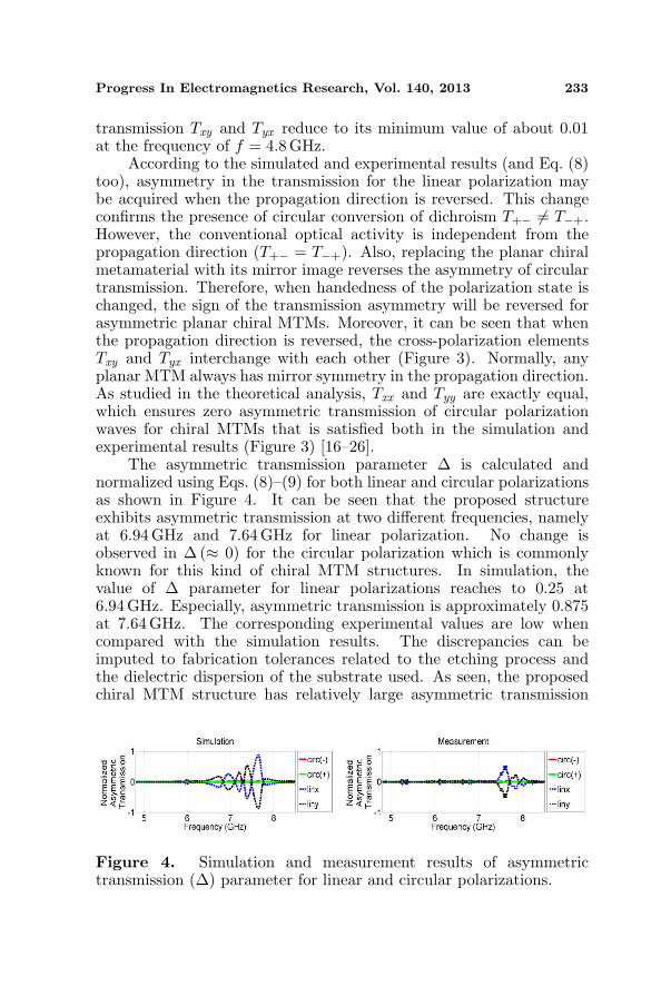
The asymmetric transmission parameter ∆ is calculated andnormalized using Eqs. (8)–(9) for both linear and circular polarizationsas shown in Figure 4. It can be seen that the proposed structureexhibits asymmetric transmission at two different frequencies, namelyat 6.94 GHz and 7.64GHz for linear polarization. No change isobserved in ∆ (≈ 0) for the circular polarization which is commonlyknown for this kind of chiral MTM structures. In simulation, thevalue of ∆ parameter for linear polarizations reaches to 0.25 at6.94GHz. Especially, asymmetric transmission is approximately 0.875at 7.64GHz. The corresponding experimental values are low whencompared with the simulation results. The discrepancies can beimputed to fabrication tolerances related to the etching process andthe dielectric dispersion of the substrate used. As seen, the proposedchiral MTM structure has relatively large asymmetric transmission
Figure 4. Simulation and measurement results of asymmetrictransmission (∆) parameter for linear and circular polarizations.

234 Dincer et al.
parameter for linear polarization. This feature can also be observedfor different frequencies.
After obtaining transmission data, the retrieval study forthe chirality parameter, κ, is applied. Complex chirality canbe obtained directly from transmission coefficients as Re(κ) =[arg(T+)−arg(T−)+2mπ]
2k0d , Im(κ) = ln |TL|−ln|TR|2k0d , where k0 is the wave
number in vacuum, d the thickness of the structure, and m isinteger [27–31]. Figure 5 shows the simulation and measurement resultsfor the chirality parameter. The chirality is large, κ = ±6.1 (4.7) atthe frequency of 8.36GHz for the simulation (measurement) results.Furthermore, the chirality is larger, κ = ±7.7 at the frequency off = 6.46GHz for the simulation. The corresponding positive chiralityvalue for the frequency span of 6.1GHz and 6.5GHz is approximately6 for the measurement. However, the negative value is small whencompared with the simulation and reaches to −2, for the measurement.
In order to check the performance of the designed structure basedon chirality, the Figure of Merit (FOM = |Re(κ)/Im(κ)|) calculationis performed and the result is shown in Figure 6. As seen, FOM valuesat and around the resonances of 6.46GHz and 8.36GHz (when thechirality changes significantly) are very large. This implies very goodperformance of the proposed structure.
Now, the effect of the change in the dimensions of CWSs onthe chirality is investigated and the results are shown in Figure 7.
Figure 5. Simulated and measured chirality parameter for fabricatedchiral MTM structure.
Figure 6. Figure of merit of the proposed chiral MTM.
Progress In Electromagnetics Research, Vol. 140, 2013 235
(a) (b)
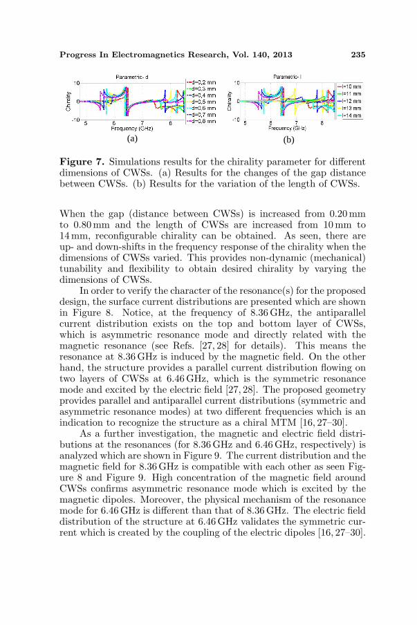
Figure 7. Simulations results for the chirality parameter for differentdimensions of CWSs. (a) Results for the changes of the gap distancebetween CWSs. (b) Results for the variation of the length of CWSs.
When the gap (distance between CWSs) is increased from 0.20mmto 0.80mm and the length of CWSs are increased from 10 mm to14mm, reconfigurable chirality can be obtained. As seen, there areup- and down-shifts in the frequency response of the chirality when thedimensions of CWSs varied. This provides non-dynamic (mechanical)tunability and flexibility to obtain desired chirality by varying thedimensions of CWSs.
In order to verify the character of the resonance(s) for the proposeddesign, the surface current distributions are presented which are shownin Figure 8. Notice, at the frequency of 8.36GHz, the antiparallelcurrent distribution exists on the top and bottom layer of CWSs,which is asymmetric resonance mode and directly related with themagnetic resonance (see Refs. [27, 28] for details). This means theresonance at 8.36GHz is induced by the magnetic field. On the otherhand, the structure provides a parallel current distribution flowing ontwo layers of CWSs at 6.46 GHz, which is the symmetric resonancemode and excited by the electric field [27, 28]. The proposed geometryprovides parallel and antiparallel current distributions (symmetric andasymmetric resonance modes) at two different frequencies which is anindication to recognize the structure as a chiral MTM [16, 27–30].
As a further investigation, the magnetic and electric field distri-butions at the resonances (for 8.36GHz and 6.46GHz, respectively) isanalyzed which are shown in Figure 9. The current distribution and themagnetic field for 8.36GHz is compatible with each other as seen Fig-ure 8 and Figure 9. High concentration of the magnetic field aroundCWSs confirms asymmetric resonance mode which is excited by themagnetic dipoles. Moreover, the physical mechanism of the resonancemode for 6.46GHz is different than that of 8.36GHz. The electric fielddistribution of the structure at 6.46 GHz validates the symmetric cur-rent which is created by the coupling of the electric dipoles [16, 27–30].

236 Dincer et al.
(a) (b)
Figure 8. The simulated surface current distribution (a) at themagnetic resonance of 8.36GHz and (b) at the electric resonancefrequency of 6.46GHz.
(a) (b)
Figure 9. (a) Magnetic field distribution of the structure at theresonant frequency of 8.36GHz and (b) electric field distribution ofthe structure at the resonant frequency of 6.46GHz.
5. CONCLUSIONS
Theoretical and experimental analysis of a chiral MTM structurecomposed of a dielectric substrate and bi-layered and discontinuousCWSs for asymmetric transmission is investigated in detail. Theproposed structure can generate an asymmetric EM wave transmissionfor linear polarization. In addition, the structure has flexible,tunability, and easy fabrication features. The angle, length, width, anddistance of the wire strips can be retailored for desired EM responsesuch as asymmetric transmission (as mentioned), different chiralityparameters, and so on. These controllable features can also providesignificant optical activity because of the internal property of chiralmetamaterial. Besides, the structure’s polarization tunability offersan additional degree of freedom for the polarization control in whichthe strong optical activity can be utilized to design new microwave

Progress In Electromagnetics Research, Vol. 140, 2013 237
rotator or polarization control devices. This is confirmed with the goodagreement between the simulated and experimental results. Note thatthe design of novel devices based on the findings of the present studyas well as the study itself can easily be extended for different frequencyregimes too.
Therefore, bi-layered and discontinuous CWSs-shaped topologylends itself as a useful alternative to the well-known chiral MTMstructures which provides asymmetric transmission and opens a wayto design new devices with very large-chirality to be used in severalpotential applications. Particularly, the structure can be utilizedto design more efficient circulators, configurable polarization rotator,wave-plates and sensors.
REFERENCES
1. Sabah, C., H. T. Tastan, F. Dincer, K. Delihacioglu, M. Karaaslan,and E. Unal, “Transmission tunneling through the multi-layer double-negative and double-positive slabs,” Progress InElectromagnetics Research, Vol. 138, 293–306, 2013.
2. Sabah, C. and H. G. Roskos “Design of a terahertz polarizationrotator based on a periodic sequence of chiral metamaterial anddielectric slabs,” Progress In Electromagnetics Research, Vol. 124,301–314, 2012.
3. Dong, J. F., “Surface wave modes in chiral negative refractiongrounded slab waveguides,” Progress In Electromagnetics Re-search, Vol. 95, 153–166, 2009.
4. Cheng, Y., Y. Nie, L. Wu, and R. Gong, “Giant circular dichroismand negative refractive index of chiral metamaterial based on split-ring resonators,” Progress In Electromagnetics Research, Vol. 138,421–432, 2013.
5. Burlak, G., “Spectrum of Cherenkov radiation in dispersivemetamaterials with negative refraction index,” Progress InElectromagnetics Research, Vol. 132, 149–158, 2012.
6. Da, H. and C. W. Qiu, “Graphene-based photonic crystal to steergiant Faraday rotation,” Appl. Phys. Lett., Vol. 100, 241106, 2012.
7. Faruque, M. R. I., M. T. Islam, and N. Misran, “Design analysisof new metamaterial for EM absorption reduction,” Progress InElectromagnetics Research, Vol. 124, 119–135, 2012.
8. Chen, H. S., L. Huang, X. X. Cheng, and H. Wang, “Magneticproperties of metamaterial composed of closed rings,” Progress InElectromagnetics Research, Vol. 115, 317–326, 2011.
238 Dincer et al.
9. Karaaslan, M. and F. Karadag, “Adjustable sub-wavelengthwaveguide by uniaxially designed artificial magnetic media,”Optoelectron. Adv. Mat., Vol. 3, 578–580, 2009.
10. Smith, D. R. and N. Kroll, “Negative refraction index in left-handed materials,” Phys. Rev. Lett., Vol. 85. 2933–2936, 2000.
11. Fang, N., H. Lee, C. Sun, and X. Zhang, “Sub-diffraction-limitedoptical imaging with a silver superlens,” Science, Vol. 308, 534–537, 2005.
12. Pendry, J. B., D. Schurig, and D. R. Smith, “Controllingelectromagnetic fields,” Science, Vol. 312, 1780–1782, 2006.
13. Shelby, R. A., D. R. Smith, and S. Schultz, “Experimentalverification of a negative index of refraction,” Science, Vol. 292,77–79, 2001.
14. He, Y., J. Shen, and S. He, “Consistent formalism forthe momentum of electromagnetic waves in lossless dispersivemetamaterials and the conservation of momentum,” Progress InElectromagnetics Research, Vol. 116, 81–106, 2011.
15. Zhang, F., V. Sadaune, L. Kang, Q. Zhao, J. Zhou, andD. Lippens, “Coupling effect for dielectric metamaterial dimer,”Progress In Electromagnetics Research, Vol. 132, 587–601, 2012.
16. Zhao, R., L. Zhang, J. Zhou, T. Koschny, and C. M. Soukoulis,“Conjugated gammadion chiral metamaterial with uniaxial opticalactivity and negative refractive index,” Phys. Rev. B, Vol. 83,035105-4, 2011.
17. Sabah, C. and S. Uckun, “Multilayer system of Lorentz/Drudetype metamaterials with dielectric slabs and its application toelectromagnetic filters,” Progress In Electromagnetics Research,Vol. 91, 349–364, 2009.
18. Iwanaga, M., “First-principle analysis for electromagnetic eigenmodes in an optical metamaterial slab,” Progress In Electromag-netics Research, Vol. 132, 129–148, 2012.
19. Yan, S. and G. A. E. Vandenbosch, “Increasing the NRIbandwidth of dielectric sphere-based metamaterials by coating,”Progress In Electromagnetics Research, Vol. 132, 1–23, 2012.
20. Fedotov, V. A., P. L. Mladyonov, S. L. Prosvirnin, A. V. Ro-gacheva, Y. Chen, and N. I. Zheludev, “Asymmetric propagationof electromagnetic waves through a planar chiral structure,” Phys.Rev. Lett., Vol. 97, 167401-4, 2006.
21. Kang, M., J. Chen, H.-X. Cui, Y. Li, and H.-T. Wang,“Asymmetric transmission for linearly polarized electromagneticradiation,” Opt. Express, Vol. 19, 8347–8356, 2011.

Progress In Electromagnetics Research, Vol. 140, 2013 239
22. Plum, E., V. A. Fedotov, and N. I. Zheludev, “Asymmetrictransmission: A generic property of two-dimensional periodicpatterns,” J. Optics, Vol. 13, 024006-6, 2011.
23. Guo, W., L. He, B. Li, T. Teng, and X. W. Sun, “A widebandand dual-resonant terahertz metamaterial using a modified SRRstructure,” Progress In Electromagnetics Research, Vol. 134, 289–299, 2013.
24. Menzel, C., C. Helgert, C. Rockstuhl, and E. B. Kley,A. Tunnermann, T. Pertsch, and F. Lederer, “Asymmetrictransmission of linearly polarized light at optical metamaterials,”Phys. Rev. Lett., Vol. 104, 253902-4, 2010.
25. Huang, C., Y. Feng, J. Zhao, Z. Wang, and T. Jiang, “Asymmetricelectromagnetic wave transmission of linear polarization viapolarization conversion through chiral metamaterial structures,”Phys. Rev. B, Vol. 85, 195131-5, 2012.
26. Huang, C., J. Zhao, T. Jiang, and Y. Feng, “Asymmetrictransmission of linearly polarized electromagnetic wave throughchiral metamaterial structure,” Journal of Electromagnetic Wavesand Applications, Vol. 26, Nos. 8–9, 1192–1202, 2012.
27. Wang, B., J. Zhou, T. Koschny, M. Kafesaki, and C. M. Soukolis,“Chiral metamaterials: Simulations and experiments,” Journal ofOptics A: Pure and Applied Optics, Vol. 11, 114003-13, 2009.
28. Zhou, J., J. Dong, B. Wang, T. Koschny, M. Kafesaki, andC. M. Soukoulis, “Negative refractive index due to chirality,” Phys.Rev. B, Vol. 79, 121104-4, 2009.
29. Li, Z., M. Mutlu, and E. Ozbay, “Chiral metamaterials: Fromoptical activity and negative refractive index to asymmetrictransmission,” J. Optics, Vol. 15, 023001, 2013.
30. Li, Z., H. Caglayan, E. Colak, J. Zhou, C. M. Soukoulis, andE. Ozbay, “Coupling effect between two adjacent chiral structurelayers,” Opt. Express, Vol. 18, 5375–5383, 2010.
31. Li, Z., R. Zhao, T. Koschny, M. Kafesaki, K. B. Alici,E. Colak, H. Caglayan, E. Ozbay, and C. M. Soukoulis, “Chiralmetamaterials with negative refractive index based on four ‘U’split ring resonators,” Appl. Phys. Lett., Vol. 97, 081901-3, 2010.