ASTRA Owner's Manual - opelegypt.net · 9/8/2016 · Adaptive cruise control is active. Adaptive...
295
ASTRA Owner's Manual
-
Upload
hoangkhanh -
Category
Documents
-
view
227 -
download
0
Transcript of ASTRA Owner's Manual - opelegypt.net · 9/8/2016 · Adaptive cruise control is active. Adaptive...
ASTRAOwner's Manual

Introduction .................................... 2In brief ............................................ 6Keys, doors and windows ............ 22Seats, restraints ........................... 39Storage ........................................ 61Instruments and controls ............. 73Lighting ...................................... 116Climate control ........................... 129Driving and operating ................. 139Vehicle care ............................... 200Service and maintenance .......... 254Technical data ........................... 257Customer information ................ 280Index .......................................... 288
Contents
2 Introduction
Introduction
Introduction 3
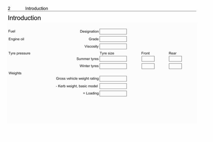
Vehicle specific dataPlease enter your vehicle's data onthe previous page to keep it easilyaccessible. This information isavailable in the sections "Service andmaintenance" and "Technical data"as well as on the identification plate.
IntroductionYour vehicle is a designedcombination of advanced technology,safety, environmental friendlinessand economy.This Owner's Manual provides youwith all the necessary information toenable you to drive your vehiclesafely and efficiently.Make sure your passengers areaware of the possible risk of accidentand injury which may result fromimproper use of the vehicle.You must always comply with thespecific laws and regulations of thecountry that you are in. These lawsmay differ from the information in thisOwner's Manual.Disregarding the description given inthis manual may affect your warranty.
When this Owner's Manual refers to aworkshop visit, we recommend yourOpel Service Partner. For gasvehicles we recommend an OpelRepairer authorised for servicing gasvehicles.All Opel Service Partners providefirst-class service at reasonableprices. Experienced mechanicstrained by Opel work according tospecific Opel instructions.The customer literature pack shouldalways be kept ready to hand in thevehicle.
Using this manual● This manual describes all options
and features available for thismodel. Certain descriptions,including those for display andmenu functions, may not apply toyour vehicle due to modelvariant, country specifications,special equipment oraccessories.
● The "In brief" section will give youan initial overview.
● The table of contents at thebeginning of this manual andwithin each section shows wherethe information is located.
● The index will enable you tosearch for specific information.
● This Owner's Manual depicts left-hand drive vehicles. Operation issimilar for right-hand drivevehicles.
● The Owner's Manual uses theengine identifier code. Thecorresponding sales designationand engineering code can befound in the section "Technicaldata".
● Directional data, e.g. left or right,or front or back, always relate tothe direction of travel.
● Displays may not support yourspecific language.
● Display messages and interiorlabelling are written in boldletters.
4 Introduction
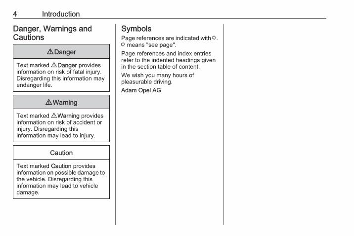
Danger, Warnings andCautions
9 Danger
Text marked 9 Danger providesinformation on risk of fatal injury.Disregarding this information mayendanger life.
9 Warning
Text marked 9 Warning providesinformation on risk of accident orinjury. Disregarding thisinformation may lead to injury.
Caution
Text marked Caution providesinformation on possible damage tothe vehicle. Disregarding thisinformation may lead to vehicledamage.
SymbolsPage references are indicated with 3.3 means "see page".Page references and index entriesrefer to the indented headings givenin the section table of content.We wish you many hours ofpleasurable driving.Adam Opel AG

Introduction 5
6 In brief
In brief
Initial drive information
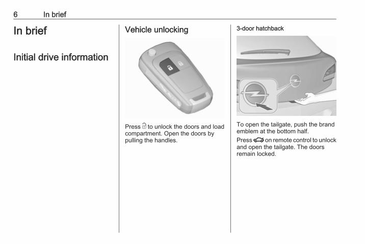
Vehicle unlocking
Press c to unlock the doors and loadcompartment. Open the doors bypulling the handles.
3-door hatchback
To open the tailgate, push the brandemblem at the bottom half.Press x on remote control to unlockand open the tailgate. The doorsremain locked.
In brief 7
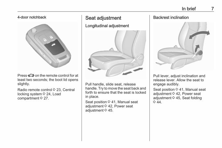
4-door notchback
Press x on the remote control for atleast two seconds; the boot lid opensslightly.Radio remote control 3 23, Centrallocking system 3 24, Loadcompartment 3 27.
Seat adjustmentLongitudinal adjustment
Pull handle, slide seat, releasehandle. Try to move the seat back andforth to ensure that the seat is lockedin place.Seat position 3 41, Manual seatadjustment 3 42, Power seatadjustment 3 45.
Backrest inclination
Pull lever, adjust inclination andrelease lever. Allow the seat toengage audibly.Seat position 3 41, Manual seatadjustment 3 42, Power seatadjustment 3 45, Seat folding3 44.

8 In brief
Seat height
Lever pumping motionup : seat higherdown : seat lower
Seat position 3 41, Manual seatadjustment 3 42, Power seatadjustment 3 45.
Seat inclination
Lever pumping motionup : front end higherdown : front end lower
Seat position 3 41, Manual seatadjustment 3 42, Power seatadjustment 3 45.
Head restraint adjustment
Press release button, adjust height,engage.Head restraints 3 39.
In brief 9
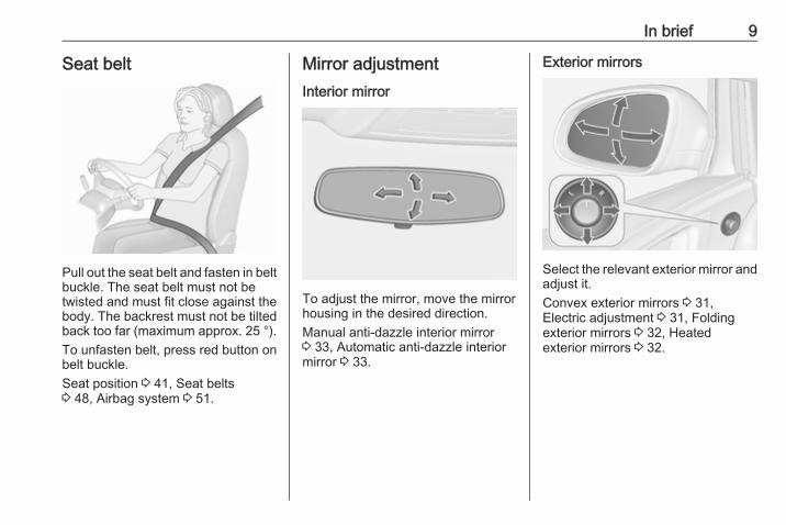
Seat belt
Pull out the seat belt and fasten in beltbuckle. The seat belt must not betwisted and must fit close against thebody. The backrest must not be tiltedback too far (maximum approx. 25 °).To unfasten belt, press red button onbelt buckle.Seat position 3 41, Seat belts3 48, Airbag system 3 51.
Mirror adjustmentInterior mirror
To adjust the mirror, move the mirrorhousing in the desired direction.Manual anti-dazzle interior mirror3 33, Automatic anti-dazzle interiormirror 3 33.
Exterior mirrors
Select the relevant exterior mirror andadjust it.Convex exterior mirrors 3 31,Electric adjustment 3 31, Foldingexterior mirrors 3 32, Heatedexterior mirrors 3 32.
10 In brief
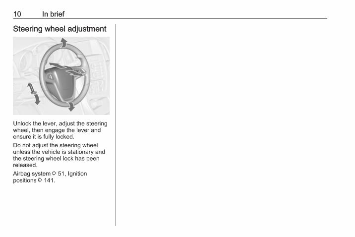
Steering wheel adjustment
Unlock the lever, adjust the steeringwheel, then engage the lever andensure it is fully locked.Do not adjust the steering wheelunless the vehicle is stationary andthe steering wheel lock has beenreleased.Airbag system 3 51, Ignitionpositions 3 141.
In brief 11
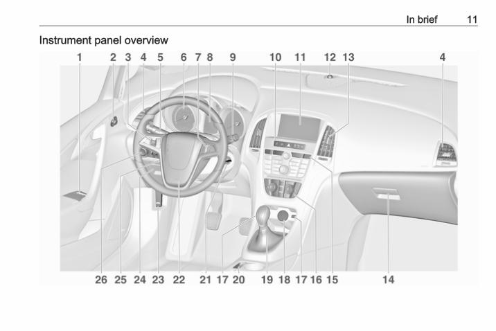
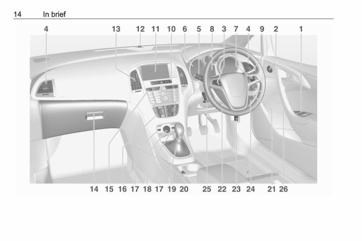
Instrument panel overview

12 In brief
1 Power windows ..................... 342 Exterior mirrors ..................... 313 Cruise control ..................... 159
Speed limiter ....................... 161
Adaptive cruise control ....... 162
Forward collision alert ......... 1694 Side air vents ...................... 1375 Turn and lane-change
signals, headlight flash,low beam and high beam,high beam assist ................. 123
Exit lighting ......................... 127
Parking lights ...................... 124
Buttons for DriverInformation Centre ................ 93
6 Instruments .......................... 817 Steering wheel controls ....... 748 Driver Information Centre ...... 939 Windscreen wiper,
windscreen washersystem, headlight washersystem, rear windowwiper, rear window washersystem ................................... 75
10 Sport mode ........................ 156
Central locking system .......... 24
Fuel selector ......................... 82
Hazard warning flashers .... 123
Control indicator for airbagdeactivation .......................... 87
Control indicator for frontpassenger seat belt ............. 87
Tour mode .......................... 15611 Info-Display .......................... 9712 Anti-theft alarm system
status LED ........................... 2913 Centre air vents .................. 13714 Glovebox .............................. 6115 Traction Control system
(TC) ..................................... 154
Electronic Stability Control(ESC) .................................. 155
Parking assist systems ....... 175
Lane departure warning ..... 187
Eco button for stop-startsystem ................................. 142
Unlock button for boot lid ...... 2716 Climate control system ........ 12917 AUX input, USB input, SD
card slot ................................ 1118 Power outlet .......................... 7919 Selector lever, manual
transmission ....................... 151
Automatic transmission ...... 14720 Electric parking brake ......... 15221 Ignition switch with
steering wheel lock ............ 14122 Horn ..................................... 75
Driver airbag ........................ 5123 Bonnet release lever .......... 20224 Storage compartment,
fuse box ............................. 22625 Steering wheel adjustment . . 7426 Light switch ........................ 116
Headlight rangeadjustment ......................... 119
Front fog lights ................... 124
In brief 13
Rear fog light ...................... 124
Instrument illumination ....... 125
14 In brief
In brief 15
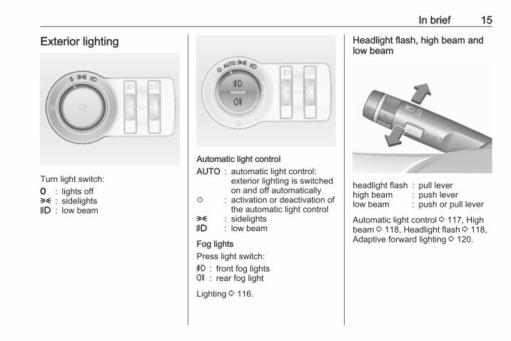
Exterior lighting
Turn light switch:7 : lights off8 : sidelights9 : low beam
Automatic light controlAUTO : automatic light control:
exterior lighting is switchedon and off automatically
m : activation or deactivation ofthe automatic light control
8 : sidelights9 : low beam
Fog lightsPress light switch:> : front fog lightsr : rear fog light
Lighting 3 116.
Headlight flash, high beam andlow beam
headlight flash : pull leverhigh beam : push leverlow beam : push or pull lever
Automatic light control 3 117, Highbeam 3 118, Headlight flash 3 118,Adaptive forward lighting 3 120.
16 In brief
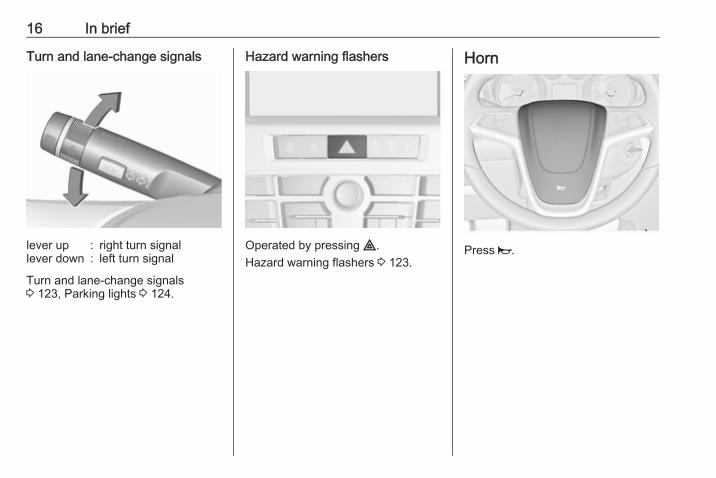
Turn and lane-change signals
lever up : right turn signallever down : left turn signal
Turn and lane-change signals3 123, Parking lights 3 124.
Hazard warning flashers
Operated by pressing ¨.Hazard warning flashers 3 123.
Horn
Press j.
In brief 17
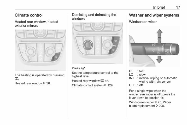
Climate controlHeated rear window, heatedexterior mirrors
The heating is operated by pressingÜ.Heated rear window 3 36.
Demisting and defrosting thewindows
Press V.Set the temperature control to thehighest level.Heated rear window Ü on.Climate control system 3 129.
Washer and wiper systemsWindscreen wiper
HI : fastLO : slowINT : interval wiping or automatic
wiping with rain sensorOFF : off
For a single wipe when thewindscreen wiper is off, press thelever down to position 1x.Windscreen wiper 3 75, Wiperblade replacement 3 208.
18 In brief
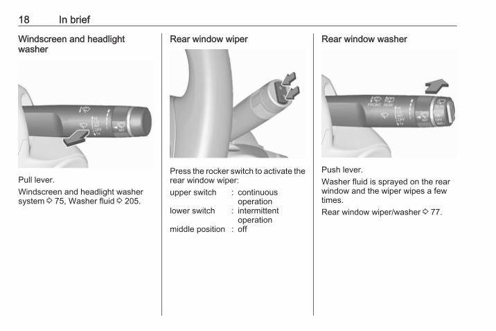
Windscreen and headlightwasher
Pull lever.Windscreen and headlight washersystem 3 75, Washer fluid 3 205.
Rear window wiper
Press the rocker switch to activate therear window wiper:upper switch : continuous
operationlower switch : intermittent
operationmiddle position : off
Rear window washer
Push lever.Washer fluid is sprayed on the rearwindow and the wiper wipes a fewtimes.Rear window wiper/washer 3 77.
In brief 19
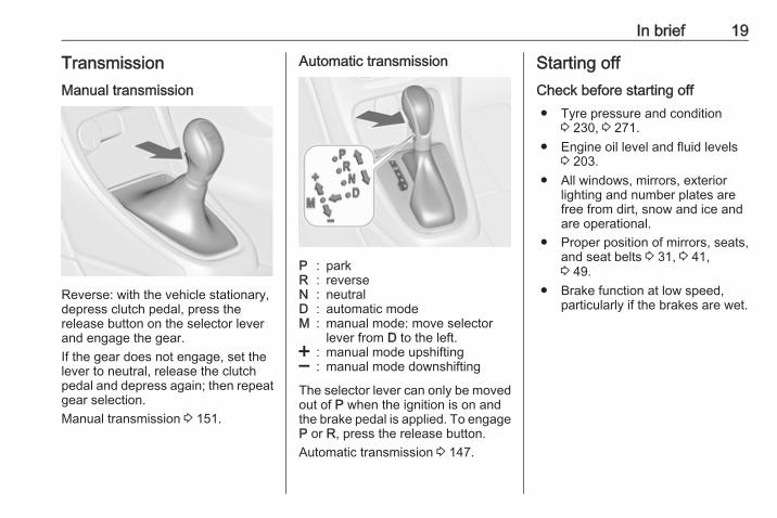
TransmissionManual transmission
Reverse: with the vehicle stationary,depress clutch pedal, press therelease button on the selector leverand engage the gear.If the gear does not engage, set thelever to neutral, release the clutchpedal and depress again; then repeatgear selection.Manual transmission 3 151.
Automatic transmission
P : parkR : reverseN : neutralD : automatic modeM : manual mode: move selector
lever from D to the left.< : manual mode upshifting] : manual mode downshifting
The selector lever can only be movedout of P when the ignition is on andthe brake pedal is applied. To engageP or R, press the release button.Automatic transmission 3 147.
Starting offCheck before starting off● Tyre pressure and condition
3 230, 3 271.● Engine oil level and fluid levels
3 203.● All windows, mirrors, exterior
lighting and number plates arefree from dirt, snow and ice andare operational.
● Proper position of mirrors, seats,and seat belts 3 31, 3 41,3 49.
● Brake function at low speed,particularly if the brakes are wet.
20 In brief
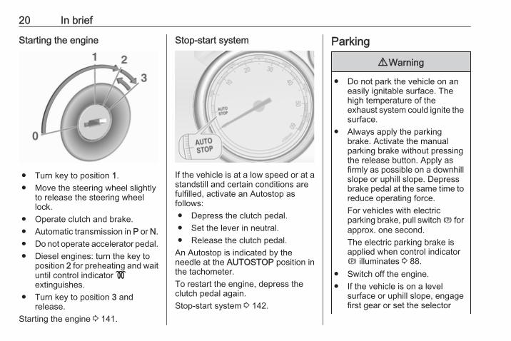
Starting the engine
● Turn key to position 1.● Move the steering wheel slightly
to release the steering wheellock.
● Operate clutch and brake.● Automatic transmission in P or N.● Do not operate accelerator pedal.● Diesel engines: turn the key to
position 2 for preheating and waituntil control indicator !extinguishes.
● Turn key to position 3 andrelease.
Starting the engine 3 141.
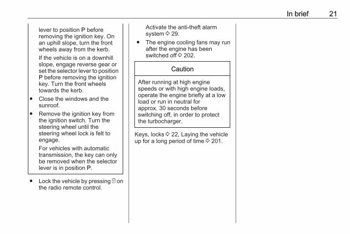
Stop-start system
If the vehicle is at a low speed or at astandstill and certain conditions arefulfilled, activate an Autostop asfollows:● Depress the clutch pedal.● Set the lever in neutral.● Release the clutch pedal.
An Autostop is indicated by theneedle at the AUTOSTOP position inthe tachometer.To restart the engine, depress theclutch pedal again.Stop-start system 3 142.
Parking
9 Warning
● Do not park the vehicle on aneasily ignitable surface. Thehigh temperature of theexhaust system could ignite thesurface.
● Always apply the parkingbrake. Activate the manualparking brake without pressingthe release button. Apply asfirmly as possible on a downhillslope or uphill slope. Depressbrake pedal at the same time toreduce operating force.For vehicles with electricparking brake, pull switch m forapprox. one second.The electric parking brake isapplied when control indicatorm illuminates 3 88.
● Switch off the engine.● If the vehicle is on a level
surface or uphill slope, engagefirst gear or set the selector
In brief 21
lever to position P beforeremoving the ignition key. Onan uphill slope, turn the frontwheels away from the kerb.If the vehicle is on a downhillslope, engage reverse gear orset the selector lever to positionP before removing the ignitionkey. Turn the front wheelstowards the kerb.
● Close the windows and thesunroof.
● Remove the ignition key fromthe ignition switch. Turn thesteering wheel until thesteering wheel lock is felt toengage.For vehicles with automatictransmission, the key can onlybe removed when the selectorlever is in position P.
● Lock the vehicle by pressing e onthe radio remote control.
Activate the anti-theft alarmsystem 3 29.
● The engine cooling fans may runafter the engine has beenswitched off 3 202.
Caution
After running at high enginespeeds or with high engine loads,operate the engine briefly at a lowload or run in neutral forapprox. 30 seconds beforeswitching off, in order to protectthe turbocharger.
Keys, locks 3 22, Laying the vehicleup for a long period of time 3 201.
22 Keys, doors and windows
Keys, doors andwindows
Keys, locks ................................... 22Keys .......................................... 22Car Pass .................................... 23Radio remote control ................. 23Memorised settings ................... 24Central locking system .............. 24Automatic locking ...................... 26Child locks ................................. 26
Doors ........................................... 27Load compartment .................... 27
Vehicle security ............................ 29Anti-theft locking system ........... 29Anti-theft alarm system .............. 29Immobiliser ................................ 31
Exterior mirrors ............................ 31Convex shape ........................... 31Electric adjustment .................... 31Folding mirrors .......................... 32Heated mirrors ........................... 32
Interior mirrors ............................. 33Manual anti-dazzle .................... 33Automatic anti-dazzle ................ 33
Windows ...................................... 33Windscreen ............................... 33Manual windows ........................ 34Power windows ......................... 34Heated rear window .................. 36Sun visors .................................. 36
Roof ............................................. 36Sunroof ...................................... 36Glass panel ............................... 38
Keys, locksKeys
Caution
Do not attach heavy or bulky itemsto the ignition key.
Replacement keysThe key number is specified in theCar Pass or on a detachable tag.The key number must be quotedwhen ordering replacement keys as itis a component of the immobilisersystem.Locks 3 250.The code number of the adapter forthe locking wheel nuts is specified ona card. It must be quoted whenordering a replacement adapter.Wheel changing 3 239.
Keys, doors and windows 23
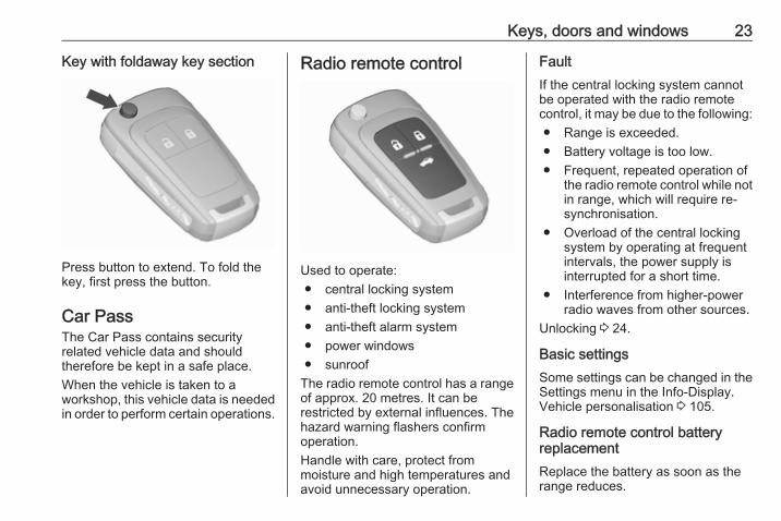
Key with foldaway key section
Press button to extend. To fold thekey, first press the button.
Car PassThe Car Pass contains securityrelated vehicle data and shouldtherefore be kept in a safe place.When the vehicle is taken to aworkshop, this vehicle data is neededin order to perform certain operations.
Radio remote control
Used to operate:● central locking system● anti-theft locking system● anti-theft alarm system● power windows● sunroof
The radio remote control has a rangeof approx. 20 metres. It can berestricted by external influences. Thehazard warning flashers confirmoperation.Handle with care, protect frommoisture and high temperatures andavoid unnecessary operation.
FaultIf the central locking system cannotbe operated with the radio remotecontrol, it may be due to the following:● Range is exceeded.● Battery voltage is too low.● Frequent, repeated operation of
the radio remote control while notin range, which will require re-synchronisation.
● Overload of the central lockingsystem by operating at frequentintervals, the power supply isinterrupted for a short time.
● Interference from higher-powerradio waves from other sources.
Unlocking 3 24.
Basic settingsSome settings can be changed in theSettings menu in the Info-Display.Vehicle personalisation 3 105.
Radio remote control batteryreplacementReplace the battery as soon as therange reduces.
24 Keys, doors and windows
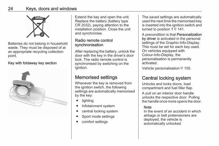
Batteries do not belong in householdwaste. They must be disposed of atan appropriate recycling collectionpoint.
Key with foldaway key section
Extend the key and open the unit.Replace the battery (battery typeCR 2032), paying attention to theinstallation position. Close the unitand synchronise.
Radio remote controlsynchronisationAfter replacing the battery, unlock thedoor with the key in the driver's doorlock. The radio remote control issynchronised by switching on theignition.
Memorised settingsWhenever the key is removed fromthe ignition switch, the followingsettings are automatically memorisedby the key:● lighting● Infotainment system● central locking system● Sport mode settings● comfort settings
The saved settings are automaticallyused the next time the memorised keyis inserted into the ignition switch andturned to position 1 3 141.A precondition is that Personalizationby driver is activated in the personalsettings of the Graphic-Info-Display.This must be set for each key used.On vehicles equipped withColour-Info-Display, thepersonalisation is permanentlyactivated.Vehicle personalisation 3 105.
Central locking systemUnlocks and locks doors, loadcompartment and fuel filler flap.A pull on an interior door handleunlocks the respective door. Pullingthe handle once more opens the door.NoteIn the event of an accident in whichairbags or belt pretensioners aredeployed, the vehicle isautomatically unlocked.
Keys, doors and windows 25
NoteA short time after unlocking with theremote control, the doors arerelocked automatically if no door hasbeen opened.
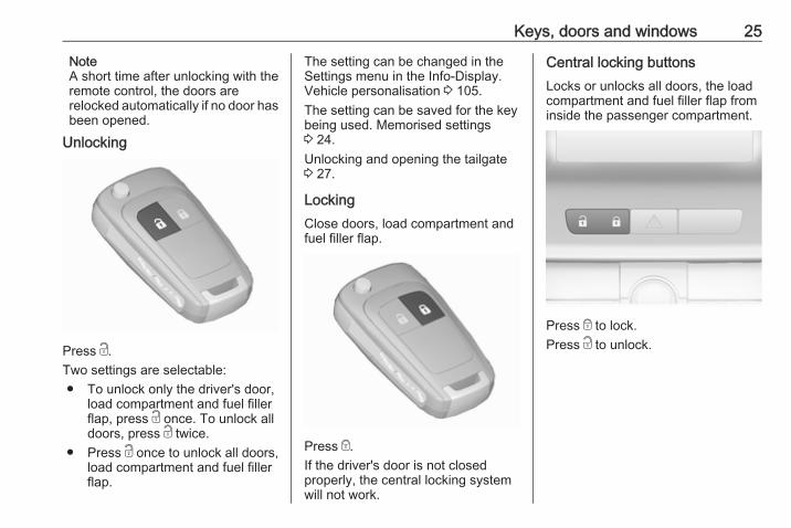
Unlocking
Press c.Two settings are selectable:● To unlock only the driver's door,
load compartment and fuel fillerflap, press c once. To unlock alldoors, press c twice.
● Press c once to unlock all doors,load compartment and fuel fillerflap.
The setting can be changed in theSettings menu in the Info-Display.Vehicle personalisation 3 105.The setting can be saved for the keybeing used. Memorised settings3 24.Unlocking and opening the tailgate3 27.
LockingClose doors, load compartment andfuel filler flap.
Press e.If the driver's door is not closedproperly, the central locking systemwill not work.
Central locking buttonsLocks or unlocks all doors, the loadcompartment and fuel filler flap frominside the passenger compartment.
Press e to lock.Press c to unlock.
26 Keys, doors and windows
Fault in radio remote controlsystem
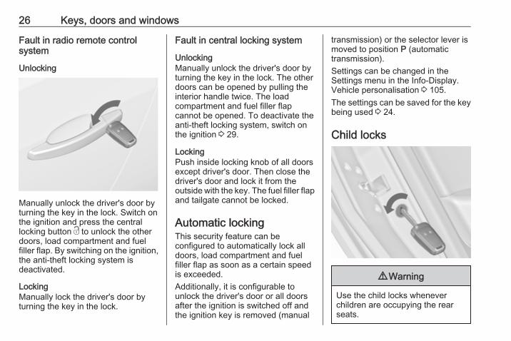
Unlocking
Manually unlock the driver's door byturning the key in the lock. Switch onthe ignition and press the centrallocking button c to unlock the otherdoors, load compartment and fuelfiller flap. By switching on the ignition,the anti-theft locking system isdeactivated.
LockingManually lock the driver's door byturning the key in the lock.
Fault in central locking system
UnlockingManually unlock the driver's door byturning the key in the lock. The otherdoors can be opened by pulling theinterior handle twice. The loadcompartment and fuel filler flapcannot be opened. To deactivate theanti-theft locking system, switch onthe ignition 3 29.
LockingPush inside locking knob of all doorsexcept driver's door. Then close thedriver's door and lock it from theoutside with the key. The fuel filler flapand tailgate cannot be locked.
Automatic lockingThis security feature can beconfigured to automatically lock alldoors, load compartment and fuelfiller flap as soon as a certain speedis exceeded.Additionally, it is configurable tounlock the driver's door or all doorsafter the ignition is switched off andthe ignition key is removed (manual
transmission) or the selector lever ismoved to position P (automatictransmission).Settings can be changed in theSettings menu in the Info-Display.Vehicle personalisation 3 105.The settings can be saved for the keybeing used 3 24.
Child locks
9 Warning
Use the child locks wheneverchildren are occupying the rearseats.
Keys, doors and windows 27
Using a key or suitable screwdriver,turn the child lock in the rear door tothe horizontal position. The doorcannot be opened from the inside.To deactivate, turn the child lock tothe vertical position.
DoorsLoad compartmentTailgate
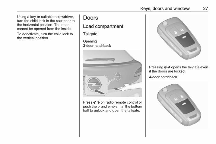
Opening3-door hatchback
Press x on radio remote control orpush the brand emblem at the bottomhalf to unlock and open the tailgate.
Pressing x opens the tailgate evenif the doors are locked.4-door notchback
28 Keys, doors and windows
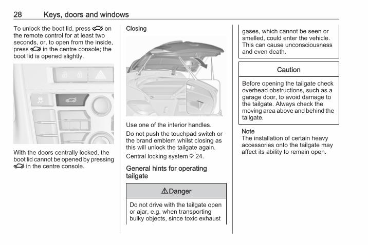
To unlock the boot lid, press x onthe remote control for at least twoseconds, or, to open from the inside,press x in the centre console; theboot lid is opened slightly.
With the doors centrally locked, theboot lid cannot be opened by pressingx in the centre console.
Closing
Use one of the interior handles.Do not push the touchpad switch orthe brand emblem whilst closing asthis will unlock the tailgate again.Central locking system 3 24.
General hints for operatingtailgate
9 Danger
Do not drive with the tailgate openor ajar, e.g. when transportingbulky objects, since toxic exhaust
gases, which cannot be seen orsmelled, could enter the vehicle.This can cause unconsciousnessand even death.
Caution
Before opening the tailgate checkoverhead obstructions, such as agarage door, to avoid damage tothe tailgate. Always check themoving area above and behind thetailgate.
NoteThe installation of certain heavyaccessories onto the tailgate mayaffect its ability to remain open.

Keys, doors and windows 29
Vehicle securityAnti-theft locking system
9 Warning
Do not use the system if there arepeople in the vehicle! The doorscannot be unlocked from theinside.
The system deadlocks all the doors.All doors must be closed otherwisethe system cannot be activated.If the ignition was on, the driver's doormust be opened and closed once sothat the vehicle can be secured.Unlocking the vehicle disables themechanical anti-theft locking system.This is not possible with the centrallocking button.
Activating
Press e on the radio remote controltwice within 15 seconds.
Anti-theft alarm systemThe anti-theft alarm system iscombined with the anti-theft lockingsystem.It monitors:● doors, tailgate, bonnet● passenger compartment
including adjoining loadcompartment
● vehicle inclination, e.g. if it israised
● ignition
Activation● Self-activated 30 seconds after
locking the vehicle by pressing eonce.
● Directly by pressing e twicebriefly within five seconds.
NoteChanges to the vehicle interior suchas the use of seat covers, and openwindows or sunroof, could impair thefunction of passenger compartmentmonitoring.
30 Keys, doors and windows
Activation without monitoring ofpassenger compartment andvehicle inclination
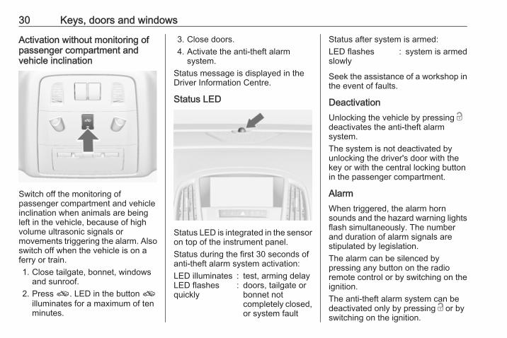
Switch off the monitoring ofpassenger compartment and vehicleinclination when animals are beingleft in the vehicle, because of highvolume ultrasonic signals ormovements triggering the alarm. Alsoswitch off when the vehicle is on aferry or train.1. Close tailgate, bonnet, windows
and sunroof.2. Press o. LED in the button o
illuminates for a maximum of tenminutes.
3. Close doors.4. Activate the anti-theft alarm
system.Status message is displayed in theDriver Information Centre.
Status LED
Status LED is integrated in the sensoron top of the instrument panel.Status during the first 30 seconds ofanti-theft alarm system activation:LED illuminates : test, arming delayLED flashesquickly
: doors, tailgate orbonnet notcompletely closed,or system fault
Status after system is armed:LED flashesslowly
: system is armed
Seek the assistance of a workshop inthe event of faults.
DeactivationUnlocking the vehicle by pressing cdeactivates the anti-theft alarmsystem.The system is not deactivated byunlocking the driver's door with thekey or with the central locking buttonin the passenger compartment.
AlarmWhen triggered, the alarm hornsounds and the hazard warning lightsflash simultaneously. The numberand duration of alarm signals arestipulated by legislation.The alarm can be silenced bypressing any button on the radioremote control or by switching on theignition.The anti-theft alarm system can bedeactivated only by pressing c or byswitching on the ignition.
Keys, doors and windows 31
A triggered alarm, which has not beeninterrupted by the driver, will beindicated by the hazard warninglights. They will flash quickly threetimes the next time the vehicle isunlocked with the radio remotecontrol. Additionally, a warningmessage or a warning code isdisplayed in the Driver InformationCentre after switching on the ignition.Vehicle messages 3 99.If the vehicle's battery is to bedisconnected (e.g. for maintenancework), the alarm siren must bedeactivated as follows: Switch theignition on then off, then disconnectthe vehicle's battery within15 seconds.
ImmobiliserThe system is part of the ignitionswitch and checks whether thevehicle is allowed to be started withthe key being used.The immobiliser is activatedautomatically after the key has beenremoved from the ignition switch.
If the control indicator d flashes whenthe ignition is on, there is a fault in thesystem; the engine cannot be started.Switch off the ignition and repeat thestart attempt.If the control indicator continuesflashing, attempt to start the engineusing the spare key and seek theassistance of a workshop.NoteThe immobiliser does not lock thedoors. You should always lock thevehicle after leaving it and switch onthe anti-theft alarm system 3 24,3 29.
Control indicator d 3 92.
Exterior mirrorsConvex shapeThe convex exterior mirror containsan aspherical area and reduces blindspots. The shape of the mirror makesobjects appear smaller, which willaffect the ability to estimatedistances.
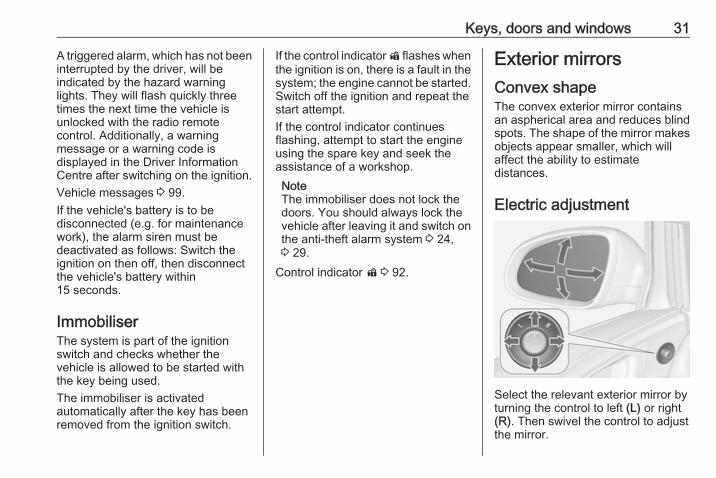
Electric adjustment
Select the relevant exterior mirror byturning the control to left (L) or right(R). Then swivel the control to adjustthe mirror.
32 Keys, doors and windows
In position 0 no mirror is selected.
Folding mirrors
For pedestrian safety, the exteriormirrors will swing out of their normalmounting position if they are struckwith sufficient force. Reposition themirror by applying slight pressure tothe mirror housing.
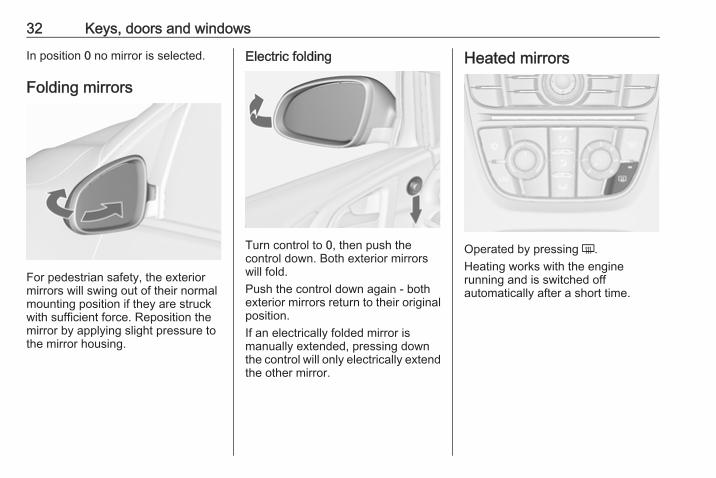
Electric folding
Turn control to 0, then push thecontrol down. Both exterior mirrorswill fold.Push the control down again - bothexterior mirrors return to their originalposition.If an electrically folded mirror ismanually extended, pressing downthe control will only electrically extendthe other mirror.
Heated mirrors
Operated by pressing Ü.Heating works with the enginerunning and is switched offautomatically after a short time.
Keys, doors and windows 33
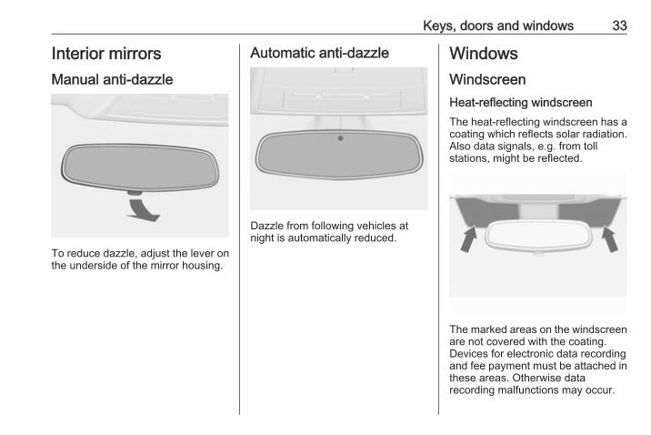
Interior mirrorsManual anti-dazzle
To reduce dazzle, adjust the lever onthe underside of the mirror housing.
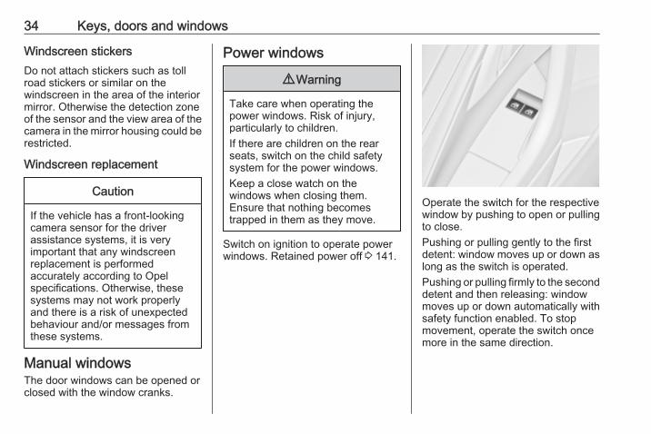
Automatic anti-dazzle
Dazzle from following vehicles atnight is automatically reduced.
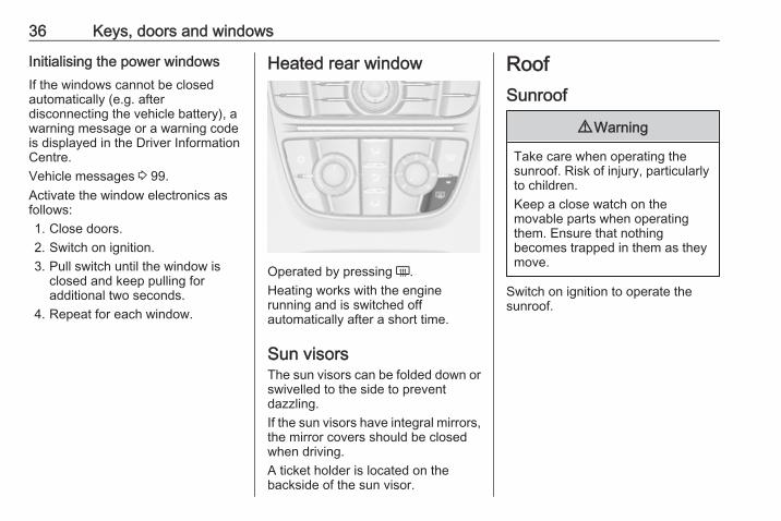
WindowsWindscreenHeat-reflecting windscreenThe heat-reflecting windscreen has acoating which reflects solar radiation.Also data signals, e.g. from tollstations, might be reflected.
The marked areas on the windscreenare not covered with the coating.Devices for electronic data recordingand fee payment must be attached inthese areas. Otherwise datarecording malfunctions may occur.
34 Keys, doors and windows
Windscreen stickersDo not attach stickers such as tollroad stickers or similar on thewindscreen in the area of the interiormirror. Otherwise the detection zoneof the sensor and the view area of thecamera in the mirror housing could berestricted.
Windscreen replacement
Caution
If the vehicle has a front-lookingcamera sensor for the driverassistance systems, it is veryimportant that any windscreenreplacement is performedaccurately according to Opelspecifications. Otherwise, thesesystems may not work properlyand there is a risk of unexpectedbehaviour and/or messages fromthese systems.
Manual windowsThe door windows can be opened orclosed with the window cranks.
Power windows
9 Warning
Take care when operating thepower windows. Risk of injury,particularly to children.If there are children on the rearseats, switch on the child safetysystem for the power windows.Keep a close watch on thewindows when closing them.Ensure that nothing becomestrapped in them as they move.
Switch on ignition to operate powerwindows. Retained power off 3 141.
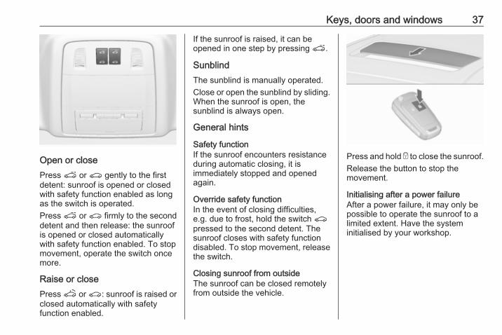
Operate the switch for the respectivewindow by pushing to open or pullingto close.Pushing or pulling gently to the firstdetent: window moves up or down aslong as the switch is operated.Pushing or pulling firmly to the seconddetent and then releasing: windowmoves up or down automatically withsafety function enabled. To stopmovement, operate the switch oncemore in the same direction.

Keys, doors and windows 35
Safety functionIf the window glass encountersresistance above the middle of thewindow during automatic closing, it isimmediately stopped and openedagain.
Override safety functionIn the event of closing difficulties dueto frost or the like, switch on theignition, then pull the switch to the firstdetent and hold. The window movesup without safety function enabled.To stop movement, release theswitch.
Child safety system for rearwindows
Press z to deactivate rear doorpower windows; the LED illuminates.To activate, press z again.
Operating windows from outsideThe windows can be operatedremotely from outside the vehicle.
Press and hold c to open windows.Press and hold e to close windows.Release button to stop windowmovement.If the windows are fully opened orclosed, the hazard warning lights willflash twice.
OverloadIf the windows are repeatedlyoperated within short intervals, thewindow operation is disabled forsome time.
36 Keys, doors and windows
Initialising the power windowsIf the windows cannot be closedautomatically (e.g. afterdisconnecting the vehicle battery), awarning message or a warning codeis displayed in the Driver InformationCentre.Vehicle messages 3 99.Activate the window electronics asfollows:1. Close doors.2. Switch on ignition.3. Pull switch until the window is
closed and keep pulling foradditional two seconds.
4. Repeat for each window.
Heated rear window
Operated by pressing Ü.Heating works with the enginerunning and is switched offautomatically after a short time.
Sun visorsThe sun visors can be folded down orswivelled to the side to preventdazzling.If the sun visors have integral mirrors,the mirror covers should be closedwhen driving.A ticket holder is located on thebackside of the sun visor.
RoofSunroof
9 Warning
Take care when operating thesunroof. Risk of injury, particularlyto children.Keep a close watch on themovable parts when operatingthem. Ensure that nothingbecomes trapped in them as theymove.
Switch on ignition to operate thesunroof.
Keys, doors and windows 37
Open or closePress p or r gently to the firstdetent: sunroof is opened or closedwith safety function enabled as longas the switch is operated.Press p or r firmly to the seconddetent and then release: the sunroofis opened or closed automaticallywith safety function enabled. To stopmovement, operate the switch oncemore.
Raise or closePress q or r: sunroof is raised orclosed automatically with safetyfunction enabled.
If the sunroof is raised, it can beopened in one step by pressing p.
SunblindThe sunblind is manually operated.Close or open the sunblind by sliding.When the sunroof is open, thesunblind is always open.
General hints
Safety functionIf the sunroof encounters resistanceduring automatic closing, it isimmediately stopped and openedagain.
Override safety functionIn the event of closing difficulties,e.g. due to frost, hold the switch rpressed to the second detent. Thesunroof closes with safety functiondisabled. To stop movement, releasethe switch.
Closing sunroof from outsideThe sunroof can be closed remotelyfrom outside the vehicle.
Press and hold e to close the sunroof.Release the button to stop themovement.
Initialising after a power failureAfter a power failure, it may only bepossible to operate the sunroof to alimited extent. Have the systeminitialised by your workshop.
38 Keys, doors and windows
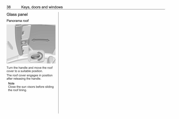
Glass panelPanorama roof
Turn the handle and move the roofcover to a suitable position.The roof cover engages in positionafter releasing the handle.NoteClose the sun visors before slidingthe roof lining.
Seats, restraints 39
Seats, restraints
Head restraints ............................ 39Active head restraints ................ 40
Front seats ................................... 41Seat position .............................. 41Manual seat adjustment ............ 42Seat folding ............................... 44Power seat adjustment .............. 45Armrest ...................................... 47Heating ...................................... 47
Rear seats ................................... 48Armrest ...................................... 48
Seat belts ..................................... 48Three-point seat belt ................. 49
Airbag system .............................. 51Front airbag system ................... 51Side airbag system .................... 52Curtain airbag system ............... 53Airbag deactivation .................... 53
Child restraints ............................. 55Child restraint systems .............. 55Child restraint installationlocations ................................... 57
ISOFIX child restraint systems . . 60Top-tether fastening eyes .......... 60
Head restraints
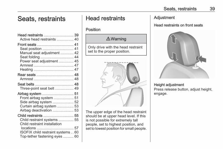
Position
9 Warning
Only drive with the head restraintset to the proper position.
The upper edge of the head restraintshould be at upper head level. If thisis not possible for extremely tallpeople, set to highest position, andset to lowest position for small people.
Adjustment
Head restraints on front seats
Height adjustmentPress release button, adjust height,engage.
40 Seats, restraints
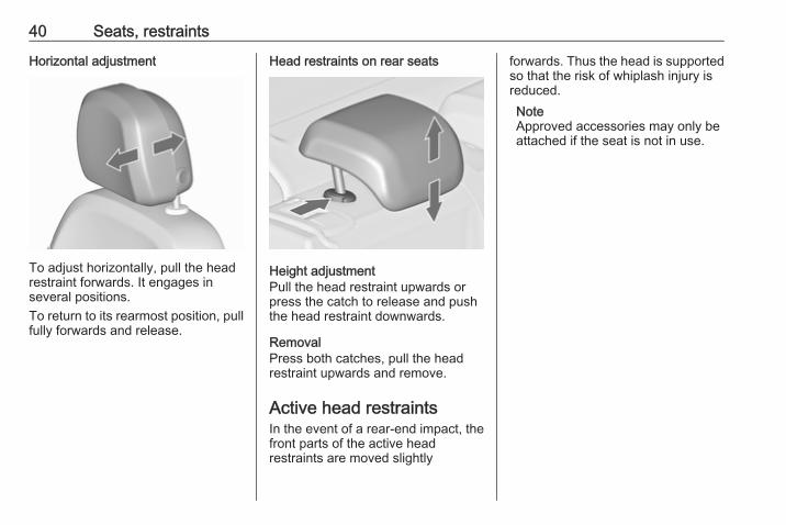
Horizontal adjustment
To adjust horizontally, pull the headrestraint forwards. It engages inseveral positions.To return to its rearmost position, pullfully forwards and release.
Head restraints on rear seats
Height adjustmentPull the head restraint upwards orpress the catch to release and pushthe head restraint downwards.
RemovalPress both catches, pull the headrestraint upwards and remove.
Active head restraintsIn the event of a rear-end impact, thefront parts of the active headrestraints are moved slightly
forwards. Thus the head is supportedso that the risk of whiplash injury isreduced.NoteApproved accessories may only beattached if the seat is not in use.
Seats, restraints 41
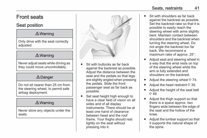
Front seatsSeat position
9 Warning
Only drive with the seat correctlyadjusted.
9 Warning
Never adjust seats while driving asthey could move uncontrollably.
9 Danger
Do not sit nearer than 25 cm fromthe steering wheel, to permit safeairbag deployment.
9 Warning
Never store any objects under theseats.
● Sit with buttocks as far backagainst the backrest as possible.Adjust the distance between theseat and the pedals so that legsare slightly angled when pressingthe pedals. Slide the frontpassenger seat as far back aspossible.
● Set seat height high enough tohave a clear field of vision on allsides and of all displayinstruments. There should be atleast one hand of clearancebetween head and the roofframe. Your thighs should restlightly on the seat withoutpressing into it.
● Sit with shoulders as far backagainst the backrest as possible.Set the backrest rake so that it ispossible to easily reach thesteering wheel with arms slightlybent. Maintain contact betweenshoulders and the backrest whenturning the steering wheel. Donot angle the backrest too farback. We recommend amaximum rake of approx. 25°.
● Adjust seat and steering wheel ina way that the wrist rests on topof the steering wheel while thearm is fully extended andshoulders on the backrest.
● Adjust the steering wheel 3 74.● Adjust the head restraint 3 39.● Adjust the height of the seat belt
3 49.● Adjust the thigh support so that
there is a space approx. twofingers wide between the edge ofthe seat and the hollow of theknee.
● Adjust the lumbar support so thatit supports the natural shape ofthe spine.
42 Seats, restraints
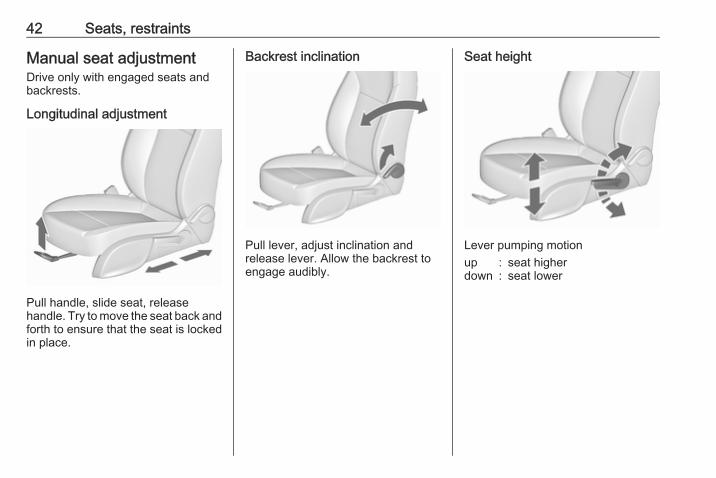
Manual seat adjustmentDrive only with engaged seats andbackrests.
Longitudinal adjustment
Pull handle, slide seat, releasehandle. Try to move the seat back andforth to ensure that the seat is lockedin place.
Backrest inclination
Pull lever, adjust inclination andrelease lever. Allow the backrest toengage audibly.
Seat height
Lever pumping motionup : seat higherdown : seat lower
Seats, restraints 43
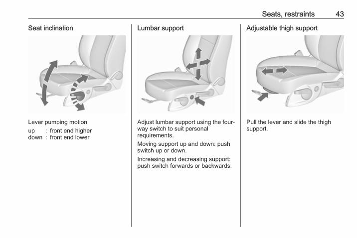
Seat inclination
Lever pumping motionup : front end higherdown : front end lower
Lumbar support
Adjust lumbar support using the four-way switch to suit personalrequirements.Moving support up and down: pushswitch up or down.Increasing and decreasing support:push switch forwards or backwards.
Adjustable thigh support
Pull the lever and slide the thighsupport.
44 Seats, restraints
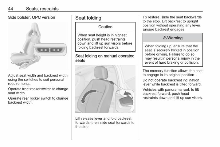
Side bolster, OPC version
Adjust seat width and backrest widthusing the switches to suit personalrequirements.Operate front rocker switch to changeseat width.Operate rear rocker switch to changebackrest width.
Seat folding
Caution
When seat height is in highestposition, push head restraintsdown and lift up sun visors beforefolding backrest forwards.
Seat folding on manual operatedseats
Lift release lever and fold backrestforwards, then slide seat forwards tothe stop.
To restore, slide the seat backwardsto the stop. Lift backrest to uprightposition without operating any lever.Ensure backrest engages.
9 Warning
When folding up, ensure that theseat is securely locked in positionbefore driving. Failure to do somay result in personal injury in theevent of hard braking or collision.
The memory function allows the seatto engage in its original position.Do not operate backrest inclinationlever while backrest is tilted forward.Vehicles with panorama roof: to tiltbackrest forward, push headrestraints down and lift up sun visors.
Seats, restraints 45
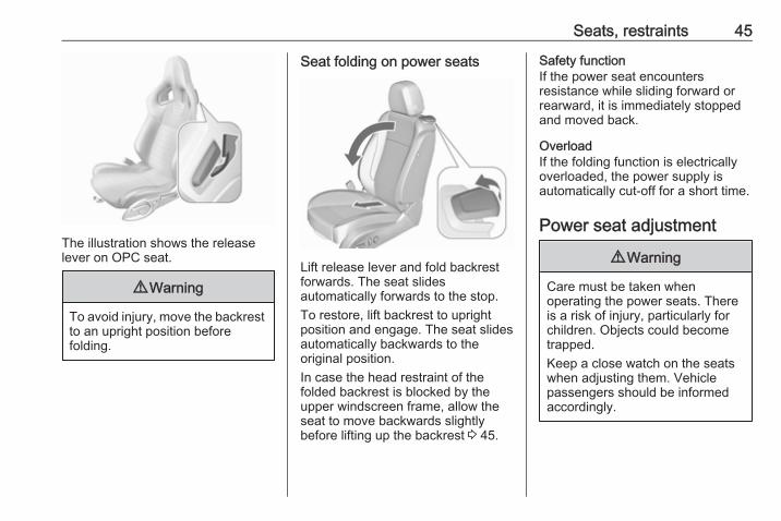
The illustration shows the releaselever on OPC seat.
9 Warning
To avoid injury, move the backrestto an upright position beforefolding.
Seat folding on power seats
Lift release lever and fold backrestforwards. The seat slidesautomatically forwards to the stop.To restore, lift backrest to uprightposition and engage. The seat slidesautomatically backwards to theoriginal position.In case the head restraint of thefolded backrest is blocked by theupper windscreen frame, allow theseat to move backwards slightlybefore lifting up the backrest 3 45.
Safety functionIf the power seat encountersresistance while sliding forward orrearward, it is immediately stoppedand moved back.
OverloadIf the folding function is electricallyoverloaded, the power supply isautomatically cut-off for a short time.
Power seat adjustment
9 Warning
Care must be taken whenoperating the power seats. Thereis a risk of injury, particularly forchildren. Objects could becometrapped.Keep a close watch on the seatswhen adjusting them. Vehiclepassengers should be informedaccordingly.
46 Seats, restraints
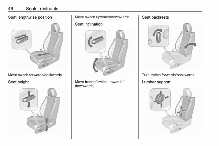
Seat lengthwise position
Move switch forwards/backwards.
Seat height
Move switch upwards/downwards.
Seat inclination
Move front of switch upwards/downwards.
Seat backrests
Turn switch forwards/backwards.
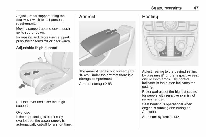
Lumbar support
Seats, restraints 47
Adjust lumbar support using thefour-way switch to suit personalrequirements.Moving support up and down: pushswitch up or down.Increasing and decreasing support:push switch forwards or backwards.
Adjustable thigh support
Pull the lever and slide the thighsupport.
OverloadIf the seat setting is electricallyoverloaded, the power supply isautomatically cut-off for a short time.
Armrest
The armrest can be slid forwards by10 cm. Under the armrest there is astorage compartment.Armrest storage 3 63.
Heating
Adjust heating to the desired settingby pressing ß for the respective seatone or more times. The controlindicator in the button indicates thesetting.Prolonged use of the highest settingfor people with sensitive skin is notrecommended.Seat heating is operational whenengine is running and during anAutostop.Stop-start system 3 142.
48 Seats, restraints
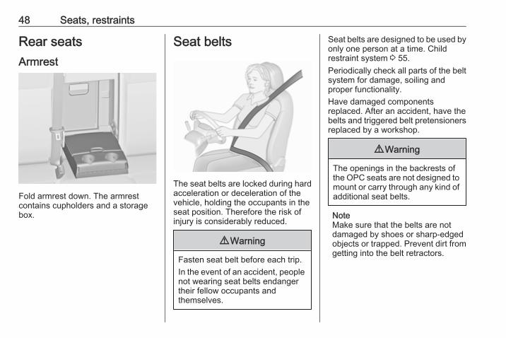
Rear seatsArmrest
Fold armrest down. The armrestcontains cupholders and a storagebox.
Seat belts
The seat belts are locked during hardacceleration or deceleration of thevehicle, holding the occupants in theseat position. Therefore the risk ofinjury is considerably reduced.
9 Warning
Fasten seat belt before each trip.In the event of an accident, peoplenot wearing seat belts endangertheir fellow occupants andthemselves.
Seat belts are designed to be used byonly one person at a time. Childrestraint system 3 55.Periodically check all parts of the beltsystem for damage, soiling andproper functionality.Have damaged componentsreplaced. After an accident, have thebelts and triggered belt pretensionersreplaced by a workshop.
9 Warning
The openings in the backrests ofthe OPC seats are not designed tomount or carry through any kind ofadditional seat belts.
NoteMake sure that the belts are notdamaged by shoes or sharp-edgedobjects or trapped. Prevent dirt fromgetting into the belt retractors.
Seats, restraints 49
Seat belt reminderFront seats are equipped with a seatbelt reminder, indicated for driver seatby control indicator X in thetachometer 3 87 and for passengerseat by the control indicators in thecentre console 3 84.
Belt force limitersOn the front seats, stress on the bodyis reduced by the gradual release ofthe belt during a collision.
Belt pretensionersIn the event of a head-on or rear-endcollision of a certain severity, the frontseat belts are tightened.
9 Warning
Incorrect handling (e.g. removal orfitting of belts) can trigger the beltpretensioners.
Deployment of the belt pretensionersis indicated by continuous illuminationof control indicator v 3 87.
Triggered belt pretensioners must bereplaced by a workshop. Beltpretensioners can only be triggeredonce.NoteDo not affix or install accessories orother objects that may interfere withthe operation of the beltpretensioners. Do not make anymodifications to belt pretensionercomponents as this will invalidatethe vehicle type approval.
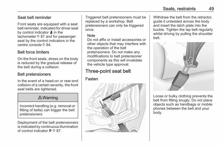
Three-point seat beltFasten
Withdraw the belt from the retractor,guide it untwisted across the bodyand insert the latch plate into thebuckle. Tighten the lap belt regularlywhilst driving by pulling the shoulderbelt.
Loose or bulky clothing prevents thebelt from fitting snugly. Do not placeobjects such as handbags or mobilephones between the belt and yourbody.
50 Seats, restraints
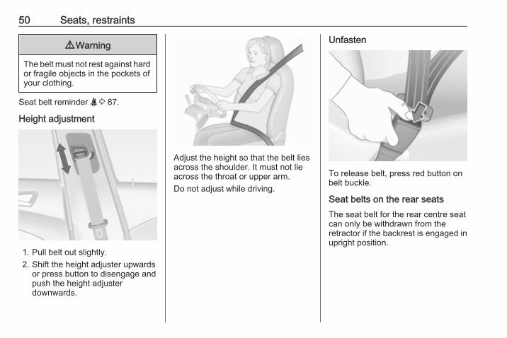
9 Warning
The belt must not rest against hardor fragile objects in the pockets ofyour clothing.
Seat belt reminder X 3 87.
Height adjustment
1. Pull belt out slightly.2. Shift the height adjuster upwards
or press button to disengage andpush the height adjusterdownwards.
Adjust the height so that the belt liesacross the shoulder. It must not lieacross the throat or upper arm.Do not adjust while driving.
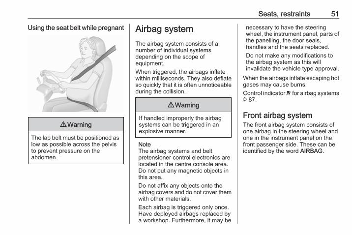
Unfasten
To release belt, press red button onbelt buckle.
Seat belts on the rear seatsThe seat belt for the rear centre seatcan only be withdrawn from theretractor if the backrest is engaged inupright position.
Seats, restraints 51
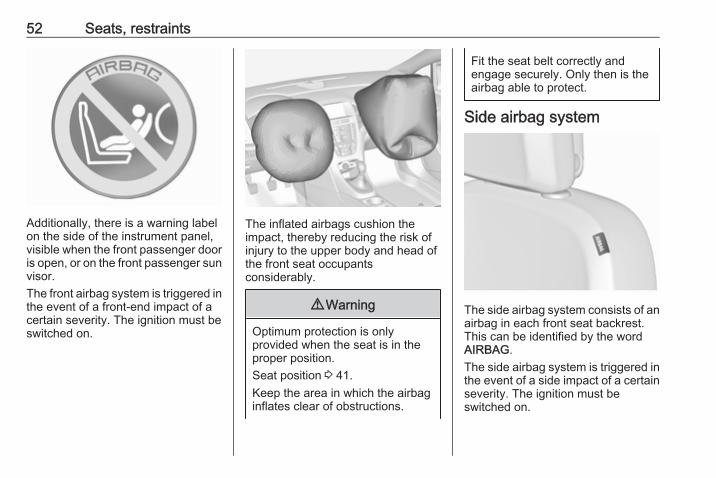
Using the seat belt while pregnant
9 Warning
The lap belt must be positioned aslow as possible across the pelvisto prevent pressure on theabdomen.
Airbag systemThe airbag system consists of anumber of individual systemsdepending on the scope ofequipment.When triggered, the airbags inflatewithin milliseconds. They also deflateso quickly that it is often unnoticeableduring the collision.
9 Warning
If handled improperly the airbagsystems can be triggered in anexplosive manner.
NoteThe airbag systems and beltpretensioner control electronics arelocated in the centre console area.Do not put any magnetic objects inthis area.Do not affix any objects onto theairbag covers and do not cover themwith other materials.Each airbag is triggered only once.Have deployed airbags replaced bya workshop. Furthermore, it may be
necessary to have the steeringwheel, the instrument panel, parts ofthe panelling, the door seals,handles and the seats replaced.Do not make any modifications tothe airbag system as this willinvalidate the vehicle type approval.
When the airbags inflate escaping hotgases may cause burns.Control indicator v for airbag systems3 87.
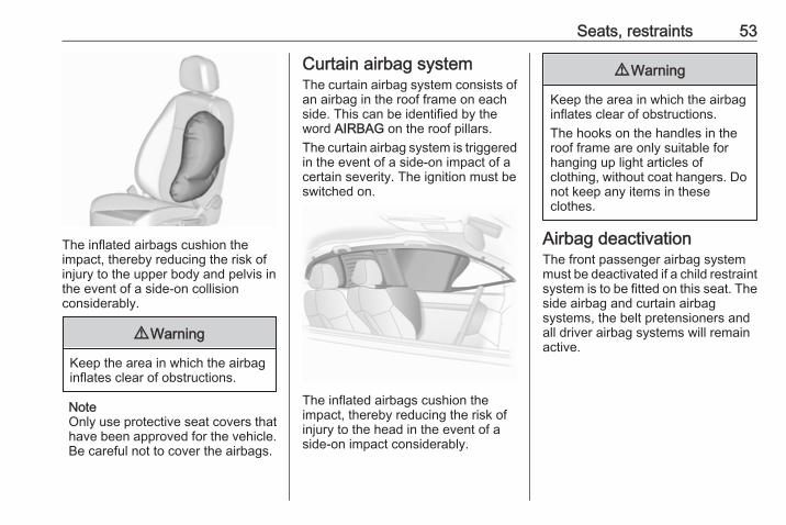
Front airbag systemThe front airbag system consists ofone airbag in the steering wheel andone in the instrument panel on thefront passenger side. These can beidentified by the word AIRBAG.
52 Seats, restraints
Additionally, there is a warning labelon the side of the instrument panel,visible when the front passenger dooris open, or on the front passenger sunvisor.The front airbag system is triggered inthe event of a front-end impact of acertain severity. The ignition must beswitched on.
The inflated airbags cushion theimpact, thereby reducing the risk ofinjury to the upper body and head ofthe front seat occupantsconsiderably.
9 Warning
Optimum protection is onlyprovided when the seat is in theproper position.Seat position 3 41.Keep the area in which the airbaginflates clear of obstructions.
Fit the seat belt correctly andengage securely. Only then is theairbag able to protect.
Side airbag system
The side airbag system consists of anairbag in each front seat backrest.This can be identified by the wordAIRBAG.The side airbag system is triggered inthe event of a side impact of a certainseverity. The ignition must beswitched on.
Seats, restraints 53
The inflated airbags cushion theimpact, thereby reducing the risk ofinjury to the upper body and pelvis inthe event of a side-on collisionconsiderably.
9 Warning
Keep the area in which the airbaginflates clear of obstructions.
NoteOnly use protective seat covers thathave been approved for the vehicle.Be careful not to cover the airbags.
Curtain airbag systemThe curtain airbag system consists ofan airbag in the roof frame on eachside. This can be identified by theword AIRBAG on the roof pillars.The curtain airbag system is triggeredin the event of a side-on impact of acertain severity. The ignition must beswitched on.
The inflated airbags cushion theimpact, thereby reducing the risk ofinjury to the head in the event of aside-on impact considerably.
9 Warning
Keep the area in which the airbaginflates clear of obstructions.The hooks on the handles in theroof frame are only suitable forhanging up light articles ofclothing, without coat hangers. Donot keep any items in theseclothes.
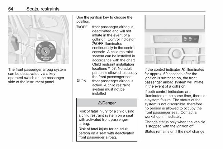
Airbag deactivationThe front passenger airbag systemmust be deactivated if a child restraintsystem is to be fitted on this seat. Theside airbag and curtain airbagsystems, the belt pretensioners andall driver airbag systems will remainactive.
54 Seats, restraints
The front passenger airbag systemcan be deactivated via a key-operated switch on the passengerside of the instrument panel.
Use the ignition key to choose theposition:*OFF : front passenger airbag is
deactivated and will notinflate in the event of acollision. Control indicator*OFF illuminatescontinuously in the centreconsole. A child restraintsystem can be installed inaccordance with the chartChild restraint installationlocations 3 57. No adultperson is allowed to occupythe front passenger seat
VON : front passenger airbag isactive. A child restraintsystem must not beinstalled
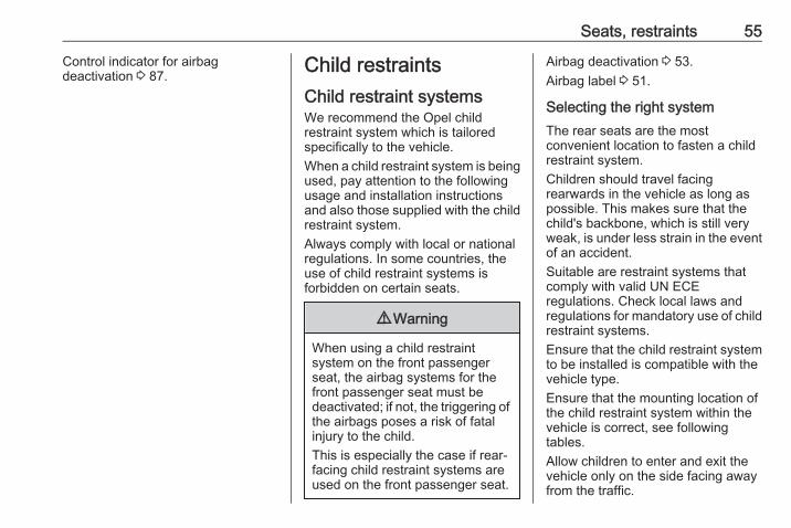
9 Danger
Risk of fatal injury for a child usinga child restraint system on a seatwith activated front passengerairbag.Risk of fatal injury for an adultperson on a seat with deactivatedfront passenger airbag.
If the control indicator V illuminatesfor approx. 60 seconds after theignition is switched on, the frontpassenger airbag system will inflatein the event of a collision.If both control indicators areilluminated at the same time, there isa system failure. The status of thesystem is not discernible, thereforeno person is allowed to occupy thefront passenger seat. Contact aworkshop immediately.Change status only when the vehicleis stopped with the ignition off.Status remains until the next change.
Seats, restraints 55
Control indicator for airbagdeactivation 3 87. Child restraints
Child restraint systemsWe recommend the Opel childrestraint system which is tailoredspecifically to the vehicle.When a child restraint system is beingused, pay attention to the followingusage and installation instructionsand also those supplied with the childrestraint system.Always comply with local or nationalregulations. In some countries, theuse of child restraint systems isforbidden on certain seats.
9 Warning
When using a child restraintsystem on the front passengerseat, the airbag systems for thefront passenger seat must bedeactivated; if not, the triggering ofthe airbags poses a risk of fatalinjury to the child.This is especially the case if rear-facing child restraint systems areused on the front passenger seat.
Airbag deactivation 3 53.Airbag label 3 51.
Selecting the right systemThe rear seats are the mostconvenient location to fasten a childrestraint system.Children should travel facingrearwards in the vehicle as long aspossible. This makes sure that thechild's backbone, which is still veryweak, is under less strain in the eventof an accident.Suitable are restraint systems thatcomply with valid UN ECEregulations. Check local laws andregulations for mandatory use of childrestraint systems.Ensure that the child restraint systemto be installed is compatible with thevehicle type.Ensure that the mounting location ofthe child restraint system within thevehicle is correct, see followingtables.Allow children to enter and exit thevehicle only on the side facing awayfrom the traffic.
56 Seats, restraints
When the child restraint system is notin use, secure the seat with a seat beltor remove it from the vehicle.NoteDo not affix anything on the childrestraint systems and do not coverthem with any other materials.A child restraint system which hasbeen subjected to stress in anaccident must be replaced.
Seats, restraints 57
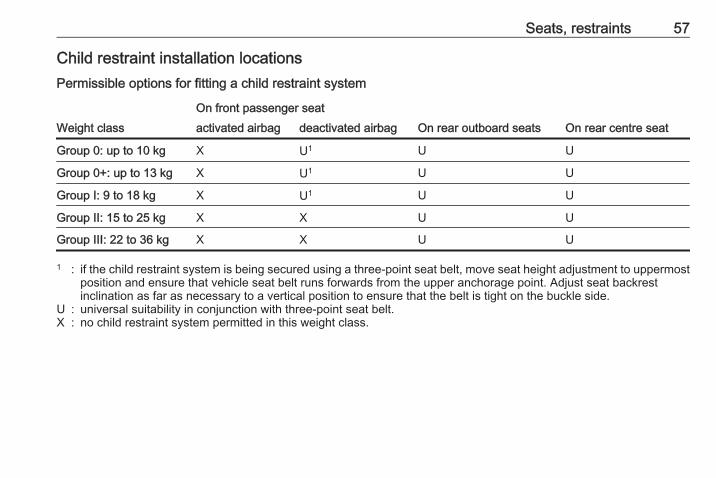
Child restraint installation locationsPermissible options for fitting a child restraint system
Weight classOn front passenger seat
On rear outboard seats On rear centre seatactivated airbag deactivated airbag
Group 0: up to 10 kg X U1 U U
Group 0+: up to 13 kg X U1 U U
Group I: 9 to 18 kg X U1 U U
Group II: 15 to 25 kg X X U U
Group III: 22 to 36 kg X X U U
1 : if the child restraint system is being secured using a three-point seat belt, move seat height adjustment to uppermostposition and ensure that vehicle seat belt runs forwards from the upper anchorage point. Adjust seat backrestinclination as far as necessary to a vertical position to ensure that the belt is tight on the buckle side.
U : universal suitability in conjunction with three-point seat belt.X : no child restraint system permitted in this weight class.
58 Seats, restraints
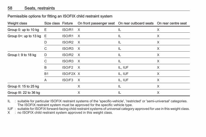
Permissible options for fitting an ISOFIX child restraint system
Weight class Size class Fixture On front passenger seat On rear outboard seats On rear centre seat
Group 0: up to 10 kg E ISO/R1 X IL X
Group 0+: up to 13 kg E ISO/R1 X IL X
D ISO/R2 X IL X
C ISO/R3 X IL X
Group I: 9 to 18 kg D ISO/R2 X IL X
C ISO/R3 X IL X
B ISO/F2 X IL, IUF X
B1 ISO/F2X X IL, IUF X
A ISO/F3 X IL, IUF X
Group II: 15 to 25 kg X IL X
Group III: 22 to 36 kg X IL X
IL : suitable for particular ISOFIX restraint systems of the 'specific-vehicle', 'restricted' or 'semi-universal' categories.The ISOFIX restraint system must be approved for the specific vehicle type.
IUF : suitable for ISOFIX forward-facing child restraint systems of universal category approved for use in this weight class.X : no ISOFIX child restraint system approved in this weight class.
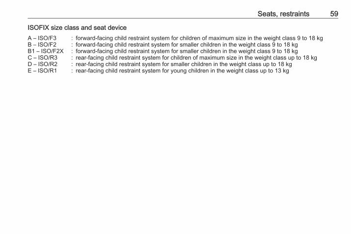
Seats, restraints 59
ISOFIX size class and seat deviceA – ISO/F3 : forward-facing child restraint system for children of maximum size in the weight class 9 to 18 kgB – ISO/F2 : forward-facing child restraint system for smaller children in the weight class 9 to 18 kgB1 – ISO/F2X : forward-facing child restraint system for smaller children in the weight class 9 to 18 kgC – ISO/R3 : rear-facing child restraint system for children of maximum size in the weight class up to 18 kgD – ISO/R2 : rear-facing child restraint system for smaller children in the weight class up to 18 kgE – ISO/R1 : rear-facing child restraint system for young children in the weight class up to 13 kg
60 Seats, restraints
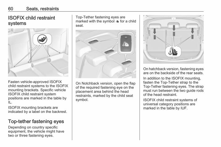
ISOFIX child restraintsystems
Fasten vehicle-approved ISOFIXchild restraint systems to the ISOFIXmounting brackets. Specific vehicleISOFIX child restraint systempositions are marked in the table byIL.ISOFIX mounting brackets areindicated by a label on the backrest.
Top-tether fastening eyesDepending on country specificequipment, the vehicle might havetwo or three fastening eyes.
Top-Tether fastening eyes aremarked with the symbol : for a childseat.
On Notchback version, open the flapof the required fastening eye on theplacement area behind the headrestraints, marked by the child seatsymbol.
On hatchback version, fastening eyesare on the backside of the rear seats.In addition to the ISOFIX mounting,fasten the Top-Tether strap to theTop-Tether fastening eyes. The strapmust run between the two guide rodsof the head restraint.ISOFIX child restraint systems ofuniversal category positions aremarked in the table by IUF.
Storage 61
Storage
Storage compartments ................ 61Glovebox ................................... 61Cupholders ................................ 61Front storage ............................. 62Underseat storage ..................... 63Armrest storage ......................... 63Centre console storage ............. 64
Load compartment ....................... 65Rear storage .............................. 67Load compartment cover ........... 67Rear floor storage cover ............ 68Lashing eyes ............................. 69Warning triangle ........................ 70First aid kit ................................. 70
Roof rack system ......................... 71Roof rack ................................... 71
Loading information ..................... 71
Storage compartments
9 Warning
Do not store heavy or sharpobjects in the storagecompartments. Otherwise, thestorage compartment lid couldopen and vehicle occupants couldbe injured by objects being thrownaround in the event of hardbraking, a sudden change indirection or an accident.
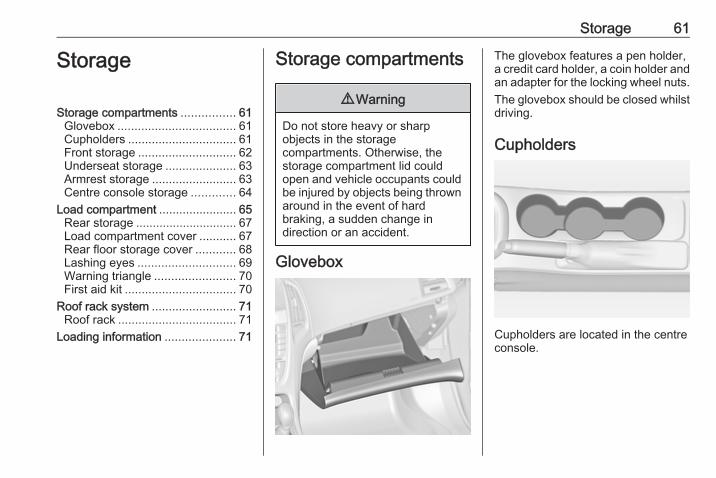
Glovebox
The glovebox features a pen holder,a credit card holder, a coin holder andan adapter for the locking wheel nuts.The glovebox should be closed whilstdriving.
Cupholders
Cupholders are located in the centreconsole.

62 Storage
Depending on the version,cupholders are located under a coverin the centre console. Slide coverbackwards. Bottles can be stowedafter folding up the intermediate shelf3 64.
Additional cupholders are located inthe rear armrest. Fold down thearmrest.
Front storage
A storage compartment is locatednext to the steering wheel.

Storage 63
Underseat storage
Press button in the recess and pull outdrawer. Maximum load: 3 kg. Toclose, push in and engage.
Armrest storageStorage under the front armrest
Press button to fold up the armrest.The armrest must be in rearmostposition.
Storage in the rear armrest
Fold down armrest and open cover.Close cover before folding thearmrest up.
64 Storage
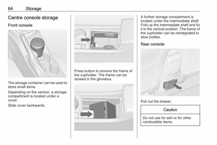
Centre console storageFront console
The storage container can be used tostore small items.Depending on the version, a storagecompartment is located under acover.Slide cover backwards.
Press button to remove the frame ofthe cupholder. The frame can bestowed in the glovebox.
A further storage compartment islocated under the intermediate shelf.Fold up the intermediate shelf and fixit in the vertical position. The frame ofthe cupholder can be reintegrated tostow bottles.
Rear console
Pull out the drawer.
Caution
Do not use for ash or for othercombustible items.

Storage 65
Load compartmentThe rear seat backrest is divided intotwo parts. Both parts can be foldeddown.
Load compartment extension● Only 3-door hatchback: remove
the load compartment cover ifnecessary.
● Press and hold the catch to pushthe head restraints down 3 39.
● Fold up the rear armrest.
● Guide the seat belts through sidesupports to protect them againstdamage. When folding thebackrests, pull the seat beltsalong with them.
● Pull the release lever on one orboth sides and fold down thebackrests onto the seat cushion.
● Take the seat belt out of the seatbackrest guide and put it behindthe retainer as shown in theillustration.
To fold up, raise the backrests andguide them into an upright positionuntil they engage audibly.
Ensure that the seat belts of theoutboard seats are placed in thecorresponding belt guides.
The backrests are properly engagedwhen the red marks on both sidesnear the release lever are no longervisible.
9 Warning
When folding up, ensure thatbackrests are securely locked inposition before driving. Failure todo so may result in personal injury
66 Storage
or damage to the load or vehicle inthe event of hard braking or acollision.
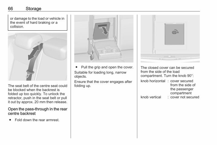
The seat belt of the centre seat couldbe blocked when the backrest isfolded up too quickly. To unlock theretractor, push in the seat belt or pullit out by approx. 20 mm then release.
Open the pass-through in the rearcentre backrest● Fold down the rear armrest.
● Pull the grip and open the cover.Suitable for loading long, narrowobjects.Ensure that the cover engages afterfolding up.
The closed cover can be securedfrom the side of the loadcompartment. Turn the knob 90°:knob horizontal : cover secured
from the side ofthe passengercompartment
knob vertical : cover not secured

Storage 67
Rear storage3-door hatchback
Press both buttons and fold downcover.Maximum load: 0.5 kg.
Load compartment coverDo not place any objects on the cover.
3-door hatchback
Removing
Unhook retaining straps from tailgate.
Lift cover at the rear and push itupwards at the front.Remove the cover.If the height adjustable cover ismounted in the middle or upperposition, the load compartment covercan be stowed below it.Height adjustable cover 3 68.
FittingEngage cover in side guides and folddownwards. Attach retaining straps totailgate.
68 Storage
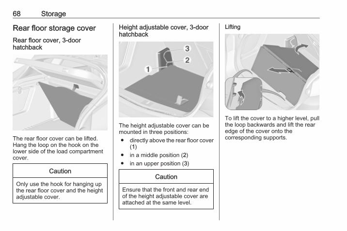
Rear floor storage coverRear floor cover, 3-doorhatchback
The rear floor cover can be lifted.Hang the loop on the hook on thelower side of the load compartmentcover.
Caution
Only use the hook for hanging upthe rear floor cover and the heightadjustable cover.
Height adjustable cover, 3-doorhatchback
The height adjustable cover can bemounted in three positions:● directly above the rear floor cover
(1)● in a middle position (2)● in an upper position (3)
Caution
Ensure that the front and rear endof the height adjustable cover areattached at the same level.
Lifting
To lift the cover to a higher level, pullthe loop backwards and lift the rearedge of the cover onto thecorresponding supports.
Storage 69
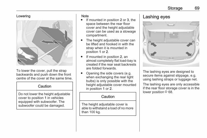
Lowering
To lower the cover, pull the strapbackwards and push down the frontcentre of the cover at the same time.
Caution
Do not lower the height adjustablecover to position 1 in vehiclesequipped with subwoofer. Thesubwoofer could be damaged.
Note● If mounted in position 2 or 3, the
space between the rear floorcover and the height adjustablecover can be used as a stowagecompartment.
● The height adjustable cover canbe lifted and hooked in with thestrap when it is mounted inposition 1 or 2.
● If mounted in position 2, analmost completely flat load-bay iscreated if the rear seat backrestsare folded forwards.
● Opening the side covers (e.g.when exchanging the rear lightbulbs) is only possible with theheight adjustable cover mountedin position 1 or 2.
Caution
The height adjustable cover isable to withstand a load of no morethan 100 kg.
Lashing eyes
The lashing eyes are designed tosecure items against slippage, e.g.using lashing straps or luggage net.The lashing eyes are only accessibleif the rear floor storage cover is in thelower position 3 68.
70 Storage
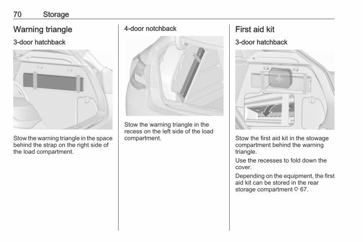
Warning triangle3-door hatchback
Stow the warning triangle in the spacebehind the strap on the right side ofthe load compartment.
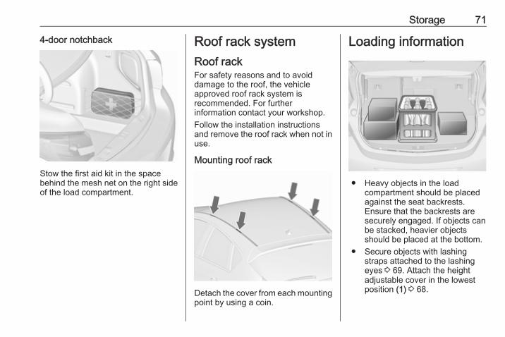
4-door notchback
Stow the warning triangle in therecess on the left side of the loadcompartment.
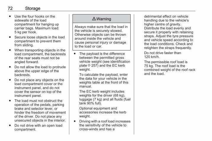
First aid kit3-door hatchback
Stow the first aid kit in the stowagecompartment behind the warningtriangle.Use the recesses to fold down thecover.Depending on the equipment, the firstaid kit can be stored in the rearstorage compartment 3 67.
Storage 71
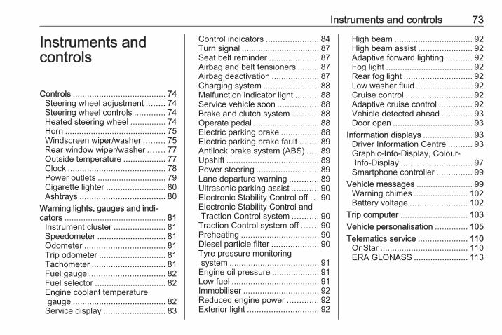
4-door notchback
Stow the first aid kit in the spacebehind the mesh net on the right sideof the load compartment.
Roof rack systemRoof rackFor safety reasons and to avoiddamage to the roof, the vehicleapproved roof rack system isrecommended. For furtherinformation contact your workshop.Follow the installation instructionsand remove the roof rack when not inuse.
Mounting roof rack
Detach the cover from each mountingpoint by using a coin.
Loading information
● Heavy objects in the loadcompartment should be placedagainst the seat backrests.Ensure that the backrests aresecurely engaged. If objects canbe stacked, heavier objectsshould be placed at the bottom.
● Secure objects with lashingstraps attached to the lashingeyes 3 69. Attach the heightadjustable cover in the lowestposition (1) 3 68.
72 Storage
● Use the four hooks on thesidewalls of the loadcompartment for hanging upcarrier bags. Maximum load:5 kg per hook.
● Secure loose objects in the loadcompartment to prevent themfrom sliding.
● When transporting objects in theload compartment, the backrestsof the rear seats must not beangled forward.
● Do not allow the load to protrudeabove the upper edge of thebackrests.
● Do not place any objects on theload compartment cover or theinstrument panel, and do notcover the sensor on top of theinstrument panel.
● The load must not obstruct theoperation of the pedals, parkingbrake and selector lever, orhinder the freedom of movementof the driver. Do not place anyunsecured objects in the interior.
● Do not drive with an open loadcompartment.
9 Warning
Always make sure that the load inthe vehicle is securely stowed.Otherwise objects can be thrownaround inside the vehicle andcause personal injury or damageto the load or car.
● The payload is the differencebetween the permitted grossvehicle weight (see identificationplate 3 257) and the EC kerbweight.To calculate the payload, enterthe data for your vehicle in theweights table at the front of thismanual.The EC kerb weight includesweights for the driver (68 kg),luggage (7 kg) and all fluids (fueltank 90% full).Optional equipment andaccessories increase the kerbweight.
● Driving with a roof load increasesthe sensitivity of the vehicle tocross-winds and has a
detrimental effect on vehiclehandling due to the vehicle'shigher centre of gravity.Distribute the load evenly andsecure it properly with retainingstraps. Adjust the tyre pressureand vehicle speed according tothe load conditions. Check andretighten the straps frequently.Do not drive faster than120 km/h.The permissible roof load is75 kg. The roof load is thecombined weight of the roof rackand the load.
Instruments and controls 73
Instruments andcontrols
Controls ....................................... 74Steering wheel adjustment ........ 74Steering wheel controls ............. 74Heated steering wheel ............... 74Horn ........................................... 75Windscreen wiper/washer ......... 75Rear window wiper/washer ....... 77Outside temperature .................. 77Clock ......................................... 78Power outlets ............................. 79Cigarette lighter ......................... 80Ashtrays .................................... 80
Warning lights, gauges and indi‐cators ........................................... 81
Instrument cluster ...................... 81Speedometer ............................. 81Odometer .................................. 81Trip odometer ............................ 81Tachometer ............................... 81Fuel gauge ................................ 82Fuel selector .............................. 82Engine coolant temperaturegauge ....................................... 82
Service display .......................... 83
Control indicators ...................... 84Turn signal ................................. 87Seat belt reminder ..................... 87Airbag and belt tensioners ......... 87Airbag deactivation .................... 87Charging system ....................... 88Malfunction indicator light .......... 88Service vehicle soon ................. 88Brake and clutch system ........... 88Operate pedal ............................ 88Electric parking brake ................ 88Electric parking brake fault ........ 89Antilock brake system (ABS) ..... 89Upshift ....................................... 89Power steering .......................... 89Lane departure warning ............ 89Ultrasonic parking assist ........... 90Electronic Stability Control off . . . 90Electronic Stability Control andTraction Control system ........... 90
Traction Control system off ....... 90Preheating ................................. 90Diesel particle filter .................... 90Tyre pressure monitoringsystem ...................................... 91
Engine oil pressure .................... 91Low fuel ..................................... 91Immobiliser ................................ 92Reduced engine power ............. 92Exterior light .............................. 92
High beam ................................. 92High beam assist ....................... 92Adaptive forward lighting ........... 92Fog light ..................................... 92Rear fog light ............................. 92Low washer fluid ........................ 92Cruise control ............................ 92Adaptive cruise control .............. 92Vehicle detected ahead ............. 93Door open .................................. 93
Information displays ..................... 93Driver Information Centre .......... 93Graphic-Info-Display, Colour-Info-Display .............................. 97
Smartphone controller ............... 99Vehicle messages ........................ 99
Warning chimes ....................... 102Battery voltage ........................ 102
Trip computer ............................. 103Vehicle personalisation .............. 105Telematics service ..................... 110
OnStar ..................................... 110ERA GLONASS ....................... 113
74 Instruments and controls
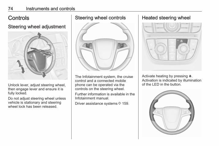
ControlsSteering wheel adjustment
Unlock lever, adjust steering wheel,then engage lever and ensure it isfully locked.Do not adjust steering wheel unlessvehicle is stationary and steeringwheel lock has been released.
Steering wheel controls
The Infotainment system, the cruisecontrol and a connected mobilephone can be operated via thecontrols on the steering wheel.Further information is available in theInfotainment manual.Driver assistance systems 3 159.
Heated steering wheel
Activate heating by pressing *.Activation is indicated by illuminationof the LED in the button.

Instruments and controls 75
The recommended grip areas of thesteering wheel are heated quickerand to a higher temperature than theother areas.Heating is operational when theengine is running and during anAutostop.Stop-start system 3 142.
Horn
Press j.
Windscreen wiper/washerWindscreen wiper
HI : fastLO : slowINT : interval wiping or automatic
wiping with rain sensorOFF : off
For a single wipe when thewindscreen wiper is off, press thelever down to position 1x.Do not use if the windscreen is frozen.Switch off in car washes.
Adjustable wiper interval
Wiper lever in position INT.Turn the adjuster wheel to adjust thedesired wipe interval:short interval : turn adjuster
wheel upwardslong interval : turn adjuster
wheel downwards
76 Instruments and controls
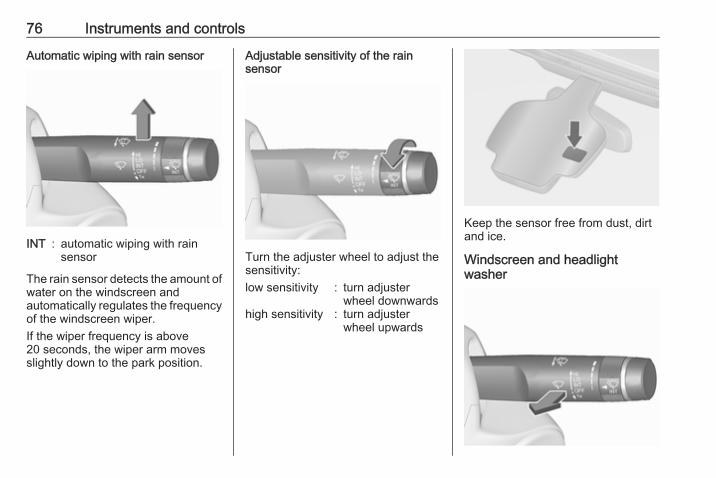
Automatic wiping with rain sensor
INT : automatic wiping with rainsensor
The rain sensor detects the amount ofwater on the windscreen andautomatically regulates the frequencyof the windscreen wiper.If the wiper frequency is above20 seconds, the wiper arm movesslightly down to the park position.
Adjustable sensitivity of the rainsensor
Turn the adjuster wheel to adjust thesensitivity:low sensitivity : turn adjuster
wheel downwardshigh sensitivity : turn adjuster
wheel upwards
Keep the sensor free from dust, dirtand ice.
Windscreen and headlightwasher
Instruments and controls 77
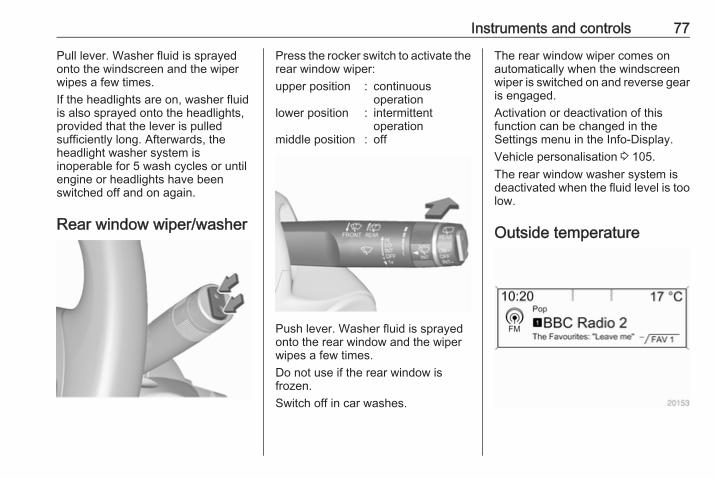
Pull lever. Washer fluid is sprayedonto the windscreen and the wiperwipes a few times.If the headlights are on, washer fluidis also sprayed onto the headlights,provided that the lever is pulledsufficiently long. Afterwards, theheadlight washer system isinoperable for 5 wash cycles or untilengine or headlights have beenswitched off and on again.
Rear window wiper/washer
Press the rocker switch to activate therear window wiper:upper position : continuous
operationlower position : intermittent
operationmiddle position : off
Push lever. Washer fluid is sprayedonto the rear window and the wiperwipes a few times.Do not use if the rear window isfrozen.Switch off in car washes.
The rear window wiper comes onautomatically when the windscreenwiper is switched on and reverse gearis engaged.Activation or deactivation of thisfunction can be changed in theSettings menu in the Info-Display.Vehicle personalisation 3 105.The rear window washer system isdeactivated when the fluid level is toolow.
Outside temperature
78 Instruments and controls
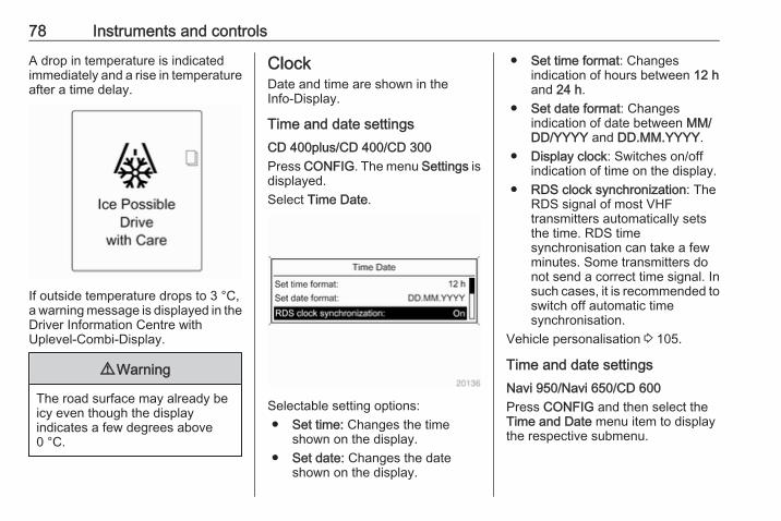
A drop in temperature is indicatedimmediately and a rise in temperatureafter a time delay.
If outside temperature drops to 3 °C,a warning message is displayed in theDriver Information Centre withUplevel-Combi-Display.
9 Warning
The road surface may already beicy even though the displayindicates a few degrees above0 °C.
ClockDate and time are shown in theInfo-Display.
Time and date settingsCD 400plus/CD 400/CD 300Press CONFIG. The menu Settings isdisplayed.Select Time Date.
Selectable setting options:● Set time: Changes the time
shown on the display.● Set date: Changes the date
shown on the display.
● Set time format: Changesindication of hours between 12 hand 24 h.
● Set date format: Changesindication of date between MM/DD/YYYY and DD.MM.YYYY.
● Display clock: Switches on/offindication of time on the display.
● RDS clock synchronization: TheRDS signal of most VHFtransmitters automatically setsthe time. RDS timesynchronisation can take a fewminutes. Some transmitters donot send a correct time signal. Insuch cases, it is recommended toswitch off automatic timesynchronisation.
Vehicle personalisation 3 105.
Time and date settingsNavi 950/Navi 650/CD 600Press CONFIG and then select theTime and Date menu item to displaythe respective submenu.
Instruments and controls 79
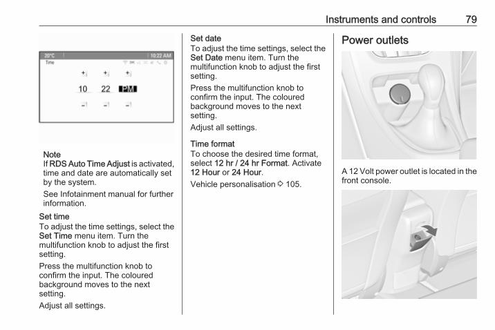
NoteIf RDS Auto Time Adjust is activated,time and date are automatically setby the system.See Infotainment manual for furtherinformation.
Set timeTo adjust the time settings, select theSet Time menu item. Turn themultifunction knob to adjust the firstsetting.Press the multifunction knob toconfirm the input. The colouredbackground moves to the nextsetting.Adjust all settings.
Set dateTo adjust the time settings, select theSet Date menu item. Turn themultifunction knob to adjust the firstsetting.Press the multifunction knob toconfirm the input. The colouredbackground moves to the nextsetting.Adjust all settings.
Time formatTo choose the desired time format,select 12 hr / 24 hr Format. Activate12 Hour or 24 Hour.Vehicle personalisation 3 105.
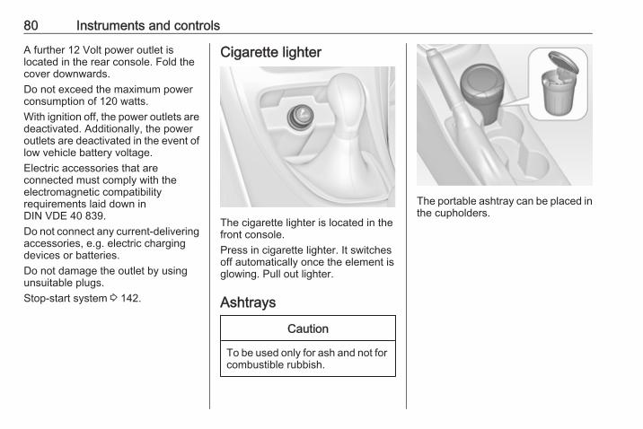
Power outlets
A 12 Volt power outlet is located in thefront console.
80 Instruments and controls
A further 12 Volt power outlet islocated in the rear console. Fold thecover downwards.Do not exceed the maximum powerconsumption of 120 watts.With ignition off, the power outlets aredeactivated. Additionally, the poweroutlets are deactivated in the event oflow vehicle battery voltage.Electric accessories that areconnected must comply with theelectromagnetic compatibilityrequirements laid down inDIN VDE 40 839.Do not connect any current-deliveringaccessories, e.g. electric chargingdevices or batteries.Do not damage the outlet by usingunsuitable plugs.Stop-start system 3 142.
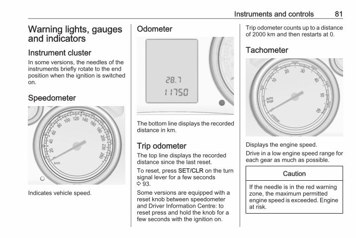
Cigarette lighter
The cigarette lighter is located in thefront console.Press in cigarette lighter. It switchesoff automatically once the element isglowing. Pull out lighter.
Ashtrays
Caution
To be used only for ash and not forcombustible rubbish.
The portable ashtray can be placed inthe cupholders.
Instruments and controls 81
Warning lights, gaugesand indicatorsInstrument clusterIn some versions, the needles of theinstruments briefly rotate to the endposition when the ignition is switchedon.
Speedometer
Indicates vehicle speed.
Odometer
The bottom line displays the recordeddistance in km.
Trip odometerThe top line displays the recordeddistance since the last reset.To reset, press SET/CLR on the turnsignal lever for a few seconds3 93.Some versions are equipped with areset knob between speedometerand Driver Information Centre: toreset press and hold the knob for afew seconds with the ignition on.
Trip odometer counts up to a distanceof 2000 km and then restarts at 0.
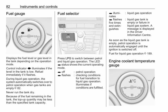
Tachometer
Displays the engine speed.Drive in a low engine speed range foreach gear as much as possible.
Caution
If the needle is in the red warningzone, the maximum permittedengine speed is exceeded. Engineat risk.
82 Instruments and controls
Fuel gauge
Displays the fuel level or gas level inthe tank depending on the operationmode.Control indicator i illuminates if thelevel in the tank is low. Refuelimmediately if it flashes.During liquid gas operation, thesystem automatically switches over topetrol operation when gas tanks areempty 3 82.Never run the tank dry.Because of the fuel remaining in thetank, the top-up quantity may be lessthan the specified tank capacity.
Fuel selector
Press LPG to switch between petroland liquid gas operation. The LED1 status shows the current operatingmode.1 off : petrol operation1 flashes : checking conditions
for fuel transition toliquid gas operation.Illuminates ifconditions are fulfilled.
1 illumi‐nates
: liquid gas operation
1 flashesfive timesand extin‐guishes
: liquid gas tank isempty or failure inliquid gas system. Amessage is displayedin the DriverInformation Centre.
As soon as the liquid gas tank isempty, petrol operation isautomatically engaged until theignition is switched off.Fuel for liquid gas operation 3 189.
Engine coolant temperaturegauge

Instruments and controls 83
Displays the coolant temperature.left area : engine operating
temperature not yetreached
centralarea
: normal operatingtemperature
right area : temperature too high
Caution
If engine coolant temperature istoo high, stop vehicle, switch offengine. Danger to engine. Checkcoolant level.
Service displayThe engine oil life system lets youknow when to change the engine oiland filter. Based on drivingconditions, the interval at which anengine oil and filter change will beindicated can vary considerably.To display the remaining engine oillife duration use turn signal leverbuttons:
Press MENU to select the VehicleInformation Menu X.Turn the adjuster wheel to selectRemaining Oil Life.
The remaining engine oil life durationis displayed in percent in the DriverInformation Centre.
ResetPress SET/CLR on turn signal leverfor several seconds to reset. Theremaining engine oil life durationpage must be active. Switch onignition, but not the engine.The system must be reset every timethe engine oil is changed, to ensureproper functionality. Seek theassistance of a workshop.
Next serviceWhen the system has calculated thatengine oil life has diminished, awarning message appears in theDriver Information Centre. Haveengine oil and filter changed by aworkshop within one week or500 km (whichever occurs first).Driver Information Centre 3 93.Service information 3 254.

84 Instruments and controls
Control indicatorsThe control indicators described arenot present in all vehicles. Thedescription applies to all instrumentversions. Depending on theequipment, the position of the controlindicators may vary. When theignition is switched on, most controlindicators will illuminate briefly as afunctionality test.The control indicator colours mean:red : danger, important reminderyellow : warning, information, faultgreen : confirmation of activationblue : confirmation of activationwhite : confirmation of activation
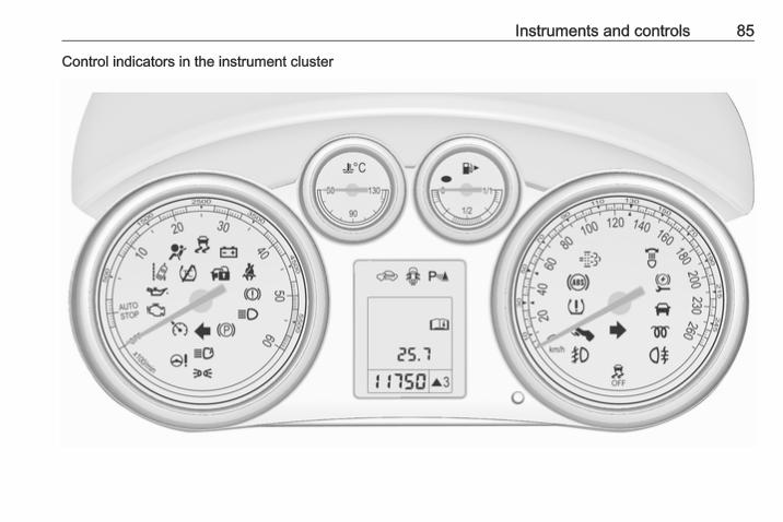
Instruments and controls 85
Control indicators in the instrument cluster

86 Instruments and controls
Control indicators in the centreconsole
Overview
O Turn signal 3 87
X Seat belt reminder 3 87
v Airbag and belt tensioners3 87
V Airbag deactivation 3 87
p Charging system 3 88
Z Malfunction indicator light3 88
g Service vehicle soon 3 88
R Brake and clutch system3 88
- Operate pedal 3 88
m Electric parking brake 3 88
j Electric parking brake fault3 89
u Antilock brake system (ABS)3 89
[ Upshift 3 89
c Power steering 3 89
) Lane departure warning 3 89
r Ultrasonic parking assist3 90
n Electronic Stability Control off3 90
b Electronic Stability Control andTraction Control system 3 90
k Traction Control system off3 90
! Preheating 3 90
% Diesel particle filter 3 90
w Tyre pressure monitoringsystem 3 91
I Engine oil pressure 3 91
i Low fuel 3 91
d Immobiliser 3 92
# Reduced engine power 3 92
8 Exterior light 3 92
C High beam 3 92
l High beam assist 3 92
f Adaptive forward lighting3 92
> Fog light 3 92
r Rear fog light 3 92
G Low washer fluid 3 92
m Cruise control 3 92 / Adaptivecruise control 3 92
A Vehicle detected ahead 3 93
h Door open 3 93
Instruments and controls 87
Turn signalO illuminates or flashes green.
Illuminates brieflyThe parking lights are switched on.
FlashesA turn signal or the hazard warningflashers are activated.Rapid flashing: failure of a turn signallight or associated fuse, failure of turnsignal light on trailer.Bulb replacement 3 209, Fuses3 223.Turn signals 3 123.
Seat belt reminderSeat belt reminder on front seatsX for driver's seat illuminates orflashes red.k for front passenger seat illuminatesor flashes red, when the seat isoccupied.
IlluminatesAfter the ignition has been switchedon until the seat belt has beenfastened.
FlashesAfter having started the engine for amaximum of 100 seconds until theseat belt has been fastened.
Airbag and belt tensionersv illuminates red.When the ignition is switched on, thecontrol indicator illuminates forapprox. four seconds. If it does notilluminate, does not go out after fourseconds or illuminates whilst driving,there is a fault in the airbag system.Seek the assistance of a workshop.The airbags and belt pretensionersmay fail to trigger in the event of anaccident.Deployment of the belt pretensionersor airbags is indicated by continuousillumination of v.
9 Warning
Have the cause of the faultremedied immediately by aworkshop.
Belt pretensioners, airbag system3 48, 3 51.
Airbag deactivationV illuminates yellow.Illuminates for approx. 60 secondsafter the ignition is switched on. Thefront passenger airbag is activated.* illuminates yellow.The front passenger airbag isdeactivated 3 53.
9 Danger
Risk of fatal injury for a child usinga child restraint system togetherwith activated front passengerairbag.Risk of fatal injury for an adultperson with deactivated frontpassenger airbag.
88 Instruments and controls
Charging systemp illuminates red.Illuminates when the ignition isswitched on and extinguishes shortlyafter the engine starts.
Illuminates when the engine isrunningStop, switch off engine. Vehiclebattery is not charging. Enginecooling may be interrupted. Thebrake servo unit may cease to beeffective. Seek the assistance of aworkshop.
Malfunction indicator lightZ illuminates or flashes yellow.Illuminates when the ignition isswitched on and extinguishes shortlyafter the engine starts.
Illuminates when the engine isrunningFault in the emission control system.The permitted emission limits may beexceeded. Seek the assistance of aworkshop immediately.
Flashes when the engine isrunningFault that could lead to catalyticconverter damage. Ease up on theaccelerator until the flashing stops.Seek the assistance of a workshopimmediately.
Service vehicle soong illuminates yellow.Additionally, a warning message or awarning code is displayed.The vehicle needs a service.Seek the assistance of a workshop.Vehicle messages 3 99.
Brake and clutch systemR illuminates red.The brake and clutch fluid level is toolow 3 206.
9 Warning
Stop. Do not continue yourjourney. Consult a workshop.
Illuminates after the ignition isswitched on if the manual parkingbrake is applied 3 152.
Operate pedal- illuminates or flashes yellow.
IlluminatesBrake pedal needs to be depressedto release the electric parking brake3 152.Clutch pedal needs to be depressedto start the engine in Autostop mode.Stop-start system 3 142.
FlashesClutch pedal needs to be depressedfor a main start of the engine 3 19,3 141.On some versions the operate pedalmessage is indicated in the DriverInformation Centre 3 99.
Electric parking brakem illuminates or flashes red.
Instruments and controls 89
IlluminatesElectric parking brake is applied3 152.
FlashesElectric parking brake is not fullyapplied or released. Switch onignition, depress brake pedal andattempt to reset the system by firstreleasing and then applying theelectric parking brake. If m remainsflashing, do not drive and seek theassistance of a workshop.
Electric parking brake faultj illuminates or flashes yellow.
IlluminatesElectric parking brake is operatingwith reduced performance 3 152.
FlashesElectric parking brake is in servicemode. Stop vehicle, apply andrelease the electric parking brake toreset.
9 Warning
Have the cause of the faultremedied immediately by aworkshop.
Antilock brake system(ABS)u illuminates yellow.Illuminates for a few seconds after theignition is switched on. The system isready for operation when the controlindicator extinguishes.If the control indicator does not go outafter a few seconds, or if it illuminateswhile driving, there is a fault in theABS. The brake system remainsoperational but without ABSregulation.Antilock brake system 3 151.
Upshift[ illuminates green as a controlindicator, or is shown as a symbol Rwith the number of a higher gear in the
Driver Information Centre, whenupshifting is recommended for fuelsaving reasons.On some versions, gearshiftindication is popped-up as full page inthe Driver Information Centre.EcoFlex drive assistant 3 103.
Power steeringc illuminates yellow.
Illuminates with power steeringreducedPower steering is reduced due tooverheating of the system. Controlindicator extinguishes when thesystem has cooled down.Stop-start system 3 142.
Illuminates with power steeringdisabledFailure in the power steering system.Consult a workshop.
Lane departure warning) illuminates green or flashes yellow.
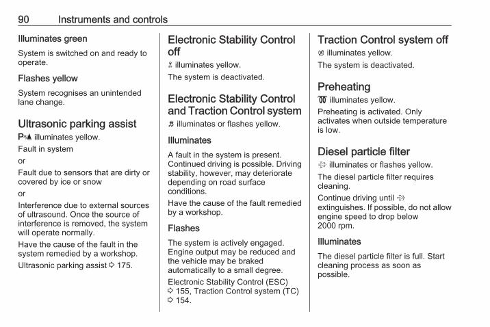
90 Instruments and controls
Illuminates greenSystem is switched on and ready tooperate.
Flashes yellowSystem recognises an unintendedlane change.
Ultrasonic parking assistr illuminates yellow.Fault in systemorFault due to sensors that are dirty orcovered by ice or snoworInterference due to external sourcesof ultrasound. Once the source ofinterference is removed, the systemwill operate normally.Have the cause of the fault in thesystem remedied by a workshop.Ultrasonic parking assist 3 175.
Electronic Stability Controloffn illuminates yellow.The system is deactivated.
Electronic Stability Controland Traction Control systemb illuminates or flashes yellow.
IlluminatesA fault in the system is present.Continued driving is possible. Drivingstability, however, may deterioratedepending on road surfaceconditions.Have the cause of the fault remediedby a workshop.
FlashesThe system is actively engaged.Engine output may be reduced andthe vehicle may be brakedautomatically to a small degree.Electronic Stability Control (ESC)3 155, Traction Control system (TC)3 154.
Traction Control system offk illuminates yellow.The system is deactivated.
Preheating! illuminates yellow.Preheating is activated. Onlyactivates when outside temperatureis low.
Diesel particle filter% illuminates or flashes yellow.The diesel particle filter requirescleaning.Continue driving until %extinguishes. If possible, do not allowengine speed to drop below2000 rpm.
IlluminatesThe diesel particle filter is full. Startcleaning process as soon aspossible.
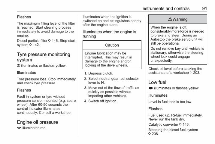
Instruments and controls 91
FlashesThe maximum filling level of the filteris reached. Start cleaning processimmediately to avoid damage to theengine.Diesel particle filter 3 145, Stop-startsystem 3 142.
Tyre pressure monitoringsystemw illuminates or flashes yellow.
IlluminatesTyre pressure loss. Stop immediatelyand check tyre pressure.
FlashesFault in system or tyre withoutpressure sensor mounted (e.g. sparewheel). After 60-90 seconds thecontrol indicator illuminatescontinuously. Consult a workshop.
Engine oil pressureI illuminates red.
Illuminates when the ignition isswitched on and extinguishes shortlyafter the engine starts.
Illuminates when the engine isrunning
Caution
Engine lubrication may beinterrupted. This may result indamage to the engine and/orlocking of the drive wheels.
1. Depress clutch.2. Select neutral gear, set selector
lever to N.3. Move out of the flow of traffic as
quickly as possible withoutimpeding other vehicles.
4. Switch off ignition.
9 Warning
When the engine is off,considerably more force is neededto brake and steer. During anAutostop the brake servo unit willstill be operational.Do not remove key until vehicle isstationary, otherwise the steeringwheel lock could engageunexpectedly.
Check oil level before seeking theassistance of a workshop 3 203.
Low fueli illuminates or flashes yellow.
IlluminatesLevel in fuel tank is too low.
FlashesFuel used up. Refuel immediately.Never run the tank dry.Catalytic converter 3 146.Bleeding the diesel fuel system3 208.
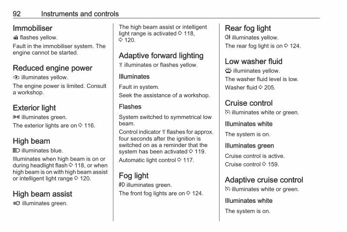
92 Instruments and controls
Immobiliserd flashes yellow.Fault in the immobiliser system. Theengine cannot be started.
Reduced engine power# illuminates yellow.The engine power is limited. Consulta workshop.
Exterior light8 illuminates green.The exterior lights are on 3 116.
High beamC illuminates blue.Illuminates when high beam is on orduring headlight flash 3 118, or whenhigh beam is on with high beam assistor intelligent light range 3 120.
High beam assistl illuminates green.
The high beam assist or intelligentlight range is activated 3 118,3 120.
Adaptive forward lightingf illuminates or flashes yellow.
IlluminatesFault in system.Seek the assistance of a workshop.
FlashesSystem switched to symmetrical lowbeam.Control indicator f flashes for approx.four seconds after the ignition isswitched on as a reminder that thesystem has been activated 3 119.Automatic light control 3 117.
Fog light> illuminates green.The front fog lights are on 3 124.
Rear fog lightr illuminates yellow.The rear fog light is on 3 124.
Low washer fluidG illuminates yellow.The washer fluid level is low.Washer fluid 3 205.
Cruise controlm illuminates white or green.
Illuminates whiteThe system is on.
Illuminates greenCruise control is active.Cruise control 3 159.
Adaptive cruise controlm illuminates white or green.
Illuminates whiteThe system is on.
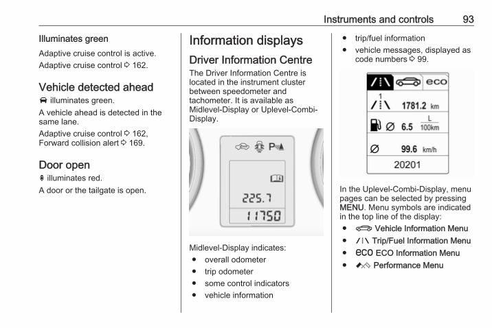
Instruments and controls 93
Illuminates greenAdaptive cruise control is active.Adaptive cruise control 3 162.
Vehicle detected aheadA illuminates green.A vehicle ahead is detected in thesame lane.Adaptive cruise control 3 162,Forward collision alert 3 169.
Door openh illuminates red.A door or the tailgate is open.
Information displaysDriver Information CentreThe Driver Information Centre islocated in the instrument clusterbetween speedometer andtachometer. It is available asMidlevel-Display or Uplevel-Combi-Display.
Midlevel-Display indicates:● overall odometer● trip odometer● some control indicators● vehicle information
● trip/fuel information● vehicle messages, displayed as
code numbers 3 99.
In the Uplevel-Combi-Display, menupages can be selected by pressingMENU. Menu symbols are indicatedin the top line of the display:● X Vehicle Information Menu● W Trip/Fuel Information Menu● s ECO Information Menu● C Performance Menu
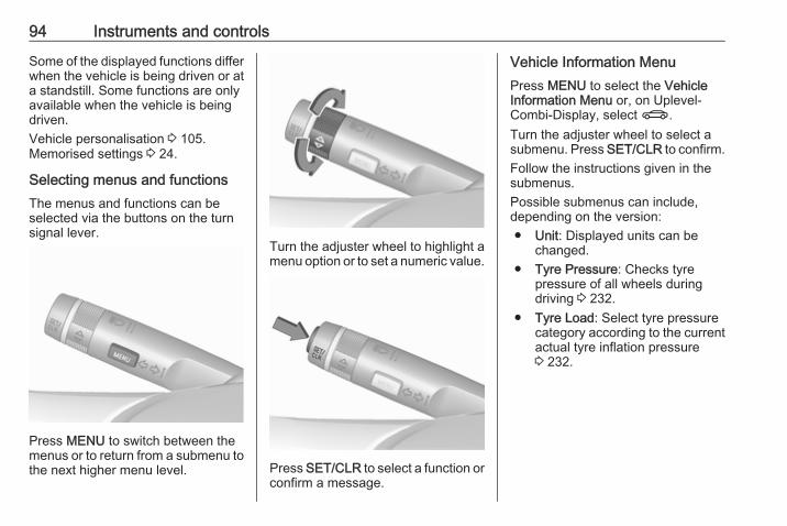
94 Instruments and controls
Some of the displayed functions differwhen the vehicle is being driven or ata standstill. Some functions are onlyavailable when the vehicle is beingdriven.Vehicle personalisation 3 105.Memorised settings 3 24.
Selecting menus and functionsThe menus and functions can beselected via the buttons on the turnsignal lever.
Press MENU to switch between themenus or to return from a submenu tothe next higher menu level.
Turn the adjuster wheel to highlight amenu option or to set a numeric value.
Press SET/CLR to select a function orconfirm a message.
Vehicle Information MenuPress MENU to select the VehicleInformation Menu or, on Uplevel-Combi-Display, select X.Turn the adjuster wheel to select asubmenu. Press SET/CLR to confirm.Follow the instructions given in thesubmenus.Possible submenus can include,depending on the version:● Unit: Displayed units can be
changed.● Tyre Pressure: Checks tyre
pressure of all wheels duringdriving 3 232.
● Tyre Load: Select tyre pressurecategory according to the currentactual tyre inflation pressure3 232.
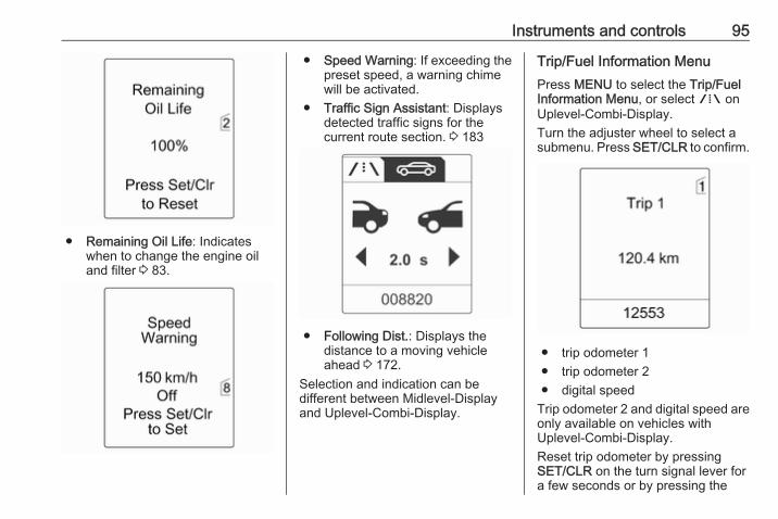
Instruments and controls 95
● Remaining Oil Life: Indicateswhen to change the engine oiland filter 3 83.
● Speed Warning: If exceeding thepreset speed, a warning chimewill be activated.
● Traffic Sign Assistant: Displaysdetected traffic signs for thecurrent route section. 3 183
● Following Dist.: Displays thedistance to a moving vehicleahead 3 172.
Selection and indication can bedifferent between Midlevel-Displayand Uplevel-Combi-Display.
Trip/Fuel Information MenuPress MENU to select the Trip/FuelInformation Menu, or select W onUplevel-Combi-Display.Turn the adjuster wheel to select asubmenu. Press SET/CLR to confirm.
● trip odometer 1● trip odometer 2● digital speed
Trip odometer 2 and digital speed areonly available on vehicles withUplevel-Combi-Display.Reset trip odometer by pressingSET/CLR on the turn signal lever fora few seconds or by pressing the
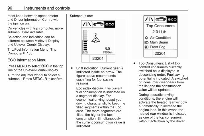
96 Instruments and controls
reset knob between speedometerand Driver Information Centre withthe ignition on.On vehicles with trip computer, moresubmenus are available.Selection and indication can bedifferent between Midlevel-Displayand Uplevel-Combi-Display.Trip/Fuel Information Menu, TripComputer 3 103.
ECO Information MenuPress MENU to select s in the topline of the Uplevel-Combi-Display.Turn the adjuster wheel to select asubmenu. Press SET/CLR to confirm.
Submenus are:
● Shift indication: Current gear isindicated inside an arrow. Thefigure above recommendsupshifting for fuel savingreasons.Eco index display: The currentfuel consumption is indicated ona segment display. Foreconomical driving, adapt yourdriving characteristic to keep thefilled segments within the Ecoarea. The more segments arefilled, the higher the fuelconsumption. Simultaneouslythe current consumption value isindicated.
● Top Consumers: List of topcomfort consumers currentlyswitched on is displayed indescending order. Fuel savingpotential is indicated. A switchedoff consumer disappears fromthe list and the consumptionvalue will be updated.During sporadic drivingconditions, the engine willactivate the heated rear windowautomatically to increase theengine load. In this event, theheated rear window is indicatedas one of the top consumers,without activation by the driver.
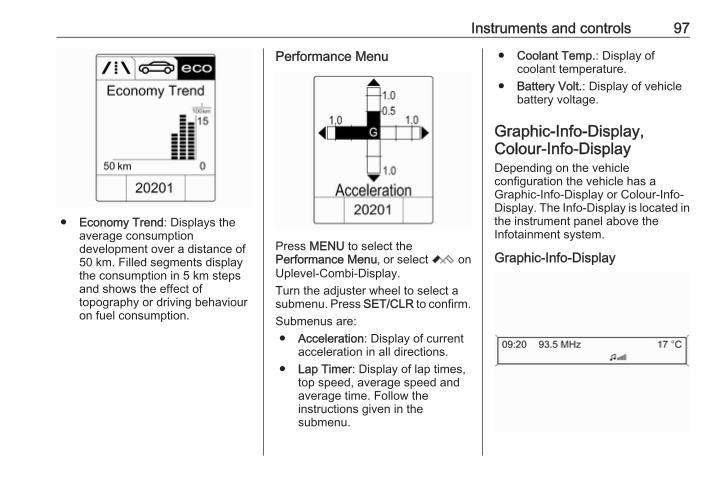
Instruments and controls 97
● Economy Trend: Displays theaverage consumptiondevelopment over a distance of50 km. Filled segments displaythe consumption in 5 km stepsand shows the effect oftopography or driving behaviouron fuel consumption.
Performance Menu
Press MENU to select thePerformance Menu, or select C onUplevel-Combi-Display.Turn the adjuster wheel to select asubmenu. Press SET/CLR to confirm.Submenus are:● Acceleration: Display of current
acceleration in all directions.● Lap Timer: Display of lap times,
top speed, average speed andaverage time. Follow theinstructions given in thesubmenu.
● Coolant Temp.: Display ofcoolant temperature.
● Battery Volt.: Display of vehiclebattery voltage.
Graphic-Info-Display,Colour-Info-DisplayDepending on the vehicleconfiguration the vehicle has aGraphic-Info-Display or Colour-Info-Display. The Info-Display is located inthe instrument panel above theInfotainment system.
Graphic-Info-Display
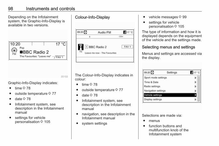
98 Instruments and controls
Depending on the Infotainmentsystem, the Graphic-Info-Display isavailable in two versions.
Graphic-Info-Display indicates:● time 3 78● outside temperature 3 77● date 3 78● Infotainment system, see
description in the Infotainmentmanual
● settings for vehiclepersonalisation 3 105
Colour-Info-Display
The Colour-Info-Display indicates incolour:● time 3 78● outside temperature 3 77● date 3 78● Infotainment system, see
description in the Infotainmentmanual
● navigation, see description in theInfotainment manual
● system settings
● vehicle messages 3 99● settings for vehicle
personalisation 3 105The type of information and how it isdisplayed depends on the equipmentof the vehicle and the settings made.
Selecting menus and settingsMenus and settings are accessed viathe display.
Selections are made via:● menus● function buttons and
multifunction knob of theInfotainment system
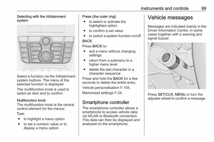
Instruments and controls 99
Selecting with the Infotainmentsystem
Select a function via the Infotainmentsystem buttons. The menu of theselected function is displayed.The multifunction knob is used toselect an item and to confirm.
Multifunction knobThe multifunction knob is the centralcontrol element for the menus:Turn● to highlight a menu option● to set a numeric value or to
display a menu option
Press (the outer ring)● to select or activate the
highlighted option● to confirm a set value● to switch a system function on/off
BACKPress BACK to:● exit a menu without changing
settings● return from a submenu to a
higher menu level● delete the last character in a
character sequencePress and hold the BACK for a fewseconds to delete the entire entry.Vehicle personalisation 3 105.Memorised settings 3 24.
Smartphone controllerThe smartphone controller allows asmartphone to access vehicle datavia WLAN or Bluetooth connection.This data can then be displayed andanalysed on the smartphone.
Vehicle messagesMessages are indicated mainly in theDriver Information Centre, in somecases together with a warning andsignal buzzer.
Press SET/CLR, MENU or turn theadjuster wheel to confirm a message.

100 Instruments and controls
Vehicle messages on theMidlevel-Display
The vehicle messages are displayedas code numbers.
No. Vehicle message
2 No radio remote controldetected, depress clutch pedalto restart
4 Air conditioning off
5 Steering wheel is locked
6 Depress brake pedal to releaseelectric parking brake
No. Vehicle message
7 Turn steering wheel, switchignition off then on
9 Turn steering wheel, restartengine
12 Vehicle overloaded
13 Compressor overheated
15 Centre high-mounted brakelight failure
16 Brake light failure
17 Headlight levelling malfunction
18 Left low beam failure
19 Rear fog light failure
20 Right low beam failure
21 Left sidelight failure
22 Right sidelight failure
23 Reversing light failure
24 Number plate light failure
25 Left front turn signal failure
No. Vehicle message
26 Left rear turn signal failure
27 Right front turn signal failure
28 Right rear turn signal failure
29 Check trailer brake light
30 Check trailer reversing light
31 Check left trailer turn signal
32 Check right trailer turn signal
33 Check trailer rear fog light
34 Check trailer rear light
35 Replace battery in radio remotecontrol
48 Clean side blind spot alertsystem
49 Lane departure warningunavailable
53 Tighten fuel filler cap
54 Water in diesel fuel filter
55 Diesel particle filter is full3 145
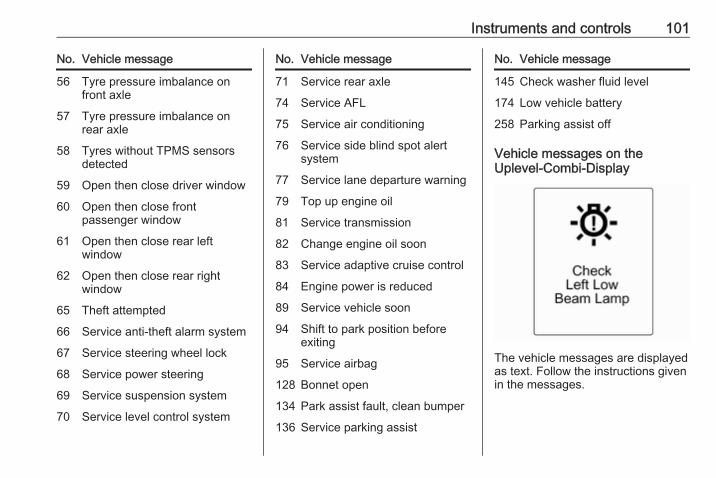
Instruments and controls 101
No. Vehicle message
56 Tyre pressure imbalance onfront axle
57 Tyre pressure imbalance onrear axle
58 Tyres without TPMS sensorsdetected
59 Open then close driver window
60 Open then close frontpassenger window
61 Open then close rear leftwindow
62 Open then close rear rightwindow
65 Theft attempted
66 Service anti-theft alarm system
67 Service steering wheel lock
68 Service power steering
69 Service suspension system
70 Service level control system
No. Vehicle message
71 Service rear axle
74 Service AFL
75 Service air conditioning
76 Service side blind spot alertsystem
77 Service lane departure warning
79 Top up engine oil
81 Service transmission
82 Change engine oil soon
83 Service adaptive cruise control
84 Engine power is reduced
89 Service vehicle soon
94 Shift to park position beforeexiting
95 Service airbag
128 Bonnet open
134 Park assist fault, clean bumper
136 Service parking assist
No. Vehicle message
145 Check washer fluid level
174 Low vehicle battery
258 Parking assist off
Vehicle messages on theUplevel-Combi-Display
The vehicle messages are displayedas text. Follow the instructions givenin the messages.
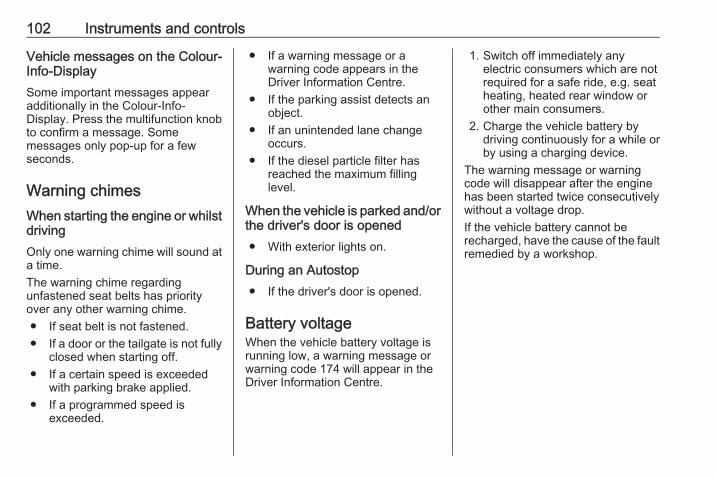
102 Instruments and controls
Vehicle messages on the Colour-Info-DisplaySome important messages appearadditionally in the Colour-Info-Display. Press the multifunction knobto confirm a message. Somemessages only pop-up for a fewseconds.
Warning chimesWhen starting the engine or whilstdrivingOnly one warning chime will sound ata time.The warning chime regardingunfastened seat belts has priorityover any other warning chime.● If seat belt is not fastened.● If a door or the tailgate is not fully
closed when starting off.● If a certain speed is exceeded
with parking brake applied.● If a programmed speed is
exceeded.
● If a warning message or awarning code appears in theDriver Information Centre.
● If the parking assist detects anobject.
● If an unintended lane changeoccurs.
● If the diesel particle filter hasreached the maximum fillinglevel.
When the vehicle is parked and/orthe driver's door is opened● With exterior lights on.
During an Autostop● If the driver's door is opened.
Battery voltageWhen the vehicle battery voltage isrunning low, a warning message orwarning code 174 will appear in theDriver Information Centre.
1. Switch off immediately anyelectric consumers which are notrequired for a safe ride, e.g. seatheating, heated rear window orother main consumers.
2. Charge the vehicle battery bydriving continuously for a while orby using a charging device.
The warning message or warningcode will disappear after the enginehas been started twice consecutivelywithout a voltage drop.If the vehicle battery cannot berecharged, have the cause of the faultremedied by a workshop.
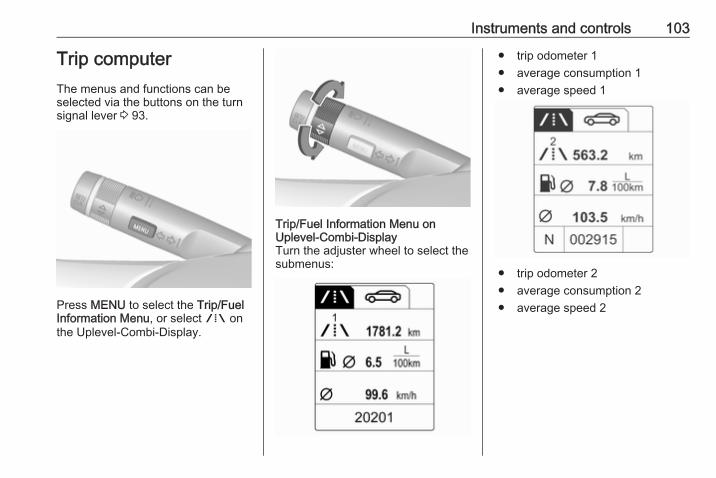
Instruments and controls 103
Trip computerThe menus and functions can beselected via the buttons on the turnsignal lever 3 93.
Press MENU to select the Trip/FuelInformation Menu, or select W onthe Uplevel-Combi-Display.
Trip/Fuel Information Menu onUplevel-Combi-DisplayTurn the adjuster wheel to select thesubmenus:
● trip odometer 1● average consumption 1● average speed 1
● trip odometer 2● average consumption 2● average speed 2

104 Instruments and controls
● digital speed● range● instantaneous consumption● route guidance
Trip computer 1 and 2The information of two trip computerscan be reset separately for odometer,average consumption and averagespeed by pressing SET/CLR, makingit possible to display different tripinformation for different drivers.
Trip odometerTrip odometer displays the recordeddistance since a certain reset.Trip odometer counts up to a distanceof 2000 km and then restarts at 0.To reset, press SET/CLR for a fewseconds.
RangeRange is calculated from current fueltank content and currentconsumption. The display showsaverage values.After refuelling, the range is updatedautomatically after a brief delay.
When the fuel level in the tank is low,a message appears on vehicles withUplevel-Combi-Display.When the tank needs to be refuelledimmediately, a warning code orwarning message is displayed onvehicles with Midlevel-Display orUplevel-Combi-Display.Additionally, control indicator iilluminates or flashes in the fuelgauge3 91.
Average consumptionDisplay of average consumption. Themeasurement can be reset at anytime and starts with a default value.To reset, press SET/CLR for a fewseconds.
Instantaneous consumptionDisplay of the instantaneousconsumption.
Average speedDisplay of average speed. Themeasurement can be reset at anytime.
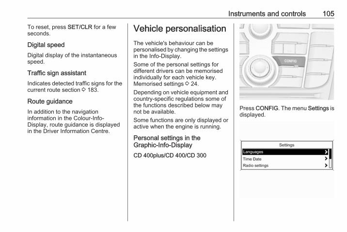
Instruments and controls 105
To reset, press SET/CLR for a fewseconds.
Digital speedDigital display of the instantaneousspeed.
Traffic sign assistantIndicates detected traffic signs for thecurrent route section 3 183.
Route guidanceIn addition to the navigationinformation in the Colour-Info-Display, route guidance is displayedin the Driver Information Centre.
Vehicle personalisationThe vehicle's behaviour can bepersonalised by changing the settingsin the Info-Display.Some of the personal settings fordifferent drivers can be memorisedindividually for each vehicle key.Memorised settings 3 24.Depending on vehicle equipment andcountry-specific regulations some ofthe functions described below maynot be available.Some functions are only displayed oractive when the engine is running.
Personal settings in theGraphic-Info-DisplayCD 400plus/CD 400/CD 300
Press CONFIG. The menu Settings isdisplayed.
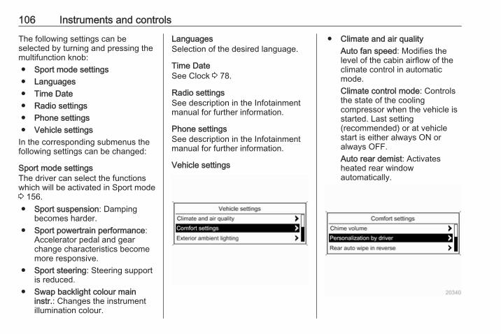
106 Instruments and controls
The following settings can beselected by turning and pressing themultifunction knob:● Sport mode settings● Languages● Time Date● Radio settings● Phone settings● Vehicle settings
In the corresponding submenus thefollowing settings can be changed:
Sport mode settingsThe driver can select the functionswhich will be activated in Sport mode3 156.● Sport suspension: Damping
becomes harder.● Sport powertrain performance:
Accelerator pedal and gearchange characteristics becomemore responsive.
● Sport steering: Steering supportis reduced.
● Swap backlight colour maininstr.: Changes the instrumentillumination colour.
LanguagesSelection of the desired language.
Time DateSee Clock 3 78.
Radio settingsSee description in the Infotainmentmanual for further information.
Phone settingsSee description in the Infotainmentmanual for further information.
Vehicle settings
● Climate and air qualityAuto fan speed: Modifies thelevel of the cabin airflow of theclimate control in automaticmode.Climate control mode: Controlsthe state of the coolingcompressor when the vehicle isstarted. Last setting(recommended) or at vehiclestart is either always ON oralways OFF.Auto rear demist: Activatesheated rear windowautomatically.
Instruments and controls 107
● Comfort settingsChime volume: Changes thevolume of warning chimes.Personalization by driver:Activates or deactivates thepersonalisation function.Rear auto wipe in reverse:Activates or deactivatesautomatic switching on of therear window wiper when reversegear is engaged.
● Park assist / Collision detectionPark assist: Activates ordeactivates the ultrasonicparking assist. Activation isselectable with or withoutattached trailer coupling.Auto collision preparation:Activates or deactivates theautomatic brake functionality ofthe vehicle in the event ofimminent collision danger. Thefollowing is selectable: thesystem will take over brakecontrol, warn by chimes only or isdeactivated.
Side blind zone alert: Changesthe settings for the side blind spotalert system.
● Exterior ambient lightingDuration upon exit of vehicle:Activates or deactivates andchanges the duration of exitlighting.Exterior lighting by unlocking:Activates or deactivates thewelcome lighting.
● Power door locksAuto door lock: Activates ordeactivates the automatic doorunlocking function after switchingoff ignition. Activates ordeactivates the automatic doorlocking function after driving-off.Stop door lock if door open:Activates or deactivates theautomatic door locking functionwhile a door is open.Delayed door lock: Activates ordeactivates the delayed doorlocking function.
● Remote locking, unlocking,starting
Remote unlock feedback:Activates or deactivates thehazard warning flasher feedbackwhilst unlocking.Remote door unlock: Changesthe configuration to unlock onlythe driver's door or the wholevehicle whilst unlocking.Auto relock doors: Activates ordeactivates the automatic relockfunction after unlocking withoutopening the vehicle.
● Restore factory settingsRestore factory settings: Resetsall settings to the default settings.
Settings in the Colour-Info-DisplayNavi 950/Navi 650/CD 600Press CONFIG on the Infotainmentsystem faceplate to enter theConfiguration menu.Turn the multifunction knob to scrollupwards or downwards in the list.Press the multifunction knob(Navi 950 / Navi 650: press the outerring) to select a menu item.
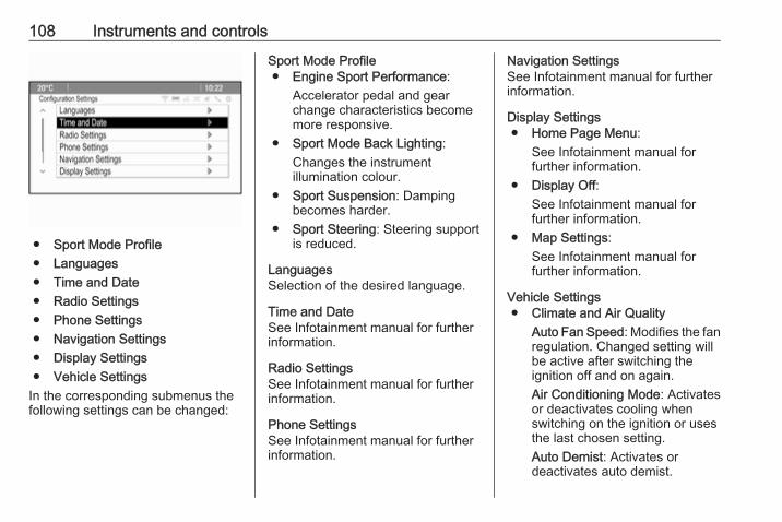
108 Instruments and controls
● Sport Mode Profile● Languages● Time and Date● Radio Settings● Phone Settings● Navigation Settings● Display Settings● Vehicle Settings
In the corresponding submenus thefollowing settings can be changed:
Sport Mode Profile● Engine Sport Performance:
Accelerator pedal and gearchange characteristics becomemore responsive.
● Sport Mode Back Lighting:Changes the instrumentillumination colour.
● Sport Suspension: Dampingbecomes harder.
● Sport Steering: Steering supportis reduced.
LanguagesSelection of the desired language.
Time and DateSee Infotainment manual for furtherinformation.
Radio SettingsSee Infotainment manual for furtherinformation.
Phone SettingsSee Infotainment manual for furtherinformation.
Navigation SettingsSee Infotainment manual for furtherinformation.
Display Settings● Home Page Menu:
See Infotainment manual forfurther information.
● Display Off:See Infotainment manual forfurther information.
● Map Settings:See Infotainment manual forfurther information.
Vehicle Settings● Climate and Air Quality
Auto Fan Speed: Modifies the fanregulation. Changed setting willbe active after switching theignition off and on again.Air Conditioning Mode: Activatesor deactivates cooling whenswitching on the ignition or usesthe last chosen setting.Auto Demist: Activates ordeactivates auto demist.
Instruments and controls 109
Auto Rear Demist: Activates theheated rear windowautomatically.
● Comfort and ConvenienceChime Volume: Changes thevolume of warning chimes.Personalisation by Driver:Activates or deactivates thepersonalisation function.Auto Reverse Gear Wiper:Activates or deactivatesautomatic switching on of therear window wiper when reversegear is engaged.
● Collision Detection SystemsPark Assist: Activates ordeactivates the ultrasonicsensors. Activation is selectablewith or without attached trailercoupling.Automatic Collision Preparation:Activates or deactivates theautomatic brake functionality ofthe vehicle in the event ofimminent collision danger. Thefollowing is selectable: thesystem will take over brake
control, warn by chimes only or isdeactivated completely.Side Blind Zone Alert: Activatesor deactivates the side blind spotalert system.
● LightingVehicle Locator Lights: Activatesor deactivates the entry lighting.Exit Lighting: Activates ordeactivates and changes theduration of exit lighting.
● Power Door LocksOpen Door Anti Lock Out:Activates or deactivates theautomatic door locking functionwhile a door is open.Auto Door Lock: Activates ordeactivates the automatic doorunlocking function after switchingoff ignition. Activates ordeactivates the automatic doorlocking function after driving-off.Delay Door Lock: Activates ordeactivates the delayed doorlocking function.
● Remote Lock/Unlock/StartRemote Lock Feedback:Activates or deactivates thehazard warning flasher feedbackwhilst locking.Remote Unlock Feedback:Activates or deactivates thehazard warning flasher feedbackwhilst unlocking.Remote Door Unlock: Changesthe configuration to unlock onlythe driver's door or the wholevehicle whilst unlocking.Relock Remotely UnlockedDoors: Activates or deactivatesthe automatic relock functionafter unlocking without openingthe vehicle.
● Return to Factory Settings?:Resets all settings to the defaultsettings.
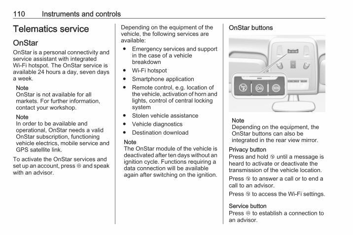
110 Instruments and controls
Telematics serviceOnStarOnStar is a personal connectivity andservice assistant with integratedWi-Fi hotspot. The OnStar service isavailable 24 hours a day, seven daysa week.NoteOnStar is not available for allmarkets. For further information,contact your workshop.NoteIn order to be available andoperational, OnStar needs a validOnStar subscription, functioningvehicle electrics, mobile service andGPS satellite link.
To activate the OnStar services andset up an account, press Z and speakwith an advisor.
Depending on the equipment of thevehicle, the following services areavailable:● Emergency services and support
in the case of a vehiclebreakdown
● Wi-Fi hotspot● Smartphone application● Remote control, e.g. location of
the vehicle, activation of horn andlights, control of central lockingsystem
● Stolen vehicle assistance● Vehicle diagnostics● Destination downloadNoteThe OnStar module of the vehicle isdeactivated after ten days without anignition cycle. Functions requiring adata connection will be availableagain after switching on the ignition.
OnStar buttons
NoteDepending on the equipment, theOnStar buttons can also beintegrated in the rear view mirror.
Privacy buttonPress and hold j until a message isheard to activate or deactivate thetransmission of the vehicle location.Press j to answer a call or to end acall to an advisor.Press j to access the Wi-Fi settings.
Service buttonPress Z to establish a connection toan advisor.
Instruments and controls 111
SOS buttonPress [ to establish a priorityemergency connection to a speciallytrained emergency advisor.
Status LEDGreen: The system is ready withactivated transmission of the vehiclelocation.Green flashing: The system is on acall.Red: A problem arose.Off: The system is ready withdeactivated transmission of thevehicle location or the system is instandby mode.Red / green flashing for a short periodof time: The transmission of thevehicle location has beendeactivated.
OnStar services
General servicesIf you need any information e.g.opening hours, points of interest anddestinations or if you need anysupport e.g. in the case of a vehicle
breakdown, a flat tyre and empty fueltank, press Z to establish aconnection to an advisor.
Emergency servicesIn the case of an emergency situation,press [ and talk to an advisor. Theadvisor then contacts emergency orassistance service providers anddirects them to your vehicle.In the case of an accident withactivation of airbags or belttensioners, an automatic emergencycall is established. The advisor isimmediately connected to yourvehicle to see whether help isneeded.
Wi-Fi hotspotThe Wi-Fi hotspot of the vehicleprovides internet connectivity with amaximum speed of 4G/LTE.NoteThe Wi-Fi hotspot functionality is notavailable for all markets.
Up to seven devices may beconnected.
To connect a mobile device with theWi-Fi hotspot:1. Press j and then select Wi-Fi
settings on the Info-Display. Thesettings displayed include the Wi-Fi hotspot name (SSID),password and connection type.
2. Start a Wi-Fi network search onyour mobile device.
3. Select your vehicle hotspot(SSID) when listed.
4. When prompted, enter thepassword on your mobile device.
NoteTo change the SSID or password,press Z and talk to an advisor or login to your account.
To switch off the Wi-Fi hotspotfunctionality, press Z to call anadvisor.
Smartphone appWith the myOpel smartphone app,some vehicle functions can beoperated remotely.
112 Instruments and controls
The following functions are available:● Lock or unlock vehicle.● Honk horn or flash lights.● Check fuel level, engine oil life
and tyre pressure (only with tyrepressure monitoring system).
● Send navigation destination tothe vehicle, if equipped with abuilt-in navigation system.
● Locate vehicle on a map.● Manage Wi-Fi settings.
To operate these functions, downloadthe app from App Store® orGoogle Play™ Store.
Remote controlIf desired, use any phone to call anadvisor, who can remotely operatespecific vehicle functions. Find therespective OnStar phone number onour country-specific website.The following functions are available:● Lock or unlock vehicle.● Provide information on the
vehicle location.● Honk horn or flash lights.
Stolen vehicle assistanceIf the vehicle is stolen, report the theftto the authorities and request OnStarstolen vehicle assistance. Use anyphone to call an advisor. Find therespective OnStar phone number onour country-specific website.OnStar can provide support inlocating and recovering the vehicle.Theft alertWhen the anti-theft alarm system istriggered, a notification is sent toOnStar. You are then informed aboutthis event by text message or email.Restart preventionBy sending remote signals, OnStarcan prevent the vehicle fromrestarting once it has been turned off.
On-demand diagnosticsAt any time e.g. if the vehicle displaysa vehicle message, press Z tocontact an advisor and ask tocomplete a real-time diagnostic checkto directly determine the issue.Depending on the results, the advisorwill provide further support.
Diagnostic reportThe vehicle automatically transmitsdiagnostic data to OnStar whichsends a monthly email report to youand your preferred workshop.NoteThe workshop notification functioncan be disabled in your account.
The report contains the status of keyoperating systems of the vehicle likeengine, transmission, airbags, ABS,and other major systems. It alsoprovides information on possiblemaintenance items and tyre pressure(only with tyre pressure monitoringsystem).To look at the information in greaterdetail, select the link within the emailand log in to your account.
Destination downloadA desired destination can be directlydownloaded to the navigation system.Press Z to call an advisor anddescribe the destination or point ofinterest.

Instruments and controls 113
The advisor can look up any addressor point of interest and directly sendthe destination to the built-innavigation system.
OnStar settings
OnStar PINTo have full access to all OnStarservices, a four-digit PIN is required.The PIN has to be personalised whenfirst talking to an advisor.To change the PIN, press Z to call anadvisor.
Account dataAn OnStar subscriber has an accountwhere all the data is stored. Torequest a change of the accountinformation, press Z and talk to anadvisor or log in to your account.If the OnStar service is used onanother vehicle, press Z and requestthat the account be transferred to thenew vehicle.
NoteIn any case, if the vehicle is disposedof, sold or otherwise transferred,immediately inform OnStar aboutthe changes and terminate theOnStar service on this vehicle.
Vehicle locationThe vehicle location is transmitted toOnStar when service is requested ortriggered. A message on the Info-Display informs about thistransmission.To activate or deactivate thetransmission of the vehicle location,press and hold j until an audiomessage is heard.The deactivation is indicated by thestatus light flashing red and green fora short period of time and each timethe vehicle is started.NoteIf the transmission of the vehiclelocation is deactivated, someservices are no longer available.NoteThe vehicle location always remainsaccessible to OnStar in the case ofan emergency.
Find the privacy policy in youraccount.
Software updatesOnStar may remotely carry outsoftware updates without furthernotice or consent. These updates areto enhance or maintain safety andsecurity or the operation of thevehicle.These updates may concern privacyissues. Find the privacy policy in youraccount.
ERA GLONASSERA GLONASS is a manually orautomatically actuated emergencyservice. Emergency centres provideassistance and information during anemergency.In case of an accident with activationof airbags or belt tensioners, anemergency call is placedautomatically. An immediateconnection with an advisor will beestablished who will check whetherhelp is needed.
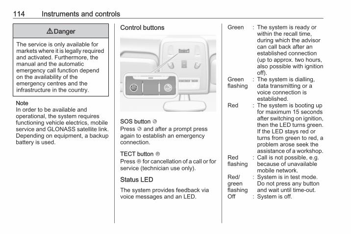
114 Instruments and controls
9 Danger
The service is only available formarkets where it is legally requiredand activated. Furthermore, themanual and the automaticemergency call function dependon the availability of theemergency centres and theinfrastructure in the country.
NoteIn order to be available andoperational, the system requiresfunctioning vehicle electrics, mobileservice and GLONASS satellite link.Depending on equipment, a backupbattery is used.
Control buttons
SOS button KPress K and after a prompt pressagain to establish an emergencyconnection.
TECT button JPress J for cancellation of a call or forservice (technician use only).
Status LEDThe system provides feedback viavoice messages and an LED.
Green : The system is ready orwithin the recall time,during which the advisorcan call back after anestablished connection(up to approx. two hours,also possible with ignitionoff).
Greenflashing
: The system is dialling,data transmitting or avoice connection isestablished.
Red : The system is booting upfor maximum 15 secondsafter switching on ignition,then the LED turns green.If the LED stays red orturns from green to red, aproblem arose seek theassistance of a workshop.
Redflashing
: Call is not possible, e.g.because of unavailablemobile network.
Red/greenflashing
: System is in test mode.Do not press any buttonand wait until time-out.
Off : System is off.
Instruments and controls 115
NoteIn very cold conditions it may take awhile to warm up the backup battery.When operational, the red LED turnsgreen.
Seek the assistance of a workshop ifthe LED does not illuminate afterswitching on the ignition.

116 Lighting
Lighting
Exterior lighting .......................... 116Light switch .............................. 116Automatic light control ............. 117High beam ............................... 118High beam assist ..................... 118Headlight flash ......................... 118Headlight range adjustment .... 119Headlights when drivingabroad .................................... 119
Daytime running lights ............. 120Adaptive forward lighting ......... 120Hazard warning flashers .......... 123Turn and lane-change signals . 123Front fog lights ......................... 124Rear fog lights ......................... 124Parking lights ........................... 124Reversing lights ....................... 125Misted light covers ................... 125
Interior lighting ........................... 125Instrument panel illuminationcontrol ..................................... 125
Interior lights ............................ 125Reading lights .......................... 126Sunvisor lights ......................... 126
Lighting features ........................ 127Centre console lighting ............ 127Entry lighting ............................ 127Exit lighting .............................. 127Battery discharge protection .... 128
Exterior lightingLight switch
Turn light switch:7 : lights off8 : sidelights9 : low beam
Control indicator 8 3 92.

Lighting 117
Light switch with automatic lightcontrol
Turn light switch:AUTO : automatic light control: low
beam is switched on and offautomatically depending onexternal lighting conditions
m : activation or deactivation ofthe automatic light control.Switch turns back to AUTO
8 : sidelights9 : low beam
In the Driver Information Centre withUplevel-Combi-Display, the currentstatus of the automatic light control isdisplayed.
When switching on the ignition,automatic light control is active.When low beam is on, 8 illuminates.Control indicator 8 3 92.
Tail lightsTail lights are illuminated togetherwith low/high beam and sidelights.
Automatic light control
When the automatic light controlfunction is switched on and theengine is running, the systemswitches between daytime runninglight and headlights automatically
depending on the lighting conditionsand information given by the rainsensor system.Daytime running light 3 120.
Automatic headlight activationDuring poor lighting conditions theheadlights are switched on.Furthermore the headlights areswitched on if the windscreen wipershave been activated for severalwipes.
Tunnel detectionWhen a tunnel is entered theheadlights are switched onimmediately.Adaptive forward lighting 3 120.
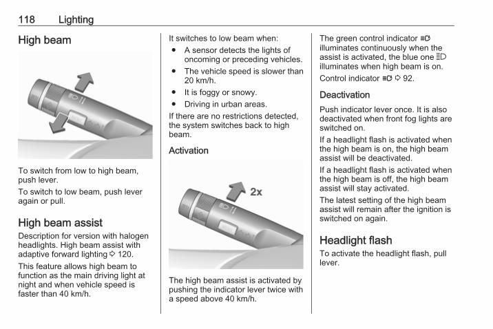
118 Lighting
High beam
To switch from low to high beam,push lever.To switch to low beam, push leveragain or pull.
High beam assistDescription for version with halogenheadlights. High beam assist withadaptive forward lighting 3 120.This feature allows high beam tofunction as the main driving light atnight and when vehicle speed isfaster than 40 km/h.
It switches to low beam when:● A sensor detects the lights of
oncoming or preceding vehicles.● The vehicle speed is slower than
20 km/h.● It is foggy or snowy.● Driving in urban areas.
If there are no restrictions detected,the system switches back to highbeam.
Activation
The high beam assist is activated bypushing the indicator lever twice witha speed above 40 km/h.
The green control indicator lilluminates continuously when theassist is activated, the blue one 7illuminates when high beam is on.Control indicator l 3 92.
DeactivationPush indicator lever once. It is alsodeactivated when front fog lights areswitched on.If a headlight flash is activated whenthe high beam is on, the high beamassist will be deactivated.If a headlight flash is activated whenthe high beam is off, the high beamassist will stay activated.The latest setting of the high beamassist will remain after the ignition isswitched on again.
Headlight flashTo activate the headlight flash, pulllever.
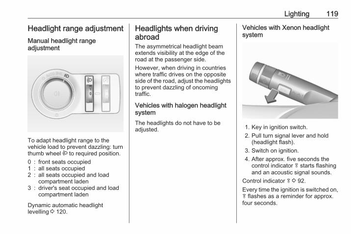
Lighting 119
Headlight range adjustmentManual headlight rangeadjustment
To adapt headlight range to thevehicle load to prevent dazzling: turnthumb wheel ? to required position.0 : front seats occupied1 : all seats occupied2 : all seats occupied and load
compartment laden3 : driver's seat occupied and load
compartment laden
Dynamic automatic headlightlevelling 3 120.
Headlights when drivingabroadThe asymmetrical headlight beamextends visibility at the edge of theroad at the passenger side.However, when driving in countrieswhere traffic drives on the oppositeside of the road, adjust the headlightsto prevent dazzling of oncomingtraffic.
Vehicles with halogen headlightsystemThe headlights do not have to beadjusted.
Vehicles with Xenon headlightsystem
1. Key in ignition switch.2. Pull turn signal lever and hold
(headlight flash).3. Switch on ignition.4. After approx. five seconds the
control indicator f starts flashingand an acoustic signal sounds.
Control indicator f 3 92.Every time the ignition is switched on,f flashes as a reminder for approx.four seconds.
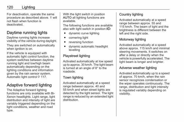
120 Lighting
For deactivation, operate the sameprocedure as described above. f willnot flash when function isdeactivated.
Daytime running lightsDaytime running lights increasevisibility of the vehicle during daylight.They are switched on automaticallywhen ignition is on.If the vehicle is equipped withautomatic light control function, thesystem switches between daytimerunning light and low/high beamautomatically depending on thelighting conditions and informationgiven by the rain sensor system.Automatic light control 3 117.
Adaptive forward lightingThe Adaptive forward lightingfunctions are only available with Bi-Xenon headlights. Light range, lightdistribution and intensity of light arevariably triggered depending on thelight conditions, weather and roadtype.
With the light switch in positionAUTO all lighting functions areavailable.The following functions are availablealso with light switch in position 9:● dynamic curve lighting● cornering light● reversing function● dynamic automatic headlight
levelling
Playstreet lightingActivated automatically at low speedup to approx. 30 km/h. The light beamis turned at an angle of 8° to theroadside.
Town lightingActivated automatically at a speedrange between approx. 40 and55 km/h and when street lights aredetected by the light sensor. The lightrange is reduced by an extended lightdistribution.
Country lightingActivated automatically at a speedrange between approx. 55 and115 km/h. The beam of light and thebrightness is different between theleft and the right side.
Motorway lightingActivated automatically at a speedabove approx. 115 km/h and minimalsteering movements. It switches onafter a delay or directly when thevehicle is powerfully accelerated. Thelight beam is longer and brighter.
Adverse weather lightingActivated automatically up to a speedof approx. 70 km/h, when the rainsensor recognizes condensation orthe wiper operates continuously. Therange, distribution and light intensityis regulated variably depending onvisibility.
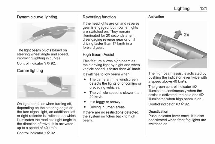
Lighting 121
Dynamic curve lighting
The light beam pivots based onsteering wheel angle and speed,improving lighting in curves.Control indicator f 3 92.
Corner lighting
On tight bends or when turning off,depending on the steering angle orthe turn signal light, an additional leftor right reflector is switched on whichilluminates the road at a right angle tothe direction of travel. It is activatedup to a speed of 40 km/h.Control indicator f 3 92.
Reversing functionIf the headlights are on and reversegear is engaged, both corner lightsare switched on. They remainilluminated for 20 seconds afterdisengaging reverse gear or untildriving faster than 17 km/h in aforward gear.
High Beam AssistThis feature allows high beam asmain driving light by night and whenvehicle speed is faster than 40 km/h.It switches to low beam when:● The camera in the windscreen
detects the lights of oncoming orpreceding vehicles.
● The vehicle speed is slower than20 km/h.
● It is foggy or snowy.● Driving in urban areas.
If there are no restrictions detected,the system switches back to highbeam.
Activation
The high beam assist is activated bypushing the indicator lever twice witha speed above 40 km/h.The green control indicator lilluminates continuously when theassist is activated, the blue one 7illuminates when high beam is on.Control indicator l 3 92.
DeactivationPush indicator lever once. It is alsodeactivated when front fog lights areswitched on.
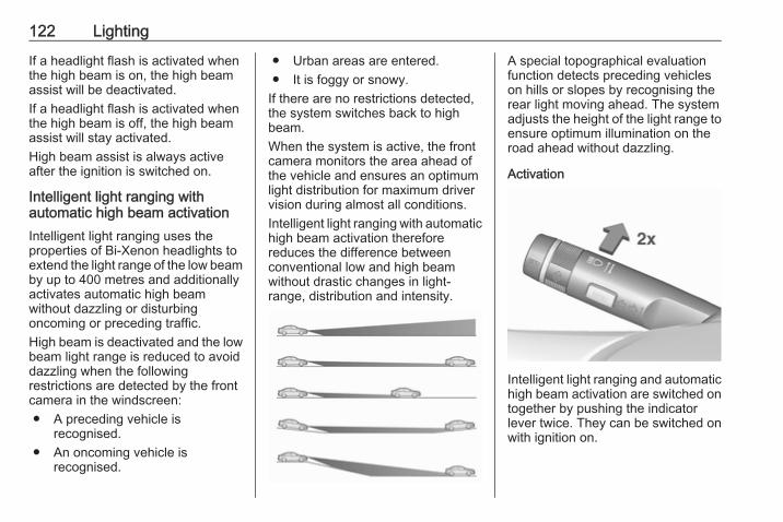
122 Lighting
If a headlight flash is activated whenthe high beam is on, the high beamassist will be deactivated.If a headlight flash is activated whenthe high beam is off, the high beamassist will stay activated.High beam assist is always activeafter the ignition is switched on.
Intelligent light ranging withautomatic high beam activationIntelligent light ranging uses theproperties of Bi-Xenon headlights toextend the light range of the low beamby up to 400 metres and additionallyactivates automatic high beamwithout dazzling or disturbingoncoming or preceding traffic.High beam is deactivated and the lowbeam light range is reduced to avoiddazzling when the followingrestrictions are detected by the frontcamera in the windscreen:● A preceding vehicle is
recognised.● An oncoming vehicle is
recognised.
● Urban areas are entered.● It is foggy or snowy.
If there are no restrictions detected,the system switches back to highbeam.When the system is active, the frontcamera monitors the area ahead ofthe vehicle and ensures an optimumlight distribution for maximum drivervision during almost all conditions.Intelligent light ranging with automatichigh beam activation thereforereduces the difference betweenconventional low and high beamwithout drastic changes in light-range, distribution and intensity.
A special topographical evaluationfunction detects preceding vehicleson hills or slopes by recognising therear light moving ahead. The systemadjusts the height of the light range toensure optimum illumination on theroad ahead without dazzling.
Activation
Intelligent light ranging and automatichigh beam activation are switched ontogether by pushing the indicatorlever twice. They can be switched onwith ignition on.
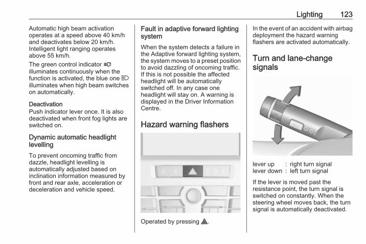
Lighting 123
Automatic high beam activationoperates at a speed above 40 km/hand deactivates below 20 km/h.Intelligent light ranging operatesabove 55 km/h.The green control indicator lilluminates continuously when thefunction is activated, the blue one 7illuminates when high beam switcheson automatically.
DeactivationPush indicator lever once. It is alsodeactivated when front fog lights areswitched on.
Dynamic automatic headlightlevellingTo prevent oncoming traffic fromdazzle, headlight levelling isautomatically adjusted based oninclination information measured byfront and rear axle, acceleration ordeceleration and vehicle speed.
Fault in adaptive forward lightingsystemWhen the system detects a failure inthe Adaptive forward lighting system,the system moves to a preset positionto avoid dazzling of oncoming traffic.If this is not possible the affectedheadlight will be automaticallyswitched off. In any case oneheadlight will stay on. A warning isdisplayed in the Driver InformationCentre.
Hazard warning flashers
Operated by pressing ¨.
In the event of an accident with airbagdeployment the hazard warningflashers are activated automatically.
Turn and lane-changesignals
lever up : right turn signallever down : left turn signal
If the lever is moved past theresistance point, the turn signal isswitched on constantly. When thesteering wheel moves back, the turnsignal is automatically deactivated.
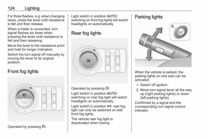
124 Lighting
For three flashes, e.g. when changinglanes, press the lever until resistanceis felt and then release.When a trailer is connected, turnsignal flashes six times whenpressing the lever until resistance isfelt and then releasing.Move the lever to the resistance pointand hold for longer indication.Switch the turn signal off manually bymoving the lever to its originalposition.
Front fog lights
Operated by pressing >.
Light switch in position AUTO:switching on front fog lights will switchheadlights on automatically.
Rear fog lights
Operated by pressing r.Light switch in position AUTO:switching on rear fog light will switchheadlights on automatically.Light switch in position 8: rear foglight can only be switched on withfront fog lights.The vehicle rear fog light isdeactivated when towing.
Parking lights
When the vehicle is parked, theparking lights on one side can beactivated:1. Switch off ignition.2. Move turn signal lever all the way
up (right parking lights) or down(left parking lights).
Confirmed by a signal and thecorresponding turn signal controlindicator.
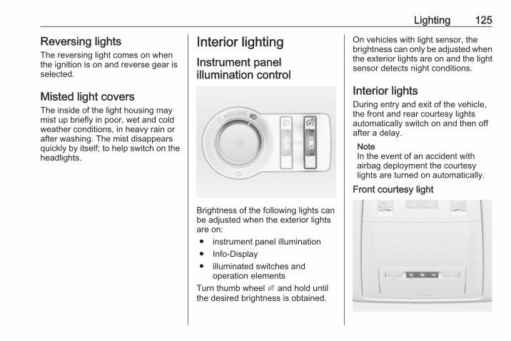
Lighting 125
Reversing lightsThe reversing light comes on whenthe ignition is on and reverse gear isselected.
Misted light coversThe inside of the light housing maymist up briefly in poor, wet and coldweather conditions, in heavy rain orafter washing. The mist disappearsquickly by itself; to help switch on theheadlights.
Interior lightingInstrument panelillumination control
Brightness of the following lights canbe adjusted when the exterior lightsare on:● instrument panel illumination● Info-Display● illuminated switches and
operation elementsTurn thumb wheel A and hold untilthe desired brightness is obtained.
On vehicles with light sensor, thebrightness can only be adjusted whenthe exterior lights are on and the lightsensor detects night conditions.
Interior lightsDuring entry and exit of the vehicle,the front and rear courtesy lightsautomatically switch on and then offafter a delay.NoteIn the event of an accident withairbag deployment the courtesylights are turned on automatically.
Front courtesy light
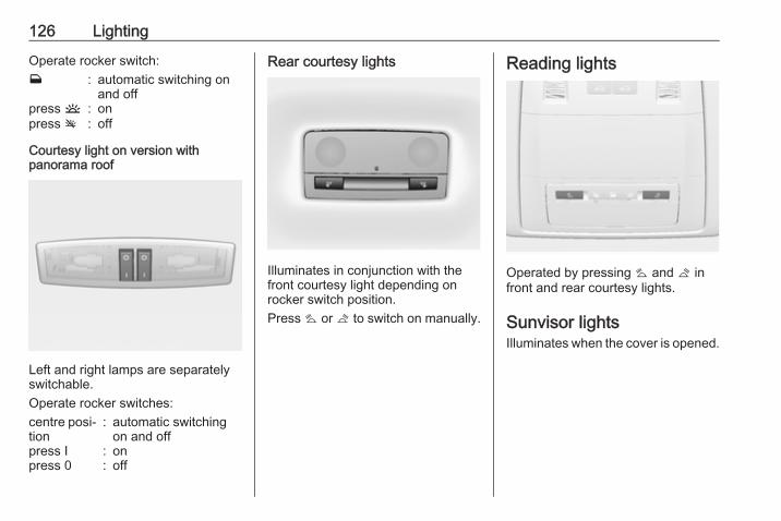
126 Lighting
Operate rocker switch:w : automatic switching on
and offpress u : onpress v : off
Courtesy light on version withpanorama roof
Left and right lamps are separatelyswitchable.Operate rocker switches:centre posi‐tion
: automatic switchingon and off
press I : onpress 0 : off
Rear courtesy lights
Illuminates in conjunction with thefront courtesy light depending onrocker switch position.Press s or t to switch on manually.
Reading lights
Operated by pressing s and t infront and rear courtesy lights.
Sunvisor lightsIlluminates when the cover is opened.
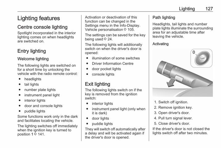
Lighting 127
Lighting featuresCentre console lightingSpotlight incorporated in the interiorlighting comes on when headlightsare switched on.
Entry lightingWelcome lightingThe following lights are switched onfor a short time by unlocking thevehicle with the radio remote control:● headlights● tail lights● number plate lights● instrument panel light● interior lights● door and console lights● puddle lights
Some functions work only in the darkand facilitates locating the vehicle.The lighting switches off immediatelywhen the ignition key is turned toposition 1 3 141.
Activation or deactivation of thisfunction can be changed in theSettings menu in the Info-Display.Vehicle personalisation 3 105.The settings can be saved for the keybeing used 3 24.The following lights will additionallyswitch on when the driver's door isopened:● illumination of some switches● Driver Information Centre● door pocket lights● console lights
Exit lightingThe following lights switch on if thekey is removed from the ignitionswitch:● interior lights● instrument panel light (only when
it is dark)● door lights● puddle lights
They will switch off automatically aftera delay and will be activated again ifthe driver's door is opened.
Path lightingHeadlights, tail lights and numberplate lights illuminate the surroundingarea for an adjustable time afterleaving the vehicle.
Activating
1. Switch off ignition.2. Remove ignition key.3. Open driver's door.4. Pull turn signal lever.5. Close driver's door.
If the driver's door is not closed thelights switch off after two minutes.
128 Lighting
Exit lighting is switched offimmediately if the turn signal lever ispulled while the driver's door is open.Activation, deactivation and durationof this function can be changed in theSettings menu in the Info-Display.Vehicle personalisation 3 105.The settings can be saved for the keybeing used 3 24.
Battery discharge protectionVehicle battery state of chargefunctionThe function guarantees longestvehicle battery life via a generatorwith controllable power output andoptimised power distribution.To prevent discharge of the vehiclebattery when driving, the followingsystems are reduced automatically intwo stages and finally switched off:● Auxiliary heater● Heated rear window and mirrors● Heated seats● Fan
In the second stage a message whichconfirms the activation of the vehiclebattery discharge protection will bedisplayed in the Driver InformationCentre.
Switching off electric lightsTo prevent discharge of the vehiclebattery when the ignition is switchedoff, some interior lights are switchedoff automatically after some time.
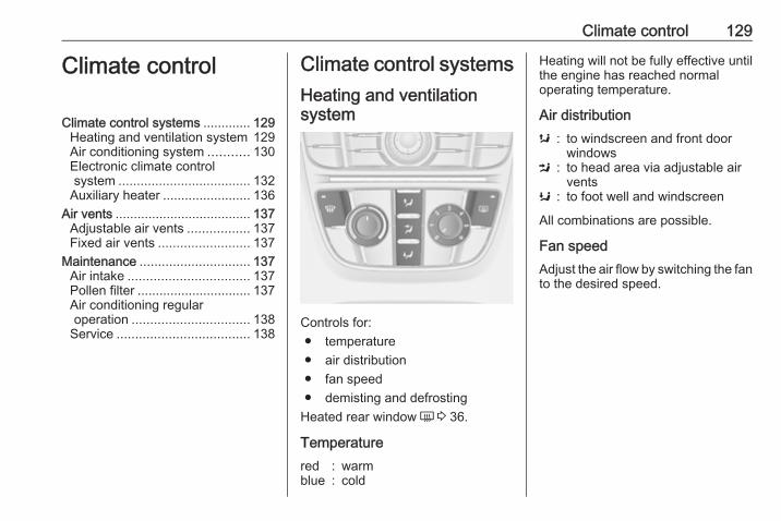
Climate control 129
Climate control
Climate control systems ............. 129Heating and ventilation system 129Air conditioning system ........... 130Electronic climate controlsystem .................................... 132
Auxiliary heater ........................ 136Air vents ..................................... 137
Adjustable air vents ................. 137Fixed air vents ......................... 137
Maintenance .............................. 137Air intake ................................. 137Pollen filter ............................... 137Air conditioning regularoperation ................................ 138
Service .................................... 138
Climate control systemsHeating and ventilationsystem
Controls for:● temperature● air distribution● fan speed● demisting and defrosting
Heated rear window Ü 3 36.
Temperaturered : warmblue : cold
Heating will not be fully effective untilthe engine has reached normaloperating temperature.
Air distributions : to windscreen and front door
windowsM : to head area via adjustable air
ventsK : to foot well and windscreen
All combinations are possible.
Fan speedAdjust the air flow by switching the fanto the desired speed.
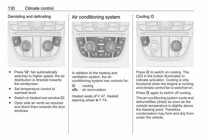
130 Climate control
Demisting and defrosting
● Press V: fan automaticallyswitches to higher speed, the airdistribution is directed towardsthe windscreen.
● Set temperature control towarmest level.
● Switch on heated rear window Ü.● Open side air vents as required
and direct them towards the doorwindows.
Air conditioning system
In addition to the heating andventilation system, the airconditioning system has controls for:n : cooling4 : air recirculation
Heated seats ß 3 47, Heatedsteering wheel * 3 74.
Cooling n
Press n to switch on cooling. TheLED in the button illuminates toindicate activation. Cooling is onlyfunctional when the engine is runningand climate control fan is switched on.Press n again to switch off cooling.The air conditioning system cools anddehumidifies (dries) as soon as theoutside temperature is slightly abovethe freezing point. Thereforecondensation may form and drip fromunder the vehicle.
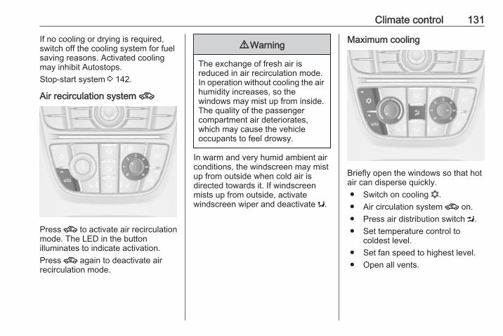
Climate control 131
If no cooling or drying is required,switch off the cooling system for fuelsaving reasons. Activated coolingmay inhibit Autostops.Stop-start system 3 142.
Air recirculation system 4
Press 4 to activate air recirculationmode. The LED in the buttonilluminates to indicate activation.Press 4 again to deactivate airrecirculation mode.
9 Warning
The exchange of fresh air isreduced in air recirculation mode.In operation without cooling the airhumidity increases, so thewindows may mist up from inside.The quality of the passengercompartment air deteriorates,which may cause the vehicleoccupants to feel drowsy.
In warm and very humid ambient airconditions, the windscreen may mistup from outside when cold air isdirected towards it. If windscreenmists up from outside, activatewindscreen wiper and deactivate s.
Maximum cooling
Briefly open the windows so that hotair can disperse quickly.● Switch on cooling n.● Air circulation system 4 on.● Press air distribution switch M.● Set temperature control to
coldest level.● Set fan speed to highest level.● Open all vents.
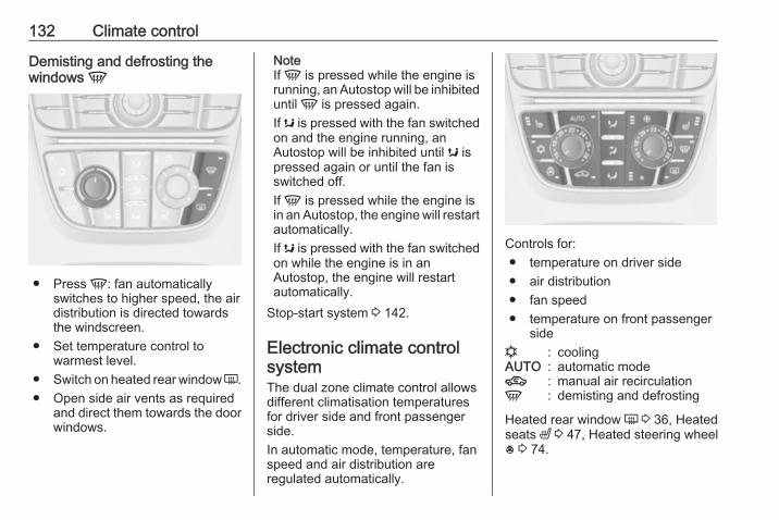
132 Climate control
Demisting and defrosting thewindows V
● Press V: fan automaticallyswitches to higher speed, the airdistribution is directed towardsthe windscreen.
● Set temperature control towarmest level.
● Switch on heated rear window Ü.● Open side air vents as required
and direct them towards the doorwindows.
NoteIf V is pressed while the engine isrunning, an Autostop will be inhibiteduntil V is pressed again.If s is pressed with the fan switchedon and the engine running, anAutostop will be inhibited until s ispressed again or until the fan isswitched off.If V is pressed while the engine isin an Autostop, the engine will restartautomatically.If s is pressed with the fan switchedon while the engine is in anAutostop, the engine will restartautomatically.
Stop-start system 3 142.
Electronic climate controlsystemThe dual zone climate control allowsdifferent climatisation temperaturesfor driver side and front passengerside.In automatic mode, temperature, fanspeed and air distribution areregulated automatically.
Controls for:● temperature on driver side● air distribution● fan speed● temperature on front passenger
siden : coolingAUTO : automatic mode4 : manual air recirculationV : demisting and defrosting
Heated rear window Ü 3 36, Heatedseats ß 3 47, Heated steering wheel* 3 74.
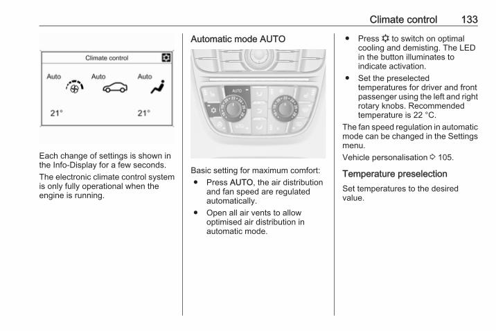
Climate control 133
Each change of settings is shown inthe Info-Display for a few seconds.The electronic climate control systemis only fully operational when theengine is running.
Automatic mode AUTO
Basic setting for maximum comfort:● Press AUTO, the air distribution
and fan speed are regulatedautomatically.
● Open all air vents to allowoptimised air distribution inautomatic mode.
● Press n to switch on optimalcooling and demisting. The LEDin the button illuminates toindicate activation.
● Set the preselectedtemperatures for driver and frontpassenger using the left and rightrotary knobs. Recommendedtemperature is 22 °C.
The fan speed regulation in automaticmode can be changed in the Settingsmenu.Vehicle personalisation 3 105.
Temperature preselectionSet temperatures to the desiredvalue.
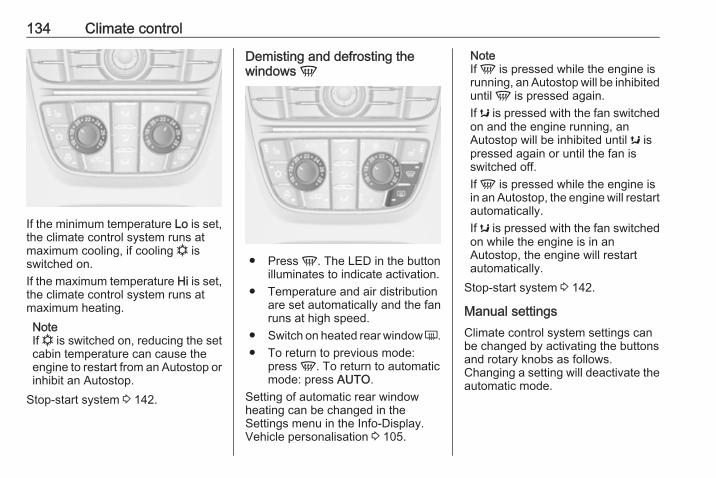
134 Climate control
If the minimum temperature Lo is set,the climate control system runs atmaximum cooling, if cooling n isswitched on.If the maximum temperature Hi is set,the climate control system runs atmaximum heating.NoteIf n is switched on, reducing the setcabin temperature can cause theengine to restart from an Autostop orinhibit an Autostop.
Stop-start system 3 142.
Demisting and defrosting thewindows V
● Press V. The LED in the buttonilluminates to indicate activation.
● Temperature and air distributionare set automatically and the fanruns at high speed.
● Switch on heated rear window Ü.● To return to previous mode:
press V. To return to automaticmode: press AUTO.
Setting of automatic rear windowheating can be changed in theSettings menu in the Info-Display.Vehicle personalisation 3 105.
NoteIf V is pressed while the engine isrunning, an Autostop will be inhibiteduntil V is pressed again.If s is pressed with the fan switchedon and the engine running, anAutostop will be inhibited until s ispressed again or until the fan isswitched off.If V is pressed while the engine isin an Autostop, the engine will restartautomatically.If s is pressed with the fan switchedon while the engine is in anAutostop, the engine will restartautomatically.
Stop-start system 3 142.
Manual settingsClimate control system settings canbe changed by activating the buttonsand rotary knobs as follows.Changing a setting will deactivate theautomatic mode.
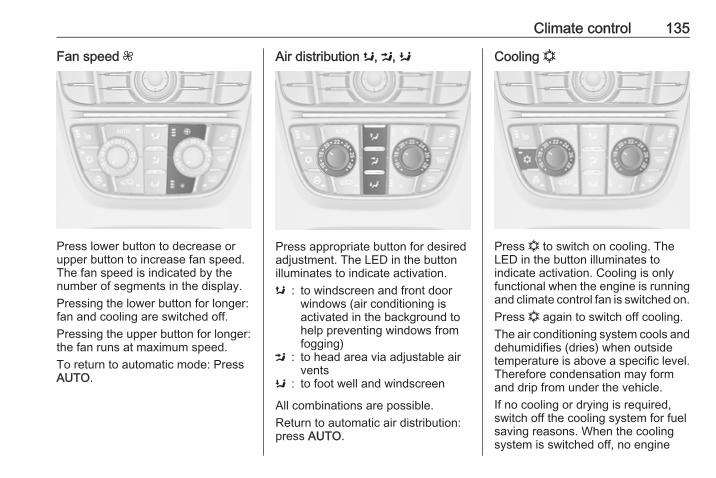
Climate control 135
Fan speed Z
Press lower button to decrease orupper button to increase fan speed.The fan speed is indicated by thenumber of segments in the display.Pressing the lower button for longer:fan and cooling are switched off.Pressing the upper button for longer:the fan runs at maximum speed.To return to automatic mode: PressAUTO.
Air distribution s, M, K
Press appropriate button for desiredadjustment. The LED in the buttonilluminates to indicate activation.s : to windscreen and front door
windows (air conditioning isactivated in the background tohelp preventing windows fromfogging)
M : to head area via adjustable airvents
K : to foot well and windscreen
All combinations are possible.Return to automatic air distribution:press AUTO.
Cooling n
Press n to switch on cooling. TheLED in the button illuminates toindicate activation. Cooling is onlyfunctional when the engine is runningand climate control fan is switched on.Press n again to switch off cooling.The air conditioning system cools anddehumidifies (dries) when outsidetemperature is above a specific level.Therefore condensation may formand drip from under the vehicle.If no cooling or drying is required,switch off the cooling system for fuelsaving reasons. When the coolingsystem is switched off, no engine
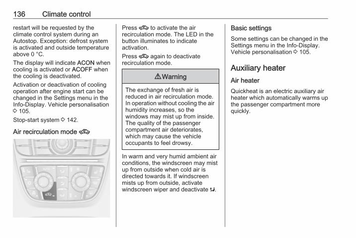
136 Climate control
restart will be requested by theclimate control system during anAutostop. Exception: defrost systemis activated and outside temperatureabove 0 °C.The display will indicate ACON whencooling is activated or ACOFF whenthe cooling is deactivated.Activation or deactivation of coolingoperation after engine start can bechanged in the Settings menu in theInfo-Display. Vehicle personalisation3 105.Stop-start system 3 142.
Air recirculation mode 4
Press 4 to activate the airrecirculation mode. The LED in thebutton illuminates to indicateactivation.Press 4 again to deactivaterecirculation mode.
9 Warning
The exchange of fresh air isreduced in air recirculation mode.In operation without cooling the airhumidity increases, so thewindows may mist up from inside.The quality of the passengercompartment air deteriorates,which may cause the vehicleoccupants to feel drowsy.
In warm and very humid ambient airconditions, the windscreen may mistup from outside when cold air isdirected towards it. If windscreenmists up from outside, activatewindscreen wiper and deactivate s.
Basic settingsSome settings can be changed in theSettings menu in the Info-Display.Vehicle personalisation 3 105.
Auxiliary heaterAir heaterQuickheat is an electric auxiliary airheater which automatically warms upthe passenger compartment morequickly.
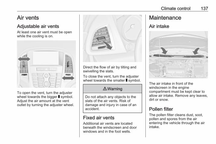
Climate control 137
Air ventsAdjustable air ventsAt least one air vent must be openwhile the cooling is on.
To open the vent, turn the adjusterwheel towards the bigger W symbol.Adjust the air amount at the ventoutlet by turning the adjuster wheel.
Direct the flow of air by tilting andswivelling the slats.To close the vent, turn the adjusterwheel towards the smaller W symbol.
9 Warning
Do not attach any objects to theslats of the air vents. Risk ofdamage and injury in case of anaccident.
Fixed air ventsAdditional air vents are locatedbeneath the windscreen and doorwindows and in the foot wells.
MaintenanceAir intake
The air intake in front of thewindscreen in the enginecompartment must be kept clear toallow air intake. Remove any leaves,dirt or snow.
Pollen filterThe pollen filter cleans dust, soot,pollen and spores from the airentering the vehicle through the airintake.
138 Climate control
Air conditioning regularoperationIn order to ensure continuouslyefficient performance, cooling mustbe operated for a few minutes once amonth, irrespective of the weatherand time of year. Operation withcooling is not possible when theoutside temperature is too low.
ServiceFor optimal cooling performance, it isrecommended to annually check theclimate control system, startingthree years after initial vehicleregistration, including:● functionality and pressure test● heating functionality● leakage check● check of drive belts● cleaning of condenser and
evaporator drainage● performance checkNoteRefrigerant R-134a containsfluorinated greenhouse gases.
Driving and operating 139
Driving andoperating
Driving hints ............................... 140Control of the vehicle ............... 140Steering ................................... 140
Starting and operating ............... 140New vehicle running-in ............ 140Ignition switch positions ........... 141Retained power off .................. 141Starting the engine .................. 141Overrun cut-off ........................ 142Stop-start system .................... 142Parking .................................... 144
Engine exhaust .......................... 145Diesel particle filter .................. 145Catalytic converter ................... 146
Automatic transmission .............. 147Transmission display ............... 147Selector lever .......................... 148Manual mode ........................... 149Electronic driving programmes 149Fault ........................................ 149Interruption of power supply .... 150
Manual transmission .................. 151
Brakes ........................................ 151Antilock brake system ............. 151Parking brake .......................... 152Brake assist ............................. 154Hill start assist ......................... 154
Ride control systems ................. 154Traction Control system .......... 154Electronic Stability Control ...... 155Interactive driving system ........ 156
Driver assistance systems ......... 159Cruise control .......................... 159Speed limiter ........................... 161Adaptive cruise control ............ 162Forward collision alert ............. 169Following distance indication ... 172Active Emergency Braking ...... 173Parking assist .......................... 175Side blind spot alert ................. 182Traffic sign assistant ................ 183Lane departure warning .......... 187
Fuel ............................................ 188Fuel for petrol engines ............. 188Fuel for diesel engines ............ 188Fuel for liquid gas operation .... 189Refuelling ................................ 191Fuel consumption - CO2-Emissions ............................... 194
Trailer hitch ................................ 195General information ................. 195
Driving characteristics andtowing tips .............................. 195
Trailer towing ........................... 195Towing equipment ................... 196Trailer stability assist ............... 199
140 Driving and operating
Driving hintsControl of the vehicleNever coast with engine notrunning (except during Autostop)Many systems will not function in thissituation (e.g. brake servo unit, powersteering). Driving in this manner is adanger to yourself and others. Allsystems function during an Autostop,but there will be a controlled reductionin power steering assist and vehiclespeed is reduced.Stop-start system 3 142.
Idle boostIf charging of the vehicle battery isrequired due to battery condition, thepower output of the generator mustbe increased. This will be achieved byan idle boost which may be audible.A message is displayed in the DriverInformation Centre.
PedalsTo ensure the pedal travel isuninhibited, there must be no mats inthe area of the pedals.Use only floor mats which fit properlyand are fixed by the retainers on thedriver's side.
SteeringIf power steering assist is lostbecause the engine stops or due to asystem malfunction, the vehicle canbe steered but may require increasedeffort.Control indicator c 3 89.
Caution
Vehicles equipped with hydraulicpower steering:If the steering wheel is turned untilit reaches the end of its travel, andis held in that position for morethan 15 seconds, damage mayoccur to the power steeringsystem and there may be loss ofpower steering assist.
Starting and operatingNew vehicle running-inDo not brake unnecessarily hard forthe first few journeys.During the first drive, smoke mayoccur because of wax and oilevaporating off the exhaust system.Park the vehicle in the open for awhile after the first drive and avoidinhaling the fumes.During the running-in period fuel andengine oil consumption may behigher and the cleaning process ofthe diesel particle filter may takeplace more often. Autostop may beinhibited to allow for charging thebattery.Diesel particle filter 3 145.
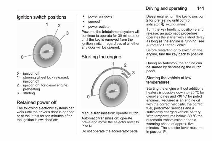
Driving and operating 141
Ignition switch positions
0 : ignition off1 : steering wheel lock released,
ignition off2 : ignition on, for diesel engine:
preheating3 : starting
Retained power offThe following electronic systems canwork until the driver's door is openedor at the latest for ten minutes afterthe ignition is switched off:
● power windows● sunroof● power outlets
Power to the Infotainment system willcontinue to operate for 30 minutes oruntil the key is removed from theignition switch, regardless of whetherany door will be opened.
Starting the engine
Manual transmission: operate clutch.Automatic transmission: operatebrake and move the selector lever toP or N.Do not operate the accelerator pedal.
Diesel engine: turn the key to position2 for preheating until controlindicator ! extinguishes.Turn the key briefly to position 3 andrelease: an automatic procedureoperates the starter with a short delayas long as the engine is running, seeAutomatic Starter Control.Before restarting or to switch off theengine, turn the key back to position0.During an Autostop, the engine canbe started by depressing the clutchpedal.
Starting the vehicle at lowtemperaturesStarting the engine without additionalheaters is possible down to -25 °С fordiesel engines and -30 °C for petrolengines. Required is an engine oilwith the correct viscosity, the correctfuel, performed services and asufficiently charged vehicle battery.With temperatures below -30 °C theautomatic transmission needs awarming phase of approx. fiveminutes. The selector lever must bein position P.

142 Driving and operating
Automatic Starter ControlThis function controls the enginestarting procedure. The driver doesnot need to hold the key in position 3.Once applied, the system will go onstarting automatically until the engineis running. Because of the checkingprocedure, the engine starts runningafter a short delay.Possible reasons for a non-startingengine:● Clutch pedal not operated
(manual transmission).● Brake pedal not operated or
selector lever not in P or N(automatic transmission).
● Timeout occurred.
Turbo engine warm-upUpon start-up, engine availabletorque may be limited for a short time,especially when the enginetemperature is cold. The limitation isto allow the lubrication system to fullyprotect the engine.
Overrun cut-offThe fuel supply is automatically cut offduring overrun, i.e. when the vehicleis driven with a gear engaged butaccelerator pedal is released.Depending on driving conditions, theoverrun cut-off may be deactivated.
Stop-start systemThe stop-start system helps to savefuel and to reduce the exhaustemissions. When conditions allow, itswitches off the engine as soon as thevehicle is at a low speed or at astandstill, e.g. at a traffic light or in atraffic jam. It starts the engineautomatically as soon as the clutch isdepressed. A battery sensor ensuresthat an Autostop is only performed ifthe vehicle battery is sufficientlycharged for a restart.
ActivationThe stop-start system is available assoon as the engine is started, thevehicle starts-off and the conditionsas stated below in this section arefulfilled.
Deactivation
Deactivate the stop-start systemmanually by pressing eco. Thedeactivation is indicated when theLED in the button extinguishes.
AutostopIf the vehicle is at a low speed or at astandstill, activate an Autostop asfollows:● Depress the clutch pedal.● Move the selector lever to
neutral.● Release the clutch pedal.

Driving and operating 143
The engine will be switched off whilethe ignition stays on.
An Autostop is indicated by theneedle at the AUTOSTOP position inthe tachometer.During an Autostop, the heating andbrake performance will bemaintained.
Caution
The power steering assist may bereduced during an Autostop.
Conditions for an AutostopThe stop-start system checks if eachof the following conditions is fulfilled:● The stop-start system is not
manually deactivated.● The bonnet is fully closed.● The driver's door is closed or the
driver's seat belt is fastened.● The vehicle battery is sufficiently
charged and in good condition.● The engine is warmed-up.● The engine coolant temperature
is not too high.● The engine exhaust temperature
is not too high, e.g. after drivingwith high engine load.
● The ambient temperature isabove -5 °C.
● The climate control systemallows an Autostop.
● The brake vacuum is sufficient.● The self-cleaning function of the
diesel particle filter is not active.● The vehicle was driven at least at
walking speed since the lastAutostop.
Otherwise an Autostop will beinhibited.Certain settings of the climate controlsystem may inhibit an Autostop. See"Climate control" chapter for moredetails 3 132.Immediately after motorway driving,an Autostop may be inhibited.New vehicle running-in 3 140.
Vehicle battery discharge protectionTo ensure reliable engine restarts,several battery discharge protectionfeatures are implemented as part ofthe stop-start system.
Power saving measuresDuring an Autostop, several electricfeatures, e.g. auxiliary electric heateror heated rear window are disabled orswitched into a power saving mode.The fan speed of the climate controlsystem is reduced to save power.
Restart of the engine by the driverDepress the clutch pedal to restart theengine.
144 Driving and operating
The engine start is indicated by theneedle at the idle speed position inthe tachometer.If the selector lever is shifted out ofneutral before depressing the clutchfirst, control indicator - illuminatesor is shown as a symbol in the DriverInformation Centre.Control indicator - 3 88.
Restart of the engine by the stop-start systemThe selector lever must be in neutralto enable an automatic restart.If one of the following conditionsoccurs during an Autostop, theengine will be restarted automaticallyby the stop-start system:● The stop-start system is
manually deactivated.● The bonnet is opened.● The driver's seat belt is
unfastened and the driver's dooris opened.
● The engine temperature is toolow.
● The charging level of the vehiclebattery is below a defined level.
● The brake vacuum is notsufficient.
● The vehicle is driven at least atwalking speed.
● The climate control systemrequests an engine start.
● The air conditioning is manuallyswitched on.
If the bonnet is not fully closed, awarning message is displayed in theDriver Information Centre.If an electric accessory, e.g. aportable CD player, is connected tothe power outlet, a brief power dropduring restart might be noticeable.
Parking
9 Warning
● Do not park the vehicle on aneasily ignitable surface. Thehigh temperature of theexhaust system could ignite thesurface.
● Always apply the parkingbrake. Activate the manualparking brake without pressingthe release button. Apply asfirmly as possible on a downhillslope or uphill slope. Depressbrake pedal at the same time toreduce operating force.For vehicles with electricparking brake, pull switch m forapprox. one second.The electric parking brake isapplied when control indicatorm illuminates 3 88.
● Switch off the engine.● If the vehicle is on a level
surface or uphill slope, engagefirst gear or set the selectorlever to position P beforeremoving the ignition key. Onan uphill slope, turn the frontwheels away from the kerb.If the vehicle is on a downhillslope, engage reverse gear orset the selector lever to positionP before removing the ignition
Driving and operating 145
key. Turn the front wheelstowards the kerb.
● Close the windows and thesunroof.
● Remove the ignition key fromthe ignition switch. Turn thesteering wheel until thesteering wheel lock is felt toengage.For vehicles with automatictransmission, the key can onlybe removed when the selectorlever is in position P.
● Lock the vehicle.● Activate the anti-theft alarm
system.● The engine cooling fans may run
after the engine has beenswitched off 3 202.
Caution
After running at high enginespeeds or with high engine loads,operate the engine briefly at a lowload or run in neutral for
approx. 30 seconds beforeswitching off, in order to protectthe turbocharger.
NoteIn the event of an accident withairbag deployment, the engine isturned off automatically if the vehiclecomes to a standstill within a certaintime.
Engine exhaust
9 Danger
Engine exhaust gases containpoisonous carbon monoxide,which is colourless and odourlessand could be fatal if inhaled.If exhaust gases enter the interiorof the vehicle, open the windows.Have the cause of the faultrectified by a workshop.Avoid driving with an open loadcompartment, otherwise exhaustgases could enter the vehicle.
Diesel particle filterThe diesel particle filter system filtersharmful soot particles out of theexhaust gases. The system includesa self-cleaning function that runsautomatically during driving withoutany notification. The filter is cleanedby periodically burning off the sootparticles at high temperature. Thisprocess takes place automaticallyunder set driving conditions and maytake up to 25 minutes. Typically it
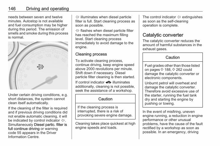
146 Driving and operating
needs between seven and twelveminutes. Autostop is not availableand fuel consumption may be higherduring this period. The emission ofsmells and smoke during this processis normal.
Under certain driving conditions, e.g.short distances, the system cannotclean itself automatically.If the cleaning of the filter is requiredand if previous driving conditions didnot enable automatic cleaning, it willbe indicated by control indicator %.Simultaneously Diesel partic. filter isfull continue driving or warningcode 55 appears in the DriverInformation Centre.
% illuminates when diesel particlefilter is full. Start cleaning process assoon as possible.% flashes when diesel particle filterhas reached the maximum fillinglevel. Start cleaning processimmediately to avoid damage to theengine.
Cleaning processTo activate cleaning process,continue driving, keep engine speedabove 2000 revolutions per minute.Shift down if necessary. Dieselparticle filter cleaning is then started.If control indicator g illuminatesadditionally, cleaning is not possible,seek the assistance of a workshop.
Caution
If the cleaning process isinterrupted, there is a risk ofprovoking severe engine damage.
Cleaning takes place quickest at highengine speeds and loads.
The control indicator % extinguishesas soon as the self-cleaningoperation is complete.
Catalytic converterThe catalytic converter reduces theamount of harmful substances in theexhaust gases.
Caution
Fuel grades other than those listedon pages 3 188, 3 262 coulddamage the catalytic converter orelectronic components.Unburnt petrol will overheat anddamage the catalytic converter.Therefore avoid excessive use ofthe starter, running the fuel tankdry and starting the engine bypushing or towing.
In the event of misfiring, unevenengine running, a reduction in engineperformance or other unusualproblems, have the cause of the faultrectified by a workshop as soon aspossible. In an emergency, driving

Driving and operating 147
can be continued for a short period,keeping vehicle speed and enginespeed low.
Automatic transmissionThe automatic transmission permitsautomatic gearshifting (automaticmode) or manual gearshifting(manual mode).Manual shifting is possible in manualmode by tapping the selector lever3 149.
Transmission display
The mode or selected gear is shownin the transmission display.
In automatic mode, the drivingprogramme is indicated by D in theDriver Information Centre.R indicates reverse gear.N indicates neutral position.P indicates park position.Midlevel display: in manual mode thenumber of the selected gear isindicated.
Uplevel display: in manual mode, Mand the number of the selected gearis indicated.
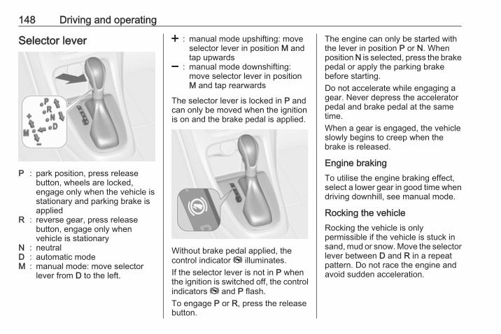
148 Driving and operating
Selector lever
P : park position, press releasebutton, wheels are locked,engage only when the vehicle isstationary and parking brake isapplied
R : reverse gear, press releasebutton, engage only whenvehicle is stationary
N : neutralD : automatic modeM : manual mode: move selector
lever from D to the left.
< : manual mode upshifting: moveselector lever in position M andtap upwards
] : manual mode downshifting:move selector lever in positionM and tap rearwards
The selector lever is locked in P andcan only be moved when the ignitionis on and the brake pedal is applied.
Without brake pedal applied, thecontrol indicator j illuminates.If the selector lever is not in P whenthe ignition is switched off, the controlindicators j and P flash.To engage P or R, press the releasebutton.
The engine can only be started withthe lever in position P or N. Whenposition N is selected, press the brakepedal or apply the parking brakebefore starting.Do not accelerate while engaging agear. Never depress the acceleratorpedal and brake pedal at the sametime.When a gear is engaged, the vehicleslowly begins to creep when thebrake is released.
Engine brakingTo utilise the engine braking effect,select a lower gear in good time whendriving downhill, see manual mode.
Rocking the vehicleRocking the vehicle is onlypermissible if the vehicle is stuck insand, mud or snow. Move the selectorlever between D and R in a repeatpattern. Do not race the engine andavoid sudden acceleration.
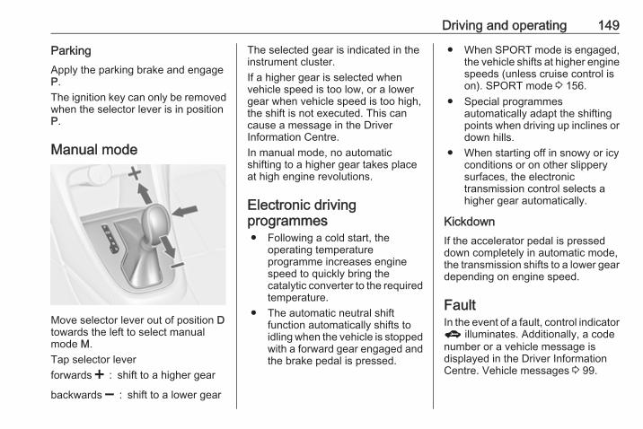
Driving and operating 149
ParkingApply the parking brake and engageP.The ignition key can only be removedwhen the selector lever is in positionP.
Manual mode
Move selector lever out of position Dtowards the left to select manualmode M.Tap selector leverforwards < : shift to a higher gear
backwards ] : shift to a lower gear
The selected gear is indicated in theinstrument cluster.If a higher gear is selected whenvehicle speed is too low, or a lowergear when vehicle speed is too high,the shift is not executed. This cancause a message in the DriverInformation Centre.In manual mode, no automaticshifting to a higher gear takes placeat high engine revolutions.
Electronic drivingprogrammes● Following a cold start, the
operating temperatureprogramme increases enginespeed to quickly bring thecatalytic converter to the requiredtemperature.
● The automatic neutral shiftfunction automatically shifts toidling when the vehicle is stoppedwith a forward gear engaged andthe brake pedal is pressed.
● When SPORT mode is engaged,the vehicle shifts at higher enginespeeds (unless cruise control ison). SPORT mode 3 156.
● Special programmesautomatically adapt the shiftingpoints when driving up inclines ordown hills.
● When starting off in snowy or icyconditions or on other slipperysurfaces, the electronictransmission control selects ahigher gear automatically.
KickdownIf the accelerator pedal is presseddown completely in automatic mode,the transmission shifts to a lower geardepending on engine speed.
FaultIn the event of a fault, control indicatorg illuminates. Additionally, a codenumber or a vehicle message isdisplayed in the Driver InformationCentre. Vehicle messages 3 99.
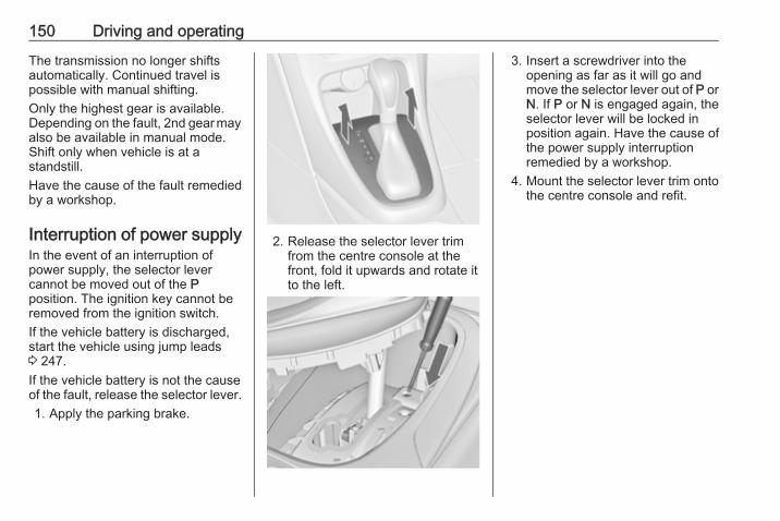
150 Driving and operating
The transmission no longer shiftsautomatically. Continued travel ispossible with manual shifting.Only the highest gear is available.Depending on the fault, 2nd gear mayalso be available in manual mode.Shift only when vehicle is at astandstill.Have the cause of the fault remediedby a workshop.
Interruption of power supplyIn the event of an interruption ofpower supply, the selector levercannot be moved out of the Pposition. The ignition key cannot beremoved from the ignition switch.If the vehicle battery is discharged,start the vehicle using jump leads3 247.If the vehicle battery is not the causeof the fault, release the selector lever.1. Apply the parking brake.
2. Release the selector lever trimfrom the centre console at thefront, fold it upwards and rotate itto the left.
3. Insert a screwdriver into theopening as far as it will go andmove the selector lever out of P orN. If P or N is engaged again, theselector lever will be locked inposition again. Have the cause ofthe power supply interruptionremedied by a workshop.
4. Mount the selector lever trim ontothe centre console and refit.

Driving and operating 151
Manual transmission
To engage reverse, with the vehiclestationary, depress clutch pedal,press the release button on theselector lever and engage the gear.If the gear does not engage, set thelever to neutral, release the clutchpedal and depress again; then repeatgear selection.Do not slip the clutch unnecessarily.When operating, depress the clutchpedal completely. Do not use thepedal as a foot rest.
Caution
It is not advisable to drive with thehand resting on the selector lever.
Upshift indication 3 89.
BrakesThe brake system comprises twoindependent brake circuits.If a brake circuit fails, the vehicle canstill be braked using the other brakecircuit. However, braking effect isachieved only when the brake pedalis depressed firmly. Considerablymore force is needed for this. Thebraking distance is extended. Seekthe assistance of a workshop beforecontinuing your journey.When the engine is not running, thesupport of the brake servo unitdisappears once the brake pedal hasbeen depressed once or twice.Braking effect is not reduced, butbraking requires significantly greaterforce. It is especially important to bearthis in mind when being towed.Control indicator R 3 88.
Antilock brake systemAntilock brake system (ABS)prevents the wheels from locking.
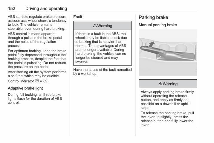
152 Driving and operating
ABS starts to regulate brake pressureas soon as a wheel shows a tendencyto lock. The vehicle remainssteerable, even during hard braking.ABS control is made apparentthrough a pulse in the brake pedaland the noise of the regulationprocess.For optimum braking, keep the brakepedal fully depressed throughout thebraking process, despite the fact thatthe pedal is pulsating. Do not reducethe pressure on the pedal.After starting off the system performsa self-test which may be audible.Control indicator u 3 89.
Adaptive brake lightDuring full braking, all three brakelights flash for the duration of ABScontrol.
Fault
9 Warning
If there is a fault in the ABS, thewheels may be liable to lock dueto braking that is heavier thannormal. The advantages of ABSare no longer available. Duringhard braking, the vehicle can nolonger be steered and mayswerve.
Have the cause of the fault remediedby a workshop.
Parking brakeManual parking brake
9 Warning
Always apply parking brake firmlywithout operating the releasebutton, and apply as firmly aspossible on a downhill or uphillslope.To release the parking brake, pullthe lever up slightly, press therelease button and fully lower thelever.
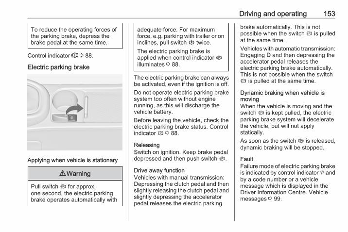
Driving and operating 153
To reduce the operating forces ofthe parking brake, depress thebrake pedal at the same time.
Control indicator R 3 88.
Electric parking brake
Applying when vehicle is stationary
9 Warning
Pull switch m for approx.one second, the electric parkingbrake operates automatically with
adequate force. For maximumforce, e.g. parking with trailer or oninclines, pull switch m twice.The electric parking brake isapplied when control indicator milluminates 3 88.
The electric parking brake can alwaysbe activated, even if the ignition is off.Do not operate electric parking brakesystem too often without enginerunning, as this will discharge thevehicle battery.Before leaving the vehicle, check theelectric parking brake status. Controlindicator m 3 88.
ReleasingSwitch on ignition. Keep brake pedaldepressed and then push switch m.
Drive away functionVehicles with manual transmission:Depressing the clutch pedal and thenslightly releasing the clutch pedal andslightly depressing the acceleratorpedal releases the electric parking
brake automatically. This is notpossible when the switch m is pulledat the same time.Vehicles with automatic transmission:Engaging D and then depressing theaccelerator pedal releases theelectric parking brake automatically.This is not possible when the switchm is pulled at the same time.
Dynamic braking when vehicle ismovingWhen the vehicle is moving and theswitch m is kept pulled, the electricparking brake system will deceleratethe vehicle, but will not applystatically.As soon as the switch m is released,dynamic braking will be stopped.
FaultFailure mode of electric parking brakeis indicated by control indicator j andby a code number or a vehiclemessage which is displayed in theDriver Information Centre. Vehiclemessages 3 99.
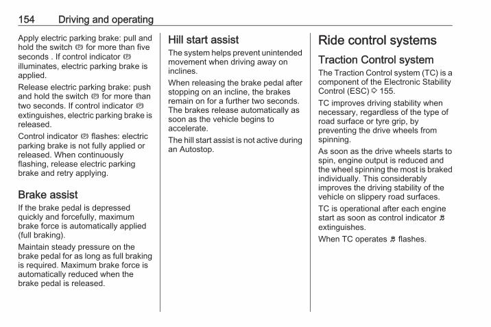
154 Driving and operating
Apply electric parking brake: pull andhold the switch m for more than fiveseconds . If control indicator milluminates, electric parking brake isapplied.Release electric parking brake: pushand hold the switch m for more thantwo seconds. If control indicator mextinguishes, electric parking brake isreleased.Control indicator m flashes: electricparking brake is not fully applied orreleased. When continuouslyflashing, release electric parkingbrake and retry applying.
Brake assistIf the brake pedal is depressedquickly and forcefully, maximumbrake force is automatically applied(full braking).Maintain steady pressure on thebrake pedal for as long as full brakingis required. Maximum brake force isautomatically reduced when thebrake pedal is released.
Hill start assistThe system helps prevent unintendedmovement when driving away oninclines.When releasing the brake pedal afterstopping on an incline, the brakesremain on for a further two seconds.The brakes release automatically assoon as the vehicle begins toaccelerate.The hill start assist is not active duringan Autostop.
Ride control systemsTraction Control systemThe Traction Control system (TC) is acomponent of the Electronic StabilityControl (ESC) 3 155.TC improves driving stability whennecessary, regardless of the type ofroad surface or tyre grip, bypreventing the drive wheels fromspinning.As soon as the drive wheels starts tospin, engine output is reduced andthe wheel spinning the most is brakedindividually. This considerablyimproves the driving stability of thevehicle on slippery road surfaces.TC is operational after each enginestart as soon as control indicator bextinguishes.When TC operates b flashes.
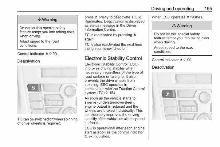
Driving and operating 155
9 Warning
Do not let this special safetyfeature tempt you into taking riskswhen driving.Adapt speed to the roadconditions.
Control indicator b 3 90.
Deactivation
TC can be switched off when spinningof drive wheels is required:
press b briefly to deactivate TC, killuminates. Deactivation is displayedas status message in the DriverInformation Centre.TC is reactivated by pressing bagain.TC is also reactivated the next timethe ignition is switched on.
Electronic Stability ControlElectronic Stability Control (ESC)improves driving stability whennecessary, regardless of the type ofroad surface or tyre grip. It alsoprevents the drive wheels fromspinning. ESC operates incombination with the Traction Controlsystem (TC) 3 154.As soon as the vehicle starts toswerve (understeer/oversteer),engine output is reduced and thewheels are braked individually. Thisconsiderably improves the drivingstability of the vehicle on slippery roadsurfaces.ESC is operational after each enginestart as soon as the control indicatorb extinguishes.
When ESC operates b flashes.
9 Warning
Do not let this special safetyfeature tempt you into taking riskswhen driving.Adapt speed to the roadconditions.
Control indicator b 3 90.
Deactivation
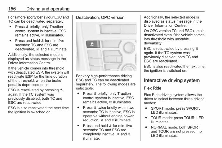
156 Driving and operating
For a more sporty behaviour ESC andTC can be deactivated separately:● Press b briefly: only Traction
control system is inactive, ESCremains active, k illuminates.
● Press and hold b for min. fiveseconds: TC and ESC aredeactivated, k and n illuminate.
Additionally, the selected mode isdisplayed as status message in theDriver Information Centre.If the vehicle comes into thresholdwith deactivated ESP, the system willreactivate ESP for the time durationof the threshold, when the brakepedal is depressed once.ESC is reactivated by pressing bagain. If the TC system waspreviously disabled, both TC andESC are reactivated.ESC is also reactivated the next timethe ignition is switched on.
Deactivation, OPC version
For very high-performance drivingESC and TC can be deactivatedseparately. The following modes areselectable:● Press b briefly: only Traction
control system is inactive, ESCremains active, k illuminates.
● Press b twice briefly within twoseconds: TC is inactive, ESC isoperable without engine powerreduction, k and n illuminate.
● Press and hold b for min. fiveseconds: TC and ESC arecompletely inactive, k and nilluminate.
Additionally, the selected mode isdisplayed as status message in theDriver Information Centre.On OPC version TC and ESC remaindeactivated even if the vehicle comesinto threshold with unstabledriveability.ESC is reactivated by pressing bagain. If the TC system waspreviously disabled, both TC andESC are reactivated.ESC is also reactivated the next timethe ignition is switched on.
Interactive driving systemFlex RideFlex Ride driving system allows thedriver to select between three drivingmodes:● SPORT mode: press SPORT,
LED illuminates.● TOUR mode: press TOUR, LED
illuminates.● NORMAL mode: both SPORT
and TOUR are not pressed, noLED illuminates.
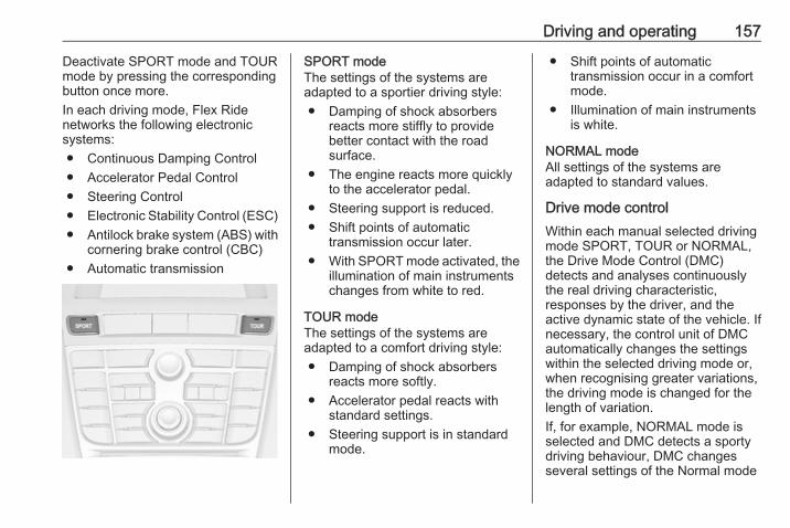
Driving and operating 157
Deactivate SPORT mode and TOURmode by pressing the correspondingbutton once more.In each driving mode, Flex Ridenetworks the following electronicsystems:● Continuous Damping Control● Accelerator Pedal Control● Steering Control● Electronic Stability Control (ESC)● Antilock brake system (ABS) with
cornering brake control (CBC)● Automatic transmission
SPORT modeThe settings of the systems areadapted to a sportier driving style:● Damping of shock absorbers
reacts more stiffly to providebetter contact with the roadsurface.
● The engine reacts more quicklyto the accelerator pedal.
● Steering support is reduced.● Shift points of automatic
transmission occur later.● With SPORT mode activated, the
illumination of main instrumentschanges from white to red.
TOUR modeThe settings of the systems areadapted to a comfort driving style:● Damping of shock absorbers
reacts more softly.● Accelerator pedal reacts with
standard settings.● Steering support is in standard
mode.
● Shift points of automatictransmission occur in a comfortmode.
● Illumination of main instrumentsis white.
NORMAL modeAll settings of the systems areadapted to standard values.
Drive mode controlWithin each manual selected drivingmode SPORT, TOUR or NORMAL,the Drive Mode Control (DMC)detects and analyses continuouslythe real driving characteristic,responses by the driver, and theactive dynamic state of the vehicle. Ifnecessary, the control unit of DMCautomatically changes the settingswithin the selected driving mode or,when recognising greater variations,the driving mode is changed for thelength of variation.If, for example, NORMAL mode isselected and DMC detects a sportydriving behaviour, DMC changesseveral settings of the Normal mode
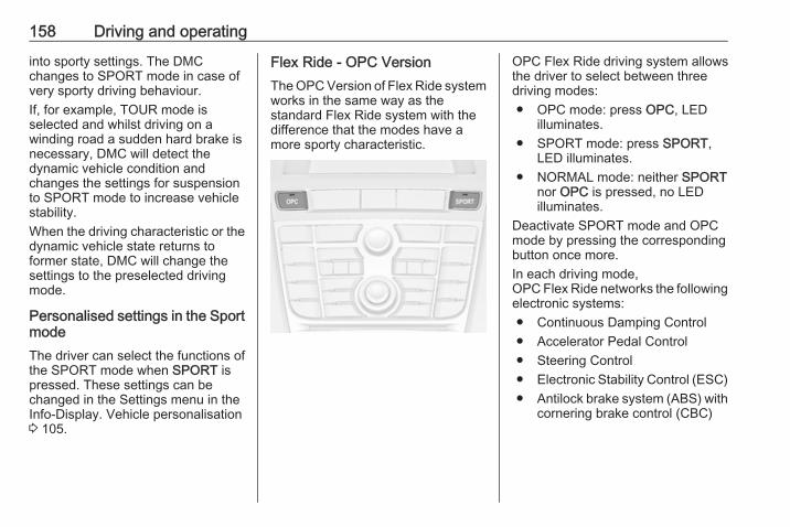
158 Driving and operating
into sporty settings. The DMCchanges to SPORT mode in case ofvery sporty driving behaviour.If, for example, TOUR mode isselected and whilst driving on awinding road a sudden hard brake isnecessary, DMC will detect thedynamic vehicle condition andchanges the settings for suspensionto SPORT mode to increase vehiclestability.When the driving characteristic or thedynamic vehicle state returns toformer state, DMC will change thesettings to the preselected drivingmode.
Personalised settings in the SportmodeThe driver can select the functions ofthe SPORT mode when SPORT ispressed. These settings can bechanged in the Settings menu in theInfo-Display. Vehicle personalisation3 105.
Flex Ride - OPC VersionThe OPC Version of Flex Ride systemworks in the same way as thestandard Flex Ride system with thedifference that the modes have amore sporty characteristic.
OPC Flex Ride driving system allowsthe driver to select between threedriving modes:● OPC mode: press OPC, LED
illuminates.● SPORT mode: press SPORT,
LED illuminates.● NORMAL mode: neither SPORT
nor OPC is pressed, no LEDilluminates.
Deactivate SPORT mode and OPCmode by pressing the correspondingbutton once more.In each driving mode,OPC Flex Ride networks the followingelectronic systems:● Continuous Damping Control● Accelerator Pedal Control● Steering Control● Electronic Stability Control (ESC)● Antilock brake system (ABS) with
cornering brake control (CBC)
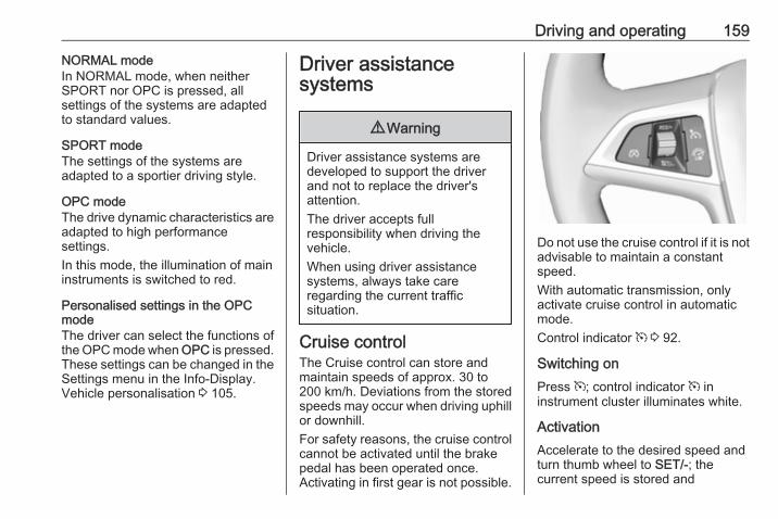
Driving and operating 159
NORMAL modeIn NORMAL mode, when neitherSPORT nor OPC is pressed, allsettings of the systems are adaptedto standard values.
SPORT modeThe settings of the systems areadapted to a sportier driving style.
OPC modeThe drive dynamic characteristics areadapted to high performancesettings.In this mode, the illumination of maininstruments is switched to red.
Personalised settings in the OPCmodeThe driver can select the functions ofthe OPC mode when OPC is pressed.These settings can be changed in theSettings menu in the Info-Display.Vehicle personalisation 3 105.
Driver assistancesystems
9 Warning
Driver assistance systems aredeveloped to support the driverand not to replace the driver'sattention.The driver accepts fullresponsibility when driving thevehicle.When using driver assistancesystems, always take careregarding the current trafficsituation.
Cruise controlThe Cruise control can store andmaintain speeds of approx. 30 to200 km/h. Deviations from the storedspeeds may occur when driving uphillor downhill.For safety reasons, the cruise controlcannot be activated until the brakepedal has been operated once.Activating in first gear is not possible.
Do not use the cruise control if it is notadvisable to maintain a constantspeed.With automatic transmission, onlyactivate cruise control in automaticmode.Control indicator m 3 92.
Switching onPress m; control indicator m ininstrument cluster illuminates white.
ActivationAccelerate to the desired speed andturn thumb wheel to SET/-; thecurrent speed is stored and
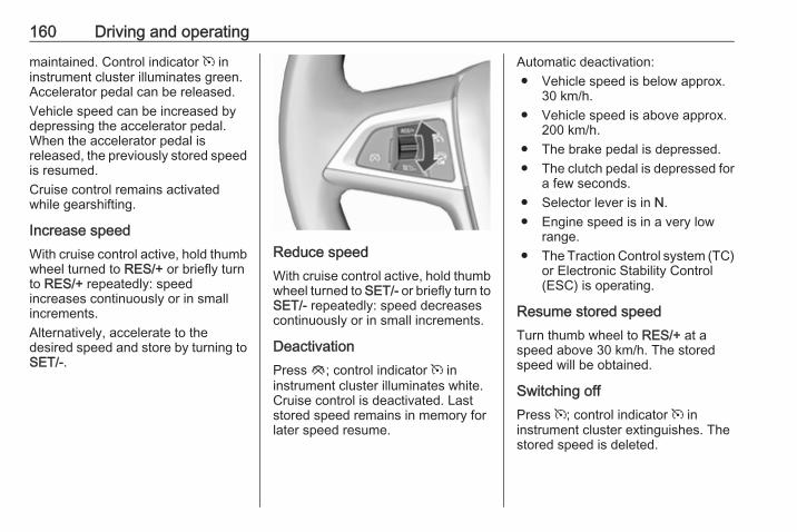
160 Driving and operating
maintained. Control indicator m ininstrument cluster illuminates green.Accelerator pedal can be released.Vehicle speed can be increased bydepressing the accelerator pedal.When the accelerator pedal isreleased, the previously stored speedis resumed.Cruise control remains activatedwhile gearshifting.
Increase speedWith cruise control active, hold thumbwheel turned to RES/+ or briefly turnto RES/+ repeatedly: speedincreases continuously or in smallincrements.Alternatively, accelerate to thedesired speed and store by turning toSET/-.
Reduce speedWith cruise control active, hold thumbwheel turned to SET/- or briefly turn toSET/- repeatedly: speed decreasescontinuously or in small increments.
DeactivationPress y; control indicator m ininstrument cluster illuminates white.Cruise control is deactivated. Laststored speed remains in memory forlater speed resume.
Automatic deactivation:● Vehicle speed is below approx.
30 km/h.● Vehicle speed is above approx.
200 km/h.● The brake pedal is depressed.● The clutch pedal is depressed for
a few seconds.● Selector lever is in N.● Engine speed is in a very low
range.● The Traction Control system (TC)
or Electronic Stability Control(ESC) is operating.
Resume stored speedTurn thumb wheel to RES/+ at aspeed above 30 km/h. The storedspeed will be obtained.
Switching offPress m; control indicator m ininstrument cluster extinguishes. Thestored speed is deleted.
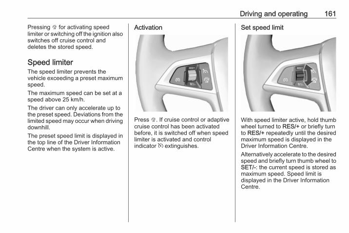
Driving and operating 161
Pressing L for activating speedlimiter or switching off the ignition alsoswitches off cruise control anddeletes the stored speed.
Speed limiterThe speed limiter prevents thevehicle exceeding a preset maximumspeed.The maximum speed can be set at aspeed above 25 km/h.The driver can only accelerate up tothe preset speed. Deviations from thelimited speed may occur when drivingdownhill.The preset speed limit is displayed inthe top line of the Driver InformationCentre when the system is active.
Activation
Press L. If cruise control or adaptivecruise control has been activatedbefore, it is switched off when speedlimiter is activated and controlindicator m extinguishes.
Set speed limit
With speed limiter active, hold thumbwheel turned to RES/+ or briefly turnto RES/+ repeatedly until the desiredmaximum speed is displayed in theDriver Information Centre.Alternatively accelerate to the desiredspeed and briefly turn thumb wheel toSET/-: the current speed is stored asmaximum speed. Speed limit isdisplayed in the Driver InformationCentre.
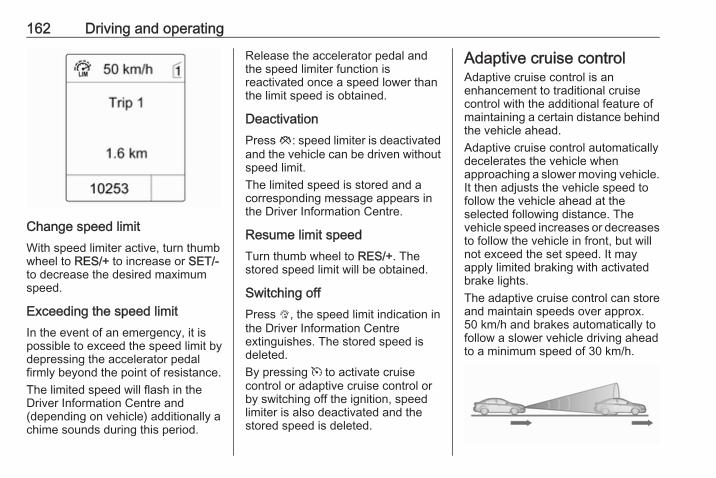
162 Driving and operating
Change speed limitWith speed limiter active, turn thumbwheel to RES/+ to increase or SET/-to decrease the desired maximumspeed.
Exceeding the speed limitIn the event of an emergency, it ispossible to exceed the speed limit bydepressing the accelerator pedalfirmly beyond the point of resistance.The limited speed will flash in theDriver Information Centre and(depending on vehicle) additionally achime sounds during this period.
Release the accelerator pedal andthe speed limiter function isreactivated once a speed lower thanthe limit speed is obtained.
DeactivationPress y: speed limiter is deactivatedand the vehicle can be driven withoutspeed limit.The limited speed is stored and acorresponding message appears inthe Driver Information Centre.
Resume limit speedTurn thumb wheel to RES/+. Thestored speed limit will be obtained.
Switching offPress L, the speed limit indication inthe Driver Information Centreextinguishes. The stored speed isdeleted.By pressing m to activate cruisecontrol or adaptive cruise control orby switching off the ignition, speedlimiter is also deactivated and thestored speed is deleted.
Adaptive cruise controlAdaptive cruise control is anenhancement to traditional cruisecontrol with the additional feature ofmaintaining a certain distance behindthe vehicle ahead.Adaptive cruise control automaticallydecelerates the vehicle whenapproaching a slower moving vehicle.It then adjusts the vehicle speed tofollow the vehicle ahead at theselected following distance. Thevehicle speed increases or decreasesto follow the vehicle in front, but willnot exceed the set speed. It mayapply limited braking with activatedbrake lights.The adaptive cruise control can storeand maintain speeds over approx.50 km/h and brakes automatically tofollow a slower vehicle driving aheadto a minimum speed of 30 km/h.
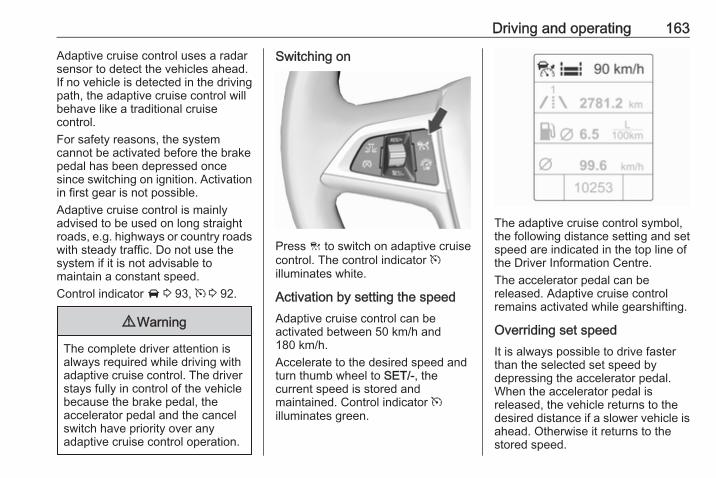
Driving and operating 163
Adaptive cruise control uses a radarsensor to detect the vehicles ahead.If no vehicle is detected in the drivingpath, the adaptive cruise control willbehave like a traditional cruisecontrol.For safety reasons, the systemcannot be activated before the brakepedal has been depressed oncesince switching on ignition. Activationin first gear is not possible.Adaptive cruise control is mainlyadvised to be used on long straightroads, e.g. highways or country roadswith steady traffic. Do not use thesystem if it is not advisable tomaintain a constant speed.Control indicator A 3 93, m 3 92.
9 Warning
The complete driver attention isalways required while driving withadaptive cruise control. The driverstays fully in control of the vehiclebecause the brake pedal, theaccelerator pedal and the cancelswitch have priority over anyadaptive cruise control operation.
Switching on
Press C to switch on adaptive cruisecontrol. The control indicator milluminates white.
Activation by setting the speedAdaptive cruise control can beactivated between 50 km/h and180 km/h.Accelerate to the desired speed andturn thumb wheel to SET/-, thecurrent speed is stored andmaintained. Control indicator milluminates green.
The adaptive cruise control symbol,the following distance setting and setspeed are indicated in the top line ofthe Driver Information Centre.The accelerator pedal can bereleased. Adaptive cruise controlremains activated while gearshifting.
Overriding set speedIt is always possible to drive fasterthan the selected set speed bydepressing the accelerator pedal.When the accelerator pedal isreleased, the vehicle returns to thedesired distance if a slower vehicle isahead. Otherwise it returns to thestored speed.
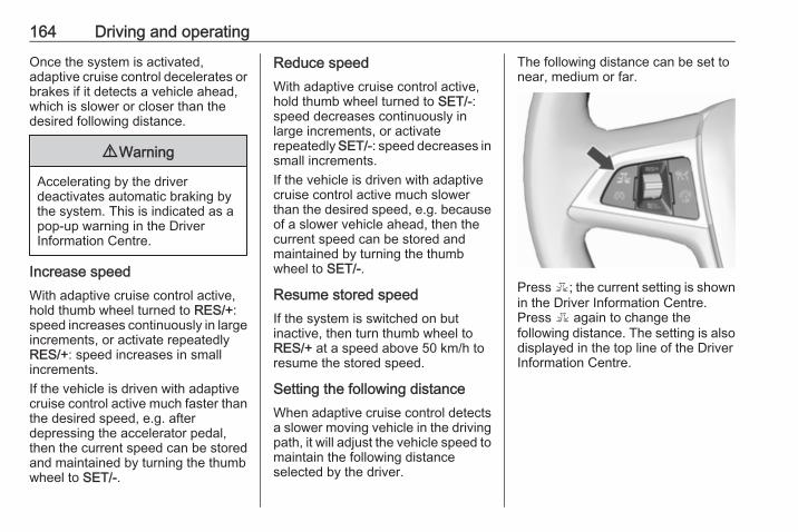
164 Driving and operating
Once the system is activated,adaptive cruise control decelerates orbrakes if it detects a vehicle ahead,which is slower or closer than thedesired following distance.
9 Warning
Accelerating by the driverdeactivates automatic braking bythe system. This is indicated as apop-up warning in the DriverInformation Centre.
Increase speedWith adaptive cruise control active,hold thumb wheel turned to RES/+:speed increases continuously in largeincrements, or activate repeatedlyRES/+: speed increases in smallincrements.If the vehicle is driven with adaptivecruise control active much faster thanthe desired speed, e.g. afterdepressing the accelerator pedal,then the current speed can be storedand maintained by turning the thumbwheel to SET/-.
Reduce speedWith adaptive cruise control active,hold thumb wheel turned to SET/-:speed decreases continuously inlarge increments, or activaterepeatedly SET/-: speed decreases insmall increments.If the vehicle is driven with adaptivecruise control active much slowerthan the desired speed, e.g. becauseof a slower vehicle ahead, then thecurrent speed can be stored andmaintained by turning the thumbwheel to SET/-.
Resume stored speedIf the system is switched on butinactive, then turn thumb wheel toRES/+ at a speed above 50 km/h toresume the stored speed.
Setting the following distanceWhen adaptive cruise control detectsa slower moving vehicle in the drivingpath, it will adjust the vehicle speed tomaintain the following distanceselected by the driver.
The following distance can be set tonear, medium or far.
Press E; the current setting is shownin the Driver Information Centre.Press E again to change thefollowing distance. The setting is alsodisplayed in the top line of the DriverInformation Centre.
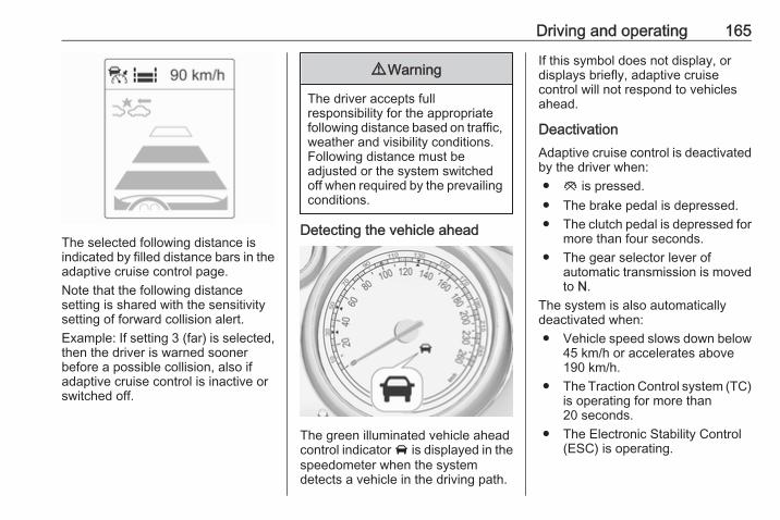
Driving and operating 165
The selected following distance isindicated by filled distance bars in theadaptive cruise control page.Note that the following distancesetting is shared with the sensitivitysetting of forward collision alert.Example: If setting 3 (far) is selected,then the driver is warned soonerbefore a possible collision, also ifadaptive cruise control is inactive orswitched off.
9 Warning
The driver accepts fullresponsibility for the appropriatefollowing distance based on traffic,weather and visibility conditions.Following distance must beadjusted or the system switchedoff when required by the prevailingconditions.
Detecting the vehicle ahead
The green illuminated vehicle aheadcontrol indicator A is displayed in thespeedometer when the systemdetects a vehicle in the driving path.
If this symbol does not display, ordisplays briefly, adaptive cruisecontrol will not respond to vehiclesahead.
DeactivationAdaptive cruise control is deactivatedby the driver when:● y is pressed.● The brake pedal is depressed.● The clutch pedal is depressed for
more than four seconds.● The gear selector lever of
automatic transmission is movedto N.
The system is also automaticallydeactivated when:● Vehicle speed slows down below
45 km/h or accelerates above190 km/h.
● The Traction Control system (TC)is operating for more than20 seconds.
● The Electronic Stability Control(ESC) is operating.
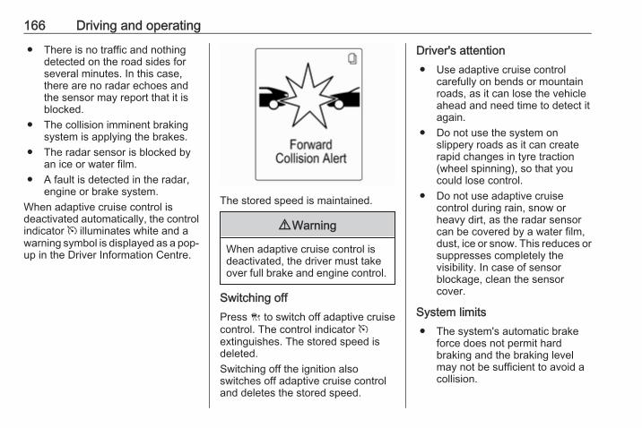
166 Driving and operating
● There is no traffic and nothingdetected on the road sides forseveral minutes. In this case,there are no radar echoes andthe sensor may report that it isblocked.
● The collision imminent brakingsystem is applying the brakes.
● The radar sensor is blocked byan ice or water film.
● A fault is detected in the radar,engine or brake system.
When adaptive cruise control isdeactivated automatically, the controlindicator m illuminates white and awarning symbol is displayed as a pop-up in the Driver Information Centre.
The stored speed is maintained.
9 Warning
When adaptive cruise control isdeactivated, the driver must takeover full brake and engine control.
Switching offPress C to switch off adaptive cruisecontrol. The control indicator mextinguishes. The stored speed isdeleted.Switching off the ignition alsoswitches off adaptive cruise controland deletes the stored speed.
Driver's attention● Use adaptive cruise control
carefully on bends or mountainroads, as it can lose the vehicleahead and need time to detect itagain.
● Do not use the system onslippery roads as it can createrapid changes in tyre traction(wheel spinning), so that youcould lose control.
● Do not use adaptive cruisecontrol during rain, snow orheavy dirt, as the radar sensorcan be covered by a water film,dust, ice or snow. This reduces orsuppresses completely thevisibility. In case of sensorblockage, clean the sensorcover.
System limits● The system's automatic brake
force does not permit hardbraking and the braking levelmay not be sufficient to avoid acollision.
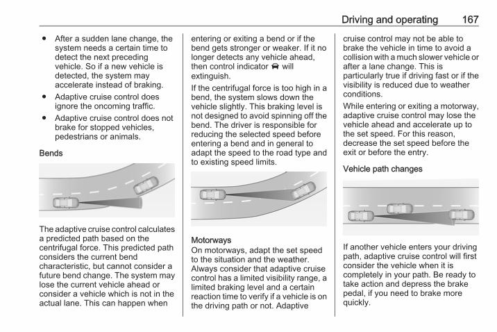
Driving and operating 167
● After a sudden lane change, thesystem needs a certain time todetect the next precedingvehicle. So if a new vehicle isdetected, the system mayaccelerate instead of braking.
● Adaptive cruise control doesignore the oncoming traffic.
● Adaptive cruise control does notbrake for stopped vehicles,pedestrians or animals.
Bends
The adaptive cruise control calculatesa predicted path based on thecentrifugal force. This predicted pathconsiders the current bendcharacteristic, but cannot consider afuture bend change. The system maylose the current vehicle ahead orconsider a vehicle which is not in theactual lane. This can happen when
entering or exiting a bend or if thebend gets stronger or weaker. If it nolonger detects any vehicle ahead,then control indicator A willextinguish.If the centrifugal force is too high in abend, the system slows down thevehicle slightly. This braking level isnot designed to avoid spinning off thebend. The driver is responsible forreducing the selected speed beforeentering a bend and in general toadapt the speed to the road type andto existing speed limits.
MotorwaysOn motorways, adapt the set speedto the situation and the weather.Always consider that adaptive cruisecontrol has a limited visibility range, alimited braking level and a certainreaction time to verify if a vehicle is onthe driving path or not. Adaptive
cruise control may not be able tobrake the vehicle in time to avoid acollision with a much slower vehicle orafter a lane change. This isparticularly true if driving fast or if thevisibility is reduced due to weatherconditions.While entering or exiting a motorway,adaptive cruise control may lose thevehicle ahead and accelerate up tothe set speed. For this reason,decrease the set speed before theexit or before the entry.
Vehicle path changes
If another vehicle enters your drivingpath, adaptive cruise control will firstconsider the vehicle when it iscompletely in your path. Be ready totake action and depress the brakepedal, if you need to brake morequickly.
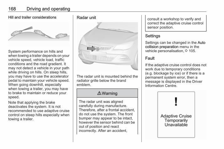
168 Driving and operating
Hill and trailer considerations
System performance on hills andwhen towing a trailer depends on yourvehicle speed, vehicle load, trafficconditions and the road gradient. Itmay not detect a vehicle in your pathwhile driving on hills. On steep hills,you may have to use the acceleratorpedal to maintain your vehicle speed.When going downhill, especiallywhen towing a trailer, you may haveto brake to maintain or reduce yourspeed.Note that applying the brakedeactivates the system. It is notrecommended to use adaptive cruisecontrol on steep hills especially whentowing a trailer.
Radar unit
The radar unit is mounted behind theradiator grille below the brandemblem.
9 Warning
The radar unit was alignedcarefully during manufacture.Therefore, after a frontal accident,do not use the system. The frontbumper may appear to be intact,however the sensor behind can beout of position and reactincorrectly. After an accident,
consult a workshop to verify andcorrect the adaptive cruise controlsensor position.
SettingsSettings can be changed in the Autocollision preparation menu in thevehicle personalisation, 3 105.
FaultIf the adaptive cruise control does notwork due to temporary conditions(e.g. blockage by ice) or if there is apermanent system error, then amessage is displayed in the DriverInformation Centre.
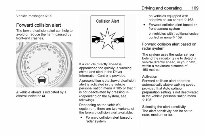
Driving and operating 169
Vehicle messages 3 99.
Forward collision alertThe forward collision alert can help toavoid or reduce the harm caused byfront-end crashes.
A vehicle ahead is indicated by acontrol indicator A.
If a vehicle directly ahead isapproached too quickly, a warningchime and alert in the DriverInformation Centre is provided.A precondition is that forward collisionalert is activated in the vehiclepersonalisation menu 3 105 or that itis not deactivated by pressing V(depending on the system, seefollowing).Depending on the vehicle'sequipment, there are two variants ofthe forward collision alert available:● Forward collision alert based on
radar system
on vehicles equipped withadaptive cruise control 3 162.
● Forward collision alert based onfront camera systemon vehicles with traditional cruisecontrol or none 3 159.
Forward collision alert based onradar systemThe system uses the radar sensorbehind the radiator grille to detect avehicle directly ahead, in your path,within a maximum distance of150 metres.
ActivationForward collision alert operatesautomatically above walking speed,provided that Auto collisionpreparation setting is not deactivatedin the vehicle personalisation menu3 105.
Selecting the alert sensitivityThe alert sensitivity can be set tonear, medium or far.
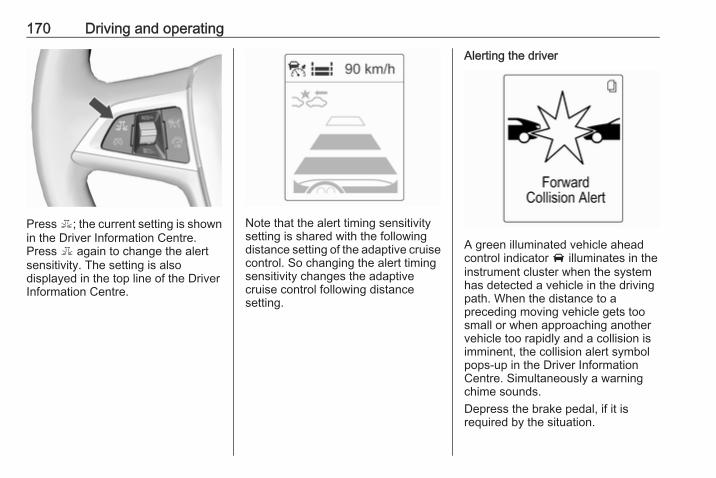
170 Driving and operating
Press E; the current setting is shownin the Driver Information Centre.Press E again to change the alertsensitivity. The setting is alsodisplayed in the top line of the DriverInformation Centre.
Note that the alert timing sensitivitysetting is shared with the followingdistance setting of the adaptive cruisecontrol. So changing the alert timingsensitivity changes the adaptivecruise control following distancesetting.
Alerting the driver
A green illuminated vehicle aheadcontrol indicator A illuminates in theinstrument cluster when the systemhas detected a vehicle in the drivingpath. When the distance to apreceding moving vehicle gets toosmall or when approaching anothervehicle too rapidly and a collision isimminent, the collision alert symbolpops-up in the Driver InformationCentre. Simultaneously a warningchime sounds.Depress the brake pedal, if it isrequired by the situation.
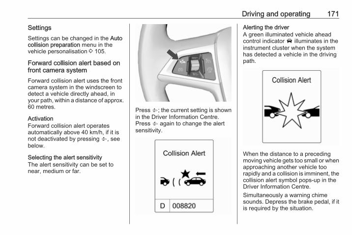
Driving and operating 171
SettingsSettings can be changed in the Autocollision preparation menu in thevehicle personalisation 3 105.
Forward collision alert based onfront camera systemForward collision alert uses the frontcamera system in the windscreen todetect a vehicle directly ahead, inyour path, within a distance of approx.60 metres.
ActivationForward collision alert operatesautomatically above 40 km/h, if it isnot deactivated by pressing V, seebelow.
Selecting the alert sensitivityThe alert sensitivity can be set tonear, medium or far.
Press V; the current setting is shownin the Driver Information Centre.Press V again to change the alertsensitivity.
Alerting the driverA green illuminated vehicle aheadcontrol indicator A illuminates in theinstrument cluster when the systemhas detected a vehicle in the drivingpath.
When the distance to a precedingmoving vehicle gets too small or whenapproaching another vehicle toorapidly and a collision is imminent, thecollision alert symbol pops-up in theDriver Information Centre.Simultaneously a warning chimesounds. Depress the brake pedal, if itis required by the situation.
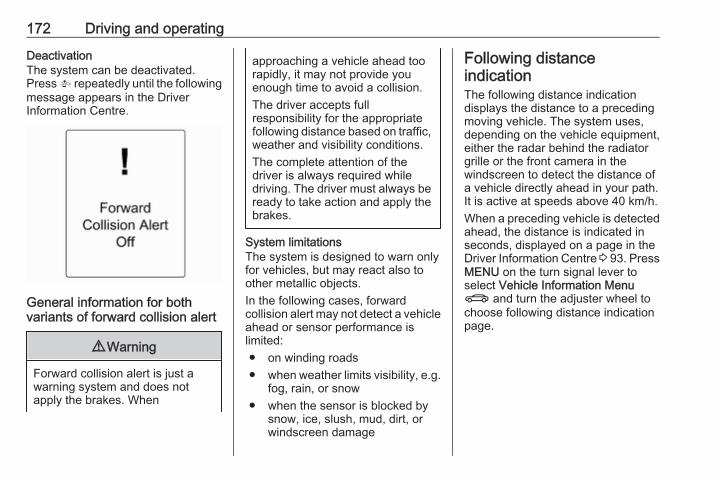
172 Driving and operating
DeactivationThe system can be deactivated.Press V repeatedly until the followingmessage appears in the DriverInformation Centre.
General information for bothvariants of forward collision alert
9 Warning
Forward collision alert is just awarning system and does notapply the brakes. When
approaching a vehicle ahead toorapidly, it may not provide youenough time to avoid a collision.The driver accepts fullresponsibility for the appropriatefollowing distance based on traffic,weather and visibility conditions.The complete attention of thedriver is always required whiledriving. The driver must always beready to take action and apply thebrakes.
System limitationsThe system is designed to warn onlyfor vehicles, but may react also toother metallic objects.In the following cases, forwardcollision alert may not detect a vehicleahead or sensor performance islimited:● on winding roads● when weather limits visibility, e.g.
fog, rain, or snow● when the sensor is blocked by
snow, ice, slush, mud, dirt, orwindscreen damage
Following distanceindicationThe following distance indicationdisplays the distance to a precedingmoving vehicle. The system uses,depending on the vehicle equipment,either the radar behind the radiatorgrille or the front camera in thewindscreen to detect the distance ofa vehicle directly ahead in your path.It is active at speeds above 40 km/h.When a preceding vehicle is detectedahead, the distance is indicated inseconds, displayed on a page in theDriver Information Centre 3 93. PressMENU on the turn signal lever toselect Vehicle Information MenuX and turn the adjuster wheel tochoose following distance indicationpage.
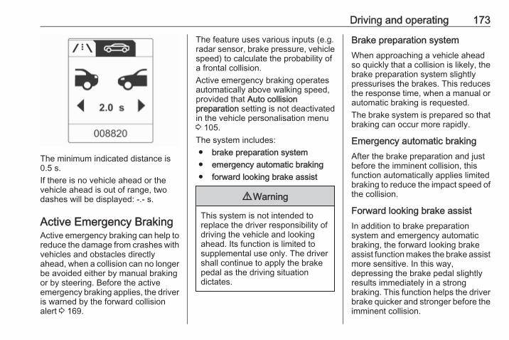
Driving and operating 173
The minimum indicated distance is0.5 s.If there is no vehicle ahead or thevehicle ahead is out of range, twodashes will be displayed: -.- s.
Active Emergency BrakingActive emergency braking can help toreduce the damage from crashes withvehicles and obstacles directlyahead, when a collision can no longerbe avoided either by manual brakingor by steering. Before the activeemergency braking applies, the driveris warned by the forward collisionalert 3 169.
The feature uses various inputs (e.g.radar sensor, brake pressure, vehiclespeed) to calculate the probability ofa frontal collision.Active emergency braking operatesautomatically above walking speed,provided that Auto collisionpreparation setting is not deactivatedin the vehicle personalisation menu3 105.The system includes:● brake preparation system● emergency automatic braking● forward looking brake assist
9 Warning
This system is not intended toreplace the driver responsibility ofdriving the vehicle and lookingahead. Its function is limited tosupplemental use only. The drivershall continue to apply the brakepedal as the driving situationdictates.
Brake preparation systemWhen approaching a vehicle aheadso quickly that a collision is likely, thebrake preparation system slightlypressurises the brakes. This reducesthe response time, when a manual orautomatic braking is requested.The brake system is prepared so thatbraking can occur more rapidly.
Emergency automatic brakingAfter the brake preparation and justbefore the imminent collision, thisfunction automatically applies limitedbraking to reduce the impact speed ofthe collision.
Forward looking brake assistIn addition to brake preparationsystem and emergency automaticbraking, the forward looking brakeassist function makes the brake assistmore sensitive. In this way,depressing the brake pedal slightlyresults immediately in a strongbraking. This function helps the driverbrake quicker and stronger before theimminent collision.
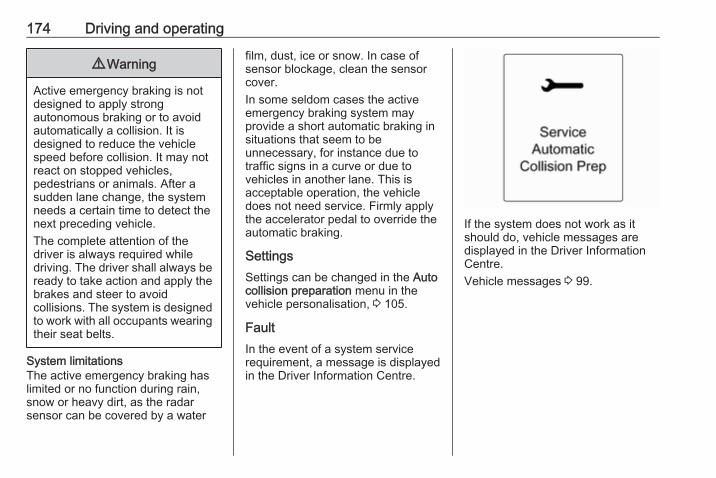
174 Driving and operating
9 Warning
Active emergency braking is notdesigned to apply strongautonomous braking or to avoidautomatically a collision. It isdesigned to reduce the vehiclespeed before collision. It may notreact on stopped vehicles,pedestrians or animals. After asudden lane change, the systemneeds a certain time to detect thenext preceding vehicle.The complete attention of thedriver is always required whiledriving. The driver shall always beready to take action and apply thebrakes and steer to avoidcollisions. The system is designedto work with all occupants wearingtheir seat belts.
System limitationsThe active emergency braking haslimited or no function during rain,snow or heavy dirt, as the radarsensor can be covered by a water
film, dust, ice or snow. In case ofsensor blockage, clean the sensorcover.In some seldom cases the activeemergency braking system mayprovide a short automatic braking insituations that seem to beunnecessary, for instance due totraffic signs in a curve or due tovehicles in another lane. This isacceptable operation, the vehicledoes not need service. Firmly applythe accelerator pedal to override theautomatic braking.
SettingsSettings can be changed in the Autocollision preparation menu in thevehicle personalisation, 3 105.
FaultIn the event of a system servicerequirement, a message is displayedin the Driver Information Centre.
If the system does not work as itshould do, vehicle messages aredisplayed in the Driver InformationCentre.Vehicle messages 3 99.
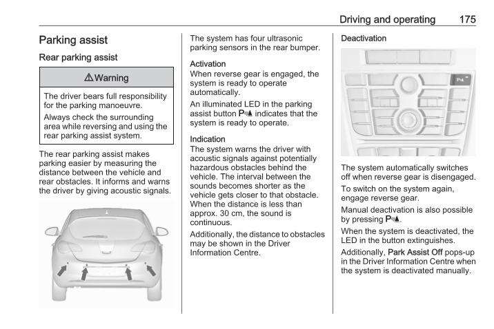
Driving and operating 175
Parking assistRear parking assist
9 Warning
The driver bears full responsibilityfor the parking manoeuvre.Always check the surroundingarea while reversing and using therear parking assist system.
The rear parking assist makesparking easier by measuring thedistance between the vehicle andrear obstacles. It informs and warnsthe driver by giving acoustic signals.
The system has four ultrasonicparking sensors in the rear bumper.
ActivationWhen reverse gear is engaged, thesystem is ready to operateautomatically.An illuminated LED in the parkingassist button r indicates that thesystem is ready to operate.
IndicationThe system warns the driver withacoustic signals against potentiallyhazardous obstacles behind thevehicle. The interval between thesounds becomes shorter as thevehicle gets closer to that obstacle.When the distance is less thanapprox. 30 cm, the sound iscontinuous.Additionally, the distance to obstaclesmay be shown in the DriverInformation Centre.
Deactivation
The system automatically switchesoff when reverse gear is disengaged.To switch on the system again,engage reverse gear.Manual deactivation is also possibleby pressing r.When the system is deactivated, theLED in the button extinguishes.Additionally, Park Assist Off pops-upin the Driver Information Centre whenthe system is deactivated manually.
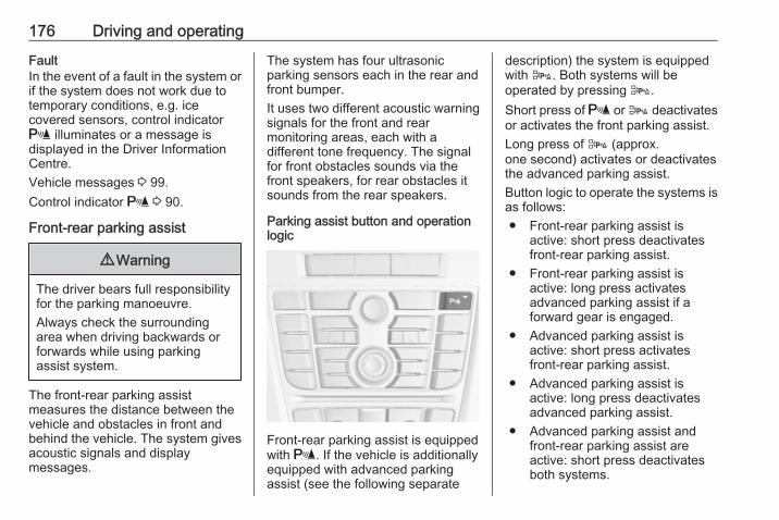
176 Driving and operating
FaultIn the event of a fault in the system orif the system does not work due totemporary conditions, e.g. icecovered sensors, control indicatorr illuminates or a message isdisplayed in the Driver InformationCentre.Vehicle messages 3 99.Control indicator r 3 90.
Front-rear parking assist
9 Warning
The driver bears full responsibilityfor the parking manoeuvre.Always check the surroundingarea when driving backwards orforwards while using parkingassist system.
The front-rear parking assistmeasures the distance between thevehicle and obstacles in front andbehind the vehicle. The system givesacoustic signals and displaymessages.
The system has four ultrasonicparking sensors each in the rear andfront bumper.It uses two different acoustic warningsignals for the front and rearmonitoring areas, each with adifferent tone frequency. The signalfor front obstacles sounds via thefront speakers, for rear obstacles itsounds from the rear speakers.
Parking assist button and operationlogic
Front-rear parking assist is equippedwith r. If the vehicle is additionallyequipped with advanced parkingassist (see the following separate
description) the system is equippedwith D. Both systems will beoperated by pressing D.Short press of r or D deactivatesor activates the front parking assist.Long press of D (approx.one second) activates or deactivatesthe advanced parking assist.Button logic to operate the systems isas follows:● Front-rear parking assist is
active: short press deactivatesfront-rear parking assist.
● Front-rear parking assist isactive: long press activatesadvanced parking assist if aforward gear is engaged.
● Advanced parking assist isactive: short press activatesfront-rear parking assist.
● Advanced parking assist isactive: long press deactivatesadvanced parking assist.
● Advanced parking assist andfront-rear parking assist areactive: short press deactivatesboth systems.
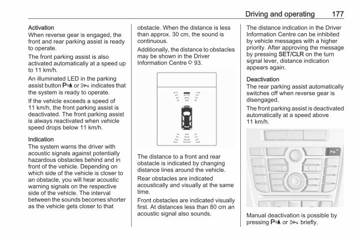
Driving and operating 177
ActivationWhen reverse gear is engaged, thefront and rear parking assist is readyto operate.The front parking assist is alsoactivated automatically at a speed upto 11 km/h.An illuminated LED in the parkingassist button r or D indicates thatthe system is ready to operate.If the vehicle exceeds a speed of11 km/h, the front parking assist isdeactivated. The front parking assistis always reactivated when vehiclespeed drops below 11 km/h.
IndicationThe system warns the driver withacoustic signals against potentiallyhazardous obstacles behind and infront of the vehicle. Depending onwhich side of the vehicle is closer toan obstacle, you will hear acousticwarning signals on the respectiveside of the vehicle. The intervalbetween the sounds becomes shorteras the vehicle gets closer to that
obstacle. When the distance is lessthan approx. 30 cm, the sound iscontinuous.Additionally, the distance to obstaclesmay be shown in the DriverInformation Centre 3 93.
The distance to a front and rearobstacle is indicated by changingdistance lines around the vehicle.Rear obstacles are indicatedacoustically and visually at the sametime.Front obstacles are indicated visuallyfirst. At distances less than 80 cm anacoustic signal also sounds.
The distance indication in the DriverInformation Centre can be inhibitedby vehicle messages with a higherpriority. After approving the messageby pressing SET/CLR on the turnsignal lever, distance indicationappears again.
DeactivationThe rear parking assist automaticallyswitches off when reverse gear isdisengaged.The front parking assist is deactivatedautomatically at a speed above11 km/h.
Manual deactivation is possible bypressing r or D briefly.
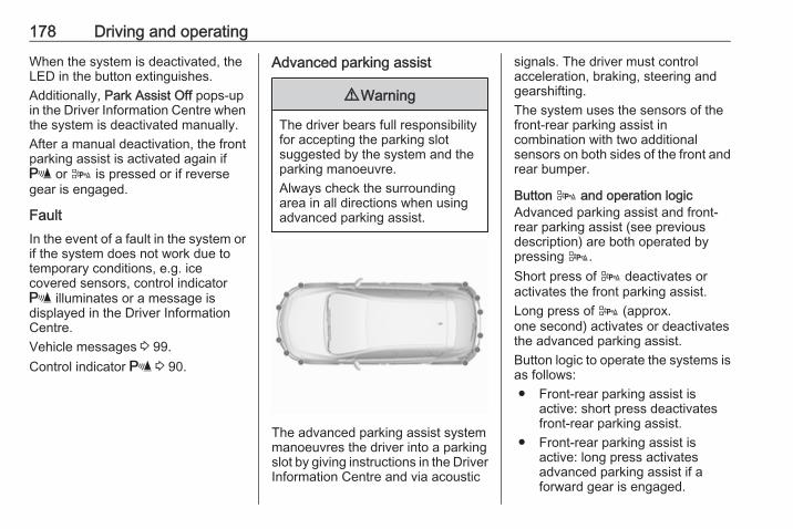
178 Driving and operating
When the system is deactivated, theLED in the button extinguishes.Additionally, Park Assist Off pops-upin the Driver Information Centre whenthe system is deactivated manually.After a manual deactivation, the frontparking assist is activated again ifr or D is pressed or if reversegear is engaged.
FaultIn the event of a fault in the system orif the system does not work due totemporary conditions, e.g. icecovered sensors, control indicatorr illuminates or a message isdisplayed in the Driver InformationCentre.Vehicle messages 3 99.Control indicator r 3 90.
Advanced parking assist
9 Warning
The driver bears full responsibilityfor accepting the parking slotsuggested by the system and theparking manoeuvre.Always check the surroundingarea in all directions when usingadvanced parking assist.
The advanced parking assist systemmanoeuvres the driver into a parkingslot by giving instructions in the DriverInformation Centre and via acoustic
signals. The driver must controlacceleration, braking, steering andgearshifting.The system uses the sensors of thefront-rear parking assist incombination with two additionalsensors on both sides of the front andrear bumper.
Button D and operation logicAdvanced parking assist and front-rear parking assist (see previousdescription) are both operated bypressing D.Short press of D deactivates oractivates the front parking assist.Long press of D (approx.one second) activates or deactivatesthe advanced parking assist.Button logic to operate the systems isas follows:● Front-rear parking assist is
active: short press deactivatesfront-rear parking assist.
● Front-rear parking assist isactive: long press activatesadvanced parking assist if aforward gear is engaged.
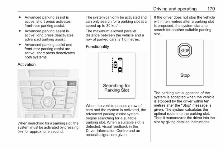
Driving and operating 179
● Advanced parking assist isactive: short press activatesfront-rear parking assist.
● Advanced parking assist isactive: long press deactivatesadvanced parking assist.
● Advanced parking assist andfront-rear parking assist areactive: short press deactivatesboth systems.
Activation
When searching for a parking slot, thesystem must be activated by pressingD for approx. one second.
The system can only be activated andcan only search for a parking slot at aspeed up to 30 km/h.The maximum allowed paralleldistance between the vehicle and arow of parked cars is 1.8 metres.
Functionality
When the vehicle passes a row ofcars and the system is activated, theadvanced parking assist systembegins searching for a suitableparking slot. When a suitable slot isdetected, visual feedback in theDriver Information Centre and anacoustic signal are given.
If the driver does not stop the vehiclewithin ten metres after a parking slotis proposed, the system starts tosearch for another suitable parkingslot.
The parking slot suggestion of thesystem is accepted when the vehicleis stopped by the driver within tenmetres after the "Stop" message isgiven. The system calculates theoptimal route into the parking slot.Then it manoeuvres the driver into theslot by giving detailed instructions.
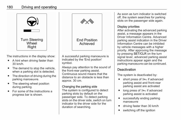
180 Driving and operating
The instructions in the display show:● A hint when driving faster than
30 km/h.● The demand to stop the vehicle,
when a parking slot is detected.● The direction of driving during the
parking manoeuvre.● The steering wheel position
during parking.● For some of the instructions a
progress bar is shown.
A successful parking manoeuvre isindicated by the 'End position'symbol.Always pay attention to the sound ofthe front-rear parking assist.Continuous sound means that thedistance to an obstacle is less thanapprox. 30 cm.
Changing the parking sideThe system is configured to detectparking slots by default on thepassenger side. To detect parkingslots on the driver side, switch on turnindicator to the driver side for theduration of searching.
As soon as turn indicator is switchedoff, the system searches for parkingslots on the passenger side again.
Display prioritiesAfter activating the advanced parkingassist, a message appears in theDriver Information Centre. Advancedparking assist indication in the DriverInformation Centre can be inhibitedby vehicle messages with a higherpriority. After approving the messageby pressing SET/CLR on the turnsignal lever, advanced parking assistinstructions appear again and theparking manoeuvre can be continued.
DeactivationThe system is deactivated by:● short press of D if advanced
parking assist and front-rearparking assist are activated
● long press of D if advancedparking assist is activated
● successfully ending parkingmanoeuvre
● driving faster than 30 km/h● switching off the ignition
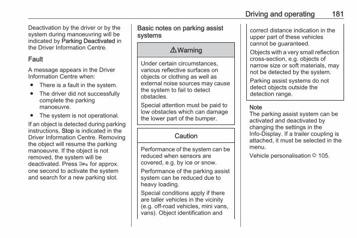
Driving and operating 181
Deactivation by the driver or by thesystem during manoeuvring will beindicated by Parking Deactivated inthe Driver Information Centre.
FaultA message appears in the DriverInformation Centre when:● There is a fault in the system.● The driver did not successfully
complete the parkingmanoeuvre.
● The system is not operational.If an object is detected during parkinginstructions, Stop is indicated in theDriver Information Centre. Removingthe object will resume the parkingmanoeuvre. If the object is notremoved, the system will bedeactivated. Press D for approx.one second to activate the systemand search for a new parking slot.
Basic notes on parking assistsystems
9 Warning
Under certain circumstances,various reflective surfaces onobjects or clothing as well asexternal noise sources may causethe system to fail to detectobstacles.Special attention must be paid tolow obstacles which can damagethe lower part of the bumper.
Caution
Performance of the system can bereduced when sensors arecovered, e.g. by ice or snow.Performance of the parking assistsystem can be reduced due toheavy loading.Special conditions apply if thereare taller vehicles in the vicinity(e.g. off-road vehicles, mini vans,vans). Object identification and
correct distance indication in theupper part of these vehiclescannot be guaranteed.Objects with a very small reflectioncross-section, e.g. objects ofnarrow size or soft materials, maynot be detected by the system.Parking assist systems do notdetect objects outside thedetection range.
NoteThe parking assist system can beactivated and deactivated bychanging the settings in theInfo-Display. If a trailer coupling isattached, it must be selected in themenu.Vehicle personalisation 3 105.
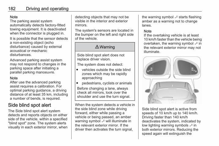
182 Driving and operating
NoteThe parking assist systemautomatically detects factory-fittedtowing equipment. It is deactivatedwhen the connector is plugged in.It is possible that the sensor detectsa non-existing object (echodisturbance) caused by externalacoustical or mechanicdisturbances.Advanced parking assist systemmay not respond to changes in theparking space after initiating aparallel parking manoeuvre.NoteAfter use the advanced parkingassist requires a calibration. Foroptimal parking guidance, a drivingdistance of at least 35 km, includinga number of bends, is required.
Side blind spot alertThe Side blind spot alert systemdetects and reports objects on eitherside of the vehicle, within a specified"blind spot" zone. The system alertsvisually in each exterior mirror, when
detecting objects that may not bevisible in the interior and exteriormirrors.The system's sensors are located inthe bumper on the left and right sideof the vehicle.
9 Warning
Side blind spot alert does notreplace driver vision.The system does not detect:
● vehicles outside the side blindzones which may be rapidlyapproaching
● pedestrians, cyclists or animalsBefore changing a lane, alwayscheck all mirrors, look over theshoulder and use the turn signal.
When the system detects a vehicle inthe side blind zone while drivingforward, either while passing avehicle or being passed, an amberwarning symbol B will illuminate inthe relevant exterior mirror. If thedriver then activates the turn signal,
the warning symbol B starts flashingamber as a warning not to changelanes.NoteIf the overtaking vehicle is at least10 km/h faster than the vehicle beingovertaken, the warning symbol B inthe relevant exterior mirror may notilluminate.
Side blind spot alert is active fromspeeds of 10 km/h up to 140 km/h.Driving faster than 140 km/hdeactivates the system, indicated bylow lighting warning symbols B inboth exterior mirrors. Reducing thespeed again will extinguish the
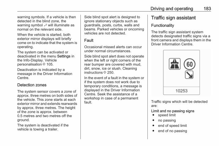
Driving and operating 183
warning symbols. If a vehicle is thendetected in the blind zone, thewarning symbol B will illuminate asnormal on the relevant side.When the vehicle is started, bothexterior mirror displays will brieflycome on to indicate that the system isoperating.The system can be activated ordeactivated in the menu Settings inthe Info-Display. Vehiclepersonalisation 3 105.Deactivation is indicated by amessage in the Driver InformationCentre.
Detection zonesThe system sensor covers a zone ofapprox. three metres on both sides ofthe vehicle. This zone starts at eachexterior mirror and extends rearwardsby approx. three metres. The heightof the zone is approx. between0.5 metres and two metres off theground.The system is deactivated if thevehicle is towing a trailer.
Side blind spot alert is designed toignore stationary objects such asguardrails, posts, curbs, walls andbeams. Parked vehicles or oncomingvehicles are not detected.
FaultOccasional missed alerts can occurunder normal circumstances.Side blind spot alert does not operatewhen the left or right corners of therear bumper are covered with mud,dirt, snow, ice or slush. Cleaninginstructions 3 250.In the event of a fault in the system orif the system does not work due totemporary conditions, a message isdisplayed in the Driver InformationCentre. Seek the assistance of aworkshop in case of a permanentfault.
Traffic sign assistantFunctionalityThe traffic sign assistant systemdetects designated traffic signs via afront camera and displays them in theDriver Information Centre.
Traffic signs which will be detectedare:Limit and no passing signs● speed limit● no passing● end of speed limit● end of no passing
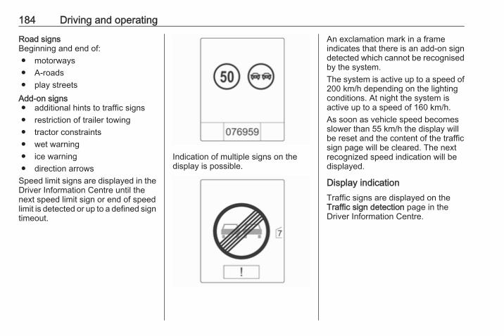
184 Driving and operating
Road signsBeginning and end of:● motorways● A-roads● play streets
Add-on signs● additional hints to traffic signs● restriction of trailer towing● tractor constraints● wet warning● ice warning● direction arrows
Speed limit signs are displayed in theDriver Information Centre until thenext speed limit sign or end of speedlimit is detected or up to a defined signtimeout.
Indication of multiple signs on thedisplay is possible.
An exclamation mark in a frameindicates that there is an add-on signdetected which cannot be recognisedby the system.The system is active up to a speed of200 km/h depending on the lightingconditions. At night the system isactive up to a speed of 160 km/h.As soon as vehicle speed becomesslower than 55 km/h the display willbe reset and the content of the trafficsign page will be cleared. The nextrecognized speed indication will bedisplayed.
Display indicationTraffic signs are displayed on theTraffic sign detection page in theDriver Information Centre.
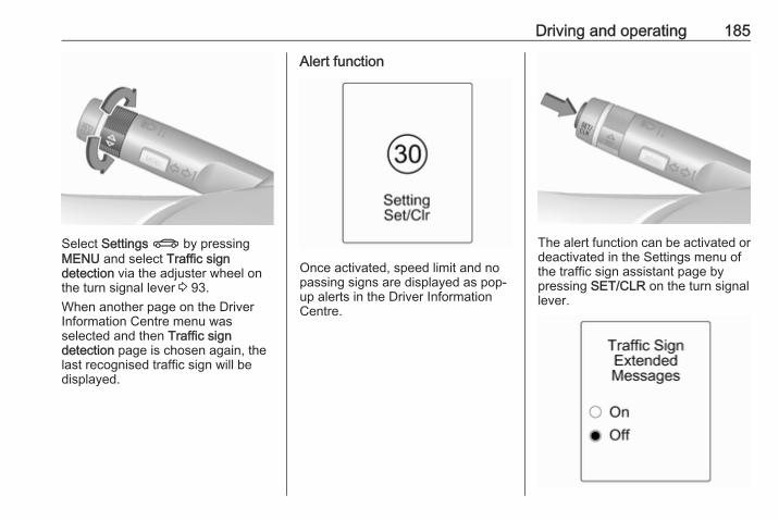
Driving and operating 185
Select Settings X by pressingMENU and select Traffic signdetection via the adjuster wheel onthe turn signal lever 3 93.When another page on the DriverInformation Centre menu wasselected and then Traffic signdetection page is chosen again, thelast recognised traffic sign will bedisplayed.
Alert function
Once activated, speed limit and nopassing signs are displayed as pop-up alerts in the Driver InformationCentre.
The alert function can be activated ordeactivated in the Settings menu ofthe traffic sign assistant page bypressing SET/CLR on the turn signallever.
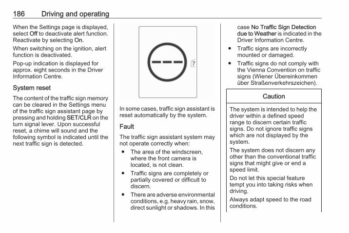
186 Driving and operating
When the Settings page is displayed,select Off to deactivate alert function.Reactivate by selecting On.When switching on the ignition, alertfunction is deactivated.Pop-up indication is displayed forapprox. eight seconds in the DriverInformation Centre.
System resetThe content of the traffic sign memorycan be cleared in the Settings menuof the traffic sign assistant page bypressing and holding SET/CLR on theturn signal lever. Upon successfulreset, a chime will sound and thefollowing symbol is indicated until thenext traffic sign is detected.
In some cases, traffic sign assistant isreset automatically by the system.
FaultThe traffic sign assistant system maynot operate correctly when:● The area of the windscreen,
where the front camera islocated, is not clean.
● Traffic signs are completely orpartially covered or difficult todiscern.
● There are adverse environmentalconditions, e.g. heavy rain, snow,direct sunlight or shadows. In this
case No Traffic Sign Detectiondue to Weather is indicated in theDriver Information Centre.
● Traffic signs are incorrectlymounted or damaged.
● Traffic signs do not comply withthe Vienna Convention on trafficsigns (Wiener Übereinkommenüber Straßenverkehrszeichen).
Caution
The system is intended to help thedriver within a defined speedrange to discern certain trafficsigns. Do not ignore traffic signswhich are not displayed by thesystem.The system does not discern anyother than the conventional trafficsigns that might give or end aspeed limit.Do not let this special featuretempt you into taking risks whendriving.Always adapt speed to the roadconditions.
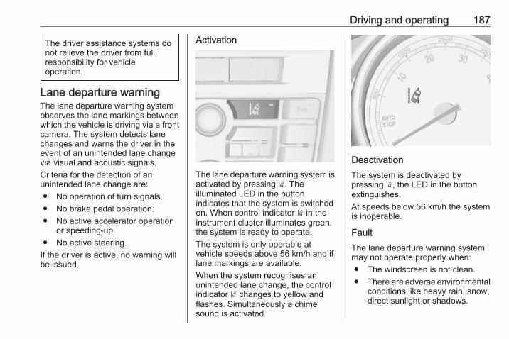
Driving and operating 187
The driver assistance systems donot relieve the driver from fullresponsibility for vehicleoperation.
Lane departure warningThe lane departure warning systemobserves the lane markings betweenwhich the vehicle is driving via a frontcamera. The system detects lanechanges and warns the driver in theevent of an unintended lane changevia visual and acoustic signals.Criteria for the detection of anunintended lane change are:● No operation of turn signals.● No brake pedal operation.● No active accelerator operation
or speeding-up.● No active steering.
If the driver is active, no warning willbe issued.
Activation
The lane departure warning system isactivated by pressing ). Theilluminated LED in the buttonindicates that the system is switchedon. When control indicator ) in theinstrument cluster illuminates green,the system is ready to operate.The system is only operable atvehicle speeds above 56 km/h and iflane markings are available.When the system recognises anunintended lane change, the controlindicator ) changes to yellow andflashes. Simultaneously a chimesound is activated.
DeactivationThe system is deactivated bypressing ), the LED in the buttonextinguishes.At speeds below 56 km/h the systemis inoperable.
FaultThe lane departure warning systemmay not operate properly when:● The windscreen is not clean.● There are adverse environmental
conditions like heavy rain, snow,direct sunlight or shadows.
188 Driving and operating
The system can not operate when nolane marking is detected. Fuel
Fuel for petrol enginesOnly use unleaded fuel that complieswith European standard EN 228 orE DIN 51626-1 or equivalent.The engine is capable of running withfuel that contains up to 10% ethanol(e.g. named E10).Use fuel with the recommendedoctane rating. A lower octane ratingcan reduce engine power and torqueand slightly increases fuelconsumption.
Caution
Do not use fuel or fuel additivesthat contain metallic compoundssuch as manganese-basedadditives. This may cause enginedamage.
Caution
Use of fuel that does not comply toEN 228 or E DIN 51626-1 orequivalent can lead to deposits orengine damage.
Caution
Use of fuel with a lower octanerating than the lowest possiblerating could lead to uncontrolledcombustion and engine damage.
The engine specific requirementsregarding octane rating are given inthe engine data overview 3 262. Acountry specific label at the fuel fillerflap can supersede the requirement.
Fuel for diesel enginesOnly use diesel fuel that complieswith EN 590.In countries outside the EuropeanUnion use Euro-Diesel fuel with asulphur concentration below 50 ppm.
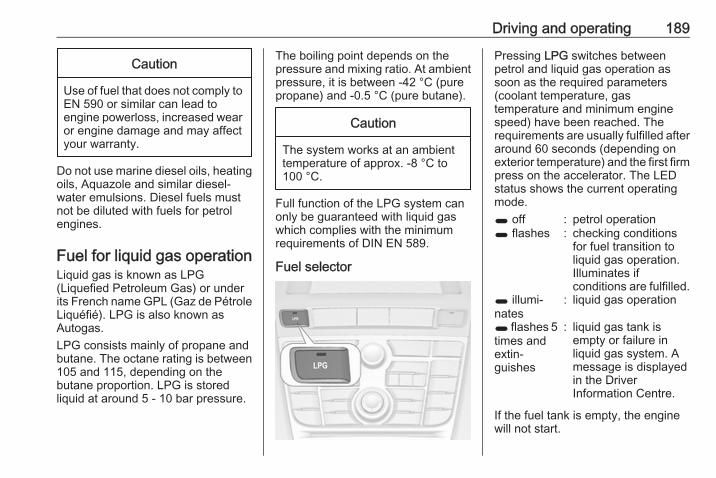
Driving and operating 189
Caution
Use of fuel that does not comply toEN 590 or similar can lead toengine powerloss, increased wearor engine damage and may affectyour warranty.
Do not use marine diesel oils, heatingoils, Aquazole and similar diesel-water emulsions. Diesel fuels mustnot be diluted with fuels for petrolengines.
Fuel for liquid gas operationLiquid gas is known as LPG(Liquefied Petroleum Gas) or underits French name GPL (Gaz de PétroleLiquéfié). LPG is also known asAutogas.LPG consists mainly of propane andbutane. The octane rating is between105 and 115, depending on thebutane proportion. LPG is storedliquid at around 5 - 10 bar pressure.
The boiling point depends on thepressure and mixing ratio. At ambientpressure, it is between -42 °C (purepropane) and -0.5 °C (pure butane).
Caution
The system works at an ambienttemperature of approx. -8 °C to100 °C.
Full function of the LPG system canonly be guaranteed with liquid gaswhich complies with the minimumrequirements of DIN EN 589.
Fuel selector
Pressing LPG switches betweenpetrol and liquid gas operation assoon as the required parameters(coolant temperature, gastemperature and minimum enginespeed) have been reached. Therequirements are usually fulfilled afteraround 60 seconds (depending onexterior temperature) and the first firmpress on the accelerator. The LEDstatus shows the current operatingmode.1 off : petrol operation1 flashes : checking conditions
for fuel transition toliquid gas operation.Illuminates ifconditions are fulfilled.
1 illumi‐nates
: liquid gas operation
1 flashes 5times andextin‐guishes
: liquid gas tank isempty or failure inliquid gas system. Amessage is displayedin the DriverInformation Centre.
If the fuel tank is empty, the enginewill not start.
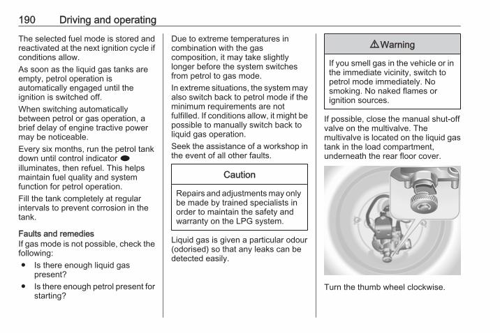
190 Driving and operating
The selected fuel mode is stored andreactivated at the next ignition cycle ifconditions allow.As soon as the liquid gas tanks areempty, petrol operation isautomatically engaged until theignition is switched off.When switching automaticallybetween petrol or gas operation, abrief delay of engine tractive powermay be noticeable.Every six months, run the petrol tankdown until control indicator iilluminates, then refuel. This helpsmaintain fuel quality and systemfunction for petrol operation.Fill the tank completely at regularintervals to prevent corrosion in thetank.
Faults and remediesIf gas mode is not possible, check thefollowing:● Is there enough liquid gas
present?● Is there enough petrol present for
starting?
Due to extreme temperatures incombination with the gascomposition, it may take slightlylonger before the system switchesfrom petrol to gas mode.In extreme situations, the system mayalso switch back to petrol mode if theminimum requirements are notfulfilled. If conditions allow, it might bepossible to manually switch back toliquid gas operation.Seek the assistance of a workshop inthe event of all other faults.
Caution
Repairs and adjustments may onlybe made by trained specialists inorder to maintain the safety andwarranty on the LPG system.
Liquid gas is given a particular odour(odorised) so that any leaks can bedetected easily.
9 Warning
If you smell gas in the vehicle or inthe immediate vicinity, switch topetrol mode immediately. Nosmoking. No naked flames orignition sources.
If possible, close the manual shut-offvalve on the multivalve. Themultivalve is located on the liquid gastank in the load compartment,underneath the rear floor cover.
Turn the thumb wheel clockwise.
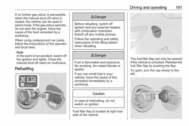
Driving and operating 191
If no further gas odour is perceptiblewhen the manual shut-off valve isclosed, the vehicle can be used inpetrol mode. If the gas odour persists,do not start the engine. Have thecause of the fault remedied by aworkshop.When using underground car parks,follow the instructions of the operatorand local laws.NoteIn the event of an accident, switch offthe ignition and lights. Close themanual shut-off valve on multivalve.
Refuelling
9 Danger
Before refuelling, switch offignition and any external heaterswith combustion chambers.Switch off any mobile phones.Follow the operating and safetyinstructions of the filling stationwhen refuelling.
9 Danger
Fuel is flammable and explosive.No smoking. No naked flames orsparks.If you can smell fuel in yourvehicle, have the cause of thisremedied immediately by aworkshop.
Caution
In case of misfuelling, do notswitch on ignition.
Fuel filler flap is located at right rearside of the vehicle.
The fuel filler flap can only be openedif the vehicle is unlocked. Release thefuel filler flap by pushing the flap.To open, turn the cap slowly to theleft.
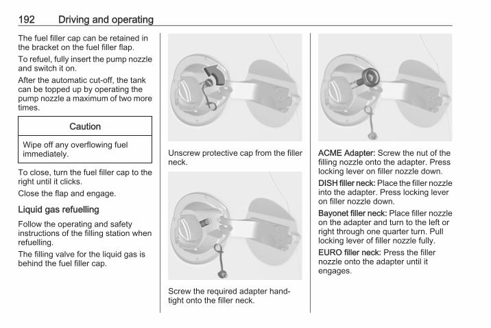
192 Driving and operating
The fuel filler cap can be retained inthe bracket on the fuel filler flap.To refuel, fully insert the pump nozzleand switch it on.After the automatic cut-off, the tankcan be topped up by operating thepump nozzle a maximum of two moretimes.
Caution
Wipe off any overflowing fuelimmediately.
To close, turn the fuel filler cap to theright until it clicks.Close the flap and engage.
Liquid gas refuellingFollow the operating and safetyinstructions of the filling station whenrefuelling.The filling valve for the liquid gas isbehind the fuel filler cap.
Unscrew protective cap from the fillerneck.
Screw the required adapter hand-tight onto the filler neck.
ACME Adapter: Screw the nut of thefilling nozzle onto the adapter. Presslocking lever on filler nozzle down.DISH filler neck: Place the filler nozzleinto the adapter. Press locking leveron filler nozzle down.Bayonet filler neck: Place filler nozzleon the adapter and turn to the left orright through one quarter turn. Pulllocking lever of filler nozzle fully.EURO filler neck: Press the fillernozzle onto the adapter until itengages.
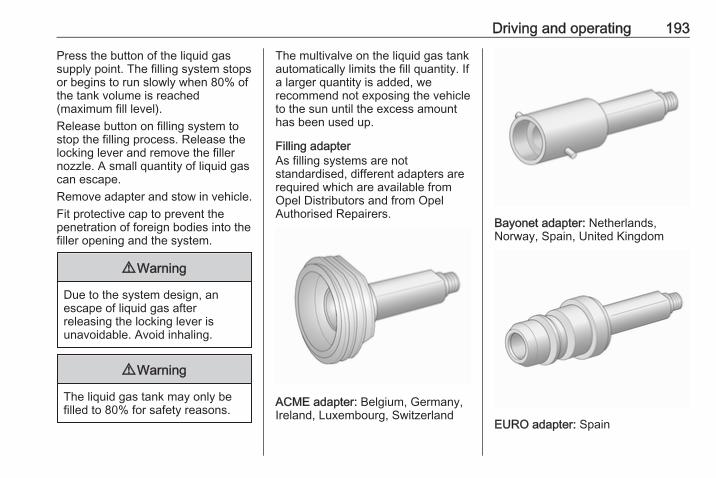
Driving and operating 193
Press the button of the liquid gassupply point. The filling system stopsor begins to run slowly when 80% ofthe tank volume is reached(maximum fill level).Release button on filling system tostop the filling process. Release thelocking lever and remove the fillernozzle. A small quantity of liquid gascan escape.Remove adapter and stow in vehicle.Fit protective cap to prevent thepenetration of foreign bodies into thefiller opening and the system.
9 Warning
Due to the system design, anescape of liquid gas afterreleasing the locking lever isunavoidable. Avoid inhaling.
9 Warning
The liquid gas tank may only befilled to 80% for safety reasons.
The multivalve on the liquid gas tankautomatically limits the fill quantity. Ifa larger quantity is added, werecommend not exposing the vehicleto the sun until the excess amounthas been used up.
Filling adapterAs filling systems are notstandardised, different adapters arerequired which are available fromOpel Distributors and from OpelAuthorised Repairers.
ACME adapter: Belgium, Germany,Ireland, Luxembourg, Switzerland
Bayonet adapter: Netherlands,Norway, Spain, United Kingdom
EURO adapter: Spain
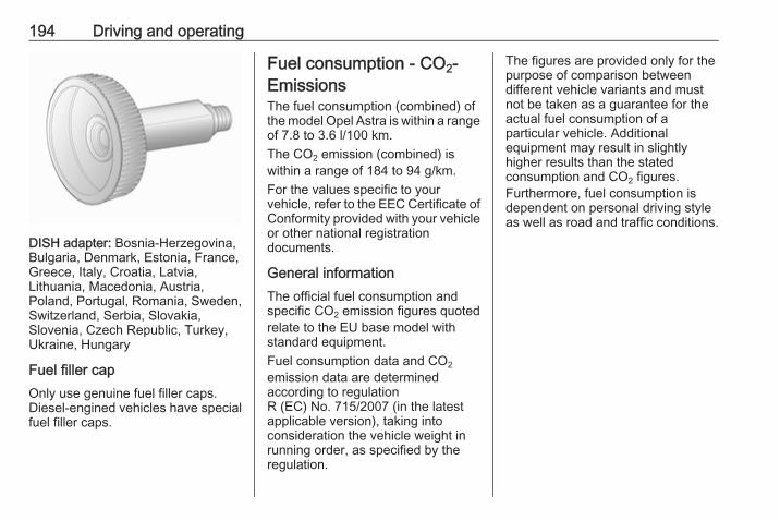
194 Driving and operating
DISH adapter: Bosnia-Herzegovina,Bulgaria, Denmark, Estonia, France,Greece, Italy, Croatia, Latvia,Lithuania, Macedonia, Austria,Poland, Portugal, Romania, Sweden,Switzerland, Serbia, Slovakia,Slovenia, Czech Republic, Turkey,Ukraine, Hungary
Fuel filler capOnly use genuine fuel filler caps.Diesel-engined vehicles have specialfuel filler caps.
Fuel consumption - CO2-EmissionsThe fuel consumption (combined) ofthe model Opel Astra is within a rangeof 7.8 to 3.6 l/100 km.The CO2 emission (combined) iswithin a range of 184 to 94 g/km.For the values specific to yourvehicle, refer to the EEC Certificate ofConformity provided with your vehicleor other national registrationdocuments.
General informationThe official fuel consumption andspecific CO2 emission figures quotedrelate to the EU base model withstandard equipment.Fuel consumption data and CO2emission data are determinedaccording to regulationR (EC) No. 715/2007 (in the latestapplicable version), taking intoconsideration the vehicle weight inrunning order, as specified by theregulation.
The figures are provided only for thepurpose of comparison betweendifferent vehicle variants and mustnot be taken as a guarantee for theactual fuel consumption of aparticular vehicle. Additionalequipment may result in slightlyhigher results than the statedconsumption and CO2 figures.Furthermore, fuel consumption isdependent on personal driving styleas well as road and traffic conditions.
Driving and operating 195
Trailer hitchGeneral informationOnly use towing equipment that hasbeen approved for your vehicle.Entrust retrofitting of towingequipment to a workshop. It may benecessary to make changes thataffect the cooling system, heatshields or other equipment.The bulb outage detection function fortrailer brake light cannot detect apartial bulb outage, e.g. in case of 4 x5 Watt bulbs, the function only detectslamp outage when only a single5 Watt lamp remains or none remain.Fitting of towing equipment couldcover the opening of the towing eye.If this is the case use the coupling ballbar for towing. Always keep thecoupling ball bar in the vehicle.
Driving characteristics andtowing tipsBefore attaching a trailer, lubricatethe coupling ball. However, do not doso if a stabiliser, which acts on thecoupling ball, is being used to reducesnaking movements.For trailers with low driving stabilityand caravan trailers with a permittedgross vehicle weight of more than1300 kg the use of a stabiliser isstrongly recommended when drivingabove 80 km/h.If the trailer starts snaking, drive moreslowly, do not attempt to correct thesteering and brake sharply ifnecessary.When driving downhill, drive in thesame gear as if driving uphill anddrive at a similar speed.Adjust tyre pressure to the valuespecified for full load 3 271.
Trailer towingTrailer loadsThe permissible trailer loads arevehicle and engine-dependentmaximum values which must not beexceeded. The actual trailer load isthe difference between the actualgross weight of the trailer and theactual coupling socket load with thetrailer coupled.The permissible trailer loads arespecified in the vehicle documents. Ingeneral, they are valid for gradientsup to max. 12%.The permitted trailer load applies upto the specified incline and up to analtitude of 1000 metres above sealevel. Since engine power decreasesas altitude increases due to the airbecoming thinner, therefore reducingclimbing ability, the permissible grosstrain weight also decreases by 10%for every 1000 metres of additionalaltitude. The gross train weight doesnot have to be reduced when drivingon roads with slight inclines (less than8%, e.g. motorways).
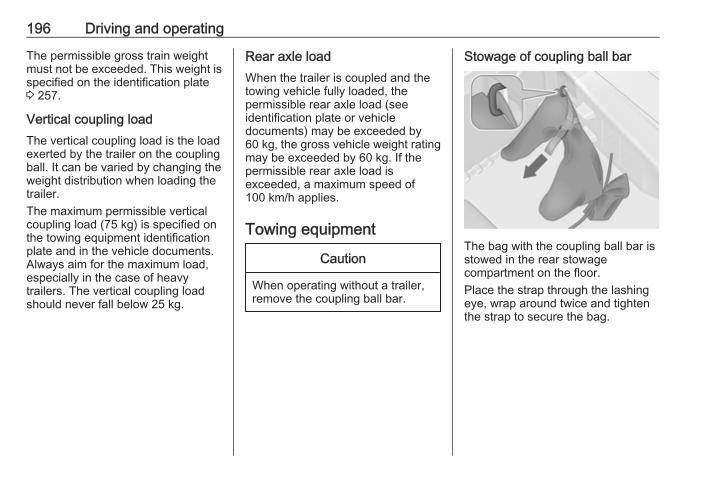
196 Driving and operating
The permissible gross train weightmust not be exceeded. This weight isspecified on the identification plate3 257.
Vertical coupling loadThe vertical coupling load is the loadexerted by the trailer on the couplingball. It can be varied by changing theweight distribution when loading thetrailer.The maximum permissible verticalcoupling load (75 kg) is specified onthe towing equipment identificationplate and in the vehicle documents.Always aim for the maximum load,especially in the case of heavytrailers. The vertical coupling loadshould never fall below 25 kg.
Rear axle loadWhen the trailer is coupled and thetowing vehicle fully loaded, thepermissible rear axle load (seeidentification plate or vehicledocuments) may be exceeded by60 kg, the gross vehicle weight ratingmay be exceeded by 60 kg. If thepermissible rear axle load isexceeded, a maximum speed of100 km/h applies.
Towing equipment
Caution
When operating without a trailer,remove the coupling ball bar.
Stowage of coupling ball bar
The bag with the coupling ball bar isstowed in the rear stowagecompartment on the floor.Place the strap through the lashingeye, wrap around twice and tightenthe strap to secure the bag.
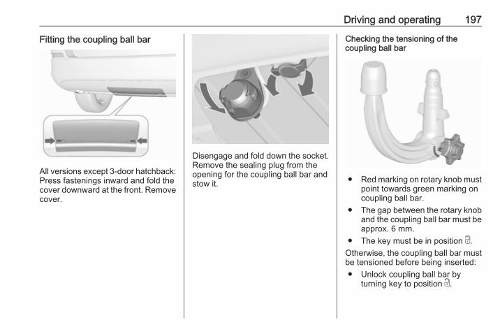
Driving and operating 197
Fitting the coupling ball bar
All versions except 3-door hatchback:Press fastenings inward and fold thecover downward at the front. Removecover.
Disengage and fold down the socket.Remove the sealing plug from theopening for the coupling ball bar andstow it.
Checking the tensioning of thecoupling ball bar
● Red marking on rotary knob mustpoint towards green marking oncoupling ball bar.
● The gap between the rotary knoband the coupling ball bar must beapprox. 6 mm.
● The key must be in position c.Otherwise, the coupling ball bar mustbe tensioned before being inserted:● Unlock coupling ball bar by
turning key to position c.
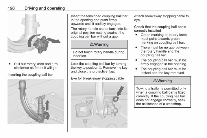
198 Driving and operating
● Pull out rotary knob and turnclockwise as far as it will go.
Inserting the coupling ball bar
Insert the tensioned coupling ball barin the opening and push firmlyupwards until it audibly engages.The rotary handle snaps back into itsoriginal position resting against thecoupling ball bar without a gap.
9 Warning
Do not touch rotary handle duringinsertion.
Lock the coupling ball bar by turningthe key to position e. Remove the keyand close the protective flap.
Eye for break-away stopping cable
Attach breakaway stopping cable toeye.
Check that the coupling ball bar iscorrectly installed● Green marking on rotary knob
must point towards greenmarking on coupling ball bar.
● There must be no gap betweenthe rotary handle and thecoupling ball bar.
● The coupling ball bar must befirmly engaged in the opening.
● The coupling ball bar must belocked and the key removed.
9 Warning
Towing a trailer is permitted onlywhen a coupling ball bar is fittedcorrectly. If the coupling ball bardoes not engage correctly, seekthe assistance of a workshop.
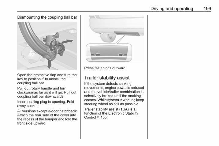
Driving and operating 199
Dismounting the coupling ball bar
Open the protective flap and turn thekey to position c to unlock thecoupling ball bar.Pull out rotary handle and turnclockwise as far as it will go. Pull outcoupling ball bar downwards.Insert sealing plug in opening. Foldaway socket.All versions except 3-door hatchback:Attach the rear side of the cover intothe recess of the bumper and fold thefront side upward.
Press fastenings outward.
Trailer stability assistIf the system detects snakingmovements, engine power is reducedand the vehicle/trailer combination isselectively braked until the snakingceases. While system is working keepsteering wheel as still as possible.Trailer stability assist (TSA) is afunction of the Electronic StabilityControl 3 155.
200 Vehicle care
Vehicle care
General Information ................... 201Accessories and vehiclemodifications .......................... 201
Vehicle storage ........................ 201End-of-life vehicle recovery ..... 202
Vehicle checks ........................... 202Performing work ...................... 202Bonnet ..................................... 202Engine oil ................................. 203Engine coolant ......................... 204Power steering fluid ................. 205Washer fluid ............................ 205Brakes ..................................... 206Brake fluid ............................... 206Vehicle battery ......................... 206Diesel fuel system bleeding ..... 208Wiper blade replacement ........ 208
Bulb replacement ....................... 209Halogen headlights .................. 209Adaptive forward lighting ......... 212Fog lights ................................. 213Front turn signal lights ............. 215Tail lights ................................. 217Side turn signal lights .............. 220Number plate light ................... 222
Interior lights ............................ 222Instrument panel illumination ... 222
Electrical system ........................ 223Fuses ....................................... 223Engine compartment fuse box . 224Instrument panel fuse box ....... 226Load compartment fuse box .... 227
Vehicle tools .............................. 228Tools ........................................ 228
Wheels and tyres ....................... 230Winter tyres ............................. 230Tyre designations .................... 230Tyre pressure .......................... 230Tyre pressure monitoringsystem .................................... 232
Tread depth ............................. 235Changing tyre and wheel size . 235Wheel covers ........................... 236Tyre chains .............................. 236Tyre repair kit .......................... 236Wheel changing ....................... 239Spare wheel ............................ 243
Jump starting ............................. 247Towing ....................................... 248
Towing the vehicle ................... 248Towing another vehicle ........... 249
Appearance care ....................... 250Exterior care ............................ 250Interior care ............................. 253
Vehicle care 201
General InformationAccessories and vehiclemodificationsWe recommend the use of genuineparts and accessories and factoryapproved parts specific for yourvehicle type. We cannot assess orguarantee reliability of other products- even if they have a regulatory orotherwise granted approval.Any modification, conversion or otherchanges made to standard vehiclespecifications (including, withoutlimitation, software modifications,modifications of the electronic controlunits) may invalidate the warrantyoffered by Opel. Furthermore, suchchanges may impact fuelconsumption, CO2 emissions andother emissions of the vehicle andcause the vehicle to no longerconform to the type approval,impacting the validity of your vehicleregistration.
Caution
When transporting the vehicle ona train or on a recovery vehicle, themud flaps might be damaged.
Vehicle storageStorage for a long period of timeIf the vehicle is to be stored for severalmonths:● Wash and wax the vehicle.● Have the wax in the engine
compartment and underbodychecked.
● Clean and preserve the rubberseals.
● Fill up fuel tank completely.● Change the engine oil.● Drain the washer fluid reservoir.● Check the coolant antifreeze and
corrosion protection.● Adjust tyre pressure to the value
specified for full load.
● Park the vehicle in a dry, wellventilated place. Engage first orreverse gear or set selector leverto P. Prevent the vehicle fromrolling.
● Do not apply the parking brake.● Open the bonnet, close all doors
and lock the vehicle.● Disconnect the clamp from the
negative terminal of the vehiclebattery. Beware that all systemsare not functional, e.g. anti-theftalarm system.
Putting back into operationWhen the vehicle is to be put back intooperation:● Connect the clamp to the
negative terminal of the vehiclebattery. Activate the electronicsof the power windows.
● Check tyre pressure.● Fill up the washer fluid reservoir.● Check the engine oil level.● Check the coolant level.● Fit the number plate if necessary.

202 Vehicle care
End-of-life vehicle recoveryInformation on end-of-life vehiclerecovery centres and the recycling ofend-of-life vehicles is available on ourwebsite, where legally required. Onlyentrust this work to an authorisedrecycling centre.Gas vehicles must be recycled by aservice centre authorised for gasvehicles.
Vehicle checksPerforming work
9 Warning
Only perform engine compartmentchecks when the ignition is off.The cooling fan may startoperating even if the ignition is off.
9 Danger
The ignition system and Xenonheadlights use extremely highvoltage. Do not touch.
BonnetOpening
Pull the release lever and return it toits original position.
Vehicle care 203
Move the safety catch sideways to theleft vehicle side and open the bonnet.
Secure the bonnet support.
If the bonnet is opened during anAutostop, the engine will be restartedautomatically for safety reasons.
ClosingBefore closing the bonnet, press thesupport into the holder.Lower the bonnet and allow it to fallinto the latch from a low height(20-25 cm). Check that the bonnet isengaged.
Caution
Do not press the bonnet into thelatch, to avoid dents.
Engine oilCheck the engine oil level manuallyon a regular basis to prevent damageto the engine. Ensure that the correctspecification of oil is used.Recommended fluids and lubricants3 255.The maximum engine oilconsumption is 0.6 l per 1000 km.
Check with the vehicle on a levelsurface. The engine must be atoperating temperature and switchedoff for at least five minutes.Pull out the dipstick, wipe it clean,insert it to the stop on the handle, pullout and read the engine oil level.Insert dipstick to the stop on thehandle and make half a turn.
Different dipsticks are useddepending on engine variant.
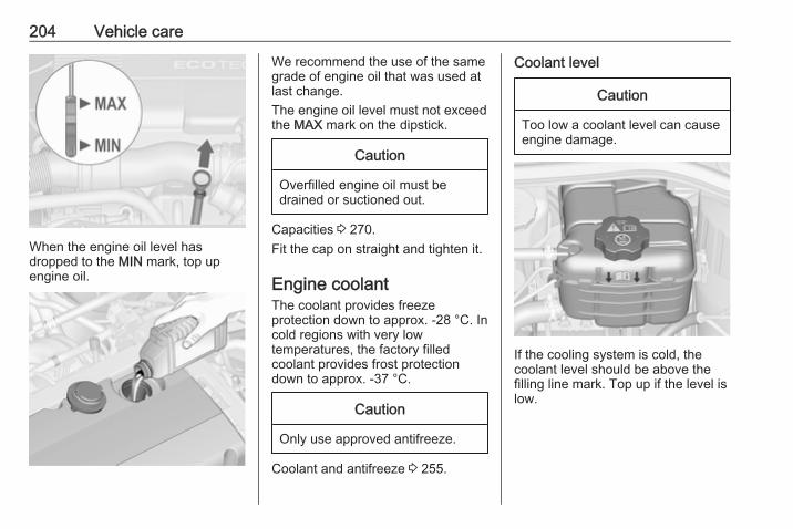
204 Vehicle care
When the engine oil level hasdropped to the MIN mark, top upengine oil.
We recommend the use of the samegrade of engine oil that was used atlast change.The engine oil level must not exceedthe MAX mark on the dipstick.
Caution
Overfilled engine oil must bedrained or suctioned out.
Capacities 3 270.Fit the cap on straight and tighten it.
Engine coolantThe coolant provides freezeprotection down to approx. -28 °C. Incold regions with very lowtemperatures, the factory filledcoolant provides frost protectiondown to approx. -37 °C.
Caution
Only use approved antifreeze.
Coolant and antifreeze 3 255.
Coolant level
Caution
Too low a coolant level can causeengine damage.
If the cooling system is cold, thecoolant level should be above thefilling line mark. Top up if the level islow.

Vehicle care 205
9 Warning
Allow the engine to cool beforeopening the cap. Carefully openthe cap, relieving the pressureslowly.
To top up, use a 1:1 mixture ofapproved coolant concentrate mixedwith clean tap water. If no coolantconcentrate is available, use cleantap water. Install the cap tightly. Havethe coolant concentration checkedand have the cause of the coolantloss remedied by a workshop.
Power steering fluid
Caution
Extremely small amounts ofcontamination can cause steeringsystem damage and cause it to notwork properly. Do not allowcontaminates to contact the fluidside of the reservoir cap/dipstick orfrom entering the reservoir.
Power steering fluid level normallydoes not have to be checked. If anunusual noise sounds during steeringor the power steering reactsunusually, seek the assistance of aworkshop.
Washer fluid
Fill with clean water mixed with asuitable quantity of approvedwindscreen washer fluid whichcontains antifreeze.
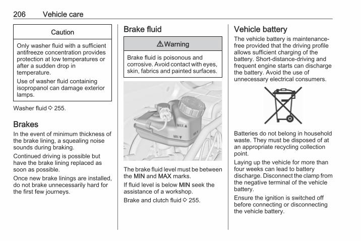
206 Vehicle care
Caution
Only washer fluid with a sufficientantifreeze concentration providesprotection at low temperatures orafter a sudden drop intemperature.Use of washer fluid containingisopropanol can damage exteriorlamps.
Washer fluid 3 255.
BrakesIn the event of minimum thickness ofthe brake lining, a squealing noisesounds during braking.Continued driving is possible buthave the brake lining replaced assoon as possible.Once new brake linings are installed,do not brake unnecessarily hard forthe first few journeys.
Brake fluid
9 Warning
Brake fluid is poisonous andcorrosive. Avoid contact with eyes,skin, fabrics and painted surfaces.
The brake fluid level must be betweenthe MIN and MAX marks.If fluid level is below MIN seek theassistance of a workshop.Brake and clutch fluid 3 255.
Vehicle batteryThe vehicle battery is maintenance-free provided that the driving profileallows sufficient charging of thebattery. Short-distance-driving andfrequent engine starts can dischargethe battery. Avoid the use ofunnecessary electrical consumers.
Batteries do not belong in householdwaste. They must be disposed of atan appropriate recycling collectionpoint.Laying up the vehicle for more thanfour weeks can lead to batterydischarge. Disconnect the clamp fromthe negative terminal of the vehiclebattery.Ensure the ignition is switched offbefore connecting or disconnectingthe vehicle battery.
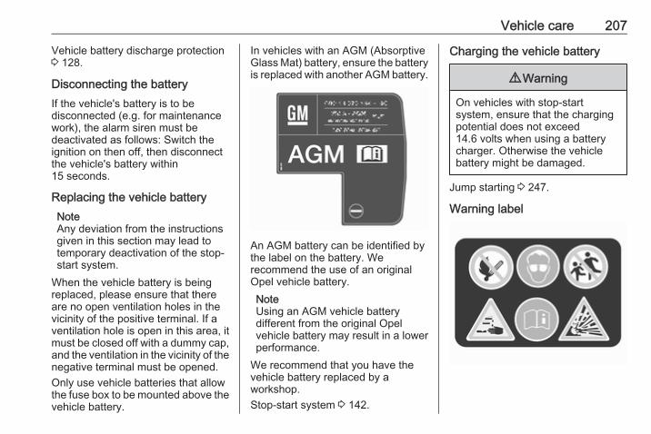
Vehicle care 207
Vehicle battery discharge protection3 128.
Disconnecting the batteryIf the vehicle's battery is to bedisconnected (e.g. for maintenancework), the alarm siren must bedeactivated as follows: Switch theignition on then off, then disconnectthe vehicle's battery within15 seconds.
Replacing the vehicle batteryNoteAny deviation from the instructionsgiven in this section may lead totemporary deactivation of the stop-start system.
When the vehicle battery is beingreplaced, please ensure that thereare no open ventilation holes in thevicinity of the positive terminal. If aventilation hole is open in this area, itmust be closed off with a dummy cap,and the ventilation in the vicinity of thenegative terminal must be opened.Only use vehicle batteries that allowthe fuse box to be mounted above thevehicle battery.
In vehicles with an AGM (AbsorptiveGlass Mat) battery, ensure the batteryis replaced with another AGM battery.
An AGM battery can be identified bythe label on the battery. Werecommend the use of an originalOpel vehicle battery.NoteUsing an AGM vehicle batterydifferent from the original Opelvehicle battery may result in a lowerperformance.
We recommend that you have thevehicle battery replaced by aworkshop.Stop-start system 3 142.
Charging the vehicle battery
9 Warning
On vehicles with stop-startsystem, ensure that the chargingpotential does not exceed14.6 volts when using a batterycharger. Otherwise the vehiclebattery might be damaged.
Jump starting 3 247.
Warning label
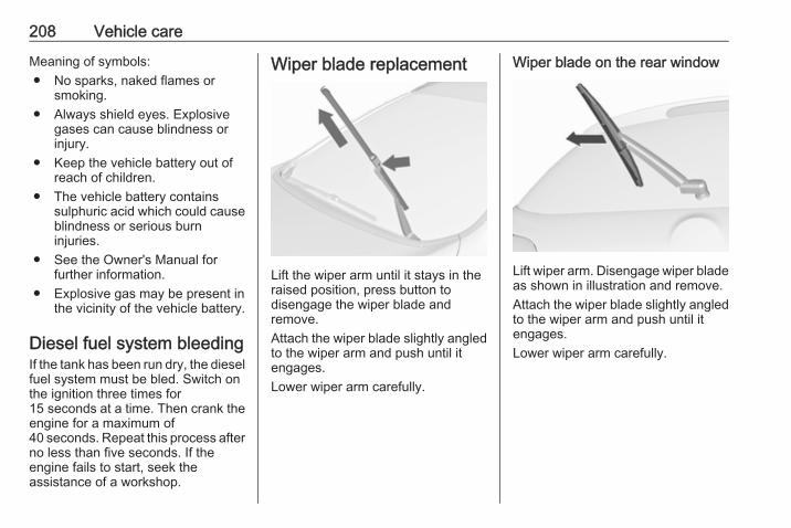
208 Vehicle care
Meaning of symbols:● No sparks, naked flames or
smoking.● Always shield eyes. Explosive
gases can cause blindness orinjury.
● Keep the vehicle battery out ofreach of children.
● The vehicle battery containssulphuric acid which could causeblindness or serious burninjuries.
● See the Owner's Manual forfurther information.
● Explosive gas may be present inthe vicinity of the vehicle battery.
Diesel fuel system bleedingIf the tank has been run dry, the dieselfuel system must be bled. Switch onthe ignition three times for15 seconds at a time. Then crank theengine for a maximum of40 seconds. Repeat this process afterno less than five seconds. If theengine fails to start, seek theassistance of a workshop.
Wiper blade replacement
Lift the wiper arm until it stays in theraised position, press button todisengage the wiper blade andremove.Attach the wiper blade slightly angledto the wiper arm and push until itengages.Lower wiper arm carefully.
Wiper blade on the rear window
Lift wiper arm. Disengage wiper bladeas shown in illustration and remove.Attach the wiper blade slightly angledto the wiper arm and push until itengages.Lower wiper arm carefully.
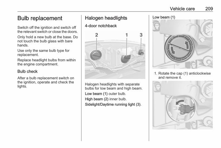
Vehicle care 209
Bulb replacementSwitch off the ignition and switch offthe relevant switch or close the doors.Only hold a new bulb at the base. Donot touch the bulb glass with barehands.Use only the same bulb type forreplacement.Replace headlight bulbs from withinthe engine compartment.
Bulb checkAfter a bulb replacement switch onthe ignition, operate and check thelights.
Halogen headlights4-door notchback
Halogen headlights with separatebulbs for low beam and high beam.Low beam (1) outer bulb.High beam (2) inner bulb.Sidelight/Daytime running light (3).
Low beam (1)
1. Rotate the cap (1) anticlockwiseand remove it.
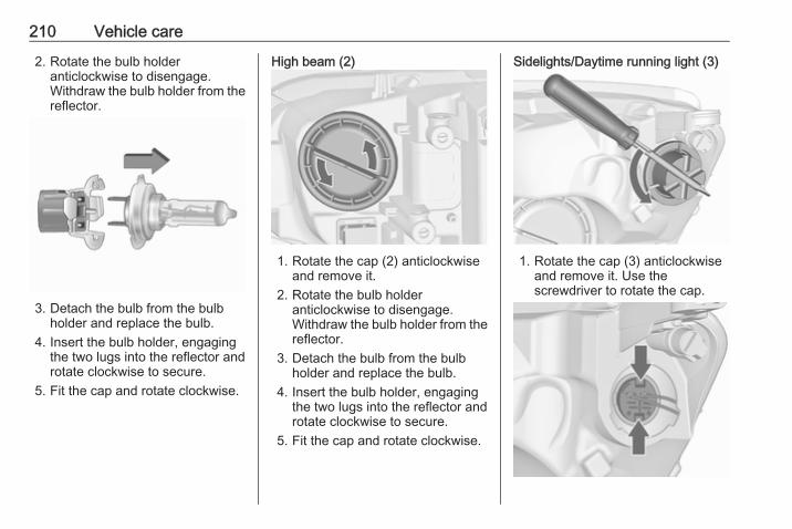
210 Vehicle care
2. Rotate the bulb holderanticlockwise to disengage.Withdraw the bulb holder from thereflector.
3. Detach the bulb from the bulbholder and replace the bulb.
4. Insert the bulb holder, engagingthe two lugs into the reflector androtate clockwise to secure.
5. Fit the cap and rotate clockwise.
High beam (2)
1. Rotate the cap (2) anticlockwiseand remove it.
2. Rotate the bulb holderanticlockwise to disengage.Withdraw the bulb holder from thereflector.
3. Detach the bulb from the bulbholder and replace the bulb.
4. Insert the bulb holder, engagingthe two lugs into the reflector androtate clockwise to secure.
5. Fit the cap and rotate clockwise.
Sidelights/Daytime running light (3)
1. Rotate the cap (3) anticlockwiseand remove it. Use thescrewdriver to rotate the cap.
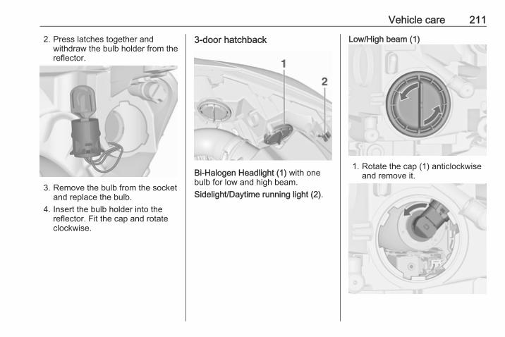
Vehicle care 211
2. Press latches together andwithdraw the bulb holder from thereflector.
3. Remove the bulb from the socketand replace the bulb.
4. Insert the bulb holder into thereflector. Fit the cap and rotateclockwise.
3-door hatchback
Bi-Halogen Headlight (1) with onebulb for low and high beam.Sidelight/Daytime running light (2).
Low/High beam (1)
1. Rotate the cap (1) anticlockwiseand remove it.
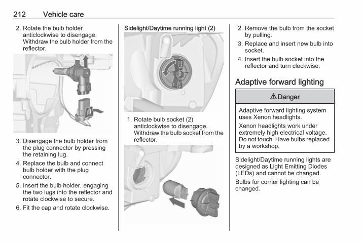
212 Vehicle care
2. Rotate the bulb holderanticlockwise to disengage.Withdraw the bulb holder from thereflector.
3. Disengage the bulb holder fromthe plug connector by pressingthe retaining lug.
4. Replace the bulb and connectbulb holder with the plugconnector.
5. Insert the bulb holder, engagingthe two lugs into the reflector androtate clockwise to secure.
6. Fit the cap and rotate clockwise.
Sidelight/Daytime running light (2)
1. Rotate bulb socket (2)anticlockwise to disengage.Withdraw the bulb socket from thereflector.
2. Remove the bulb from the socketby pulling.
3. Replace and insert new bulb intosocket.
4. Insert the bulb socket into thereflector and turn clockwise.
Adaptive forward lighting
9 Danger
Adaptive forward lighting systemuses Xenon headlights.Xenon headlights work underextremely high electrical voltage.Do not touch. Have bulbs replacedby a workshop.
Sidelight/Daytime running lights aredesigned as Light Emitting Diodes(LEDs) and cannot be changed.Bulbs for corner lighting can bechanged.
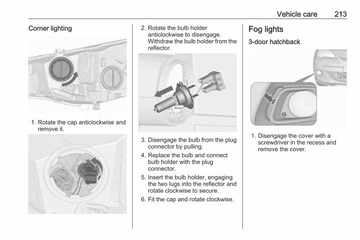
Vehicle care 213
Corner lighting
1. Rotate the cap anticlockwise andremove it.
2. Rotate the bulb holderanticlockwise to disengage.Withdraw the bulb holder from thereflector.
3. Disengage the bulb from the plugconnector by pulling.
4. Replace the bulb and connectbulb holder with the plugconnector.
5. Insert the bulb holder, engagingthe two lugs into the reflector androtate clockwise to secure.
6. Fit the cap and rotate clockwise.
Fog lights3-door hatchback
1. Disengage the cover with ascrewdriver in the recess andremove the cover.
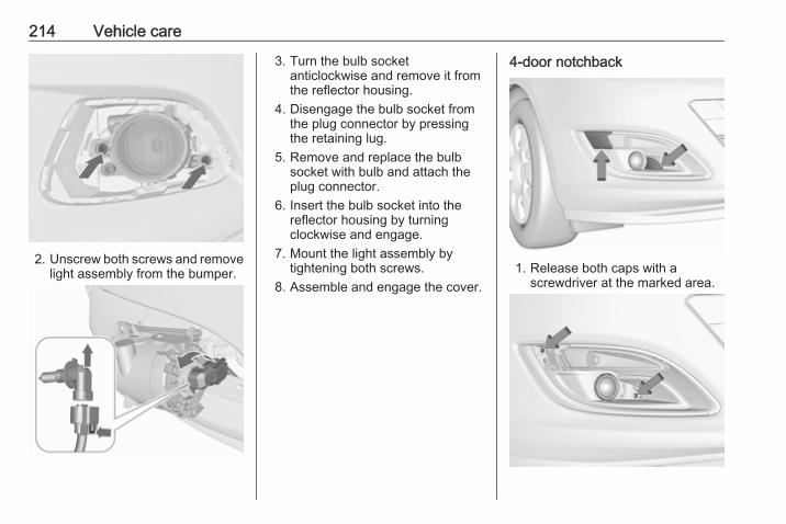
214 Vehicle care
2. Unscrew both screws and removelight assembly from the bumper.
3. Turn the bulb socketanticlockwise and remove it fromthe reflector housing.
4. Disengage the bulb socket fromthe plug connector by pressingthe retaining lug.
5. Remove and replace the bulbsocket with bulb and attach theplug connector.
6. Insert the bulb socket into thereflector housing by turningclockwise and engage.
7. Mount the light assembly bytightening both screws.
8. Assemble and engage the cover.
4-door notchback
1. Release both caps with ascrewdriver at the marked area.

Vehicle care 215
2. Unscrew both screws and removeturn light assembly from thebumper.
3. Unscrew three screws andremove fog light assembly fromthe bumper.
4. Turn the bulb socketanticlockwise and remove it fromthe reflector housing.
5. Disengage the bulb socket fromthe plug connector by pressingthe retaining lug.
6. Replace and insert bulb socketinto the reflector housing, turnbulb socket clockwise and attachthe plug connector.
7. Attach fog light assembly into thebumper and fix with three screws.
8. Attach turn light assembly into thebumper and fix with two screws.
9. Engage both caps.
Front turn signal lights3-door hatchback
1. Rotate cap (1) anticlockwise andremove it.
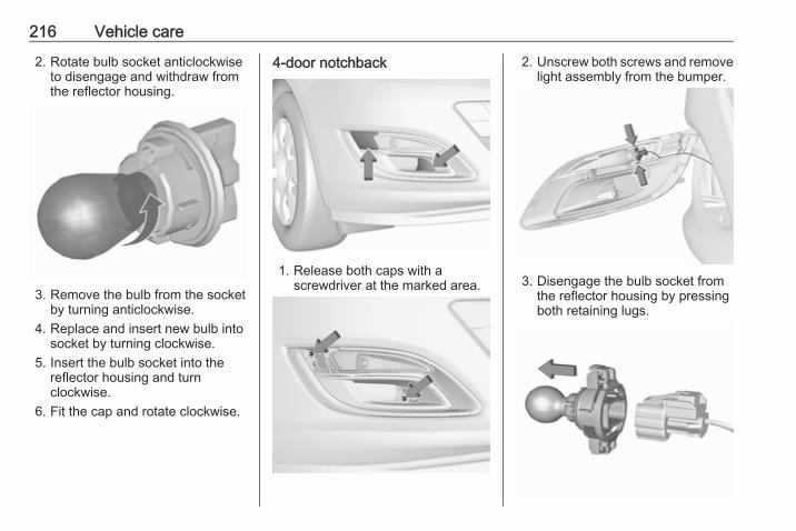
216 Vehicle care
2. Rotate bulb socket anticlockwiseto disengage and withdraw fromthe reflector housing.
3. Remove the bulb from the socketby turning anticlockwise.
4. Replace and insert new bulb intosocket by turning clockwise.
5. Insert the bulb socket into thereflector housing and turnclockwise.
6. Fit the cap and rotate clockwise.
4-door notchback
1. Release both caps with ascrewdriver at the marked area.
2. Unscrew both screws and removelight assembly from the bumper.
3. Disengage the bulb socket fromthe reflector housing by pressingboth retaining lugs.

Vehicle care 217
4. Disengage the plug connectorfrom the bulb socket by pressingthe retaining lug.
5. Remove and replace the bulbsocket with bulb.
6. Insert the bulb socket into thereflector housing and attach theplug connector.
7. Attach light assembly into thebumper and fix with both screws.
8. Engage both caps.
4-door notchback with Sport/GSi frontbumperThe bulbs are accessible frombeneath the vehicle.
1. Disengage the spring clip andthen swivel it backwards.
2. Pull the bulb socket with bulb outof the reflector housing.
3. Disengage the bulb socket fromthe plug connector by pressingthe retaining lug.
4. Remove and replace the bulbsocket with bulb.
5. Attach the plug connector.6. Insert the bulb socket into the
reflector housing.7. Swivel the spring clip forwards
and engage.
Tail lights3-door hatchback
1. Release the cover on therespective side and remove it.
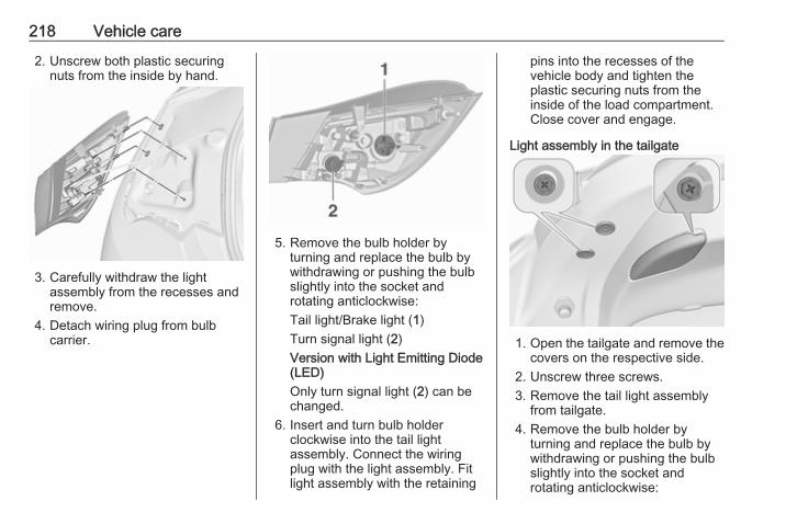
218 Vehicle care
2. Unscrew both plastic securingnuts from the inside by hand.
3. Carefully withdraw the lightassembly from the recesses andremove.
4. Detach wiring plug from bulbcarrier.
5. Remove the bulb holder byturning and replace the bulb bywithdrawing or pushing the bulbslightly into the socket androtating anticlockwise:Tail light/Brake light (1)Turn signal light (2)Version with Light Emitting Diode(LED)Only turn signal light (2) can bechanged.
6. Insert and turn bulb holderclockwise into the tail lightassembly. Connect the wiringplug with the light assembly. Fitlight assembly with the retaining
pins into the recesses of thevehicle body and tighten theplastic securing nuts from theinside of the load compartment.Close cover and engage.
Light assembly in the tailgate
1. Open the tailgate and remove thecovers on the respective side.
2. Unscrew three screws.3. Remove the tail light assembly
from tailgate.4. Remove the bulb holder by
turning and replace the bulb bywithdrawing or pushing the bulbslightly into the socket androtating anticlockwise:
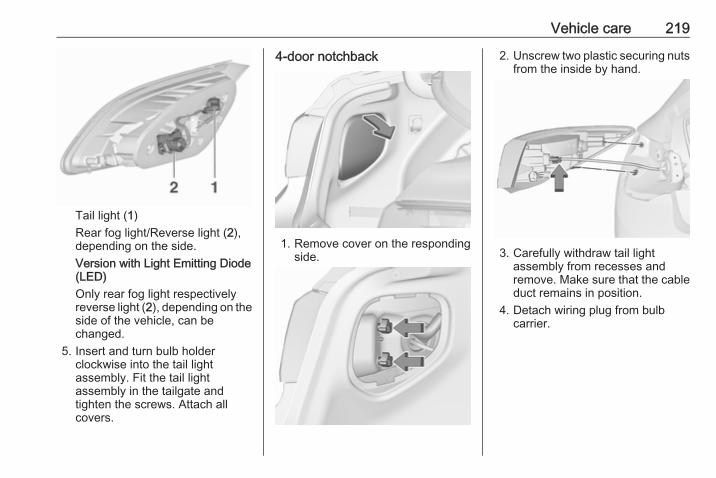
Vehicle care 219
Tail light (1)Rear fog light/Reverse light (2),depending on the side.Version with Light Emitting Diode(LED)Only rear fog light respectivelyreverse light (2), depending on theside of the vehicle, can bechanged.
5. Insert and turn bulb holderclockwise into the tail lightassembly. Fit the tail lightassembly in the tailgate andtighten the screws. Attach allcovers.
4-door notchback
1. Remove cover on the respondingside.
2. Unscrew two plastic securing nutsfrom the inside by hand.
3. Carefully withdraw tail lightassembly from recesses andremove. Make sure that the cableduct remains in position.
4. Detach wiring plug from bulbcarrier.
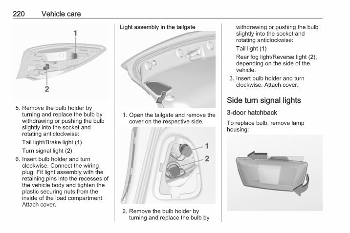
220 Vehicle care
5. Remove the bulb holder byturning and replace the bulb bywithdrawing or pushing the bulbslightly into the socket androtating anticlockwise:Tail light/Brake light (1)Turn signal light (2)
6. Insert bulb holder and turnclockwise. Connect the wiringplug. Fit light assembly with theretaining pins into the recesses ofthe vehicle body and tighten theplastic securing nuts from theinside of the load compartment.Attach cover.
Light assembly in the tailgate
1. Open the tailgate and remove thecover on the respective side.
2. Remove the bulb holder byturning and replace the bulb by
withdrawing or pushing the bulbslightly into the socket androtating anticlockwise:Tail light (1)Rear fog light/Reverse light (2),depending on the side of thevehicle.
3. Insert bulb holder and turnclockwise. Attach cover.
Side turn signal lights3-door hatchbackTo replace bulb, remove lamphousing:
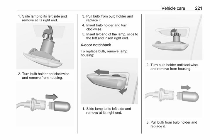
Vehicle care 221
1. Slide lamp to its left side andremove at its right end.
2. Turn bulb holder anticlockwiseand remove from housing.
3. Pull bulb from bulb holder andreplace it.
4. Insert bulb holder and turnclockwise.
5. Insert left end of the lamp, slide tothe left and insert right end.
4-door notchbackTo replace bulb, remove lamphousing:
1. Slide lamp to its left side andremove at its right end.
2. Turn bulb holder anticlockwiseand remove from housing.
3. Pull bulb from bulb holder andreplace it.
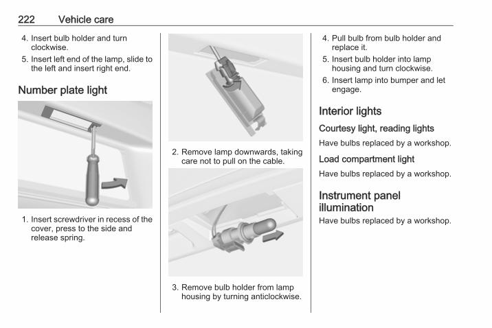
222 Vehicle care
4. Insert bulb holder and turnclockwise.
5. Insert left end of the lamp, slide tothe left and insert right end.
Number plate light
1. Insert screwdriver in recess of thecover, press to the side andrelease spring.
2. Remove lamp downwards, takingcare not to pull on the cable.
3. Remove bulb holder from lamphousing by turning anticlockwise.
4. Pull bulb from bulb holder andreplace it.
5. Insert bulb holder into lamphousing and turn clockwise.
6. Insert lamp into bumper and letengage.
Interior lightsCourtesy light, reading lightsHave bulbs replaced by a workshop.
Load compartment lightHave bulbs replaced by a workshop.
Instrument panelilluminationHave bulbs replaced by a workshop.
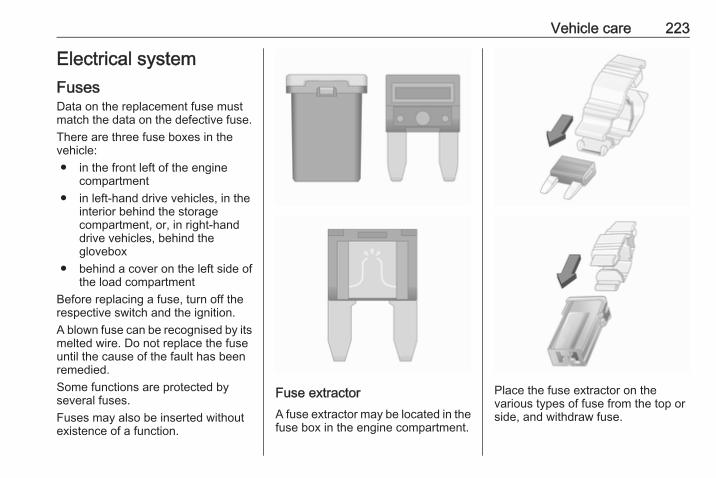
Vehicle care 223
Electrical systemFusesData on the replacement fuse mustmatch the data on the defective fuse.There are three fuse boxes in thevehicle:● in the front left of the engine
compartment● in left-hand drive vehicles, in the
interior behind the storagecompartment, or, in right-handdrive vehicles, behind theglovebox
● behind a cover on the left side ofthe load compartment
Before replacing a fuse, turn off therespective switch and the ignition.A blown fuse can be recognised by itsmelted wire. Do not replace the fuseuntil the cause of the fault has beenremedied.Some functions are protected byseveral fuses.Fuses may also be inserted withoutexistence of a function.
Fuse extractorA fuse extractor may be located in thefuse box in the engine compartment.
Place the fuse extractor on thevarious types of fuse from the top orside, and withdraw fuse.
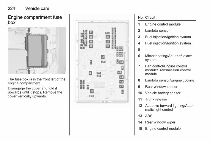
224 Vehicle care
Engine compartment fusebox
The fuse box is in the front left of theengine compartment.Disengage the cover and fold itupwards until it stops. Remove thecover vertically upwards.
No. Circuit
1 Engine control module
2 Lambda sensor
3 Fuel injection/Ignition system
4 Fuel injection/Ignition system
5 –
6 Mirror heating/Anti-theft alarmsystem
7 Fan control/Engine controlmodule/Transmission controlmodule
8 Lambda sensor/Engine cooling
9 Rear window sensor
10 Vehicle battery sensor
11 Trunk release
12 Adaptive forward lighting/Auto‐matic light control
13 ABS
14 Rear window wiper
15 Engine control module
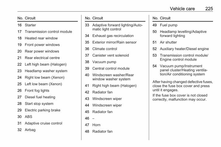
Vehicle care 225
No. Circuit
16 Starter
17 Transmission control module
18 Heated rear window
19 Front power windows
20 Rear power windows
21 Rear electrical centre
22 Left high beam (Halogen)
23 Headlamp washer system
24 Right low beam (Xenon)
25 Left low beam (Xenon)
26 Front fog lights
27 Diesel fuel heating
28 Start stop system
29 Electric parking brake
30 ABS
31 Adaptive cruise control
32 Airbag
No. Circuit
33 Adaptive forward lighting/Auto‐matic light control
34 Exhaust gas recirculation
35 Exterior mirror/Rain sensor
36 Climate control
37 Canister vent solenoid
38 Vacuum pump
39 Central control module
40 Windscreen washer/Rearwindow washer system
41 Right high beam (Halogen)
42 Radiator fan
43 Windscreen wiper
44 Windscreen wiper
45 Radiator fan
46 –
47 Horn
48 Radiator fan
No. Circuit
49 Fuel pump
50 Headlamp levelling/Adaptiveforward lighting
51 Air shutter
52 Auxiliary heater/Diesel engine
53 Transmission control module/Engine control module
54 Vacuum pump/Instrumentpanel cluster/Heating ventila‐tion/Air conditioning system
After having changed defective fuses,close the fuse box cover and pressuntil it engages.If the fuse box cover is not closedcorrectly, malfunction may occur.
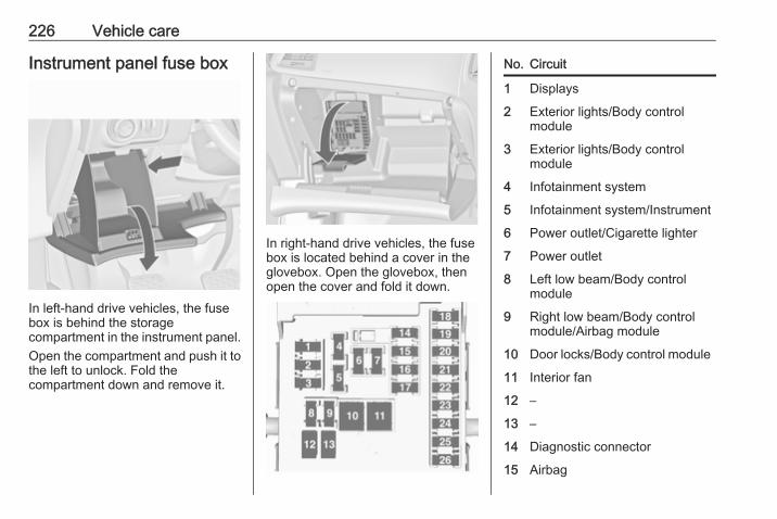
226 Vehicle care
Instrument panel fuse box
In left-hand drive vehicles, the fusebox is behind the storagecompartment in the instrument panel.Open the compartment and push it tothe left to unlock. Fold thecompartment down and remove it.
In right-hand drive vehicles, the fusebox is located behind a cover in theglovebox. Open the glovebox, thenopen the cover and fold it down.
No. Circuit
1 Displays
2 Exterior lights/Body controlmodule
3 Exterior lights/Body controlmodule
4 Infotainment system
5 Infotainment system/Instrument
6 Power outlet/Cigarette lighter
7 Power outlet
8 Left low beam/Body controlmodule
9 Right low beam/Body controlmodule/Airbag module
10 Door locks/Body control module
11 Interior fan
12 –
13 –
14 Diagnostic connector
15 Airbag
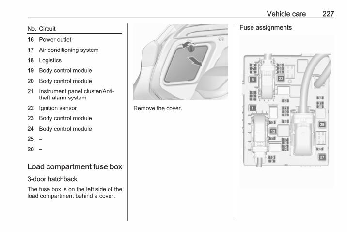
Vehicle care 227
No. Circuit
16 Power outlet
17 Air conditioning system
18 Logistics
19 Body control module
20 Body control module
21 Instrument panel cluster/Anti-theft alarm system
22 Ignition sensor
23 Body control module
24 Body control module
25 –
26 –
Load compartment fuse box3-door hatchbackThe fuse box is on the left side of theload compartment behind a cover.
Remove the cover.
Fuse assignments
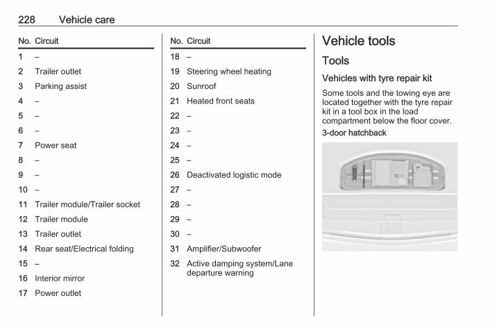
228 Vehicle care
No. Circuit
1 –
2 Trailer outlet
3 Parking assist
4 –
5 –
6 –
7 Power seat
8 –
9 –
10 –
11 Trailer module/Trailer socket
12 Trailer module
13 Trailer outlet
14 Rear seat/Electrical folding
15 –
16 Interior mirror
17 Power outlet
No. Circuit
18 –
19 Steering wheel heating
20 Sunroof
21 Heated front seats
22 –
23 –
24 –
25 –
26 Deactivated logistic mode
27 –
28 –
29 –
30 –
31 Amplifier/Subwoofer
32 Active damping system/Lanedeparture warning
Vehicle toolsToolsVehicles with tyre repair kitSome tools and the towing eye arelocated together with the tyre repairkit in a tool box in the loadcompartment below the floor cover.3-door hatchback
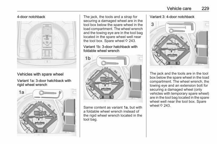
Vehicle care 229
4-door notchback
Vehicles with spare wheelVariant 1a: 3-door hatchback withrigid wheel wrench
The jack, the tools and a strap forsecuring a damaged wheel are in thetool box below the spare wheel in theload compartment. The wheel wrenchand the towing eye are in the tool baglocated in the spare wheel well nearthe tool box. Spare wheel 3 243.Variant 1b: 3-door hatchback withfoldable wheel wrench
Same content as variant 1a, but witha foldable wheel wrench instead ofthe rigid wheel wrench located in thetool bag.
Variant 3: 4-door notchback
The jack and the tools are in the toolbox below the spare wheel in the loadcompartment. The wheel wrench, thetowing eye and an extension bolt forsecuring a damaged wheel (onlyvehicles with temporary spare wheel)are in the tool bag located in the sparewheel well near the tool box. Sparewheel 3 243.
230 Vehicle care
Wheels and tyres
Tyre condition, wheel conditionDrive over edges slowly and at rightangles if possible. Driving over sharpedges can cause tyre and wheeldamage. Do not trap tyres on the kerbwhen parking.Regularly check the wheels fordamage. Seek the assistance of aworkshop in the event of damage orunusual wear.
Winter tyresWinter tyres improve driving safety attemperatures below 7 °C and shouldtherefore be fitted on all wheels.In accordance with country-specificregulations, affix the speed sticker inthe driver's field of view.4-door notchbackTyre size 205/65 R16 is only suitableas a winter tyre.All engines except A14XER,B14XER, B14NEL, B14NET,B14NET LPG, B16XER:
Tyre size 215/50 R17 is only suitableas a winter tyre.
Tyre designationsE.g. 215/60 R 16 95 H215 : tyre width, mm60 : cross-section ratio (tyre height
to tyre width), %R : belt type: RadialRF : type: RunFlat16 : wheel diameter, inches95 : load index e.g. 95 is equivalent
to 690 kgH : speed code letter
Speed code letter:Q : up to 160 km/hS : up to 180 km/hT : up to 190 km/hH : up to 210 km/hV : up to 240 km/hW : up to 270 km/h
Choose a tyre appropriate for themaximum speed of your vehicle.
The maximum speed is achievable atkerb weight with driver (75 kg) plus125 kg payload. Optional equipmentcould reduce the maximum speed ofthe vehicle.Performance 3 265.
Directional tyresFit directional tyres such that they rollin the direction of travel. The rollingdirection is indicated by a symbol(e.g. an arrow) on the sidewall.
Tyre pressureCheck the pressure of cold tyres atleast every 14 days and before anylong journey. Do not forget the sparewheel. This also applies to vehicleswith tyre pressure monitoring system.Unscrew the valve cap.

Vehicle care 231
Tyre pressure 3 271.The tyre pressure information labelon the front left or right door frameindicates the original equipment tyresand the correspondent tyrepressures.The tyre pressure data refers to coldtyres. It applies to summer and wintertyres.Always inflate the spare tyre to thepressure specified for full load.The ECO tyre pressure serves toachieve the smallest amount of fuelconsumption possible.
Incorrect tyre pressures will impairsafety, vehicle handling, comfort andfuel economy and will increase tyrewear.Tyre pressures differ depending onvarious options. For the correct tyrepressure value, follow the procedurebelow:1. Identify the body style.2. Identify the engine identifier code.
Engine data 3 262.3. Identify the respective tyre.
The tyre pressure tables show allpossible tyre combinations 3 271.For the tyres approved for yourvehicle, refer to the EEC Certificate ofConformity provided with your vehicleor other national registrationdocuments.The driver is responsible for correctadjustment of tyre pressure.
9 Warning
If the pressure is too low, this canresult in considerable tyre warm-up and internal damage, leading totread separation and even to tyreblow-out at high speeds.
9 Warning
For specific tyres therecommended tyre pressure asshown in the tyre pressure tablemay exceed the maximum tyrepressure as indicated on the tyre.Never exceed the maximum tyrepressure as indicated on the tyre.
If the tyre pressure must be reducedor increased on a vehicle with tyrepressure monitoring system, switchoff ignition.
Temperature dependencyThe tyre pressure depends on thetemperature of the tyre. Duringdriving, tyre temperature andpressure increase. Tyre pressure
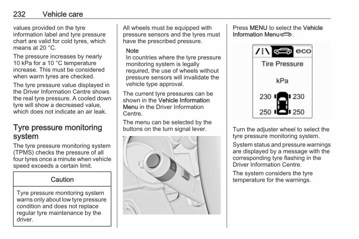
232 Vehicle care
values provided on the tyreinformation label and tyre pressurechart are valid for cold tyres, whichmeans at 20 °C.The pressure increases by nearly10 kPa for a 10 °C temperatureincrease. This must be consideredwhen warm tyres are checked.The tyre pressure value displayed inthe Driver Information Centre showsthe real tyre pressure. A cooled downtyre will show a decreased value,which does not indicate an air leak.
Tyre pressure monitoringsystemThe tyre pressure monitoring system(TPMS) checks the pressure of allfour tyres once a minute when vehiclespeed exceeds a certain limit.
Caution
Tyre pressure monitoring systemwarns only about low tyre pressurecondition and does not replaceregular tyre maintenance by thedriver.
All wheels must be equipped withpressure sensors and the tyres musthave the prescribed pressure.NoteIn countries where the tyre pressuremonitoring system is legallyrequired, the use of wheels withoutpressure sensors will invalidate thevehicle type approval.
The current tyre pressures can beshown in the Vehicle InformationMenu in the Driver InformationCentre.The menu can be selected by thebuttons on the turn signal lever.
Press MENU to select the VehicleInformation MenuX.
Turn the adjuster wheel to select thetyre pressure monitoring system.System status and pressure warningsare displayed by a message with thecorresponding tyre flashing in theDriver Information Centre.The system considers the tyretemperature for the warnings.

Vehicle care 233
A detected low tyre pressurecondition is indicated by illuminationof control indicator w 3 91.If w illuminates, stop as soon aspossible and inflate the tyres asrecommended 3 271.If w flashes for 60-90 seconds andthen illuminates continuously, there isa fault in the system. Consult aworkshop.After inflating, driving may berequired to update the tyre pressurevalues in the Driver InformationCentre. During this time w mayilluminate.
If w illuminates at lower temperaturesand extinguishes after some driving,this could be an indicator forapproaching a low tyre pressurecondition. Check tyre pressure.Vehicle messages 3 99.If the tyre pressure must be reducedor increased, switch off ignition.Only mount wheels with pressuresensors, otherwise the tyre pressurewill not be displayed and willuminates continuously.A spare wheel or temporary sparewheel is not equipped with pressuresensors. The tyre pressuremonitoring system is not operationalfor these wheels. Control indicator willuminates. For the further threewheels the system remainsoperational.The use of commercially availableliquid tyre repair kits can impair thefunction of the system. Factory-approved repair kits can be used.Operating electronic devices or beingclose to facilities using similar wavefrequencies could disrupt the tyrepressure monitoring system.
Each time the tyres are replaced, tyrepressure monitoring system sensorsmust be dismounted and serviced.For the screwed sensor: replacevalve core and sealing ring. Forclipped sensor: replace completevalve stem.
Vehicle loading statusAdjust tyre pressure to load conditionaccording to the tyre information labelor tyre pressure chart 3 271, andselect the appropriate setting in theTyre load menu in the DriverInformation Centre 3 93. This settingis the reference for the tyre pressurewarnings.The Tyre Load menu only appears ifthe vehicle is in a standstill and theparking brake is applied. On vehicleswith automatic transmission, theselector lever must be in P.
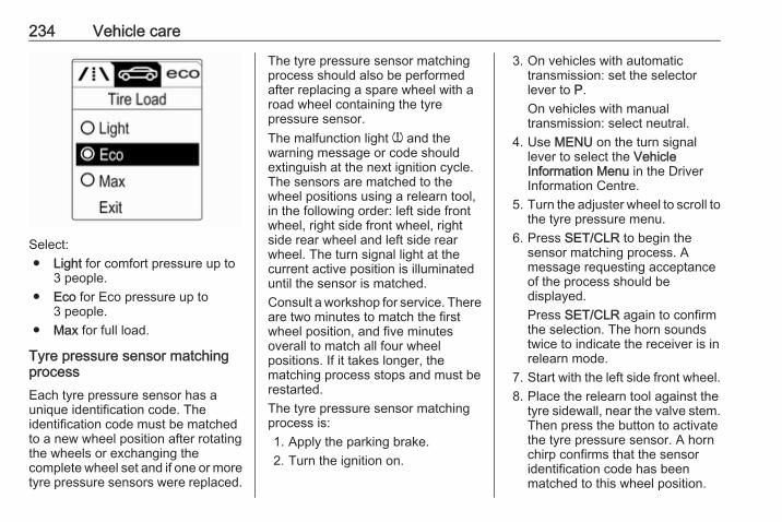
234 Vehicle care
Select:● Light for comfort pressure up to
3 people.● Eco for Eco pressure up to
3 people.● Max for full load.
Tyre pressure sensor matchingprocessEach tyre pressure sensor has aunique identification code. Theidentification code must be matchedto a new wheel position after rotatingthe wheels or exchanging thecomplete wheel set and if one or moretyre pressure sensors were replaced.
The tyre pressure sensor matchingprocess should also be performedafter replacing a spare wheel with aroad wheel containing the tyrepressure sensor.The malfunction light w and thewarning message or code shouldextinguish at the next ignition cycle.The sensors are matched to thewheel positions using a relearn tool,in the following order: left side frontwheel, right side front wheel, rightside rear wheel and left side rearwheel. The turn signal light at thecurrent active position is illuminateduntil the sensor is matched.Consult a workshop for service. Thereare two minutes to match the firstwheel position, and five minutesoverall to match all four wheelpositions. If it takes longer, thematching process stops and must berestarted.The tyre pressure sensor matchingprocess is:1. Apply the parking brake.2. Turn the ignition on.
3. On vehicles with automatictransmission: set the selectorlever to P.On vehicles with manualtransmission: select neutral.
4. Use MENU on the turn signallever to select the VehicleInformation Menu in the DriverInformation Centre.
5. Turn the adjuster wheel to scroll tothe tyre pressure menu.
6. Press SET/CLR to begin thesensor matching process. Amessage requesting acceptanceof the process should bedisplayed.Press SET/CLR again to confirmthe selection. The horn soundstwice to indicate the receiver is inrelearn mode.
7. Start with the left side front wheel.8. Place the relearn tool against the
tyre sidewall, near the valve stem.Then press the button to activatethe tyre pressure sensor. A hornchirp confirms that the sensoridentification code has beenmatched to this wheel position.

Vehicle care 235
9. Proceed to the right side frontwheel, and repeat the procedurein Step 8.
10. Proceed to the right side rearwheel, and repeat the procedurein Step 8.
11. Proceed to the left side rearwheel, and repeat the procedurein Step 8. The horn sounds twiceto indicate the sensoridentification code has beenmatched to the left side rear tyre,and the tyre pressure sensormatching process is no longeractive.
12. Turn off the ignition.13. Set all four tyres to the
recommended air pressure levelas indicated on the tyre pressurelabel.
14. Ensure the tyre loading status isset according to the selectedpressure 3 93.
Tread depthCheck tread depth at regularintervals.
Tyres should be replaced for safetyreasons at a tread depth of 2-3 mm(4 mm for winter tyres).For safety reasons it is recommendedthat the tread depth of the tyres onone axle should not vary by more than2 mm.
The legally permissible minimumtread depth (1.6 mm) has beenreached when the tread has worndown as far as one of the tread wearindicators (TWI). Their position isindicated by markings on thesidewall.
If there is more wear at the front thanthe rear, swap round front wheels andrear wheels periodically. Ensure thatthe direction of rotation of the wheelsis the same as before.Tyres age, even if they are not used.We recommend tyre replacementevery 6 years.
Changing tyre and wheelsizeIf tyres of a different size than thosefitted at the factory are used, it may benecessary to reprogramme thespeedometer as well as the nominaltyre pressure and make other vehiclemodifications.After converting to a different tyresize, have the label with tyrepressures replaced.
9 Warning
Use of unsuitable tyres or wheelsmay lead to accidents and willinvalidate the vehicle typeapproval.
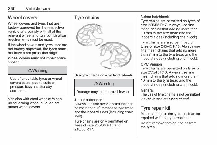
236 Vehicle care
Wheel coversWheel covers and tyres that arefactory approved for the respectivevehicle and comply with all of therelevant wheel and tyre combinationrequirements must be used.If the wheel covers and tyres used arenot factory approved, the tyres mustnot have a rim protection ridge.Wheel covers must not impair brakecooling.
9 Warning
Use of unsuitable tyres or wheelcovers could lead to suddenpressure loss and therebyaccidents.
Vehicles with steel wheels: Whenusing locking wheel nuts, do notattach wheel covers.
Tyre chains
Use tyre chains only on front wheels.
9 Warning
Damage may lead to tyre blowout.
4-door notchbackAlways use fine mesh chains that addno more than 10 mm to the tyre treadand the inboard sides (including chainlock).Tyre chains are only permitted ontyres of size 205/60 R16 and215/50 R17.
3-door hatchbackTyre chains are permitted on tyres ofsize 225/55 R17. Always use finemesh chains that add no more than10 mm to the tyre tread and theinboard sides (including chain lock).Tyre chains are also permitted ontyres of size 245/45 R18. Always usefine mesh chains that add no morethan 7 mm to the tyre tread and theinboard sides (including chain lock).OPC VersionTyre chains are permitted on tyres ofsize 235/45 R18. Always use finemesh chains that add no more than10 mm to the tyre tread and theinboard sides (including chain lock).GeneralThe use of tyre chains is not permittedon the temporary spare wheel.
Tyre repair kitMinor damage to the tyre tread can berepaired with the tyre repair kit.Do not remove foreign bodies fromthe tyres.
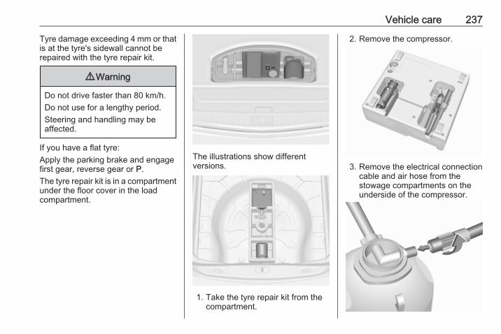
Vehicle care 237
Tyre damage exceeding 4 mm or thatis at the tyre's sidewall cannot berepaired with the tyre repair kit.
9 Warning
Do not drive faster than 80 km/h.Do not use for a lengthy period.Steering and handling may beaffected.
If you have a flat tyre:Apply the parking brake and engagefirst gear, reverse gear or P.The tyre repair kit is in a compartmentunder the floor cover in the loadcompartment.
The illustrations show differentversions.
1. Take the tyre repair kit from thecompartment.
2. Remove the compressor.
3. Remove the electrical connectioncable and air hose from thestowage compartments on theunderside of the compressor.
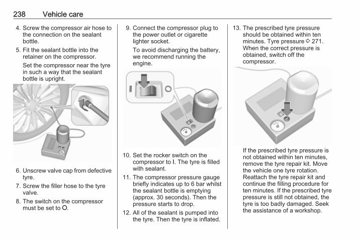
238 Vehicle care
4. Screw the compressor air hose tothe connection on the sealantbottle.
5. Fit the sealant bottle into theretainer on the compressor.Set the compressor near the tyrein such a way that the sealantbottle is upright.
6. Unscrew valve cap from defectivetyre.
7. Screw the filler hose to the tyrevalve.
8. The switch on the compressormust be set to J.
9. Connect the compressor plug tothe power outlet or cigarettelighter socket.To avoid discharging the battery,we recommend running theengine.
10. Set the rocker switch on thecompressor to I. The tyre is filledwith sealant.
11. The compressor pressure gaugebriefly indicates up to 6 bar whilstthe sealant bottle is emptying(approx. 30 seconds). Then thepressure starts to drop.
12. All of the sealant is pumped intothe tyre. Then the tyre is inflated.
13. The prescribed tyre pressureshould be obtained within tenminutes. Tyre pressure 3 271.When the correct pressure isobtained, switch off thecompressor.
If the prescribed tyre pressure isnot obtained within ten minutes,remove the tyre repair kit. Movethe vehicle one tyre rotation.Reattach the tyre repair kit andcontinue the filling procedure forten minutes. If the prescribed tyrepressure is still not obtained, thetyre is too badly damaged. Seekthe assistance of a workshop.
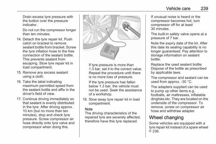
Vehicle care 239
Drain excess tyre pressure withthe button over the pressureindicator.Do not run the compressor longerthan ten minutes.
14. Detach the tyre repair kit. Pushcatch on bracket to removesealant bottle from bracket. Screwthe tyre inflation hose to the freeconnection of the sealant bottle.This prevents sealant fromescaping. Stow tyre repair kit inload compartment.
15. Remove any excess sealantusing a cloth.
16. Take the label indicatingmaximum permitted speed fromthe sealant bottle and affix in thedriver's field of view.
17. Continue driving immediately sothat sealant is evenly distributedin the tyre. After driving approx.10 km (but no more than tenminutes), stop and check tyrepressure. Screw compressor airhose directly onto tyre valve andcompressor when doing this.
If tyre pressure is more than1.3 bar, set it to the correct value.Repeat the procedure until thereis no more loss of pressure.If the tyre pressure has fallenbelow 1.3 bar, the vehicle mustnot be used. Seek the assistanceof a workshop.
18. Stow away tyre repair kit in loadcompartment.
NoteThe driving characteristics of therepaired tyre are severely affected,therefore have this tyre replaced.
If unusual noise is heard or thecompressor becomes hot, turncompressor off for at least30 minutes.The built-in safety valve opens at apressure of 7 bar.Note the expiry date of the kit. Afterthis date its sealing capability is nolonger guaranteed. Pay attention tostorage information on sealantbottle.Replace the used sealant bottle.Dispose of the bottle as prescribedby applicable laws.The compressor and sealant can beused from approx. -30 °C.The adapters supplied can be usedto pump up other items e.g.footballs, air mattresses, inflatabledinghies etc. They are located on theunderside of the compressor. Toremove, screw on compressor airhose and withdraw adapter.
Wheel changingSome vehicles are equipped with atyre repair kit instead of a spare wheel3 236.
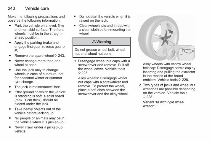
240 Vehicle care
Make the following preparations andobserve the following information:● Park the vehicle on a level, firm
and non-skid surface. The frontwheels must be in the straight-ahead position.
● Apply the parking brake andengage first gear, reverse gear orP.
● Remove the spare wheel 3 243.● Never change more than one
wheel at once.● Use the jack only to change
wheels in case of puncture, notfor seasonal winter or summertyre change.
● The jack is maintenance-free.● If the ground on which the vehicle
is standing is soft, a solid board(max. 1 cm thick) should beplaced under the jack.
● Take heavy objects out of thevehicle before jacking up.
● No people or animals may be inthe vehicle when it is jacked-up.
● Never crawl under a jacked-upvehicle.
● Do not start the vehicle when it israised on the jack.
● Clean wheel nuts and thread witha clean cloth before mounting thewheel.
9 Warning
Do not grease wheel bolt, wheelnut and wheel nut cone.
1. Disengage wheel nut caps with ascrewdriver and remove. Pull offthe wheel cover. Vehicle tools3 228.Alloy wheels: Disengage wheelnut caps with a screwdriver andremove. To protect the wheel,place a soft cloth between thescrewdriver and the alloy wheel.
Alloy wheels with centre wheelbolt cap: Disengage centre cap byinserting and pulling the extractorin the recess of the brandemblem. Vehicle tools 3 228.
2. Two types of jacks and wheel nutwrenches are possible dependingon the version. Vehicle tools3 228.Variant 1a with rigid wheelwrench:
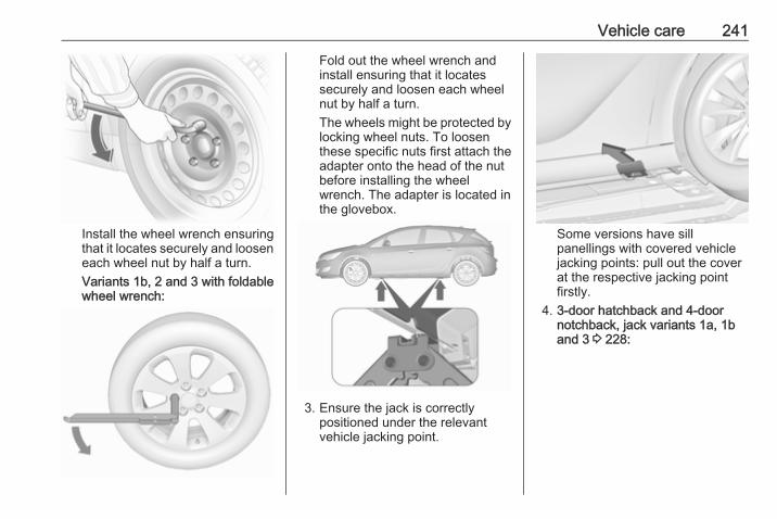
Vehicle care 241
Install the wheel wrench ensuringthat it locates securely and looseneach wheel nut by half a turn.Variants 1b, 2 and 3 with foldablewheel wrench:
Fold out the wheel wrench andinstall ensuring that it locatessecurely and loosen each wheelnut by half a turn.The wheels might be protected bylocking wheel nuts. To loosenthese specific nuts first attach theadapter onto the head of the nutbefore installing the wheelwrench. The adapter is located inthe glovebox.
3. Ensure the jack is correctlypositioned under the relevantvehicle jacking point.
Some versions have sillpanellings with covered vehiclejacking points: pull out the coverat the respective jacking pointfirstly.
4. 3-door hatchback and 4-doornotchback, jack variants 1a, 1band 3 3 228:
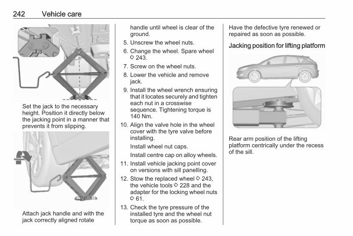
242 Vehicle care
Set the jack to the necessaryheight. Position it directly belowthe jacking point in a manner thatprevents it from slipping.
Attach jack handle and with thejack correctly aligned rotate
handle until wheel is clear of theground.
5. Unscrew the wheel nuts.6. Change the wheel. Spare wheel
3 243.7. Screw on the wheel nuts.8. Lower the vehicle and remove
jack.9. Install the wheel wrench ensuring
that it locates securely and tighteneach nut in a crosswisesequence. Tightening torque is140 Nm.
10. Align the valve hole in the wheelcover with the tyre valve beforeinstalling.Install wheel nut caps.Install centre cap on alloy wheels.
11. Install vehicle jacking point coveron versions with sill panelling.
12. Stow the replaced wheel 3 243,the vehicle tools 3 228 and theadapter for the locking wheel nuts3 61.
13. Check the tyre pressure of theinstalled tyre and the wheel nuttorque as soon as possible.
Have the defective tyre renewed orrepaired as soon as possible.
Jacking position for lifting platform
Rear arm position of the liftingplatform centrically under the recessof the sill.
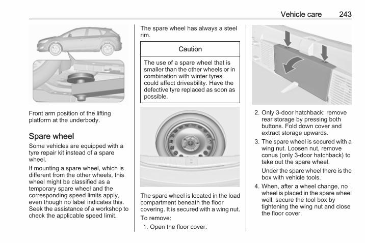
Vehicle care 243
Front arm position of the liftingplatform at the underbody.
Spare wheelSome vehicles are equipped with atyre repair kit instead of a sparewheel.If mounting a spare wheel, which isdifferent from the other wheels, thiswheel might be classified as atemporary spare wheel and thecorresponding speed limits apply,even though no label indicates this.Seek the assistance of a workshop tocheck the applicable speed limit.
The spare wheel has always a steelrim.
Caution
The use of a spare wheel that issmaller than the other wheels or incombination with winter tyrescould affect driveability. Have thedefective tyre replaced as soon aspossible.
The spare wheel is located in the loadcompartment beneath the floorcovering. It is secured with a wing nut.To remove:1. Open the floor cover.
2. Only 3-door hatchback: removerear storage by pressing bothbuttons. Fold down cover andextract storage upwards.
3. The spare wheel is secured with awing nut. Loosen nut, removeconus (only 3-door hatchback) totake out the spare wheel.Under the spare wheel there is thebox with vehicle tools.
4. When, after a wheel change, nowheel is placed in the spare wheelwell, secure the tool box bytightening the wing nut and closethe floor cover.
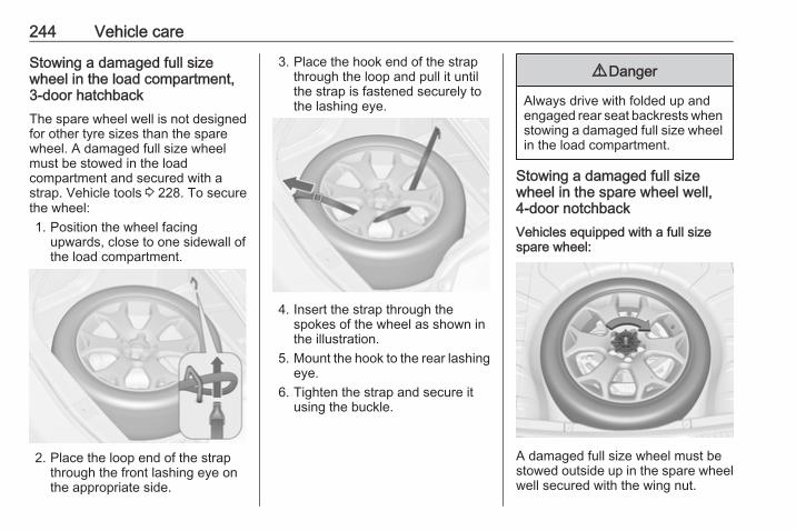
244 Vehicle care
Stowing a damaged full sizewheel in the load compartment,3-door hatchbackThe spare wheel well is not designedfor other tyre sizes than the sparewheel. A damaged full size wheelmust be stowed in the loadcompartment and secured with astrap. Vehicle tools 3 228. To securethe wheel:1. Position the wheel facing
upwards, close to one sidewall ofthe load compartment.
2. Place the loop end of the strapthrough the front lashing eye onthe appropriate side.
3. Place the hook end of the strapthrough the loop and pull it untilthe strap is fastened securely tothe lashing eye.
4. Insert the strap through thespokes of the wheel as shown inthe illustration.
5. Mount the hook to the rear lashingeye.
6. Tighten the strap and secure itusing the buckle.
9 Danger
Always drive with folded up andengaged rear seat backrests whenstowing a damaged full size wheelin the load compartment.
Stowing a damaged full sizewheel in the spare wheel well,4-door notchbackVehicles equipped with a full sizespare wheel:
A damaged full size wheel must bestowed outside up in the spare wheelwell secured with the wing nut.
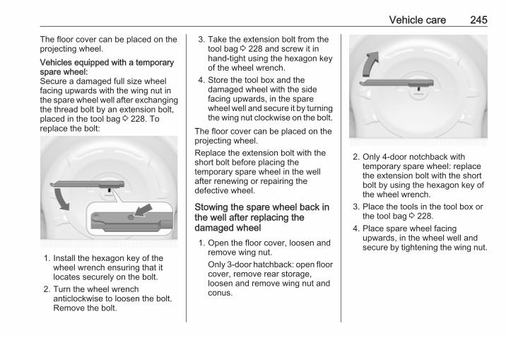
Vehicle care 245
The floor cover can be placed on theprojecting wheel.Vehicles equipped with a temporaryspare wheel:Secure a damaged full size wheelfacing upwards with the wing nut inthe spare wheel well after exchangingthe thread bolt by an extension bolt,placed in the tool bag 3 228. Toreplace the bolt:
1. Install the hexagon key of thewheel wrench ensuring that itlocates securely on the bolt.
2. Turn the wheel wrenchanticlockwise to loosen the bolt.Remove the bolt.
3. Take the extension bolt from thetool bag 3 228 and screw it inhand-tight using the hexagon keyof the wheel wrench.
4. Store the tool box and thedamaged wheel with the sidefacing upwards, in the sparewheel well and secure it by turningthe wing nut clockwise on the bolt.
The floor cover can be placed on theprojecting wheel.Replace the extension bolt with theshort bolt before placing thetemporary spare wheel in the wellafter renewing or repairing thedefective wheel.
Stowing the spare wheel back inthe well after replacing thedamaged wheel1. Open the floor cover, loosen and
remove wing nut.Only 3-door hatchback: open floorcover, remove rear storage,loosen and remove wing nut andconus.
2. Only 4-door notchback withtemporary spare wheel: replacethe extension bolt with the shortbolt by using the hexagon key ofthe wheel wrench.
3. Place the tools in the tool box orthe tool bag 3 228.
4. Place spare wheel facingupwards, in the wheel well andsecure by tightening the wing nut.
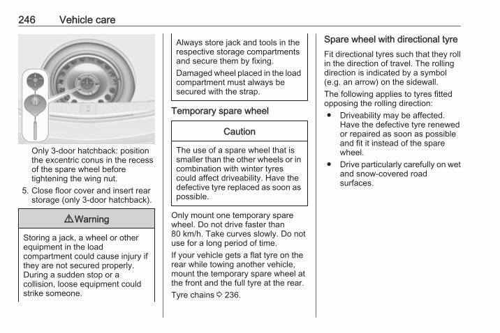
246 Vehicle care
Only 3-door hatchback: positionthe excentric conus in the recessof the spare wheel beforetightening the wing nut.
5. Close floor cover and insert rearstorage (only 3-door hatchback).
9 Warning
Storing a jack, a wheel or otherequipment in the loadcompartment could cause injury ifthey are not secured properly.During a sudden stop or acollision, loose equipment couldstrike someone.
Always store jack and tools in therespective storage compartmentsand secure them by fixing.Damaged wheel placed in the loadcompartment must always besecured with the strap.
Temporary spare wheel
Caution
The use of a spare wheel that issmaller than the other wheels or incombination with winter tyrescould affect driveability. Have thedefective tyre replaced as soon aspossible.
Only mount one temporary sparewheel. Do not drive faster than80 km/h. Take curves slowly. Do notuse for a long period of time.If your vehicle gets a flat tyre on therear while towing another vehicle,mount the temporary spare wheel atthe front and the full tyre at the rear.Tyre chains 3 236.
Spare wheel with directional tyreFit directional tyres such that they rollin the direction of travel. The rollingdirection is indicated by a symbol(e.g. an arrow) on the sidewall.The following applies to tyres fittedopposing the rolling direction:● Driveability may be affected.
Have the defective tyre renewedor repaired as soon as possibleand fit it instead of the sparewheel.
● Drive particularly carefully on wetand snow-covered roadsurfaces.

Vehicle care 247
Jump startingDo not start with quick charger.A vehicle with a discharged vehiclebattery can be started using jumpleads and the vehicle battery ofanother vehicle.
9 Warning
Be extremely careful when startingwith jump leads. Any deviationfrom the following instructions canlead to injuries or damage causedby battery explosion or damage tothe electrical systems of bothvehicles.
9 Warning
Avoid contact of the battery witheyes, skin, fabrics and paintedsurfaces. The fluid containssulphuric acid which can causeinjuries and damage in the eventof direct contact.
● Never expose the vehicle batteryto naked flames or sparks.
● A discharged vehicle battery canalready freeze at a temperatureof 0 °C. Defrost the frozen vehiclebattery before connecting jumpleads.
● Wear eye protection andprotective clothing whenhandling a vehicle battery.
● Use a booster vehicle batterywith the same voltage (12 Volts).Its capacity (Ah) must not bemuch less than that of thedischarged vehicle battery.
● Use jump leads with insulatedterminals and a cross section ofat least 16 mm2 (25 mm2 fordiesel engines).
● Do not disconnect the dischargedvehicle battery from the vehicle.
● Switch off all unnecessaryelectrical consumers.
● Do not lean over the vehiclebattery during jump starting.
● Do not allow the terminals of onelead to touch those of the otherlead.
● The vehicles must not come intocontact with each other duringthe jump starting process.
● Apply the parking brake,transmission in neutral,automatic transmission in P.
● Open the positive terminalprotection caps of both vehiclebatteries.
Lead connection order:1. Connect the red lead to the
positive terminal of the boostervehicle battery.
2. Connect the other end of the redlead to the positive terminal of thedischarged vehicle battery.
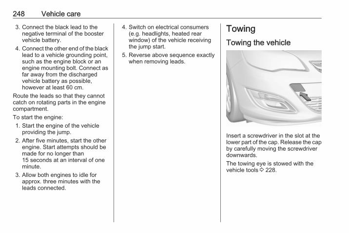
248 Vehicle care
3. Connect the black lead to thenegative terminal of the boostervehicle battery.
4. Connect the other end of the blacklead to a vehicle grounding point,such as the engine block or anengine mounting bolt. Connect asfar away from the dischargedvehicle battery as possible,however at least 60 cm.
Route the leads so that they cannotcatch on rotating parts in the enginecompartment.To start the engine:1. Start the engine of the vehicle
providing the jump.2. After five minutes, start the other
engine. Start attempts should bemade for no longer than15 seconds at an interval of oneminute.
3. Allow both engines to idle forapprox. three minutes with theleads connected.
4. Switch on electrical consumers(e.g. headlights, heated rearwindow) of the vehicle receivingthe jump start.
5. Reverse above sequence exactlywhen removing leads.
TowingTowing the vehicle
Insert a screwdriver in the slot at thelower part of the cap. Release the capby carefully moving the screwdriverdownwards.The towing eye is stowed with thevehicle tools 3 228.
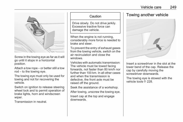
Vehicle care 249
Screw in the towing eye as far as it willgo until it stops in a horizontalposition.Attach a tow rope – or better still a towrod – to the towing eye.The towing eye must only be used fortowing and not for recovering thevehicle.Switch on ignition to release steeringwheel lock and to permit operation ofbrake lights, horn and windscreenwiper.Transmission in neutral.
Caution
Drive slowly. Do not drive jerkily.Excessive tractive force candamage the vehicle.
When the engine is not running,considerably more force is needed tobrake and steer.To prevent the entry of exhaust gasesfrom the towing vehicle, switch on theair recirculation and close thewindows.Vehicles with automatic transmission:The vehicle must be towed facingforwards, not faster than 80 km/h norfurther than 100 km. In all other casesand when the transmission isdefective, the front axle must beraised off the ground.Seek the assistance of a workshop.After towing, unscrew the towing eye.Insert cap at the top and engagedownwards.
Towing another vehicle
Insert a screwdriver in the slot at thelower bend of the cap. Release thecap by carefully moving thescrewdriver downwards.The towing eye is stowed with thevehicle tools 3 228.
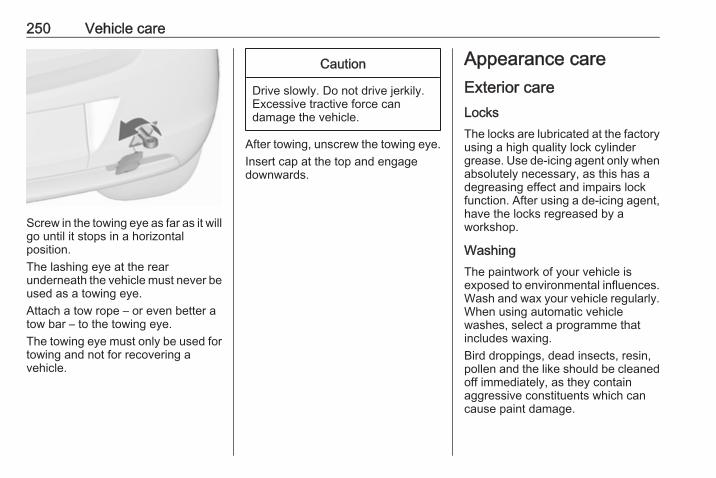
250 Vehicle care
Screw in the towing eye as far as it willgo until it stops in a horizontalposition.The lashing eye at the rearunderneath the vehicle must never beused as a towing eye.Attach a tow rope – or even better atow bar – to the towing eye.The towing eye must only be used fortowing and not for recovering avehicle.
Caution
Drive slowly. Do not drive jerkily.Excessive tractive force candamage the vehicle.
After towing, unscrew the towing eye.Insert cap at the top and engagedownwards.
Appearance careExterior careLocksThe locks are lubricated at the factoryusing a high quality lock cylindergrease. Use de-icing agent only whenabsolutely necessary, as this has adegreasing effect and impairs lockfunction. After using a de-icing agent,have the locks regreased by aworkshop.
WashingThe paintwork of your vehicle isexposed to environmental influences.Wash and wax your vehicle regularly.When using automatic vehiclewashes, select a programme thatincludes waxing.Bird droppings, dead insects, resin,pollen and the like should be cleanedoff immediately, as they containaggressive constituents which cancause paint damage.
Vehicle care 251
If using a vehicle wash, comply withthe vehicle wash manufacturer'sinstructions. The windscreen wiperand rear window wiper must beswitched off. Remove antenna andexternal accessories such as roofracks etc.If you wash your vehicle by hand,make sure that the insides of thewheel housings are also thoroughlyrinsed out.Clean edges and folds on openeddoors and the bonnet as well as theareas they cover.Clean bright metal mouldings with acleaning solution approved foraluminium to avoid damages.
Caution
Always use a cleaning agent witha pH value of four to nine.Do not use cleaning agents on hotsurfaces.
Have the door hinges of all doorsgreased by a workshop.
Do not clean the engine compartmentwith a steam-jet or high-pressure jetcleaner.On vehicles with emblem touchpad:when cleaning with a high-pressurejet cleaner ensure a minimumdistance of 30 cm when workingaround the tailgate to preventunintended unlocking.Thoroughly rinse and leather-off thevehicle. Rinse leather frequently. Useseparate leathers for painted andglass surfaces: remnants of wax onthe windows will impair vision.Do not use hard objects to removespots of tar. Use tar removal spray onpainted surfaces.
Exterior lightsHeadlight and other light covers aremade of plastic. Do not use anyabrasive or caustic agents, do not usean ice scraper, and do not clean themdry.
Polishing and waxingWax the vehicle regularly (at thelatest when water no longer beads).Otherwise, the paintwork will dry out.Polishing is necessary only if the painthas become dull or if solid depositshave become attached to it.Paintwork polish with silicone forms aprotective film, making waxingunnecessary.Plastic body parts must not be treatedwith wax or polishing agents.
Windows and windscreen wiperbladesUse a soft lint-free cloth or chamoisleather together with window cleanerand insect remover.When cleaning the rear window frominside, always wipe in parallel to theheating element to prevent damage.For mechanical removal of ice, use asharp-edged ice scraper. Press thescraper firmly against the glass sothat no dirt can get under it andscratch the glass.
252 Vehicle care
Remove dirt residues from smearingwiper blades by using a soft cloth andwindow cleaner. Also make sure toremove any residues such as wax,insect residues and similar from thewindow.Ice residues, pollution and continuouswiping on dry windows will damage oreven destroy the wiper blades.
SunroofNever clean with solvents or abrasiveagents, fuels, aggressive media(e.g. paint cleaner, acetone-containing solutions etc.), acidic orhighly alkaline media or abrasivepads. Do not apply wax or polishingagents to the sunroof.
Glass panelNever clean with solvents or abrasiveagents, fuels, aggressive media(e.g. paint cleaner, acetone-containing solutions etc.), acidic orhighly alkaline media or abrasivepads. Do not apply wax or polishingagents to the glass panel.
Wheels and tyresDo not use high-pressure jetcleaners.Clean rims with a pH-neutral wheelcleaner.Rims are painted and can be treatedwith the same agents as the body.
Paintwork damageRectify minor paintwork damage witha touch-up pen before rust forms.Have more extensive damage or rustareas repaired by a workshop.
UnderbodySome areas of the vehicle underbodyhave a PVC undercoating while othercritical areas have a durableprotective wax coating.After the underbody is washed, checkthe underbody and have it waxed ifnecessary.Bitumen/rubber materials coulddamage the PVC coating. Haveunderbody work carried out by aworkshop.
Before and after winter, wash theunderbody and have the protectivewax coating checked.
Liquid gas system
9 Danger
Liquid gas is heavier than air andcan collect in sink points.Take care when performing workat the underbody in a pit.
For painting work and when using adrying booth at a temperature above60 °C, the liquid gas tank must beremoved.Do not make any modifications to theliquid gas system.
Towing equipmentDo not clean the coupling ball bar witha steam-jet or high-pressure jetcleaner.
Air shutterClean the shutter system in the frontbumper to maintain correctfunctionality.
Vehicle care 253
Interior careInterior and upholsteryOnly clean the vehicle interior,including the instrument panel fasciaand panelling, with a dry cloth orinterior cleaner.Clean the leather upholstery withclear water and a soft cloth. In case ofheavy soiling, use leather care.The instrument cluster and thedisplays should only be cleaned usinga soft damp cloth. If necessary use aweak soap solution.Clean fabric upholstery with avacuum cleaner and brush. Removestains with an upholstery cleaner.Clothing fabrics may not becolourfast. This could cause visiblediscolourations, especially on light-coloured upholstery. Removablestains and discolourations should becleaned as soon as possible.Clean seat belts with lukewarm wateror interior cleaner.
Caution
Close Velcro fasteners as openVelcro fasteners on clothing coulddamage seat upholstery.The same applies to clothing withsharp-edged objects, like zips orbelts or studded jeans.
Plastic and rubber partsPlastic and rubber parts can becleaned with the same cleaner asused to clean the body. Use interiorcleaner if necessary. Do not use anyother agent. Avoid solvents and petrolin particular. Do not use high-pressure jet cleaners.
254 Service and maintenance
Service andmaintenance
General information ................... 254Service information .................. 254
Recommended fluids, lubricantsand parts .................................... 255
Recommended fluids andlubricants ................................ 255
General informationService informationIn order to ensure economical andsafe vehicle operation and tomaintain the value of your vehicle, itis of vital importance that allmaintenance work is carried out at theproper intervals as specified.The detailed, up-to-date serviceschedule for your vehicle is availableat the workshop.Service display 3 83.
European service intervalsMaintenance of your vehicle isrequired every 30,000 km or after1 year, whichever occurs first, unlessotherwise indicated in the servicedisplay.A shorter service interval can be validfor severe driving behaviour, e.g. fortaxis and police vehicles.The European service intervals arevalid for the following countries:
Andorra, Austria, Belgium, Bosnia-Herzegovina, Bulgaria, Croatia,Cyprus, Czech Republic, Denmark,Estonia, Finland, France, Germany,Greece, Greenland, Hungary,Iceland, Ireland, Italy, Latvia,Liechtenstein, Lithuania,Luxembourg, Macedonia, Malta,Monaco, Montenegro, Netherlands,Norway, Poland, Portugal, Romania,San Marino, Serbia, Slovakia,Slovenia, Spain, Sweden,Switzerland, United Kingdom.Service display 3 83.
International service intervalsMaintenance of your vehicle isrequired every 15,000 km or after1 year, whichever occurs first, unlessotherwise indicated in the servicedisplay.A shorter service interval can be validfor severe driving behaviour. Severeoperating conditions exist if one ormore of the following circumstancesoccur frequently: Cold starting, stopand go operation, trailer operation,mountain driving, driving on poor andsandy road surfaces, increased air
Service and maintenance 255
pollution, presence of airborne sandand high dust content, driving at highaltitude and large variations oftemperature. Under these severeoperating conditions, certain servicework may be required more frequentlythan the regular service interval.The international service intervals arevalid for the countries which are notlisted in the European serviceintervals.Service display 3 83.
ConfirmationsConfirmation of service is recorded inthe Service and Warranty Booklet.The date and mileage is completedwith the stamp and signature of theservicing workshop.Make sure that the Service andWarranty Booklet is completedcorrectly as continuous proof ofservice is essential if any warranty orgoodwill claims are to be met, and isalso a benefit when selling thevehicle.
Service interval with remainingengine oil life durationThe service interval is based onseveral parameters depending onusage.The service display lets you knowwhen to change the engine oil.Service display 3 83.
Recommended fluids,lubricants and partsRecommended fluids andlubricantsOnly use products that meet therecommended specifications.
9 Warning
Operating materials arehazardous and could bepoisonous. Handle with care. Payattention to information given onthe containers.
Engine oilEngine oil is identified by its qualityand its viscosity. Quality is moreimportant than viscosity whenselecting which engine oil to use. Theoil quality ensures e.g. enginecleanliness, wear protection and oilaging control, whereas viscositygrade gives information on the oil'sthickness over a temperature range.
256 Service and maintenance
Dexos is the newest engine oil qualitythat provides optimum protection forpetrol and diesel engines. If it isunavailable, engine oils of other listedqualities must be used.Recommendations for petrol enginesare also valid for Compressed NaturalGas (CNG), Liquified Petroleum Gas(LPG) and Ethanol (E85) fuelledengines.Select the appropriate engine oilbased on its quality and on theminimum ambient temperature3 259.
Topping up engine oilEngine oils of different manufacturersand brands can be mixed as long asthey comply with the required engineoil quality and viscosity.Use of engine oil with onlyACEA A1/B1 or only A5/B5 quality isprohibited, since it can cause long-term engine damage under certainoperating conditions.Select the appropriate engine oilbased on its quality and on theminimum ambient temperature3 259.
Additional engine oil additivesThe use of additional engine oiladditives could cause damage andinvalidate the warranty.
Engine oil viscosity gradesThe SAE viscosity grade givesinformation of the thickness of the oil.Multigrade oil is indicated by twofigures, e.g. SAE 5W-30. The firstfigure, followed by a W, indicates thelow temperature viscosity and thesecond figure the high temperatureviscosity.Select the appropriate viscosity gradedepending on the minimum ambienttemperature 3 259.All of the recommended viscositygrades are suitable for high ambienttemperatures.
Coolant and antifreezeUse only organic acid type-long lifecoolant (LLC) antifreeze approved forthe vehicle. Consult a workshop.The system is factory filled withcoolant designed for excellentcorrosion protection and frostprotection down to approx. -28 °C. In
cold regions with very lowtemperatures, the factory filledcoolant provides frost protectiondown to approx. -37 °C. Thisconcentration should be maintainedall year round. The use of additionalcoolant additives that intend to giveadditional corrosion protection or sealagainst minor leaks can causefunction problems. Liability forconsequences resulting from the useof additional coolant additives will berejected.
Washer fluidUse only washer fluid approved forthe vehicle to prevent damage ofwiper blades, paintwork, plastic andrubber parts. Consult a workshop.
Brake and clutch fluidOver time, brake fluid absorbsmoisture which will reduce brakingeffectiveness. The brake fluid shouldtherefore be replaced at the specifiedinterval.
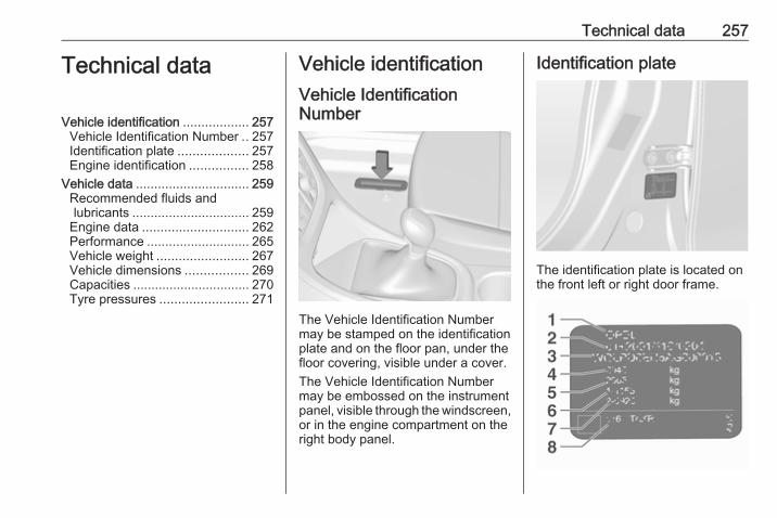
Technical data 257
Technical data
Vehicle identification .................. 257Vehicle Identification Number .. 257Identification plate ................... 257Engine identification ................ 258
Vehicle data ............................... 259Recommended fluids andlubricants ................................ 259
Engine data ............................. 262Performance ............................ 265Vehicle weight ......................... 267Vehicle dimensions ................. 269Capacities ................................ 270Tyre pressures ........................ 271
Vehicle identificationVehicle IdentificationNumber
The Vehicle Identification Numbermay be stamped on the identificationplate and on the floor pan, under thefloor covering, visible under a cover.The Vehicle Identification Numbermay be embossed on the instrumentpanel, visible through the windscreen,or in the engine compartment on theright body panel.
Identification plate
The identification plate is located onthe front left or right door frame.
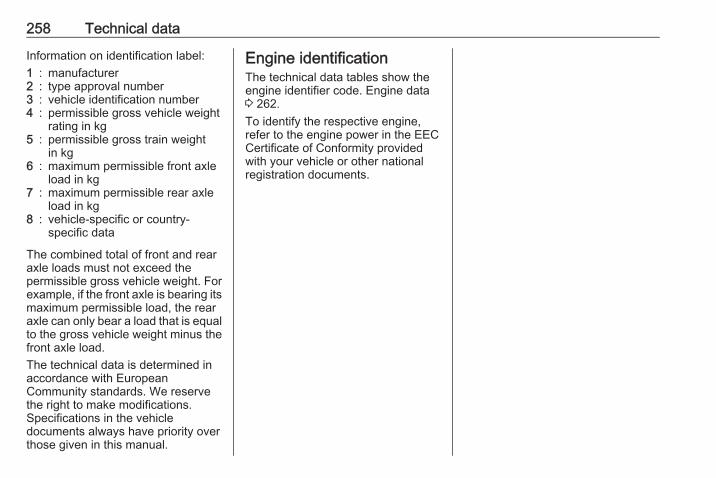
258 Technical data
Information on identification label:1 : manufacturer2 : type approval number3 : vehicle identification number4 : permissible gross vehicle weight
rating in kg5 : permissible gross train weight
in kg6 : maximum permissible front axle
load in kg7 : maximum permissible rear axle
load in kg8 : vehicle-specific or country-
specific data
The combined total of front and rearaxle loads must not exceed thepermissible gross vehicle weight. Forexample, if the front axle is bearing itsmaximum permissible load, the rearaxle can only bear a load that is equalto the gross vehicle weight minus thefront axle load.The technical data is determined inaccordance with EuropeanCommunity standards. We reservethe right to make modifications.Specifications in the vehicledocuments always have priority overthose given in this manual.
Engine identificationThe technical data tables show theengine identifier code. Engine data3 262.To identify the respective engine,refer to the engine power in the EECCertificate of Conformity providedwith your vehicle or other nationalregistration documents.
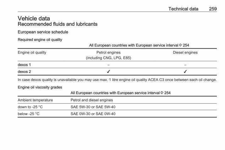
Technical data 259
Vehicle dataRecommended fluids and lubricantsEuropean service schedule
Required engine oil qualityAll European countries with European service interval 3 254
Engine oil quality Petrol engines(including CNG, LPG, E85)
Diesel engines
dexos 1 – –
dexos 2 ✔ ✔
In case dexos quality is unavailable you may use max. 1 litre engine oil quality ACEA C3 once between each oil change.
Engine oil viscosity gradesAll European countries with European service interval 3 254
Ambient temperature Petrol and diesel engines
down to -25 °C SAE 5W-30 or SAE 5W-40
below -25 °C SAE 0W-30 or SAE 0W-40
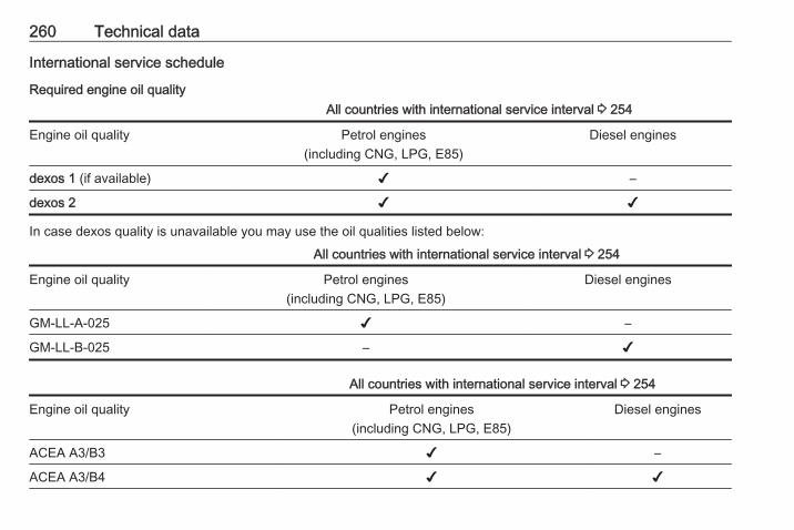
260 Technical data
International service schedule
Required engine oil qualityAll countries with international service interval 3 254
Engine oil quality Petrol engines(including CNG, LPG, E85)
Diesel engines
dexos 1 (if available) ✔ –
dexos 2 ✔ ✔
In case dexos quality is unavailable you may use the oil qualities listed below:
All countries with international service interval 3 254
Engine oil quality Petrol engines(including CNG, LPG, E85)
Diesel engines
GM-LL-A-025 ✔ –
GM-LL-B-025 – ✔
All countries with international service interval 3 254
Engine oil quality Petrol engines(including CNG, LPG, E85)
Diesel engines
ACEA A3/B3 ✔ –
ACEA A3/B4 ✔ ✔
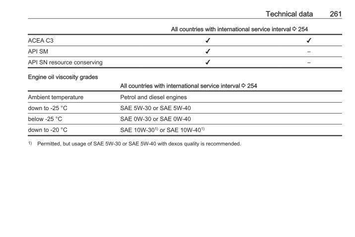
Technical data 261
All countries with international service interval 3 254
ACEA C3 ✔ ✔
API SM ✔ –
API SN resource conserving ✔ –
Engine oil viscosity gradesAll countries with international service interval 3 254
Ambient temperature Petrol and diesel engines
down to -25 °C SAE 5W-30 or SAE 5W-40
below -25 °C SAE 0W-30 or SAE 0W-40
down to -20 °C SAE 10W-301) or SAE 10W-401)
1) Permitted, but usage of SAE 5W-30 or SAE 5W-40 with dexos quality is recommended.
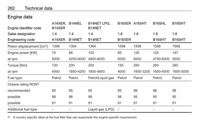
262 Technical data
Engine data
Engine identifier codeA14XER,B14XER
B14NEL B14NET LPG,B14NET
B16XER A16XHT B16SHL B16SHT
Sales designation 1.4 1.4 1.4 1.6 1.6 1.6 1.6Engineering code A14XER B14NET B14NET B16XER B16SHT B16SHT
Piston displacement [cm3] 1398 1364 1364 1598 1598 1598 1598
Engine power [kW] 74 88 103 85 125 125 147
at rpm 6000 4200-6000 4900-6000 6000 6000 4750-6000 5500
Torque [Nm] 130 200 200 155 260 260 280
at rpm 4000 1850-4200 1850-4900 4000 1650-3200 1650-4500 1650-5000
Fuel type Petrol Petrol Petrol/Liquid gas Petrol Petrol Petrol Petrol
Octane rating RON2)
recommended 95 95 95 95 98 98 98
possible 98 98 98 98 95 95 95
possible 91 91 91 91 91 91 91
Additional fuel type – – Liquid gas (LPG) – – – –
2) A country specific label at the fuel filler flap can supersede the engine specific requirement.
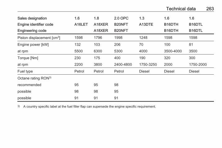
Technical data 263
Sales designation 1.6 1.8 2.0 OPC 1.3 1.6 1.6Engine identifier code A16LET A18XER B20NFT A13DTE B16DTH B16DTLEngineering code A18XER B20NFT B16DTH B16DTL
Piston displacement [cm3] 1598 1796 1998 1248 1598 1598
Engine power [kW] 132 103 206 70 100 81
at rpm 5500 6300 5300 4000 3500-4000 3500
Torque [Nm] 230 175 400 190 320 300
at rpm 2200 3800 2400-4800 1750-3250 2000 1750-2000
Fuel type Petrol Petrol Petrol Diesel Diesel Diesel
Octane rating RON3)
recommended 95 95 98
possible 98 98 95
possible 91 91 91
3) A country specific label at the fuel filler flap can supersede the engine specific requirement.
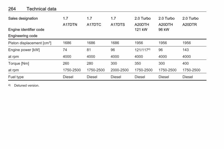
264 Technical data
Sales designation 1.7 1.7 1.7 2.0 Turbo 2.0 Turbo 2.0 Turbo
Engine identifier codeA17DTN A17DTC A17DTS A20DTH
121 kWA20DTH96 kW
A20DTR
Engineering code
Piston displacement [cm3] 1686 1686 1686 1956 1956 1956
Engine power [kW] 74 81 96 121/1174) 96 143
at rpm 4000 4000 4000 4000 4000 4000
Torque [Nm] 260 280 300 350 300 400
at rpm 1750-2500 1750-2500 2000-2500 1750-2500 1750-2500 1750-2500
Fuel type Diesel Diesel Diesel Diesel Diesel Diesel
4) Detuned version.
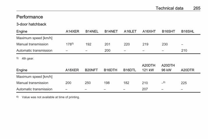
Technical data 265
Performance3-door hatchback
Engine A14XER B14NEL B14NET A16LET A16XHT B16SHT B16SHL
Maximum speed [km/h]
Manual transmission 1785) 192 201 220 219 230 –
Automatic transmission – – 200 – – – 210
5) 4th gear.
Engine A18XER B20NFT B16DTH B16DTLA20DTH121 kW
A20DTH96 kW A20DTR
Maximum speed [km/h]
Manual transmission 200 250 198 182 210 –6) 225
Automatic transmission – – – – 207 – –
6) Value was not available at time of printing.
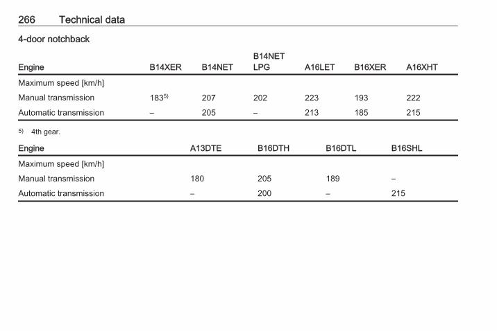
266 Technical data
4-door notchback
Engine B14XER B14NETB14NETLPG A16LET B16XER A16XHT
Maximum speed [km/h]
Manual transmission 1835) 207 202 223 193 222
Automatic transmission – 205 – 213 185 215
5) 4th gear.
Engine A13DTE B16DTH B16DTL B16SHL
Maximum speed [km/h]
Manual transmission 180 205 189 –
Automatic transmission – 200 – 215
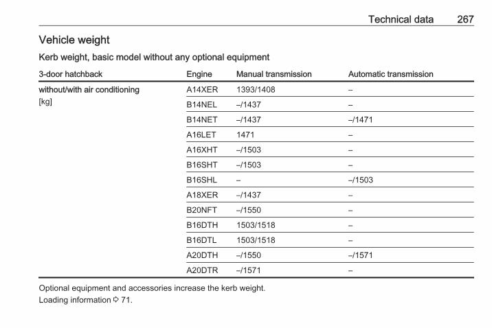
Technical data 267
Vehicle weightKerb weight, basic model without any optional equipment
3-door hatchback Engine Manual transmission Automatic transmission
without/with air conditioning[kg]
A14XER 1393/1408 –
B14NEL –/1437 –
B14NET –/1437 –/1471
A16LET 1471 –
A16XHT –/1503 –
B16SHT –/1503 –
B16SHL – –/1503
A18XER –/1437 –
B20NFT –/1550 –
B16DTH 1503/1518 –
B16DTL 1503/1518 –
A20DTH –/1550 –/1571
A20DTR –/1571 –
Optional equipment and accessories increase the kerb weight.Loading information 3 71.
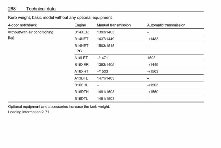
268 Technical data
Kerb weight, basic model without any optional equipment
4-door notchback Engine Manual transmission Automatic transmission
without/with air conditioning[kg]
B14XER 1393/1405 –
B14NET 1437/1449 –/1483
B14NETLPG
1503/1515 –
A16LET –/1471 1503
B16XER 1393/1405 –/1449
A16XHT –/1503 –/1503
A13DTE 1471/1483 –
B16SHL – –/1503
B16DTH 1491/1503 –/1550
B16DTL 1491/1503 –
Optional equipment and accessories increase the kerb weight.Loading information 3 71.
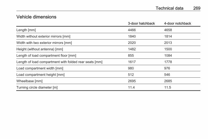
Technical data 269
Vehicle dimensions3-door hatchback 4-door notchback
Length [mm] 4466 4658
Width without exterior mirrors [mm] 1840 1814
Width with two exterior mirrors [mm] 2020 2013
Height (without antenna) [mm] 1482 1500
Length of load compartment floor [mm] 855 1084
Length of load compartment with folded rear seats [mm] 1617 1778
Load compartment width [mm] 980 976
Load compartment height [mm] 512 546
Wheelbase [mm] 2695 2685
Turning circle diameter [m] 11.4 11.5
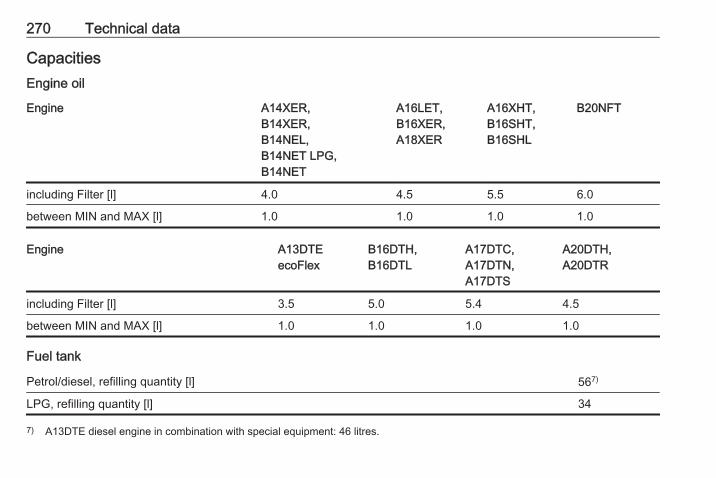
270 Technical data
CapacitiesEngine oil
Engine A14XER,B14XER,B14NEL,B14NET LPG,B14NET
A16LET,B16XER,A18XER
A16XHT,B16SHT,B16SHL
B20NFT
including Filter [l] 4.0 4.5 5.5 6.0
between MIN and MAX [l] 1.0 1.0 1.0 1.0
Engine A13DTEecoFlex
B16DTH,B16DTL
A17DTC,A17DTN,A17DTS
A20DTH,A20DTR
including Filter [l] 3.5 5.0 5.4 4.5
between MIN and MAX [l] 1.0 1.0 1.0 1.0
Fuel tank
Petrol/diesel, refilling quantity [l] 567)
LPG, refilling quantity [l] 34
7) A13DTE diesel engine in combination with special equipment: 46 litres.
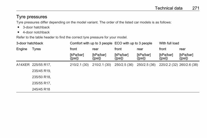
Technical data 271
Tyre pressuresTyre pressures differ depending on the model variant. The order of the listed car models is as follows:● 3-door hatchback● 4-door notchback
Refer to the table header to find the correct tyre pressure for your model.
3-door hatchback Comfort with up to 3 people ECO with up to 3 people With full loadEngine Tyres front rear front rear front rear
[kPa/bar]([psi])
[kPa/bar]([psi])
[kPa/bar]([psi])
[kPa/bar]([psi])
[kPa/bar]([psi])
[kPa/bar]([psi])
A14XER 225/55 R17, 210/2.1 (30) 210/2.1 (30) 250/2.5 (36) 250/2.5 (36) 220/2.2 (32) 260/2.6 (38)
235/45 R19,
235/50 R18,
235/55 R17,
245/45 R18
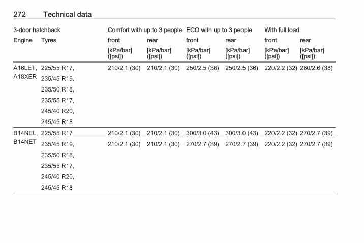
272 Technical data
3-door hatchback Comfort with up to 3 people ECO with up to 3 people With full loadEngine Tyres front rear front rear front rear
[kPa/bar]([psi])
[kPa/bar]([psi])
[kPa/bar]([psi])
[kPa/bar]([psi])
[kPa/bar]([psi])
[kPa/bar]([psi])
A16LET,A18XER
225/55 R17, 210/2.1 (30) 210/2.1 (30) 250/2.5 (36) 250/2.5 (36) 220/2.2 (32) 260/2.6 (38)
235/45 R19,
235/50 R18,
235/55 R17,
245/40 R20,
245/45 R18
B14NEL,B14NET
225/55 R17 210/2.1 (30) 210/2.1 (30) 300/3.0 (43) 300/3.0 (43) 220/2.2 (32) 270/2.7 (39)
235/45 R19, 210/2.1 (30) 210/2.1 (30) 270/2.7 (39) 270/2.7 (39) 220/2.2 (32) 270/2.7 (39)
235/50 R18,
235/55 R17,
245/40 R20,
245/45 R18

Technical data 273
3-door hatchback Comfort with up to 3 people ECO with up to 3 people With full loadEngine Tyres front rear front rear front rear
[kPa/bar]([psi])
[kPa/bar]([psi])
[kPa/bar]([psi])
[kPa/bar]([psi])
[kPa/bar]([psi])
[kPa/bar]([psi])
A16XHT,B16SHT,A20DTH,A20DTR,B16DTH,B16DTL,B16SHL
225/55 R17 230/2.3 (33) 230/2.3 (33) 300/3.0 (43) 300/3.0 (43) 240/2.4 (35) 280/2.8 (41)
235/45 R19, 230/2.3 (33) 230/2.3 (33) 270/2.7 (39) 270/2.7 (39) 240/2.4 (35) 280/2.8 (41)
235/50 R18,
235/55 R17,
245/40 R20,
245/45 R18
B20NFT 235/45 R18, 240/2.4 (35) 240/2.4 (35) 270/2.7 (39) 280/2.8 (41) 260/2.6 (38) 300/3.0 (43)
245/40 R19
245/35 R20 270/2.7 (39) 250/2.5 (36) 280/2.8 (41) 290/2.9 (42) 280/2.8 (41) 310/3.1 (44)
All Temporary spare wheelT125/70 R17
420/4.2 (61) 420/4.2 (61) – – 420/4.2 (61) 420/4.2 (61)

274 Technical data
4-door notchbackComfort with up to3 people ECO with up to 3 people
With full load
Engine Tyres front rear front rear front rear[kPa/bar]([psi])
[kPa/bar]([psi])
[kPa/bar]([psi])
[kPa/bar]([psi])
[kPa/bar]([psi])
[kPa/bar]([psi])
B14NET LPG,B14NET
205/60 R16, 220/2.2 (32) 220/2.2 (32) 270/2.7 (39) 270/2.7 (39) 230/2.3(33)
270/2.7(39)
205/65 R16,
215/50 R17,
215/60 R16,
225/45 R18,
225/50 R17,
235/40 R19
B14XER 205/60 R16, 220/2.2 (32) 220/2.2 (32) 270/2.7 (39) 270/2.7 (39) 230/2.3(33)
270/2.7(39)
215/50 R17,
215/60 R16
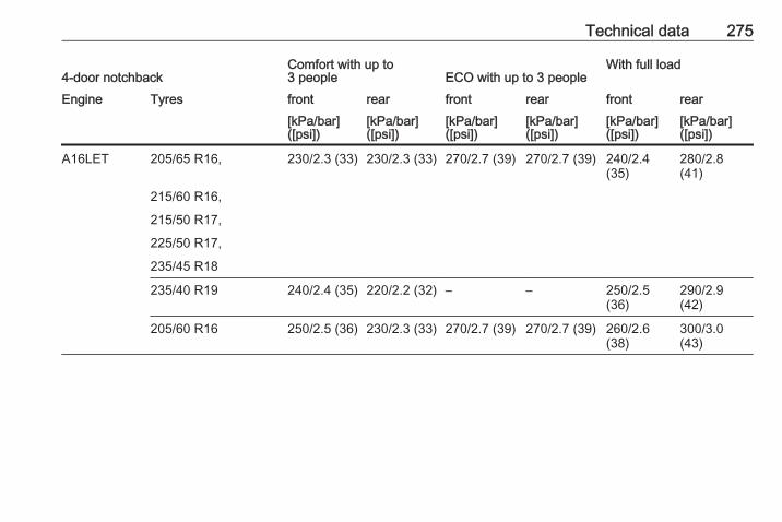
Technical data 275
4-door notchbackComfort with up to3 people ECO with up to 3 people
With full load
Engine Tyres front rear front rear front rear[kPa/bar]([psi])
[kPa/bar]([psi])
[kPa/bar]([psi])
[kPa/bar]([psi])
[kPa/bar]([psi])
[kPa/bar]([psi])
A16LET 205/65 R16, 230/2.3 (33) 230/2.3 (33) 270/2.7 (39) 270/2.7 (39) 240/2.4(35)
280/2.8(41)
215/60 R16,
215/50 R17,
225/50 R17,
235/45 R18
235/40 R19 240/2.4 (35) 220/2.2 (32) – – 250/2.5(36)
290/2.9(42)
205/60 R16 250/2.5 (36) 230/2.3 (33) 270/2.7 (39) 270/2.7 (39) 260/2.6(38)
300/3.0(43)

276 Technical data
4-door notchbackComfort with up to3 people ECO with up to 3 people
With full load
Engine Tyres front rear front rear front rear[kPa/bar]([psi])
[kPa/bar]([psi])
[kPa/bar]([psi])
[kPa/bar]([psi])
[kPa/bar]([psi])
[kPa/bar]([psi])
B16XER 205/60 R16, 220/2.2 (32) 220/2.2 (32) 270/2.7 (39) 270/2.7 (39) 230/2.3(33)
270/2.7(39)
215/50 R17,
215/60 R16,
225/45 R18,
235/40 R19
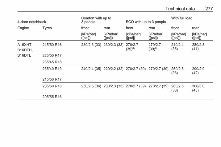
Technical data 277
4-door notchbackComfort with up to3 people ECO with up to 3 people
With full load
Engine Tyres front rear front rear front rear[kPa/bar]([psi])
[kPa/bar]([psi])
[kPa/bar]([psi])
[kPa/bar]([psi])
[kPa/bar]([psi])
[kPa/bar]([psi])
A16XHT,B16DTH,B16DTL
215/60 R16, 230/2.3 (33) 230/2.3 (33) 270/2.7(39)8)
270/2.7(39)8)
240/2.4(35)
280/2.8(41)
225/50 R17,
235/45 R18
235/40 R19, 240/2.4 (35) 220/2.2 (32) 270/2.7 (39) 270/2.7 (39) 250/2.5(36)
290/2.9(42)
215/50 R17
205/60 R16, 250/2.5 (36) 230/2.3 (33) 270/2.7 (39) 270/2.7 (39) 260/2.6(38)
300/3.0(43)
205/55 R16
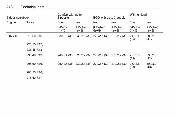
278 Technical data
4-door notchbackComfort with up to3 people ECO with up to 3 people
With full load
Engine Tyres front rear front rear front rear[kPa/bar]([psi])
[kPa/bar]([psi])
[kPa/bar]([psi])
[kPa/bar]([psi])
[kPa/bar]([psi])
[kPa/bar]([psi])
B16SHL 215/60 R16, 230/2.3 (33) 230/2.3 (33) 270/2.7 (39) 270/2.7 (39) 240/2.4(35)
280/2.8(41)
225/50 R17,
235/45 R18
235/40 R19 240/2.4 (35) 220/2.2 (32) 270/2.7 (39) 270/2.7 (39) 250/2.5(36)
290/2.9(42)
205/60 R16, 250/2.5 (36) 230/2.3 (33) 270/2.7 (39) 270/2.7 (39) 260/2.6(38)
300/3.0(43)
205/55 R16,
215/50 R17
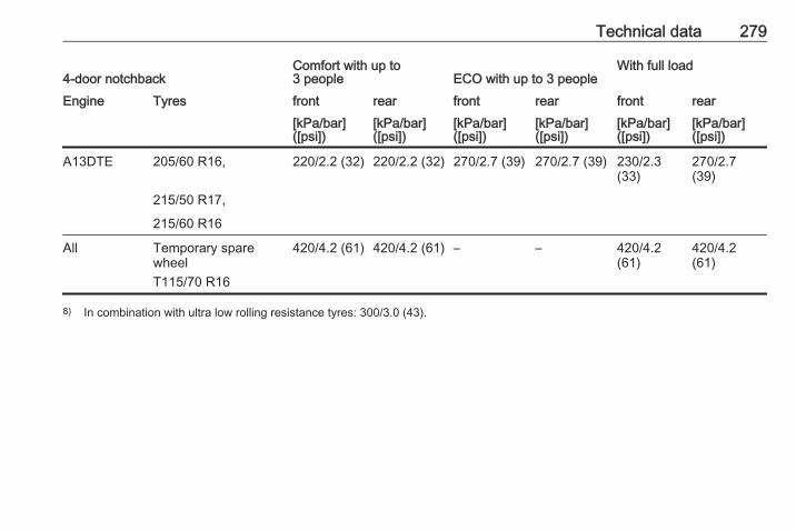
Technical data 279
4-door notchbackComfort with up to3 people ECO with up to 3 people
With full load
Engine Tyres front rear front rear front rear[kPa/bar]([psi])
[kPa/bar]([psi])
[kPa/bar]([psi])
[kPa/bar]([psi])
[kPa/bar]([psi])
[kPa/bar]([psi])
A13DTE 205/60 R16, 220/2.2 (32) 220/2.2 (32) 270/2.7 (39) 270/2.7 (39) 230/2.3(33)
270/2.7(39)
215/50 R17,
215/60 R16
All Temporary sparewheelT115/70 R16
420/4.2 (61) 420/4.2 (61) – – 420/4.2(61)
420/4.2(61)
8) In combination with ultra low rolling resistance tyres: 300/3.0 (43).
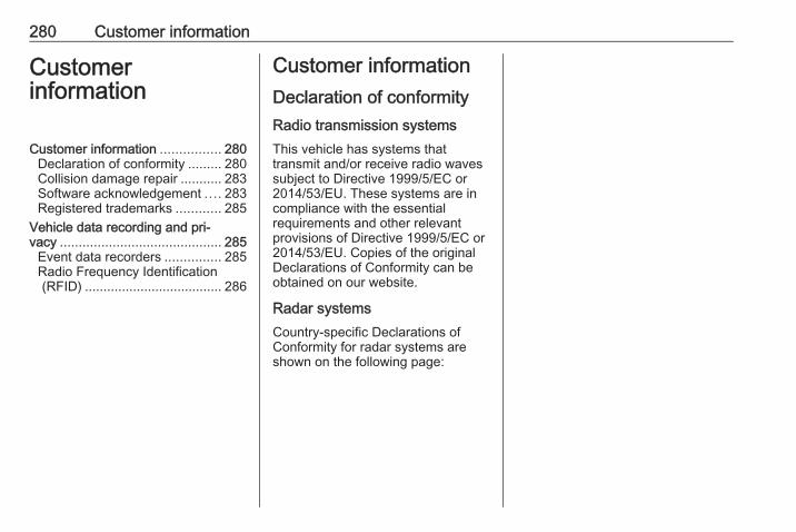
280 Customer information
Customerinformation
Customer information ................ 280Declaration of conformity ......... 280Collision damage repair ........... 283Software acknowledgement .... 283Registered trademarks ............ 285
Vehicle data recording and pri‐vacy ........................................... 285
Event data recorders ............... 285Radio Frequency Identification(RFID) ..................................... 286
Customer informationDeclaration of conformityRadio transmission systemsThis vehicle has systems thattransmit and/or receive radio wavessubject to Directive 1999/5/EC or2014/53/EU. These systems are incompliance with the essentialrequirements and other relevantprovisions of Directive 1999/5/EC or2014/53/EU. Copies of the originalDeclarations of Conformity can beobtained on our website.
Radar systemsCountry-specific Declarations ofConformity for radar systems areshown on the following page:
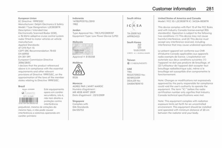
Customer information 281
282 Customer information
Jack
Customer information 283
Translation of the original declarationof conformityDeclaration of conformity accordingto EC Directive 2006/42/ECWe declare that the product:Product designation: JackType/GM part number: 13576735is in compliance with the provisions ofDirective 2006/42/EC.Applied technical standards:GMN9737 : jackingGM 14337 : standard equipment
jack – hardwaretests
GMN5127 : vehicle integrity –hoisting and servicestation jacking
GMW15005 : standard equipmentjack and spare tyre,vehicle test
ISO TS 16949 : qualitymanagementsystems
The signatory is authorised tocompile the technical documentation.Rüsselsheim, 31st January 2014signed byHans-Peter MetzgerEngineering Group Manager Chassis& StructureAdam Opel AGD-65423 Rüsselsheim
Collision damage repairPaint thicknessDue to production techniques, thethickness of the paint can varybetween 50 and 400 µm.Therefore, different paint thickness isno indicator for a collision damagerepair.
Software acknowledgementCertain OnStar components includelibcurl and unzip software and otherthird party software. Below are thenotices and licenses associated withlibcurl and unzip and for other thirdparty software please see http://www.lg.com/global/support/opensource/index.
libcurlCopyright and permission noticeCopyright (c) 1996 - 2010, DanielStenberg, <[email protected]>.All rights reserved.Permission to use, copy, modify, anddistribute this software for anypurpose with or without fee is herebygranted, provided that the abovecopyright notice and this permissionnotice appear in all copies.The software is provided "as is",without warranty of any kind, expressor implied, including but not limited tothe warranties of merchantability,fitness for a particular purpose andnoninfringement of third party rights.In no event shall the authors or
284 Customer information
copyright holders be liable for anyclaim, damages or other liability,whether in an action of contract, tortor otherwise, arising from, out of or inconnection with the software or theuse or other dealings in the software.Except as contained in this notice, thename of a copyright holder shall notbe used in advertising or otherwise topromote the sale, use or otherdealings in this Software without priorwritten authorization of the copyrightholder.
unzipThis is version 2005-Feb-10 of theInfo-ZIP copyright and license. Thedefinitive version of this documentshould be available at ftp://ftp.info-zip.org/pub/infozip/license.htmlindefinitely.Copyright (c) 1990-2005 Info-ZIP. Allrights reserved.For the purposes of this copyright andlicense, “Info-ZIP” is defined as thefollowing set of individuals:Mark Adler, John Bush, Karl Davis,Harald Denker, Jean-Michel Dubois,Jean-loup Gailly, Hunter Goatley, Ed
Gordon, Ian Gorman, Chris Herborth,Dirk Haase, Greg Hartwig, RobertHeath, Jonathan Hudson, PaulKienitz, David Kirschbaum, JohnnyLee, Onno van der Linden, IgorMandrichenko, Steve P. Miller, SergioMonesi, Keith Owens, GeorgePetrov, Greg Roelofs, Kai UweRommel, Steve Salisbury, DaveSmith, Steven M. Schweda, ChristianSpieler, Cosmin Truta, AntoineVerheijen, Paul von Behren, RichWales, Mike White.This software is provided “as is,”without warranty of any kind, expressor implied. In no event shall Info-ZIPor its contributors be held liable forany direct, indirect, incidental, specialor consequential damages arising outof the use of or inability to use thissoftware.Permission is granted to anyone touse this software for any purpose,including commercial applications,and to alter it and redistribute it freely,subject to the following restrictions:
1. Redistributions of source codemust retain the above copyrightnotice, definition, disclaimer, andthis list of conditions.
2. Redistributions in binary form(compiled executables) mustreproduce the above copyrightnotice, definition, disclaimer, andthis list of conditions indocumentation and/or othermaterials provided with thedistribution. The sole exception tothis condition is redistribution of astandard UnZipSFX binary(including SFXWiz) as part of aself-extracting archive; that ispermitted without inclusion of thislicense, as long as the normalSFX banner has not beenremoved from the binary ordisabled.
3. Altered versions--including, butnot limited to, ports to newoperating systems, existing portswith new graphical interfaces, anddynamic, shared, or static libraryversions--must be plainly markedas such and must not bemisrepresented as being the
Customer information 285
original source. Such alteredversions also must not bemisrepresented as being Info-ZIPreleases--including, but notlimited to, labeling of the alteredversions with the names “Info-ZIP” (or any variation thereof,including, but not limited to,different capitalizations), “PocketUnZip,” “WiZ” or “MacZip” withoutthe explicit permission of Info-ZIP.Such altered versions are furtherprohibited from misrepresentativeuse of the Zip-Bugs or Info-ZIP e-mail addresses or of the Info-ZIPURL(s).
4. Info-ZIP retains the right to usethe names “Info-ZIP,” “Zip,”“UnZip,” “UnZipSFX,” “WiZ,”“Pocket UnZip,” “Pocket Zip,” and“MacZip” for its own source andbinary releases.
Registered trademarksApple Inc.Apple CarPlay™ is a trademark ofApple Inc.App Store® is a registered trademarkof Apple Inc.
iPhone® and iPod® are registeredtrademarks of Apple Inc.Aupeo! GmbHAUPEO® is a registered trademark ofthe Aupeo! GmbH.Bluetooth SIG, Inc.Bluetooth® is a registered trademarkof Bluetooth SIG, Inc.EnGIS Technologies, Inc.BringGo® is a registered trademark ofEnGIS Technologies, Inc.Google Inc.Android™, Android Auto™ andGoogle Play™ Store are trademarksof Google Inc.Verband der Automobilindustrie e.V.AdBlue® is a registered trademark ofthe VDA.
Vehicle data recordingand privacyEvent data recordersData storage modules in thevehicleA large number of electroniccomponents of your vehicle containdata storage modules temporarily orpermanently storing technical dataabout the condition of the vehicle,events and errors. In general, thistechnical information documents thecondition of parts, modules, systemsor the environment:● operating conditions of system
components (e.g. filling levels)● status messages of the vehicle
and its single components (e.g.number of wheel revolutions /rotational speed, deceleration,lateral acceleration)
● dysfunctions and defects inimportant system components
286 Customer information
● vehicle reactions in particulardriving situations (e.g. inflation ofan airbag, activation of thestability regulation system)
● environmental conditions (e.g.temperature)
These data are exclusively technicaland help identifying and correctingerrors as well as optimising vehiclefunctions.Motion profiles indicating travelledroutes cannot be created with thesedata.If services are used (e.g. repairworks, service processes, warrantycases, quality assurance),employees of the service network(manufacturer included) are able toread out this technical informationfrom the event and error data storagemodules applying special diagnosticdevices. If required, you will receivefurther information at theseworkshops. After an error has beencorrected, the data are deleted fromthe error storage module or they areconstantly overwritten.
When using the vehicle, situationsmay occur in which these technicaldata related to other information(accident report, damages on thevehicle, witness statements etc.) maybe associated with a specific person -possibly, with the assistance of anexpert.Additional functions contractuallyagreed upon with the client (e.g.vehicle location in emergency cases)allow the transmission of particularvehicle data from the vehicle.
Radio FrequencyIdentification (RFID)RFID technology is used in somevehicles for functions such as tyrepressure monitoring and ignitionsystem security. It is also used inconnection with conveniences suchas radio remote controls for doorlocking/unlocking and starting, and in-vehicle transmitters for garage dooropeners. RFID technology in Opelvehicles does not use or recordpersonal information or link with anyother Opel system containingpersonal information.

Customer information 287
288
Index AAccessories and vehicle
modifications .......................... 201Active Emergency Braking......... 173Active head restraints................... 40Adaptive cruise control......... 92, 162Adaptive forward lighting .... 92,
120, 212Adjustable air vents ................... 137Airbag and belt tensioners ........... 87Airbag deactivation ................ 53, 87Airbag system .............................. 51Air conditioning regular
operation ................................ 138Air conditioning system .............. 130Air intake .................................... 137Air vents...................................... 137Antilock brake system ................ 151Antilock brake system (ABS) ....... 89Anti-theft alarm system ................ 29Anti-theft locking system .............. 29Appearance care........................ 250Armrest................................... 47, 48Armrest storage ........................... 63Ashtrays ....................................... 80Automatic anti-dazzle .................. 33Automatic light control ............... 117Automatic locking ........................ 26Automatic transmission ............. 147
Autostop..................................... 142Auxiliary heater........................... 136
BBattery discharge protection ...... 128Battery voltage ........................... 102Belts.............................................. 48Bonnet ....................................... 202Brake and clutch fluid................. 255Brake and clutch system ............. 88Brake assist ............................... 154Brake fluid .................................. 206Brakes ............................... 151, 206Breakdown.................................. 248Bulb replacement ....................... 209
CCapacities .................................. 270Car Pass ...................................... 23Catalytic converter ..................... 146Central locking system ................ 24Centre console lighting .............. 127Centre console storage ............... 64Changing tyre and wheel size . . . 235Charging system .......................... 88Child locks ................................... 26Child restraint installation
locations ................................... 57Child restraints.............................. 55Child restraint systems ................ 55Cigarette lighter ........................... 80

289
Climate control ............................. 17Climate control systems............. 129Clock............................................. 78Code............................................. 99Collision damage repair.............. 283Control indicators.......................... 84Control of the vehicle ................. 140Controls........................................ 74Convex shape .............................. 31Coolant and antifreeze............... 255Cruise control ...................... 92, 159Cupholders .................................. 61Curtain airbag system .................. 53Curve lighting.............................. 120
DDanger, Warnings and Cautions . . . 4Daytime running lights ............... 120Declaration of conformity............ 280Diesel fuel system bleeding ....... 208Diesel particle filter............... 90, 145Door open .................................... 93Doors............................................ 27Driver assistance systems.......... 159Driver Information Centre............. 93Driving characteristics and
towing tips .............................. 195Driving hints................................ 140
EElectric adjustment ...................... 31Electrical system......................... 223Electric parking brake........... 88, 152Electric parking brake fault........... 89Electronic climate control system 132Electronic driving programmes . . 149Electronic Stability Control.......... 155Electronic Stability Control and
Traction Control system............ 90Electronic Stability Control off....... 90End-of-life vehicle recovery ....... 202Engine compartment fuse box ... 224Engine coolant ........................... 204Engine coolant temperature
gauge ....................................... 82Engine data ............................... 262Engine exhaust .......................... 145Engine identification................... 258Engine oil ................... 203, 255, 259Engine oil pressure ...................... 91Entry lighting .............................. 127ERA GLONASS.......................... 113Event data recorders.................. 285Exit lighting ................................ 127Exterior care .............................. 250Exterior light ................................. 92Exterior lighting .................... 15, 116Exterior mirrors............................. 31
FFault ........................................... 149First aid......................................... 70First aid kit ................................... 70Fixed air vents ........................... 137Fog light ....................................... 92Fog lights ................................... 213Folding mirrors ............................. 32Following distance indication...... 172Forward collision alert................. 169Front airbag system ..................... 51Front fog lights ........................... 124Front seats.................................... 41Front storage................................ 62Front turn signal lights ............... 215Fuel............................................. 188Fuel consumption - CO2-
Emissions ............................... 194Fuel for diesel engines .............. 188Fuel for liquid gas operation....... 189Fuel for petrol engines ............... 188Fuel gauge ................................... 82Fuel selector ................................ 82Fuses ......................................... 223
GGauges......................................... 81General information ................... 195Glass panel .................................. 38
290
Glovebox ..................................... 61Graphic-Info-Display, Colour-
Info-Display .............................. 97
HHalogen headlights .................... 209Hand brake......................... 151, 152Hazard warning flashers ............ 123Headlight flash ........................... 118Headlight range adjustment ...... 119Headlights................................... 116Headlights when driving abroad 119Head restraint adjustment ............. 8Head restraints ............................ 39Heated mirrors ............................. 32Heated rear window ..................... 36Heated steering wheel ................. 74Heating ........................................ 47Heating and ventilation system . 129Height adjustable rear floor cover 68High beam ........................... 92, 118High beam assist.................. 92, 118Hill start assist ........................... 154Horn ....................................... 16, 75
IIdentification plate ..................... 257Ignition switch positions ............. 141Immobiliser ............................ 31, 92Indicators...................................... 81Information displays...................... 93
Instrument cluster ........................ 81Instrument panel fuse box ......... 226Instrument panel illumination ..... 222Instrument panel illumination
control .................................... 125Instrument panel overview ........... 11Interactive driving system........... 156Interior care ............................... 253Interior lighting............................ 125Interior lights ...................... 125, 222Interior mirrors.............................. 33Interruption of power supply ...... 150Introduction .................................... 3ISOFIX child restraint systems .... 60
JJump starting ............................. 247
KKey, memorised settings.............. 24Keys ............................................. 22Keys, locks................................... 22
LLane departure warning....... 89, 187Lashing eyes ............................... 69Lighting features......................... 127Light switch ................................ 116Load compartment ................ 27, 65Load compartment cover ............. 67Load compartment fuse box ...... 227
Loading information ..................... 71Low fuel ....................................... 91Low washer fluid .......................... 92
MMalfunction indicator light ............ 88Manual anti-dazzle ...................... 33Manual mode ............................. 149Manual seat adjustment............... 42Manual transmission .................. 151Manual windows .......................... 34Memorised settings...................... 24Midlevel-Display........................... 93Mirror adjustment ........................... 9Misted light covers ..................... 125
NNew vehicle running-in .............. 140Number plate light ..................... 222
OObject detection systems........... 175Odometer ..................................... 81Oil, engine.......................... 255, 259OnStar........................................ 110Operate pedal............................... 88Outside temperature .................... 77Overrun cut-off ........................... 142
291
PParking ................................ 20, 144Parking assist ............................ 175Parking brake ............................ 152Parking lights ............................. 124Particulate filter........................... 145Performance .............................. 265Performing work ........................ 202Pollen filter ................................. 137Power outlets ............................... 79Power seat adjustment ................ 45Power steering.............................. 89Power steering fluid.................... 205Power windows ............................ 34Preheating ................................... 90Puncture..................................... 239
QQuickheat................................... 136
RRadio Frequency Identification
(RFID)..................................... 286Radio remote control ................... 23Reading lights ............................ 126Rear floor storage cover .............. 68Rear fog light ............................... 92Rear fog lights ........................... 124Rear seats.................................... 48Rear storage................................. 67Rear window wiper/washer .......... 77
Recommended fluids andlubricants ........................ 255, 259
Reduced engine power................ 92Refuelling ................................... 191Registered trademarks............... 285Retained power off..................... 141Reversing lights ......................... 125Ride control systems.................. 154Roof.............................................. 36Roof load...................................... 71Roof rack ..................................... 71
SSafety belts................................... 48Seat adjustment ............................. 7Seat belt ........................................ 9Seat belt reminder ....................... 87Seat belts ..................................... 48Seat folding .................................. 44Seat heating................................. 47Seat position ................................ 41Selector lever ............................. 148Service ............................... 138, 254Service display ............................ 83Service information .................... 254Service vehicle soon .................... 88Side airbag system ...................... 52Side blind spot alert.................... 182Sidelights.................................... 116Side turn signal lights ................ 220
Smartphone controller.................. 99Software acknowledgement....... 283Spare wheel ............................... 243Speed limiter............................... 161Speedometer ............................... 81Starting and operating................ 140Starting off ................................... 19Starting the engine .................... 141Steering...................................... 140Steering wheel adjustment .... 10, 74Steering wheel controls ............... 74Stop-start system........................ 142Storage......................................... 61Storage compartments................. 61Sunroof ........................................ 36Sunvisor lights ........................... 126Sun visors .................................... 36Symbols ......................................... 4
TTachometer ................................. 81Tail lights ................................... 217Three-point seat belt .................... 49Tools .......................................... 228Top-tether fastening eyes ............ 60Tow bar....................................... 195Towing................................ 195, 248Towing another vehicle ............. 249Towing equipment ..................... 196Towing the vehicle ..................... 248
292
Traction Control system ............. 154Traction Control system off........... 90Traffic sign assistant................... 183Trailer coupling........................... 195Trailer stability assist ................. 199Trailer towing ............................. 195Transmission ............................... 19Transmission display ................. 147Tread depth ............................... 235Trip computer ............................ 103Trip odometer .............................. 81Turn and lane-change signals ... 123Turn signal ................................... 87Tyre chains ................................ 236Tyre designations ...................... 230Tyre pressure ............................ 230Tyre pressure monitoring
system............................... 91, 232Tyre pressures ........................... 271Tyre repair kit ............................. 236
UUltrasonic parking assist ...... 90, 175Underseat storage ....................... 63Upholstery.................................. 253Uplevel-Combi-Display................. 93Upshift.......................................... 89Using this manual .......................... 3
VVehicle battery ........................... 206Vehicle checks............................ 202Vehicle data................................ 259Vehicle data recording and
privacy..................................... 285Vehicle detected ahead................ 93Vehicle dimensions .................... 269Vehicle Identification Number .... 257Vehicle jack................................ 228Vehicle messages ....................... 99Vehicle personalisation ............. 105Vehicle security............................ 29Vehicle specific data ...................... 3Vehicle storage........................... 201Vehicle tools............................... 228Vehicle unlocking ........................... 6Vehicle weight ........................... 267Ventilation................................... 129
WWarning chimes ......................... 102Warning lights............................... 81Warning triangle .......................... 70Washer and wiper systems ......... 17Washer fluid ............................... 205Wheel changing ......................... 239Wheel covers ............................. 236Wheels and tyres ....................... 230Windows....................................... 33
Windscreen................................... 33Windscreen wiper/washer ........... 75Winter tyres ............................... 230Wiper blade replacement .......... 208
www.opel.com
Copyright by ADAM OPEL AG, Rüsselsheim, Germany.
The information contained in this publication is effective as of the date indicated below. Adam Opel AG reserves the right to make changes to the technical specifications, features anddesign of the vehicles relative to the information in this publication as well as changes to the publication itself.
Edition: August 2016, ADAM OPEL AG, Rüsselsheim.
Printed on chlorine-free bleached paper.
*ID-OASJOBSE1608-EN*
ID-OASJOBSE1608-en