ASTM F-1387 INTERMIX TEST
8
ASTM F-1387 INTERMIX TEST The purpose of this test procedure is to establish that any intermixed combination of DK-LOK ® and Swagelok ® individual components will provide leak-free performance synonymous with pure assemblies when subjected to various conditions inherent to the environments for which compression tube fittings are commonly exposed in practical everyday installations. Mobile, AL Houston, TX Salt Lake City, UT www.dklokusa.com (800) 328-5803
Transcript of ASTM F-1387 INTERMIX TEST

ASTM F-1387 INTERMIX TEST
The purpose of this test procedure is to establish that any intermixed combination of DK-LOK® and Swagelok® individual components will provide leak-free performance
synonymous with pure assemblies when subjected to various conditions inherent to the environments for which
compression tube fittings are commonly exposed in practical everyday installations.
Mobile, AL Houston, TX Salt Lake City, UT www.dklokusa.com (800) 328-5803
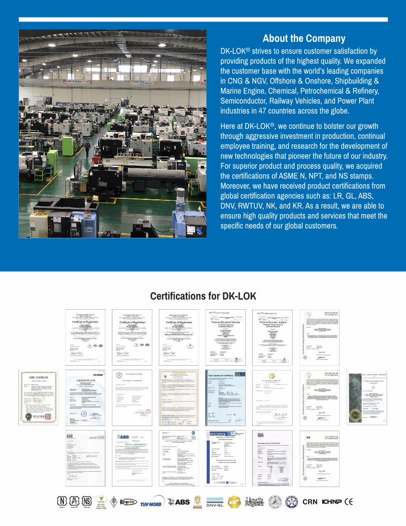
About the CompanyDK-LOK® strives to ensure customer satisfaction by providing products of the highest quality. We expanded the customer base with the world’s leading companies in CNG & NGV, Offshore & Onshore, Shipbuilding & Marine Engine, Chemical, Petrochemical & Refinery, Semiconductor, Railway Vehicles, and Power Plant industries in 47 countries across the globe.
Here at DK-LOK®, we continue to bolster our growth through aggressive investment in production, continual employee training, and research for the development of new technologies that pioneer the future of our industry. For superior product and process quality, we acquired the certifications of ASME N, NPT, and NS stamps. Moreover, we have received product certifications from global certification agencies such as: LR, GL, ABS, DNV, RWTUV, NK, and KR. As a result, we are able to ensure high quality products and services that meet the specific needs of our global customers.
Certifications for DK-LOK
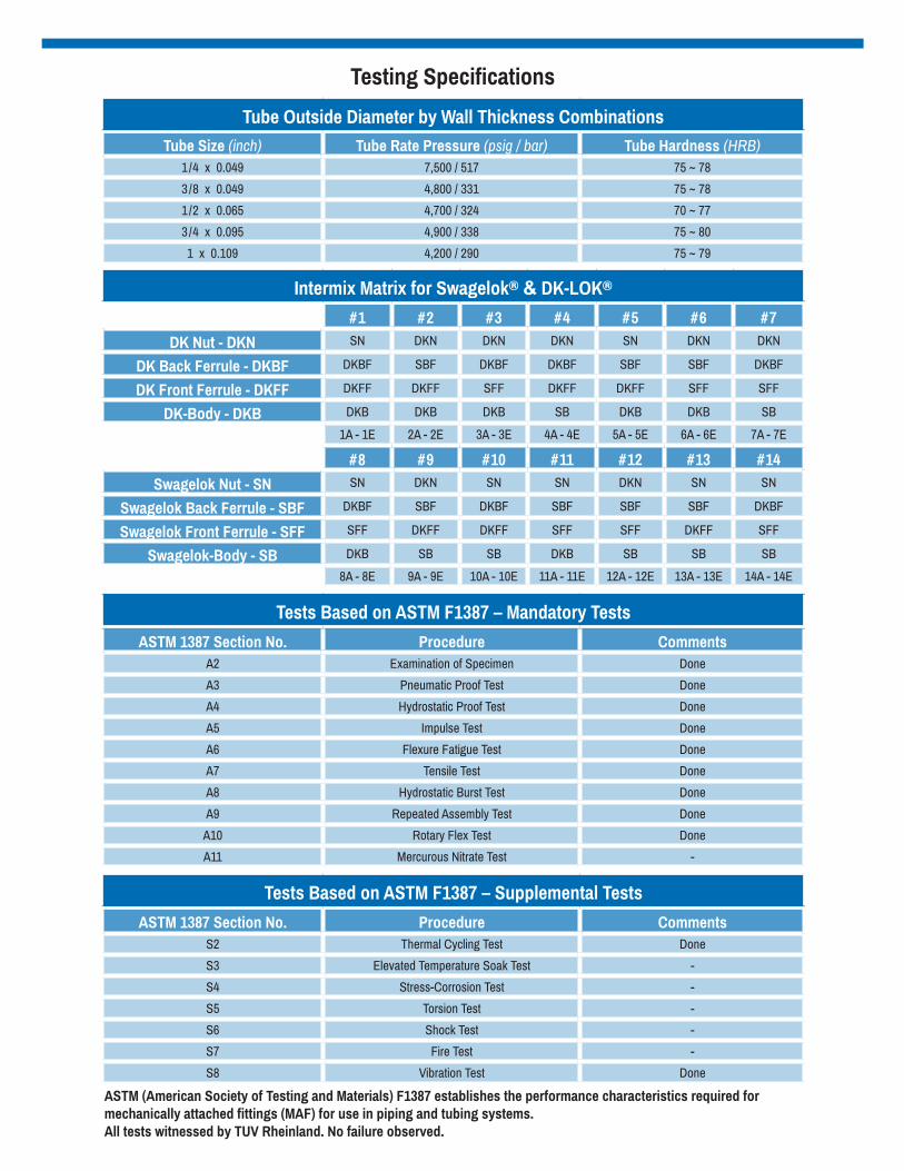
Testing Specifications
Tube Outside Diameter by Wall Thickness CombinationsTube Size (inch) Tube Rate Pressure (psig / bar) Tube Hardness (HRB)
1/4 x 0.049 7,500 / 517 75 ~ 78
3/8 x 0.049 4,800 / 331 75 ~ 78
1/2 x 0.065 4,700 / 324 70 ~ 77
3/4 x 0.095 4,900 / 338 75 ~ 80
1 x 0.109 4,200 / 290 75 ~ 79
Intermix Matrix for Swagelok® & DK-LOK®
#1 #2 #3 #4 #5 #6 #7DK Nut - DKN SN DKN DKN DKN SN DKN DKN
DK Back Ferrule - DKBF DKBF SBF DKBF DKBF SBF SBF DKBF
DK Front Ferrule - DKFF DKFF DKFF SFF DKFF DKFF SFF SFF
DK-Body - DKB DKB DKB DKB SB DKB DKB SB
1A - 1E 2A - 2E 3A - 3E 4A - 4E 5A - 5E 6A - 6E 7A - 7E
#8 #9 #10 #11 #12 #13 #14Swagelok Nut - SN SN DKN SN SN DKN SN SN
Swagelok Back Ferrule - SBF DKBF SBF DKBF SBF SBF SBF DKBF
Swagelok Front Ferrule - SFF SFF DKFF DKFF SFF SFF DKFF SFF
Swagelok-Body - SB DKB SB SB DKB SB SB SB
8A - 8E 9A - 9E 10A - 10E 11A - 11E 12A - 12E 13A - 13E 14A - 14E
Tests Based on ASTM F1387 – Mandatory TestsASTM 1387 Section No. Procedure Comments
A2 Examination of Specimen Done
A3 Pneumatic Proof Test Done
A4 Hydrostatic Proof Test Done
A5 Impulse Test Done
A6 Flexure Fatigue Test Done
A7 Tensile Test Done
A8 Hydrostatic Burst Test Done
A9 Repeated Assembly Test Done
A10 Rotary Flex Test Done
A11 Mercurous Nitrate Test -
Tests Based on ASTM F1387 – Supplemental TestsASTM 1387 Section No. Procedure Comments
S2 Thermal Cycling Test Done
S3 Elevated Temperature Soak Test -
S4 Stress-Corrosion Test -
S5 Torsion Test -
S6 Shock Test -
S7 Fire Test -
S8 Vibration Test Done
ASTM (American Society of Testing and Materials) F1387 establishes the performance characteristics required for mechanically attached fittings (MAF) for use in piping and tubing systems.All tests witnessed by TUV Rheinland. No failure observed.

Hydrostatic Proof Test Results – 3X F-1387 RequirementsAll test data was measured and recorded with calibrated gauges in accordance with ASTM F-1387 requirements.
1. Each spool containing specimens was mounted in the test chamber with one end free to move.
2. Each spool was filled with water.3. Each spool was pressurized to 100 PSI for 5 minutes.4. After observing no leakage, the pressure was gradually
increased to 150% of the rated working pressure of the tube, and held for an additional 5 minutes.
5. After observing no leakage, the spool was depressurized and drained.
6. Each specimen was disassembled and reassembled two times.7. Steps 1 through 6 were then repeated with no leakage.8. Steps 1 through 4 were then repeated. The Hydrostatic
Proof test was conducted three times. After the third run, no make and break was conducted as the spools were then subjected to the Hydrostatic Burst Test.
Pneumatic Proof Test Results – 3X F-1387 RequirementsAll test data was measured and recorded with calibrated gauges in accordance with ASTM F-1387 requirements.
1. Each spool containing specimens was submerged under water.
2. Each spool was pressurized to 100 psi using Nitrogen(N2) for 5 minutes.
3. The first minute allowed for the dissipation of surface bubbles.4. After 5 minutes observing no leakage, the pressure
was gradually increased to 125% of the rated working pressure of the tube, and held for 5 minutes.
5. No leakage was observed.6. After completing the first Pneumatic Proof, each specimen
was disassembled and reassembled two times.7. Steps 1 through 6 were repeated a second and third time
with no leakage.8. The Pneumatic Proof test was conducted three times.
ASTM F-1387 only requires one run. Additionally, the test was conducted at 125% of the rated working pressure of the tube. ASTM F-1387 only requires 125% of the rated working pressure of the tube or 500 PSI –
WHICHEVER IS LOWER.
Size / Test Pressure Tube Rate Pressure Pressure
1/4”T x .049” 7,500 PSI x 125% 9,375 PSI
3/8”T x .049” 4,800 PSI x 125% 6,000 PSI
1/2”T x .065” 4,700 PSI x 125% 5,875 PSI
3/4”T x .095” 4,900 PSI x 125% 6,125 PSI
1”T x .109” 4,200 PSI x 125% 5,250 PSI
Size / Hydro Pressure Tube Rate Pressure Pressure
1/4”T x .049” 7,500 PSI x 150% 11,250 PSI
3/8”T x .049” 4,800 PSI x 150% 7,200 PSI
1/2”T x .065” 4,700 PSI x 150% 7,050 PSI
3/4”T x .095” 4,900 PSI x 150% 7,350 PSI
1”T x .109” 4,200 PSI x 150% 6,300 PSI
The original specimens were subjected to all three Pneumatic Proof Tests and all three Hydrostatic Proof Tests(including 10 repeat assemblies), concluding with the Hydrostatic Burst Test (destructive test). New specimens wereintroduced for each of the remaining test.
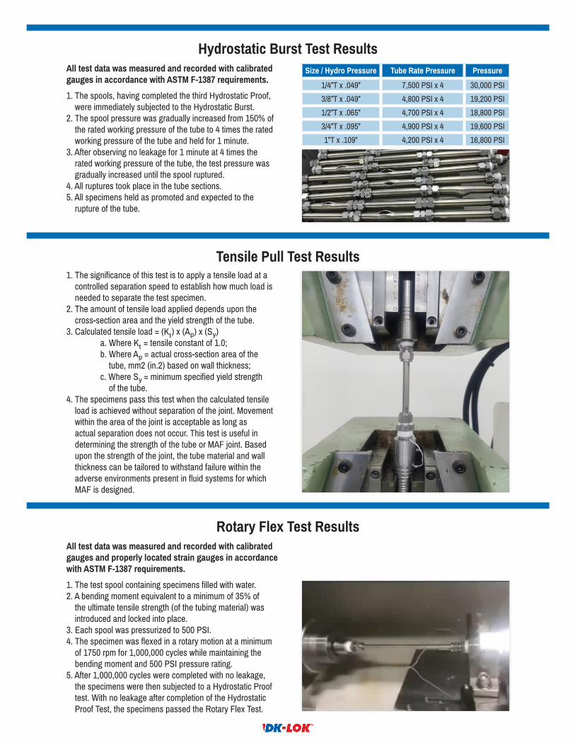
Tensile Pull Test Results.
1. The significance of this test is to apply a tensile load at a controlled separation speed to establish how much load is needed to separate the test specimen.
2. The amount of tensile load applied depends upon the cross-section area and the yield strength of the tube.
3. Calculated tensile load = (Kt) x (Ap) x (Sy) a. Where Kt = tensile constant of 1.0; b. Where Ap = actual cross-section area of the
tube, mm2 (in.2) based on wall thickness; c. Where Sy = minimum specified yield strength of the tube.4. The specimens pass this test when the calculated tensile
load is achieved without separation of the joint. Movement within the area of the joint is acceptable as long as actual separation does not occur. This test is useful in determining the strength of the tube or MAF joint. Based upon the strength of the joint, the tube material and wall thickness can be tailored to withstand failure within the adverse environments present in fluid systems for which MAF is designed.
Hydrostatic Burst Test ResultsAll test data was measured and recorded with calibrated gauges in accordance with ASTM F-1387 requirements.
1. The spools, having completed the third Hydrostatic Proof, were immediately subjected to the Hydrostatic Burst.
2. The spool pressure was gradually increased from 150% of the rated working pressure of the tube to 4 times the rated working pressure of the tube and held for 1 minute.
3. After observing no leakage for 1 minute at 4 times the rated working pressure of the tube, the test pressure was gradually increased until the spool ruptured.
4. All ruptures took place in the tube sections.5. All specimens held as promoted and expected to the
rupture of the tube.
Rotary Flex Test ResultsAll test data was measured and recorded with calibrated gauges and properly located strain gauges in accordance with ASTM F-1387 requirements.
1. The test spool containing specimens filled with water.2. A bending moment equivalent to a minimum of 35% of
the ultimate tensile strength (of the tubing material) was introduced and locked into place.
3. Each spool was pressurized to 500 PSI.4. The specimen was flexed in a rotary motion at a minimum
of 1750 rpm for 1,000,000 cycles while maintaining the bending moment and 500 PSI pressure rating.
5. After 1,000,000 cycles were completed with no leakage, the specimens were then subjected to a Hydrostatic Proof test. With no leakage after completion of the Hydrostatic Proof Test, the specimens passed the Rotary Flex Test.
Size / Hydro Pressure Tube Rate Pressure Pressure
1/4”T x .049” 7,500 PSI x 4 30,000 PSI
3/8”T x .049” 4,800 PSI x 4 19,200 PSI
1/2”T x .065” 4,700 PSI x 4 18,800 PSI
3/4”T x .095” 4,900 PSI x 4 19,600 PSI
1”T x .109” 4,200 PSI x 4 16,800 PSI
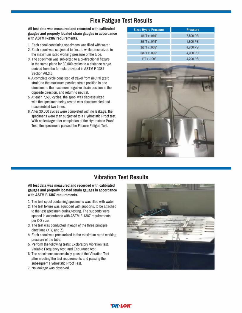
Flex Fatigue Test ResultsAll test data was measured and recorded with calibrated gauges and properly located strain gauges in accordance with ASTM F-1387 requirements.
1. Each spool containing specimens was filled with water.2. Each spool was subjected to flexure while pressurized to
the maximum rated working pressure of the tube.3. The specimen was subjected to a bi-directional flexure
in the same plane for 30,000 cycles to a distance range derived from the formula provided in ASTM F-1387
Section A6.3.5.4. A complete cycle consisted of travel from neutral (zero
strain) to the maximum positive strain position in one direction, to the maximum negative strain position in the opposite direction, and return to neutral.
5. At each 7,500 cycles, the spool was depressurized with the specimen being rested was disassembled and reassembled two times.
6. After 30,000 cycles were completed with no leakage, the specimens were then subjected to a Hydrostatic Proof test. With no leakage after completion of the Hydrostatic Proof Test, the specimens passed the Flexure Fatigue Test.
Vibration Test ResultsAll test data was measured and recorded with calibrated gauges and properly located strain gauges in accordance with ASTM F-1387 requirements.
1. The test spool containing specimens was filled with water.2. The test fixture was equipped with supports, to be attached
to the test specimen during testing. The supports were spaced in accordance with ASTM F-1387 requirements
per OD size.3. The test was conducted in each of the three principle
directions (X,Y, and Z).4. Each spool was pressurized to the maximum rated working
pressure of the tube.5. Perform the following tests: Exploratory Vibration test,
Variable Frequency test, and Endurance test.6. The specimens successfully passed the Vibration Test
after meeting the test requirements and passing the subsequent Hydrostatic Proof Test.
7. No leakage was observed.
Size / Hydro Pressure Pressure
1/4”T x .049” 7,500 PSI
3/8”T x .049” 4,800 PSI
1/2”T x .065” 4,700 PSI
3/4”T x .095” 4,900 PSI
1”T x .109” 4,200 PSI
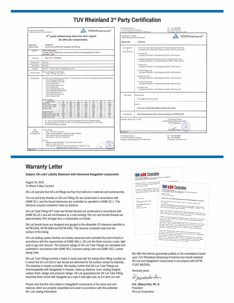
TUV Rheinland 3rd Party Certification
Warranty Letter
August 18, 2016To Whom It May Concern
DK-Lok warrants that DK-Lok fittings are free from defects in materials and workmanship.
The nut and body threads on DK-Lok Fitting OD are constructed in accordance with ASME B1.1 and the thread tolerances are controlled as specified in ASME B1.1. This tolerance ensures consistent make-up distance.
DK-Lok Tube Fitting NPT male and female threads are constructed in accordance with ASME B1.20.1 and are roll threaded by a cold working. DK-Lok cold formed threads are approximately 30% stronger than a comparable cut thread.
DK-Lok ferrule bores are designed and gauged to the allowable OD tolerance specified in ASTM A249, ASTM A269 and ASTM A450. This ensures consistent seal onto thesurface of the tubing.
DK-Lok sealing system finishes are closely measured and controlled Ra (micro-finish) in accordance with the requirements of ASME B46.1. DK-Lok fine finish ensures a leak- tight seal on gas and vacuum. The pressure ratings of DK-Lok Tube Fittings are calculated and published in accordance with ASME B31.3 process piping code and ASME B31.1 power piping code.
DK-Lok Tube Fittings provide a metal to metal seal with the tubing when fitting is pulled up in which the DK-Lok front & rear ferrule are deformed for full surface contact by elasticity. The elasticity is closely controlled. We hereby confirm that DK-Lok Tube Fittings are interchangeable with Swagelok® in threads, make-up distance, bore, sealing integrity, surface finish, design and pressure ratings. DK-Lok guarantees the DK Lok Tube Fitting assembly when mixed with Swagelok as a safe & leak tight seal, as if it were our own.
Please note that this only relates to Swagelok® components of the same size and material, which are properly assembled and used in accordance with the publishedDK- Lok catalog information.
We offer this intermix guarantee publicly to the marketplace based upon TUV Rhineland witnessing of intermix test results between DK-Lok and Swagelok® components in accordance with ASTM F1387-99(2005)
Sincerely yours
H.S. (Steve) Kim, Ph. D.PresidentDK-Lok Corporation
Subject: DK-Lok® Liability Statement with Intermixed Swagelok® components
Mobile, AL Houston, TX Salt Lake City, UT www.dklokusa.com (800) 328-5803