Astah SysML Quick Start Manual for Version...
78
Astah SysML is supported by the Measures to support global technical collaboration grant program. 1 Astah SysML Quick Start Manual for Version 1.4 Copyright© 2016 Change Vision, Inc. All rights reserved. Ver1.4
Transcript of Astah SysML Quick Start Manual for Version...
Astah SysML is supported by the Measures to support global technical collaboration grant program. 1
Astah SysML Quick Start Manual for Version 1.4
Copyright© 2016 Change Vision, Inc. All rights reserved. Ver1.4
Astah SysML is supported by the Measures to support global technical collaboration grant program. 2
Table of Contents
Table of Contents .......................................................................................................... 2
Introduction ................................................................................................................... 6
Setup .............................................................................................................................. 7
System Requirements ........................................................................................................... 7
Download and Install ........................................................................................................... 7
Evaluate ................................................................................................................................ 9
Set up the License after evaluation .................................................................................... 9
Astah SysML Overview ................................................................................................ 10
Overview of Astah Window ............................................................................................... 11
Functionalities on Main Menu .................................................................................... 14
1. Creating a new file ......................................................................................................... 14
2. Printing ............................................................................................................................. 15
3. Line Style ......................................................................................................................... 16
4. Shared Style .................................................................................................................... 17
5. Exporting Images ........................................................................................................... 19
Diagram and Model Elements ................................................................................... 20
Requirement Diagram ....................................................................................................... 20
Model elements on a Requirement Diagram .................................................................. 21
Requirement ........................................................................................................................ 21
TestCase ............................................................................................................................... 22
Derive, Copy, Satisfy, Verify, Refine and Trace ............................................................... 23
Requirement Table ............................................................................................................. 24
How to edit Requirement Table ........................................................................................ 25
Block Definition Diagram ................................................................................................... 27
Model elements on a Block Definition Diagram .............................................................. 27
Block ...................................................................................................................................... 28
InterfaceBlock ...................................................................................................................... 29
ValueType ............................................................................................................................ 30
Unit ......................................................................................................................................... 30
QuantityKind ........................................................................................................................ 31
Internal Block Diagram ...................................................................................................... 32
Model elements on an Internal Block Diagram ............................................................... 32
Part / External Part ............................................................................................................... 32
Nested Part........................................................................................................................... 34
Astah SysML is supported by the Measures to support global technical collaboration grant program. 3
ItemFlow ............................................................................................................................... 35
Connector ............................................................................................................................ 35
Parametric Diagram ........................................................................................................... 36
Model elements on a Parametric Diagram ..................................................................... 37
Constraint Property ............................................................................................................. 37
Binding Connector .............................................................................................................. 38
Constraint Parameter ......................................................................................................... 39
Value Property ..................................................................................................................... 39
UseCase Diagram .............................................................................................................. 41
Model elements on a UseCase Diagram ......................................................................... 41
Actor/BusinessActor ............................................................................................................ 41
UseCase/BusinessUseCase ................................................................................................. 42
Include .................................................................................................................................. 43
Extend ................................................................................................................................... 43
Extension Point ..................................................................................................................... 44
UseCase Description ........................................................................................................... 44
Statemachine Diagram ..................................................................................................... 46
Model elements on a Statemachine Diagram ................................................................ 46
Initial Pseudo States / Final States .................................................................................... 46
States ..................................................................................................................................... 46
Transitions .............................................................................................................................. 47
Shallow History Pseudo State and Deep History Pseudo State ..................................... 47
Junction Pseudostates ........................................................................................................ 47
Choices Pseudostates ........................................................................................................ 48
Fork Pseudostates and Join Pseudostates ....................................................................... 48
EntryPoint and ExitPoint ...................................................................................................... 48
Submachine States ............................................................................................................. 49
StubStates in Submachine States ...................................................................................... 49
Activity Diagram ................................................................................................................ 50
Model elements on an Activity Diagram ......................................................................... 50
Partitions ............................................................................................................................... 50
Initial Nodes .......................................................................................................................... 51
Action.................................................................................................................................... 52
CallBehaviorAction ............................................................................................................. 52
Activity Final ......................................................................................................................... 52
Flow Final Nodes .................................................................................................................. 53
SendSignal Actions and AcceptEvent Actions ............................................................... 53
AcceptTimeEventActions .................................................................................................. 53
Astah SysML is supported by the Measures to support global technical collaboration grant program. 4
Control Flow/Object Flow .................................................................................................. 53
Merge Nodes/Decision Nodes .......................................................................................... 53
Fork Nodes/Join Nodes ...................................................................................................... 54
Parameter Nodes ................................................................................................................ 54
InputPins/OutputPins ........................................................................................................... 54
Object Nodes ...................................................................................................................... 54
Process .................................................................................................................................. 55
Connector ............................................................................................................................ 55
Dependencies ..................................................................................................................... 55
Sequence Diagram ............................................................................................................ 55
Model elements on a Sequence Diagram ....................................................................... 56
Lifeline ................................................................................................................................... 56
Synchronous Messages ...................................................................................................... 56
Asynchronous Messages .................................................................................................... 57
Found Messages .................................................................................................................. 57
Lost Messages ...................................................................................................................... 58
Gate ...................................................................................................................................... 58
“Create” Messages ............................................................................................................ 59
“Destroy” Message ............................................................................................................. 59
“Reply” Message ................................................................................................................. 59
Stop ....................................................................................................................................... 60
Duration Constraint and Time Constraint ........................................................................ 60
Combined Fragment .......................................................................................................... 61
Interaction Use ..................................................................................................................... 62
State Invariant ...................................................................................................................... 62
Mind map ........................................................................................................................... 63
Tool Buttons .......................................................................................................................... 64
Topics .................................................................................................................................... 64
Floating Topic....................................................................................................................... 65
Edges .................................................................................................................................... 67
Link between Topics ........................................................................................................... 67
Boundary .............................................................................................................................. 67
Common Model Elements ......................................................................................... 67
Port / Proxy Port / Full Port .................................................................................................. 67
Interface ............................................................................................................................... 69
Provided Interface/Required Interface ........................................................................... 69
Association ........................................................................................................................... 70
Nest ....................................................................................................................................... 71
Astah SysML is supported by the Measures to support global technical collaboration grant program. 5
Realization/Dependency/Nest ......................................................................................... 71
Note and Note Anchor ...................................................................................................... 71
Text ........................................................................................................................................ 71
General-purpose object .................................................................................................... 72
Other options and settings ......................................................................................... 72
Tool Menu ............................................................................................................................. 72
1. Insert Images .................................................................................................................... 73
2. Lock on the selected model ......................................................................................... 73
3. Set line ends in the center of model elements ........................................................... 73
4. Line Style ........................................................................................................................... 74
5. Suggest Feature .............................................................................................................. 74
System Properties ............................................................................................................... 75
Font Setting ......................................................................................................................... 75
Visibility Setting ................................................................................................................... 75
Copy and Paste .asml files ................................................................................................ 77
Astah SysML API .................................................................................................................. 77
Send us Feedback ...................................................................................................... 78
Astah SysML is supported by the Measures to support global technical collaboration grant program. 6
Introduction
Thank you for downloading Astah SysML.
This Quick Start Manual briefly explains all the functionalities Astah SysML supports. If
you have any questions or feedback, please send them over to us.
Email: [email protected]
Contact through Website: http://astah.net/editions/sysml/feedback
The contents of this quick start guide may be changed without prior notice. The following trademarks and copyright apply to the software that is provided with this manual. Copyright© 2014 Change Vision, Inc. All rights reserved. UML, Unified Modeling Language, OMG SysML are all registered trademarks or trademarks of Object Management Group, Inc. in the United States and/or other countries. Java is registered trademarks of Oracle and/or its affiliates. Mind Map is a registered trademark of the Buzan Organization Ltd. If other trademarked product names or company names appear, they are only used as names. Symbols, such as ™, ®, ©, are omitted in the main contents.
Astah SysML is supported by the Measures to support global technical collaboration grant program. 7
Setup
In order to set up Astah SysML, please make sure that your machine meets the System
requirements below.
System Requirements
Your environment needs to meet the system requirements described on the page below.
http://astah.net/requirements#sysml-requirements
Download and Install
1. Download Astah SysML from our website: http://astah.net/editions/sysml/download
2. After downloading Astah SysML, run the setup and follow the given instructions.

Astah SysML is supported by the Measures to support global technical collaboration grant program. 8
3. Once you have completed the installation, you can run Astah SysML from Application menu or double-click the application icon of Astah SysML.
4. Once you start Astah SysML, a dialog appears to tell the date you are able to try out Astah SysML until.

Astah SysML is supported by the Measures to support global technical collaboration grant program. 9
5. Click [OK] to start
For running Astah on Linux, please refer to the page : How to run Astah on Linux
If you already have a license, please go to Setting up the license.
Evaluate
From the day you install Astah SysML, you can use Astah SysML for 20 days without
setting any licenses. In order to extend your evaluation period, go to [Tool] – [License]
and click [Evaluation License] to apply one.
Set up the License after evaluation
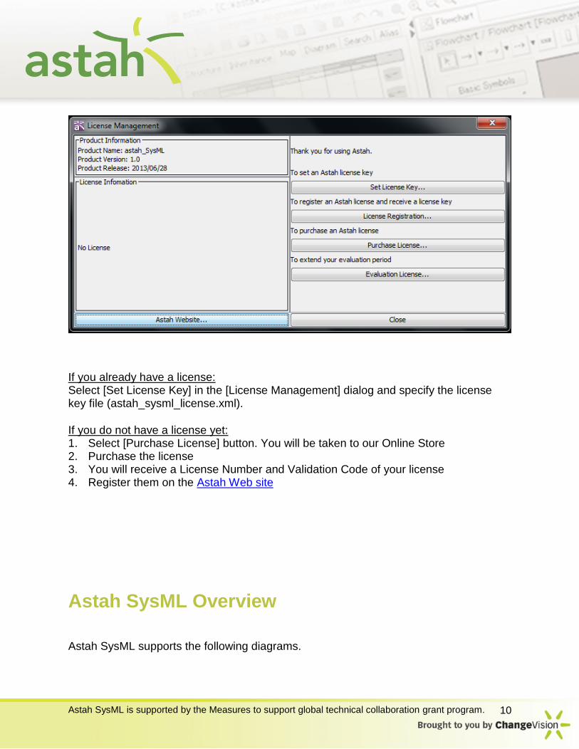
After the 20 day trial and the license is not set in Astah, the “License Management”
dialog comes up when starting Astah.
Astah SysML is supported by the Measures to support global technical collaboration grant program. 10
If you already have a license: Select [Set License Key] in the [License Management] dialog and specify the license key file (astah_sysml_license.xml).
If you do not have a license yet: 1. Select [Purchase License] button. You will be taken to our Online Store 2. Purchase the license 3. You will receive a License Number and Validation Code of your license 4. Register them on the Astah Web site
Astah SysML Overview
Astah SysML supports the following diagrams.

Astah SysML is supported by the Measures to support global technical collaboration grant program. 11
SysML
- Block Definition Diagram
- Internal Block Diagram
- Parametric Diagram
- Requirement Diagram/Table
SysML/UML
- UseCase Diagram
- Activity Diagram
- Statemachine Diagram
- Sequence Diagram
Other - Mind Map
Overview of Astah Window
Astah consists of main 4 views as below.
1: Management View
It has a menu bar and icons of frequently used menu options

Astah SysML is supported by the Measures to support global technical collaboration grant program. 12
2: Project View
It consists the following five tabs.
Structure: It shows all the diagrams and main models in the tree so that you can see
the model structure in the tree view. You can also add new diagrams or models from
this view.
Inheritance: It shows the inheritance tree of the models especially Blocks and
Interfaces. Simply select the model you want to see its inheritance in the diagram. You
can also add diagrams or models from this view too.
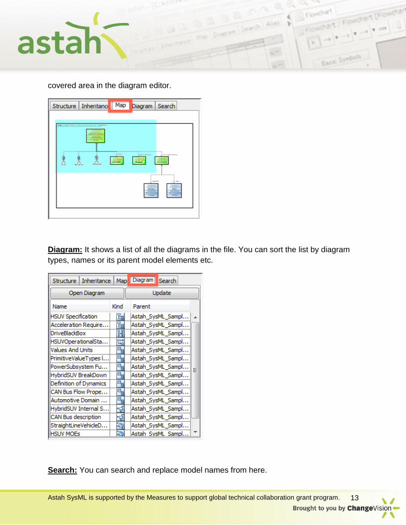
Map: You can control and adjust the area of diagram to show in the diagram editor in
this view. This view is very useful when you have a large diagram, you can select
certain area you want to see enlarged in blue rectangle, and then Astah shows the
Astah SysML is supported by the Measures to support global technical collaboration grant program. 13
covered area in the diagram editor.
Diagram: It shows a list of all the diagrams in the file. You can sort the list by diagram
types, names or its parent model elements etc.
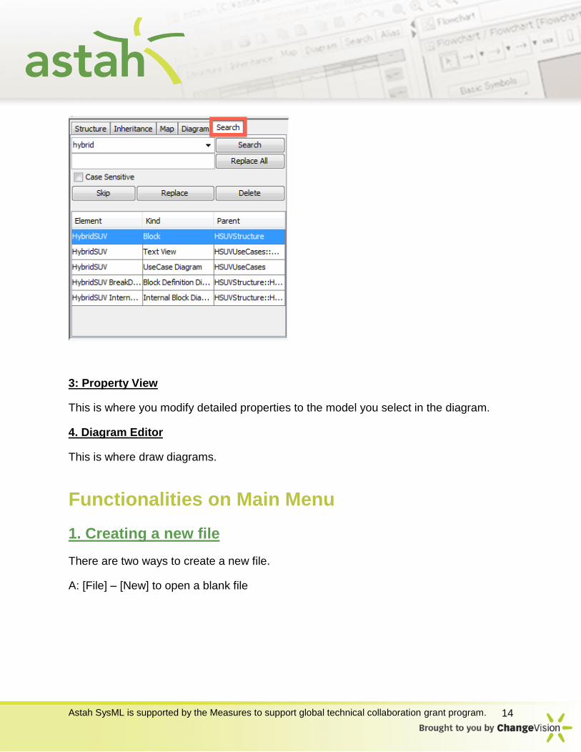
Search: You can search and replace model names from here.
Astah SysML is supported by the Measures to support global technical collaboration grant program. 14
3: Property View
This is where you modify detailed properties to the model you select in the diagram.
4. Diagram Editor
This is where draw diagrams.
Functionalities on Main Menu
1. Creating a new file
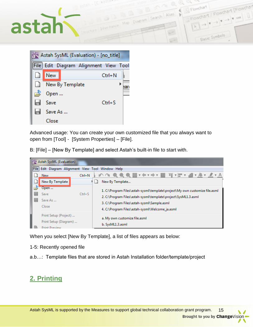
There are two ways to create a new file.
A: [File] – [New] to open a blank file
Astah SysML is supported by the Measures to support global technical collaboration grant program. 15
Advanced usage: You can create your own customized file that you always want to
open from [Tool] - [System Properties] – [File].
B: [File] – [New By Template] and select Astah’s built-in file to start with.
When you select [New By Template], a list of files appears as below:
1-5: Recently opened file
a.b…: Template files that are stored in Astah Installation folder/template/project
2. Printing

Astah SysML is supported by the Measures to support global technical collaboration grant program. 16
You can configure the printing preference per project file that applies for all the
diagrams or per each diagram or per diagram individually.
Print Setup (Project) : [File] – [Print Setup (Project)]
You can set your printing preference for all the diagrams at once in this dialog.
Print Setup (Diagram) : [File] – [Print Setup (Diagram)]
You can set your printing preference for each diagram you are currently opening. To
allow yourself to apply the print setting to certain diagrams individually, check off the
[Print by using the print setting for the project] and then set it up.
3. Line Style
Astah SysML is supported by the Measures to support global technical collaboration grant program. 17
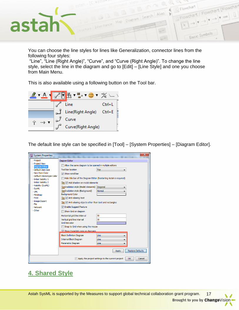
You can choose the line styles for lines like Generalization, connector lines from the following four styles: “Line”, “Line (Right Angle)”, “Curve”, and “Curve (Right Angle)”. To change the line style, select the line in the diagram and go to [Edit] – [Line Style] and one you choose from Main Menu. This is also available using a following button on the Tool bar.
The default line style can be specified in [Tool] – [System Properties] – [Diagram Editor].
4. Shared Style
Astah SysML is supported by the Measures to support global technical collaboration grant program. 18
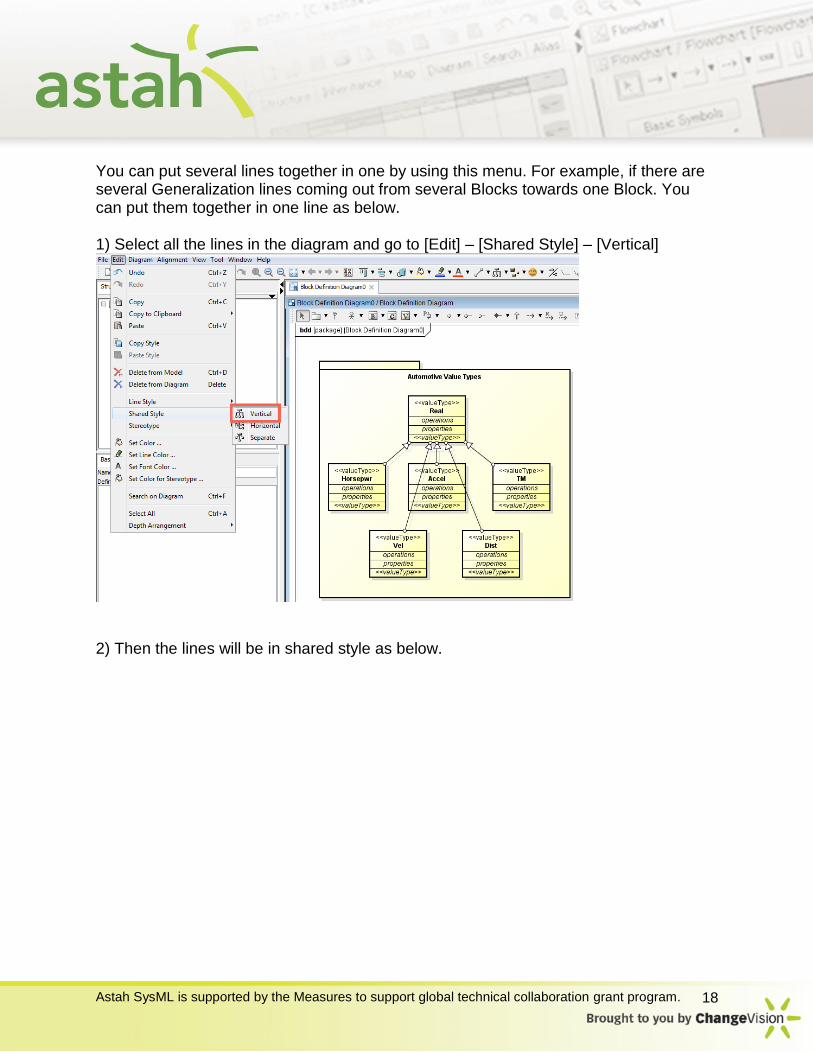
You can put several lines together in one by using this menu. For example, if there are several Generalization lines coming out from several Blocks towards one Block. You can put them together in one line as below. 1) Select all the lines in the diagram and go to [Edit] – [Shared Style] – [Vertical]
2) Then the lines will be in shared style as below.

Astah SysML is supported by the Measures to support global technical collaboration grant program. 19
5. Exporting Images
You can export diagram(s) in PNG/JPEG/EMF/SVG format files from [Tool] – [Export
Image].

Astah SysML is supported by the Measures to support global technical collaboration grant program. 20
Diagram and Model Elements
Requirement Diagram
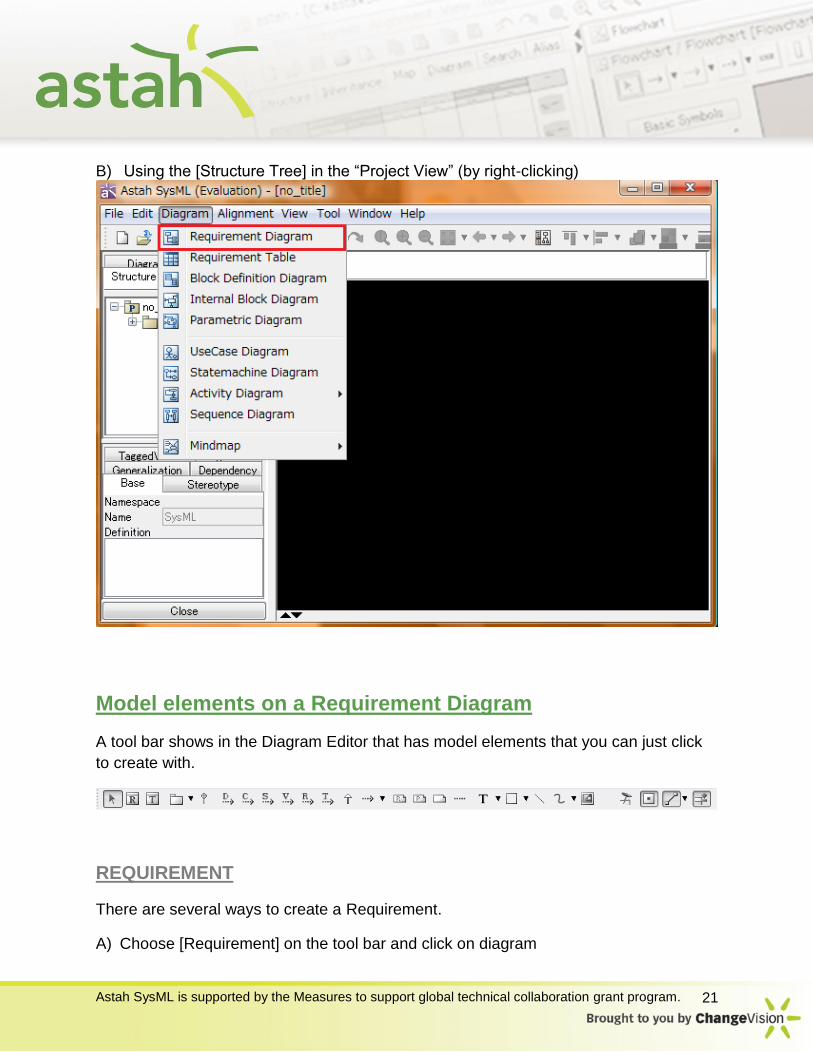
There are several ways to create a Requirement Diagram. A) Using [Diagram]-[Requirement Diagram] in the Main Menu
Astah SysML is supported by the Measures to support global technical collaboration grant program. 21
B) Using the [Structure Tree] in the “Project View” (by right-clicking)
Model elements on a Requirement Diagram
A tool bar shows in the Diagram Editor that has model elements that you can just click
to create with.
REQUIREMENT
There are several ways to create a Requirement.
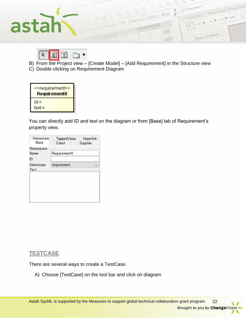
A) Choose [Requirement] on the tool bar and click on diagram
Astah SysML is supported by the Measures to support global technical collaboration grant program. 22
B) From the Project view – [Create Model] – [Add Requirement] in the Structure view C) Double clicking on Requirement Diagram
You can directly add ID and text on the diagram or from [Base] tab of Requirement’s
property view.
TESTCASE
There are several ways to create a TestCase.
A) Choose [TestCase] on the tool bar and click on diagram

Astah SysML is supported by the Measures to support global technical collaboration grant program. 23
B) From the Project view – [Create Model] – [Add TestCase] in the Structure view
To add an ID, go to [Base] tab of TestCase in the Property View.
DERIVE, COPY, SATISFY, VERIFY, REFINE AND TRACE
There are several ways to create a Derive, Copy, Satisfy, Verify, Refine and Trace.
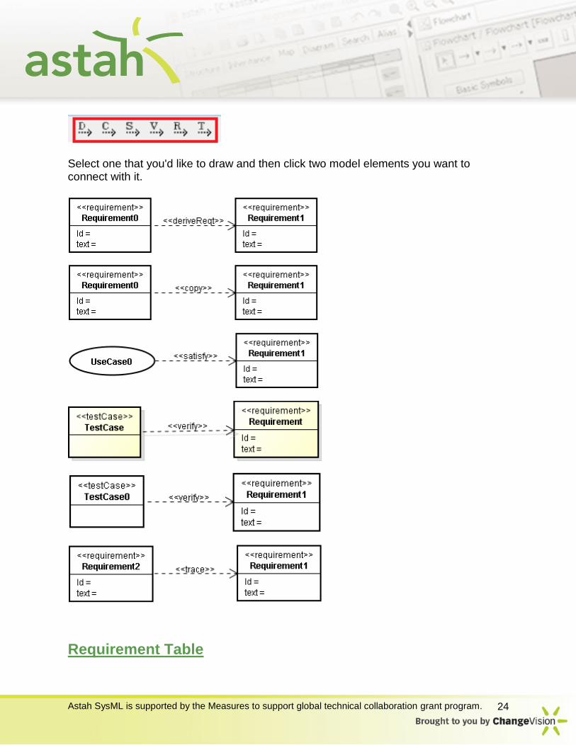
Astah SysML is supported by the Measures to support global technical collaboration grant program. 24
Select one that you'd like to draw and then click two model elements you want to connect with it.
Requirement Table
Astah SysML is supported by the Measures to support global technical collaboration grant program. 25
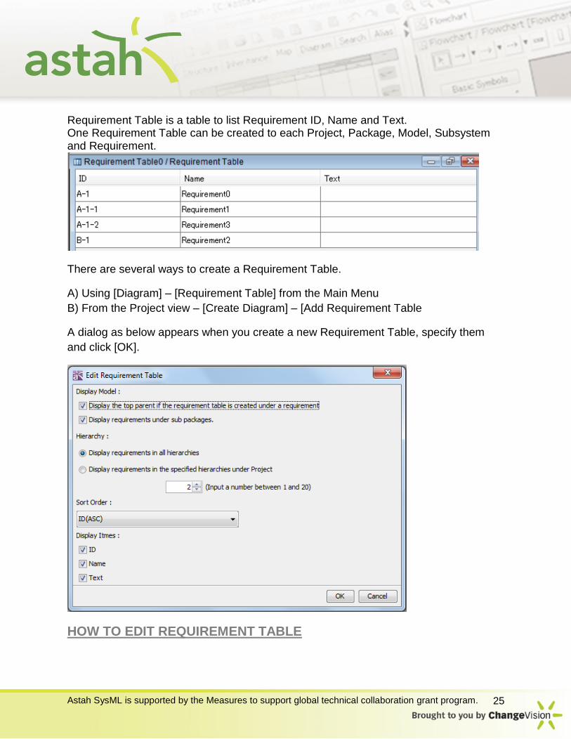
Requirement Table is a table to list Requirement ID, Name and Text. One Requirement Table can be created to each Project, Package, Model, Subsystem and Requirement.
There are several ways to create a Requirement Table.
A) Using [Diagram] – [Requirement Table] from the Main Menu
B) From the Project view – [Create Diagram] – [Add Requirement Table
A dialog as below appears when you create a new Requirement Table, specify them
and click [OK].
HOW TO EDIT REQUIREMENT TABLE
Astah SysML is supported by the Measures to support global technical collaboration grant program. 26
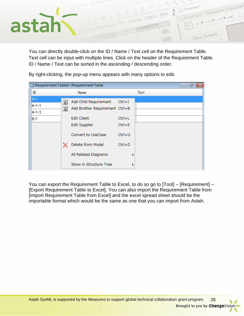
You can directly double-click on the ID / Name / Text cell on the Requirement Table.
Text cell can be input with multiple lines. Click on the header of the Requirement Table.
ID / Name / Text can be sorted in the ascending / descending order.
By right-clicking, the pop-up menu appears with many options to edit.
You can export the Requirement Table to Excel, to do so go to [Tool] – [Requirement] – [Export Requirement Table to Excel]. You can also import the Requirement Table from [Import Requirement Table from Excel] and the excel spread sheet should be the importable format which would be the same as one that you can import from Astah.
Astah SysML is supported by the Measures to support global technical collaboration grant program. 27
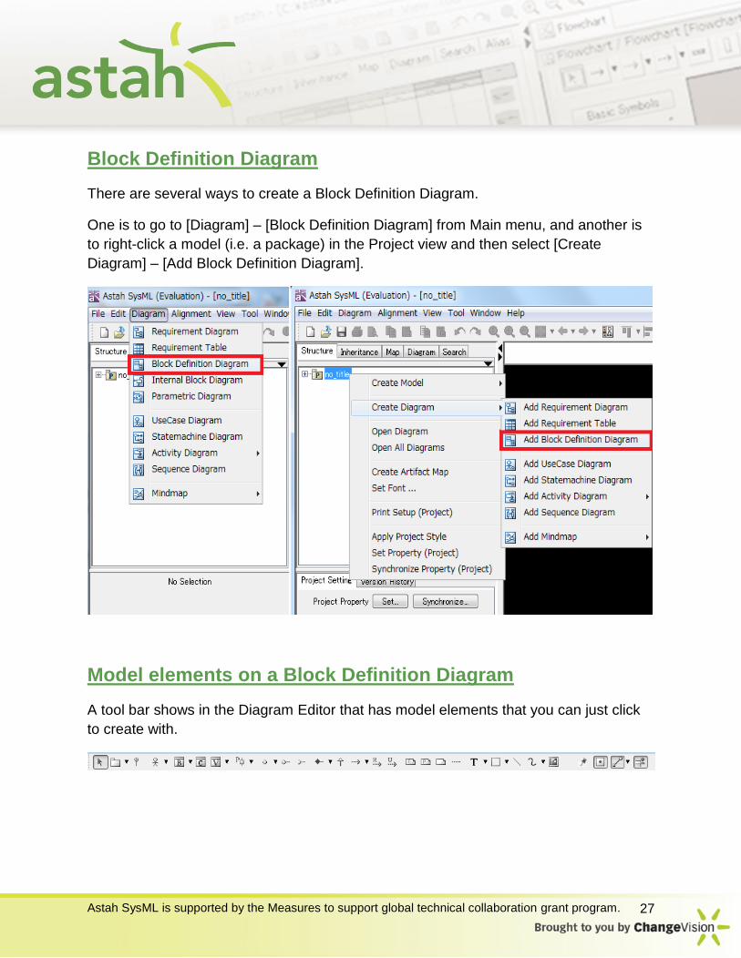
Block Definition Diagram
There are several ways to create a Block Definition Diagram.
One is to go to [Diagram] – [Block Definition Diagram] from Main menu, and another is
to right-click a model (i.e. a package) in the Project view and then select [Create
Diagram] – [Add Block Definition Diagram].
Model elements on a Block Definition Diagram
A tool bar shows in the Diagram Editor that has model elements that you can just click
to create with.

Astah SysML is supported by the Measures to support global technical collaboration grant program. 28
BLOCK
There are several ways to create a Block.
A) Double-click somewhere on the Block Definition Diagram B) Select [Block] from tool bar and then click on the Block Definition Diagram
C) In the Structure Tree, right click some model element and then select [Create Model]
- [Add Block] from its Pop-up menu and then drag and drop it in the diagram.
To add properties to the Block, directly click the blue cross (Called “Suggest Feature”)
that is displayed at each compartment and then type in, or you could right-click Block
and add/delete the properties.

Astah SysML is supported by the Measures to support global technical collaboration grant program. 29
Or you could use the property view (The left bottom pane). Select the Block in the
diagram or Structure tree and then go to the Property View. Switch tabs to choose the
properties you want to add/modify of.
INTERFACEBLOCK
There are two ways to create an Interface Block.
A) Select [InterfaceBlock] from tool bar and then click on the Block Definition Diagram
B) In the Structure Tree, right click some model element (i.e. a package) and then select
[Create Model] – [InterfaceBlock] from its Pop-up menu and then drag and drop it in the
diagram.
You can add/modify the properties in a same way as Block.
Astah SysML is supported by the Measures to support global technical collaboration grant program. 30
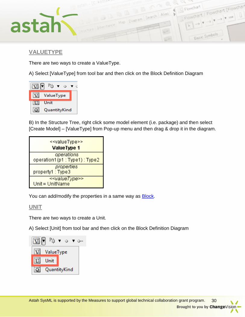
VALUETYPE
There are two ways to create a ValueType.
A) Select [ValueType] from tool bar and then click on the Block Definition Diagram
B) In the Structure Tree, right click some model element (i.e. package) and then select
[Create Model] – [ValueType] from Pop-up menu and then drag & drop it in the diagram.
You can add/modify the properties in a same way as Block.
UNIT
There are two ways to create a Unit.
A) Select [Unit] from tool bar and then click on the Block Definition Diagram
Astah SysML is supported by the Measures to support global technical collaboration grant program. 31
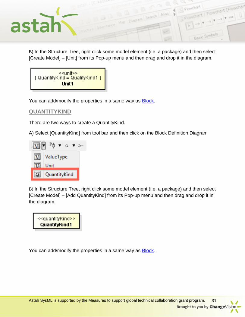
B) In the Structure Tree, right click some model element (i.e. a package) and then select
[Create Model] – [Unit] from its Pop-up menu and then drag and drop it in the diagram.
You can add/modify the properties in a same way as Block.
QUANTITYKIND
There are two ways to create a QuantityKind.
A) Select [QuantityKind] from tool bar and then click on the Block Definition Diagram
B) In the Structure Tree, right click some model element (i.e. a package) and then select
[Create Model] – [Add QuantityKind] from its Pop-up menu and then drag and drop it in
the diagram.
You can add/modify the properties in a same way as Block.
Astah SysML is supported by the Measures to support global technical collaboration grant program. 32
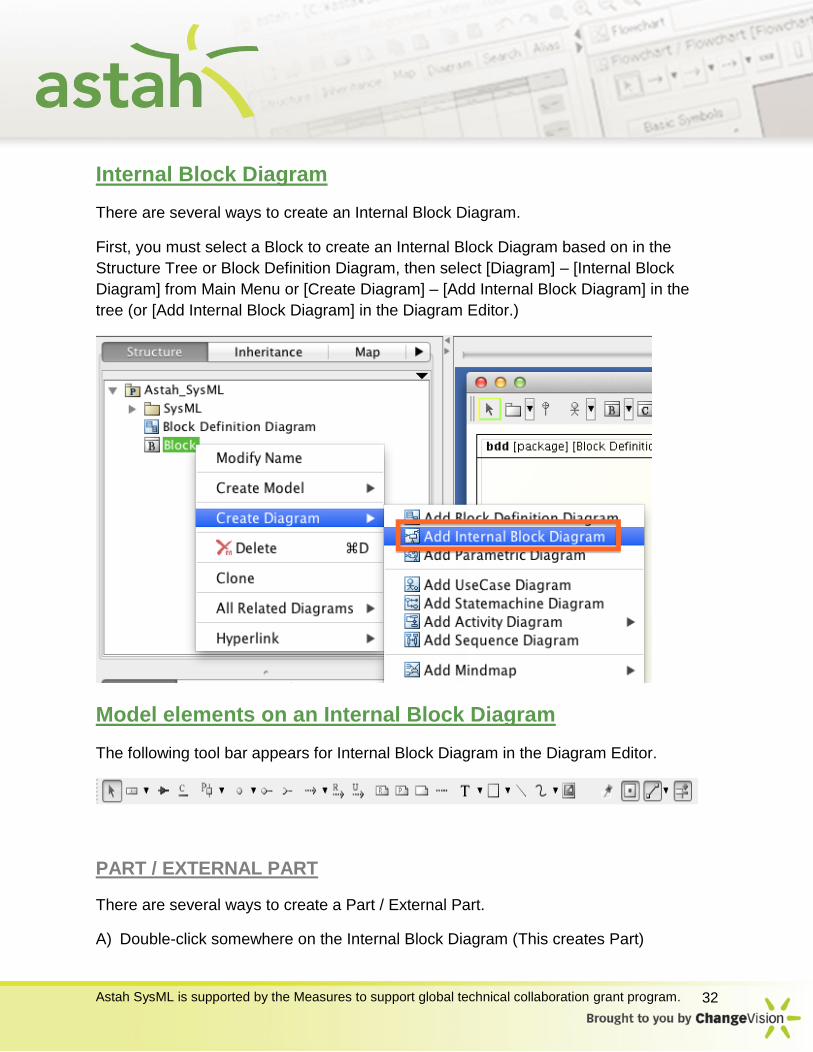
Internal Block Diagram
There are several ways to create an Internal Block Diagram.
First, you must select a Block to create an Internal Block Diagram based on in the
Structure Tree or Block Definition Diagram, then select [Diagram] – [Internal Block
Diagram] from Main Menu or [Create Diagram] – [Add Internal Block Diagram] in the
tree (or [Add Internal Block Diagram] in the Diagram Editor.)
Model elements on an Internal Block Diagram
The following tool bar appears for Internal Block Diagram in the Diagram Editor.
PART / EXTERNAL PART
There are several ways to create a Part / External Part.
A) Double-click somewhere on the Internal Block Diagram (This creates Part)
Astah SysML is supported by the Measures to support global technical collaboration grant program. 33
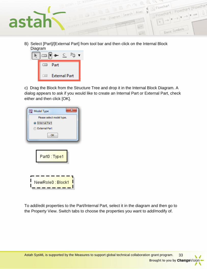
B) Select [Part]/[External Part] from tool bar and then click on the Internal Block Diagram
c) Drag the Block from the Structure Tree and drop it in the Internal Block Diagram. A
dialog appears to ask if you would like to create an Internal Part or External Part, check
either and then click [OK].
To add/edit properties to the Part/Internal Part, select it in the diagram and then go to
the Property View. Switch tabs to choose the properties you want to add/modify of.
Astah SysML is supported by the Measures to support global technical collaboration grant program. 34
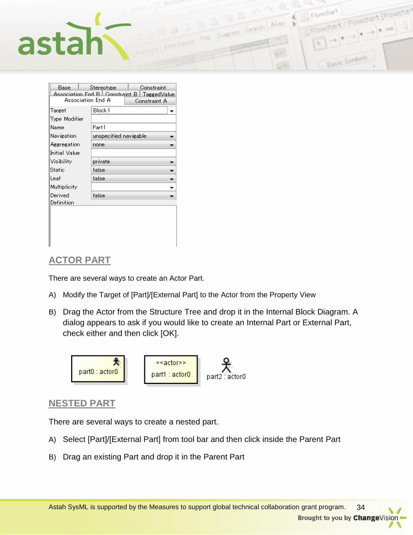
ACTOR PART
There are several ways to create an Actor Part.
A) Modify the Target of [Part]/[External Part] to the Actor from the Property View
B) Drag the Actor from the Structure Tree and drop it in the Internal Block Diagram. A
dialog appears to ask if you would like to create an Internal Part or External Part,
check either and then click [OK].
NESTED PART
There are several ways to create a nested part.
A) Select [Part]/[External Part] from tool bar and then click inside the Parent Part
B) Drag an existing Part and drop it in the Parent Part
Astah SysML is supported by the Measures to support global technical collaboration grant program. 35
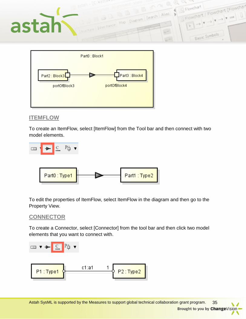
ITEMFLOW
To create an ItemFlow, select [ItemFlow] from the Tool bar and then connect with two
model elements.
To edit the properties of ItemFlow, select ItemFlow in the diagram and then go to the
Property View.
CONNECTOR
To create a Connector, select [Connector] from the tool bar and then click two model
elements that you want to connect with.

Astah SysML is supported by the Measures to support global technical collaboration grant program. 36
To edit the properties of Connector, select Connector in the diagram and then go to the
Property View. Switch tabs to choose the properties you want to add/modify of.
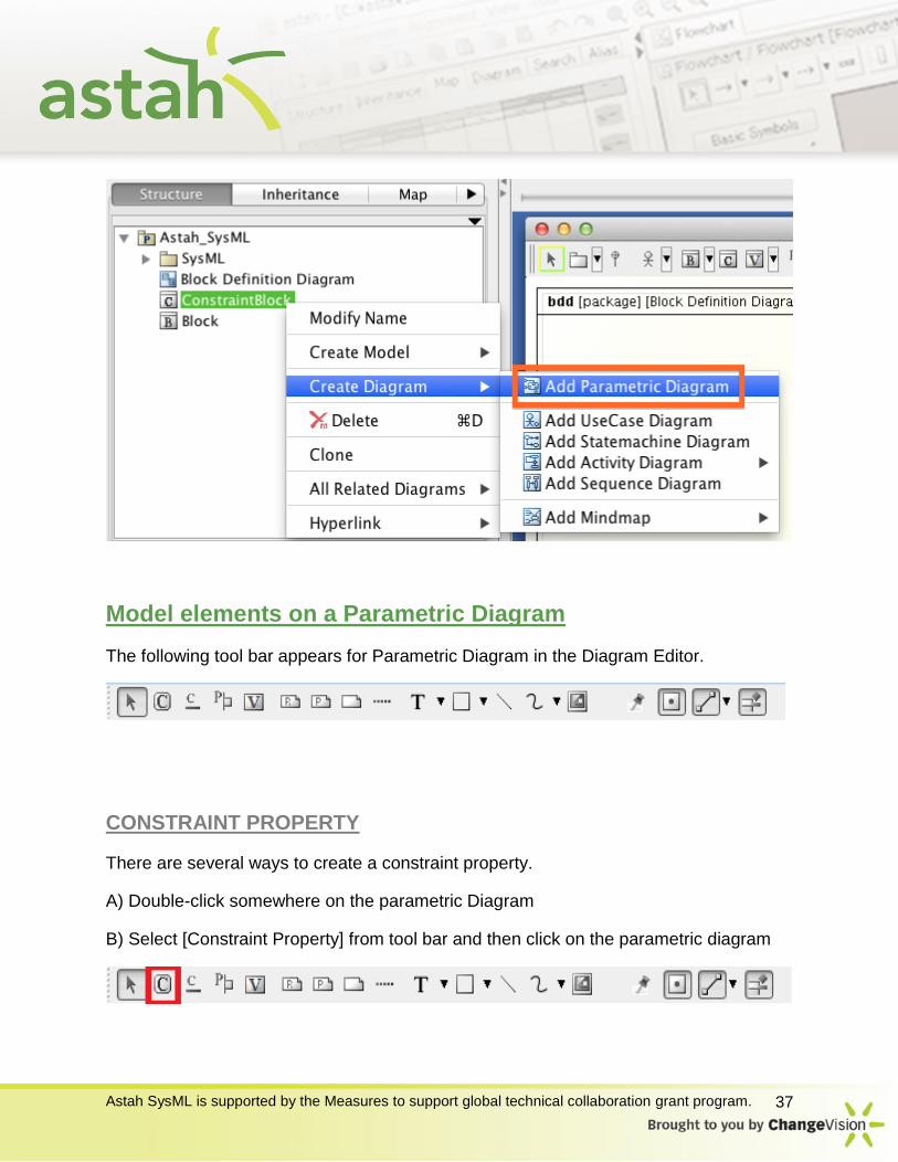
Parametric Diagram
There are several ways to create a Parametric Diagram.
First, you must select a Block or a Constraint Block on the Structure Tree or a
Parametric Diagram, then select [Diagram] – [Parametric Diagram] from Main Menu or
[Create Diagram] – [Add Parametric Diagram] in the tree (or [Add Parametric Diagram]
popup menu item in the Diagram Editor.)
Astah SysML is supported by the Measures to support global technical collaboration grant program. 37
Model elements on a Parametric Diagram
The following tool bar appears for Parametric Diagram in the Diagram Editor.
CONSTRAINT PROPERTY
There are several ways to create a constraint property.
A) Double-click somewhere on the parametric Diagram
B) Select [Constraint Property] from tool bar and then click on the parametric diagram

Astah SysML is supported by the Measures to support global technical collaboration grant program. 38
To edit properties of the constraint property, select it in the diagram and then go to the
Property View.
BINDING CONNECTOR
To create a binding connector, select [Binding Connector] from the Tool bar and then
connect with two constraint parameters or with a constraint parameter and a value
property
To edit the properties of binding connector, select binding connector in the diagram and
then go to the Property View.

Astah SysML is supported by the Measures to support global technical collaboration grant program. 39
CONSTRAINT PARAMETER
To create a constraint parameter, select [constraint parameter] from the tool bar and
then click a constraint property that you want to add to.
Constraint Parameters are the parameters of the ConstraintBlock on the Block
Definition Diagram.
To edit the properties of constraint parameter, select constraint parameter in the
diagram and then go to the Property View.
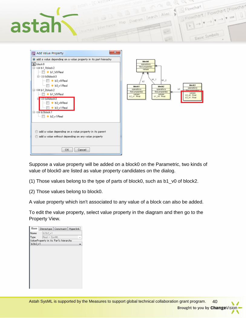
VALUE PROPERTY
To create a Value Property, select [Value Property] from the tool bar and then click
parametric diagram.
When creating a new value Property, a dialog on the left appears and you will choose
the Value Property in the diagram and then click [OK].
Astah SysML is supported by the Measures to support global technical collaboration grant program. 40
Suppose a value property will be added on a block0 on the Parametric, two kinds of
value of block0 are listed as value property candidates on the dialog.
(1) Those values belong to the type of parts of block0, such as b1_v0 of block2.
(2) Those values belong to block0.
A value property which isn't associated to any value of a block can also be added.
To edit the value property, select value property in the diagram and then go to the
Property View.
Astah SysML is supported by the Measures to support global technical collaboration grant program. 41
UseCase Diagram
There are several ways to create a UseCase Diagram.
One is to go to [Diagram] – [UseCase Diagram] from Main menu, and another is to
right-click a model (i.e. a package) in the Project view and then select [Create Diagram]
– [Add UseCase Diagram].
Model elements on a UseCase Diagram
A tool bar shows in the Diagram Editor that has model elements that you can just click to create with.
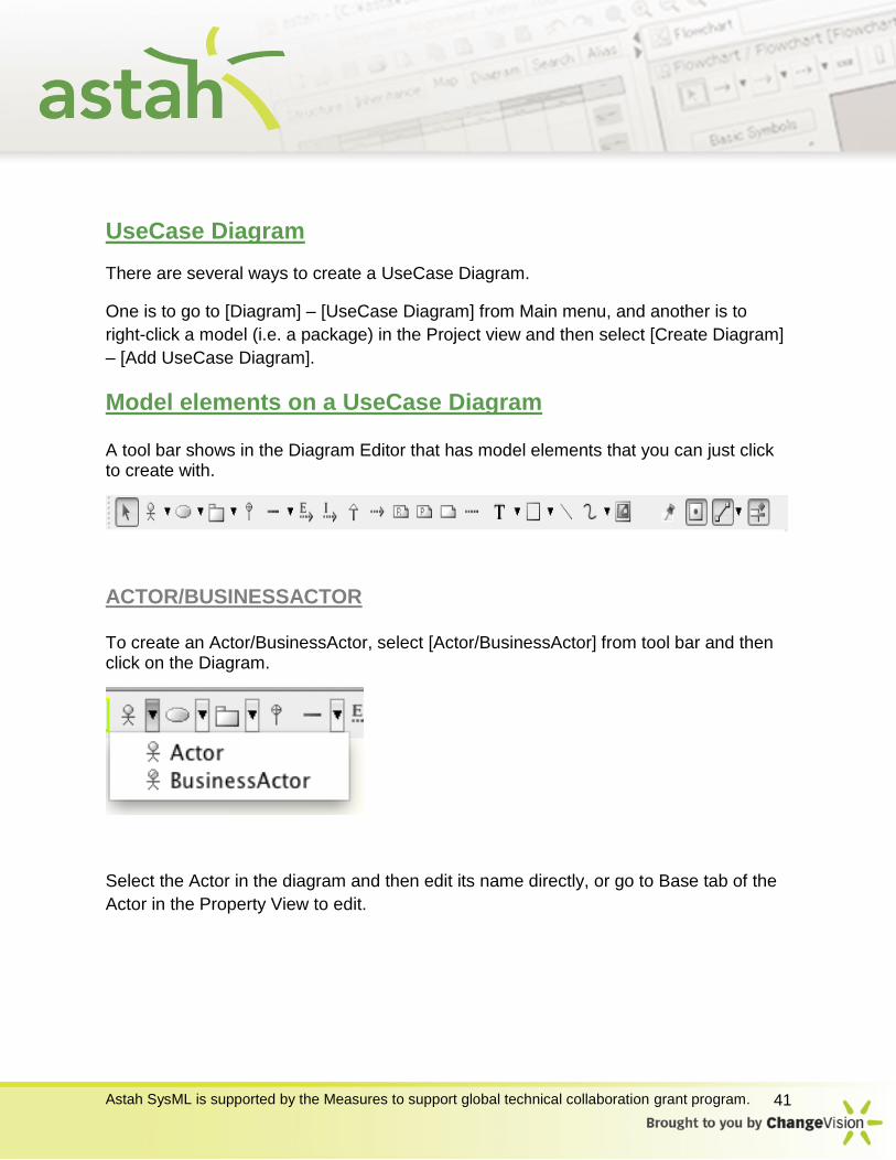
ACTOR/BUSINESSACTOR
To create an Actor/BusinessActor, select [Actor/BusinessActor] from tool bar and then click on the Diagram.
Select the Actor in the diagram and then edit its name directly, or go to Base tab of the
Actor in the Property View to edit.
Astah SysML is supported by the Measures to support global technical collaboration grant program. 42
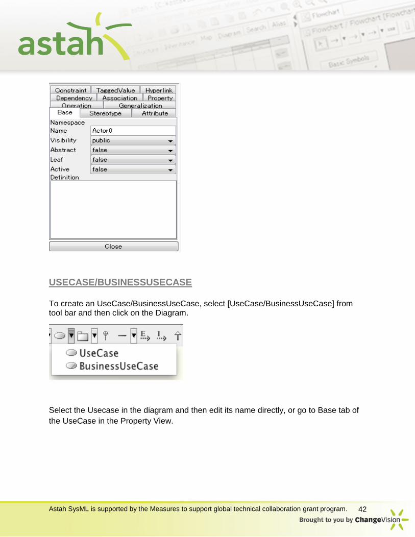
USECASE/BUSINESSUSECASE
To create an UseCase/BusinessUseCase, select [UseCase/BusinessUseCase] from tool bar and then click on the Diagram.
Select the Usecase in the diagram and then edit its name directly, or go to Base tab of
the UseCase in the Property View.

Astah SysML is supported by the Measures to support global technical collaboration grant program. 43
INCLUDE
To create an Include, select it on the tool bar and click the two model elements to connect.
EXTEND
To create an extend, select it on the tool bar and click the two model elements to connect.
Notes about Extends and Includes Extends are not the same as Dependencies with the Stereotype <<extend>>. Similarly
and Includes are not the same as Dependencies with the Stereotype<<include>>.
Astah SysML is supported by the Measures to support global technical collaboration grant program. 44
Dependencies with “extend” or “include” as their Stereotypes are not recognized as
Extends or Includes by Astah.
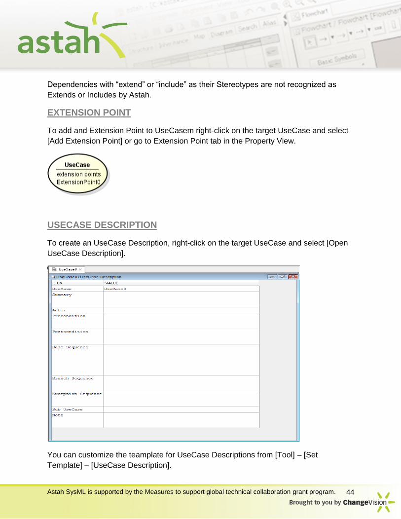
EXTENSION POINT
To add and Extension Point to UseCasem right-click on the target UseCase and select
[Add Extension Point] or go to Extension Point tab in the Property View.
USECASE DESCRIPTION
To create an UseCase Description, right-click on the target UseCase and select [Open
UseCase Description].
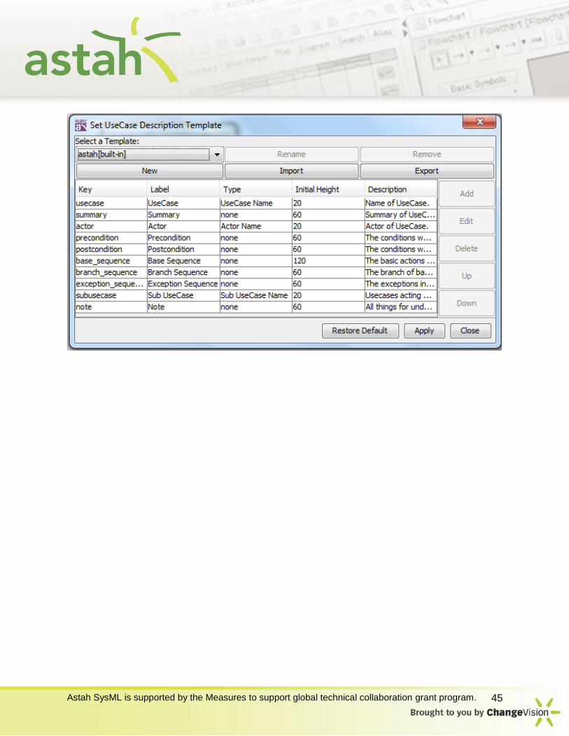
You can customize the teamplate for UseCase Descriptions from [Tool] – [Set
Template] – [UseCase Description].
Astah SysML is supported by the Measures to support global technical collaboration grant program. 45
Astah SysML is supported by the Measures to support global technical collaboration grant program. 46
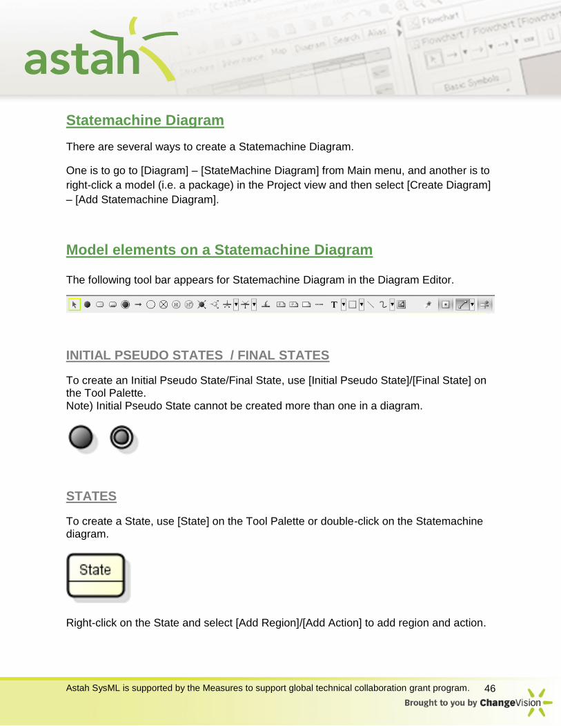
Statemachine Diagram
There are several ways to create a Statemachine Diagram.
One is to go to [Diagram] – [StateMachine Diagram] from Main menu, and another is to
right-click a model (i.e. a package) in the Project view and then select [Create Diagram]
– [Add Statemachine Diagram].
Model elements on a Statemachine Diagram
The following tool bar appears for Statemachine Diagram in the Diagram Editor.
INITIAL PSEUDO STATES / FINAL STATES
To create an Initial Pseudo State/Final State, use [Initial Pseudo State]/[Final State] on the Tool Palette. Note) Initial Pseudo State cannot be created more than one in a diagram.
STATES
To create a State, use [State] on the Tool Palette or double-click on the Statemachine diagram.
Right-click on the State and select [Add Region]/[Add Action] to add region and action.
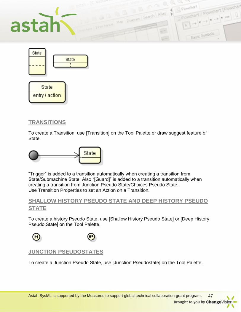
Astah SysML is supported by the Measures to support global technical collaboration grant program. 47
TRANSITIONS
To create a Transition, use [Transition] on the Tool Palette or draw suggest feature of State.
“Trigger” is added to a transition automatically when creating a transition from State/Submachine State. Also “[Guard]” is added to a transition automatically when creating a transition from Junction Pseudo State/Choices Pseudo State. Use Transition Properties to set an Action on a Transition.
SHALLOW HISTORY PSEUDO STATE AND DEEP HISTORY PSEUDO
STATE
To create a history Pseudo State, use [Shallow History Pseudo State] or [Deep History Pseudo State] on the Tool Palette.
JUNCTION PSEUDOSTATES
To create a Junction Pseudo State, use [Junction Pseudostate] on the Tool Palette.
Astah SysML is supported by the Measures to support global technical collaboration grant program. 48
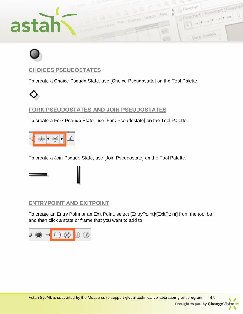
CHOICES PSEUDOSTATES
To create a Choice Pseudo State, use [Choice Pseudostate] on the Tool Palette.
FORK PSEUDOSTATES AND JOIN PSEUDOSTATES
To create a Fork Pseudo State, use [Fork Pseudostate] on the Tool Palette.
To create a Join Pseudo State, use [Join Pseudostate] on the Tool Palette.
ENTRYPOINT AND EXITPOINT
To create an Entry Point or an Exit Point, select [EntryPoint]/[ExitPoint] from the tool bar
and then click a state or frame that you want to add to.
Astah SysML is supported by the Measures to support global technical collaboration grant program. 49
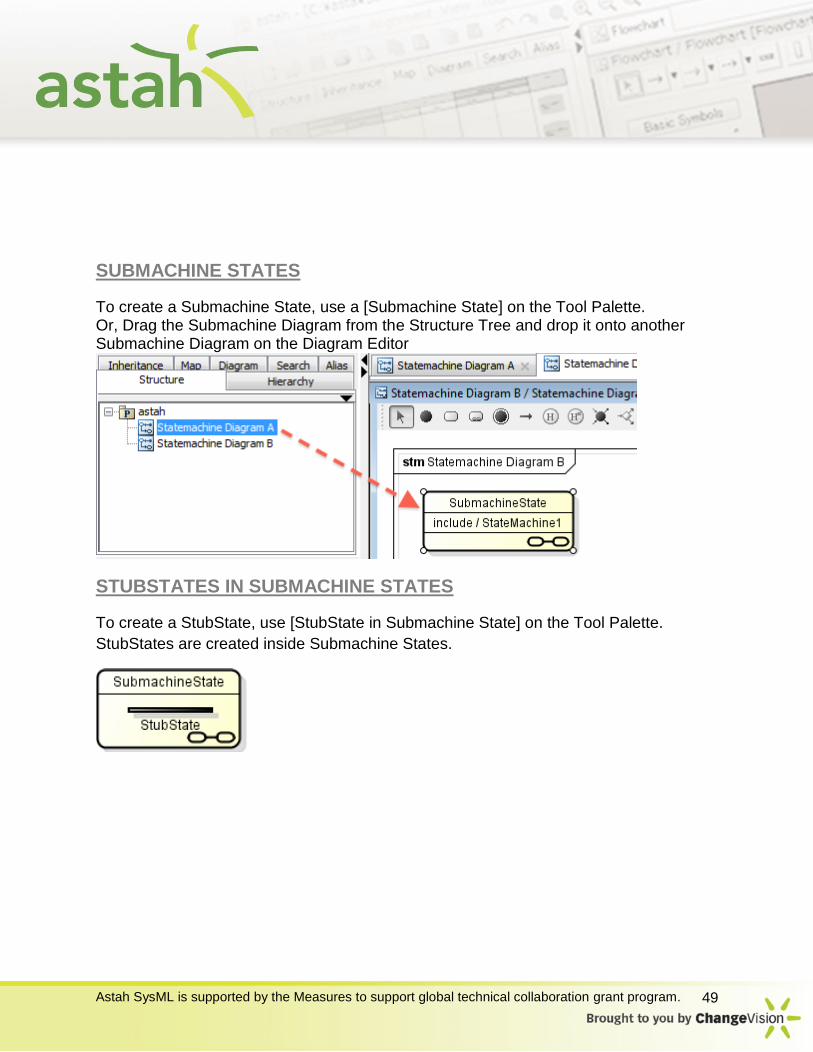
SUBMACHINE STATES
To create a Submachine State, use a [Submachine State] on the Tool Palette. Or, Drag the Submachine Diagram from the Structure Tree and drop it onto another Submachine Diagram on the Diagram Editor
STUBSTATES IN SUBMACHINE STATES
To create a StubState, use [StubState in Submachine State] on the Tool Palette.
StubStates are created inside Submachine States.
Astah SysML is supported by the Measures to support global technical collaboration grant program. 50
Activity Diagram
There are several ways to create an activity diagram. A) Using [Diagram] - [Activity Diagram] - [New Activity Diagram] or [Template Activity
Diagram] in the Main Menu. B) Using the [Structure Tree] in the “Project View” (by right-clicking).
Notes to use Template Activity Diagrams - A) A new Activity diagram will be created based on the selected Activity diagram by
[Template Activity Diagram] and it will lose both of the references of CallBehaviorActions and class information of the type of Object Node from the original Activity diagram.
B) To select a project file that contains more than one Activity Diagram, a new Activity diagram will be created based on the top Activity diagram in the project file.
When you create a diagram, it will be opened in the Diagram Editor.
Model elements on an Activity Diagram
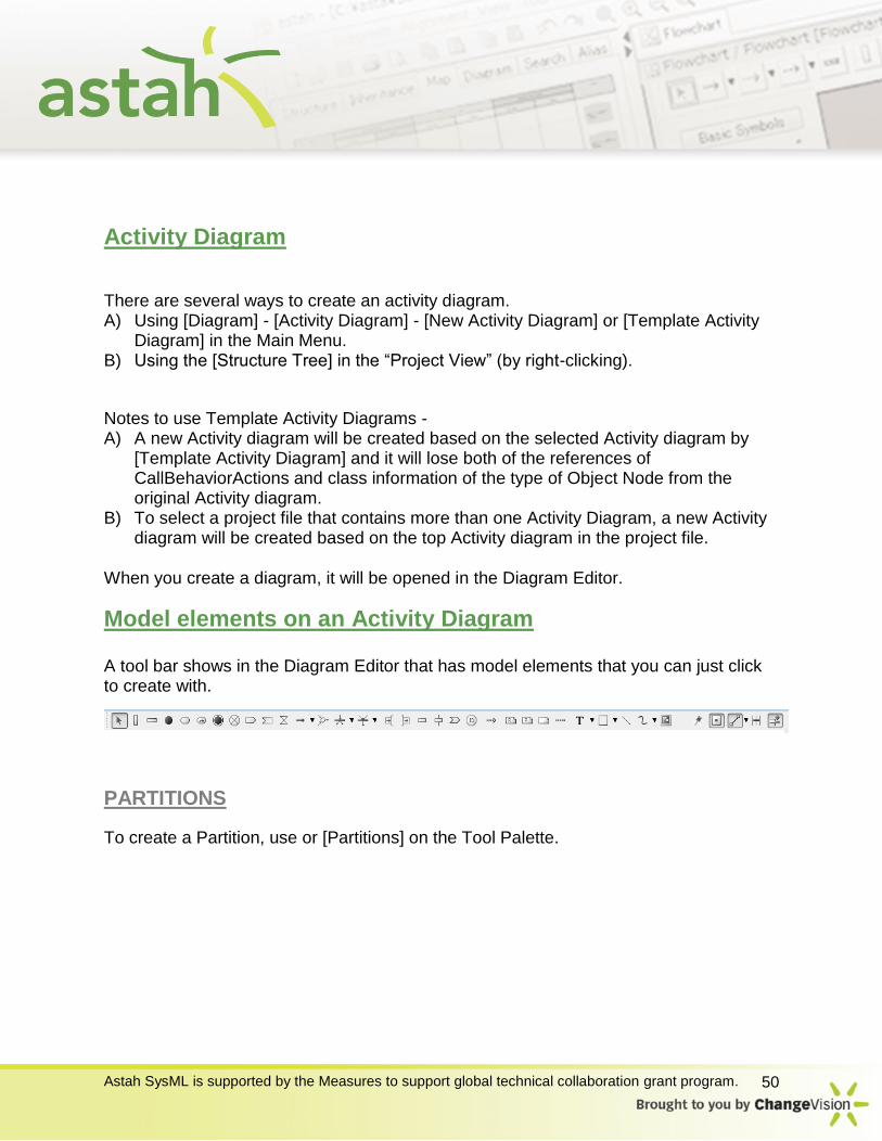
A tool bar shows in the Diagram Editor that has model elements that you can just click to create with.
PARTITIONS
To create a Partition, use or [Partitions] on the Tool Palette.

Astah SysML is supported by the Measures to support global technical collaboration grant program. 51
Double-click the Name of Partition in the Diagram Editor and then edit its name directly, or go to Base tab of the Partition in the Property View. Represent of the Partition can be added from Base tab of the Partition the Property View.
INITIAL NODES
To create an Initial Node, use [Initial Node] on the Tool Palette.

Astah SysML is supported by the Measures to support global technical collaboration grant program. 52
ACTION
To create an Action, use [Action] on the Tool Palette or double click on an Activity Diagram.
Double-click the name of Action in the diagram and then edit its name directly, or go to Entry tab of the Action in the Property View. To insert new lines in the Action name, press SHIFT+ENTER, ALT+ENTER, CTRL+ENTER.
CALLBEHAVIORACTION
To create a CallBehaviorAction, use a [Call Behavior Action] on the Tool Palette.
Or, Drag the Activity Diagram from the Structure Tree and drop it onto another Activity Diagram on the Diagram Editor (1) Select the Activity diagrams on the Structure Tree. (2) Drag the Activity diagrams and drop them onto another Activity Diagram Editor.
To edit CallBehaviorAction Names,Double-click the name of CallBehaviorAction in the diagram and edit its name directly, or go to Base tab of the CallBehaviorAction in the Property View.
ACTIVITY FINAL
To create an Activity Final, use [Activity Final] on the Tool Palette.

Astah SysML is supported by the Measures to support global technical collaboration grant program. 53
FLOW FINAL NODES
To create a Flow Final Node, use [Flow Final Node] on the Tool Palette.
SENDSIGNAL ACTIONS AND ACCEPTEVENT ACTIONS
To create a SendSignal Action, use [SendSignalAction] on the Tool Palette. To create an ActionEvent Action, use [AcceptEventAction] on the Tool Palette.
ACCEPTTIMEEVENTACTIONS
To create an AcceptTimeEventAction, use [AcceptTimeEventAction] on the Tool
Palette.
CONTROL FLOW/OBJECT FLOW
To create a Control Flow/Object Flow, use [Control Flow/Object Flow] on the Tool Palette or draw suggest feature of State/Object Node.
Actions can be set on Control Flows/Object Flows using Control Flows/Object Flows Properties.
MERGE NODES/DECISION NODES
To create a Merge Nodes & Decision Nodes, use [Merge Nodes & Decision Nodes] on the Tool Palette.

Astah SysML is supported by the Measures to support global technical collaboration grant program. 54
FORK NODES/JOIN NODES
To create a Fork Node, use [Fork Node] on the Tool Palette. To create a Join Node, use [Join Node] on the Tool Palette. They are also called "Synchronization Bars".
PARAMETER NODES
To create a parameter node, use [Parameter Node] on the Tool Palette and click the
frame which the parameter node should be added to.
INPUTPINS/OUTPUTPINS
To create an InputPin, use [InputPin] on the Tool Palette. To create an OutputPin, use [OutputPin] on the Tool Palette.
To add States, Right-click on the Pin and select [Add State], or go to Base tab of the Pin in the Property View.
OBJECT NODES

Astah SysML is supported by the Measures to support global technical collaboration grant program. 55
To create an Object Node, use [Object Node] on the Tool Palette.
To add States, Right-click on the Object Node and select [Add State], or go to Base tab of the Object Node in the Property View.
PROCESS
To create a Process, use [Process] on the Tool Palette.
CONNECTOR
To create a Connector, use [Connector] on the Tool Palette.
DEPENDENCIES
To create a Process, use [Dependency] on the Tool Palette.
Sequence Diagram
There are several ways to create a Sequence Diagram.
Astah SysML is supported by the Measures to support global technical collaboration grant program. 56
One is to go to [Diagram] – [Sequence Diagram] from Main menu, and another is to right-click a model (i.e. a package) in the Project view and then select [Create Diagram] – [Add Sequence Diagram].
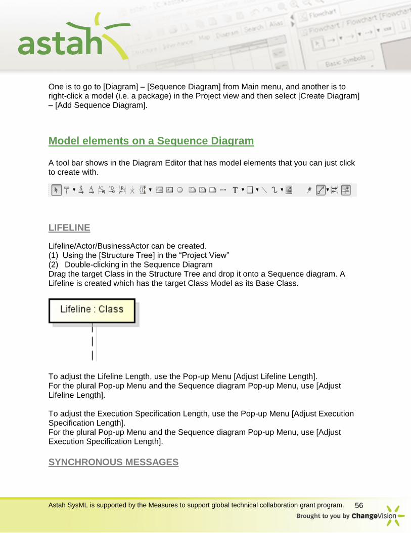
Model elements on a Sequence Diagram
A tool bar shows in the Diagram Editor that has model elements that you can just click to create with.
LIFELINE
Lifeline/Actor/BusinessActor can be created. (1) Using the [Structure Tree] in the “Project View” (2) Double-clicking in the Sequence Diagram Drag the target Class in the Structure Tree and drop it onto a Sequence diagram. A Lifeline is created which has the target Class Model as its Base Class.
To adjust the Lifeline Length, use the Pop-up Menu [Adjust Lifeline Length]. For the plural Pop-up Menu and the Sequence diagram Pop-up Menu, use [Adjust Lifeline Length]. To adjust the Execution Specification Length, use the Pop-up Menu [Adjust Execution Specification Length]. For the plural Pop-up Menu and the Sequence diagram Pop-up Menu, use [Adjust Execution Specification Length].
SYNCHRONOUS MESSAGES

Astah SysML is supported by the Measures to support global technical collaboration grant program. 57
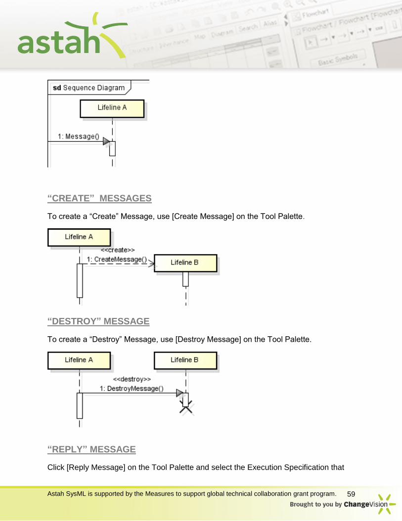
To create a Synchronous Message, use [Message] on the Tool Palette.
(1) Select [Message] from Tool palette (2) Click the Lifeline that sends the Message. (3) Click the Lifeline that receives the Message.
Using Suggest Feature: (1) Put mouse over a lifeline, execution specification, InteractionUse or Frame (2) Icon button appears, click on it (3) Click the lifeline you want to draw the arrow to
ASYNCHRONOUS MESSAGES
Asynchronuous message can be created in the same way as Synchronous Messages as described in Synchronous Messages section.
FOUND MESSAGES
To create a Found Message, use [Message] or [Asynchronous Message] on the Tool Palette. (1) Select [Message] or [Asynchronous Message] on the Tool Palette (2) Click on where this message origins in the diagram except on the lifeline (3) Click the Lifeline that receives the Message

Astah SysML is supported by the Measures to support global technical collaboration grant program. 58
LOST MESSAGES
To create a Lost Message, use [Message] or [Asynchronous Message] on the Tool Palette.
(1) Select [Message] or [Asynchronous Message] on the Tool Palette (2) Click the lifeline where the message origins (3) Click on the where the message ends in the diagram except on the Lifeline
GATE
To create a Gate, use [Message] or [Asynchronous Message] on the Tool Palette. (1) Select [Message] or [Asynchronous Message] on the tool Palette (2) Click the Frame where the message origins (3) Click the Lifeline that receives the Message
Astah SysML is supported by the Measures to support global technical collaboration grant program. 59
“CREATE” MESSAGES
To create a “Create” Message, use [Create Message] on the Tool Palette.
“DESTROY” MESSAGE
To create a “Destroy” Message, use [Destroy Message] on the Tool Palette.
“REPLY” MESSAGE
Click [Reply Message] on the Tool Palette and select the Execution Specification that

Astah SysML is supported by the Measures to support global technical collaboration grant program. 60
sends the “Reply” Message.
Or, use [Reply Message Automatic Mode] on the Tool Bar or select [Create Reply Message] from Message’s Pop-up menu.
STOP
To create a Stop, use [Stop] on the Tool Palette. (1) Select [Stop] on the Tool Palette (2) Click the target Lifeline
DURATION CONSTRAINT AND TIME CONSTRAINT
To create a Duration Constraint, use [Duration Constraint] on the Tool Palette. (1) Select [Duration Constraint] on the Tool Palette (2) Click on lifelines
To create a Time Constraint, use [Time Constraint] on the Tool Palette. (1) Select [Time Constraint] on the Tool Palette (2) Click a lifeline
Astah SysML is supported by the Measures to support global technical collaboration grant program. 61
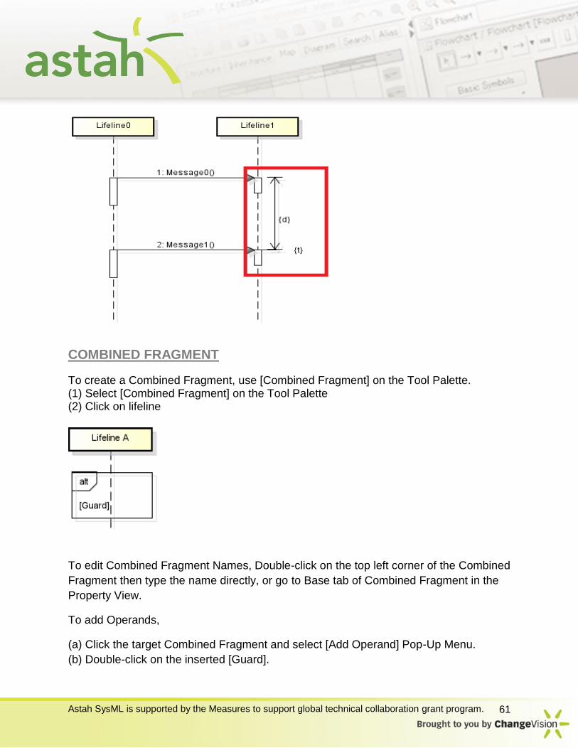
COMBINED FRAGMENT
To create a Combined Fragment, use [Combined Fragment] on the Tool Palette. (1) Select [Combined Fragment] on the Tool Palette (2) Click on lifeline
To edit Combined Fragment Names, Double-click on the top left corner of the Combined
Fragment then type the name directly, or go to Base tab of Combined Fragment in the
Property View.
To add Operands,
(a) Click the target Combined Fragment and select [Add Operand] Pop-Up Menu.
(b) Double-click on the inserted [Guard].
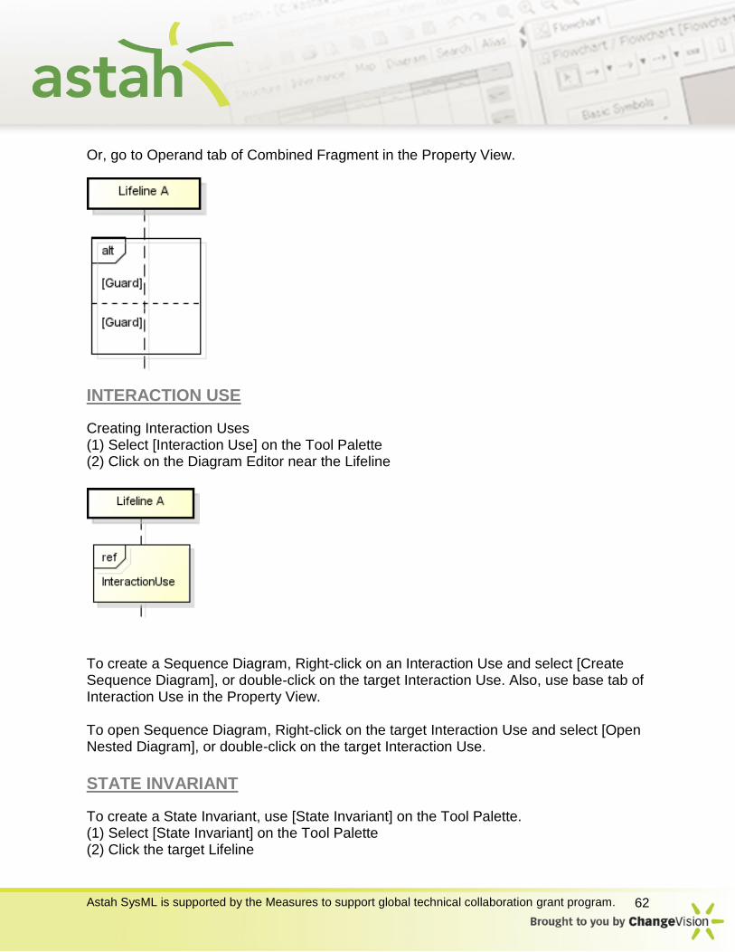
Astah SysML is supported by the Measures to support global technical collaboration grant program. 62
Or, go to Operand tab of Combined Fragment in the Property View.
INTERACTION USE
Creating Interaction Uses (1) Select [Interaction Use] on the Tool Palette (2) Click on the Diagram Editor near the Lifeline
To create a Sequence Diagram, Right-click on an Interaction Use and select [Create Sequence Diagram], or double-click on the target Interaction Use. Also, use base tab of Interaction Use in the Property View. To open Sequence Diagram, Right-click on the target Interaction Use and select [Open Nested Diagram], or double-click on the target Interaction Use.
STATE INVARIANT
To create a State Invariant, use [State Invariant] on the Tool Palette. (1) Select [State Invariant] on the Tool Palette (2) Click the target Lifeline
Astah SysML is supported by the Measures to support global technical collaboration grant program. 63
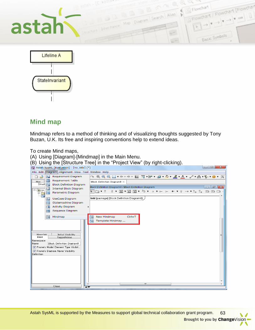
Mind map
Mindmap refers to a method of thinking and of visualizing thoughts suggested by Tony Buzan, U.K. Its free and inspiring conventions help to extend ideas. To create Mind maps, (A) Using [Diagram]-[Mindmap] in the Main Menu. (B) Using the [Structure Tree] in the “Project View” (by right-clicking).
Astah SysML is supported by the Measures to support global technical collaboration grant program. 64
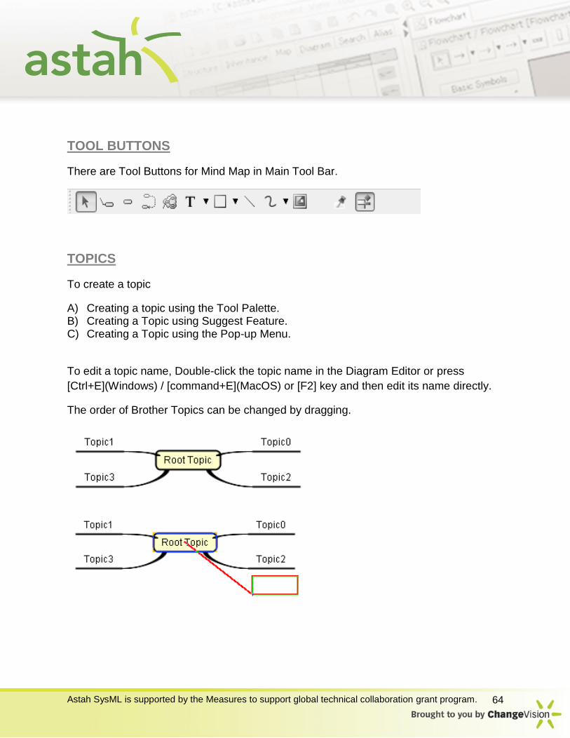
TOOL BUTTONS
There are Tool Buttons for Mind Map in Main Tool Bar.
TOPICS
To create a topic
A) Creating a topic using the Tool Palette. B) Creating a Topic using Suggest Feature. C) Creating a Topic using the Pop-up Menu.
To edit a topic name, Double-click the topic name in the Diagram Editor or press
[Ctrl+E](Windows) / [command+E](MacOS) or [F2] key and then edit its name directly.
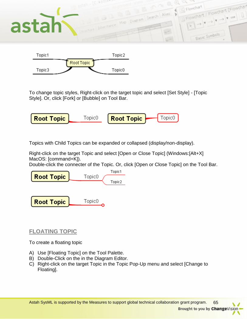
The order of Brother Topics can be changed by dragging.
Astah SysML is supported by the Measures to support global technical collaboration grant program. 65
To change topic styles, Right-click on the target topic and select [Set Style] - [Topic Style]. Or, click [Fork] or [Bubble] on Tool Bar.
Topics with Child Topics can be expanded or collapsed (display/non-display).
Right-click on the target Topic and select [Open or Close Topic] (Windows:[Alt+X] MacOS: [command+K]). Double-click the connecter of the Topic. Or, click [Open or Close Topic] on the Tool Bar.
FLOATING TOPIC
To create a floating topic
A) Use [Floating Topic] on the Tool Palette. B) Double-Click on the in the Diagram Editor. C) Right-click on the target Topic in the Topic Pop-Up menu and select [Change to
Floating].
Astah SysML is supported by the Measures to support global technical collaboration grant program. 66
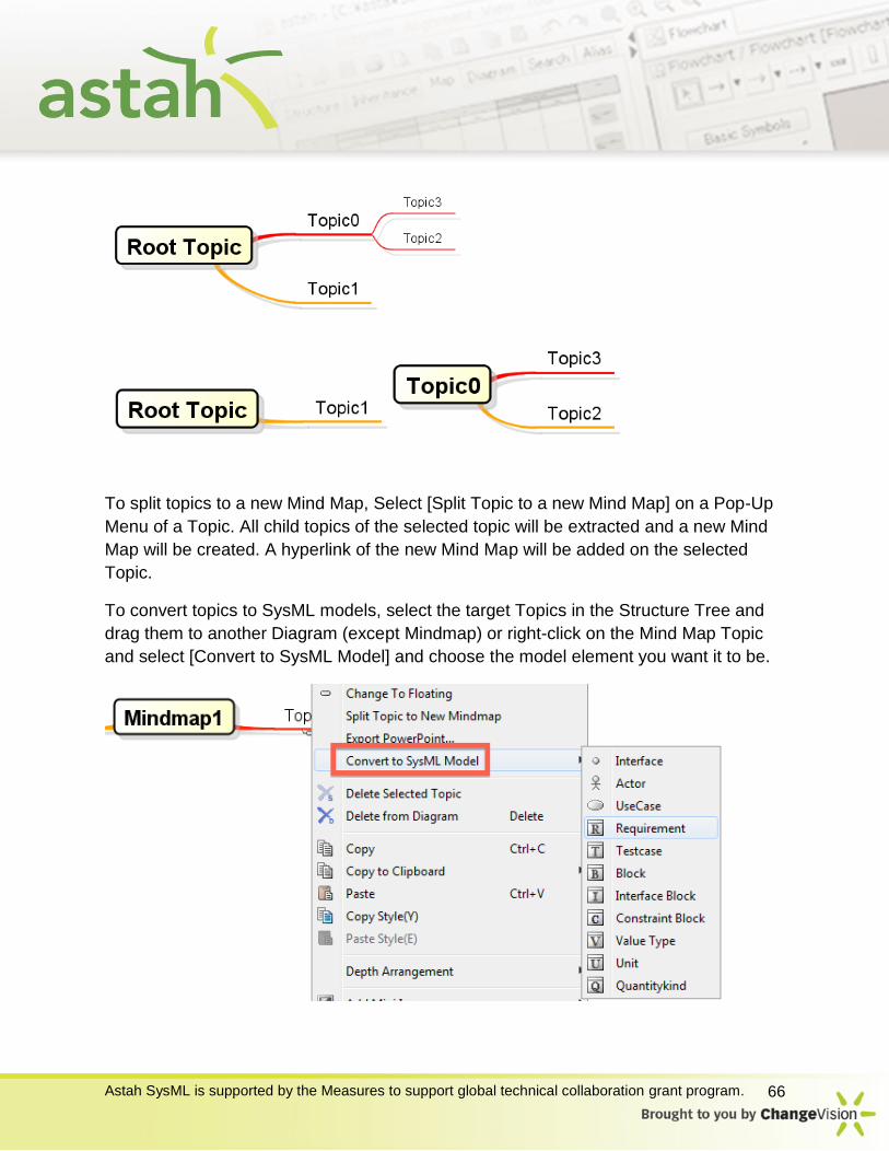
To split topics to a new Mind Map, Select [Split Topic to a new Mind Map] on a Pop-Up
Menu of a Topic. All child topics of the selected topic will be extracted and a new Mind
Map will be created. A hyperlink of the new Mind Map will be added on the selected
Topic.
To convert topics to SysML models, select the target Topics in the Structure Tree and
drag them to another Diagram (except Mindmap) or right-click on the Mind Map Topic
and select [Convert to SysML Model] and choose the model element you want it to be.
Astah SysML is supported by the Measures to support global technical collaboration grant program. 67
EDGES
Edges are automatically created when Child Topics are created. Edges cannot be
created by themselves. To change styles/Line Width, Right-click on the target Edge and
select [Edge Style]/[Line Width].
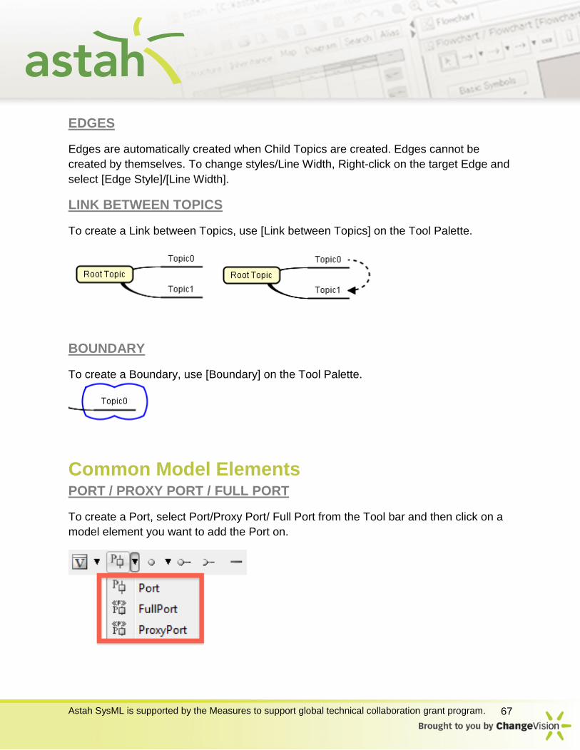
LINK BETWEEN TOPICS
To create a Link between Topics, use [Link between Topics] on the Tool Palette.
BOUNDARY
To create a Boundary, use [Boundary] on the Tool Palette.
Common Model Elements PORT / PROXY PORT / FULL PORT
To create a Port, select Port/Proxy Port/ Full Port from the Tool bar and then click on a
model element you want to add the Port on.
Astah SysML is supported by the Measures to support global technical collaboration grant program. 68
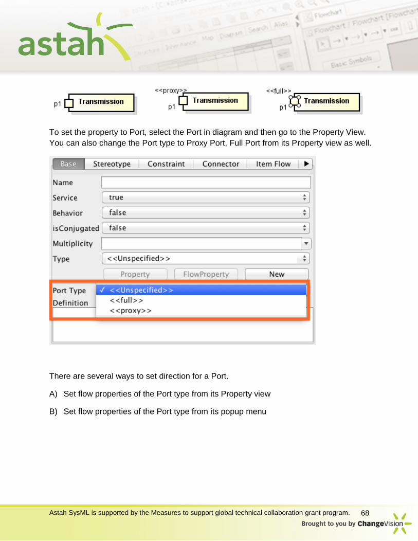
To set the property to Port, select the Port in diagram and then go to the Property View.
You can also change the Port type to Proxy Port, Full Port from its Property view as well.
There are several ways to set direction for a Port.
A) Set flow properties of the Port type from its Property view
B) Set flow properties of the Port type from its popup menu

Astah SysML is supported by the Measures to support global technical collaboration grant program. 69
INTERFACE
To create an Interface, select [Interface] from tool bar and click in the diagram. You can
choose which notation you’d like to use from this tool bar directly. But you can always
change its notation from [Icon Notation] option from its Pop-up menu.
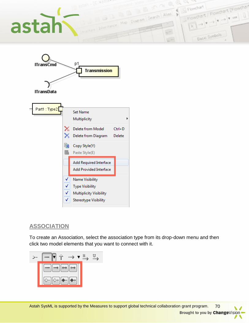
PROVIDED INTERFACE/REQUIRED INTERFACE
To create a Provided/Required Interface, select it from the tool bar and then click in the
diagram.
You can also create them directly from Port’s Pop-up menu.
Astah SysML is supported by the Measures to support global technical collaboration grant program. 70
ASSOCIATION
To create an Association, select the association type from its drop-down menu and then
click two model elements that you want to connect with it.
Astah SysML is supported by the Measures to support global technical collaboration grant program. 71
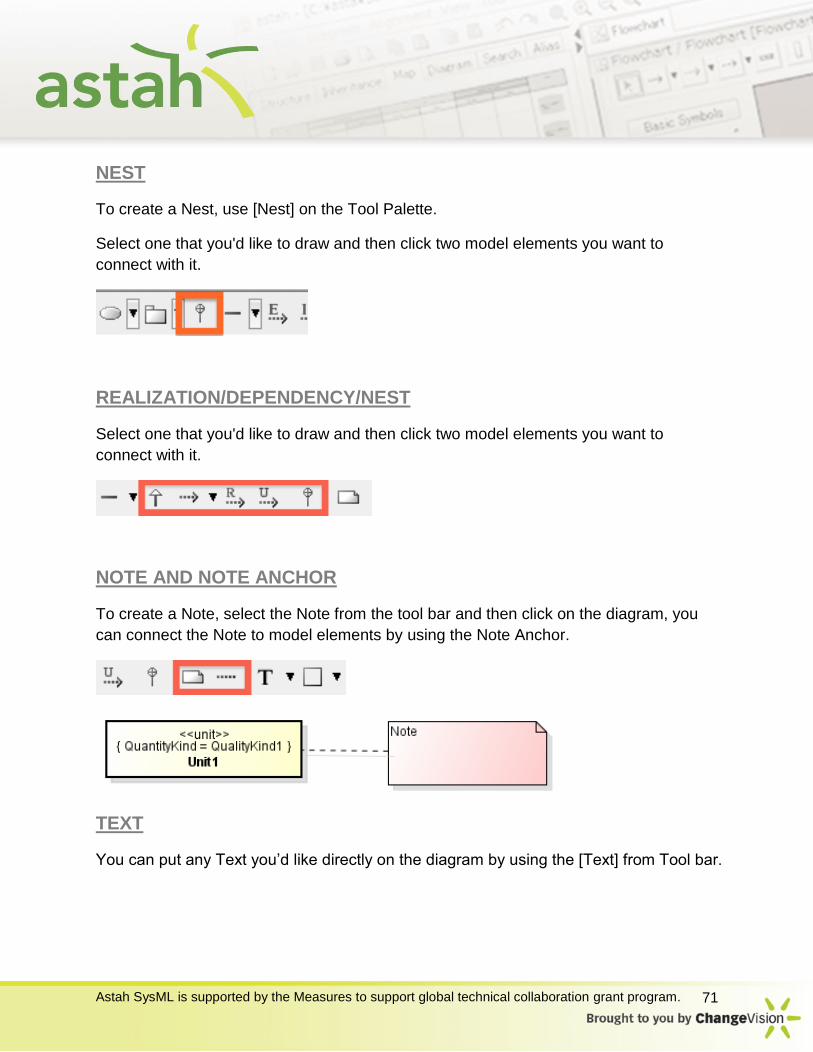
NEST
To create a Nest, use [Nest] on the Tool Palette.
Select one that you'd like to draw and then click two model elements you want to
connect with it.
REALIZATION/DEPENDENCY/NEST
Select one that you'd like to draw and then click two model elements you want to
connect with it.
NOTE AND NOTE ANCHOR
To create a Note, select the Note from the tool bar and then click on the diagram, you
can connect the Note to model elements by using the Note Anchor.
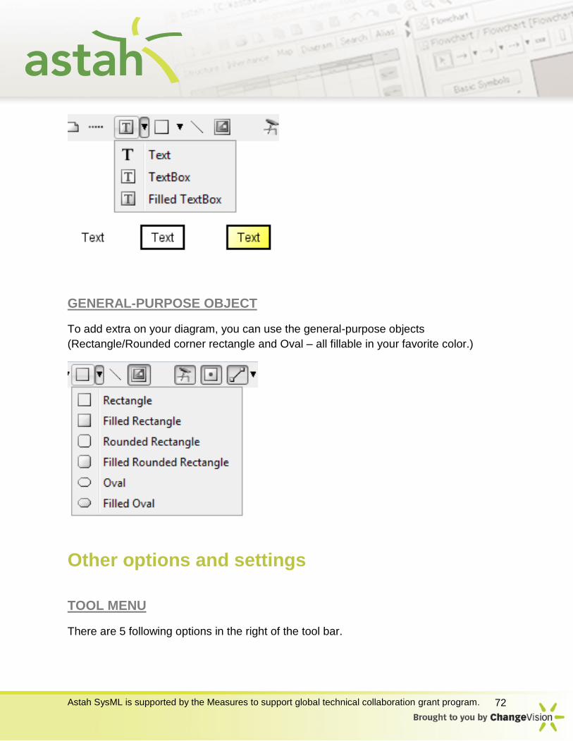
TEXT
You can put any Text you’d like directly on the diagram by using the [Text] from Tool bar.
Astah SysML is supported by the Measures to support global technical collaboration grant program. 72
GENERAL-PURPOSE OBJECT
To add extra on your diagram, you can use the general-purpose objects
(Rectangle/Rounded corner rectangle and Oval – all fillable in your favorite color.)
Other options and settings
TOOL MENU
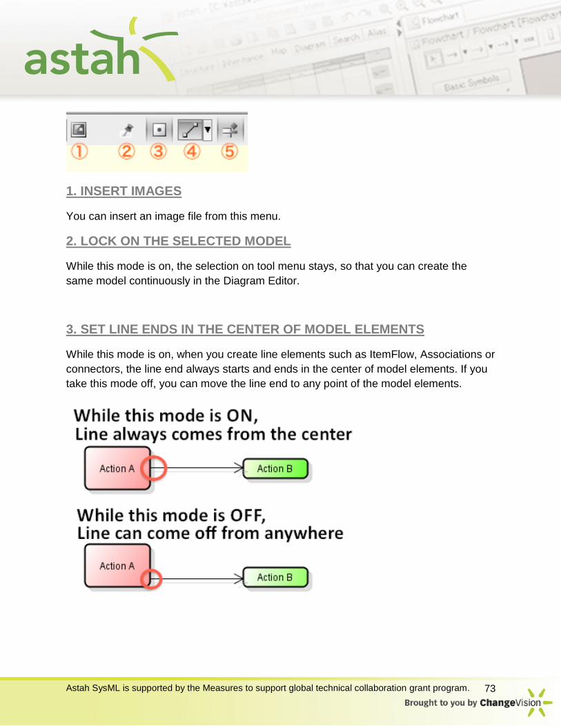
There are 5 following options in the right of the tool bar.
Astah SysML is supported by the Measures to support global technical collaboration grant program. 73
1. INSERT IMAGES
You can insert an image file from this menu.
2. LOCK ON THE SELECTED MODEL
While this mode is on, the selection on tool menu stays, so that you can create the
same model continuously in the Diagram Editor.
3. SET LINE ENDS IN THE CENTER OF MODEL ELEMENTS
While this mode is on, when you create line elements such as ItemFlow, Associations or
connectors, the line end always starts and ends in the center of model elements. If you
take this mode off, you can move the line end to any point of the model elements.
Astah SysML is supported by the Measures to support global technical collaboration grant program. 74
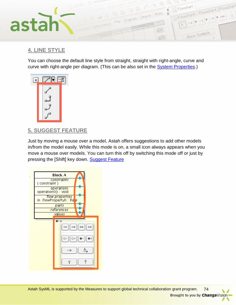
4. LINE STYLE
You can choose the default line style from straight, straight with right-angle, curve and
curve with right-angle per diagram. (This can be also set in the System Properties.)
5. SUGGEST FEATURE
Just by moving a mouse over a model, Astah offers suggestions to add other models
in/from the model easily. While this mode is on, a small icon always appears when you
move a mouse over models. You can turn this off by switching this mode off or just by
pressing the [Shift] key down. Suggest Feature
Astah SysML is supported by the Measures to support global technical collaboration grant program. 75
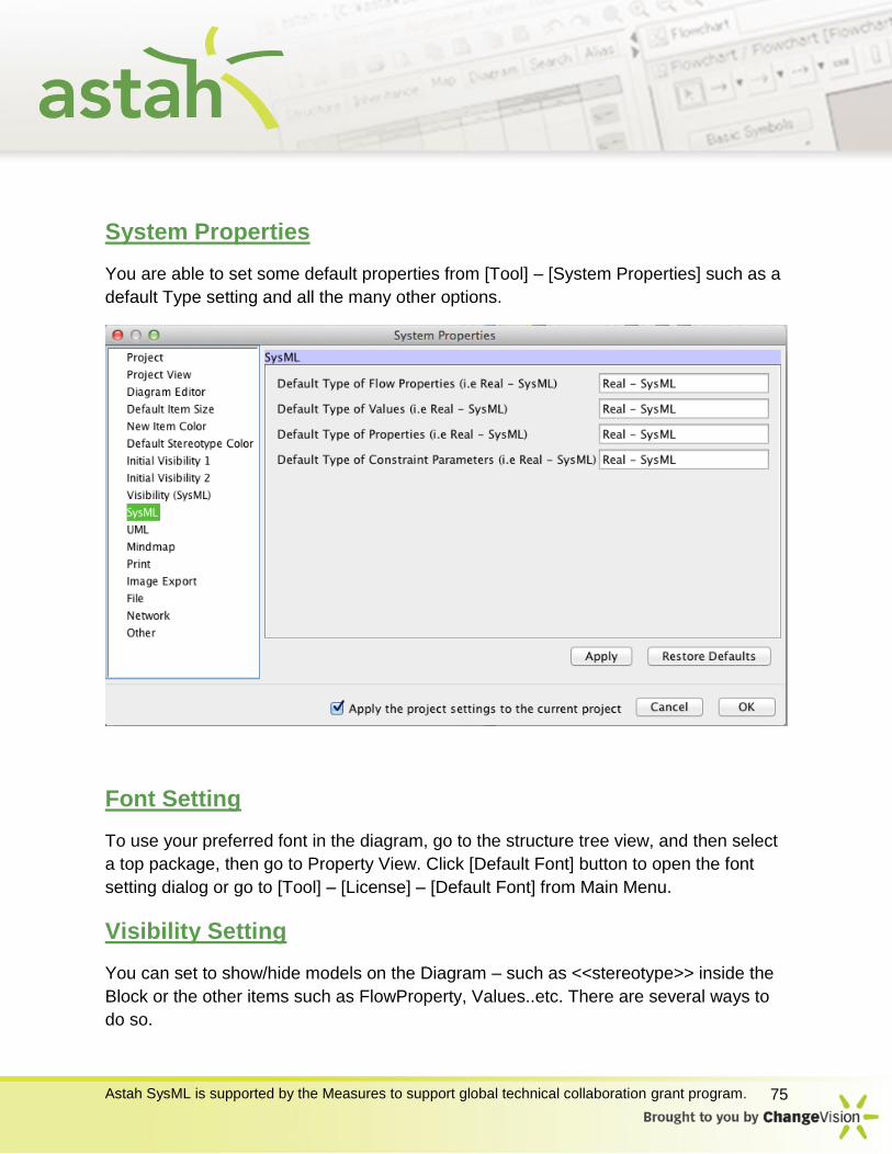
System Properties
You are able to set some default properties from [Tool] – [System Properties] such as a
default Type setting and all the many other options.
Font Setting
To use your preferred font in the diagram, go to the structure tree view, and then select
a top package, then go to Property View. Click [Default Font] button to open the font
setting dialog or go to [Tool] – [License] – [Default Font] from Main Menu.
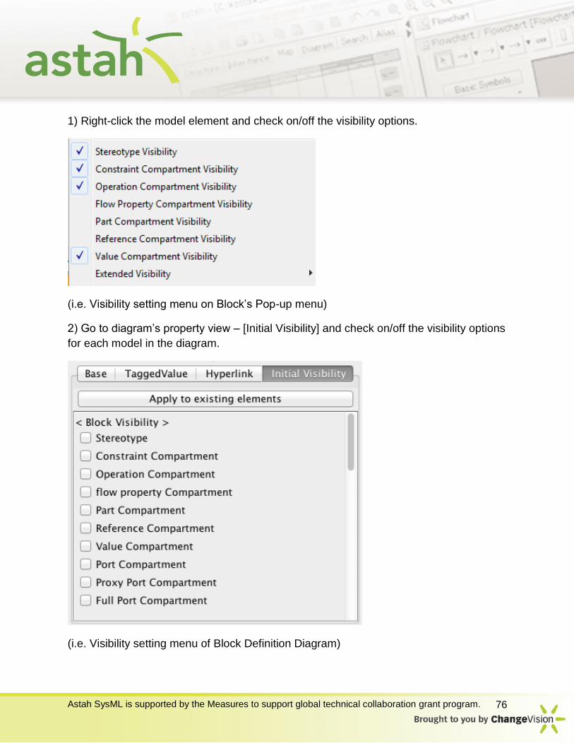
Visibility Setting
You can set to show/hide models on the Diagram – such as <<stereotype>> inside the
Block or the other items such as FlowProperty, Values..etc. There are several ways to
do so.
Astah SysML is supported by the Measures to support global technical collaboration grant program. 76
1) Right-click the model element and check on/off the visibility options.
(i.e. Visibility setting menu on Block’s Pop-up menu)
2) Go to diagram’s property view – [Initial Visibility] and check on/off the visibility options
for each model in the diagram.
(i.e. Visibility setting menu of Block Definition Diagram)
Astah SysML is supported by the Measures to support global technical collaboration grant program. 77
You can also set all the default visibility settings from [Tool] – [System Properties] –
[Initial Visibility 1,2 and SysML].
Copy and Paste .asml files
In Astah SysML you can easily copy and paste models from diagrams in one .asml file
to another.
1. Select model you want to copy and go [Edit] - [Copy] or use shortcut key for copying
(Ctrl + C)
2. Open a blank diagram where you want to paste the copied models. And then go to
[Edit] - [Paste] or use the shortcut key for pasting - Ctrl + V.
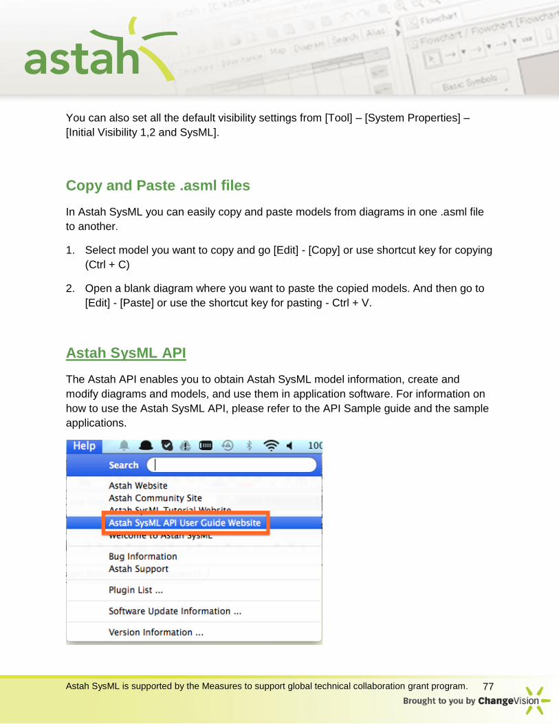
Astah SysML API
The Astah API enables you to obtain Astah SysML model information, create and
modify diagrams and models, and use them in application software. For information on
how to use the Astah SysML API, please refer to the API Sample guide and the sample
applications.
Astah SysML is supported by the Measures to support global technical collaboration grant program. 78
Send us Feedback
We’ll keep update our manual and also online contents.
If you have any feedback or feature requests, please send us them to [email protected].
Thank you!
Astah Development Team


![Astah SysML QuickStartGuide(Ja)...astah* SysML is supported by the Measures to support global technical collaboration grant program. 12 ªp ¯ Ê [v astah*uR[e ew [ªp ¯ x± Ê ]cp](https://static.fdocuments.us/doc/165x107/5e991d909a83433e8b311b32/astah-sysml-quickstartguideja-astah-sysml-is-supported-by-the-measures-to.jpg)