AssuredSAN 4004 Series FRU Installation and Replacement Guide - Seagate… · 2017-03-27 ·...
98
AssuredSAN 4004 Series FRU Installation and Replacement Guide For firmware release G222 P/N 83-00006700-13-01 Revision A January 2016 Abstract This document describes removal and installation of field-replaceable units for Dot Hill AssuredSAN 4004 Series controller enclosures, and is intended for use by storage system administrators familiar with servers and computer networks, network administration, storage system installation and configuration, storage area network management, and relevant protocols.
Transcript of AssuredSAN 4004 Series FRU Installation and Replacement Guide - Seagate… · 2017-03-27 ·...

AssuredSAN 4004 SeriesFRU Installation and Replacement GuideFor firmware release G222
P/N 83-00006700-13-01Revision AJanuary 2016
Abstract
This document describes removal and installation of field-replaceable units for Dot Hill AssuredSAN 4004 Series controller enclosures, and is intended for use by storage system administrators familiar with servers and computer networks, network administration, storage system installation and configuration, storage area network management, and relevant protocols.

Copyright © 2016 Dot Hill Systems Corp. All rights reserved. Dot Hill Systems Corp., Dot Hill, the Dot Hill logo, AssuredSAN, AssuredSnap, AssuredCopy, AssuredRemote, R/Evolution, and the R/Evolution logo are trademarks of Dot Hill Systems Corp. All other trademarks and registered trademarks are proprietary to their respective owners.
The material in this document is for information only and is subject to change without notice. While reasonable efforts have been made in the preparation of this document to assure its accuracy, changes in the product design can be made without reservation and without notification to its users.

AssuredSAN 4004 Series FRU Installation and Replacement Guide 3
About this guide. . . . . . . . . . . . . . . . . . . . . . . . . . . . . . . . . . . . . . . . . . . . . . . . . . . . . . . 9Overview. . . . . . . . . . . . . . . . . . . . . . . . . . . . . . . . . . . . . . . . . . . . . . . . . . . . . . . . . . . . . . . . . . . . . . 9
AssuredSAN 4004 Series enclosure user interfaces . . . . . . . . . . . . . . . . . . . . . . . . . . . . . . . . . . . . . . 9Intended audience . . . . . . . . . . . . . . . . . . . . . . . . . . . . . . . . . . . . . . . . . . . . . . . . . . . . . . . . . . . . . . 10Prerequisites. . . . . . . . . . . . . . . . . . . . . . . . . . . . . . . . . . . . . . . . . . . . . . . . . . . . . . . . . . . . . . . . . . . 10Related documentation . . . . . . . . . . . . . . . . . . . . . . . . . . . . . . . . . . . . . . . . . . . . . . . . . . . . . . . . . . . 10Document conventions and symbols . . . . . . . . . . . . . . . . . . . . . . . . . . . . . . . . . . . . . . . . . . . . . . . . . . 11
1 FRUs . . . . . . . . . . . . . . . . . . . . . . . . . . . . . . . . . . . . . . . . . . . . . . . . . . . . . . . . . . . . 12Available FRUs. . . . . . . . . . . . . . . . . . . . . . . . . . . . . . . . . . . . . . . . . . . . . . . . . . . . . . . . . . . . . . . . . 12
Storage enclosure overview . . . . . . . . . . . . . . . . . . . . . . . . . . . . . . . . . . . . . . . . . . . . . . . . . . . . . 12FRUs addressing 48-drive enclosures . . . . . . . . . . . . . . . . . . . . . . . . . . . . . . . . . . . . . . . . . . . . . . . 13
Enclosure bezel for 48-drive model . . . . . . . . . . . . . . . . . . . . . . . . . . . . . . . . . . . . . . . . . . . . . . 16FRUs addressing 24-drive enclosures . . . . . . . . . . . . . . . . . . . . . . . . . . . . . . . . . . . . . . . . . . . . . . . 18
Enclosure bezel for 24-drive model . . . . . . . . . . . . . . . . . . . . . . . . . . . . . . . . . . . . . . . . . . . . . . 20FRUs addressing 56-drive enclosures . . . . . . . . . . . . . . . . . . . . . . . . . . . . . . . . . . . . . . . . . . . . . . . 22
Enclosure bezel for 56-drive model . . . . . . . . . . . . . . . . . . . . . . . . . . . . . . . . . . . . . . . . . . . . . . 25FRUs addressing 12-drive enclosures . . . . . . . . . . . . . . . . . . . . . . . . . . . . . . . . . . . . . . . . . . . . . . . 26
Enclosure bezel for 12-drive model . . . . . . . . . . . . . . . . . . . . . . . . . . . . . . . . . . . . . . . . . . . . . . 28Supported drive enclosures . . . . . . . . . . . . . . . . . . . . . . . . . . . . . . . . . . . . . . . . . . . . . . . . . . . . . . 29
2 Procedures . . . . . . . . . . . . . . . . . . . . . . . . . . . . . . . . . . . . . . . . . . . . . . . . . . . . . . . 30Electrostatic discharge. . . . . . . . . . . . . . . . . . . . . . . . . . . . . . . . . . . . . . . . . . . . . . . . . . . . . . . . . . . . 30
Preventing electrostatic discharge . . . . . . . . . . . . . . . . . . . . . . . . . . . . . . . . . . . . . . . . . . . . . . . . . 30Grounding methods to prevent electrostatic discharge . . . . . . . . . . . . . . . . . . . . . . . . . . . . . . . . . . . 30
Replacing chassis FRU components . . . . . . . . . . . . . . . . . . . . . . . . . . . . . . . . . . . . . . . . . . . . . . . . . . . 31Attaching and removing the enclosure bezel . . . . . . . . . . . . . . . . . . . . . . . . . . . . . . . . . . . . . . . . . . . . 32
Attaching the enclosure bezel (2U). . . . . . . . . . . . . . . . . . . . . . . . . . . . . . . . . . . . . . . . . . . . . . . . . 33Removing the enclosure bezel (2U) . . . . . . . . . . . . . . . . . . . . . . . . . . . . . . . . . . . . . . . . . . . . . . . . 33Attaching the enclosure bezel (4U). . . . . . . . . . . . . . . . . . . . . . . . . . . . . . . . . . . . . . . . . . . . . . . . . 33Removing the enclosure bezel (4U) . . . . . . . . . . . . . . . . . . . . . . . . . . . . . . . . . . . . . . . . . . . . . . . . 33
Replacing a controller module or expansion module . . . . . . . . . . . . . . . . . . . . . . . . . . . . . . . . . . . . . . . 34Before you begin . . . . . . . . . . . . . . . . . . . . . . . . . . . . . . . . . . . . . . . . . . . . . . . . . . . . . . . . . . . . . 34Configuring partner firmware update . . . . . . . . . . . . . . . . . . . . . . . . . . . . . . . . . . . . . . . . . . . . . . . 35
Using the SMC or RAIDar . . . . . . . . . . . . . . . . . . . . . . . . . . . . . . . . . . . . . . . . . . . . . . . . . . . . 35Using the CLI . . . . . . . . . . . . . . . . . . . . . . . . . . . . . . . . . . . . . . . . . . . . . . . . . . . . . . . . . . . . . 35
Verifying component failure . . . . . . . . . . . . . . . . . . . . . . . . . . . . . . . . . . . . . . . . . . . . . . . . . . . . . 36Stopping I/O . . . . . . . . . . . . . . . . . . . . . . . . . . . . . . . . . . . . . . . . . . . . . . . . . . . . . . . . . . . . . . . 36Shutting down a controller module . . . . . . . . . . . . . . . . . . . . . . . . . . . . . . . . . . . . . . . . . . . . . . . . . 37
Using the SMC or RAIDar . . . . . . . . . . . . . . . . . . . . . . . . . . . . . . . . . . . . . . . . . . . . . . . . . . . . 37Using the CLI . . . . . . . . . . . . . . . . . . . . . . . . . . . . . . . . . . . . . . . . . . . . . . . . . . . . . . . . . . . . . 38
Removing a controller module or expansion module. . . . . . . . . . . . . . . . . . . . . . . . . . . . . . . . . . . . . 38Transporting CompactFlash. . . . . . . . . . . . . . . . . . . . . . . . . . . . . . . . . . . . . . . . . . . . . . . . . . . . . . 40Installing a controller module or expansion module . . . . . . . . . . . . . . . . . . . . . . . . . . . . . . . . . . . . . 41Verifying component operation . . . . . . . . . . . . . . . . . . . . . . . . . . . . . . . . . . . . . . . . . . . . . . . . . . . 42
Using the SMC or RAIDar . . . . . . . . . . . . . . . . . . . . . . . . . . . . . . . . . . . . . . . . . . . . . . . . . . . . 42Using the CLI . . . . . . . . . . . . . . . . . . . . . . . . . . . . . . . . . . . . . . . . . . . . . . . . . . . . . . . . . . . . . 43
Updating firmware . . . . . . . . . . . . . . . . . . . . . . . . . . . . . . . . . . . . . . . . . . . . . . . . . . . . . . . . . . . . . . 43Accessing drawers . . . . . . . . . . . . . . . . . . . . . . . . . . . . . . . . . . . . . . . . . . . . . . . . . . . . . . . . . . . . . . 44
Accessing a 2U16 drawer . . . . . . . . . . . . . . . . . . . . . . . . . . . . . . . . . . . . . . . . . . . . . . . . . . . . . . 44Opening and closing a 2U16 drawer . . . . . . . . . . . . . . . . . . . . . . . . . . . . . . . . . . . . . . . . . . . . 44Aligning an AMS or disk module for installation into a 2U16 drawer . . . . . . . . . . . . . . . . . . . . . . 45
Accessing a 4U28 drawer . . . . . . . . . . . . . . . . . . . . . . . . . . . . . . . . . . . . . . . . . . . . . . . . . . . . . . 46Opening and closing a 4U28 drawer . . . . . . . . . . . . . . . . . . . . . . . . . . . . . . . . . . . . . . . . . . . . 46
Contents

4 Contents
Replacing a disk drive module . . . . . . . . . . . . . . . . . . . . . . . . . . . . . . . . . . . . . . . . . . . . . . . . . . . . . . 48FDE considerations . . . . . . . . . . . . . . . . . . . . . . . . . . . . . . . . . . . . . . . . . . . . . . . . . . . . . . . . . . . 48Air management in disk drive slots. . . . . . . . . . . . . . . . . . . . . . . . . . . . . . . . . . . . . . . . . . . . . . . . . 49
Air management modules . . . . . . . . . . . . . . . . . . . . . . . . . . . . . . . . . . . . . . . . . . . . . . . . . . . . 49Air management solution insert. . . . . . . . . . . . . . . . . . . . . . . . . . . . . . . . . . . . . . . . . . . . . . . . . 49
Before you begin . . . . . . . . . . . . . . . . . . . . . . . . . . . . . . . . . . . . . . . . . . . . . . . . . . . . . . . . . . . . . 51Verifying component failure . . . . . . . . . . . . . . . . . . . . . . . . . . . . . . . . . . . . . . . . . . . . . . . . . . . . . 51Removing a disk drive module (2U12/2U24) . . . . . . . . . . . . . . . . . . . . . . . . . . . . . . . . . . . . . . . . . 52Removing a disk drive module (2U48) . . . . . . . . . . . . . . . . . . . . . . . . . . . . . . . . . . . . . . . . . . . . . . 53Removing a disk drive module (4U56) . . . . . . . . . . . . . . . . . . . . . . . . . . . . . . . . . . . . . . . . . . . . . . 54Installing a disk drive module (2U12/2U24). . . . . . . . . . . . . . . . . . . . . . . . . . . . . . . . . . . . . . . . . . 55Installing a disk drive module (2U48) . . . . . . . . . . . . . . . . . . . . . . . . . . . . . . . . . . . . . . . . . . . . . . . 56Installing a disk drive module (4U56) . . . . . . . . . . . . . . . . . . . . . . . . . . . . . . . . . . . . . . . . . . . . . . . 57Completing the disk module installation . . . . . . . . . . . . . . . . . . . . . . . . . . . . . . . . . . . . . . . . . . . . . 58Determine if a disk is missing . . . . . . . . . . . . . . . . . . . . . . . . . . . . . . . . . . . . . . . . . . . . . . . . . . . . 59
Using the SMC or RAIDar . . . . . . . . . . . . . . . . . . . . . . . . . . . . . . . . . . . . . . . . . . . . . . . . . . . . 59Using the CLI . . . . . . . . . . . . . . . . . . . . . . . . . . . . . . . . . . . . . . . . . . . . . . . . . . . . . . . . . . . . . 59
Verifying component operation . . . . . . . . . . . . . . . . . . . . . . . . . . . . . . . . . . . . . . . . . . . . . . . . . . . 60Replacing a power supply module . . . . . . . . . . . . . . . . . . . . . . . . . . . . . . . . . . . . . . . . . . . . . . . . . . . 60
Before you begin . . . . . . . . . . . . . . . . . . . . . . . . . . . . . . . . . . . . . . . . . . . . . . . . . . . . . . . . . . . . . 60Verifying component failure . . . . . . . . . . . . . . . . . . . . . . . . . . . . . . . . . . . . . . . . . . . . . . . . . . . . . 60Power supply units . . . . . . . . . . . . . . . . . . . . . . . . . . . . . . . . . . . . . . . . . . . . . . . . . . . . . . . . . . . . 61
AC PSU (2U12 and 2U24) . . . . . . . . . . . . . . . . . . . . . . . . . . . . . . . . . . . . . . . . . . . . . . . . . . . 62DC and AC PSUs with power switch (2U) . . . . . . . . . . . . . . . . . . . . . . . . . . . . . . . . . . . . . . . . . 63AC PSUs with power switch (2U48) . . . . . . . . . . . . . . . . . . . . . . . . . . . . . . . . . . . . . . . . . . . . . 64AC and DC PSUs with power switch (4U56) . . . . . . . . . . . . . . . . . . . . . . . . . . . . . . . . . . . . . . . 64
Removing a power supply unit (2U models) . . . . . . . . . . . . . . . . . . . . . . . . . . . . . . . . . . . . . . . . . . 65Removing a power supply unit (4U models) . . . . . . . . . . . . . . . . . . . . . . . . . . . . . . . . . . . . . . . . . . 66Installing a power supply unit (2U models) . . . . . . . . . . . . . . . . . . . . . . . . . . . . . . . . . . . . . . . . . . . 67Connecting a power cable (2U models) . . . . . . . . . . . . . . . . . . . . . . . . . . . . . . . . . . . . . . . . . . . . . 68Verifying component operation (2U models) . . . . . . . . . . . . . . . . . . . . . . . . . . . . . . . . . . . . . . . . . . 69Installing a power supply unit (4U models) . . . . . . . . . . . . . . . . . . . . . . . . . . . . . . . . . . . . . . . . . . . 69Connecting a power cable (4U models) . . . . . . . . . . . . . . . . . . . . . . . . . . . . . . . . . . . . . . . . . . . . . 70Verifying component operation (4U models) . . . . . . . . . . . . . . . . . . . . . . . . . . . . . . . . . . . . . . . . . . 71
Replacing a fan control module . . . . . . . . . . . . . . . . . . . . . . . . . . . . . . . . . . . . . . . . . . . . . . . . . . . . . 71Before you begin . . . . . . . . . . . . . . . . . . . . . . . . . . . . . . . . . . . . . . . . . . . . . . . . . . . . . . . . . . . . . 72Verifying component failure . . . . . . . . . . . . . . . . . . . . . . . . . . . . . . . . . . . . . . . . . . . . . . . . . . . . . 72Removing a fan control module . . . . . . . . . . . . . . . . . . . . . . . . . . . . . . . . . . . . . . . . . . . . . . . . . . . 73Installing a fan control module. . . . . . . . . . . . . . . . . . . . . . . . . . . . . . . . . . . . . . . . . . . . . . . . . . . . 73Verifying component operation . . . . . . . . . . . . . . . . . . . . . . . . . . . . . . . . . . . . . . . . . . . . . . . . . . . 74
Replacing ear components. . . . . . . . . . . . . . . . . . . . . . . . . . . . . . . . . . . . . . . . . . . . . . . . . . . . . . . . . 75Before you begin . . . . . . . . . . . . . . . . . . . . . . . . . . . . . . . . . . . . . . . . . . . . . . . . . . . . . . . . . . . . . 75
2U24 chassis ears . . . . . . . . . . . . . . . . . . . . . . . . . . . . . . . . . . . . . . . . . . . . . . . . . . . . . . . . . 752U12 chassis ears . . . . . . . . . . . . . . . . . . . . . . . . . . . . . . . . . . . . . . . . . . . . . . . . . . . . . . . . . 762U48 chassis ears . . . . . . . . . . . . . . . . . . . . . . . . . . . . . . . . . . . . . . . . . . . . . . . . . . . . . . . . . 774U56 chassis ears . . . . . . . . . . . . . . . . . . . . . . . . . . . . . . . . . . . . . . . . . . . . . . . . . . . . . . . . . 78
Removing ear components . . . . . . . . . . . . . . . . . . . . . . . . . . . . . . . . . . . . . . . . . . . . . . . . . . . . . . 79Installing ear kit components . . . . . . . . . . . . . . . . . . . . . . . . . . . . . . . . . . . . . . . . . . . . . . . . . . . . . 79Verifying component operation . . . . . . . . . . . . . . . . . . . . . . . . . . . . . . . . . . . . . . . . . . . . . . . . . . . 80
Transceivers used in CNC ports . . . . . . . . . . . . . . . . . . . . . . . . . . . . . . . . . . . . . . . . . . . . . . . . . . . . . 80Replacing a Fibre Channel transceiver . . . . . . . . . . . . . . . . . . . . . . . . . . . . . . . . . . . . . . . . . . . . . . . . 81
Before you begin . . . . . . . . . . . . . . . . . . . . . . . . . . . . . . . . . . . . . . . . . . . . . . . . . . . . . . . . . . . . . 81Verifying component failure . . . . . . . . . . . . . . . . . . . . . . . . . . . . . . . . . . . . . . . . . . . . . . . . . . . . . 81Removing an SFP module . . . . . . . . . . . . . . . . . . . . . . . . . . . . . . . . . . . . . . . . . . . . . . . . . . . . . . . 81Installing an SFP module. . . . . . . . . . . . . . . . . . . . . . . . . . . . . . . . . . . . . . . . . . . . . . . . . . . . . . . . 82Verifying component operation . . . . . . . . . . . . . . . . . . . . . . . . . . . . . . . . . . . . . . . . . . . . . . . . . . . 83
Replacing a 10GbE SFP+ transceiver . . . . . . . . . . . . . . . . . . . . . . . . . . . . . . . . . . . . . . . . . . . . . . . . . 83Replacing a 1Gb RJ-45 SFP transceiver . . . . . . . . . . . . . . . . . . . . . . . . . . . . . . . . . . . . . . . . . . . . . . . . 83Replacing a storage enclosure chassis. . . . . . . . . . . . . . . . . . . . . . . . . . . . . . . . . . . . . . . . . . . . . . . . . 84

AssuredSAN 4004 Series FRU Installation and Replacement Guide 5
Before you begin . . . . . . . . . . . . . . . . . . . . . . . . . . . . . . . . . . . . . . . . . . . . . . . . . . . . . . . . . . . . . 84Verifying component failure . . . . . . . . . . . . . . . . . . . . . . . . . . . . . . . . . . . . . . . . . . . . . . . . . . . . . 84Preparing to remove a damaged storage enclosure chassis. . . . . . . . . . . . . . . . . . . . . . . . . . . . . . . . 84Removing a damaged storage enclosure chassis from the rack . . . . . . . . . . . . . . . . . . . . . . . . . . . . . 86Installing the replacement storage enclosure in the rack . . . . . . . . . . . . . . . . . . . . . . . . . . . . . . . . . . 86Completing the process . . . . . . . . . . . . . . . . . . . . . . . . . . . . . . . . . . . . . . . . . . . . . . . . . . . . . . . . 87Verifying component operation . . . . . . . . . . . . . . . . . . . . . . . . . . . . . . . . . . . . . . . . . . . . . . . . . . . 87
Using LEDs . . . . . . . . . . . . . . . . . . . . . . . . . . . . . . . . . . . . . . . . . . . . . . . . . . . . . . . . . . . . . . . 88Using management interfaces. . . . . . . . . . . . . . . . . . . . . . . . . . . . . . . . . . . . . . . . . . . . . . . . . . 88
A Drawer description for 2U48 chassis . . . . . . . . . . . . . . . . . . . . . . . . . . . . . . . . . . . . . 89Drawer configuration . . . . . . . . . . . . . . . . . . . . . . . . . . . . . . . . . . . . . . . . . . . . . . . . . . . . . . . . . . . . 89
Loading requirements . . . . . . . . . . . . . . . . . . . . . . . . . . . . . . . . . . . . . . . . . . . . . . . . . . . . . . . . . . 89LED descriptions for drawer components . . . . . . . . . . . . . . . . . . . . . . . . . . . . . . . . . . . . . . . . . . . . . . . 91
Drawer front panel LEDs . . . . . . . . . . . . . . . . . . . . . . . . . . . . . . . . . . . . . . . . . . . . . . . . . . . . . . . . 91Disk LED . . . . . . . . . . . . . . . . . . . . . . . . . . . . . . . . . . . . . . . . . . . . . . . . . . . . . . . . . . . . . . . . . . . 91
B Drawer description for 4U56 chassis . . . . . . . . . . . . . . . . . . . . . . . . . . . . . . . . . . . . . 93Drawer configuration . . . . . . . . . . . . . . . . . . . . . . . . . . . . . . . . . . . . . . . . . . . . . . . . . . . . . . . . . . . . 93
Loading requirements . . . . . . . . . . . . . . . . . . . . . . . . . . . . . . . . . . . . . . . . . . . . . . . . . . . . . . . . . . 94LED descriptions for drawer components . . . . . . . . . . . . . . . . . . . . . . . . . . . . . . . . . . . . . . . . . . . . . . . 94
Drawer front panel LEDs . . . . . . . . . . . . . . . . . . . . . . . . . . . . . . . . . . . . . . . . . . . . . . . . . . . . . . . . 94Disk LEDs . . . . . . . . . . . . . . . . . . . . . . . . . . . . . . . . . . . . . . . . . . . . . . . . . . . . . . . . . . . . . . . . . . 95
Index . . . . . . . . . . . . . . . . . . . . . . . . . . . . . . . . . . . . . . . . . . . . . . . . . . . . . . . . . . . . . 97

6 Figures
Figures1 Exploded view: controller or expansion enclosure (2U48). . . . . . . . . . . . . . . . . . . . . . . . . . . . . . . . 142 4004 Series CNC controller module with SFP transceiver . . . . . . . . . . . . . . . . . . . . . . . . . . . . . . . . 153 Enclosure assembly with bezel installed (2U48). . . . . . . . . . . . . . . . . . . . . . . . . . . . . . . . . . . . . . . 154 Enclosure assembly with bezel removed (2U48) . . . . . . . . . . . . . . . . . . . . . . . . . . . . . . . . . . . . . . 165 Enclosure architecture: internal components sub-assembly (2U48) . . . . . . . . . . . . . . . . . . . . . . . . . . 166 AMS insert for single disk slot (2U48) . . . . . . . . . . . . . . . . . . . . . . . . . . . . . . . . . . . . . . . . . . . . . 167 Partial assembly showing bezel alignment with 2U48 chassis . . . . . . . . . . . . . . . . . . . . . . . . . . . . . 178 Exploded view — controller or expansion enclosure (2U24) . . . . . . . . . . . . . . . . . . . . . . . . . . . . . . 199 Controller enclosure assembly with bezel installed (2U24) . . . . . . . . . . . . . . . . . . . . . . . . . . . . . . . 20
10 Controller enclosure architecture — internal components sub-assembly (2U24) . . . . . . . . . . . . . . . . . 2011 Partial assembly showing bezel alignment (2U24) . . . . . . . . . . . . . . . . . . . . . . . . . . . . . . . . . . . . . 2112 Exploded view: controller or expansion enclosure (4U56). . . . . . . . . . . . . . . . . . . . . . . . . . . . . . . . 2313 Enclosure assembly with bezel installed (4U56). . . . . . . . . . . . . . . . . . . . . . . . . . . . . . . . . . . . . . . 2414 Enclosure assembly with bezel removed (4U56) . . . . . . . . . . . . . . . . . . . . . . . . . . . . . . . . . . . . . . 2415 Enclosure architecture: internal components sub-assembly (4U56) . . . . . . . . . . . . . . . . . . . . . . . . . . 2516 Partial assembly showing bezel alignment with 4U56 chassis . . . . . . . . . . . . . . . . . . . . . . . . . . . . . 2517 Exploded view — controller or expansion enclosure (2U12) . . . . . . . . . . . . . . . . . . . . . . . . . . . . . . 2718 Enclosure assembly with bezel installed (2U12). . . . . . . . . . . . . . . . . . . . . . . . . . . . . . . . . . . . . . . 2819 Enclosure architecture — internal components sub-assembly (2U12). . . . . . . . . . . . . . . . . . . . . . . . . 2820 Partial assembly showing bezel alignment (2U12) . . . . . . . . . . . . . . . . . . . . . . . . . . . . . . . . . . . . . 2921 Partial assembly showing bezel alignment (2U) . . . . . . . . . . . . . . . . . . . . . . . . . . . . . . . . . . . . . . . 3222 Partial assembly showing bezel alignment (4U) . . . . . . . . . . . . . . . . . . . . . . . . . . . . . . . . . . . . . . . 3323 Disengaging a controller module . . . . . . . . . . . . . . . . . . . . . . . . . . . . . . . . . . . . . . . . . . . . . . . . . 3924 Extracting a controller module . . . . . . . . . . . . . . . . . . . . . . . . . . . . . . . . . . . . . . . . . . . . . . . . . . . 3925 Removing a controller module (2U) . . . . . . . . . . . . . . . . . . . . . . . . . . . . . . . . . . . . . . . . . . . . . . . 3926 Removing a controller module (4U) . . . . . . . . . . . . . . . . . . . . . . . . . . . . . . . . . . . . . . . . . . . . . . . 4027 CompactFlash memory card . . . . . . . . . . . . . . . . . . . . . . . . . . . . . . . . . . . . . . . . . . . . . . . . . . . . 4028 Inserting a controller module (2U) . . . . . . . . . . . . . . . . . . . . . . . . . . . . . . . . . . . . . . . . . . . . . . . . 4129 Inserting a controller module (4U) . . . . . . . . . . . . . . . . . . . . . . . . . . . . . . . . . . . . . . . . . . . . . . . . 4230 Loosen the drawer stop screw (2U48) . . . . . . . . . . . . . . . . . . . . . . . . . . . . . . . . . . . . . . . . . . . . . 4431 Revolve the handle to drawer-pull position (2U48) . . . . . . . . . . . . . . . . . . . . . . . . . . . . . . . . . . . . . 4532 Opening and closing a drawer: pull or push drawer along slide (2U48) . . . . . . . . . . . . . . . . . . . . . 4533 Align AMS or disk module for installation into the 2U16 drawer . . . . . . . . . . . . . . . . . . . . . . . . . . . 4634 Loosen the drawer stop screw (4U56) . . . . . . . . . . . . . . . . . . . . . . . . . . . . . . . . . . . . . . . . . . . . . 4735 Revolve the handle to drawer-pull position (4U56) . . . . . . . . . . . . . . . . . . . . . . . . . . . . . . . . . . . . . 4736 Orient the AMS for installation (2U48) . . . . . . . . . . . . . . . . . . . . . . . . . . . . . . . . . . . . . . . . . . . . . 5037 Secure the AMS into the disk bay (2U48) . . . . . . . . . . . . . . . . . . . . . . . . . . . . . . . . . . . . . . . . . . . 5038 AMS insert for a single disk slot (2U48) . . . . . . . . . . . . . . . . . . . . . . . . . . . . . . . . . . . . . . . . . . . . 5039 Remove the AMS from the disk bay (2U48). . . . . . . . . . . . . . . . . . . . . . . . . . . . . . . . . . . . . . . . . . 5140 Disengaging a disk drive module (2U24/2U12) . . . . . . . . . . . . . . . . . . . . . . . . . . . . . . . . . . . . . . 5241 Removing a disk drive module (2U24/2U12) . . . . . . . . . . . . . . . . . . . . . . . . . . . . . . . . . . . . . . . . 5342 Disengaging a disk drive module (2U48) . . . . . . . . . . . . . . . . . . . . . . . . . . . . . . . . . . . . . . . . . . . 5443 Removing a disk drive module (2U48) . . . . . . . . . . . . . . . . . . . . . . . . . . . . . . . . . . . . . . . . . . . . . 5444 Remove a disk from a drawer slot (4U56). . . . . . . . . . . . . . . . . . . . . . . . . . . . . . . . . . . . . . . . . . . 5545 Installing a disk drive module (2U24/2U12) . . . . . . . . . . . . . . . . . . . . . . . . . . . . . . . . . . . . . . . . . 5546 Aligning the disk drive module (2U48) . . . . . . . . . . . . . . . . . . . . . . . . . . . . . . . . . . . . . . . . . . . . . 5647 Installing a disk drive module (2U48) . . . . . . . . . . . . . . . . . . . . . . . . . . . . . . . . . . . . . . . . . . . . . . 5748 Install a disk into a drawer slot (4U56) . . . . . . . . . . . . . . . . . . . . . . . . . . . . . . . . . . . . . . . . . . . . . 5849 AC PSU (2U12/2U24). . . . . . . . . . . . . . . . . . . . . . . . . . . . . . . . . . . . . . . . . . . . . . . . . . . . . . . . 6250 DC and AC PSUs with power switch (2U) . . . . . . . . . . . . . . . . . . . . . . . . . . . . . . . . . . . . . . . . . . . 6351 AC and DC PSU (4U56). . . . . . . . . . . . . . . . . . . . . . . . . . . . . . . . . . . . . . . . . . . . . . . . . . . . . . . 6452 DC power cable featuring 2-circuit header and lug connectors (4U). . . . . . . . . . . . . . . . . . . . . . . . . 6553 Removing a power supply unit (2U models). . . . . . . . . . . . . . . . . . . . . . . . . . . . . . . . . . . . . . . . . . 6554 Removing a power supply unit (4U models). . . . . . . . . . . . . . . . . . . . . . . . . . . . . . . . . . . . . . . . . . 6655 Orienting a power supply unit (2U models) . . . . . . . . . . . . . . . . . . . . . . . . . . . . . . . . . . . . . . . . . . 67

AssuredSAN 4004 Series FRU Installation and Replacement Guide 7
56 DC power cable featuring D-shell and lug connectors (2U) . . . . . . . . . . . . . . . . . . . . . . . . . . . . . . . 6857 Orienting a power supply unit (4U models) . . . . . . . . . . . . . . . . . . . . . . . . . . . . . . . . . . . . . . . . . . 6958 Installing a power supply unit (4U models) . . . . . . . . . . . . . . . . . . . . . . . . . . . . . . . . . . . . . . . . . . 7059 Connecting an AC power cord (4U models) . . . . . . . . . . . . . . . . . . . . . . . . . . . . . . . . . . . . . . . . . 7060 Removing a fan control module (4U56) . . . . . . . . . . . . . . . . . . . . . . . . . . . . . . . . . . . . . . . . . . . . 7361 Installing a fan control module (4U56) . . . . . . . . . . . . . . . . . . . . . . . . . . . . . . . . . . . . . . . . . . . . . 7462 Fan control module LED descriptions (4U56) . . . . . . . . . . . . . . . . . . . . . . . . . . . . . . . . . . . . . . . . . 7463 Replacing left ear components (2U24) . . . . . . . . . . . . . . . . . . . . . . . . . . . . . . . . . . . . . . . . . . . . . 7564 Replacing right ear components (2U24) . . . . . . . . . . . . . . . . . . . . . . . . . . . . . . . . . . . . . . . . . . . . 7565 Replacing left ear components (2U12) . . . . . . . . . . . . . . . . . . . . . . . . . . . . . . . . . . . . . . . . . . . . . 7666 Replacing right ear components (2U12) . . . . . . . . . . . . . . . . . . . . . . . . . . . . . . . . . . . . . . . . . . . . 7667 Replacing left ear components (2U48) . . . . . . . . . . . . . . . . . . . . . . . . . . . . . . . . . . . . . . . . . . . . . 7768 Replacing right ear components (2U48) . . . . . . . . . . . . . . . . . . . . . . . . . . . . . . . . . . . . . . . . . . . . 7769 Replacing left ear components (4U56) . . . . . . . . . . . . . . . . . . . . . . . . . . . . . . . . . . . . . . . . . . . . . 7870 Replacing right ear components (4U56) . . . . . . . . . . . . . . . . . . . . . . . . . . . . . . . . . . . . . . . . . . . . 7871 Sample SFP connector . . . . . . . . . . . . . . . . . . . . . . . . . . . . . . . . . . . . . . . . . . . . . . . . . . . . . . . . 8172 Disconnect fibre-optic interface cable from SFP . . . . . . . . . . . . . . . . . . . . . . . . . . . . . . . . . . . . . . . 8273 Flip SFP actuator upwards. . . . . . . . . . . . . . . . . . . . . . . . . . . . . . . . . . . . . . . . . . . . . . . . . . . . . . 8274 Install the SFP into the CNC port . . . . . . . . . . . . . . . . . . . . . . . . . . . . . . . . . . . . . . . . . . . . . . . . . 8275 Enclosure front face pictorial featuring drawers (2U48) . . . . . . . . . . . . . . . . . . . . . . . . . . . . . . . . . 8976 Schematic representation of drawers (2U48). . . . . . . . . . . . . . . . . . . . . . . . . . . . . . . . . . . . . . . . . 8977 2U48 enclosure: sample disk bay population . . . . . . . . . . . . . . . . . . . . . . . . . . . . . . . . . . . . . . . . 9078 2U48 enclosure: sample drawer population . . . . . . . . . . . . . . . . . . . . . . . . . . . . . . . . . . . . . . . . . 9079 LEDs: 2U48 drawer status front panel layout . . . . . . . . . . . . . . . . . . . . . . . . . . . . . . . . . . . . . . . . . 9180 LED: 2U48 disk drive module . . . . . . . . . . . . . . . . . . . . . . . . . . . . . . . . . . . . . . . . . . . . . . . . . . . 9281 Enclosure front face pictorial featuring drawers (4U56) . . . . . . . . . . . . . . . . . . . . . . . . . . . . . . . . . 9382 Schematic representation of drawers (4U56). . . . . . . . . . . . . . . . . . . . . . . . . . . . . . . . . . . . . . . . . 9383 LEDs: 4U56 drawer status front panel layout (continued). . . . . . . . . . . . . . . . . . . . . . . . . . . . . . . . . 9584 LED: 4U56 disk drive module . . . . . . . . . . . . . . . . . . . . . . . . . . . . . . . . . . . . . . . . . . . . . . . . . . . 96

8 Tables
Tables1 Related documents . . . . . . . . . . . . . . . . . . . . . . . . . . . . . . . . . . . . . . . . . . . . . . . . . . . . . . . . . . . . 102 Document conventions . . . . . . . . . . . . . . . . . . . . . . . . . . . . . . . . . . . . . . . . . . . . . . . . . . . . . . . . . 113 Individual enclosure models comprising 4004 Series storage systems. . . . . . . . . . . . . . . . . . . . . . . . . 124 4004 Series product components for 2U48 enclosures. . . . . . . . . . . . . . . . . . . . . . . . . . . . . . . . . . . 135 4004 Series product components for 24-drive enclosures . . . . . . . . . . . . . . . . . . . . . . . . . . . . . . . . 186 4004 Series product components for 4U56 enclosures. . . . . . . . . . . . . . . . . . . . . . . . . . . . . . . . . . . 227 4004 Series product components for 12-drive enclosures . . . . . . . . . . . . . . . . . . . . . . . . . . . . . . . . . 268 Compatible drive enclosure options for adding storage . . . . . . . . . . . . . . . . . . . . . . . . . . . . . . . . . . 299 Power supply faults and recommended actions . . . . . . . . . . . . . . . . . . . . . . . . . . . . . . . . . . . . . . . . 61
10 Power supply unit LED descriptions (2U models). . . . . . . . . . . . . . . . . . . . . . . . . . . . . . . . . . . . . . . . 6911 Power supply unit LED descriptions (4U models). . . . . . . . . . . . . . . . . . . . . . . . . . . . . . . . . . . . . . . . 7112 Fan control module faults and recommended actions (4U56). . . . . . . . . . . . . . . . . . . . . . . . . . . . . . . 7213 Removing and replacing a 10GbE SFP+ transceiver . . . . . . . . . . . . . . . . . . . . . . . . . . . . . . . . . . . . 8314 Removing and replacing a 1 Gb SFP transceiver . . . . . . . . . . . . . . . . . . . . . . . . . . . . . . . . . . . . . . . 83

AssuredSAN 4004 Series FRU Installation and Replacement Guide 9
About this guideOverview
This guide identifies 4004 Series FRUs (field-replaceable units) used in 2U12, 2U24, 2U48, and 4U56 chassis form factors, and describes how to remove or install them within the AssuredSAN™ 4004 Series storage enclosure products listed below:
• CNC (Converged Network Controller) Controller enclosure (4824/4834/4844/4854 models): • Qualified Fibre Channel SFP option supporting (4/8/16 Gb)• Qualified Internet SCSI (10GbE) SFP option• Qualified Internet SCSI (1 Gb) Copper RJ-45 SFP option
• HD mini-SAS (12 Gb) Controller enclosure: 4524/4534/4544/4554
NOTE: AssuredSAN 4004 Series product description• For a summary of product models, see the overview topic within the Setup Guide.• For a detailed description of product models, see the components topic within the Setup Guide.
AssuredSAN 4004 Series enclosures support both traditional linear storage and new virtual storage, which uses paged-storage technology. For linear storage, a group of disks with an assigned RAID level is called a vdisk or linear disk group. For virtual storage, a group of disks with an assigned RAID level is called a virtual disk group. This guide uses the term vdisk when specifically referring to linear storage, and uses the term disk group otherwise.
AssuredSAN controller enclosures support compatible Dot Hill drive enclosures for adding storage. Supported enclosure form factors include traditional 2U models (2U12 and 2U24) and high-capacity models in 2U (2U48) and 4U (4U56) format. A summary overview of drive enclosures supported by controller enclosures is provided in the “Connecting the controller enclosure and drive enclosures” topic within the AssuredSAN 4004 Series Setup Guide.
AssuredSAN 4004 Series enclosure user interfacesThe 4004 Series enclosures support two versions of the web-based application for configuring, monitoring, and managing the storage system. Both web-based application GUI versions (v3 and v2), and the command-line interface are briefly described:
• Storage Management Console (SMC) is the primary web interface (v3) to manage virtual storage.• RAIDar is a secondary web interface (v2) to manage linear storage. This legacy interface provides
certain functionality that is not available in the primary interface.• The command-line interface (CLI) enables you to interact with the storage system using command syntax
entered via the keyboard or scripting. You can set a CLI preference to use v3 commands to manage virtual storage or to use v2 commands to manage linear storage.
NOTE: For more information about enclosure user interfaces, see the following:• AssuredSAN Storage Management Guide or online help
The guide describes SMC (v3) and RAIDar (v2) GUIs• AssuredSAN CLI Reference Guide

10 About this guide
Intended audienceThis guide is intended for storage system administrators.
PrerequisitesPrerequisites for installing and using this product include knowledge of:
• Servers and computer network administration• Storage system installation and configuration• Storage area network (SAN) management and direct attach storage (DAS)• Fibre Channel (FC), Internet SCSI (iSCSI), Serial Attached SCSI (SAS), and Ethernet protocols
Related documentation
* Printed document included in product shipkit.
For additional information, see Dot Hill’s Customer Resource Center web site: https://crc.dothill.com.
Table 1 Related documents
For information about See
Enhancements, known issues, and late-breaking information not included in product documentation
Release Notes
Overview of product shipkit contents and setup tasks Getting Started*
Regulatory compliance and safety and disposal information
AssuredSAN Product Regulatory Compliance and Safety*
Using a rackmount bracket kit to install an enclosure into a rack
AssuredSAN Rackmount Bracket Kit Installation* document pertaining to the specific enclosure model
Attaching or removing an enclosure bezel, and servicing the optional air filter
AssuredSAN Enclosure Bezel Kit Installation* document pertaining to the specific enclosure model
Product hardware setup and related troubleshooting AssuredSAN 4004 Series Setup Guide
Obtaining and installing a license to use licensed features
AssuredSAN Obtaining and Installing a License
Using the v3 and v2 web interfaces to configure and manage the product
AssuredSAN Storage Management Guide
Using the command-line interface (CLI) to configure and manage the product
AssuredSAN CLI Reference Guide
Event codes and recommended actions AssuredSAN Event Descriptions Reference Guide

AssuredSAN 4004 Series FRU Installation and Replacement Guide 11
Document conventions and symbols
CAUTION: Indicates that failure to follow directions could result in damage to equipment or data.
IMPORTANT: Provides clarifying information or specific instructions.
NOTE: Provides additional information.
TIP: Provides helpful hints and shortcuts.
Table 2 Document conventions
Convention Element
Blue text Cross-reference links and e-mail addresses
Blue, underlined text Web site addresses
Bold text • Key names• Text typed into a GUI element, such as into a box• GUI elements that are clicked or selected, such as menu and list
items, buttons, and check boxes
Italic text Text emphasis
Monospace text • File and directory names• System output• Code• Text typed at the command-line
Monospace, italic text • Code variables• Command-line variables
Monospace, bold text Emphasis of file and directory names, system output, code, and text typed at the command-line

12 FRUs
1 FRUsAvailable FRUs
You can determine which FRUs pertain to your storage enclosure using the Command-line Interface (CLI). Access the controller via a Telnet client; log into the controller over the network (default user name manage and password !manage). If the default user or password—or both—have been changed for security reasons, enter the secure login credentials instead of the defaults shown above.
Enter a show frus query.
Execution of the show frus CLI command displays controller metadata, followed by the FRU information pertaining to chassis (with midplane), I/O modules (IOMs), power supplies, and fan control modules (if applicable).
NOTE: See AssuredSAN CLI Reference Guide for more information.
You can also determine which FRUs pertain to your storage enclosure by visual inspection of the component, noting serial number and part number. This method applies to disk drives. FRUs and FRU make-up are subject to change independent of documentation versions. Information about FRUs and other components can also be viewed via the SMC or RAIDar.
See Dot Hill’s products: https://www.dothill.com/products page for the latest product information. See the customer resource center (CRC) site for interoperability information: https://crc.dothill.com.
Storage enclosure overview
NOTE: Tables and companion illustrations show field-replaceable units for 4004 Series products using supported chassis form factors (2U12/2U24/2U48/4U56).
Table 3 provides summary descriptions of the individual controller enclosure models used by supported 4004 Series configurations.
1This model uses a qualified FC SFP option within the CNC ports (used for host connection or replication). When in FC mode, the SFPs must be a qualified 8 Gb or 16 Gb fibre optic option. A 16 Gbit/s SFP can run at 16 Gbit/s, 8 Gbit/s, 4 Gbit/s, or auto-negotiate its link speed. An 8 Gbit/s SFP can run at 8 Gbit/s, 4 Gbit/s, or auto-negotiate its link speed.
2This model uses a qualified 10GbE iSCSI option within the controller module CNC ports (used for host connection or replication).3This model uses a qualified 1 Gb iSCSI SFP option within the controller module CNC ports (used for host connection or replication).4CNC ports support same-type or mixed-type SFPs in combination as described in Transceivers used in CNC ports on page 80.5This model uses SFF-8644 connectors and qualified cable options for host connection.
Table 3 Individual enclosure models comprising 4004 Series storage systems
AssuredSAN 4004 Series controller enclosure matrix
Controller enclosures using 2.5" disks (SFF) Controller enclosures using 3.5" disks (LFF)
Model Description Form Model Description Form
4844 Fibre Channel (8/16 Gb) SFP1,4 2U48 4854 Fibre Channel (8/16 Gb) SFP1,4 4U56
Internet SCSI (10GbE) SFP2,4 Internet SCSI (10GbE) SFP2,4
Internet SCSI (1 Gb) SFP3,4 Internet SCSI (1 Gb) SFP3,4
4824 Fibre Channel (8/16 Gb) SFP1,4 2U24 4834 Fibre Channel (8/16 Gb) SFP1,4 2U12
Internet SCSI (10GbE) SFP2,4 Internet SCSI (10GbE) SFP2,4
Internet SCSI (1 Gb) SFP3,4 Internet SCSI (1 Gb) SFP3,4
4544 HD mini-SAS (12 Gb)5 2U48 4554 HD mini-SAS (12 Gb)5 4U56
4524 HD mini-SAS (12 Gb)5 2U24 4534 HD mini-SAS (12 Gb)5 2U12

AssuredSAN 4004 Series FRU Installation and Replacement Guide 13
Table 4 shows components for 2.5" 48 -drive enclosure models. Table 5 on page 18 shows components for 2.5" 24-drive enclosure models (2U24). Table 6 on page 22shows components for 3.5" 56-drive enclosure models (4U56). Table 7 on page 26 shows components for 3.5" 12-drive enclosure models (2U12). Tables and supporting illustrations (following tables) show components for the 4004 Series product line that can be ordered for replacement in the field. Contact your account manager for packaged FRU numbers and ordering information. Data addressing 4004 Series enclosure products is provided to supplement the illustrated replacement procedures described in Chapter 2 — Procedures.
FRUs addressing 48-drive enclosuresThe high-density 2U48 chassis—configured with 48 2.5" disks—is used for 4004 Series controller enclosures and optional expansion enclosures.
The numbered items listed in Table 4 above are pictorially shown in the companion illustrated parts breakdown (see Figure 1 on page 14).
Table 4 4004 Series product components for 2U48 enclosures
Item Enclosure component descriptions
1 Enclosure drawer (one drawer shown—pulled forward to drawer stop—included with chassis)
a) Empty drawer chassis assembly (PCBAs, power module and SAS data cable connector)
b) 2.5" disk drive module (disks of differing type/speed and storage capacity: SAS, SSD)
c) Air Management Solution insert (blank to maintain optimum air flow within enclosure)
2 Ear kit
a) Left ear assembly (exploded view)
b) Right ear assembly (exploded view)
Also see Partial assembly showing bezel alignment with 2U48 chassis on page 17.
3 Chassis [with drawer slide and igus chain (data and power cables) shown]
4 Midplane (included with chassis)
5 Power supplies (one AC PSU module shown)
6 Controller module for enclosure [two per controller enclosure] (see Figure 2 on page 15)
a) 4844, 1RM, 4-port CNC, FC [8/16 Gbit/s] SFP option
b) 4844, 1RM, 4-port CNC, iSCSI [10GbE] SFP option
c) 4844, 1RM, 4-port CNC, iSCSI [1 Gbit/s] RJ-45 SFP option
d) 4544, 1RM, HD mini-SAS, 4-port [12 Gbit/s] SFF-8644 external connector
7 Small form-pluggable (SFP) connector (applies to CNC controller modules only)
8 Enclosure cover (included with chassis)
Not shown
Expansion module (two per chassis when configured as an expansion enclosure)
J6G48, 1JM, mini-SAS (SFF-8088), 2-port [6 Gbit/s]
Not shown
Rail kit [Rack mount rail kit, assembly, All HW]
Not shown
Cable kit [Cable package: mini-SAS (SFF-8088) to mini-SAS (SFF-8088)]Cable kit [Cable package: HD mini-SAS (SFF-8644) to HD mini-SAS (SFF-8644)]Cable kit [Cable package: HD mini-SAS (SFF-8644) to mini-SAS (SFF-8088)]
Not shown
Cable kit [Cable package: USB Type B; CLI (USB)]
Not shown
AC power cord compatible with AC power supply unit.

14 FRUs
90°
1a
1c1b
2a
2b
(Not
e 1)
(Not
e 1)
3
4
5
6
7
8
Illu
stra
ted
Par
ts B
reak
do
wn
: 2U
48 C
has
sis
FR
Us
(For
cla
rity,
red
unda
nt a
ssem
bly
com
pone
nts
are
not s
how
n)
1. T
he e
nclo
sure
bez
el is
onl
y pa
rtia
lly s
how
n.2.
The
bez
el is
equ
ippe
d w
ith a
n E
MI s
hiel
d.3.
The
bez
el m
ust b
e at
tach
ed d
urin
g en
clos
ure
oper
atio
n.4.
Rem
ove
the
beze
l to
acce
ss fr
ont p
anel
com
pone
nts.
Not
es:
Fore
Af t
Fro
ntR
ight
Sid
e
Ori
enta
tio
n K
ey
5. U
se m
anag
emen
t int
erfa
ces
in li
eu o
f rem
ovin
g be
zel.
Figu
re 1
Expl
oded
vie
w: c
ontro
ller o
r exp
ansio
n en
clos
ure
(2U
48)

AssuredSAN 4004 Series FRU Installation and Replacement Guide 15
Figure 1 on page 14 through Figure 5 on page 16 illustrate 48-drive enclosure models. The 2U48 product models use an enclosure bezel during operation. The enclosure bezel is only partially shown in Figure 1. The enclosure bezel is shown in its entirety in Figure 7 on page 17 (removed) and in Figure 3 on page 15 (installed).
NOTE: The following illustrations further describe Table 4 components for the 2U48 chassis:• Controller module pictorial — Figure 2• Assembly — Figure 3, Figure 4 on page 16, and Figure 7 on page 17• Internal components sub-assembly — Figure 5 on page 16
Figure 2 4004 Series CNC controller module with SFP transceiver
The transceiver is shown exploded from the IOM in the CNC example. Controller modules equipped with CNC ports support qualified FC (8 Gbit/s, 16 Gbit/s), 10GbE iSCSI, and 1 Gb RJ-45 SFP options. Controller modules equipped with HD mini-SAS ports use qualified SFF-8644 external connectors.
Figure 3 Enclosure assembly with bezel installed (2U48)
Figure 4 and Figure 5 on page 16 show access to a 2U16 drawer, a SFF disk drive module, and a disk bay AMS insert.
IMPORTANT: Each disk bay must be populated with either a full complement of four disk drive modules, a disk bay AMS insert (see Figure 5 on page 16), or a combination of disks and single disk slot AMS inserts (see Figure 6 on page 16). Empty disk slots are disallowed.
CNC controller module(enlarged relative to Figure 1)

16 FRUs
Figure 4 Enclosure assembly with bezel removed (2U48)
Figure 5 Enclosure architecture: internal components sub-assembly (2U48)
The 2U48 enclosure uses AMS inserts within disk bays to manage air flow within the enclosure, and maintain optimal operating temperature. A new AMS is also available for single disk slots.
Figure 6 AMS insert for single disk slot (2U48)
Enclosure bezel for 48-drive modelThe 48-drive 2U48 enclosure supports a bezel sub-assembly that attaches to the front of the chassis (see Figure 7 on page 17). The bezel—comprised of a vented cover attached to an EMI (Electromagnetic Interference) shield—is pre-assembled and packed with foam into a box included in the master shipping container.
Bezel attachment and removal instructions are provided beneath Attaching and removing the enclosure bezel on page 32.
Drawer handles shown in stowed and pull positions
90°
Disk drive module
Power supply unit
IOM
Midplane
AMS insert (disk bay)
Enclosure drawer
The single disk slot AMS insertis slated to replace the diskbay AMS insert over time.

AssuredSAN 4004 Series FRU Installation and Replacement Guide 17
Figure 7 Partial assembly showing bezel alignment with 2U48 chassis
NOTE: For information about optional drive enclosure for adding storage, see Supported drive enclosures on page 29.
Ball stud on chassis ear(typical 4 places)
Enclosure bezel sub-assembly(Includes EMI shield for disks)
Pocket opening (typical 2 places)

18 FRUs
FRUs addressing 24-drive enclosuresThe 2U24 chassis—configured with 24 2.5" disks—is used for 4004 Series controller enclosures and optional expansion enclosures.
Table 5 4004 Series product components for 24-drive enclosures
Item Enclosure component descriptions
1 Disk drive (SFF)
a) 2.5" disk drive module (disks of differing type/speed and storage capacity: SAS, SSD)
b) Air management module (blank to maintain optimum air flow within enclosure)
2 Ear kit
a) Left ear assembly
b) Right ear assembly (exploded view)
Also see Enclosure bezel for 24-drive model on page 20
3 Chassis (sheet metal flanges on internal IOM bay assembly are omitted from Figure 8 for visual clarity)
4 Midplane (included with chassis)
5 Power supplies (one shown)
a) AC power supply for enclosure (newer power supplies do not have a power switch)
b) DC power supply for enclosure
6 I/O module for enclosure (one shown, two allowed per enclosure)
J6G24, 1JM, mini-SAS (SFF-8088), 2-port [6 Gbit/s]
7 Enclosure cover (included with chassis)
Controller module for enclosure [two allowed per controller enclosure] (see Figure 2 on page 15)
a) 4824, 1RM, 4-port CNC, FC [8/16 Gbit/s] SFP option
b) 4824, 1RM, 4-port CNC, iSCSI [10GbE] SFP option
c) 4824, 1RM, 4-port CNC, iSCSI [1 Gbit/s] RJ-45 SFP option
d) 4524, 1RM, HD mini-SAS, 4-port [12 Gbit/s] SFF-8644 external connector
Small form-pluggable (SFP) connectors (see Figure 2 on page 15)
a) SFP transceiver (applies to CNC models only: FC, 10GbE iSCSI, 1 Gb iSCSI)
Not shown
Rail kits (variable options)
a) Rack mount kit, shelf, short, All HW 22.5" - 31"
b) Rack mount kit, shelf, long, All HW 25" - 36"
c) Rack mount bracket kit, 2-Post adjustable, All HW
Not shown
Cable kit [Cable package: mini-SAS (SFF-8088) to mini-SAS (SFF-8088)]Cable kit [Cable package: HD mini-SAS (SFF-8644) to HD mini-SAS (SFF-8644)]Cable kit [Cable package: HD mini-SAS (SFF-8644) to mini-SAS (SFF-8088)]
Not shown
Cable kit [Cable package: USB Type B; CLI (USB)]
Not shown
AC power cord compatible with AC power supply unit; orDC power cable compatible with DC power supply unit
AssuredSAN 4004 Series FRU Installation and Replacement Guide 19
NOTE: Numbered items from Table 5 on page 18 are shown in Figure 8 on page 19. Tinted items from Table 5 are shown in Figure 2 on page 15.
Figure 8 Exploded view — controller or expansion enclosure (2U24)
Figure 8 through Figure 11 illustrate 24-drive enclosure models. Item No.6 (above) is a supported expansion module. Figure 2 on page 15 shows a newer 4004 Series controller module also supported by the enclosure. Although not shown in Figure 8, newer product models use an enclosure bezel instead of ear caps (no longer used). The enclosure bezel is shown in Figure 11 on page 21 (removed) and in Figure 9 on page 20 (installed), respectively.
NOTE: The following illustrations further describe Table 4 components for the 24-drive chassis:• Controller module pictorial — Figure 2 on page 15• Assembly — Figure 9 on page 20 and Figure 11 on page 21• Internal components sub-assembly — Figure 10 on page 20
NOTE: Controller modules of a given host interface type possess identical physical features, and are used in chassis supported by 4004 Series. See Figure 2 on page 15 for a representative pictorial.
1
2b
3
4
5
6
7
2a

20 FRUs
The controller module shown in Figure 2 on page 15 is used instead of the expansion module (item No.6 in Figure 8) when the chassis is configured as a controller enclosure, rather than an expansion enclosure. The transceiver is shown exploded from the IOM in the CNC example. Controller modules equipped with CNC ports support qualified FC (8 Gbit/s, 16 Gbit/s), 10GbE iSCSI, and 1 Gb RJ-45 SFP options. Controller modules equipped with HD mini-SAS ports use qualified SFF-8644 external connectors.
Figure 9 Controller enclosure assembly with bezel installed (2U24)
Figure 10 Controller enclosure architecture — internal components sub-assembly (2U24)
Enclosure bezel for 24-drive modelThe SFF 24-drive enclosure supports a bezel sub-assembly that attaches to the front of the chassis (see Figure 11 on page 21). The bezel—comprised of a vented cover featuring integrated ear caps—is pre-assembled and packed with foam into a box included in the master shipping container.
NOTE: The enclosure bezel geometry shown in illustrations within this document may be slightly different than the bezel shipped with your product, but the ball stud attachment points are the same.
Bezel attachment and removal instructions are provided beneath Attaching and removing the enclosure bezel on page 32.
AssuredSAN 4004
Disk drive
Power supply unit
I/O module
Midplane
module

AssuredSAN 4004 Series FRU Installation and Replacement Guide 21
Figure 11 Partial assembly showing bezel alignment (2U24)
NOTE: For information about optional drive enclosures for adding storage, see Supported drive enclosures on page 29.
Ball stud on chassis ear(typical 4 places)
Enclosure bezel sub-assembly
Pocket opening (typical 2 places)

22 FRUs
FRUs addressing 56-drive enclosuresThe high-density 56 chassis—configured with 56 3.5" disks—is used for 4004 Series controller enclosures and optional expansion enclosures.
The numbered items listed in Table 6 above are pictorially shown in the companion illustrated parts breakdown (see Figure 12 on page 23).
Table 6 4004 Series product components for 4U56 enclosures
Item Enclosure component descriptions
1 Enclosure drawer (shown pulled forward to drawer stop)
a) Empty drawer chassis assembly (PCBAs, power module and SAS data cable connector)
b) 3.5" disk drive module (disks of differing type/speed and storage capacity: SAS, SSD)
2 Ear kit
a) Left ear assembly and exploded view
b) Right ear assembly and exploded view
Also see Partial assembly showing bezel alignment with 4U56 chassis on page 25
3 Chassis [with drawer slide and igus chain (data and power cables) shown]
4 Midplane (included with chassis)
5 Power supplies (one shown)
a) AC power supply for enclosure
b) Power supply extension module
6 Igus chainflex assembly (Shown coiled, with unplugged data and power cables. Connectors plug into horizontal PCBA at back-end of drawer)
7 Fan Control Module (two per enclosure)
8 Controller module for enclosure [two per controller enclosure] (see Figure 2 on page 15)
a) 4854, 1RM, 4-port CNC, FC [8/16 Gbit/s] SFP option
b) 4854, 1RM, 4-port CNC, iSCSI [10GbE] SFP option
c) 4854, 1RM, 4-port CNC, iSCSI [1 Gbit/s] RJ-45 SFP option
d) 4554, 1RM, HD mini-SAS, 4-port [12 Gbit/s]
9 Small form-pluggable (SFP) connector (applies to CNC controller modules only)
10 Enclosure cover (included with chassis)
Not shown
Expansion module (two per chassis when configured as an expansion enclosure)
J6G56, 1JM, mini-SAS (SFF-8088), 2-port [6 Gbit/s]
Not shown
Rail kit [Rack mount rail kit, assembly, All HW]
Not shown
Cable kit [Cable package: mini-SAS (SFF-8088) to mini-SAS (SFF-8088)]Cable kit [Cable package: HD mini-SAS (SFF-8644) to HD mini-SAS (SFF-8644)]Cable kit [Cable package: HD mini-SAS (SFF-8644) to mini-SAS (SFF-8088)]
Not shown
Cable kit [Cable package: USB Type B; CLI (USB)]
Not shown
AC power cord compatible with AC power supply unit; orDC power cable compatible with DC power supply unit

AssuredSAN 4004 Series FRU Installation and Replacement Guide 23
Illu
stra
ted
Par
ts B
reak
do
wn
: 4U
56 C
has
sis
FR
Us
(For
cla
rity,
red
unda
nt a
ssem
bly
com
pone
nts
are
not s
how
n)
Ori
enta
tio
n K
ey
1. T
he e
nclo
sure
bez
el is
onl
y pa
rtia
lly s
how
n.
3. T
he b
ezel
is e
quip
ped
with
an
EM
I shi
eld.
4. T
he b
ezel
mus
t be
atta
ched
dur
ing
encl
osur
e op
erat
ion.
5. R
emov
e th
e be
zel t
o ac
cess
fron
t pan
el c
ompo
nent
s.
Not
es:
6. U
se m
anag
emen
t int
erfa
ces
in li
eu o
f rem
ovin
g be
zel.
Assu
redS
AN
(Not
e 2)
2. E
ar k
its a
re s
how
n as
sem
bled
and
exp
lode
d.
2b
(Not
e 2)
1a
1b
3
4
5a
5b
68
9
7
10
2a
Figu
re 1
2Ex
plod
ed v
iew
: con
trolle
r or e
xpan
sion
encl
osur
e (4
U56
)

24 FRUs
Figure 12 on page 23 through Figure 16 on page 25 illustrate 56-drive enclosure models. The 4U56 product models use an enclosure bezel during operation. The enclosure bezel is only partially shown in Figure 12 on page 23. The enclosure bezel is shown in its entirety in Figure 16 on page 25 (removed) and in Figure 13 on page 24 (installed).
NOTE: The following illustrations further describe Table 4 components for the 4U56 chassis:• Controller module pictorial — Figure 2 on page 15• Assembly — Figure 13 and Figure 14• Internal components sub-assembly — Figure 15 on page 25
NOTE: Controller modules of a given host interface type possess identical physical features, and are used in chassis supported by 4004 Series. See Figure 2 on page 15 for a representative pictorial.
The transceiver is shown exploded from the IOM in the CNC example. Controller modules equipped with CNC ports support qualified FC (8 Gbit/s, 16 Gbit/s), 10GbE iSCSI, and 1 Gb RJ-45 SFP options. Controller modules equipped with HD mini-SAS ports use qualified SFF-8644 external connectors.
Figure 13 Enclosure assembly with bezel installed (4U56)
Figure 14 Enclosure assembly with bezel removed (4U56)
AssuredSAN
Vented grille is simplified for clarity

AssuredSAN 4004 Series FRU Installation and Replacement Guide 25
Figure 15 Enclosure architecture: internal components sub-assembly (4U56)
Enclosure bezel for 56-drive modelThe 56-drive 4U56 enclosure supports a bezel sub-assembly that attaches to the front of the chassis (see Figure 16 on page 25). The bezel—comprised of a vented cover attached to an EMI (Electromagnetic Interference) shield—is pre-assembled and packed with foam into a box included in the master shipping container.
Bezel attachment and removal instructions are provided beneath Attaching and removing the enclosure bezel on page 32.
Figure 16 Partial assembly showing bezel alignment with 4U56 chassis
NOTE: For more information about servicing or replacing the removable air filter option for this particular bezel, refer to the Enclosure Bezel Kit Installation instructions included in your product ship kit.
NOTE: For information about optional drive enclosure for adding storage, see Supported drive enclosures on page 29.
Fan control moduleigus chainflex assembly
Disk module
Enclosure drawer
Midplane
IOM
Power supply
AssuredSAN
Vented grille is simplified for clarity
Back
Back
Slotted angle bracket
Sleeve
Front

26 FRUs
FRUs addressing 12-drive enclosuresThe 2U12 chassis—configured with 12 3.5" disks—is used for 4004 Series controller enclosures and optional expansion enclosures.
Table 7 4004 Series product components for 12-drive enclosures
Item Enclosure component descriptions
1 Disk drive (LFF)
a) 3.5" disk drive module (disks of differing type/speed and storage capacity: SAS, SSD)
b) Air management module (blank to maintain optimum air flow within enclosure)
2 Ear kit
a) Left ear assembly
b) Right ear assembly
Also see Enclosure bezel for 12-drive model on page 28
3 Chassis
4 Midplane (included with chassis)
5 Power supplies (one shown)
a) AC power supply for enclosure (newer power supplies do not have a power switch)
b) DC power supply for enclosure
6 Expansion module (one shown)
J6G12, 1JM, mini-SAS (SFF-8088), 2-port [6 Gbit/s]
7 Enclosure cover (included with chassis)
Controller module for enclosure [two allowed per controller enclosure] (see Figure 2 on page 15)
a) 4834, 1RM, 4-port CNC, FC [8/16 Gbit/s] SFP option
b) 4834, 1RM, 4-port CNC, iSCSI [10GbE] SFP option
c) 4834, 1RM, 4-port CNC, iSCSI [1 Gbit/s] RJ-45 SFP option
d) 4534, 1RM, HD mini-SAS, 4-port [12 Gbit/s] SFF-8644 external connector
Small form-pluggable (SFP) connectors (see Figure 2 on page 15)
a) SFP transceiver (applies to CNC models only: FC, 10GbE iSCSI, 1 Gb iSCSI)
Not shown
Rail kits (variable options)
a) Rack mount kit, shelf, short, All HW 22.5" - 31"
b) Rack mount kit, shelf, long, All HW 25" - 36"
c) Rack mount bracket kit, 2-Post adjustable, All HW
Not shown
Cable kit [Cable package: mini-SAS (SFF-8088) to mini-SAS (SFF-8088)]Cable kit [Cable package: HD mini-SAS (SFF-8644) to HD mini-SAS (SFF-8644)]Cable kit [Cable package: HD mini-SAS (SFF-8644) to mini-SAS (SFF-8088)]
Not shown
Cable kit [Cable package: USB Type B; CLI (USB)]
Not shown
AC power cord compatible with AC power supply unit; orDC power cable compatible with DC power supply unit

AssuredSAN 4004 Series FRU Installation and Replacement Guide 27
NOTE: Numbered items from Table 7 are shown in Figure 17. Tinted items from Table 7 are shown in Figure 2 on page 15.
Figure 17 Exploded view — controller or expansion enclosure (2U12)
Figure 17 through Figure 20 illustrate 12-drive enclosure models. Figure 18 on page 28 provides an assembly of the exploded view shown in Figure 17, and Figure 19 on page 28 shows an assembly of component FRUs within the enclosure. Although not shown in Figure 17, newer product models use an enclosure bezel instead of ear caps (no longer used). The enclosure bezel is shown in Figure 20 on page 29 (removed) and Figure 18 on page 28 (installed), respectively.
NOTE: The following illustrations further describe components for the 12-drive chassis:• Controller module pictorial — Figure 2 on page 15• Assembly — Figure 18 on page 28 and Figure 20 on page 29• Internal components sub-assembly — Figure 19 on page 28
NOTE: Controller modules of a given host interface type possess identical physical features, and are used in chassis supported by 4004 Series. See Figure 2 on page 15 for a representative pictorial.
The controller module shown in Figure 2 on page 15 is used instead of the expansion module (item No.6 in Figure 17) when the chassis is configured as a controller enclosure, rather than an expansion enclosure. The transceiver is shown exploded from the IOM in the CNC example. Controller modules equipped with CNC ports support qualified FC (8 Gbit/s, 16 Gbit/s), 10GbE iSCSI, and 1 Gb RJ-45 SFP options. Controller modules equipped with HD mini-SAS ports use qualified SFF-8644 external connectors.
1
3
4
5
6
7
2a
2b

28 FRUs
Figure 18 Enclosure assembly with bezel installed (2U12)
Figure 19 Enclosure architecture — internal components sub-assembly (2U12)
Enclosure bezel for 12-drive modelThe LFF 12-drive enclosure supports a bezel sub-assembly that attaches to the front of the chassis (see Figure 20). The bezel—comprised of a vented cover attached to an EMI (Electromagnetic Interference) shield—is pre-assembled and packed with foam into a box included in the master shipping container. The bezel might optionally include a removable air filter that can be serviced or replaced. Hard copy instructions for attaching/removing the bezel, and for servicing or replacing the air filter, are provided in the shipping container of a new enclosure.
Bezel attachment and removal instructions are provided beneath Attaching and removing the enclosure bezel on page 32.
Alternatively, you can access the document online. See Dot Hill’s customer resource center (CRC) web site for additional information: https://crc.dothill.com.
NOTE: The enclosure bezel geometry shown in illustrations within this document may be slightly different than the bezel shipped with your product, but the ball stud attachment points are the same.
moduleDisk drive
Power supply unit
I/O module
Midplane

AssuredSAN 4004 Series FRU Installation and Replacement Guide 29
The bezel aligns to the front of the 2U12 enclosure as shown below.
Figure 20 Partial assembly showing bezel alignment (2U12)
NOTE: For more information about servicing or replacing the removable air filter option for this particular bezel, refer to the Enclosure Bezel Kit Installation instructions included in your product ship kit.
NOTE: For information about optional drive enclosure for adding storage, see Supported drive enclosures on page 29.
Supported drive enclosures
1These 4004 Series-compatible expansion enclosure models feature 6 Gbit/s internal disk and SAS expander link speeds.2See the 4004 Series Setup Guide for maximum enclosure limits and associated cabling configurations.3Most 4004 Series controller enclosures and drive enclosures are designed for NEBS compliance. Notable exceptions are enclosures
using the 2U48 chassis. This includes the 4844 and 4544 controller enclosures, and the J6G48 drive enclosure.4See https://www.dothill.com for most current information concerning support of drive enclosures for storage expansion.
Within the AssuredSAN 4004 Series product line, the 2U12/2U24/2U48/4U56 chassis can be configured as either a controller enclosure or a drive enclosure for adding storage. These enclosures look very similar to one another. For a given form factor, only the IOM geometry differs: either it is a controller module or an expansion module. The remaining FRUs for a given chassis are common.
Ball stud on chassis ear(typical 4 places)
Enclosure bezel sub-assembly(EMI shield and removable air filter)
Pocket opening (typical 2 places)
Table 8 Compatible drive enclosure options for adding storage
Model Form Enclosure description Disk drives Rear panel connection NEBS
J6G24 2U24 24-drive 6 Gbit/s chassis with FRUs 2.5" (SFF) mini-SAS to mini-SAS Note 3
J6G12 2U12 12-drive 6 Gbit/s chassis with FRUs 3.5" (LFF) mini-SAS to mini-SAS Note 3
J6G48 2U48 48-drive 6 Gbit/s chassis with FRUs 2.5" (SFF) mini-SAS to mini-SAS Note 3
J6G56 4U56 56-drive 6 Gbit/s chassis with FRUs 3.5" (LFF) mini-SAS to mini-SAS Note 3

30 Procedures
2 ProceduresThis chapter provides procedures for replacing FRUs (field-replaceable units), including precautions, removal instructions, installation instructions, and verification of successful installation. Each procedure addresses a specific task. Certain procedures refer to related documentation. See Related documentation on page 10 for a list of these documents and where to find them online.
IMPORTANT: Procedures pertain to FRUs used in 4004 Series (2U12, 2U24, 2U48, and 4U56) products.
Electrostatic dischargeBefore you begin any of the procedures, consider the following precautions and preventive measures.
Preventing electrostatic dischargeTo prevent electrostatic discharge (ESD) from damaging the system, be aware of the precautions to consider when setting up the system or handling parts. A discharge of static electricity from a finger or other conductor may damage system boards or other static-sensitive devices. This type of damage may reduce the life expectancy of the device.
CAUTION: Parts can be damaged by electrostatic discharge. Follow these precautions:• Avoid hand contact by transporting and storing products in static-safe containers.• Keep electrostatic-sensitive parts in their containers until they arrive at static-protected workstations.• Place parts in a static-protected area before removing them from their containers.• Avoid touching pins, leads, or circuitry.• Always be properly grounded when touching a static-sensitive component or assembly.• Remove clutter (plastic, vinyl, foam) from the static-protected workstation.
Grounding methods to prevent electrostatic dischargeSeveral methods are used for grounding. Adhere to the following precautions when handling or installing electrostatic-sensitive parts.
CAUTION: Parts can be damaged by electrostatic discharge. Use proper anti-static protection:• Keep the replacement FRU in the ESD bag until needed; and when removing a FRU from the enclosure,
immediately place it in the ESD bag and anti-static packaging.• Wear an ESD wrist strap connected by a ground cord to a grounded workstation or unpainted surface
of the computer chassis. Wrist straps are flexible straps with a minimum of 1 megohm (± 10 percent) resistance in the ground cords. To provide proper ground, wear the strap snug against the skin.
• If an ESD wrist strap is unavailable, touch an unpainted surface of the chassis before handling the component.
• Use heel straps, toe straps, or boot straps at standing workstations. Wear the straps on both feet when standing on conductive floors or dissipating floor mats.
• Use conductive field service tools.• Use a portable field service kit with a folding static-dissipating work mat.
If you do not have any of the suggested equipment for proper grounding, have an authorized reseller install the part. For more information about static electricity or assistance with product installation, contact an authorized reseller.

AssuredSAN 4004 Series FRU Installation and Replacement Guide 31
Replacing chassis FRU componentsChassis FRUs replace a damaged chassis or chassis components. A fully functional chassis requires successful installation of the following components:
• One or two controller modules of the same model (for a given controller enclosure)*See Replacing a controller module or expansion module on page 34 for more information.
• All disk drives and air management modulesSee Replacing a disk drive module on page 48 for more information.
• Two power supply modules of the same type (varies by enclosure model)See Replacing a power supply module on page 60 for more information.
• Two fan control modules (4U56 models only).See Replacing a fan control module on page 71.
• Two ears with components installed (complementary left and right ear kits)See Replacing ear components on page 75 and Attaching and removing the enclosure bezel on page 32 for more information.
• One or two expansion modules of the same model (per optional expansion enclosure)*See Replacing a controller module or expansion module on page 34 for more information.
*For 2U12 or 2U24 enclosures equipped with a single I/O module (IOM), the lower IOM slot within the chassis is empty, and must be covered with an IOM blank to allow optimum air flow through the enclosure during operation.
In addition to the FRUs identified above, replacement procedures are provided to address specific interface protocols and replacement of the enclosure chassis:
• Removal and installation of a Fibre Channel transceiverSee Replacing a Fibre Channel transceiver on page 81 more information.
• Removal and installation of a 10GbE SFP+ transceiverSee Replacing a 10GbE SFP+ transceiver on page 83 for more information.
• Removal and installation of a 1 Gb RJ-45 SFP transceiverSee Replacing a 1Gb RJ-45 SFP transceiver on page 83 for more information.
• Removal and installation of a storage enclosure chassisSee Replacing a storage enclosure chassis on page 84 for more information.
Replacement of chassis FRU components are described within this chapter.
NOTE: AssuredSAN 4004 Series controller enclosures support hot-plug replacement of redundant controller modules, fans, power supplies, and I/O modules. Hot-add of drive enclosures is also supported.
TIP: Many procedures refer to component LEDs and LED statuses. See the AssuredSAN 4004 Series Setup Guide for descriptions of model-specific front panel and rear panel LEDs.
TIP: Within the AssuredSAN 4004 Series Setup Guide, see the troubleshooting topic about fault isolation for information about using health icons/values—in addition to using LEDs—for verifying component failure before actually replacing the FRU.

32 Procedures
Attaching and removing the enclosure bezelBefore accessing front panel LEDs, you must first remove the enclosure bezel.
Figure 21 Partial assembly showing bezel alignment (2U)
Ball stud on chassis ear(typical 4 places)
Enclosure bezel sub-assembly(EMI shield and removable air filter)
Pocket opening (typical 2 places)
Ball stud on chassis ear(typical 4 places) Enclosure bezel sub-assembly
Pocket opening (typical 2 places)
Ball stud on chassis ear(typical 4 places)
Enclosure bezel sub-assembly(Includes EMI shield for disks)
Pocket (typical 2 places)
2U12 chassis
2U24 chassis
2U48 chassis

AssuredSAN 4004 Series FRU Installation and Replacement Guide 33
Attaching the enclosure bezel (2U)1. Orient the bezel to align its back side with the front face of the enclosure as shown in the figures above.2. Face the front of the enclosure, and while supporting the base of the bezel, position it such that the
mounting sleeves within the integrated ear caps align with the ball studs.3. Gently push-fit the bezel onto the ball studs to attach the bezel to the front of the enclosure.
Removing the enclosure bezel (2U)1. While facing the front of the enclosure, insert the index finger of each hand into the top of the
respective (left or right) pocket opening shown in the figures above.2. Insert the middle finger of each hand into the bottom of the respective opening, with thumbs on the
bottom of the bezel face.3. Gently pull the top of the bezel while applying slight inward pressure below, to release the bezel from
the ball studs.
NOTE: Instructions for attaching and removing the 4U56 enclosure bezel follow Figure 22.
Before accessing front panel LEDs, you must first remove the enclosure bezel.
Figure 22 Partial assembly showing bezel alignment (4U)
Attaching the enclosure bezel (4U)1. Orient the bezel to align its back side with the front face of the enclosure as shown in the figure above.2. Tilt the bezel forward, and guide the two angle-bracket slots on the backside of the bezel onto the two
upturned flanges located on sidemount brackets near the front of the enclosure (on the exterior left and right chassis walls).
3. Gently push-fit the bezel onto the ball studs to attach the bezel to the front of the enclosure.
Removing the enclosure bezel (4U)1. While facing the front of the enclosure, insert the index finger of each hand into the top of the
respective (left or right) pocket opening shown in the figure above.2. Gently pull the top of the bezel while applying slight inward pressure below to release the top sleeves
from the ball studs.3. Lift the bezel upwards to allow the angle-bracket slots to clear the upturned mounting flanges.
AssuredSAN
Vented grille is simplified for clarity
Back
Back
Slotted angle bracket
Sleeve
Front
4U56 chassis

34 Procedures
Replacing a controller module or expansion moduleIn a dual-controller configuration, controller and expansion modules are hot-swappable, which means you can replace one module without halting I/O to disk groups, or powering off the enclosure. In this case, the second module takes over operation of the storage system until you install the new module.
You may need to replace a controller module or an expansion module when:
• The Fault/Service Required LED is illuminated• Health status reporting in the SMC or RAIDar indicates a problem with the module• Events in the SMC or RAIDar indicate a problem with the module• Troubleshooting indicates a problem with the module
NOTE: 4004 Series controller enclosures equipped with CNC controller modules support the optionally-licensed replication feature; whereas enclosures equipped with SAS controller modules do not.
TIP: See AssuredSAN 4004 Series enclosure user interfaces on page 9 for information about the storage management interfaces.
CAUTION: When replacing a 4004 Series controller set supporting replication with a 4004 Series controller set that does not support this licensed feature, you must first delete all replication sets before swapping the controller modules. Not doing so will lead to unexpected results, and there is no way to delete replication sets after the installation. See the following for additional information:• AssuredSAN Storage Management Guide• AssuredSAN CLI Reference Guide
Before you beginRemoving a controller or expansion module from an operational enclosure significantly changes air flow within the enclosure. Openings must be populated for the enclosure to cool properly. Leave modules in the enclosure until ready to install a replacement. For controller enclosures configured with a single controller module, a companion IOM blank must be properly installed in the bottom controller module slot. Single-controller enclosures can be upgraded to dual-controller status. If replacing the controller module in a single-controller enclosure, or if replacing both controllers in a dual-control enclosure, use the SMC or RAIDar to record configuration settings before installing the new controller modules. See Removing a controller module or expansion module on page 38, and Installing a controller module or expansion module on page 41 for instructions on installing an additional controller module.
CAUTION: When replacing a controller module, ensure that less than 10 seconds elapse between inserting it into a slot and fully latching it in place. Not doing so might cause the controller to fail. If it is not latched within 10 seconds, remove the controller module from the slot, and repeat the process.
When two controller modules are installed in the enclosure, they must be of the same model type. When replacing both controller modules in an operational enclosure, follow these guidelines:
1. Replace one controller as described in these instructions.2. Wait 30 minutes: this pause ensures that the controller and its ownership of vdisks or disk groups has
sufficient time to stabilize (also see Verifying component operation on page 42).3. Check the system status and event logs to verify that the system is stable.4. Replace the partner controller as described in these instructions.

AssuredSAN 4004 Series FRU Installation and Replacement Guide 35
Configuring partner firmware updateIn a dual-controller system in which Partner Firmware Update (PFU) is enabled, when you update firmware on one controller, the system automatically updates the partner controller. Disable partner firmware update only if requested by a service technician.
Use the SMC, RAIDar, or the CLI to change the PFU setting.
Using the SMC or RAIDar
IMPORTANT: See the “Updating firmware” topic within the AssuredSAN Storage Management Guide before performing a firmware update.
To change the PFU setting using the SMC (v3):
1. Sign-in to the SMC using default user manage and password !manage.If the default user or password—or both—have been changed for security reasons, enter the secure login credentials instead of the system defaults shown above.
2. In the System topic, select Action > Update Firmware.The Update Firmware panel opens. The Update Controller Modules tab shows versions of firmware components that are currently installed in each controller.
NOTE: The SMC does not provide a check-box for enabling or disabling Partner Firmware Update for the partner controller. To enable or disable the setting, use the set advanced-settings command, and set the partner-firmware-upgrade parameter. See the CLI Reference Guide for more information about command parameter syntax. Also see Using the CLI on page 35.
To change the PFU setting using RAIDar (v2):
1. Sign-in to RAIDar using default user manage and password !manage.If the default user or password—or both—have been changed for security reasons, enter the secure login credentials instead of the system defaults shown above.
2. Click in the Configuration View panel, right-click the system and select Configuration > Advanced Settings > Firmware.
3. Either select (check) the Partner Firmware Update check box to enable the option, or clear the check box to disable the option.
4. Click Apply.
Using the CLIYou can set a CLI preference to use v3 commands to manage virtual storage or to use v2 commands to manage linear storage.
TIP: The following CLI commands enable you to set the management mode to v3 or v2:• Use set protocols to change the default management mode.• Use set cli-parameters to change the current management mode for the CLI session.
See the CLI Reference Guide for more information.
1. Log-in to the command-line interface using default user manage and password !manage.If the default user or password—or both—have been changed for security reasons, enter the secure login credentials instead of the system defaults shown above.
2. To verify that partner firmware upgrade is enabled, run the following command:show advanced-settings
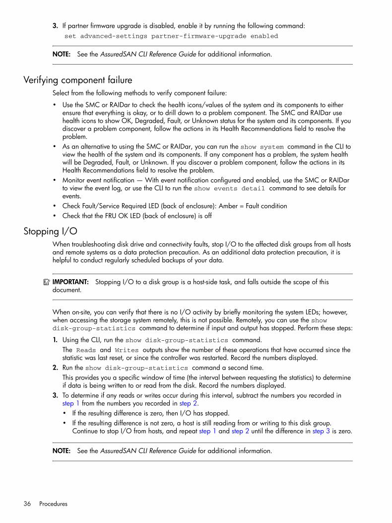
36 Procedures
3. If partner firmware upgrade is disabled, enable it by running the following command:set advanced-settings partner-firmware-upgrade enabled
NOTE: See the AssuredSAN CLI Reference Guide for additional information.
Verifying component failureSelect from the following methods to verify component failure:
• Use the SMC or RAIDar to check the health icons/values of the system and its components to either ensure that everything is okay, or to drill down to a problem component. The SMC and RAIDar use health icons to show OK, Degraded, Fault, or Unknown status for the system and its components. If you discover a problem component, follow the actions in its Health Recommendations field to resolve the problem.
• As an alternative to using the SMC or RAIDar, you can run the show system command in the CLI to view the health of the system and its components. If any component has a problem, the system health will be Degraded, Fault, or Unknown. If you discover a problem component, follow the actions in its Health Recommendations field to resolve the problem.
• Monitor event notification — With event notification configured and enabled, use the SMC or RAIDar to view the event log, or use the CLI to run the show events detail command to see details for events.
• Check Fault/Service Required LED (back of enclosure): Amber = Fault condition• Check that the FRU OK LED (back of enclosure) is off
Stopping I/OWhen troubleshooting disk drive and connectivity faults, stop I/O to the affected disk groups from all hosts and remote systems as a data protection precaution. As an additional data protection precaution, it is helpful to conduct regularly scheduled backups of your data.
IMPORTANT: Stopping I/O to a disk group is a host-side task, and falls outside the scope of this document.
When on-site, you can verify that there is no I/O activity by briefly monitoring the system LEDs; however, when accessing the storage system remotely, this is not possible. Remotely, you can use the show disk-group-statistics command to determine if input and output has stopped. Perform these steps:
1. Using the CLI, run the show disk-group-statistics command.The Reads and Writes outputs show the number of these operations that have occurred since the statistic was last reset, or since the controller was restarted. Record the numbers displayed.
2. Run the show disk-group-statistics command a second time.This provides you a specific window of time (the interval between requesting the statistics) to determine if data is being written to or read from the disk. Record the numbers displayed.
3. To determine if any reads or writes occur during this interval, subtract the numbers you recorded in step 1 from the numbers you recorded in step 2.• If the resulting difference is zero, then I/O has stopped.• If the resulting difference is not zero, a host is still reading from or writing to this disk group.
Continue to stop I/O from hosts, and repeat step 1 and step 2 until the difference in step 3 is zero.
NOTE: See the AssuredSAN CLI Reference Guide for additional information.

AssuredSAN 4004 Series FRU Installation and Replacement Guide 37
Shutting down a controller moduleShutting down the Storage Controller in a controller module ensures that a proper failover sequence is used, which includes stopping all I/O operations and writing any data in write cache to disk. If the Storage Controller in both controller modules is shut down, hosts cannot access the system’s data. Perform a shut down before you remove a controller module from an enclosure, or before you power off its enclosure for maintenance, repair, or a move.
CAUTION: You can continue to use the CLI when either or both Storage Controllers are shut down, but information shown might be invalid.
Use the SMC, RAIDar, or the CLI to perform a shut down.
Using the SMC or RAIDarTo shut down using the SMC (v3):
1. Sign-in to the SMC using default user manage and password !manage.If the default user or password—or both—have been changed for security reasons, enter the secure login credentials instead of the system defaults shown.
2. In the System topic, select Restart System.The Controller Restart and Shut Down panel opens.
3. Select the Shut Down operation, which automatically selects the controller type Storage.4. Select the controller module to shut down: A, B, or both.5. Click OK. A confirmation panel appears.6. Click Yes to continue; otherwise, click No. If you clicked Yes, a message describes shutdown activity.
NOTE: If an iSCSI port is connected to a Microsoft Windows host, the following event is recorded in the Windows event log: Initiator failed to connect to the target.
To shut down using RAIDar (v2):
1. Sign-in to RAIDar using default user manage and password !manage.If the default user or password—or both—have been changed for security reasons, enter the secure login credentials instead of the system defaults shown above.
2. In the Configuration View panel, right-click the system and select Tools > Shut Down or Restart Controller.The Shut Down or Restart Controller panel appears.
3. In the Shut Down or Restart Controller panel, set the options:• Operation: select Shut down.• Controller type: select Storage.• Within the Controller field, select A, B, or Both.
4. Click Shut down now. A confirmation dialog appears.5. Click Yes to continue; otherwise, click No. If you clicked Yes, a second confirmation dialog appears.6. Click Yes to continue; otherwise, click No. If you clicked Yes, a message describes shutdown activity.
NOTE: If an iSCSI port is connected to a Microsoft Windows host, the following event is recorded in the Windows event log: Initiator failed to connect to the target.
NOTE: See the AssuredSAN Storage Management Guide for additional information.

38 Procedures
Using the CLIYou can set a CLI preference to use v3 commands to manage virtual storage or to use v2 commands to manage linear storage. See TIP bullets regarding CLI “default management mode” and “current management mode” page 35.
1. Log-in to the CLI using default user manage and password !manage.If the default user or password—or both—have been changed for security reasons, enter the secure login credentials instead of the system defaults shown above.
2. In a dual-controller system, verify that the partner controller is online by running the command:show controllers
3. Shut down the failed controller—A or B—by running the command:shutdown a or shutdown b
The blue OK to Remove LED (back of enclosure) illuminates to indicate that the controller module can be safely removed.
4. Illuminate the identification LED of the enclosure that contains the controller module to remove by running the command:set led enclosure 0 on
NOTE: See the AssuredSAN CLI Reference Guide for additional information.
Removing a controller module or expansion module
IMPORTANT:• In a single-controller configuration, if you desire to transport CompactFlash to a replacement
controller, remove the controller module only after the cache is copied to CompactFlash, which is indicated by the Cache Status LED being off (see Transporting CompactFlash on page 40).
• In a single-controller environment, you must stop I/O and power off the enclosure before replacing the controller module.
• In a dual-controller environment, you may hot-replace a single controller module in an operational enclosure, provided you first shut down the faulty controller using the SMC, RAIDar, or the CLI.
• In a dual-controller environment—if replacing both controller modules—you must adhere to the instructions provided in Before you begin on page 34.
See CAUTION bullets regarding “electrostatic discharge” and “anti-static protection” page 30.
NOTE: Within these procedures, illustrations featuring controller module face plates are generic. They do not show host interface ports, and they pertain to all 4004 Series controller module models. For illustrations of model-specific controller face plates, see the AssuredSAN 4004 Series Setup Guide.
Illustrations in the controller module replacement procedures show rear panel views of the enclosure, and IOMs are properly aligned for insertion into the rear panel of the enclosure. 1. Verify that you have successfully shut down the controller module using the SMC, RAIDar, or the CLI.2. Locate the enclosure whose Unit Locator LED (front right ear) is illuminated, and within the enclosure,
locate the controller module whose OK to Remove LED is blue (rear panel).3. Disconnect any cables connected to the controller.
Label each cable to facilitate re-connection.4. Turn the thumbscrews counterclockwise until they disengage from the controller (see Figure 23 on
page 39).

AssuredSAN 4004 Series FRU Installation and Replacement Guide 39
Figure 23 Disengaging a controller module
5. Press both latches downward to disconnect the controller module from the midplane (see Figure 24).
Figure 24 Extracting a controller module
6. Pull the controller module straight out of the enclosure such that the controller module remains level during removal (see Figure 25 — 2U chassis) or (Figure 26 on page 40 — 4U chassis).
Figure 25 Removing a controller module (2U)
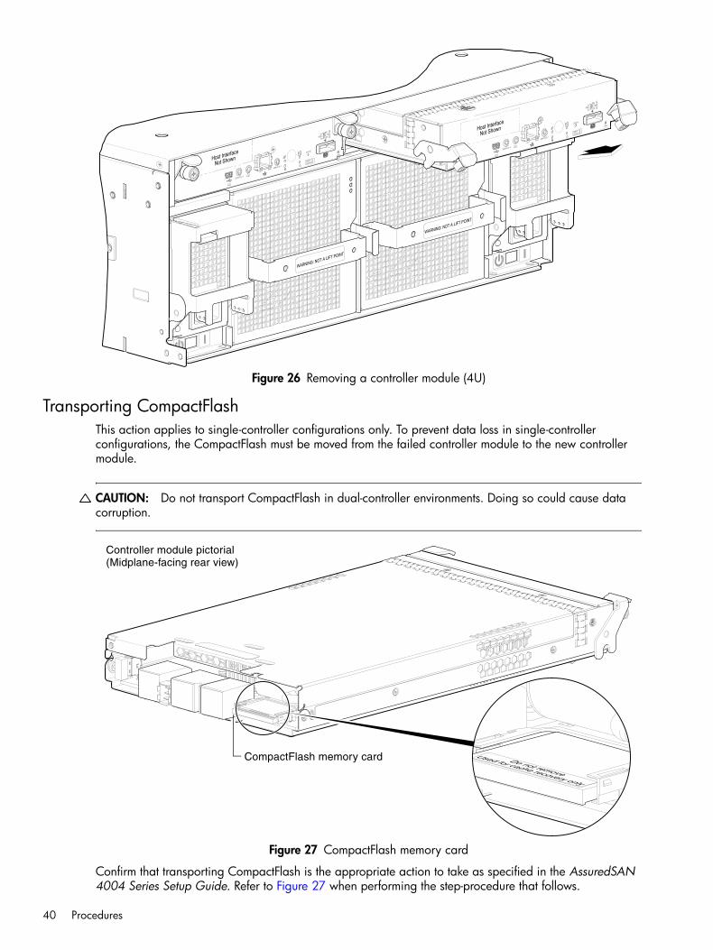
40 Procedures
Figure 26 Removing a controller module (4U)
Transporting CompactFlashThis action applies to single-controller configurations only. To prevent data loss in single-controller configurations, the CompactFlash must be moved from the failed controller module to the new controller module.
CAUTION: Do not transport CompactFlash in dual-controller environments. Doing so could cause data corruption.
Figure 27 CompactFlash memory card
Confirm that transporting CompactFlash is the appropriate action to take as specified in the AssuredSAN 4004 Series Setup Guide. Refer to Figure 27 when performing the step-procedure that follows.
Do not remove
Used for cache recovery only
Controller module pictorial
CompactFlash memory card
(Midplane-facing rear view)

AssuredSAN 4004 Series FRU Installation and Replacement Guide 41
See CAUTION bullets regarding “electrostatic discharge” and “anti-static protection” on page 30.
1. Locate the CompactFlash memory card at the midplane-facing end of the failed controller module.2. Grip the CompactFlash memory card and carefully pull it from the slot in the failed controller module.3. Label the CompactFlash memory card as Data, and set it aside for safekeeping.4. Locate the replacement controller module, and carefully remove its installed CompactFlash memory card.
Take care not to confuse this disc with the one labeled Data.5. Align the CompactFlash memory card labeled Data for insertion into the replacement controller
module—then insert it into the slot—and push it forward until seated in place.
Installing a controller module or expansion module
TIP: You can install a controller module into an enclosure that is powered on, provided you wait 60 seconds after removing the old controller module. Check controller and midplane power connectors before inserting the new controller module into the enclosure.
See CAUTION bullets regarding “electrostatic discharge” and “anti-static protection” on page 30.
1. Loosen the thumbscrews; press the latches downward (see Figure 28 or Figure 29 on page 42).2. Ensuring that the controller module is level, slide it into the enclosure as far as it will go (1).
A controller module that is only partially-seated will prevent optimal performance of the controller enclosure. Verify that the controller module is fully-seated before continuing.
3. Press the latches upward to engage the controller module (2); turn the thumbscrews clockwise until finger-tight.
4. Reconnect the cables.
NOTE: See the AssuredSAN 4004 Series Setup Guide for cabling information.
Figure 28 Inserting a controller module (2U)
IMPORTANT: In a dual-controller system in which PFU is enabled, when you update firmware on one controller, the system automatically updates the partner controller.
2
2
1

42 Procedures
Figure 29 Inserting a controller module (4U)
Verifying component operationAfter replacing the controller module, verify that the FRU OK LED (rear panel) illuminates green, indicating that the controller has completed initializing, and is online/operating normally. It may take two to five minutes for the replacement controller to become ready. If you are replacing either controller module, and PFU is enabled, you may need to wait 30 minutes to ensure that the two controllers—with their respective ownership of the disk groups—have enough time to fully stabilize.
IMPORTANT: Use the SMC, RAIDar, or the CLI to perform a restart only if necessary. For more information, see the topic about restarting controllers in the Storage Management Guide.
Using the SMC or RAIDarTo restart the controller using the SMC (v3):
1. Sign-in to the SMC using default user manage and password !manage.If the default user or password—or both—have been changed for security reasons, enter the secure login credentials instead of the system defaults shown.
2. In the System topic, select Restart System.The Controller Restart and Shut Down panel opens.
3. Select the Restart operation.4. Select the controller type to restart: Management or Storage.5. Select the controller module to shut down: A, B, or both.6. Click OK. A confirmation panel appears.7. Click Yes to continue; otherwise, click No. If you clicked Yes, a message describes shutdown activity.
NOTE: If an iSCSI port is connected to a Microsoft Windows host, the following event is recorded in the Windows event log: Initiator failed to connect to the target.
To restart the controller using RAIDar (v2):
1
2
2

AssuredSAN 4004 Series FRU Installation and Replacement Guide 43
1. Sign-in to RAIDar using default user manage and password !manage.If the default user or password—or both—have been changed for security reasons, enter the secure login credentials instead of the system defaults shown above.
2. In the Configuration View panel, right-click the system and select Tools > Shut Down or Restart Controller.
3. In the main panel, set the options:• Operation: Select Restart.• Controller Type: Select the controller type to restart: Management or Storage.• Controller: Select the controller module to restart: A, B, or Both.
4. Click Restart now. A confirmation panel appears.5. Click Yes to continue; otherwise, click No. If you click Yes, a second confirmation diagram appears.6. Click Yes to continue; otherwise, click No. If you click Yes, a message describes restart activity.
NOTE: If an iSCSI port is connected to a Microsoft Windows host, the following event is recorded in the Windows event log: A connection to the target was lost, but Initiator successfully reconnected to the target.
Using the CLIYou can set a CLI preference to use v3 commands to manage virtual storage or to use v2 commands to manage linear storage. See TIP bullets regarding CLI default management mode and current management mode on page 35.
If the enclosure’s Unit Locator LED is on, run the following command to turn it off:
set led enclosure 0 off
If the Fault/Service Required LED is amber, the controller module has not gone online, and likely failed its self-test. Put the module online by restarting the controller, or by checking the event log for errors.
To restart the Management Controller (A or B), run the following command:
restart mc a or restart mc b or restart mc bothTo restart the Storage Controller (A or B), run the following command:
restart sc a or restart sc b or restart sc both
TIP: See the Setup Guide for descriptions of model-specific LEDs.
Updating firmwareYou can view the current versions of firmware in controller modules, expansion modules (in drive enclosures), and disks, and you can also install new firmware versions.
TIP: To ensure success of an online update, select a period of low I/O activity. This helps the update complete as quickly as possible and avoids disruptions to hosts and applications due to timeouts. Attempting to update a storage system that is processing a large I/O-intensive batch job will likely cause hosts to lose connectivity with the storage system.
Whereas 4U56 and 2U48 enclosures are configured with dual-IOMs, a 2U24 or 2U12 controller enclosure can contain one or two controller modules. In a dual-controller system, both I/O modules (IOMs) should run the same firmware version. Storage systems in a replication set must run compatible firmware versions. You can update the firmware in each IOM by loading a firmware file obtained from the enclosure vendor.

44 Procedures
If you have a dual-controller system and the PFU option is enabled, when you update one controller, the system automatically updates the partner controller. If PFU is disabled, after updating firmware on one controller, you must log into the partner controller’s IP address and perform this firmware update on that controller also.
NOTE: If a vdisk (v2) or disk group (v3) is quarantined, firmware update is not permitted due to the risk of losing unwritten data that remains in cache for the vdisk or disk group. Before you can update firmware, you must resolve the problem causing the quarantine, as described in the Storage Management Guide, online help, or the CLI Reference Guide (see dequarantine CLI command).
For best results, the storage system should be in a healthy state before starting firmware update. You can update firmware using the SMC, RAIDar, or by using FTP (File Transfer Protocol). See the Storage Management Guide for more information.
IMPORTANT: See the topic about updating firmware within the AssuredSAN Storage Management Guide before performing a firmware update.
Accessing drawersUnlike 2U12 and 2U24 enclosures, the high-density 2U48 and 4U56 chassis house disk drive modules within drive slots in the drawers. For high-density enclosures, you interact with drawers to obtain access to disks and disk drive slots.
• For information about 2U16 drawers, see Accessing a 2U16 drawer.• For information about 4U28 drawers, see Accessing a 4U28 drawer on page 46.
Accessing a 2U16 drawerThe 2U48 enclosure includes two different drawers; one for the left (Drawer 0) and middle (Drawer 1) drawers, and one for the right (Drawer 2) drawer. See Drawer description for 2U48 chassis appendix for a summary overview of disk slot numbering and drawer-loading requirements for 2U48 enclosures.
Opening and closing a 2U16 drawerYou can open a drawer for visual inspection of disks while the drawer is in operation. Before accessing the drawer via its handle, you must first remove the enclosure bezel (see Removing the enclosure bezel (2U) on page 33). Given that the enclosure bezel is required to provide EMI protection, you should re-attach the bezel to the enclosure after examining the drawer.
1. Using a Torx T15 or straight blade screwdriver, loosen the drawer stop screw on the front face of the drawer (see Loosen the drawer stop screw (2U48) on page 44).Once the screw is loosened, use the outer thumb wheel to unlock the drawer. Do not remove the screw.
Figure 30 Loosen the drawer stop screw (2U48)
1 20
Enclosure front panel with bezel removed showing left (0), middle (1), and right (2) drawers
Loosen screw on target drawer

AssuredSAN 4004 Series FRU Installation and Replacement Guide 45
2. Revolve the drawer handle upwards by 90to enable pulling the drawer outward for viewing disks (see Revolve the handle to drawer-pull position (2U48) on page 45).
Figure 31 Revolve the handle to drawer-pull position (2U48)
3. Face the front of the drawer—and using the handle—pull the drawer outward along the drawer slide until it meets the drawer stop. See Opening and closing a drawer: pull or push drawer along slide (2U48) on page 45.The open drawer that shown in the example is empty.
Figure 32 Opening and closing a drawer: pull or push drawer along slide (2U48)
To close the drawer, simply slide the drawer into the enclosure along the drawer slide until it properly seats in the drawer bay. Take care to ensure there are no loose cable wires protruding beyond the limits of the igus chainflex cable. After closing the drawer, revolve the handle downwards such that it is flush with the drawer front panel—in its stowed position—and re-attach the bezel to the front of the enclosure.
Aligning an AMS or disk module for installation into a 2U16 drawerOnce you have opened the drawer, you can access the disk bays. The enclosure uses an SFF sledded disk positioned to lay on its side—with the disk PCBA facing up—for insertion into the disk slot within the drawer. Each disk is mated to a connector on the drawer PCBA. In the absence of quantity-four disks, the enclosure uses an Air Management Solution (AMS) insert within disk bays to manage air flow within the enclosure, to help maintain optimal operating temperature. A new AMS insert is also available for single disk slots.
NOTE: For more information about AMS inserts, see Air management solution insert on page 49.
90°
The drawer handle functions identically on all drawers.
90°

46 Procedures
Figure 33 Align AMS or disk module for installation into the 2U16 drawer
IMPORTANT: Each disk bay must be populated with either a full complement of four disk drive modules, a disk bay AMS insert (shown above), or a combination of disks and single disk slot AMS inserts (see Figure 38 on page 50). Empty disk slots are disallowed.
Accessing a 4U28 drawerThe 4U56 enclosure includes two different drawers: one for the left drawer bay (Drawer 0), and one for the right drawer bay (Drawer 1). See Drawer description for 4U56 chassis appendix for a summary overview of disk slot numbering and drawer-loading requirements for 4U56 enclosures.
Opening and closing a 4U28 drawerYou can open a drawer for visual inspection of disks while the drawer is in operation. Before accessing the drawer via its handle, you must first remove the enclosure bezel (see Removing the enclosure bezel (4U) on page 33). Given that the enclosure bezel is required to provide EMI protection, you should re-attach the bezel to the enclosure after examining the drawer.
1. Using a Torx T15 or straight blade screwdriver, loosen the two screws securing the handle to the front face of the drawer (see Loosen the drawer stop screw (4U56) on page 47).Once the two screws on the target drawer are loosened, turn the thumbwheel counter-clockwise to disengage the handle from its upright stowed position.
2. Move the drawer toggle to enable the target drawer to travel along the slide.Move the toggle to the right to open Drawer 0 (left drawer); or move the toggle to the left to open Drawer 1 (right drawer).
3. Revolve the drawer handle downwards by 90to enable pulling the drawer outward for viewing disk slots (see Revolve the handle to drawer-pull position (4U56) on page 47).
4. Face the front of the drawer—and using the handle—pull the drawer outward along the drawer slide until it meets the first drawer stop.The second stop is met by using your index fingers to pull the blue clips (located on both sides of the drawer) towards the front of the drawer. Pull the drawer outward until it meets the next drawer stop.
NOTE: Do not pull out a drawer that is fully loaded with disks to the second stop.
Disk
AMS (disk bay)

AssuredSAN 4004 Series FRU Installation and Replacement Guide 47
To close the drawer, simply slide the drawer into the enclosure along the drawer slide until it properly seats in the drawer bay. Take care to ensure that no loose cable wires protrude beyond the limits of the igus chainflex cable. Note that the drawer will lock at the second stop. To release the lock, use your index fingers to pull the blue clips towards the front of the drawer and slide the drawer into the enclosure. After closing the drawer, revolve the handle upwards such that it is flush with the drawer front panel—in stowed position—and tighten the two handle screws. Re-attach the bezel to the front of the enclosure.
Figure 34 Loosen the drawer stop screw (4U56)
Figure 35 Revolve the handle to drawer-pull position (4U56)
DRAWER 0 DRIVES 0 − 27PN: 21−00000590−00−01 rev A
DRAWER 1 DRIVES 28 − 55PN: 21−00000590−00−02 rev A
Drawer toggle moved to right positionallows Drawer 0 to pull forward.
Bird’s eye right view (Drawer 1 hidden)Note:
Loosen screws on target drawer
Enclosure front panel featuringdrawer access components
90°
Drawer handle
Stow pos i t ion
Pu l l pos i t ion
Revolve handle to suit openand close drawer actions.
Enclosure front panel (partial)

48 Procedures
Replacing a disk drive moduleA disk drive module consists of a disk in a sled. Disk drive modules are hot-swappable, which means they can be replaced without halting I/O to the disk groups, or powering off the enclosure. The new disk drive module must be of the same type, and possess capacity equal to or greater than the one being replaced. Otherwise, the storage system cannot use the new disk to reconstruct the disk group.
If one or more disks fail in a disk group and spares of the appropriate size (same or larger) and type (same as the failed disks) are available, the storage system automatically uses the spares to reconstruct the disk group. Disk group reconstruction does not require I/O to be stopped, so volumes can continue to be used while reconstruction is in progress.
If no spares are available, reconstruction does not start automatically. To start reconstruction manually, replace each failed disk and designate each replacement disk as a spare. If you have configured the dynamic spares feature through the CLI, reconstruction will automatically start for linear disk groups. With dynamic spares enabled, if a disk fails and you replace it with a compatible disk, the storage system rescans the bus, finds a new disk, automatically designates it a spare, and starts reconstructing the disk group.
For virtual storage only, reconstruction of all disk groups uses a quick-rebuild feature.
FDE considerationsThe Full Disk Encryption feature available via the management interfaces requires use of self-encrypting drives (SED) which are also referred to as FDE-capable disk drive modules. When installing FDE-capable disk drive modules, follow the same procedures for installing disks that do not support FDE. The exception occurs when you move FDE-capable disk drive modules for one or more disk groups to a different system, which requires additional steps.
The procedures for using the FDE feature, such as securing the system, viewing disk FDE status, and clearing and importing keys are performed using the SMC, RAIDar, or CLI commands (see the 4004 Series content within the Storage Management Guide or CLI Reference Guide for more information).
NOTE: When moving FDE-capable disk drive modules for a disk group, stop I/O to the disk group before removing the disk drive modules. Import the keys for the disks so that the disk content becomes available.
While replacing or installing FDE-capable disk drive modules, consider the following:
• If you are installing FDE-capable disks drive modules that do not have keys into a secure system, the system will automatically secure the disks after installation. Your system will associate its existing key with the disks, and you can transparently use the newly-secured disks.
• If the FDE-capable disk drive modules originate from another secure system, and contain that system’s key, the new disks will have the Secure, Locked status. The data will be unavailable until you enter the passphrase for the other system to import its key. Your system will then recognize the metadata of the disk group and incorporate it. The disks will have the status of Secure, Unlocked and their contents will be available:• To view the FDE status of disks, use the SMC, RAIDar, or the show fde-state CLI command.• To import a key and incorporate the foreign disks, use he SMC, RAIDar, or the set
fde-import-key CLI command.
NOTE: If the FDE-capable disks contain multiple keys, you will need to perform the key importing process for each key to make the content associated with each key become available.

AssuredSAN 4004 Series FRU Installation and Replacement Guide 49
• If you do not want to retain the disks’ data, you can repurpose the disks. Repurposing disks deletes all disk data, including lock keys, and associates the current system’s lock key with the disks.To repurpose disks, use the SMC, RAIDar, or the set disk CLI command.
• You need not secure your system to use FDE-capable disks. If you install all FDE-capable disks into a system that is not secure, they will function exactly like disks that do not support FDE. As such, the data they contain will not be encrypted. If you decide later that you want to secure the system, all of the disks must be FDE-capable.
• If you install a disk module that does not support FDE into a secure system, the disk will have the Unusable status and will be unavailable for use.
• If you are re-installing your FDE-capable disk drive modules as part of the process to replace the chassis-and-midplane FRU, you must insert the original disks and re-enter their FDE passphrase.
Air management in disk drive slotsAir management modules are used with 2U12 and 2U24 enclosures. Air management solution inserts are used with 2U48 enclosures. The 4U56 enclosure does not require use of an air management device in disk drive slots.
Air management modules2U12 and 2U24 enclosures use air management modules for empty disk drive slots. An air management module looks like a disk drive module; however, it is an empty box—also known as a blank—and it is used to maintain optimal air flow for proper cooling within the enclosure. Air management modules are installed in slots missing disk drive modules. If you must remove a disk drive module, but cannot immediately replace it, you must either leave the faulty module in place, or insert an air management module in its place.
• The blank is installed using the same procedure as Installing a disk drive module (2U12/2U24) on page 55.
• The blank is removed using the same procedure as Removing a disk drive module (2U12/2U24) on page 52.
Air management solution insert2U48 enclosures use air management solution (AMS) inserts. An AMS insert—also known as a blank—is a plastic insert that is used in lieu of disk drive modules within a disk drive bay, or within an individual disk drive slot. Both the disk bay AMS (see Figure 36 on page 50) and the single disk drive slot AMS (see Figure 38 on page 50) are used to maintain optimal air flow for proper cooling within the enclosure.
If you must remove a disk drive module, but cannot immediately replace it, you must either leave the faulty module in place, or arrange to replace it with an AMS.
Familiarize yourself with the disk drive module replacement procedures in this subsection before replacing a faulty disk with another disk drive module; replacing a faulty disk with a single drive slot AMS; or replacing a multiple of four disk drive modules in a given bay with a disk bay AMS.
To access disk slots in the drawer bays, you must first do the following:
• Remove the enclosure bezel (see Removing the enclosure bezel (2U) on page 33). • Pull the drawer outward as described in Opening and closing a 2U16 drawer on page 44.

50 Procedures
Installing an AMS into a 2U16 drawerRefer to Figure 36 when orienting the AMS for insertion into the target drawer. If you are installing into the left drawer or middle drawer, refer to the illustration on the left when performing this step-procedure. If you are installing into the right drawer, refer to the illustration on the right when performing this step-procedure.
Figure 36 Orient the AMS for installation (2U48)
1. Squeeze the latch release flanges together—so that the locking-nib will clear the sheet metal bay wall—and insert the AMS into the target disk bay.
2. Verify that the AMS is firmly seated in place.The installed disk drive modules and AMS insert should now appear as shown in the sectioned cutaway views of the respective drawers in Figure 37.
Figure 37 Secure the AMS into the disk bay (2U48)
If using the new single disk slot AMS insert shown in Figure 38, the insertion steps are essentially the same as those described for Figure 36 and Figure 37 above; however, they pertain to a single disk slot rather than a disk bay (four vertically-contiguous disk slots).
Figure 38 AMS insert for a single disk slot (2U48)
Align AMS for insertion into disk bay
Right drawerLeft or middle drawer
Right drawerLeft or middle drawer
The single disk slot AMS insertis slated to replace the diskbay AMS insert over time.

AssuredSAN 4004 Series FRU Installation and Replacement Guide 51
IMPORTANT: Each disk bay must be populated with either an full complement of four disk drive modules, a disk bay AMS (shown above), or a combination of disks and single disk slot AMS inserts (see Figure 38). Empty disk slots are disallowed.
Removing an AMS from a 2U16 drawerRefer to Figure 39 when removing the AMS from the target drawer. If you are extracting from the left or middle drawer, refer to the illustration on the left when performing the step procedure. If you are extracting from the right drawer, refer to the illustration on the right when performing this step-procedure.
Figure 39 Remove the AMS from the disk bay (2U48)
1. Squeeze the latch release flanges together—so that the locking-nib will clear the sheet metal bay wall—and extract the AMS from the target disk bay.
2. Pull the AMS insert straight out of the disk bay as shown in Figure 39 on page 51.
If using the new single disk slot AMS insert shown in Figure 38 on page 50, the insertion steps are essentially the same as those described for Figure 39 on page 51; however, they pertain to a single disk slot rather than a disk bay (four vertically-contiguous disk slots).
Before you begin
CAUTION: Removing a disk drive module impacts the airflow and cooling ability of the enclosure. If the internal temperature exceeds acceptable limits, the enclosure may overheat and automatically shut down or restart. To avoid potential overheating, wait 20 seconds to allow the internal disks to stop spinning, then insert the new disk drive module.
See CAUTION bullets regarding “electrostatic discharge” and “anti-static protection” on page 30.
Verifying component failureBefore replacing a disk, perform the following steps to ensure that you have correctly identified the module requiring removal and replacement.
CAUTION: Failure to identify the correct disk drive module could result in data loss if the wrong disk is removed from the enclosure. You can observe disk component health using the SMC or RAIDar, or via line-of-sight observation of the racked components.
When a disk drive fault occurs, the failed disk’s fault indicator LED, located on the enclosure’s front panel, illuminates solid amber (see the AssuredSAN 4004 Series Setup Guide for a description of LEDs and disk drive slot numbering for your enclosure). You can determine from visual inspection which disk in the enclosure is experiencing a fault/failure using the fault LED for your disk type.
Remove AMS from disk bay
Right drawerLeft or middle drawer

52 Procedures
NOTE: Bezel removal and drawer access (high-density models) may be required for replacing disks.• See Figure 21 on page 32 for 2U enclosure bezel alignment.• See Figure 22 on page 33 for 4U enclosure bezel alignment.• See Accessing a 2U16 drawer on page 44 for 2U48 models.• See Accessing a 4U28 drawer on page 46 for 4U56 models.
Alternatively, you can observe disk component health using management interfaces to verify component failure or component operation (see Using management interfaces on page 88 for more information).
Removing a disk drive module (2U12/2U24)1. Follow one of two sub-steps below, according to your product disk drive module type (see Figure 40 on
page 52):a. SFF disk (stands on edge) — Squeeze the latch release flanges together to disengage the disk drive
module, and swing the pivoting portion of the latch upwards by 45(see Figure 40 and Figure 41 on page 53).
b. LFF disk (lays on side) — Slide the release latch to the left to disengage the disk drive module (see Figure 40 on page 52).Moving the latch to the left will provide a clicking sound and cause the spring to move its position inside the chassis, partially ejecting the disk from its installed position within the disk drive slot.
Figure 40 Disengaging a disk drive module (2U24/2U12)
2. Wait 20 seconds for the internal disks to stop spinning.3. Follow one of the two sub-steps below, according to your product disk drive type (see Figure 41):
a. SFF disk — Firmly grasp the front of the plastic sled, and pull the disk drive module straight out of the chassis, taking care not to drop the module.
b. LFF disk — Once the disk drive module partially ejects from the slot, grasp the module firmly, and carefully pull it straight out of the chassis slot. Take care not to drop the module.
SFF 2.5" disk or blank LFF 3.5" disk or blank

AssuredSAN 4004 Series FRU Installation and Replacement Guide 53
Figure 41 Removing a disk drive module (2U24/2U12)
Removing a disk drive module (2U48)To access disk slots in the drawer bays, you must first do the following:
• Remove the enclosure bezel (see Removing the enclosure bezel (2U) on page 33). • Pull the drawer outward as described in Opening and closing a 2U16 drawer on page 44.
IMPORTANT: Drawer and disk slot numbering are described pictorially on the label located on the top of each drawer. Disk slot numbering for drawers 0 (left) and 1 (middle) begins at the front of the drawer and moves inward (column-by-column) along the z-axis; whereas disk slot numbering for drawer 2 (right) begins at the rear of the drawer and moves outward (column-by-column).
IMPORTANT: Familiarize yourself with FDE considerations on page 48 before performing this step-procedure.
If you are removing a disk drive module from the left drawer or middle drawer, refer to the illustrations on the left when performing this step-procedure. If you are removing a disk drive module from the right drawer, refer to the illustrations on the right when performing this step-procedure.
IMPORTANT: Disk module removal guidelines • Stop I/O to the disk (see Stopping I/O on page 36).• Remove only one disk drive module at a time: concurrent/multiple disk module removal is not allowed.• Remove the disk module (per step procedure)—wait 30 seconds—before removing another disk.
1. Squeeze the latch release flanges together to release the locking-nib on the right side of the sled from the drawer cage wall, and disengage the disk drive module from its connector on the drawer PCBA (see illustration for appropriate drawer in Figure 42).
Extract SFF disk or blankExtract LFF disk or blank

54 Procedures
Figure 42 Disengaging a disk drive module (2U48)
2. Wait 20 seconds for the internal disks to stop spinning. 3. Firmly grasp the front of the plastic sled, and pull the disk drive module straight out of the chassis,
taking care not to drop the module (see illustration for appropriate drawer in Figure 43).
Figure 43 Removing a disk drive module (2U48)
Removing a disk drive module (4U56)To access disk slots in the drawer bays, you must first do the following:
• Remove the enclosure bezel (see Removing the enclosure bezel (4U) on page 33). • Pull the drawer outward as described in Opening and closing a 4U28 drawer on page 46.
IMPORTANT: Drawer and disk slot numbering are described pictorially on the label located on the exterior wall of each drawer. Disk slot numbering for drawers 0 (left) and 1 (right) begins at the front of the drawer and moves inward (row-by-row) along the x-axis.
IMPORTANT: Familiarize yourself with FDE considerations on page 48 before performing this step-procedure.
IMPORTANT: Disk module removal guidelines:• Stop I/O to the disk (see Stopping I/O on page 36).• Remove only one disk drive module at a time: concurrent/multiple disk module removal is not allowed.• Remove the disk module (per step procedure)—wait 30 seconds—before removing another disk.
1. Using your index finger, slide the release latch—located in the upper pocket on the face of the disk drive module—forward to disengage the disk drive module (see detail inset view in Figure 44 on page 55).
Disengage and extract the SFF 2.5" disk drive module
Right drawerLeft or middle drawer
Remove the SFF 2.5" disk drive module
Right drawerLeft or middle drawer

AssuredSAN 4004 Series FRU Installation and Replacement Guide 55
Moving the latch forward will provide a clicking sound and cause the spring to move its position inside the drawer cage, partially ejecting the disk from its installed position within the disk drive slot.
Figure 44 Remove a disk from a drawer slot (4U56)
2. Wait 20 seconds for the internal disks to stop spinning.3. Once the disk drive module partially ejects from the slot, grasp the module firmly, and carefully pull it
straight out of the drawer slot. Take care not to drop the module.
Installing a disk drive module (2U12/2U24)
IMPORTANT: Familiarize yourself with FDE considerations on page 48 before performing this step-procedure to mitigate the potential for unusable installed disks.
1. Follow one of the two sub-steps below, according to your product disk drive module type:a. SFF disk — Squeeze the latch release flanges together, and then pull the latch, rotating it upward
until it is fully open (see Figure 40 on page 52 and Figure 41 on page 53).b. LFF disk — No action required.
Proceed to step 2 below.2. Follow one of the two sub-steps below, according to your product disk drive module type:
a. SFF disk — With the LEDs oriented to the bottom, slide the disk drive module into the drive slot as far as it will go (see left illustration in Figure 45).
b. LFF disk — With the LEDs oriented to the left, slide the disk drive module into the drive slot as far as it will go (see right illustration in Figure 45).
Figure 45 Installing a disk drive module (2U24/2U12)
Release latch
Insert SFF disk or blankInsert LFF disk or blank

56 Procedures
3. Follow one of the two sub-steps below, according to your product’s disk drive type:a. SFF disk — Rotate the latch downward until it clicks closed to firmly seat the disk drive module in the
enclosure midplane.b. LFF disk — Verify that you have inserted the disk drive module into the slot as far as it will go, to
ensure that the module is firmly seated in the enclosure midplane.The installed disk drive module should now appear as shown in Figure 40 on page 52.
NOTE: Allow at least 30 seconds to elapse when jointly completing the “Removing a disk drive module” and “Installing a disk drive module” procedures.
4. To complete this procedure, see Completing the disk module installation on page 58.
Installing a disk drive module (2U48)To access disk slots in the drawer bays, you must first do the following:
• Remove the enclosure bezel (see Attaching the enclosure bezel (2U) on page 33). • Pull the drawer outward as described in Opening and closing a 2U16 drawer on page 44.
IMPORTANT: Familiarize yourself with FDE considerations on page 48 before performing this step-procedure to mitigate the potential for unusable installed disks.
IMPORTANT: Disk module installation guidelines • Install only one disk drive module at a time: concurrent/multiple disk module insertions are not allowed.• Install the disk module (per step procedure)—wait 45 seconds—before installing another disk module.
The enclosure uses an SFF sledded disk positioned to lay on its side—with the disk PCBA facing up—for insertion into the disk slot within the drawer. Each disk is mated to a connector on the drawer PCBA.
If you are installing a disk drive module in the left drawer or middle drawer, refer to illustrations on the left when performing the step-procedure. If you are installing a disk drive module in the right drawer, refer to illustrations on the right when performing this step-procedure.
1. While supporting the bottom of the disk drive module with one hand (disk PCBA should be facing up and latch release flanges should be facing out)—align the disk drive module for insertion into the target disk slot (see illustration for appropriate drawer in Figure 46).
2. Using your other hand, squeeze the latch release flanges together—so that the locking-nib will clear the sheet metal bay wall—and insert the disk drive module into the target slot (see illustration for appropriate drawer in Figure 46).
Figure 46 Aligning the disk drive module (2U48)
3. Gently push the disk drive module into the slot until it latches in place.
Align the SFF 2.5" disk drive module
Right drawerLeft or middle drawer

AssuredSAN 4004 Series FRU Installation and Replacement Guide 57
The installed disk drive module should now appear as shown (see illustration for appropriate drawer in Figure 47 on page 57). Wait 45 seconds before installing another disk.
Figure 47 Installing a disk drive module (2U48)
NOTE: Allow at least 30 seconds to elapse when jointly completing the “Removing a disk drive module” and “Installing a disk drive module” procedures.
4. To complete this procedure, see Completing the disk module installation on page 58.
Installing a disk drive module (4U56)To access disk slots in the drawer bays, you must first do the following:
• Remove the enclosure bezel (see Removing the enclosure bezel (4U) on page 33). • Pull the drawer outward as described in Opening and closing a 4U28 drawer on page 46.
IMPORTANT: Familiarize yourself with FDE considerations on page 48 before performing this step-procedure to mitigate the potential for unusable installed disks.
IMPORTANT: Disk module installation guidelines:• Install only one disk drive module at a time: concurrent/multiple disk module insertions are not allowed.• Install the disk module (per step procedure)—wait 45 seconds—before installing another disk module.
IMPORTANT: If you are completely filling a drawer with disk modules, populate from back row to front row, while installing disks into the slots. Provide adequate support for the weight of the extended drawer as you install the disks.If you are installing disk modules to partially fill a drawer, you must install a minimum of 14 disk modules, and they must be placed in contiguous slots closest to the front of the drawer.
The enclosure uses an LFF sledded disk positioned to stand on end, for insertion into the disk slot within the drawer. Each disk is mated to a connector on the drawer PCBA.
1. With the disk module standing on end—and the LEDs oriented to the left—insert the disk module into the vertically-aligned disk slot. Notches on the inside of the drawer will help guide the disk to the correct position and seat the disk into the connector on the drawer PCBA.
Right drawerLeft or middle drawer
Secure the SFF 2.5" disk drive module into the disk slot

58 Procedures
2. Verify that you have inserted the disk module into the slot as far as it will go. A spring in the drawer slot will provide a resistive force when mating the drive to the connector. This will ensure that the module is firmly seated in the drawer PCBA.
.
Figure 48 Install a disk into a drawer slot (4U56)
NOTE: Allow at least 30 seconds to elapse when jointly completing the “Removing a disk drive module” and “Installing a disk drive module” procedures.
3. To complete this procedure, see Completing the disk module installation on page 58.
Completing the disk module installationIf using the SMC, execute steps 1— 3 to complete this procedure. If using RAIDar, execute steps 4 and 5 to complete this procedure. If using the CLI, execute steps 6 and 7 to complete this procedure.
IMPORTANT: If you install an empty disk and intend to use it as a spare, the disk must be enabled as a spare in order for this procedure to be complete. Spares can be managed using the SMC, RAIDar, or the CLI.
Using the SMC (v3):
1. Sign in to the SMC (use default user manage and password !manage, or the appropriate username and password if they have been changed).
2. Click the System topic. The System panel opens.3. Click the Table tab to determine whether the health of the new disk is OK. If the health is OK, then the
disk drive module installation process is complete. If the health is not OK, then hover over the disk to display details about it, such as Status and Health Recommendations.
Using RAIDar (v2):
4. Sign in to RAIDar (use default user manage and password !manage, or the appropriate username and password if they have been changed).
5. View the System Overview panel to determine whether the health of the new disk is OK. If the health is OK, then the disk drive module installation process is complete. If the health is not OK, then in the Configuration View panel, select the enclosure that the new disk is in to display the Enclosure Overview panel, and select the disk to view details about it, such as Status and Health Recommendations.
Using the CLI:
You can set a CLI preference to use v3 commands to manage virtual storage or to use v2 commands to manage linear storage. See the TIP bullets regarding CLI default management mode and current management mode on page 35.

AssuredSAN 4004 Series FRU Installation and Replacement Guide 59
6. Log in to the CLI (use default user manage and password !manage, or the appropriate username and password if they have been changed).
7. To view information about disks, run the following command:show disks <disk-ID>
Disks are specified by enclosure ID and slot number. Enclosure IDs increment from 0. Disk IDs increment from 0 in each enclosure (e.g., show disks 0.7). Entering the command shown above will display the disk health for the disk residing in slot number 7 of enclosure number 0 (i.e., the controller enclosure). If health is not OK, the command output will also display recommended actions.
Determine if a disk is missingYou can determine whether a disk is missing by using management interfaces.
Using the SMC or RAIDarTo determine whether a disk is missing by using the SMC (v3):
1. Sign-in to the SMC using default user manage and password !manage.If the default user or password—or both—have been changed for security reasons, enter the secure login credentials instead of the system defaults shown above.
2. Click the System topic. The System panel opens.• Select the Front tab to display a pictorial representation of disks within slots, and hover over
individual disks to view the metadata such as location, usage, tier, type, and size.• You can hover over enclosure ears to see metadata for specific enclosures in the system.• Select the Table tab to display a tabular view of information about physical components in the
system.3. Using the Front and Table views, look for gaps in the disk location sequence to determine if a disk is
missing.
To determine whether a disk is missing by using RAIDar (v2):
1. Sign-in to RAIDar using default user manage and password !manage.If the default user or password—or both—have been changed for security reasons, enter the secure login credentials instead of the system defaults shown above.
2. In the Configuration View panel, right-click the appropriate enclosure under Physical.• Select the Front Graphical tab to display a pictorial representation of disks within slots, and the
supporting enclosure table showing properties and values.• Select the Front Tabular tab to display the Enclosure’s Front View data table and supporting
enclosure table showing properties and values.3. Using the graphical and tabular views, look for gaps in the disk location sequence to determine if a
disk is missing.
Using the CLIYou can set a CLI preference to use v3 commands to manage virtual storage or to use v2 commands to manage linear storage. See TIP bullets regarding CLI default management mode and current management mode on page 35.
1. Log-in to the command-line interface (CLI) using default user manage and password !manage.If the default user or password—or both—have been changed for security reasons, enter the secure login credentials instead of the system defaults shown above.
2. To determine location of a missing or faulty drive, run the following command:show disks
The command outputs a listing of detected disks’ properties by location. Review the information, and look for gaps in the disk location sequence to determine whether any disks are missing.

60 Procedures
Verifying component operationVerify that the Power/Activity LED—located on the front face of the disk drive escutcheon—is illuminated green. On LFF disks, this is the bottom LED. On SFF disks, this is the left LED. Both sets of LEDs are shown in Figure 45 on page 55.
TIP: See the AssuredSAN 4004 Series Setup Guide for descriptions of disk drive LEDs and other front panel LEDs pertaining to the controller enclosures.
Also see Using management interfaces on page 88 as an alternative to physically observing LEDs to verify component operation.
Replacing a power supply moduleThis section provides procedures for replacing a failed AC or DC power supply module, also referred to as a power supply unit (PSU). Illustrations in power supply module replacement procedures show rear panel views of the enclosure, and PSUs are properly aligned for insertion into the rear panel of the enclosure.
A single PSU is sufficient to maintain operation of the enclosure. You need not halt operations and completely power-off the enclosure when replacing only one PSU; however, a complete shutdown is required if replacing both power supply units.
CAUTION: Power supply FRU replacement activities can cause enclosure cables to disconnect and disks to go offline. Be careful with cabling connections during FRU replacement.
If immediate replacement is necessary during I/O, ensure that all cables are securely fastened, and proceed with caution as you replace the power supply FRU within the controller enclosure. Be very careful if moving a cabled/operational enclosure during the FRU replacement process.
TIP: See Table 9 for additional information about power supply faults and recommended actions.
Before you begin
CAUTION: Removing a power supply unit significantly disrupts the enclosure’s airflow. Do not remove the PSU until you have received the replacement module.
See CAUTION bullets regarding “electrostatic discharge” and “anti-static protection” on page 30.
Verifying component failureYou can observe power supply component health (PSUs, fans) using LEDs, management interfaces, or a combination thereof to verify component failure or component operation (see Using management interfaces on page 88 for more information).
When either a fan or power supply component fails, the SMC or RAIDar provide notification; faults are recorded in the event log; and the PSU’s status LED color changes to amber to indicate a fault condition.
Table 9 describes menu navigation using the SMC (v3) or RAIDar (v2). The shorthand v3 and v2 prefixes are used to distinguish between the GUI product versions supported by 4004 Series enclosures.
Table 9 also references a CLI command. You can set a CLI preference to use v3 commands to manage virtual storage or to use v2 commands to manage linear storage. See TIP bullets regarding CLI default management mode and current management mode on page 35.

AssuredSAN 4004 Series FRU Installation and Replacement Guide 61
Alternatively, you can observe power supply component health (PSUs, fans) using management interfaces to verify component failure or component operation (see Using management interfaces on page 88 for more information).
Power supply units4004 Series enclosures feature two redundant power supplies of the same type. Except for the 2U48 chassis—which supports AC only—enclosures can be equipped with two AC PSUs or two DC PSUs. Each DC power supply features a power switch. AC PSUs provided with the 2U48 and 4U56 chassis also feature a power switch. AC PSUs provided with 2U12 and 2U24 chassis do not have a power switch. Some AC power supplies used with compatible storage enclosures have a power switch, whereas others do not. This characteristic varies by model type and vintage.
• Figure 53 on page 65 shows PSU alignment with the rear panel of a 2U enclosure.• Figure 54 on page 66 shows PSU alignment with the rear panel of a 4U enclosure.
Supported PSUs are described in the following subsections.
IMPORTANT: Many AC power supply units do not have power switches. These PSUs power on when connected to a power source, and power off when disconnected.
Table 9 Power supply faults and recommended actions
Problem Recommended action
Power supply fan warning or failure, or power supply warning or failureEvent code 551 or 168
• v3: Verify that all fans are working using the SMC.Click the System tab within the topics pane and from the System topic, select the Rear tab. Hover over each power supply module to view health attributes.You can also select the Table tab and view health status for power supply modules and other components in tabular form.
• v2: Verify that all fans are working using RAIDar.In the Configuration View, expand Physical, right-click the enclosure and select View > Overview. Select either Rear Graphical or Rear Tabular to view health attributes.
• Optionally, you can verify that all fans are working using the CLI.The show fans command will output health status for fans in the specified enclosure.
• Ensure that the power supply modules are properly seated and secured within their slots.
• Ensure that no slots are left open for more than two minutes. If you must replace the FRU, leave the old module in place until the replacement arrives to maintain optimal airflow and avoid overheating.
Power supply module failure status, or voltage event notificationEvent code 554, 551, or 168
• Verify that the power supply module is powered on. If your power supply module has a power switch, verify that it is switched on.
• Verify that the power cables are securely attached to the power supply module and the appropriate power source.
AC Power Good LED is off Same as above.
DC Voltage/Fan Fault/Service Required LED is illuminated
Replace the power supply module FRU.

62 Procedures
Power cycling procedures vary according to the type of power supply module included with the enclosure. For 2U controller and expansion enclosures configured with AC PSUs that do not have power switches, refer to the procedure described under AC PSU (2U12 and 2U24) on page 62. For procedures pertaining to a) 2U controller enclosures configured with DC PSUs, b) 2U48 controller enclosures, or c) previously installed 2U drive enclosures featuring power switches, see DC and AC PSUs with power switch (2U) on page 63. See AC and DC PSUs with power switch (4U56) on page 64 for power cycling relative to 4U56 enclosures.
NOTE: AC PSUs—with or without a power switch—are compatible with one another in that the two different models can coexist in the same 2U12 or 2U24 enclosure, and are interchangeable, provided they are of the same form factor/physical size and power rating.
4004 Series enclosures support high-capacity (J6G48 and J6G56) drive enclosures in addition to the J6G12 (2U12) and J6G24 (2U24) drive enclosures for adding storage.
See the table topic summarizing drive enclosures supported by controller enclosures within the AssuredSAN 4004 Series Setup Guide for details.
IMPORTANT: The 4U chassis uses an altogether different power supply unit than the model used for 2U enclosures described herein. This applies to both AC and DC PSUs (see AC and DC PSUs with power switch (4U56) on page 64) for additional information.
AC PSU (2U12 and 2U24)Enclosures configured with AC PSUs that do not have a power switch rely on the power cord for power cycling. Connecting the cord from the PSU power cord connector to the appropriate power source facilitates power on; whereas disconnecting the cord from the power source facilitates power off.
Figure 49 AC PSU (2U12/2U24)
Powering off the PSU1. Stop all I/O from hosts to the enclosure (see Stopping I/O on page 36).
TIP: This step is not required for hot-swapping; however, it is required when replacing both PSUs.
2. Use management software to shut down any other system components necessary.Given that power switch shut-off does not apply to this particular power supply model, proceed to disconnecting the AC power cord.
TIP: This step is not required for hot-swapping; however, it is required when replacing both PSUs.
Power cord connect

AssuredSAN 4004 Series FRU Installation and Replacement Guide 63
Given that power switch shut-off does not apply to this particular power supply model, proceed to disconnecting the AC power cord.
Disconnecting an AC power cord1. Disconnect the power cord’s male plug from the power source.2. Disconnect the power cord’s female plug from the power cord connector on the PSU.
NOTE: See Connecting a power cable (2U models) on page 68 for an illustration showing AC power cord connection/disconnection.
DC and AC PSUs with power switch (2U)DC and AC power supplies—each equipped with a power switch—are shown below.
Figure 50 DC and AC PSUs with power switch (2U)
Powering off the PSU1. Stop all I/O from hosts to the enclosure (see Stopping I/O on page 36).
TIP: This step is not required for hot-swapping; however, it is required when replacing both PSUs.
2. Use management software to shut down any other system components necessary.
TIP: This step is not required for hot-swapping; however, it is required when replacing both PSUs.
3. If applicable, turn off the power switch on the PSU being replaced and on the replacement PSU.
Disconnecting an AC power cord1. If applicable, verify that the power switch on the PSU being replaced is in the Off position.2. Disconnect the power cord’s male plug from the power source.3. Disconnect the power cord’s female plug from the power cord connector on the PSU.
NOTE: See Connecting a power cable (2U models) on page 68 for illustrations showing both AC and DC power cord connection/disconnection.
Disconnecting a DC power cable1. Verify that the power switch on the PSU being replaced is in the Off position.2. Loosen the cable-locking screws that attach each D-shell connector to its power supply, and carefully
disconnect the lugs on each cable wire component of the DC power cable from the DC power source (Figure 56 on page 68 shows cable wire lugs and D-shell connector).
DC power supply unit 2U48 or legacy AC power supply unit
Powerswitch
Powercableconnect
Powerswitch
Powercord connect

64 Procedures
3. Loosen the cable-locking screws attaching the D-shell connector to the PSU, and disconnect the power cable from the PSU.
AC PSUs with power switch (2U48)The AC PSU used in 2U48 enclosures features a power switch. The face of the PSU used in the 2U48 looks identical to the illustration shown on the right in Figure 50. The procedures for powering off the PSU and disconnecting the AC power cord are the same as those described below the figure.
NOTE: The 2U48 enclosure does not support a DC PSU.
AC and DC PSUs with power switch (4U56)The AC and DC power supply are shown below as they appear when facing the rear panel of the enclosure. For a midplane-facing view of the PSU, see Figure 12 on page 23.
Figure 51 AC and DC PSU (4U56)
Powering off the PSU1. Stop all I/O from hosts to the enclosure (see Stopping I/O on page 36).
TIP: This step is not required for hot-swapping; however, it is required when replacing both PSUs.
2. Use management software to shut down any other system components necessary.
TIP: This step is not required for hot-swapping; however, it is required when replacing both PSUs.
3. Turn off the power switch located below the PSU on the chassis, as shown in Figure 51.
CAUTION: When the PSU is in the Standby position, there is still power flowing through the unit. Please see the warning labels located on the PSU’s handle (see Figure 54 on page 66) for more information on power supply requirements and safety requirements.
Disconnecting an AC power cord1. Verify that the power switch on the AC PSU being replaced is in the Standby position.2. Disconnect the power cord’s male plug from the power source.3. Disconnect the power cord’s female plug from the power cord connector on the PSU.
Power supply switch (chassis-mounted)
AC power connect DC power
AC model DC model
connect

AssuredSAN 4004 Series FRU Installation and Replacement Guide 65
NOTE: See Connecting a power cable (4U models) on page 70 for illustrations showing AC power cord connection/disconnection for 4U56 enclosures.
Disconnecting a DC power cable1. Verify that the power switch on the DC PSU being replaced is in the Standby position.2. Loosen the cable-locking screws that attach each connector to its power supply, and carefully
disconnect the lugs on each cable wire component of the DC power cable from the DC power source.
Figure 52 DC power cable featuring 2-circuit header and lug connectors (4U)
3. Loosen the cable-locking screws attaching the connector to the PSU, and disconnect the power cable from the PSU.
Removing a power supply unit (2U models)1. If replacing a single power supply module via hot-swap, proceed to step 3.2. If replacing both power supply modules, verify that the enclosure is powered off.
If the PSU model has a power switch, verify that the switch is set to the Off position.3. Verify that the power cord is disconnected.4. Turn the thumbscrew at the top of the latch counterclockwise to loosen and disengage it from the
module; however, do not remove the thumbscrew from the latch.5. Rotate the latch downward by approximately 45, supplying sufficient leverage to disconnect the
module from the internal connector.See Figure 53 below.
Figure 53 Removing a power supply unit (2U models)
Connector (front view) Power cable (right side view with wire breaks)
+L
-L
+L
-L
+L
-L
Connector screw (typical 2 places)
Ring/lug connector (typical 2 places)
(+)
(-)
Thumbscrew
Revolved latch
Power supply unit (PSU)
Power supply unit
Controller or expansion enclosure
(installed position)
(switchless AC model)
(cover plates are shown in lieu of IOMs)

66 Procedures
6. Use the latch to pull the module straight out of the chassis slot, taking care to support the base of the PSU—with both hands—as you remove it from the enclosure.
7. If replacing two power supply modules, repeat step 3 through step 6.
CAUTION: Do not lift the module by its latch; doing so could damage the latch. Using both hands, lift and carry the module using its metal casing.
Removing a power supply unit (4U models)1. If replacing a single power supply module via hot-swap, proceed to step 3.2. If replacing both power supply modules, verify that the enclosure is powered off.
Verify that the power switch is set to the Standby position.3. Verify that both power cords are disconnected.4. Using your index finger, move the red latch up to disconnect the module from the internal connector.
See Figure 54 below.
Figure 54 Removing a power supply unit (4U models)
5. Pull the module straight out of the chassis slot, taking care to support the base of the PSU—with both hands—as you remove it from the enclosure.
6. If replacing two power supply modules, repeat step 3 through step 5.
CAUTION: Do not lift the module by its plastic protective cover; doing so could damage the cover. Using both hands, lift and carry the module using its metal casing.
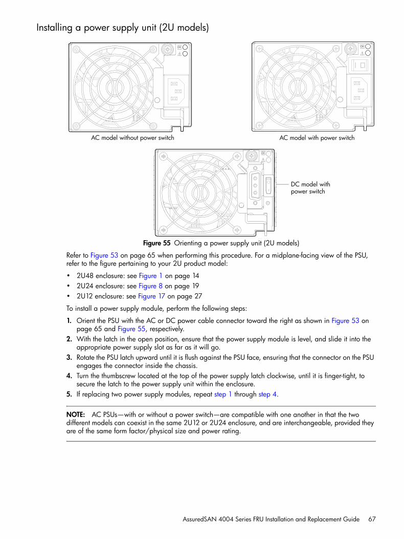
AssuredSAN 4004 Series FRU Installation and Replacement Guide 67
Installing a power supply unit (2U models)
Figure 55 Orienting a power supply unit (2U models)
Refer to Figure 53 on page 65 when performing this procedure. For a midplane-facing view of the PSU, refer to the figure pertaining to your 2U product model:
• 2U48 enclosure: see Figure 1 on page 14• 2U24 enclosure: see Figure 8 on page 19• 2U12 enclosure: see Figure 17 on page 27
To install a power supply module, perform the following steps:
1. Orient the PSU with the AC or DC power cable connector toward the right as shown in Figure 53 on page 65 and Figure 55, respectively.
2. With the latch in the open position, ensure that the power supply module is level, and slide it into the appropriate power supply slot as far as it will go.
3. Rotate the PSU latch upward until it is flush against the PSU face, ensuring that the connector on the PSU engages the connector inside the chassis.
4. Turn the thumbscrew located at the top of the power supply latch clockwise, until it is finger-tight, to secure the latch to the power supply unit within the enclosure.
5. If replacing two power supply modules, repeat step 1 through step 4.
NOTE: AC PSUs—with or without a power switch—are compatible with one another in that the two different models can coexist in the same 2U12 or 2U24 enclosure, and are interchangeable, provided they are of the same form factor/physical size and power rating.
AC model without power switch AC model with power switch
DC model with power switch
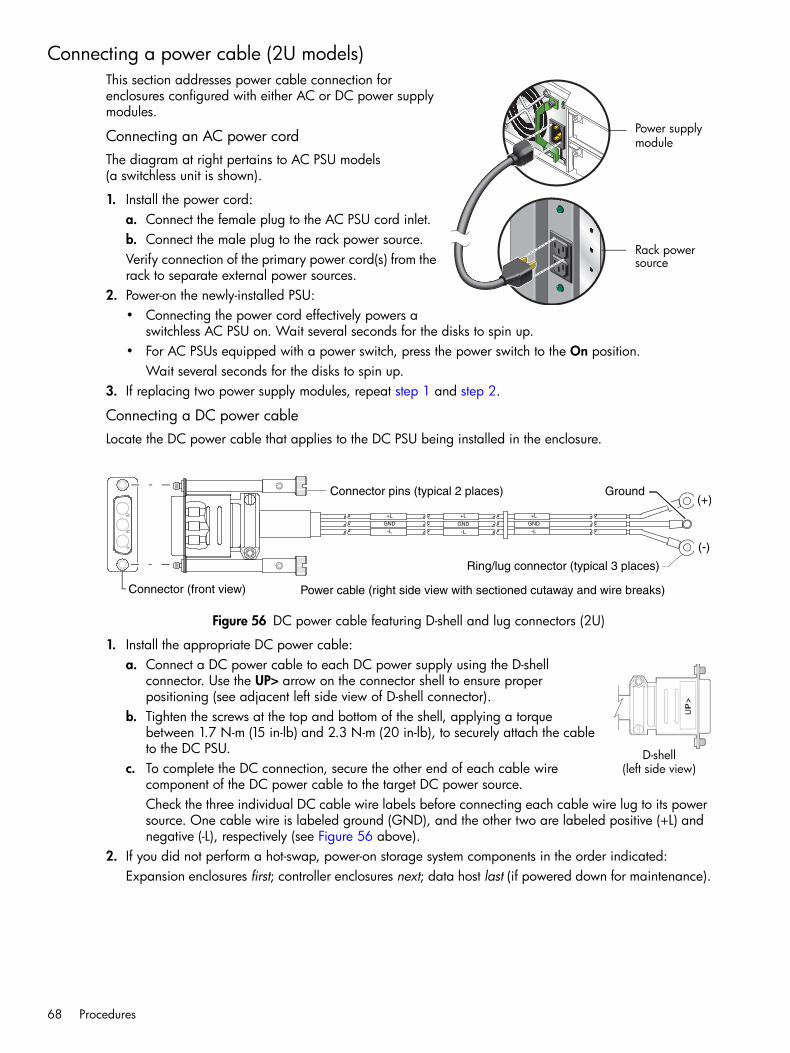
68 Procedures
Connecting a power cable (2U models)This section addresses power cable connection for enclosures configured with either AC or DC power supply modules.
Connecting an AC power cordThe diagram at right pertains to AC PSU models (a switchless unit is shown).
1. Install the power cord:a. Connect the female plug to the AC PSU cord inlet.b. Connect the male plug to the rack power source.Verify connection of the primary power cord(s) from the rack to separate external power sources.
2. Power-on the newly-installed PSU:• Connecting the power cord effectively powers a
switchless AC PSU on. Wait several seconds for the disks to spin up.• For AC PSUs equipped with a power switch, press the power switch to the On position.
Wait several seconds for the disks to spin up.3. If replacing two power supply modules, repeat step 1 and step 2.
Connecting a DC power cableLocate the DC power cable that applies to the DC PSU being installed in the enclosure.
Figure 56 DC power cable featuring D-shell and lug connectors (2U)
1. Install the appropriate DC power cable:a. Connect a DC power cable to each DC power supply using the D-shell
connector. Use the UP> arrow on the connector shell to ensure proper positioning (see adjacent left side view of D-shell connector).
b. Tighten the screws at the top and bottom of the shell, applying a torque between 1.7 N-m (15 in-lb) and 2.3 N-m (20 in-lb), to securely attach the cable to the DC PSU.
c. To complete the DC connection, secure the other end of each cable wire component of the DC power cable to the target DC power source. Check the three individual DC cable wire labels before connecting each cable wire lug to its power source. One cable wire is labeled ground (GND), and the other two are labeled positive (+L) and negative (-L), respectively (see Figure 56 above).
2. If you did not perform a hot-swap, power-on storage system components in the order indicated:Expansion enclosures first; controller enclosures next; data host last (if powered down for maintenance).
Power supplymodule
Rack powersource
Power cable (right side view with sectioned cutaway and wire breaks)
+L
GND
-L
+L
GND
-L
+L
GND
-L
Connector (front view)
Connector pins (typical 2 places)
Ring/lug connector (typical 3 places)
(+)
(-)
Ground
D-shell(left side view)

AssuredSAN 4004 Series FRU Installation and Replacement Guide 69
Verifying component operation (2U models)Examine PSU module status as indicated in the table below.
LEDs for a PSU are located in the top right corner of the module face, as shown in Figure 55 on page 67.
The top LED corresponds to LED number (1) above, and the bottom LED corresponds to number (2) above. If the Voltage/Fan Fault/Service Required LED is illuminated amber, the PSU module has not gone online, and likely failed its self-test. Remove and reinstall the PSU module. In addition to viewing the PSU LEDs, verify that the cooling fans are spinning. Also see Using management interfaces on page 88 as an alternative to physically observing LEDs to verify component operation.
Installing a power supply unit (4U models)
Figure 57 Orienting a power supply unit (4U models)
Refer to Figure 58 on page 70 when performing this procedure. For a midplane-facing view of the PSU, see Figure 12 on page 23.
To install a power supply module, perform the following steps:
1. Orient the PSU with the power cable connector on the bottom as shown above.2. With the handle in the open position, ensure that the power supply module is level, and slide it into the
appropriate power supply slot as far as it will go.3. Using your index finger, move the red button up, ensuring that the connector on the PSU engages the
connector inside the chassis.4. If replacing two power supply modules, repeat step 1 through step 3.
Table 10 Power supply unit LED descriptions (2U models)
LED No./Description Color State Definition
1 — Input Source Power Good Green On Power is on and input voltage is normal.
Off Power is off, or input voltage is below the minimum threshold.
2 — Voltage/Fan Fault/Service Required
Amber On Output voltage is out of range, or a fan is operating below the minimum required RPM.
Off Output voltage is normal.
Power supply switch (chassis-mounted)
AC power connect DC powerconnect
AC model DC model
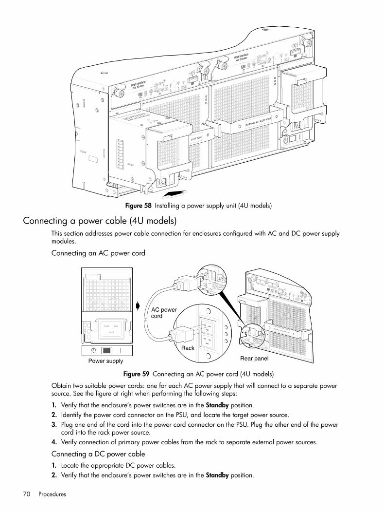
70 Procedures
Figure 58 Installing a power supply unit (4U models)
Connecting a power cable (4U models)This section addresses power cable connection for enclosures configured with AC and DC power supply modules.
Connecting an AC power cord
Figure 59 Connecting an AC power cord (4U models)
Obtain two suitable power cords: one for each AC power supply that will connect to a separate power source. See the figure at right when performing the following steps:
1. Verify that the enclosure’s power switches are in the Standby position.2. Identify the power cord connector on the PSU, and locate the target power source.3. Plug one end of the cord into the power cord connector on the PSU. Plug the other end of the power
cord into the rack power source.4. Verify connection of primary power cables from the rack to separate external power sources.
Connecting a DC power cable1. Locate the appropriate DC power cables.2. Verify that the enclosure’s power switches are in the Standby position.
CACHE
LINK
DIRTY
LINK
ACT
CLICLI
SERVICE−2
SERVICE−1
PORT 0 PORT 1
PORT 2 PORT 3
6Gb/s
Power supply Rear panel
Rack
WARNING: NOT A LIFT POINT
cordAC power

AssuredSAN 4004 Series FRU Installation and Replacement Guide 71
3. Connect the DC power cable to each DC power supply using the 2-circuit header connector.4. Tighten the screws at the base of the connector—left and right sides—applying a torque between 1.7
N-m (15 in-lb) and 2.3 N-m (20 in-lb), to securely attach the cable to the DC power supply module.5. To complete the DC connection, secure the other end of each cable wire component of the DC power
cable to the target DC power source (see Figure 52 on page 65).Check the two individual DC cable wire labels before connecting each cable wire lug to its power source. One wire is labeled positive (+L) and the other is labeled negative (-L). The 4004 Series enclosure is grounded independently of this DC cable. The chassis ground wire is connected from a dual lug on its mounting rail to the rack in which it is mounted.
CAUTION: Connecting to a DC power source outside the designated -48VDC nominal range (-36VDC to -72 VDC) may damage the enclosure.
Verifying component operation (4U models)Examine PSU module status as indicated in the table below.
LEDs for a PSU are located in the bottom left corner of the module face, as shown above.
If the Voltage/Fan Fault/Service Required LED is illuminated amber, the PSU module has not gone online, and likely failed its self-test. Remove and reinstall the PSU module. In addition to viewing the PSU LEDs, verify that the cooling fans are spinning. Also see Using management interfaces on page 88 as an alternative to physically observing LEDs to verify component operation.
Replacing a fan control moduleThis section provides procedures for replacing a failed fan control module (FCM). The FCM FRU is unique to 4U56 enclosures. Illustrations in fan control module replacement procedures show rear panel views of the enclosure, and FCMs are properly aligned for insertion into the rear panel of the enclosure.
123
Power supply switch (chassis-mounted)
123
AC power connect DC power
AC model DC model
connect
Table 11 Power supply unit LED descriptions (4U models)
LED No./Description Color State Definition
1 — AC Input Source Green On Power is on and input voltage is normal.
Off No AC input to PSU.
2 — Voltage/Fan Fault/Service Required
Amber OnBlinking
Output voltage is out of range, or a fan is operating below the minimum required RPM.
Off Fault not detected.
3 — DC Power Green On Main output power on.
Off Power is off; main output is off; or a fault is detected.

72 Procedures
A single FCM is sufficient to maintain operation of the enclosure. You need not halt operations and completely power-off the enclosure when replacing only one FCM; however, a complete orderly shutdown is required if replacing both fan control modules.
TIP: See Table 12 for additional information about fan module faults and recommended actions.
Before you begin
CAUTION: Removing a fan control module significantly disrupts the enclosure’s airflow. Do not remove the FCM until you have received the replacement module.
See the CAUTION bullets regarding “electrostatic discharge” and “anti-static protection” on page 30.
Verifying component failureYou can observe fan module component health (PSUs, fans) using LEDs, management interfaces, or a combination thereof to verify component failure or component operation (see Using management interfaces on page 88 for more information).
When either a fan or power supply component fails, the SMC or RAIDar provide notification; faults are recorded in the event log; and the FCM’s status LED color changes to amber to indicate a fault condition.
Table 12 describes menu navigation using the SMC (v3) or RAIDar (v2). The shorthand v3 and v2 prefixes are used to distinguish between the GUI product versions supported by 4004 Series enclosures.
Table 12 also references a CLI command. You can set a CLI preference to use v3 commands to manage virtual storage or to use v2 commands to manage linear storage. See the TIP bullets regarding CLI “default management mode” and “current management mode” page 35.
Table 12 Fan control module faults and recommended actions (4U56)
Problem Recommended action
Power supply fan warning or failure, or fan module warning or failureEvent code 552 or 558 (4U56)
• v3: Verify that all fans are working using the SMC.Click the System tab within the topics pane and from the System topic, select the Rear tab. Hover over each fan control module to view health attributes.You can also select the Table tab and view health status for fan control modules and other components in tabular form.
• v2: Verify that all fans are working using RAIDar.In the Configuration View, expand Physical, right-click the enclosure and select View > Overview. Select either Rear Graphical or Rear Tabular to view health attributes.
• Optionally, you can verify that all fans are working using the CLI.The show fans command will output health status for fans in the specified enclosure.
• Ensure that the power supply modules are properly seated and secured within their slots.
• Ensure that the fan control modules are properly seated and secured within their slots.
• Ensure that no slots are left open for more than two minutes. If you must replace the FRU, leave the old module in place until the replacement arrives, to maintain optimal airflow and avoid overheating.
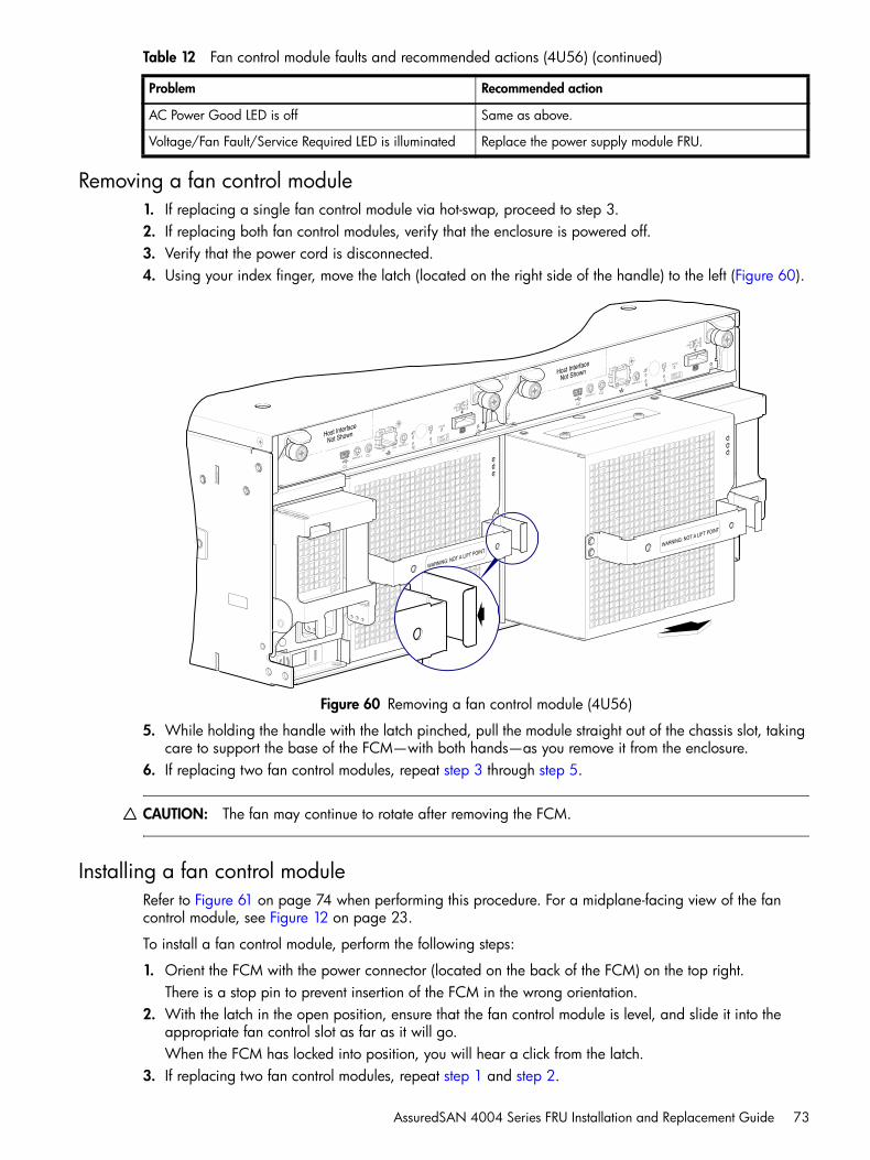
AssuredSAN 4004 Series FRU Installation and Replacement Guide 73
Removing a fan control module1. If replacing a single fan control module via hot-swap, proceed to step 3.2. If replacing both fan control modules, verify that the enclosure is powered off.3. Verify that the power cord is disconnected.4. Using your index finger, move the latch (located on the right side of the handle) to the left (Figure 60).
Figure 60 Removing a fan control module (4U56)
5. While holding the handle with the latch pinched, pull the module straight out of the chassis slot, taking care to support the base of the FCM—with both hands—as you remove it from the enclosure.
6. If replacing two fan control modules, repeat step 3 through step 5.
CAUTION: The fan may continue to rotate after removing the FCM.
Installing a fan control moduleRefer to Figure 61 on page 74 when performing this procedure. For a midplane-facing view of the fan control module, see Figure 12 on page 23.
To install a fan control module, perform the following steps:
1. Orient the FCM with the power connector (located on the back of the FCM) on the top right. There is a stop pin to prevent insertion of the FCM in the wrong orientation.
2. With the latch in the open position, ensure that the fan control module is level, and slide it into the appropriate fan control slot as far as it will go. When the FCM has locked into position, you will hear a click from the latch.
3. If replacing two fan control modules, repeat step 1 and step 2.
AC Power Good LED is off Same as above.
Voltage/Fan Fault/Service Required LED is illuminated Replace the power supply module FRU.
Table 12 Fan control module faults and recommended actions (4U56) (continued)
Problem Recommended action
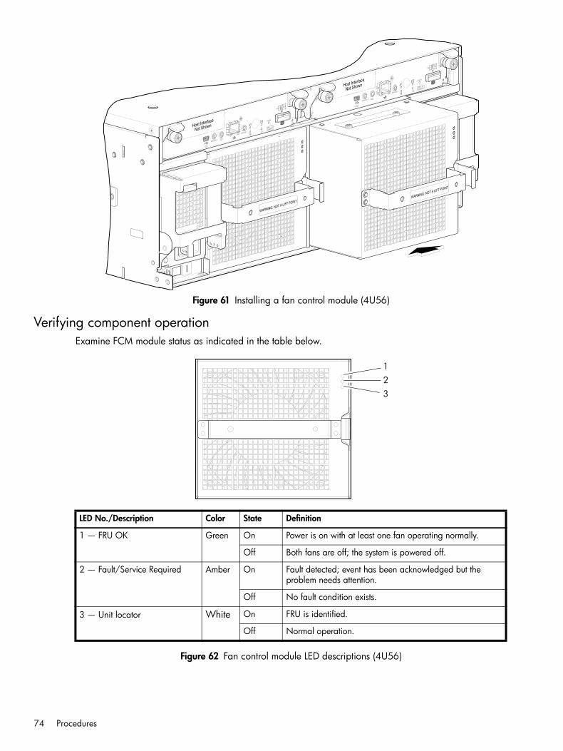
74 Procedures
Figure 61 Installing a fan control module (4U56)
Verifying component operationExamine FCM module status as indicated in the table below.
Figure 62 Fan control module LED descriptions (4U56)
LED No./Description Color State Definition
1 — FRU OK Green On Power is on with at least one fan operating normally.
Off Both fans are off; the system is powered off.
2 — Fault/Service Required Amber On Fault detected; event has been acknowledged but the problem needs attention.
Off No fault condition exists.
3 — Unit locator White On FRU is identified.
Off Normal operation.
123

AssuredSAN 4004 Series FRU Installation and Replacement Guide 75
Replacing ear componentsBefore you begin
CAUTION: Verify that you have the proper FRU kit (left or right) for the ear components being replaced.
See CAUTION bullets regarding “electrostatic discharge” and “anti-static protection” on page 30.
Enclosure ear kit FRUs are available for the left and right ears of the chassis front panel. The following replacement procedure applies to ear kits provided with the 4004 Series enclosure models. Refer to the following illustrations pertaining to your product ear kit. Illustrations in ear kit replacement procedures show front panel views of each enclosure, and ear bezel components are properly aligned for attachment to the ears on the front panel of the enclosure.
2U24 chassis earsFigure 63 shows the left ear flange of a 2U24 model with the LED circuit board installed. The enclosure bezel is removed to reveal the left ear and SFF disks. See Attaching and removing the enclosure bezel on page 32 (Figure 21) for bezel attachment and removal details.
Figure 63 Replacing left ear components (2U24)
Figure 64 shows the right ear flange of a 2U24 model. The enclosure bezel is removed to reveal the right ear. The example uses an empty 2U24 chassis. The LED circuit board is shown exploded from its installed position, and aligned with the light pipe sub-assembly, which is integral to the enclosure bezel.
Figure 64 Replacing right ear components (2U24)
Left ear with bezel removed(disk drives shown)
OK
Right ear explosion(empty chassis shown)
Unit LocatorFault/Service RequiredFRU OKTemperature Fault
LED circuitboard
LED light pipessub-assembly(included in bezel)

76 Procedures
The enclosure bezel attaches to four ball studs on the front of the enclosure: each 2U24 ear flange hosts two ball studs. Relative to both left and right ear kits for 2U24 models, see Removing ear components on page 79 and Installing ear kit components on page 79.
2U12 chassis earsFigure 65 shows the left ear flange of a 2U12 model with the LED circuit board exploded from its installed position. The enclosure bezel is removed to reveal the left ear and LFF disks. See Attaching and removing the enclosure bezel on page 32 (Figure 21) for bezel attachment and removal details.
Figure 65 Replacing left ear components (2U12)
Figure 66 shows the right ear flange of a 2U12 model. The enclosure bezel is removed to reveal the right ear and LFF disks. The LED circuit board is shown exploded from its installed position, and aligned with the light pipes, which are integral to the enclosure bezel. Individual light pipes are shown exploded from the front of the enclosure bezel.
Figure 66 Replacing right ear components (2U12)
The enclosure bezel attaches to four ball studs on the front of the enclosure: each 2U12 ear flange hosts two ball studs. Relative to both left and right ear kits for 2U12 models, see Removing ear components and Installing ear kit components on page 79.
Left ear with bezel removed
OK
Right ear explosion
Unit LocatorFault/Service RequiredFRU OKTemperature Fault
LED circuit board

AssuredSAN 4004 Series FRU Installation and Replacement Guide 77
2U48 chassis earsFigure 67 shows the left ear of a 2U48 model with the LED circuit board exploded from its installed position on the ear flange. The enclosure bezel is removed to reveal the left ear flange and the left drawer in closed position. See Attaching and removing the enclosure bezel on page 32 (Figure 21) for bezel attachment and removal details.
Figure 67 Replacing left ear components (2U48)
Figure 68 shows the right ear of a 2U48 model. The enclosure bezel is removed to reveal the right ear flange and the right drawer in closed position. The LED circuit board is shown exploded from its installed position—and aligned with the light pipe sub-assembly—which is integral to the enclosure bezel.
Figure 68 Replacing right ear components (2U48)
The enclosure bezel attaches to four ball studs on the front of the enclosure: each 2U48 chassis ear flange hosts two ball studs. Relative to both left and right ear kits, see Removing ear components and Installing ear kit components.
Left ear with bezel removed(left drawer shown)
OK
Right ear explosion(right drawer shown)
Unit LocatorFault/Service RequiredFRU OKTemperature Fault
LED circuitboard
LED light pipes subassembly(included in bezel)

78 Procedures
4U56 chassis earsFigure 69 shows the left ear of a 4U56 model with the LED circuit board exploded from its installed position on the ear flange. The enclosure bezel is removed to reveal the left ear flange and the left drawer in closed position. See Attaching and removing the enclosure bezel on page 32 (Figure 22) for bezel attachment and removal details.
Figure 69 Replacing left ear components (4U56)
Figure 70 shows the right ear of a 4U56 model. The enclosure bezel is removed to reveal the right ear flange and the right drawer in closed position. The LED circuit board is shown exploded from its installed position—and aligned with the light pipe sub-assembly—which is integral to the enclosure bezel.
Figure 70 Replacing right ear components (4U56)
The enclosure bezel attaches to two ball studs on the front of the enclosure: each 4U56 chassis ear flange hosts one ball stud. Relative to both left and right ear kits, see Removing ear components and Installing ear kit components on page 79.
TIP: If your 4U56 enclosure is equipped with a bezel that employs an optional air filter, refer to the Enclosure Bezel Kit Installation document—included in your product shipkit—for instructions on servicing the air filter.
AssuredSAN
Left ear with bezel removed
OK
Right ear explosion
Unit LocatorFault/Service Required
FRU OKTemperature Fault
LED light pipes subassembly(included in bezel)

AssuredSAN 4004 Series FRU Installation and Replacement Guide 79
Removing ear componentsSee the appropriate ear illustrations for your product model when removing the bezel and ear components:
• 2U12 chassis: see Figure 65 (left ear) and Figure 66 on page 76 (right ear)• 2U24 chassis: see Figure 63 (left ear) and Figure 64 on page 75 (right ear)• 2U48 chassis: see Figure 67 (left ear) and Figure 68 on page 77 (right ear)• 4U56 chassis: see Figure 69 (left ear) and Figure 70 on page 78 (right ear)
1. Stop all I/O from hosts to the system.2. Use management software to shut down any other components necessary.3. Power off the enclosure. Take care to remove both power cords.4. Remove the enclosure bezel:
• See Figure 21 on page 32 and supporting narrative for 2U enclosure bezel removal.• See Figure 22 on page 33 and supporting narrative for 4U enclosure bezel removal.
5. On the target ear, loosen the two screws securing the LED circuit board to the threaded mounting sleeves. Use a No.2 Phillips screw driver.
NOTE: With the exception of the right ear on the 2U24 chassis, the mounting sleeves protrude forward from the ear flange. On 2U24 chassis, an angle bracket is affixed to the front of the right ear, with mounting sleeves protruding rightward from the base of the angle bracket.
Remove the screws and retain them for use when installing the new LED circuit board.6. Remove the ESD cage protecting the LED circuit board, and retain it for reinstallation:
• This step applies to left ear kit replacement only: see Figure 63 on page 75 for 2U24 enclosures.• This step applies to left ear kit replacement only: see Figure 65 on page 76 for 2U12 enclosures.• This step applies to left ear kit replacement only: see Figure 67 on page 77 for 2U48 enclosures.• This step applies to left ear kit replacement only: see Figure 69 on page 78 for 4U56 enclosures.
7. Disconnect the flexible ribbon cable from the back of the LED circuit board.a. Pull gently on the LED circuit board to stretch the ribbon cable attached to the back of the board.b. Reach behind the LED circuit board, and slightly pull outward on the locking mechanism of the
connector to release the flexible ribbon cable from the circuit board.8. Remove the LED circuit board.• 2U12 chassis circuit boards and LEDs: see Figure 65 (left ear) and Figure 66 on page 76 (right ear)• 2U24 chassis circuit boards and LEDs: see Figure 63 (left ear) and Figure 64 on page 75 (right ear)• 2U48 chassis circuit boards and LEDs: see Figure 67 (left ear) and Figure 68 on page 77 (right ear)• 4U56 chassis circuit boards and LEDs: see Figure 69 (left ear) and Figure 70 on page 78 (right ear)
Installing ear kit componentsSee the appropriate ear illustrations for your product model when installing ear components:
• 2U12 chassis: see Figure 65 (left ear) and Figure 66 on page 76 (right ear)• 2U24 chassis: see Figure 63 (left ear) and Figure 64 on page 75 (right ear)• 2U48 chassis: see Figure 67 (left ear) and Figure 68 on page 77 (right ear)• 4U56 chassis: see Figure 69 (left ear) and Figure 70 on page 78 (right ear)
1. Locate the replacement LED circuit board for the target ear.2. Verify that the enclosure is powered off.3. Install the LED circuit board for each target ear:
a. Properly orient the replacement LED circuit board, and align it for installation onto the ear flange as shown in the pertinent illustration (see bullet list above).

80 Procedures
NOTE: With the exception of the right ear on the 2U24 chassis, the mounting sleeves protrude forward from the ear flange. On 2U24 chassis, an angle bracket is affixed to the front of the right ear, with mounting sleeves protruding rightward from the base of the angle bracket.
b. Release the locking mechanism on the ribbon cable connector located on the back of the LED circuit board.
c. While holding the flexible ribbon cable steady, insert it into the connector on the back of the LED circuit board, and push in on the locking mechanism to secure the cable connection.
d. Locate the ESD cage and align its through-holes with those on the LED circuit board:• This step applies to left ears only: see Figure 63 on page 75 for 2U24 enclosures.• This step applies to left ears only: see Figure 65 on page 76 for 2U12 enclosures.• This step applies to left ears only: see Figure 67 on page 77 for 2U48 enclosures.• This step applies to left ears only: see Figure 69 on page 78 for 4U56 enclosures.
e. Locate the LED circuit board fastener screws that you previously removed, and insert a screw through each of the board’s two mounting holes, and into the threaded hole of the sleeve.
f. Take care to ensure that the screw threads correctly mesh with the threads in the hole—in order to avoid cross-threading or stripping—and hand tighten them. If a calibrated torque driver is available, torque each screw to 3 in./lbs.
g. Verify that the LED circuit board is securely installed, and the flexible ribbon cable is fully-seated into the connector, and locked in place.
4. Gently slip the enclosure bezel cover onto the push-fit mounting ball studs, taking care to guide the LED indicators through the bezel’s ear covers.
5. Power on the enclosure.
TIP: See the AssuredSAN 4004 Series Setup Guide for descriptions of front panel LEDs.
Verifying component operationEnclosure status LEDs are located on the front of the controller enclosure. During normal operation, the FRU OK and Temperature Fault LEDs are green, and the other status LEDs located on the right ear are off.
Transceivers used in CNC portsAssuredSAN 4824/4834 models use Converged Network Controller (CNC) technology, allowing you to select the desired host interface protocol from available Fibre Channel (FC) or Internet SCSI (iSCSI) host interface protocols supported by the system. You can use the CLI to set all controller module CNC ports to use one of these host interface protocols: 16 Gbit/s FC; 8 Gbit/s FC; 10GbE iSCSI; or 1 Gbit/s iSCSI.
Alternatively, you can use the CLI to set CNC ports to support a combination of host interface protocols. When configuring a combination of host interface protocols, host ports 0 and 1 must be set to FC (either both 16 Gbit/s or both 8 Gbit/s), and host ports 2 and 3 must be set to iSCSI (either both 10GbE or both 1 Gbit/s), provided the CNC ports use the qualified SFP connectors and cables required for supporting the selected host interface protocol. CNC ports can be used for host connection or replication, provided the optional AssuredRemote™ feature is licensed.
IMPORTANT: To change the host port mode for CNC ports, follow the “Change the host port mode” instructions provided in the AssuredSAN 4004 Series Setup Guide.

AssuredSAN 4004 Series FRU Installation and Replacement Guide 81
Replacing a Fibre Channel transceiverThis section provides steps for replacing a small form-factor pluggable (SFP transceiver) connector used in a Fibre Channel controller module host port. An example SFP connector is shown below. It is pictorially oriented to align for insertion into the CNC port, such that the connector is flush with the IOM face plate on the enclosure rear panel.
Figure 71 Sample SFP connector
NOTE: See the controller module — rear panel components topic within the Setup Guide for illustrations showing FC SFPs installed within the IOM.
Before you begin
CAUTION: Mishandling fibre-optic cables can degrade performance. Do not twist, fold, pinch, or step on fibre-optic cables. Do not bend them tighter than a 2-inch radius.
See CAUTION bullets regarding “electrostatic discharge” and “anti-static protection” on page 30.
CAUTION: To prevent potential loss of access to data, be sure to identify the correct cable and SFP connector for subsequent removal.
Verifying component failureTransceivers are part of a data path that includes multiple components, such as the transceiver, a cable, another SFP, and an HBA (host bus adapter). A reported fault can be caused by any component in the data path. To identify the location of the fault, check the Link Status/Link Activity LED on the controller module face plate, and check the link status and link activity LEDs on the server. Also, check the cable for kinks, crimping or other possible damage.
TIP: See the AssuredSAN 4004 Series Setup Guide for descriptions of rear panel LEDs.
Removing an SFP modulePerform the following procedure to remove an SFP connector. When removing an FC SFP that has previously limited the port speed—and replacing it with a higher-rated SFP—it is possible, though rare, that auto-negotiation will not enable the higher port speed. Rebooting the array or the host resolves the problem.
1. Disconnect the fibre-optic interface cable by squeezing the end of the cable connector.If the SFP does not have a cable, it should have a plug (retained from installation).

82 Procedures
Figure 72 Disconnect fibre-optic interface cable from SFP
2. SFPs are commonly held in place by a small wire bail actuator. Flip the actuator up.
Figure 73 Flip SFP actuator upwards
3. Grasp the SFP between your thumb and index finger, and carefully remove it from the controller module.
Installing an SFP modulePerform the following procedure to install an SFP connector.
1. Locate the SFPs that will be used in the CNC ports.• If the SFP has a plug, remove it before sliding the connector into the CNC port. Retain the plug.• If using different SFPs in combination, locate the appropriate SFP pertaining to each target CNC
port, and note the port number (0 — 3) into which each SFP will install.• See the “Changing host-interface settings” topic in the Storage Management Guide for information
about configuring CNC ports for use with qualified FC or iSCSI SFP options. Also see the show ports and set host-port-mode CLI commands within the CLI Reference Guide.
2. Install the SFP and connect the host interface cable per Figure 74 below:a. Flip the SFP actuator and revolve it downwards.b. Insert the SFP into the CNC port and ensure that it locks securely into place.c. Align the fibre-optic interface cable with the duplex jack at the end of installed SFP.
Figure 74 Install the SFP into the CNC port
3. Connect the fibre-optic interface cable to the duplex jack at the end of the SFP connector.4. Repeat step 1 through step 3 for each SFP requiring installation into a CNC port.
Fibre-optic cable attached to SFP
Fibre-optic cable disconnected
Flip actuator/revolve upward
PORT 1
PORT 1
PORT 1
2a 2b
2c
3
Target CNC port on controller module face plate

AssuredSAN 4004 Series FRU Installation and Replacement Guide 83
Verifying component operationView the Link Status/Link Activity LED on the controller module face plate. A blinking LED indicates that no link is detected. Also check the link status and link activity LEDs on the host.
Replacing a 10GbE SFP+ transceiverThis section provides steps for removing and replacing a small form-factor pluggable plus (SFP+ transceiver) connector used in an Internet SCSI (iSCSI) controller host port. SFP+ connectors are similar in appearance to SFP connectors. These transceivers enable 10GbE equipment designs with high port density, based on electrical and mechanical enhancements to SFP specifications developed by the Small Form Factor (SFF) Committee.Removing and replacing an SFP+ consists of the same basic steps described for removing and replacing an SFP in the preceding section. This procedure refers to the preceding Replacing a Fibre Channel transceiver instructions. When reviewing the procedure as it pertains to the 10Gb iSCSI host ports, note that your particular cables may be either copper or fibre-optic for the SFP+, depending upon how your system was initially configured, and the SFP+ option used.
NOTE: See the controller module — rear panel components topic within the Setup Guide for illustrations showing 10GbE SFP+ connectors installed within the IOM.
Replacing a 1Gb RJ-45 SFP transceiverThis section provides steps for removing and replacing a small form-factor pluggable transceiver connector used in an Internet SCSI (iSCSI) controller host port. The copper RJ-45 connectors are similar in appearance to other SFP connectors. Removing and replacing an RJ-45 SFP consists of the same basic steps described for removing and replacing an SFP in the preceding FC and 10GbE iSCSI sections. This procedure refers to Replacing a Fibre Channel transceiver. When reviewing the procedure as it pertains to the 1 Gb iSCSI host ports, note that this particular SFP does not support an optic option for 1 Gb.
NOTE: See the controller module — rear panel components” topic within the Setup Guide for an illustration showing an 1 Gb RJ-45 SFP installed within the IOM.
Table 13 Removing and replacing a 10GbE SFP+ transceiver
To accomplish this sequential process See the following procedures
1. Remove SFP+ connector. a. Before you begin on page 81.b. Verifying component failure on page 81.c. Removing an SFP module on page 81.
2. Install the replacement SFP+ connector. Installing an SFP module on page 82.
3. Verify proper operation for the removed and reinstalled component.
Verifying component operation on page 83.
Table 14 Removing and replacing a 1 Gb SFP transceiver
To accomplish this sequential process See the following procedures
1. Remove SFP connector. a. Before you begin on page 81.b. Verifying component failure on page 81.c. Removing an SFP module on page 81.
2. Install the replacement SFP connector. Installing an SFP module on page 82.
3. Verify proper operation for the removed and reinstalled component.
Verifying component operation on page 83.

84 Procedures
Replacing a storage enclosure chassisThe controller enclosure or expansion enclosure chassis replacement procedure replaces a damaged chassis FRU, which consists of the structural support metal, the exterior sheet metal housing, and the assembled/installed midplane. The procedure includes removing all FRU components from a damaged chassis and installing them into a replacement chassis.
IMPORTANT: AssuredSAN 4004 Series storage enclosures (2U12/2U24/2U48/4U56) are described in the FRUs chapter and in the Setup Guide.
Regardless of specific product model, a fully functional replacement chassis requires the successful removal and installation of the following components:
• Enclosure bezel (covers enclosure front panel)• All disk drive modules• Ear components• Two power supply units of the same compatible model type (both AC or both DC)
The 4U56 also uses FCM components.• One or two I/O modules (of the same model type)
CNC models require the successful removal and installation of qualified SFP options. This procedure makes extensive use of the FRU component procedures described elsewhere in Chapter 2.
Before you begin
CAUTION: Do not remove the enclosure until you have received the replacement enclosure.
See CAUTION bullets regarding “electrostatic discharge” and “anti-static protection” on page 30.
1. Schedule down time that will allow for shutdown; sixty minutes of replacement work; and restart.2. Verify the existence of a known/good backup of the system.3. Record system settings for future use and label all cables.4. Prepare a suitable static-protected work environment to accommodate chassis replacement.
Verifying component failureThe controller enclosure FRU includes the enclosure’s metal housing and the midplane that connects I/O modules, disk drive modules, and power supply modules. This FRU replaces an enclosure that has been damaged, or whose midplane has been damaged. Often, a damaged midplane will appear as though an I/O module has failed. If you replace an IOM, and it does not remedy the fault, you may need to replace the enclosure.
You can observe enclosure health (front panel and rear panel) using management interfaces to verify enclosure/component failure or enclosure/component operation (see Using management interfaces on page 88 for more information).
Preparing to remove a damaged storage enclosure chassisBecause you are removing and replacing an entire storage enclosure, neither the hot-swap capability that applies to replacing individual redundant FRUs in an operational storage enclosure, nor the hot-add of a drive enclosure to an operational storage system, apply to this procedure.
1. Stop all I/O from hosts to the system. See Stopping I/O on page 36.2. Shut down the controllers. See Shutting down a controller module on page 37.3. Power off the system (controller enclosure first; expansion enclosures next). See Power supply units on
page 61, and refer to the power cycling procedures for your particular power supply model.

AssuredSAN 4004 Series FRU Installation and Replacement Guide 85
Table 15 Removing and replacing a storage enclosure chassis and its FRUs
To accomplish this sequential process See the following procedures
1. Remove the enclosure bezel to provide access to front panel components.
a. Removing the enclosure bezel (2U) on page 33, orb. Removing the enclosure bezel (4U) on page 33.
2. Remove disk modules from the damaged chassis.1(2U12/2U24 chassis: upon completion, proceed to step 5)
a. Before you begin on page 51.b. Removing a disk drive module (2U12/2U24) on
page 52.
3. Remove disk modules from the damaged chassis.1(2U48 chassis: upon completion, proceed to step 5)
a. Before you begin on page 51.b. Accessing a 2U16 drawer on page 44.c. Removing a disk drive module (2U48) on page 53.
4. Remove disk modules from the damaged chassis.1(4U56 chassis: upon completion, proceed to step 5)
a. Before you begin on page 51.b. Accessing a 4U28 drawer on page 46.c. Removing a disk drive module (4U56) on page 54.
5. Remove the ear components from the damaged (2U12/2U24/2U48/4U56) chassis.
a. Before you begin on page 75.b. Removing ear components on page 79.
6. Remove power and data cables. Removing a damaged storage enclosure chassis from the rack on page 86 (step 1).
7. Remove the damaged storage enclosure chassis from the rack.
Removing a damaged storage enclosure chassis from the rack on page 86.
8. Remove the power supply units from the damaged chassis, and install them in the replacement chassis.
a. Before you begin on page 60.b. Power supply units on page 61.c. Removing a power supply unit (2U models) on page 65.d. Removing a power supply unit (4U models) on page 66.e. Installing a power supply unit (2U models) on page 67.f. Installing a power supply unit (4U models) on page 69.
9. Remove the fan control modules from the damaged chassis, and install them in the replacement chassis (4U56 chassis only).
a. Before you begin on page 72.b. Removing a fan control module on page 73.c. Installing a fan control module on page 73.
10.Remove each IOM from the damaged chassis, and install it in the replacement chassis.2
a. Before you begin on page 34.b. Removing a controller module or expansion module on
page 38.c. Installing a controller module or expansion module on
page 41.
11.Remove each FC SFP from the damaged chassis, and install it in the replacement chassis (Fibre Channel models only).3
a. Before you begin on page 81.b. Removing an SFP module on page 81.c. Installing an SFP module on page 82.
12.Remove each 10GbE SFP from the damaged chassis, and install it in the replacement chassis (10GbE iSCSI models only).3
Replacing a 10GbE SFP+ transceiver on page 83. Also see Steps 10a — 10c immediately above.
13.Remove each 1 Gb SFP from the damaged chassis, and install it in the replacement chassis(1 Gb iSCSI models only).3
Replacing a 1Gb RJ-45 SFP transceiver on page 83.Also see Steps 10a — 10c above.
14. Install ear kit components on the replacement chassis ear.
Installing ear kit components on page 79.
15. Install the replacement storage enclosure chassis in the rack.
Installing the replacement storage enclosure in the rack on page 86.

86 Procedures
1Within the replacement enclosure, reinstall each disk drive or disk drive blank into the same disk slot from which it was removed from the damaged enclosure.
2Within the replacement enclosure, the IOM(s) and IOM blank—if applicable—must be reinstalled into the same IOM slots from which they were extracted from the damaged enclosure.
3If your enclosure model does not use CNC ports, ignore this step.
Removing a damaged storage enclosure chassis from the rackThis section provides a procedure for removing a damaged storage enclosure chassis from its rack location.
CAUTION: It is recommended that all disk drive modules be removed before removing the enclosure. Two people are required to move the enclosure.
1. Disconnect the power cables and data cables between devices as needed:a. Between the cascaded enclosures.b. Between the controller and peripheral SAN devices.c. Between the controller and the host.
2. Make sure the ear components are removed. See Removing ear components on page 79.3. Remove the retaining screws that secure the front and rear of the enclosure chassis to the rack and rails.4. Maintaining a level position, carefully slide the enclosure chassis from the rack.5. Place the chassis on a work surface near the replacement enclosure chassis, the removed disk drive
modules, ear components, and screws.6. Remove the side bracket from each side of the damaged enclosure chassis, and retain these rackmount
items with the other components for future use.
Installing the replacement storage enclosure in the rackThis section provides a procedure for installing the replacement enclosure in its rack location.
CAUTION: It is recommended that all disk drive modules be removed before lifting the enclosure. Two people are required to move the enclosure.
16. Install disk drive modules in the replacement chassis.1(2U48 and 4U56 chassis use drawers for disks)
a. FDE considerations on page 48b. Installing a disk drive module (2U12/2U24) on
page 55.c. Installing a disk drive module (2U48) on page 56.d. Installing a disk drive module (4U56) on page 57.
17. Complete the installation process. a. Connecting a power cable (2U models) on page 68.b. Connecting a power cable (4U models) on page 70c. Completing the process on page 87.
18.Verify proper operation for all removed and installed FRU components.
a. Disks—Verifying component operation on page 60.b. IOMs—Verifying component operation on page 42.c. PSUs—Verifying component operation (2U models) on
page 69.d. FCMs—Verifying component operation on page 74e. SFPs (if applicable)—Verifying component operation
on page 83.f. Verify PFU enabled (if applicable)—Configuring
partner firmware update on page 35.
Table 15 Removing and replacing a storage enclosure chassis and its FRUs (continued)
To accomplish this sequential process See the following procedures

AssuredSAN 4004 Series FRU Installation and Replacement Guide 87
NOTE: Refer to the Rackmount Bracket Kit Installation for your product for the procedure and mounting hardware.
1. Attach side brackets (standard rackmount installation) or main brackets (2-post rackmount installation) on the replacement enclosure chassis.
2. Support the bottom of the enclosure chassis. Carefully lift/align the chassis and while maintaining a level position for the enclosure, slide it into the rack.
3. Using the appropriate mounting hardware, secure the enclosure chassis to the rack.4. Install the ear components. See Installing ear kit components on page 79.5. Using the applicable retaining screws, secure the front and rear or the enclosure chassis to the rack and
rails.6. Attach the enclosure bezel to the front panel of the enclosure:
• For 2U enclosures, see Attaching the enclosure bezel (2U) on page 33.• For 4U enclosures, see Attaching the enclosure bezel (4U) on page 33.
Completing the processThis section provides a procedure for ensuring that the FRU components installed in the replacement controller enclosure chassis function properly.
1. Reconnect data cables between devices, as needed, to return to the original cabling configuration:• Between cascaded enclosures.• Between the controller and peripheral or SAN devices.• Between the controller enclosure and the host.
2. Reconnect power cables to the controller enclosure:• See Connecting a power cable (2U models) on page 68, or• See Connecting a power cable (4U models) on page 70.
3. Turn on the power switch to each power supply module if they are equipped with power switches.
NOTE: For powering-on AC PSUs with or without a power switch, and DC and AC PSUs with a power switch, see Power supply units on page 61.
Verifying component operation1. Restart system devices in the following sequence. Allow time for each device to complete its Power On
Self Tests (POST) before proceeding:a. Expansion enclosure(s)b. Controller enclosurec. Host (if powered down for maintenance)
2. Perform a rescan to force a fresh discovery of all expansion enclosures connected to the controller enclosure. This step clears the internal SAS layout information, reassigns enclosure IDs, and ensures the enclosures are displayed in the proper order. Use the CLI, the SMC, or RAIDar to perform the rescan:To perform a rescan using the CLI, enter the following command:
rescan
You can set a CLI preference to use v3 commands to manage virtual storage or to use v2 commands to manage linear storage. See TIP bullets regarding CLI “default management mode” and “current management mode” page 35.To rescan using the SMC (v3):a. Verify that both controllers are operating normally.b. Do one of the following:

88 Procedures
• Point to the System tab and select Rescan Disk Channels.• In the System topic, select Action > Rescan Disk Channels.
c. Click Rescan.To rescan using RAIDar (v2):a. Verify that both controllers are operating normally.b. In the Configuration View panel, right-click the system and select Tools > Rescan Disk Channels.c. Click Rescan.See “Correcting enclosure IDs” in the Setup Guide for additional information.
Using LEDsView LEDs on the front and rear of the enclosure (see “LED descriptions” within the AssuredSAN 4004 Series Setup Guide for more information).
Verify front panel LEDs:
• Verify that the Enclosure ID LED (located on the left ear) is illuminated green.• Verify that the FRU OK and Temperature Fault LEDs are illuminated green, and that the Fault/Service
Required LED is off (all three LEDs are located on the right ear).• For LFF disks, verify that the Power/Activity LED (bottom LED on front of disk) is illuminated green or
blinking green.Remove the enclosure bezel to view disk LEDs. Attach the bezel when finished viewing disk LEDs.
• For SFF disks, verify that the Power/Activity LED (left LED on front of disk) is illuminated green or blinking green.Remove the enclosure bezel to view disk LEDs. Attach the bezel when finished viewing disk LEDs.
Verify rear panel LEDs:
• Verify that each power supply module’s Input Source Power Good LED (top LED on PSU) is illuminated green.
• Verify that the FRU OK LED on each IOM face plate is illuminated green, indicating that the module has completed initializing, and is online.
Using management interfacesIn addition to viewing LEDs as described above, you can use management interfaces to monitor the health status of the system and its components, provided you have configured and provisioned the system, and enabled event notification (see “Getting Started” within the AssuredSAN Storage Management Guide for more information).
Select from the following methods to verify component operation:
• Use the SMC (v3) or RAIDar (v2) to check the health icons/values of the system and its components to either ensure that everything is okay, or to drill down to a problem component. The SMC and RAIDar use health icons to show OK, Degraded, Fault, or Unknown status for the system and its components. If you discover a problem component, follow the actions in its Health Recommendations field to resolve the problem.
• As an alternative to using the SMC or RAIDar, you can run the show system command in the CLI to view the health of the system and its components. If any component has a problem, the system health will be Degraded, Fault, or Unknown. If you discover a problem component, follow the actions in its Health Recommendations field to resolve the problem.
• Monitor event notification — With event notification configured and enabled, you can view event logs to monitor the health of the system and its components. If a message tells you to check whether an event has been logged, or to view information about an event in the log, you can do so using the SMC, RAIDar, or the CLI. Using either the SMC or RAIDar, you would view the event log and then hover over the event message to see detail about that event. Using the CLI, you would run the show events detail command (with additional parameters to filter the output) to see the detail for an event (see “Alphabetical list of commands > show events” within the AssuredSAN CLI Reference Guide for more information about command syntax and parameters).

AssuredSAN 4004 Series FRU Installation and Replacement Guide 89
A Drawer description for 2U48 chassisThis appendix provides reference information complementing the information provided in the FRUs chapter and in the procedure entitled Accessing a 2U16 drawer on page 44.
Drawer configurationTo gain access to the 2U48 enclosure drawers, you must first remove the enclosure bezel as described in Attaching and removing the enclosure bezel on page 32. To see the contents of a drawer, flip the handle upwards, and pull the drawer outward from the enclosure drawer bay as described in Opening and closing a 2U16 drawer on page 44.
Drawer pictorials are provided for the two enclosure drawer types in Figure 75. Drawer 0 and Drawer 1 use the same sub-assembly. Each drawer contains four disk bays, and each disk bay can accommodate four disks.
Figure 75 Enclosure front face pictorial featuring drawers (2U48)
Diagrams of the three drawer front panels with corresponding revolved side views showing disk slot numbering are provided in Figure 76. Drawers 0 and 1 provide access to disk bays on the right side of the drawer, whereas Drawer 2 provides access to disk bays on the left side of the drawer.
Figure 76 Schematic representation of drawers (2U48)
Loading requirementsSee Installing a disk drive module (2U48) on page 56 for instructions about installing a sledded-disk into a slot within a bay in the enclosure drawer. See Air management solution insert on page 49 for instructions
0 1 2
Drawer 2Drawer 1
Note: The enclosure bezel is removed to reveal the front panel; the bezel must be attached during operation.
Drawer ProfilesDisk bays with sequentially−numbered disk slots
Right side view(Revolved Y −90°)
Left side view(Revolved Y +90°)
47464544
43424140
39383736
35343332
31302928
27262524
23222120
19181716
0
1
15141312
111098
7654
3210
Right side view(Revolved Y −90°)
2
Note: Drawer 0 and 1 show right side views for disk bays and slots; whereas Drawer 2 shows a left side view.
Drawer 0

90 Drawer description for 2U48 chassis
about removing or installing an AMS into a disk bay in the enclosure drawer. Be mindful of these drawer loading requirements.
• Install your sledded-disks into the drawer slots in multiples of four disk drive modules.For example, in disk bay1 of Drawer 0, install disk modules into slots 0,1,2, and 3 before populating disk bay 2, followed by disk bay 3, and disk bay 4.
IMPORTANT: Disk drive slot numbering is provided on the label that is applied to the sheet metal (top face) on each drawer. Refer to the label when installing disks.
• Drawers use self-encrypting disk (SED) drives (see FDE considerations on page 48).• Install an AMS insert into any unpopulated disk drive bay or individual drive slot.
The 2U48 enclosure supports two different styles of AMS insert.
IMPORTANT: Empty bays will cause overheating. To avoid overheating, install an AMS insert in empty bays (see Figure 77) or individual disk slots (see Figure 38 on page 50).
Figure 77 below provides a sample partial configuration of disk bays within a drawer. The bay on the left is populated with four disks, whereas the adjacent bay on the right contains an AMS insert to manage flow within the enclosure to maintain optimal operating temperature.
Figure 77 2U48 enclosure: sample disk bay population
Figure 78 below shows sample drawer population of the two different drawers used in the 2U48 enclosures. The left-hand (LH) drawer sub-assembly is used for Drawers 0 and 1, and the right-hand (RH) drawer sub-assembly is used for Drawer 2.
Figure 78 2U48 enclosure: sample drawer population
Disks and AMS installed in drive slots
2.5" SFF disk drive module pictorial AMS insert pictorialPartial side view of 2U48 drawer
Left-hand drawer pictorial featuring 16-disks Right-hand drawer pictorial featuring 16-disks
AMS insert installed in RH drawerAMS insert installed in LH drawer

AssuredSAN 4004 Series FRU Installation and Replacement Guide 91
LED descriptions for drawer componentsDrawer front panel LEDs
In Figure 79 below, the enclosure bezel has been removed, and the ears have been cropped to show only the front panels of the three disk drawers. The disk drawers are shown with pull-handles in stowed position. To open a drawer, first loosen the thumb wheel and then rotate the pull-handle upwards by 90 as shown in Figure 76 on page 89. Each drawer front panel features a set of LEDs describing system behavior at the drawer-status level.
Figure 79 LEDs: 2U48 drawer status front panel layout
NOTE: If all drawer panel LEDs are off—but the enclosure is powered on—the drawer is not powered on.
Disk LEDIn Figure 80 on page 92, an individual disk drive module is shown and its LED behavior is summarized. To view the disk module LEDs, you must first open the drawer containing the disks you wish to view (see Opening and closing a 2U16 drawer on page 44). Disk drive slot numbering is provided on the label affixed to the top face of each drawer.
Alternatively, you can use the SMC or RAIDar to check the health icons/values for the system and its components to ensure that everything is okay, or to drill down to a problem component. If you discover a problem, the SMC, RAIDar, and the CLI provide recommended-action text online.
LED No./Description Color State Definition
1— FRU OK Green On
Blink
Off
The drawer is operating normally.
The drawer is initializing or the system is booting.
If not illuminated and Fault is not illuminated, the drawer is not online. Otherwise, the drawer is not OK.
2— Fault/Service Required Amber On
Blink
A drawer-level fault is detected or a service action is required.
Hardware-controlled power-up.
3— OK to Remove Blue On
Off
The drawer is prepared for removal.
The drawer is not prepared for removal.
4— Unit Locator White Off
Blink
Normal operation.
Physically identifies the disk drawer.
Drawer front panels (Sequentially−numbered from left to right)
1 20
2 31 4

92 Drawer description for 2U48 chassis
1Given that the blue behavior (state) of the LED can indicate only one state at a time, the precedence of requests from highest to lowest is as follows: Identify; Fault; OK to remove. A higher precedence indication can hide a lower precedence indication.
Figure 80 LED: 2U48 disk drive module
LED mode description Color State Definition
Removal/Identification/Fault Blue1 On
1Hz Blink
4Hz Blink
Off
The disk drive is prepared for removal.
Physically identifies the disk drive module.
The disk has failed; experienced a fault; is a leftover; or the disk group that it is associated with is down or critical.
No fault, identify, or remove requests are active.
Power/Activity Green On
Blink
Off
The disk drive module is operating normally.
The disk drive module is initializing; active and processing I/O; performing a media scan; or the disk group is initializing or reconstructing.
The disk drive is not powered on.
Disk aligned for Drawer 0 or 1
2.5" SFF disk drive module(see table below for LED behaviors)
Bi-color LED Bi-color LED
Disk aligned for Drawer 2

AssuredSAN 4004 Series FRU Installation and Replacement Guide 93
B Drawer description for 4U56 chassisThis appendix provides reference information complementing the information provided in the FRUs chapter and in the procedure entitled Accessing a 4U28 drawer on page 46.
Drawer configurationTo gain access to the 4U56 enclosure drawers, you must first remove the enclosure bezel as described in Figure 22 on page 33. To see the contents of a drawer, flip the handle downwards, and pull the drawer outward from the enclosure drawer bay as described in Opening and closing a 4U28 drawer on page 46.
Drawer pictorials are provided for the two enclosure drawers in Figure 81. Each drawer contains four disk bays, and each disk bay can accommodate seven disks.
Figure 81 Enclosure front face pictorial featuring drawers (4U56)
Diagrams of the two drawer front panels with corresponding revolved side views showing disk slot numbering are provided in Figure 82. Drawers 0 and 1 provide access to disk bays on the top of the drawer.
Figure 82 Schematic representation of drawers (4U56)
DRAWER 0 DRIVES 0 − 27PN: 21−00000590−00−01 rev A
DRAWER 1 DRIVES 28 − 55PN: 21−00000590−00−02 rev A
Left ear Right ear
Note: Bezel is removed and rails are not installed in this view.
PN: 21−00000590−00−02 rev A
0 28
1 29
2 30
3 31
4 32
5 33
34
7 35
8 36
9 37
10 38
11 39
12 40
41
42
15 43
16 44
17 45
18 46
19 47
48
49
22 50
23 51
23 52
25 53
26 54
55
14 21
2720136
A
B
C
Front view
Top view
Right side view
Diagram legend:A
Drawer multiviewsDisk rows with sequentially−numbered disk slots
B
C0 31 2
0 31 2
D0
D1
Drawer 0 slot numbers
Drawer 1 slot numbers
Key: drawer/row/slot numbering
nn Disk row numbers
45° orthographic bisector
Revolvehandle

94 Drawer description for 4U56 chassis
Loading requirementsSee Installing a disk drive module (4U56) on page 57 for instructions about installing a sledded disk into a slot within a bay in the enclosure drawer. Be mindful of these drawer loading requirements.
• Install your sledded disks into the drawer slots in multiples of seven disk drive modules.For example, in disk bay 3 of Drawer 0, install disk modules into slots 21—27 before populating disk bay 2, followed by disk bay 1, and disk bay 0.
IMPORTANT: Drawer and disk slot numbering are described pictorially on the label attached to the exterior wall of each drawer. Refer to the label when installing disks.
IMPORTANT: If you are completely filling a drawer with disk modules, populate from back row to front row, while installing disks into the slots. Provide adequate support for the weight of the extended drawer as you install the disks.If you are installing disk modules to partially fill a drawer, you must install a minimum of 14 disk modules, and they must be placed in contiguous slots closest to the front of the drawer.
• Drawers use self-encrypting disk (SED) drives (see FDE considerations on page 48).
LED descriptions for drawer componentsDrawer front panel LEDs
In Figure 83 below, the enclosure bezel has been removed, and the ears have been cropped to show only the front panels of the three disk drawers. The disk drawers are shown with pull-handles in stowed position. To open a drawer, first loosen the thumb wheel and then rotate the pull-handle upwards by 90 as shown in Figure 82 on page 93. Each drawer front panel features a set of LEDs describing system behavior at the drawer-status level.
DRAWER 0 DRIVES 0 − 27PN: 21−00000590−00−01 rev A
DRAWER 1 DRIVES 28 − 55PN: 21−00000590−00−02 rev A
Left ear Right ear
1 2 3 4 5 1Note: Bezel is removed and rails are not installed in this view.
LED Description Definition
1 Enclosure ear LEDs Enclosure ear LEDs (see Figure 70 on page 78).
2 Unit Locator White blink — Enclosure is identifiedOff — Normal operation
3 OK to Remove Blue — OnThe drawer is prepared for removal.Off — The drawer is not prepared for removal.

AssuredSAN 4004 Series FRU Installation and Replacement Guide 95
Figure 83 LEDs: 4U56 drawer status front panel layout (continued)
NOTE: If all drawer panel LEDs are off—but the enclosure is powered on—the drawer is not powered on.
Disk LEDsIn Figure 84 on page 96, an individual disk drive module is shown and its LED behavior is summarized. To view the disk module LEDs, you must first open the drawer containing the disks you wish to view (see Opening and closing a 4U28 drawer on page 46). Disk drive slot numbering is provided on the label affixed to the exterior of each drawer.
Alternatively, you can use the SMC or RAIDar to check the health icons/values for the system and its components to ensure that everything is okay, or to drill down to a problem component. If you discover a problem, the SMC, RAIDar, and the CLI provide recommended-action text online.
4 Fault/Service Required Amber — OnDrawer-level fault condition exists. The event has been acknowledged but the problem needs attention.Amber — BlinkHardware-controlled power-up.Off — No fault condition exists.
5 FRU OK Green — OnThe drawer is powered on with the power supply operating normally.Green — blink The drawer is initializing.Off — The drawer is not OK.
LED Description Definition

96 Drawer description for 4U56 chassis
Figure 84 LED: 4U56 disk drive module
LED mode description Color State Definition
1—Power/Activity Green On
Blink
Off
The disk drive is operating normally.
The disk drive module is initializing; active and processing I/O; performing a media scan; or the vdisk or disk group is initializing or reconstructing.
No identify or remove requests are active. If not illuminated and Fault is not illuminated, the disk is not powered on.
2—Fault Amber On
Blink
Off
The disk has failed; experienced a fault; is a leftover; or the disk group that it is associated with is down or critical.
Physically identifies the disk; or locates a leftover (also see Blue).
If not illuminated and Power/Activity is not illuminated, the disk is not powered on.
Blue Blink Leftover disk from disk group is located (alternates blinking amber).
3.5" LFF disk drive module(see table below for LED behaviors)
1
LEDs
2
Electromagnetic interference protection for disks is provided by the EMI shield in the enclosure bezel.
Front view of sledded disk
Disk module oriented for insertion into drawer(PCBA connector is visible at base of module)

AssuredSAN 4004 Series FRU Installation and Replacement Guide 97
Index
Numerics2U12 132U24 134004 Series
enclosures (2U12/2U24) 9product overview table 12
Aaudience 10
Bbezel
ear bezel2U12 762U24 75
enclosure bezel2U12 282U24 202U48 164U56 25
Cchassis
2U12 262U24 182U48 134U56 22
CLIaccessing 12Command-line Interface 12default password 12default user name 12more information 12show FRUs (show frus) command 12
controller modules4-port 1 Gb iSCSI 94-port 10GbE iSCSI 94-port 12 Gb SAS 94-port 8/16 Gb FC 9
conventionsdocument 11
Ddisk drives
LFF 26SFF 13, 18, 22
documentconventions 11prerequisite knowledge 10related documentation 10
drawersdescription 89
Eear bezel kits
2U12 762U24 75
electrostatic discharge 30grounding methods 30precautions 30
Ethernet 10
Ffaults and error conditions
PSU faults and recommended actions 72firmware
dual controller 35, 36update 43
FRUsavailable for 4004 Series 12
12-drive enclosure 2624-drive enclosure 18determining FRU identifiers 12
enclosure assembly2U12 282U24 20
illustrated parts breakdown2U12 272U24 19
internal components sub-assembly2U12 282U24 202U48 16
Hhost interface protocols
FC 10iSCSI 10SAS 10
hostsstopping I/O 36
LLEDs
4U56 DiskFault 96Power/Activity 96
4U56 front panelEar LEDs 94Fault/Service Required 95FRU OK 95OK to Remove 94Unit Locator 94
4U56 Power Supply Unit (PSU)AC 71DC 71

98 Index
controller module 36Disk
Power/Activity 92Removal/ID/Fault 92
DrawerFault/Service Required 91FRU OK 91OK to Remove 91Unit Locator 91
enclosurerear panel 88
enclosure statusfront panel 88
power supply unit (PSU)AC 69DC 69
Mmanagement interfaces
Command-line interface 88monitor event notification 88RAIDar 88using 88
Ppartner firmware update (PFU) 35power supply unit (PSU) 60, 71
AC model compatibility 67AC PSU with power switch 63, 64AC PSU without power switch 60, 72DC PSU 63, 64power cable 68, 70
AC 68, 70DC 68
verifying component failure 60, 72prerequisite knowledge 10procedures
general precaution 30replacing a 1 Gb RJ-45 SFP 83replacing a 10GbE SFP+ 83replacing a controller or expansion module 34replacing a disk drive module 48replacing a Fibre Channel SFP 81replacing a PSU 60, 71replacing a storage enclosure chassis 84
components (common) 84components (model-specific) 84damaged chassis removal 86replacement chassis installation 86
replacing ear bezels 75
Rrelated documentation 10
SSFP transceiver
Fibre Channel controller host port 81fibre-optic cable 81
small form-factor pluggable 81SFP+ transceiver
1 Gb iSCSI controller host port 8310GbE iSCSI controller host port 83small form-factor pluggable plus 83