ASSESSMENT RPT ON NORTHERN EAGLE MINES LTD PROP ...
24
52F87NW0e46 8.7859 LOWER MANITOU LAKE ASSESSMENT REPORT ON NORTHERN EAGLE MINES LTD. PROPERTY BLANCHARD LAKE AREA LOWER MANITOU LAKE l l TECK EXPLORATIONS LIMITED l NORTH BAY, ONTARIO l l l l l l l RECEIVED g '-C1 O li 1984 MINING LANDS SECTION l by T.N.J. Hughes l l REPORT NO 934NB N.T.S. 52 P/7 l 010 l 1984-08-28
Transcript of ASSESSMENT RPT ON NORTHERN EAGLE MINES LTD PROP ...

52F87NW0e46 8.7859 LOWER MANITOU LAKE
ASSESSMENT REPORT
ON
NORTHERN EAGLE MINES LTD. PROPERTY
BLANCHARD LAKE AREA
LOWER MANITOU LAKE
l l
TECK EXPLORATIONS LIMITED
l NORTH BAY, ONTARIO
l
l
l
l
l
l
l RECEIVED
g '-C1 O li 1984
MINING LANDS SECTION
lby
T.N.J. Hughes
l
l
REPORT NO 934NB N.T.S. 52 P/7
l
010
l1984-08-28

l
l
INTRODUCTION
l l ll The Northern Eagle Mines Ltd. property is located in
the Manitou Lakes area, approximately 35 miles south of the
town of Dryden. The property consists of 21 contiguous
l claims (Fig. 2) recorded from August 4 to August 29, 1983.
l From January to March, 1984, a program of linecutting
and VLF-EM and magnetometer surveys was conducted.
land recommendations for further work are made in this
LOCATION AND ACCESS
The results of the geophysical surveys are discussed
and
l report
l
l
l
l Located on and south of Blanchard Lake and on part of
m Lower Manitou Lake, the property is partially water-
covered. Access to Lower Manitou Lake is possible along
l bush roads branching off Highway 812, which parallels the
lake system approximately 10 miles to the east. Fixed wing
aircraft are also available for charter in Fort Frances or
Dryden.

LOCATION MAP
SCALE s l 1,600,000
?0 O 20 40
RAINY RIVER
BAUDETTEVi
V. INTERNATIONAL FALLS
Figure l

MANITOU M-2007
735024(735023 Blancha^d
735032)750895
735042 j 735043 (734985
— - __l — - — -\^. K |K |K |K
734974 l 734980*7349811 -X
— - — U — —'— —.K K ,K
734975 '734979,734982
TECK EXPLORATIONS LIMITED
CLAIM LOCATIONNORTHERN EAGLE MINES LTC
l" 2640'
Figure 2

PREVIOUS WORK
l l l
Other than an Ontario Government sponsored Tridem
l airborne regional EM s magnetic survey performed in 1979,
there is no record of previous work on the Northern Eagle
l Mines Ltd. property in Government reports or assessment
m files. A description of showings and prospects in the
surrounding area is given in a report previously submitted
l to Northern Eagle Mines Ltd. (Burton and Hodge, 1983).
l
lTOPOGRAPHY AND VEGETATION
l Approximately 60% of the claim area is water covered.
The land portions are rocky and peneplained, with spruce,
l b'alsam and cedar trees.
1984 EXPLORATION PROGRAM
Work Performed
l
l
l
™ Linecutting
l A two-grid system consisting of 3.55 miles of surveyed
lines and 16.21 miles of picket lines was established.
l Cross lines were spaced at 400 foot intervals and were
picketed at 100 foot intervals. The grid covering the
l
l Northern Eagle Mines Ltd. property is part of a larger grid
B covering several contiguous properties.
l Geophysics
VLF-EM and magnetometer surveys were completed on all
l cross-lines at 50 foot intervals on the north grid. VLF-EM
m surveys were done with a Crone Radem unit using the Cutler,
Maine station as a transmitting source. Magnetic readings
l were taken with a Scintrex MF-2 magnetometer and were
corrected for diurnal change using a base station on Manitou
l Island.
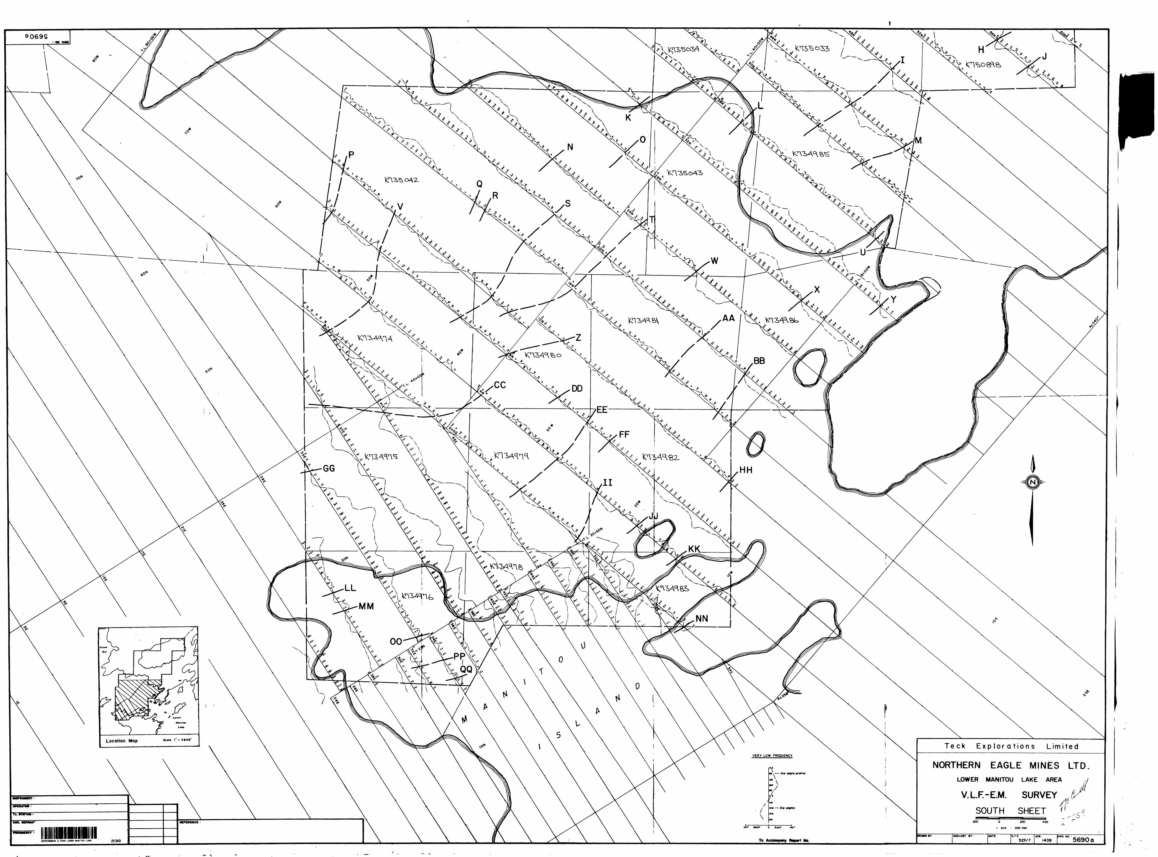
On the south grid, VLF-EM and magnetometer surveys were
l completed on all cross-lines at 50 foot intervals using the
Scintrex Integrated Portable Geophysical System,
l Magnetometer readings were corrected for diurnal change
using a base station located on Manitou Island. The Cutler,
Maine station was used as the transmitter for the VLF-EM
l survey.
l
l
l
l
Results
l Geophysics
A total of 43 VLF-EM conductors were located. Two of
these are possible bedrock conductors (H, I) and the
remaining 41 are caused by surficial conductivity or weak

lB ionic conductivity. The conductors are predominantly weak,
j of short length, with only background magnetic signature.
32 of the surficial conductors are located in the lake.
lThe magnetic data was contoured to aid in
l interpretation of the geological trends. Highs are rare and
j very small. Overall trend indicates a strike direction of
N40 0 E. The highest magnetic reading is approximately 2,500
l gammas above background and is situated in the
central portion of the property. Magnetically, the property
l is relatively flat.
ll CONCLUSIONS
l VLF-EM and magnetic surveys revealed two possible
M bedrock conductors and several magnetically high lenses.
The VLF conductors may represent weak sulphide bodies or
l ionic conductors such as wet shear zones. Gold deposits in
the area are associated with both of these.
l
RECOMMENDATIONSl
lAs a first step in the 1984 summer field program it is
l recommended that the land portions of the property be
geologically mapped. In conjunction with this, the VLF-EM
l

l l l l l
conductors and rare magnetic highs on land should be
prospected and sampled if explained in bedrock.
REFERENCES
Burton, G.B. and Hodge, H.J., 1983, Report on Manitou
Straits Property, Manitou Lakes Area, District of Kenora,
l Ontario for Northern Eagle Mines Ltd.
l
l
l
l
l
l
l
l
l
l
l
l
F TH-66

l l l l l l l l l l l l l l l l l l l
GEOPHYSICS LEGEND
MAGNETOMETER SURVEY (MAG.) SELF-POTENTIAL SURVEY (S.P.)
•TO gommoi1190
1840
1110
•40
INSTRUMENT : Operator i
All Voluee Ntgollvi
•90Pollliv* Anomaly
looo Arbitrary Bait
11*0Negative Anomaly
INSTRUMENT i Operator i
ELECTROMAGNETIC SURVEY
10" T
NORTH aEAST TILTS
O-
SOUTH D WEST TILTS
BROADSIDE
r SOIO Hi.
r 1830 Hi.
• ZOUnitl
l r 390 Ut. s\"~.\ Trartsmitttr pot/Hot
x".^:;^'--^ oroottstdt travirtt
- Broodtldt frotllt
INSTRUMENT t Operator i
4'OOW •ZOUnlli
P.E.M.
l*N Ctonntl t
4 10 Mill j
t ' \Ctionntl S
-J Ctll li*.
FIXED TRANSMITTER
INSTRUMENT Optrator i Coll Sip. ' Frtqutncy '
SHOOTBACK (Horizontol aCo-Axiol)
80" -
NORTH 8 EAST TILTS
o.
SOUTH a WEST TILTS
1 {
VE10" -
NORTH a EAST TILTS
0-
SOUTH 8 WEST TILTS
1
r 1830 Hi.
* . '-L. r J#0*'.
f \J/' "*^*^.*-^:i Transmitter petition
*"\^V *^\^"^^••^*/7 —— Ktctlvtr profiltt
lo* ^^l^* \ dttoll frortrif
————————————— * —————— . zoe.Tronsmttttf nt-up . lor o'tloil |
NSTRUMENT i i )perolor i-
RY LOW FREQUENCY (V.L.F.)
* 0 I0 I0 0""A--1 *\l \ (0 1 Fltttr tola frefili
i 10 lt\' ts 10 It l 1 i fv1 W'l^-^"*"*"*o* * \-L c
1NSTRUMENT i 1 2pirotor t n.- Station i
r SOIO Hi.
\j\rl8SOHt.* ""' L'^x 390Hr -/^••N^K — ^/^ Angli Proftlt
•"'^'v.'x' j '^1 ————— 1 Ctll tit.
1STRUMENT t operator i oil Sep. i
MoxMin (H. E. M)
'..HW |
L Vr/J"'"""
INSTRUMENT i )ptrotor i , :oll Stp. i
- METRIC

lli i i i i i i i i i i i i i if-"' l
l
CRONE GEOPHYSICS LIMITED
3607 WOLFEDALE ROAD, MISSISSAUGA, ONTARIO, CANADA.
Phone: (416) 270-0096
AN EM RECEIVER MEASURING
THE FIELD STRENGTH, DIP ANGLE AND QUADRATURE COMPONENTSOF THE VLF COMMUNICATION STATIONS
FIELD STRENGTH materBATTERY test and "STEADY" or "KEYED" signal switchesINCLINOMETER
FIELD STRENGTH range switch
VOLUME CONTROL ON-OFF switch
STATION SELECTOR switch
BATTERY COMPARTMENT (inside)
CONDUCTOR DIRECTION ARROW SPEAKER
This is a rugged, simple to operate, ONE MAN EM unit. It can be used without line cutting and is thus ideally suited for GROUND LOCATION OF AIRBORNE CONDUCTORS and the CHECKING OUT OF MINERAL SHOWINGS. This instrument utilizes higher than normal EM frequencies and is capable of detecting DISSEMINATED SULPHIDE DEPOSITS and SMALL SULPHIDE BODIES. It accurately isolates BANDED CONDUCTORS and operates through areas of HIGH HYDRO NOISE. The method is capable of deep penetration but due to the high frequency used its penetration is limited in areas of clay and conductive overburden.
The DIP ANGLE measurement detects a conductor from a considerable distance and is used primarily for locating conductors. The FIELD STRENGTH measurement is used to define the shape and attitude of the conductor.

l
l
l
l
l
l
l
l
l
l
l
l
l
l
-l l
tl V' *"-- k
^.l f*-^,i-.^ ' "-"V . * ^
^i;io,*.Kr.^-
The MF-2 is a completely new concept in vertical force fluxgate magneto-motors. These instruments, which ore designed for fast and accurate mineral ground surveys, arc orientation independent, self levelling and require no tripod. The MF-2 combines the electronics and sensor in one compact 3 3/^ Ib. package. An external dry cell battery pack is provided as standard power source for the instrument. As an'Option, recharge able batteries may be provided and housed direct ly in the instrument.With the latest I.C. and F.FT. circuitry and high precision components, a temperature stability bet ter than 1 gamma per C is standard (with .25 gamma on special order) over a range of —40 ' to -HO'C.The instrument has a built-in hemisphere polarity switch providing two overlapping ranges, for the Northern hemisphere the full range is -f 80,000 to —20,000 gammas, and reversible for the Southern hemisphere.A calibrated feedback system can be provided which makes it possible to determine the total vertical component strength.Measuring resolution, on the 100 gamma scale (optional) is 0.5 gamma, and on the 1000 gammac m l r* ic K n,'i m m.'i Q
\MiiMi irTirj-mttoirT
same electronics and specifications as the MF-2, but the sensor is detached and enclosed in a small cylindrical tube which permits it to be oriented and tilted in any desired direction. A 25 foot cable connects the sensor to the instrument housing. This version is particu larly suitable for the study of the magnetic properties of rocks, and the measurement of magnetic field components of any orientation, etc
b) MF-2GSThe MF-2GS Magnetometer has the same electronics and specifications as the MF-2 but has two sensors, the enclosed self-levelling sensor of the MF-2 as well as the detached geoprobe of the MF-2G, either one of which can be employed at any one time. Thus, this instrument can be employed as the standard MF-2 and for the determination of the magnetic properties of rocks, etc.
c) MF-2-100100 gammas and 300 gammas full scale ranges are added to the standard MF-2 and its options.

I Scintrex has used low power consumption microprocessors and high
• density memory chips to "create the IGS Integrated
• Portable Geophysical System; instrumentation which will change the way
•you do ground geophysics.
• here are the main benefits 'which you will derive from
the IGS family of instrumen tation:l1. You will save time and
I money ip the acquisition, processing and presenta tion of ground geophysi-
I cal survey data.
2. You will achieve an im-
I provement in the quality of data through enhanced reading resolution, an in crease in the number of different parameters measured and/or a higher density of observations.
l l
3. Your operator will ap-
I preciate the simplicity of operation achieved through automation.
|4. Since add-on sensors are relatively less expensive,
I 'your investment in a range of IGS instrumentation may be much less than it
— would be with a number l of different instruments,
each dedicated to a dif ferent measurement.
iwvw
l
7ftO Scintrox IGS-2/MP-4/VLF-4 permits ono operator to v/ticioiWy measure both magnetic and VLF fields end lo record data in computer compatible solid-state memory,

Description
Block diagram showing how the IGS-2 can be complemented by VLF-4 and MP-4 options to function as a VLF receiver and/or magnetometer.
Duat Col! VLF " Magnetic FieldSensor
VLF - Electric Field Dipole
/ Two VLF Processing Circuit Boards
/C
Program EPROM
VLF-4VLF Electromagnetic Sensor Option
Keyboard DisplayMicroprocessor Memory
IGS-2System Control Console
Total Held or Gradiometer Sensor
l l l l i i i liti
j
i i
Summary of Important Features of Scintrex MP-3, VLF-3 and IGS Based Instrumentation
• Common Features Magnetics VLF
l Magnetometer~~7 Processinp
Circuit Boa;d
j——-j. Program 1 l TT l* EPROM
MP-4Proton Magnetometer Sensor Option
l(
ll
ll
ll
l
l l
Simple operation via keypad32 character LCD displayDisplays present and previous dataAlarm and warning messagesensure data quality'Speaks' any language with LatincharactersSolid-state memory expandable tohold several days' dataRecords actual coordinatesRecords timeRecords header InformationRecords ancillary dataPermits revision of dataOutputs to commonly available.printers, modems, tape recordersand microcomputersPrints data lists and plots profilesdirectly on a digital printerOrganizes data by grid, lino andstation number, regardless of theorder In which data wore takenSeveral power supply optionsWide operating temperature range
Additional features found in both MP-3 and IGS-2/MP-4.
0.1 gamma resolution over 20K to 100K gamma range Total field and vertical gradient measurements High gradient tolerance Same console for portable, base sta tion or mobile survey applications Keyboard selectable automatic or manual tuningAutomatic diurnal correction without a microcomputer
Additional features found only In IGS- 2/MP-4.
* The VLF-4 VLF Electromagnetic Sensor Option can bo added so that one operator can make both magnetic and VLF readings
Additional features found in both VLF-3 and IGS-2/VLF-4.
* Measures both VLF-magnetic and VLF-electric fields
* Values are normalized by thehorizontal vector amplitude, to over come errors due to varying primary field strengths
* Calculates resistivity and phase angle
* Digital tuning to any VLF station* Automatic measurement of up to
three VLF stations* Automatic tilt compensation* Signal/noise enhancement through
automatic signal stacking* Automatic gain adjustment
Additional feature found only In IGS- 2/VLF-4
* The MP-4 Proton Magnetometer Sen sor Option can bo added so that one operntor can make both magnetic and VLF readings

w'O
2.7259 LOWER MANITOU LAKE 900
L .:-,: r : i, hi t id. P -ys Ci." i " '
J i/ \ : -. ! *:'o A1 .
(l \-\ k '-'AG) i Lower Manitou Lake - M2007"R."j."v;'r?oht ! P' c-', r-f r ' o* 'f L k f r * r f- No.
A38823
P.O. Box 10, l Hrst Canadian Place, Toronto, Ontario, K5X l A2|E . ^f y Co- :.i-nv
Teck Explorations Limited|Dste o) Fjrvey (fiorn f,' to)
i 10 01 84 115 03 84j n?y Wo. l Yr. j Day [ Mo. j Yr,
l :i:t,l Mile; of line Cut19.7
K. Trioi'srii, 2 i 89 Aloonauin Avenue, uorih Bay, Ontario, F3B 'J 73
20
F o- i rt l. i ciui'.ior.a! survey: u-jiric \ lit Sr.'ne p' id:
E r,if i ?0 fiays (for tech) [
Gfc^chernical
- xfj-'. iiDiv.j't'F. tC'xciiioc: poxYC'i sti ippint))
ir .. . -""'T' C* '"^ i i --.-::™:-;,j:::i,: |l^
lci'lciiion of E xpenditurt' Dfiys Credits
T ci*! F x EI* ndil Lir esTotal
De yf C' cc
l n s * f u c 11 Ci n slot&l Deys Credits, may t't apportionnd at the- claim holoer's choice. FnU:r number of Ofiys c f td i t*, pt-f ciamt selected in colun'ins at tipht.
\
K j 734974 ,
734975
; 734976
; 734978
734979
734980
1 734981
734982
734983
734035
i 734^6
735023
, 735024
735031
'. 735032
j 735033
'. 735034
735042
735043
: 750895
750896
-
1
t
1
4
' V
* t
*
t
B
*
t
Df.ys Gr.
- -
.... ...—
tetfyl?H?d
--
- - —
f4
N'iinirip Cih-rn Pr ef (X N'urnhfcT
ij
- . . . , .
- - - - -
i
j V'S Cr.
fc j s **1 f\ S* ^^ t f"^ Total number of mining j ||'A 7^2 7 x X ^ ~sr,tbv 1his l JL J
l Ret orcifd Hcil6t-r of Atitni (SipriftT ure) |
l.-.^^.-.:--J
__L2iPilLc yiL2nl^loia! Day^ Cr.lDf.tt; Recorded
July 20, 1984 ^ ^ ^^ ^
Q^l^^-i'^i'^' ^' er ^y in ? Rfcpor; o| Woik^ _ ^ ^ .^, - , __ _________ f _ ^vL. __l.^ __ -—l fif-tftiy fcrtiiy if'.cU ! have K personal csnd i mi mat e knowSfcdot of tht facts set forth iri the Report oi Work anneyied hf^ro, havirig performed t hi work or vviinessi't: senif during ariC! ;oi bitei it^ completion end t li f eirincxed ifcpon as true. —
N kT^ioFst'f? c,' 0 Ti8 19ffAlgonr 'qu lfn Avenue, North Bay, Ontario, P1B 423Date Certified
July 20, 1984Certified L, :?f8 r'S'

l l l l l l l l l l l l l l
l l
Ontario
Ministry of Natural Resources
GEOPHYSICAL - GEOLOGICAL - GEOCHEMICAL TECHNICAL DATA STATEMENT
File.
TO BE ATTACHED AS AN APPENDIX TO TECHNICAL REPORTFACTS SHOWN HERE NEED NOT BE REPEATED IN REPORT
TECHNICAL REPORT MUST CONTAIN INTERPRETATION, CONCLUSIONS ETC.
Type of Survey(s). Township or Area. Claim Holder(s)—
Geophysics, EM, MAGLower Manitou Lake AreaR.J. Wright
Survey company Teck Explorations Limited Author of Kppnrt T.N.J. Hughes_________Address of Author 2189 Alqonquin Ave, North Bay, Ontario Covering Dates of Survey January to March 1984_______
(linecutting to office)
Total Miles of Line r.nt 19.76___________________
SPECIAL PROVISIONS CREDITS REQUESTED
ENTER 40 days (includes line cutting) for first survey.ENTER 20 days for each additional survey using same grid.
Geophysical
—Electromagnetic.—Magnetometer——Radiometric———Other——————
DAYS per claim
20
Geological.Geochemical.
AIRBORNE CREDITS (Special provision credits do not apply to airborne surveys)
Magnetometer. .Electromagnetic . Radiometric(enter days per claim)
DATE- Oct. 1.1984 SIGNATURE:Author~of Report or Agent
Res. Geol..o
. Qualifications rv'
Previous Surveys File No. Type Date Claim Holder
MINING CLAIMS TRAVERSED List numerically
K 734974(number)
;........j^49Lza....................
.X..........7.3.4S.82.
.^..........734.9.86.
.K..
K
735024
..K.
..^. ..73503.3.
3
TOTAL CLAIMS——21
837 (5/79)

GEOPHYSICAL TECHNICAL E
GROUND SURVEYS - If more than one survey, specify data for each
Numher of Stations M3Q 1925 EM 1940 N,,mhe,
(ATA
type of survey J^f
rofReadinas Mad 1925 EM 1940
Station interval 50 feet Line spacing 400 feet
Profile scale 1 inch * 40 O
Contour interval lOOqammas
Instrument Scintrex MF-2 Sr.1nt.rpx TGS-P/MP-dH Arr-nracy - Srale constant i D.5% Of full SC3le ^.1
g niurnal correction method B3S6 Station
5 Basf Station ch^ck-in interval (hours) 24
Rase station location and value Mam'tou Island and Lower
gamma resolution over 20k to 100k
Manitou Lake
rii instrument Crone Radem VLF Unit Scintrex IGS-2/MP-4ft Coil configuration Horizontal S vertical25O Coil separation .
*H' Accuracy - 'f*-'0 -'*Q ^ Method: [^3 Fixed transmitter d Shoot backu Frequency 17.8kHz, Cutler, Maine*J (specify V.L.F. station)
Parameters measured Dip AnqleS Phase Angle
Instrument
Scale constant:*H Torrections made
(^ O Base station value and location
Elevation accuracy
Instrument
Z Method 1 1 Time Domain DO P Parameters — On timeM H - Off time*— 1 rtt! G ^ ^ —Delay time,, . .....J p 'c^ f-* *^ D tL Povi/er
D Electrode array — ————- ——————————————————————————Q 2; Electrode spacing —— ——— —————————————————————————t— i r o
Type of f]f ri rode .
D In line CD Parallel line
Frequency Domain FrequencyRange
1
1
1
1
1
1
1
1
1
1
1
1
1
1
1
1
1
1
1

1 1 1 1 1 1 1 1 1 1 1 1 1 1 1 1 1 1 1
0SELF POTENTIALInstrument
Survey Method
Corrections made
RADIOMETRICInstrument
Values measurer!
Enerpy windows (levels)
Height of instrument
Size of rletertor
Overburden
Ranpe
Background Count
(type, depth — include outcrop map)
OTHERS (SEISMIC, DRILL WELL LOGGING ETC.)
Type of survey
Instrument
Accuracy
Parameters measurer!.
Additional information (for understanding results),
AIRBORNE SURVEYSType of snrvey(s)
Instrument(s) —————————————————————————————————(specify for each type of survey)
Arriirary(specify for each type of survey)
Aircraft used
Sensor altitudeNavigation and flight path recovery method
Airrraft altitude
Miles flown over total area.
T.ine Sparing
Over claims only

GEOCHEMICAL SURVEY
Niimhers of rlaims from whirh samples taken.
Total Numher nf Samples.Type nf Sample
(Nature of Material) Average Sample Weight
Method "f f^olJertion
Soil Horizon SampledHorizon Development.Sample DepthTerrain
Drainage Development, . — ,—Estimated R?mpp "f fVerhmden Thickness
SAMPLE PREPARATION(Includes drying, screening, crushing, ashing)
Mesh si/e "f fraction used fnr analysis.
General,
- PROCEDURE RECORD jAx^
ANALYTICAL METHODSValues expressed in: per cent CD
p. p. m. Q p. p. b. D
Cu, Pb, Zn, Ni| 'Co, Ag, Mo, As.-(circle)
Others
Field Analysis ( tpsts)
Extrartion Methnd
Analytical Methnd
Reagents I Ised
Field Laboratory AnalysisNn. { tests)
Evtrartinn Method
Analytical Method -Reagents Used
Comrnerrial T.^horatory ( tects)
Name of V.ahoratory
KxtrS'-tinn Method,
Anfllytiral Method ,
Reapents Used
General ————————————————————————————
1
1
1
1
1
1
1
1
1
1
1
1
1
1
1
1
1
1
1

Mining Lands Section
Control Sheet
File No
TYPE OF SURVEY ^ GEOPHYSICAL
____ GEOLOGICAL
____ GEOCHEMICAL
EXPENDITURE
MINING LANDS COMMENTS:
Signature of Assessor
fi-O?
Date

Ministry o(NaturalResources
Ontario
Order of the Minister
The Mining Act
Room 6450, Whitney Block Queen's Park Toronto, Ontario M7A 1W3 416/965-1380
In the matter of mining claims:
734974-75-76734978 to 83 incl734985-86735023-24735031 to 34 incl735042-43750895-96
in the Area of Lower Manitou Lake,
R.J. WrightOn consideration of an application from the recorded holder,———under Section 77 Subsection 22 of The Mining Act, l hereby order that the time for filing reports and plans in support of
Geophysical (Electromagnetic R Magnetometer) a^tment work recorded nn -luly 25, iQ84be extended until and including October 3,____19 84
Data Signature*of Director, Land Management Branch
Copies:
R.J. WrightP.O. Box 10l First Canadian PlaceToronto, OntarioM5X 1A2Mining Recorder Kenora
cc: Teck Explorations Limited 2189 Algonquin Avenue North Bay, Ontario P1B 4Z3
1333 (82/1)

q 6899
Location Map
Te ck Exp lor a tions
MAGNETOMETER SURVEY
SCINTREX MAGNETOMETER
BLAKE CONTRACTING
Accompany
Limited
NORTHERN EAGLE MINES LTD,LOWER MANITOU LAKE AREA
MAGNETOMETER SURVEYNORTH SHEET 4
ft[y
200 6 400
l he h i 200
400 ,9VM P'' l
OftMNN BY'6.S.K.
CONTOURED.
B.G H.DATE iMAR.1984 52F/7
N.T.S. JO*1439
OWG NO 5689 b

Locution Mop Teck Exp lor a tion s Limited
MAGNETOMETER SURVEY NORTHERN EAGLE MINES LTD.LOWER MANITOU LAKE AREA
MAGNETOMETER SURVEYSCINTREX MF-2 MAGNETOMETER
FRED BLAKE CONTRACTING SOUTH SHEET
To Accompany Rfeport No52FC7NMM6 2.7259 LO1BI tMMITOU LAME

D 6899
Location Map
Te ck Explorations L mitedVERY LOW FREQUENCY
NORTHERN EAGLE MINES LTDLOWER MANITOU LAKE AREA
V.LF-E.M. SURVEYNORTH SHEET
O 200
l Inch ' 200 tt i t
40 0 WIST o IA*T 40*
To Accompany Rtpor? No. 5689 aS./2S8 UOW6R MANITOU LAKE
04.*_.^\r.' i
/'
s vvS *
, 7'
*fvk. J^. \. *
- v AN
^ X-.
o x v
V ^rvx^,\v4- : V f -®^* .*
Location Mop
2.7259 L01B) *MNITOU LAKE
-—- ^