Dynamic Behaviors of a Harvesting Leslie-Gower Predator-Prey Model

Research ArticleVolume 10 Issue 2 - July 2019DOI: 10.19080/OFOAJ.2019.10.555784
Oceanogr Fish Open Access JCopyright © All rights are reserved by Naik Muhammad
Assessment of the Dynamic Behaviors of Submerged Floating Tunnel Under a High-Speed Train LoadingNaik Muhammad1*, Zahid Ullah2, Zafar Baloch1 and Dong-Ho Choi2
1Department of Civil Engineering, Balochistan University of Information Technology, Engineering and Management Sciences, Pakistan2Department of Civil and Environmental Engineering, Hanyang University, South Korea
Submission: June 18, 2019; Published: July 18, 2019
Corresponding author: Naik Muhammad, Department of Civil Engineering, Faculty of Engineering & Architecture, Balochistan University of Information Technology, Engineering and Management Sciences, Takatu Campus, Quetta, 87300, Pakistan
Oceanogr Fish Open Access J 10(2): OFOAJ.MS.ID.555784 (2019) 001
IntroductionConnecting the opposite shores of lake, fjord, river, and sea
strait through a structure, has always been a challenging task for the engineers. When the width and depth of waterway crossing are large then it becomes very difficult and uneconomical to build the conventional structures such as cable-supported bridge, immersed tunnel or underground tunnel. In addition, the design complexity increases for the conventional structures when the width of the waterway crossing goes on increasing. This leads to the necessity to find new structural solutions for such straits [1,2]. An innovative structural solution that can cover the disadvantages of the conventional structures mentioned before is Submerged Floating Tunnel (SFT). SFT is sometimes known as the Archimedes Bridge, is based on the idea of utilizing the supporting capacity of water due to the Archimedes buoyancy [3,4].
Like other offshore structures, an SFT is subjected to extreme environmental conditions such as waves, currents, tsunamis, earthquakes. The dynamic behavior of SFT under waves and seismic loadings have been studied by many researchers. A numerical procedure for the analysis of SFT accounting for seismic excitation was developed by Fogazzi et al. [5]. A
procedure for the nonlinear dynamic analysis of SFT considering 3D multi-support seismic excitations and nonlinear drag forces due to steady current and wind waves was presented by Di Pilato et al. [6]. This work was improved and the dynamic behavior of SFT was evaluated using spatially varying seismic motion by Di Pilato et al. [7]. The structural analysis of SFT prototype to be built in Qindao Lake (PR of China) under environmental loads such as waves, currents and earthquakes were presented by [8] using commercial finite element tool ABAQUS. A more enhanced numerical procedure for the analysis of SFT considering the spatial variability of seismic excitations was developed by [9].
The mooring cables supporting SFT are assumed to remain in tension during the operation [5-8, 4] however there are possibilities of slacking mooring cables during operation under extreme waves, seismic events, or moving loads. When the motion of the tunnel goes large, the tension in the mooring cable might fall to a low level and the cable could become slack. The transition of the mooring cable from slack to the taut condition may cause an extreme tension in the mooring cable which is also known as snap tension [10-13]. The slackness of mooring cables under moving train load needs to be properly studied.
Abstract
Submerged floating tunnels (SFTs) are innovative structural solutions to waterway crossings and are more economical compared to the conventional structures such as cable-supported bridges, underground tunnels or immersed tunnels. The dynamic behaviors of SFT under real train loads is the primary design requirement of an SFT, However, it is not investigated using realistic train models. In this study, the China-star high-speed train is used to evaluate the dynamic displacements, internal forces and cable tensions of SFT. The tunnel is modeled by FEM, the cables are modeled by elastic catenary cables, and ocean waves and currents are modeled by Airy’s wave theory. The SFT displacements, bending moments and cable tensions were significantly influenced by moving trains. The SFT experienced extreme vertical displacements and there was a large drop in the minimum cable tensions. The mooring cables were slacked both by magnitudes and speed of the moving trains, which should be avoided for the safety of SFT. This study recommends the additional buoyancies for the stability of SFT subjected to high speed trains.
Keywords: Submerged floating tunnel (SFT); Dynamics of SFT; High-speed train; Catenary; Spectrum compatible ground motions; Regular waves
How to cite this article: Naik Muhammad, Zahid Ullah, Zafar Baloch, Dong-Ho Choi. Assessment of the Dynamic Behaviors of Submerged Floating Tunnel Under a High-Speed Train Loading. Oceanogr Fish Open Access J. 2019; 10(2): 555784. DOI: 10.19080/OFOAJ.2019.10.555784002
Oceanography & Fisheries Open access Journal
Since SFT is considered an alternative solution for transportation, moving load analysis or dynamic analysis under traffic loadings is a key demand of the structure but the research efforts are very limited regarding this problem. The modeling of the traffic vehicle dominates the accuracy of the analyzed dynamic responses of the vehicle-SFT system. Some simple vehicle models have been adopted in this area. A primary attempt was made by [14], who investigated the effects of two and three-dimensional added mass models on the response of SFT under single moving load. The SFT response under single moving load is also studied by [15]. Liang and Jiang [16] considered a sprung mass vehicle model and studied the vertical response of SFT. Recently Lin et al. [17] studied the dynamic responses of SFT using a simplified two dimensional coupled vehicle-SFT model. In this model, the mooring cables were simplified as horizontal and vertical springs. However, these simple models may not replicate the real trainloads. Therefore, a study considering a real train model is very important for the realization of SFT. More sophisticated train models have been developed and the dynamic responses of bridges under these trains have been evaluated [18-20]. However, such models need to be implemented for the dynamic analysis of SFT to replicate the realistic structural responses.
In this study, the dynamic problem of SFT is formulated, modeling the tunnel as FEM and mooring cables as catenary elements. The waves and currents were modeled by Airy’s wave theory. The spectrum compatible ground motions were used to simulated earthquake excitations. The dynamic responses of SFT under waves, ground motions and China-star high-speed trainloads are evaluated, and some useful conclusions are drawn from the numerical simulations.
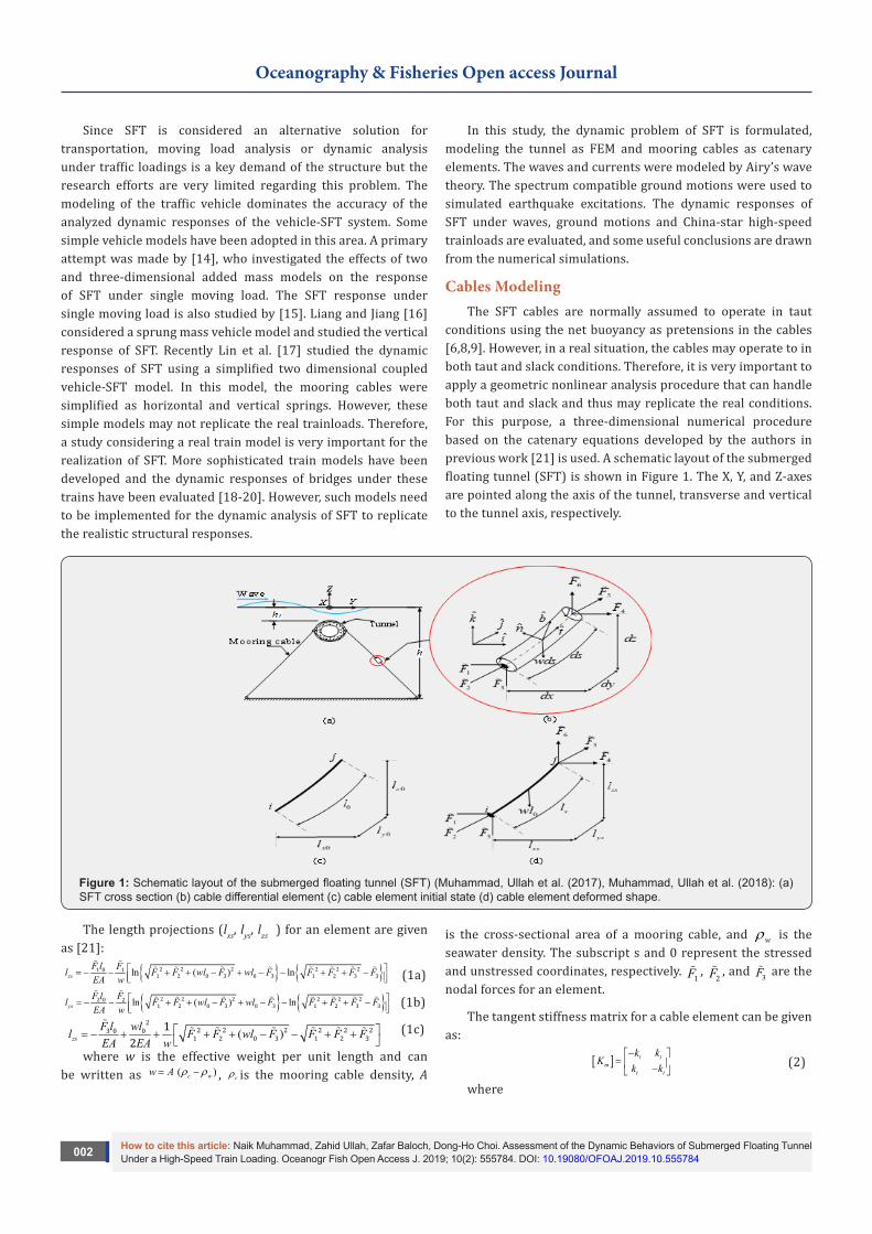
Cables ModelingThe SFT cables are normally assumed to operate in taut
conditions using the net buoyancy as pretensions in the cables [6,8,9]. However, in a real situation, the cables may operate to in both taut and slack conditions. Therefore, it is very important to apply a geometric nonlinear analysis procedure that can handle both taut and slack and thus may replicate the real conditions. For this purpose, a three-dimensional numerical procedure based on the catenary equations developed by the authors in previous work [21] is used. A schematic layout of the submerged floating tunnel (SFT) is shown in Figure 1. The X, Y, and Z-axes are pointed along the axis of the tunnel, transverse and vertical to the tunnel axis, respectively.
Figure 1: Schematic layout of the submerged floating tunnel (SFT) (Muhammad, Ullah et al. (2017), Muhammad, Ullah et al. (2018): (a) SFT cross section (b) cable differential element (c) cable element initial state (d) cable element deformed shape.
The length projections (lxs, lys, lzs ) for an element are given as [21]:
{ } { }ln ( ) lnxsF l Fl F F wl F wl F F F F FEA w
= − − + + − + − − + + − 2 2 2 2 2 21 0 1
1 2 0 3 0 3 1 2 3 3
(1a)
{ } { }ln ( ) lnysF l Fl F F wl F wl F F F F FEA w
= − − + + − + − − + + − 2 2 2 2 2 22 0 2
1 2 0 3 0 3 1 2 3 3
(1b)
( )zsF l wll F F wl F F F FEA EA w
= − + + + + − − + +
22 2 2 2 2 23 0 0
1 2 0 3 1 2 31
2
(1c)
where w is the effective weight per unit length and can be written as ( )c ww A ρ ρ= − , cρ is the mooring cable density, A
is the cross-sectional area of a mooring cable, and wρ is the seawater density. The subscript s and 0 represent the stressed and unstressed coordinates, respectively. F1
, F2 , and F3
are the nodal forces for an element.
The tangent stiffness matrix for a cable element can be given as:
[ ] t tm
t t
k kK
k k−
= − (2)
where

How to cite this article: Naik Muhammad, Zahid Ullah, Zafar Baloch, Dong-Ho Choi. Assessment of the Dynamic Behaviors of Submerged Floating Tunnel Under a High-Speed Train Loading. Oceanogr Fish Open Access J. 2019; 10(2): 555784. DOI: 10.19080/OFOAJ.2019.10.555784003
Oceanography & Fisheries Open access Journal
xs xs xs
ys ys yst
zs zs zs
dl dl dldF dF dF
f f fdl dl dl
k F f f fdF dF dF
f f fdl dl dldF dF dF
−
−
−
= = =
1
11 2 311 12 13
121 22 23
1 2 331 32 33
1 2 3
(3)
Where
( ) ( )ln j
i i i j j
T Fl FfEA w T F w T T F T T F
+ = − + + − − − +
260 1
113 3 6
1 1 1
(4a)
( ) ( )i i j j
F Ff fw T T F T T F
= = −
− +
1 212 21
3 6
1 1
(4b)
j i
Ff fw T T
= = −
113 31
1 1
(4c)
( ) ( )ln j
i i i j j
T Fl FfEA w T F w T T F T T F
+ = − + + − − − +
260 2
223 3 6
1 1 1
(4d)
j i
l F FfEA w T T
= − − +
0 6 333
1
(4e)
and iT F F F= + +2 2 21 2 3 and,
j i
Ff fw T T
= = −
223 32
1 1
jT F F F= + +2 2 2
4 5 6
. (4f)
Waves and currents modelingThe wave theories are normally based on water depth, wave
height, and wave period. The Airy wave theory, which holds for wave heights up to 10-15 m, covers a wide range and can consider significant waves of any actual sea states [22,23]. According to the Airy wave theory, the first-order velocity potential is given as follows [24]:
cosh[ ( )] sin
cosh( )gH k Z h
khα
ω+
Φ =2
(5)
where ( ) k Y ct kY tωα = ± = ± ; ( )/k π λ= 2 is the wave number; (=2 /T)ω π is the wave frequency; (= / )gTλ π2 2 is the wavelength
selected on the basis of deep-water criteria; H is the wave height; C is the wave speed, Y and Z are the vertical and transverse coordinates, respectively, having their origin at the free water surface; and h is the water depth. From the first-order velocity potential Φ , the water particle velocities in the transverse (Y) and vertical (Z) directions can be obtained as follows:
cosh[ ( )] cos
cosh( )gkH k Z hu
Y khα
ω∂Φ +
= =∂ 2
(6)
sinh[ ( )] sincosh( )
gkH k Z hvZ kh
αω
∂Φ += =∂ 2
(7)
Similarly, the water particle accelerations in the transverse and vertical directions can be given as follows:
cosh[ ( )] sin
cosh( )gkH k Z hu
khα+
=2
(8)
sinh[ ( )] coscosh( )
gkH k Z hvkh
α+= −
2
(9)
The calculation of hydrodynamic forces on the SFT is one of the primary and most challenging tasks during numerical simulations for dynamic analysis due to the involvement of the fluid-structure interaction phenomena [25]. Due to the random nature of ocean waves, complex nonlinear wave theories and lack of experimental evidence, it is difficult to describe the wave’s
exact effects on the SFT. However, simplified approaches, such as Morison’s equation, can be used to evaluate the hydrodynamic forces on the SFT and give reliable estimates as compared to experimental data [26,27]. The hydrodynamic forces from ocean waves and currents, acting per unit length of the SFT are given by the modified Morison’s equation as follows [4,23,24].
{ } ( ){ }{ } { }
( , )
( , )
i D w i i i i i i
M w i A w i
f q t C D w W q w W q
D DC w C q i
ρ
π πρ ρ
= ± − ± − +
− =2 2
12
1 24 4
(10)
where subscript i denotes the Y or Z direction; iw is the water particle velocity ( u or v ); iw is the water particle acceleration ( u or v); iW is the velocity (U or V ) of water currents acting at the centerline of tunnel and is obtained by linear equation:
[ ]( ) / cU h Z h U= − or [ ]( ) / cV h Z h V= − ; cU and cV are velocities of surface currents in Y and Z directions, respectively; iq and iq are the structural velocity and acceleration, respectively; wρ is the density of water; D is the external diameter of SFT; DC is the drag coefficient; and MC is the inertia coefficient; A MC C= −1 is the added mass coefficient. In Eq. (10), the first term on the right-hand side denotes the drag force, the second term denotes the inertia force, and the third term denotes the added mass effect.
The drag force is much smaller than the inertia [26], so the drag force term is linearized by removing the structural velocity term for numerical simplification. Substituting Equations (6)– (9) into Equation (10), the horizontal and vertical components of hydrodynamic forces in the Y-direction and the Z-direction can be obtained as follows:
( )
( )
cosh[ ( )] coscosh( )
cosh[ ( )] coscosh( )
YD D wgkH k Z hF C D U
kh
gkH k Z h Ukh
kY t
kY t
ρ ωω
ωω
±+
= ±
+× ±
±
12 2
2
(11a)
( )cosh[ ( )] sinco
h( )
sYI M w
D gkH k Z h tF Ckh
kYπρ ω+= ±
2
4 2 (11b)
( )
( )
sinh[ ( )] sincosh( )
sinh[ ( )] sincosh(
)
ZD D wgkH k Z hF C D V
kh
gkH k Z h Vk
kY t
kh
Y t
ρω
ω
ωω
+= ±
+× ±
±
±
12 2
2
(11c)
( )sinh[ ( )] coscosh( )
ZI M wD gkH k Z h kY tF C
khωπρ +
= − ±2
4 2 (11d)
where the subscripts YD and YI represent the fluid drag and inertia forces in the Y-direction respectively, the subscripts ZD and ZI represent the fluid drag and inertia forces in the Z-direction, respectively. The wave and current forces are obtained using the hydrodynamic conditions of Qiandao Lake. These forces acting on the SFT are calculated using Morison’s equation. During the numerical simulations, the drag forces and inertia forces were considered distributed loadings and were converted to equivalent nodal forces using the work-equivalence method [4,28]. The time history of these forces per unit length of SFT is shown in Figure 2. The transverse and vertical inertia forces are dominant hydrodynamic forces, while the drag forces are very small.

How to cite this article: Naik Muhammad, Zahid Ullah, Zafar Baloch, Dong-Ho Choi. Assessment of the Dynamic Behaviors of Submerged Floating Tunnel Under a High-Speed Train Loading. Oceanogr Fish Open Access J. 2019; 10(2): 555784. DOI: 10.19080/OFOAJ.2019.10.555784004
Oceanography & Fisheries Open access Journal
Figure 2: Wave force time history per unit length of the tunnel (H=1 m, T=2.3 s) [4].
Ground motions modelingThe submerged floating tunnel (SFT) prototype to be built
in Qindao Lake, China is taken as an example in this study. Due to unavailability of the real ground motions for the specific site, the spectrum compatible ground motions are generated for the analysis of the case study. The design spectrum shown in Figure
3, is based on the Code for Seismic Design of Buildings, GB 50011 – 2010 [29]. Where ( )gα is the seismic influence coefficient in units of g, maxα is the maximum seismic influence coefficient, Tg is the characteristic period, T is the natural vibration period of the structure, γ is attenuation index,η1 is the adjusting coefficient for slope, η2 is the damping adjusting coefficient and ζ is the damping ratio.
Figure 3: Seismic design response spectrum based on GB5001-2010 [29].
Table 1: Code specified values of the parameters [29].
Parameter Value
Group I
Site class II
Design basic acceleration of the ground motion 0.15g
Earthquake intensity 7
Tg 0.35 s
αmax (frequent earthquake) 0.12
αmax (rare earthquake) 0.72
Based on the geological and geotechnical conditions of the site the input parameters for the design spectrum are selected from the code GB5001-2010 [29] and are given in Table 1. The maximum seismic influence coefficient maxα is for horizontal ground motion. For the vertical ground motion, a 65% of the horizontal maximum seismic influence coefficient is used. The limitations and scarcity of the recorded ground motions along with the wide use of dynamic time history analysis for obtaining
the structural responses have motivated the simulation of the earthquake motions [30]. These simulated earthquake motions can be generated as a random process with a selected envelope shape and a Power Spectral Density Function (PSDF). The common model for generating earthquakes is that of superimposing sinusoidal components with random phase angles. In this study the code compatible ground motions were generated using the procedure described by [30].
The Comparison of design spectrum and response spectrum based on the Code for Seismic Design of Buildings, GB 50011 – 2010, People’s Republic of China, considering the rare earthquake scenario for the horizontal component of earthquake is shown in Figure 4a, and the design spectrum compatible artificial ground motions is shown in Figure 4b. Similarly, the comparison of the design spectrum and response spectrum for the vertical component of earthquake is shown in Figure 5a, and the code compatible ground motions are shown in Figure 5b. The elastic response spectrum calculated based on the generated artificial ground motions closely agree with the target/design spectrum.

How to cite this article: Naik Muhammad, Zahid Ullah, Zafar Baloch, Dong-Ho Choi. Assessment of the Dynamic Behaviors of Submerged Floating Tunnel Under a High-Speed Train Loading. Oceanogr Fish Open Access J. 2019; 10(2): 555784. DOI: 10.19080/OFOAJ.2019.10.555784005
Oceanography & Fisheries Open access Journal
Figure 4: The artificial time history of the horizontal ground motion acceleration compatible with GB 50011 – 2010 [29] (a) comparison of the horizontal design spectrum and response spectrum; and (b) time history of the horizontal ground motion acceleration
Figure 5: The artificial time history of the vertical ground motion acceleration compatible with GB 50011–2010 [29] (a) the vertical design spectrum and response spectrum; and (b) time history of the vertical ground motion acceleration.
Figure 6: SFT under simplified moving trainloads.

How to cite this article: Naik Muhammad, Zahid Ullah, Zafar Baloch, Dong-Ho Choi. Assessment of the Dynamic Behaviors of Submerged Floating Tunnel Under a High-Speed Train Loading. Oceanogr Fish Open Access J. 2019; 10(2): 555784. DOI: 10.19080/OFOAJ.2019.10.555784006
Oceanography & Fisheries Open access Journal
Trainloads ModelingSFT is a new alternative for transportation through sea
straits, fjords, and lakes. The dynamic response of SFT under vehicular loads or trainloads is not studied well to date. In order to evaluate SFT dynamic performance under real trains, the china-star high-speed train is used for simulating the SFT dynamic behavior. This study simplifies each axel of the moving train to a concentrated moving force P, as shown in Figure 6. Figure 6a is showing the dimension of the first three
cars for China-star high-speed train [31]. Figure 6 b shows the simplification of train loads to concentrated moving loads. Thus, a train composed of NP axels can be considered as NP moving loads, which are designated as Pk (k = 1, 2, 3, . . ., NP). The finite element formulations are used to calculate the load vector from k moving concentrated loads shown in Figure 7. To show that the kth moving load is located on a tunnel element (Shown in Figure 7c)) the step function is defined as
x<0( )
x>0H x
=
01
(12)
Figure 7: SFT under kth moving loads.
The ith tunnel element from the left side of the tunnel, its left node is located xil=(i-1)lt, where as its right node is located at xir=ilt and lt is the length of a tunnel element. At time t the location of the kth moving load is located by xk. The relative positions of the moving load to left and right nodes of ith tunnel element are [20,34]
,k i k ilx x x= − (13a)
,k i k irx x x+ = −1 (13b)
The step function then becomes
( ) ( ), , ,k i k i k iH H x H x += − 1 (14)
which has a nonzero value when the moving load is located on the tunnel element.
The nodal loads can be established by linking the kth moving load with ith tunnel element using the shape function. The shape function vector converts the vertical loads into equivalent nodal
loads. The shape function for kth moving load and ith tunnel element is
{ }
( ) ( )( ) ( )
( ) ( )( ) ( )
, ,
, , ,
, ,
, ,
, , ,
/ /
/ /
/ /
/ /
k i te k i te
k i k i te k i te
k i k i
k i te k i te
k i k i te k i te
x L x L
x x L x LN H
x L x L
x x L x L
− + − + = − −
2 3
2
2 3
1 3 2
1 2
3 2 (15)
The {Nk,i} is assembled for Nele elements to get {Nk}, and the nodal force vector from all the moving loads at time t is given as
{ } { } { }T Tk kP N P P P= − 1 2 (16)
Equations of MotionThe equations of motion for the SFT subjected to waves,
multi-support seismic excitations, and moving trainloads can be written as [2]

How to cite this article: Naik Muhammad, Zahid Ullah, Zafar Baloch, Dong-Ho Choi. Assessment of the Dynamic Behaviors of Submerged Floating Tunnel Under a High-Speed Train Loading. Oceanogr Fish Open Access J. 2019; 10(2): 555784. DOI: 10.19080/OFOAJ.2019.10.555784007
Oceanography & Fisheries Open access Journal
[ ] { }{ }
[ ] { }{ }
[ ] { }{ }
{ }{ }
( )
( )
g g gsr sr sr
T T Tg g gg gg g gg g gg
eff
M M C C K Kq q q
q q qM M C C K K
F t
p t
+ + =
(17)
where the subscript sr represents the unrestrained degrees of freedom (DOFs) in the system including both tunnel and cables DOFs, and g represents the support DOFs. The time-dependent force vector {F(t)} is given as
{ } { } { }( ) ( )F t f t P= + (18)
where f(t) are time-dependent wave (hydrodynamic) forces. The vector {P} is due to moving trainload. The Peff(t) is the effective seismic forces at the supports. This vector can be given as
{ } [ ][ ]{ }eff gp M i u= − (19)
where
[ ] [ ] gi K K− = − 1 (20)
where [i] is the influence matrix; { }gu is the seismic ground motion acceleration vector acting at the supports.
The matrices [M], [K], and [C] are given as
[ ] [ ] [ ] [ ] [ ]t c at acM M M M M = + + + (21)
[ ] [ ] [ ]e cK K K= + (22)
[ ] [ ] [ ] [ ] [ ] [ ] [ ]e c t c at acC K K M M M Mβ β = + + + + + 1 2 (23)
where [Mt] is the mass matrix of the tunnel; [Mat] and [Mac] are the added mass matrices for the tunnel and cables, respectively; [Mc] is the mass matrix of the cables; [Ke] is the elastic stiffness of the tunnel; [Kc] is the nonlinear mooring cable stiffness; β1 and β2 are the Rayleigh damping coefficients; i j
i j
ωωβ ζ
ω ω=
+1
2, and
i j
β ζω ω
=+22
; ζ is the modal damping ratio; iω , jω are the ith and jth modal natural frequencies of the structure, respectively. For obtaining the damping matrix, 2.5% modal damping ratio was used [32].
The displacement {q} vector is given as
{ } { } { }{ }t cq q q= + (24)
where {qt} are the tunnel displacements and {qc} are mooring cable displacements and these matrices for a single element are given as { } [ ]Tt X Y Z X Y Z X Y Z X Y Zq q q q q q qθ θ θ θ θ θ= 1 1 1 1 1 1 2 2 2 2 2 2 (25)
{ } { }Tc X Y Z X Y Zq q q q q q q= 1 1 1 2 2 2 (26)
The damping matrix in Eq. (23) is based on the Rayleigh damping model. In the present study, the tunnel was modeled by 50 3D beam elements and each cable was modeled by 5 catenary elements. The solution of the non-linear equations of motion (Eq. (17)) is performed step by step using the Newmark average acceleration method for time integration and the modified Newton-Raphson method for the equilibrium correction [33].
Case StudyThe dynamic behaviors of SFT were simulated using the
described formulations for the SFT model, as shown in Figure 8, which is planned to be built in Qiandao Lake, China. Figure 8 shows the side view of SFT model used for numerical simulations; the SFT is supported at locations A, B, and C by mooring cables. The input parameters for the SFT tunnel, hydrodynamic and mooring cables are those used by [2,4] and shown in Table 2, unless mentioned otherwise. The hydrodynamic parameters are those measured at Qindao Lake [8].
Figure 8: Structural model of SFT used for numerical simulations.

How to cite this article: Naik Muhammad, Zahid Ullah, Zafar Baloch, Dong-Ho Choi. Assessment of the Dynamic Behaviors of Submerged Floating Tunnel Under a High-Speed Train Loading. Oceanogr Fish Open Access J. 2019; 10(2): 555784. DOI: 10.19080/OFOAJ.2019.10.555784008
Oceanography & Fisheries Open access Journal
Table 2: Parameters of SFT tunnel, mooring cables and hydrodynamics [2,4].
Element Parameter Unit Value
Tunnel
Tunnel equivalent density kg/m3 2,451
Elastic modulus N/m2 3×10¹⁰
Area m2 5.1
Moment of inertia m4 12.3
Length of tunnel m 100
Mooring cables
Elastic modulus N/m2 1.4×10¹¹
Diameter of cable m 0.06
Moment of inertia m4 6×10⁻⁷
Cable density kg/m3 7,850
Hydrodynamics
Wave height (H) m 1
Time period (T) s 2.3
Surface current velocity ( Uc)
m/s 0.1
Depth of water (h) m 30
Distance of SFT from free surface (h1) m 2
Density of water (ρw) kg/m3 1,050
Drag coefficient (CD) -- 1
Inertia coefficient [35] -- 2
Results and Discussion As submerged floating tunnel (SFT) is considered an
alternative for waterway crossings, therefore the dynamic analysis under moving load is a key structural demand. The dynamic response under simple moving loads is presented in the literature, however the application of more realistic moving loads needs to be carried out for the realization of this innovative structural solution. In this study, the dynamic responses of SFT are evaluated for the China-star high-speed train, the design speed of this train is 270 km/hr. The train speed vP has a range of 0-270 km/h in this study. The pretensions in the mooring cables are calculated from the net buoyancy and given in the Table 3. To evaluate the effect of moving trainloads on the responses of SFT, three load combinations are defined as: (1) Load combination 1 (LC1): in this load combination, the dynamic responses of SFT are evaluated under moving trainloads. (2) Load combination 2 (LC2): in this load combination, the dynamic responses of SFT are evaluated under waves and moving trainloads. (3) Load combination 3 (LC3): in this load combination, the dynamic responses of SFT are evaluated under waves, moving trainloads, and seismic ground motions (horizontal and vertical).
Table 3: Pretensions in the mooring cables.
Cable # C1 C2 C3 C4 C5 C6
Pre-tension (×106 N) 0.62 0.62 0.49 0.49 0.62 0.62
Figure 9: SFT displacements, cable top and bottom tensions at the location B, under different load combinations (vP=100 km/h, H=1 m, T=2.3s, ζ=2.5%)

How to cite this article: Naik Muhammad, Zahid Ullah, Zafar Baloch, Dong-Ho Choi. Assessment of the Dynamic Behaviors of Submerged Floating Tunnel Under a High-Speed Train Loading. Oceanogr Fish Open Access J. 2019; 10(2): 555784. DOI: 10.19080/OFOAJ.2019.10.555784009
Oceanography & Fisheries Open access Journal
The SFT displacements, cable top and bottom tensions at the location B, under the load combinations LC1, LC2 and LC3 are shown in Figure 9. The max positive responses under three load combinations, are shown in Table 4. The SFT experiences extreme vertical displacements due to the application of moving trainloads, from time 0 to 12 seconds when the trainload passes over the SFT. The train loads cause the tunnel to deflect downward that results in reducing the cable tensions as can be seen in Figures 9c to 9f. The cable tensions fall well below the pretensions in the cables and close to zero tensions. The extreme SFT downward deflections could result in slacking the mooring cables that may result in the snap loads or structural failure of SFT. The positive and negative envelop curves of SFT displacements and bending moments under the load combination LC1, LC2 and LC3 are shown in Figure 10. The SFT displacements, as well as the bending moments, increase when the load combination is changed from LC1 to LC3. The SFT experiences extreme vertical displacements (qZ) and vertical bending moments (MY) under
the moving trainloads. The trainloads cause to reduce the positive vertical displacements and increase the negative vertical displacements. The extreme downward vertical displacements cause extreme bending moments and reduce cable tensions. It can be concluded that there is a significant increase in the downward vertical displacements and bending moments under the moving trainloads. Therefore, it can be concluded that trainloads are the dominant loading for the design of SFT.
Table 4: Maximum positive SFT displacements, cable top tensions and bending moments under different load combinations.
Response LC1 LC2 LC3
qY (m) 7.30E-08 0.06869 0.07092
qZ (m) 0.0033 0.03189 0.03515
Top Tension at C3 (×106 N) 0.52035 0.80435 0.79096
Top Tension at C4 (×106 N) 0.52035 0.77077 0.80243
MY (×107 N-m) 0.46184 1.2018 1.30168
MZ (×107 N-m) 2.60E-06 2.48637 2.57656
Figure 10: Positive and negative envelop curves of SFT displacements and bending moments under different load combinations (vP=100 km/h, H=1 m, T=2.3s, ζ=2.5%).
How to cite this article: Naik Muhammad, Zahid Ullah, Zafar Baloch, Dong-Ho Choi. Assessment of the Dynamic Behaviors of Submerged Floating Tunnel Under a High-Speed Train Loading. Oceanogr Fish Open Access J. 2019; 10(2): 555784. DOI: 10.19080/OFOAJ.2019.10.5557840010
Oceanography & Fisheries Open access Journal
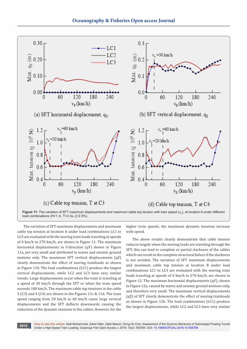
Figure 11: The variation of SFT maximum displacements and maximum cable top tension with train speed (vP), at location A under different load combinations (H=1 m, T=2.3s, ζ=2.5%).
The variation of SFT maximum displacements and maximum cable top tension at location A under load combinations LC1 to LC3 are evaluated with the moving train loads traveling at speeds of 0 km/h to 270 km/h, are shown in Figure 11. The maximum horizontal displacements in Y-direction (qY) shown in Figure 11a, are very small and attributed to waves and seismic ground motions only. The maximum SFT vertical displacements (qZ) clearly demonstrate the effect of moving trainloads as shown in Figure 11b. The load combinations (LC1) produce the largest vertical displacements, while LC2 and LC3 have very similar trends. Large displacements occur when the train is traveling at a speed of 30 km/h through the SFT or when the train speed exceeds 180 km/h. The maximum cable top tensions in the cable 3 (C3) and 4 (C4) are shown in the Figures 11c & 11d. The train speed ranging from 20 km/h to 60 km/h cause large vertical displacements and the SFT deflects downwards causing the reduction of the dynamic tensions in the cables. However, for the
higher train speeds, the maximum dynamic tensions increase with speed.
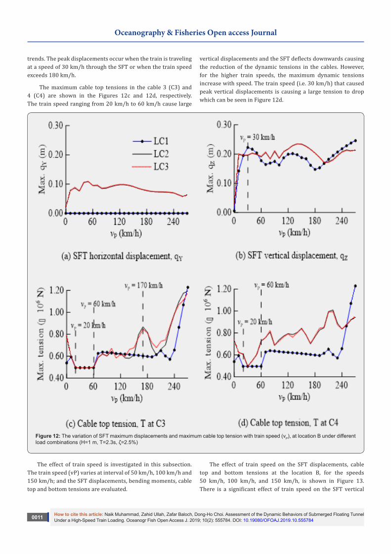
The above results clearly demonstrate that cable tension reduces largely when the moving loads are traveling through the SFT, this can lead to complete or partial slackness of the cables which can result in the complete structural failure if the slackness is not avoided. The variation of SFT maximum displacements and maximum cable top tension at location B under load combinations LC1 to LC3 are evaluated with the moving train loads traveling at speeds of 0 km/h to 270 km/h, are shown in Figure 12. The maximum horizontal displacements (qY), shown in Figure 12a, caused by waves and seismic ground motions only, and therefore very small. The maximum vertical displacements (qZ) of SFT clearly demonstrate the effect of moving trainloads as shown in Figure 12b. The load combinations (LC1) produce the largest displacements, while LC2 and LC3 have very similar
How to cite this article: Naik Muhammad, Zahid Ullah, Zafar Baloch, Dong-Ho Choi. Assessment of the Dynamic Behaviors of Submerged Floating Tunnel Under a High-Speed Train Loading. Oceanogr Fish Open Access J. 2019; 10(2): 555784. DOI: 10.19080/OFOAJ.2019.10.5557840011
Oceanography & Fisheries Open access Journal
trends. The peak displacements occur when the train is traveling at a speed of 30 km/h through the SFT or when the train speed exceeds 180 km/h.
The maximum cable top tensions in the cable 3 (C3) and 4 (C4) are shown in the Figures 12c and 12d, respectively. The train speed ranging from 20 km/h to 60 km/h cause large
vertical displacements and the SFT deflects downwards causing the reduction of the dynamic tensions in the cables. However, for the higher train speeds, the maximum dynamic tensions increase with speed. The train speed (i.e. 30 km/h) that caused peak vertical displacements is causing a large tension to drop which can be seen in Figure 12d.
Figure 12: The variation of SFT maximum displacements and maximum cable top tension with train speed (vP), at location B under different load combinations (H=1 m, T=2.3s, ζ=2.5%)
The effect of train speed is investigated in this subsection. The train speed (vP) varies at interval of 50 km/h, 100 km/h and 150 km/h; and the SFT displacements, bending moments, cable top and bottom tensions are evaluated.
The effect of train speed on the SFT displacements, cable top and bottom tensions at the location B, for the speeds 50 km/h, 100 km/h, and 150 km/h, is shown in Figure 13. There is a significant effect of train speed on the SFT vertical

How to cite this article: Naik Muhammad, Zahid Ullah, Zafar Baloch, Dong-Ho Choi. Assessment of the Dynamic Behaviors of Submerged Floating Tunnel Under a High-Speed Train Loading. Oceanogr Fish Open Access J. 2019; 10(2): 555784. DOI: 10.19080/OFOAJ.2019.10.5557840012
Oceanography & Fisheries Open access Journal
displacements, cable top, and bottom tensions. The absolute maximum SFT vertical displacements are 0.20 m, 0.20 m and 0.21 m when the train speed changes from 50 km/h to 150 km/h, respectively. Similarly, the minimum top tensions of the C3 are 0.48 kN, 0.49 kN, and 0.50 kN, when the train speed changes from 50 km/h to 150 km/h, respectively. The pretension (T0) in C3 is 495 kN, which means the dynamic tension drop well below the pretension under all moving speeds, especially high speed. If the dynamic tension in the mooring cable drops well below the pretension, the cable goes to slack condition or may cause the
snap tension in the cable [13]. It can be concluded that the high-speed trains vibrate the SFT more significantly; that can result in slack conditions which should be avoided for the safety of SFT.
The effect of train speed on the positive and negative SFT displacement and bending moment envelop curves, for the speeds 50 km/h, 100 km/h, and 150 km/h, is shown in Figure 14. The SFT displacements and bending moments increase with the increase of train speed. Increasing the train speed deflects the SFT extremely downwards which causes extreme negative bending moments.
Figure 13: Effect of the speed of moving trainloads on SFT displacements, cable top and bottom tensions at the location B (H=1 m, T=2.3s, ζ=2.5%)

How to cite this article: Naik Muhammad, Zahid Ullah, Zafar Baloch, Dong-Ho Choi. Assessment of the Dynamic Behaviors of Submerged Floating Tunnel Under a High-Speed Train Loading. Oceanogr Fish Open Access J. 2019; 10(2): 555784. DOI: 10.19080/OFOAJ.2019.10.5557840013
Oceanography & Fisheries Open access Journal
Figure 14: Effect of the speed of moving loads on the positive and negative SFT displacement and bending moment envelop curves (H=1 m, T=2.3s, ζ=2.5%)
ConclusionA submerged floating tunnel (SFT) is considered economical
alternative for waterway crossings compared to classical solutions such as cable supported bridge, underground or immersed tunnel. However, due to exposure of SFT to extreme environmental conditions and lack of research developments, an SFT is not constructed to date. The SFT response under moving trainloads is important from the design perspective and need to be evaluated under real trainloads. In this study, the dynamic responses of SFT under the trainloads using the data from China Star high-speed trains, are evaluated. The dynamic problem of SFT is formulated considering 3D tunnel and 3D cables. The tunnel is modeled by finite element method and cables are modeled by 3D catenary elements. The waves are modeled by Airy wave theory and wave forces are calculated by modified Morison’s equation. The nonlinear equations of motion of SFT
are integrated by Newmark’s average acceleration method and the Modified Newton-Raphson’s method is applied for equilibrium correction in each time step.
The SFT displacements, internal forces and cable tension are evaluated under waves, seismic excitation and high-speed trains. The SFT displacements, bending moments and cable top tensions are significantly influenced by moving trains. The SFT experiences extreme vertical displacements and there is a large drop in the minimum cable top tensions. This indicates that under the trainloads, the cable tensions will be reduced significantly, and slackness will happen. The slackness may lead to the snap tensions or to the structural failure of SFT if the SFT is supported only by net buoyancy in the vertical direction, which is key concept of the SFT. Therefore, additional buoyancies’ are recommended for the safe operation of SFT under high speed trains.

How to cite this article: Naik Muhammad, Zahid Ullah, Zafar Baloch, Dong-Ho Choi. Assessment of the Dynamic Behaviors of Submerged Floating Tunnel Under a High-Speed Train Loading. Oceanogr Fish Open Access J. 2019; 10(2): 555784. DOI: 10.19080/OFOAJ.2019.10.5557840014
Oceanography & Fisheries Open access Journal
AcknowledgmentWe acknowledge the Higher Education Commission (HEC)
Pakistan, for financially supporting the first author with the fully funded scholarship during the study period of this research.
References1. Martire G (2010) The development of submerged floating tunnels as
an innovative solution for waterway crossings, Università degli Studi di Napoli Federico II.
2. Muhammad N (2018) Dynamic Responses of Submerged Floating Tunnels with Mooring Cables under Waves, Earthquakes, and Moving Loads. Ph.D. Thesis, Hanyang University.
3. Faggiano B, R Landolfo and F Mazzolani (2005) The SFT: An Innovative Solution for Waterway Strait Crossings. IABSE Symposium Report 90(10): 36-42.
4. Muhammad N, Z Ullah and D H Choi (2017) Performance Evaluation of Submerged Floating Tunnel Subjected to Hydrodynamic and Seismic Excitations. Applied Sciences 7(11): 1122.
5. Fogazzi P and F Perotti (2000) The dynamic response of seabed anchored floating tunnels under seismic excitation. Earthquake Engineering & Structural Dynamics 29(3): 273-295.
6. Di Pilato M, F Perotti and P Fogazzi (2008) 3D dynamic response of submerged floating tunnels under seismic and hydrodynamic excitation. Engineering Structures 30(1): 268-281.
7. Di Pilato M, A Feriani and F Perotti (2008) Numerical models for the dynamic response of submerged floating tunnels under seismic loading. Earthquake Engineering & Structural Dynamics 37(9): 1203-1222.
8. Mazzolani F, R Landolfo, B Faggiano, M Esposto, F Perotti, et al. (2008) Structural analyses of the submerged floating tunnel prototype in Qiandao Lake (PR of China). Advances in structural engineering 11(4): 439-454.
9. Martinelli L, G Barbella and A Feriani (2011) A numerical procedure for simulating the multi-support seismic response of submerged floating tunnels anchored by cables. Engineering structures 33(10): 2850-2860.
10. Niedzwecki J M and S K Thampi (1991) Snap loading of marine cable systems. Applied Ocean Research 13(1): 2-11.
11. Plaut R H, J C Archilla and T W Mays (2000) Snap loads in mooring lines during large three-dimensional motions of a cylinder. Nonlinear Dynamics 23(3): 271-284.
12. Lu W, F Ge, L Wang, X Wu and Y Hong (2011) On the slack phenomena and snap force in tethers of submerged floating tunnels under wave conditions. Marine Structures 24(4): 358-376.
13. Hsu W t, K P Thiagarajan and L Manuel (2017) Extreme mooring tensions due to snap loads on a floating offshore wind turbine system. Marine Structures 55: 182-199.
14. Tariverdilo, S., J. Mirzapour, M. Shahmardani, R. Shabani and C. Gheyretmand (2011). “Vibration of submerged floating tunnels due to moving loads.” Applied Mathematical Modelling 35(11): 5413-5425.
15. Yuan Z, D Man-sheng, D Hao and Y Long-chang (2016) Displacement response of submerged floating tunnel tube due to single moving load. Procedia Engineering 166: 143-151.
16. Liang B and B Jiang (2016) Study on composition and simulation analysis of traffic loads in submerged floating tunnels. Procedia Engineering 166: 180-189.
17. Lin H, Y Xiang, Y Yang and Z Chen (2018) Dynamic response analysis for submerged floating tunnel due to fluid-vehicle-tunnel interaction. Ocean Engineering 166: 290-301.
18. Yang Y B, J D Yau and L C Hsu (1997) Vibration of simple beams due to trains moving at high speeds. Engineering Structures 19(11): 936-944.
19. Frýba L (2001) A rough assessment of railway bridges for high speed trains. Engineering Structures 23(5): 548-556.
20. Mu D, S G Gwon and D H Choi (2016) Dynamic Responses of a Cable-stayed Bridge under a High Speed Train with Random Track Irregularities and a Vertical Seismic Load. International Journal of Steel Structures 16(4): 1339-1354.
21. Muhammad N, Z Ullah and D H. Choi (2018) A numerical procedure accounting for fluid drag forces and cable extensibility for the static response of mooring cables. International Journal of Steel Structures 18(1): 293-303.
22. Brancaleoni F, A Castellani and P D Asdia (1989) The response of submerged tunnels to their environment. Engineering Structures 11(1): 47-56.
23. Muhammad N, Z Ullah, M W Park and D H Choi (2017) The role of cable stiffness in the dynamic behaviours of submerged floating tunnel. MATEC Web Conf 138.
24. Chakrabarti S K (1987) Hydrodynamics of offshore structures. In: WIT press.
25. Sarpkaya T and M Isaacson (1981) Mechanics of wave forces on offshore structures. In: Van Nostrand Reinhold, New York.
26. Kunisu H (2010) Evaluation of wave force acting on Submerged Floating Tunnels. Procedia Engineering 4(0): 99-105.
27. Seo S I, H S Mun, J H Lee and J H Kim (2015) Simplified analysis for estimation of the behavior of a submerged floating tunnel in waves and experimental verification. Marine Structures 44: 142-158.
28. Logan D L (2011) A first course in the finite element method. In: Cengage Learning, US.
29. China N S o t P s R o (2010) Code for seismic design of building. In: China Architecture and Building, Beijing, China.
30. Gasparini D A (1976) Simulated earthquake motions compatible with prescribed response spectra. M I T Department of Civil Engineering Research Report 76-74.
31. Xia H and N Zhang (2005) Dynamic analysis of railway bridge under high-speed trains. Computers & Structures 83(23): 1891-1901.
32. Veritas D N (2006) Free spanning pipelines. Recommended practice DNV-RPF105.
33. Chopra A K (2001) Dynamics of structures: theory and applications to earthquake engineering. In: (4th edn) Prentice-Hall, US.
34. Di M and D H Choi (2014) Dynamic responses of a continuous beam railway bridge under moving high speed train with random track irregularity. International Journal of Steel Structures 14(4): 797-810.
35. Wang C, H Cheong and S Chucheepsakul (1993) Static analysis of marine cables via shooting-optimization technique. Journal of waterway, port, coastal, and ocean engineering 119(4): 450-457.

How to cite this article: Naik Muhammad, Zahid Ullah, Zafar Baloch, Dong-Ho Choi. Assessment of the Dynamic Behaviors of Submerged Floating Tunnel Under a High-Speed Train Loading. Oceanogr Fish Open Access J. 2019; 10(2): 555784. DOI: 10.19080/OFOAJ.2019.10.5557840015
Oceanography & Fisheries Open access Journal
This work is licensed under CreativeCommons Attribution 4.0 LicensDOI: 10.19080/OFOAJ.2019.10.555784
Your next submission with Juniper Publishers will reach you the below assets
• Quality Editorial service• Swift Peer Review• Reprints availability• E-prints Service• Manuscript Podcast for convenient understanding• Global attainment for your research• Manuscript accessibility in different formats
( Pdf, E-pub, Full Text, Audio) • Unceasing customer service
Track the below URL for one-step submission https://juniperpublishers.com/online-submission.php