
Assessment of the capacity in European research...
73
Scientific and Technological Alliance for Guaranteeing the European Excellence in Concentrating Solar Thermal Energy FP7 Grant Agreement number: 609837 Start date of project: 01/02/2014 Duration of project: 48 months STAGE-STE deliverable 3.4 Assessment of the capacity in European research infrastructures to qualify standardized STE components WP3 – Task 3.4 Deliverable 3.4 Submitted: February 2018 Work Package Leader: US Task leader: ENEA Author(s): Walter Gaggioli, Luca Rinaldi (ENEA) Revised by: US Document version: 0 Reviewed/supervised by: N.A. Dissemination level PU
Transcript of Assessment of the capacity in European research...
Scientific and Technological Alliance for
Guaranteeing the European Excellence in
Concentrating Solar Thermal Energy
FP7 Grant Agreement number: 609837
Start date of project: 01/02/2014
Duration of project: 48 months
STAGE-STE deliverable 3.4
Assessment of the capacity in European
research infrastructures to qualify
standardized STE components
WP3 – Task 3.4 Deliverable 3.4
Submitted: February 2018
Work Package Leader: US
Task leader: ENEA
Author(s): Walter Gaggioli, Luca Rinaldi (ENEA)
Revised by: US
Document version: 0
Reviewed/supervised by: N.A.
Dissemination level PU

STAGE-STE task 3.4 “Adaptation of the STE Research Infrastructures
according to the new standardized STE components”
2
Table of contents
1. INTRODUCTION ................................................................................................................ 5
2. OBJECTIVE OF THIS REPORT ...................................................................................... 7
3. METHODOLOGY FOLLOWED ...................................................................................... 8
4. DESCRIPTION OF THE FACILITIES THAT ARE ALREADY AVAILABLE TO
QUALIFY THE NEW CST COMPONENTS (MS11) ....................................................... 11
5. ANALYSIS OF THE EXPERIMENTAL FACILITIES THAT COULD BE
EMPLOYED FOR THE QUALIFICATION OF THE STANDARDIZED CST
COMPONENTS ..................................................................................................................... 30
6. ASSESSMENT OF THE CURRENT CAPACITY OF ADAPTATION OF THE
QUALIFICATION FACILITIES OF EACH RESEARCH CENTRE, ACCORDING TO
THE NEW STANDARDIZED CST COMPONENTS ....................................................... 32
7. LIST OF ABBREVIATIONS ............................................................................................ 34
8. ANNEX 1 ............................................................................................................................. 34
9. ANNEX 2 ............................................................................................................................. 35
RECEIVER TUBES ........................................................................................................ 35
1-CENER – Indoor tests (optical and thermal loss) ................................................ 35
2-CIEMAT/PSA – Indoor tests (thermal loss) and outdoor tests (optical) .......... 36
3- CIEMAT/PSA –Indoor tests (optical) .................................................................. 37
4-ENEA – Outdoor test (thermal loss) ...................................................................... 38
5-ENEA – Indoor tests (thermal loss) ....................................................................... 39
6 -DLR – Indoor test (thermal loss) .......................................................................... 40
7- DLR Indoor test (optical) ..................................................................................... 41
8- DLR Indoor test (test for bellow fatigue) ............................................................ 41
9- DLR ( ageing test) ................................................................................................... 42
10- DLR (ageing cycling test) ..................................................................................... 42
11 DLR – Optical indoor test ..................................................................................... 43
HELIOST ......................................................................................................................... 44
1 - TEKNIKER ........................................................................................................... 44
2 - CYI ......................................................................................................................... 44
SOLAR THERMAL COLLECTORS ........................................................................... 47
1 - CIEMAT/PSA - ISO9806 ..................................................................................... 47
2 - CIEMAT/PSA ISO9806 ........................................................................................ 48
3- CNRS ....................................................................................................................... 49

STAGE-STE task 3.4 “Adaptation of the STE Research Infrastructures
according to the new standardized STE components”
3
4- LNEG ISO 9806 ...................................................................................................... 50
5 – ENEA EN 12975-2 AND ISO 9806 ACCREDITED LABORATORY ............ 51
6 – DLR TESTS ACCORDING TO STANDARD ISO 9806 ................................. 52
MIRRORS........................................................................................................................ 53
1 - CENER – Shape quality ....................................................................................... 53
2 - CENER – Mirrors durability (tests according to the iso 9227, iso 6270-
2,iso11507) ................................................................................................................... 54
3 - CENER – Mirrors reflectivity .............................................................................. 55
4 - CENER – Mirrors resistance to impacts (ISO 9806) ......................................... 56
5 - CIEMAT - Shape quality for linear ptc, dish , fresnel ...................................... 57
6 - CIEMAT - Mirrors durability outdoor aging (test according to ISO 9223 and
ISO 9226) ..................................................................................................................... 58
7 -CIEMAT - Mirrors durability accelerated ageing (different ISO) ................... 59
8 -CIEMAT/DLR - Reflectance evaluation .............................................................. 60
9 ENEA - Shape quality for linear fresnel concentrators ....................................... 61
10 -ENEA - Shape quality for linear ptc concentrators .......................................... 61
11 -ENEA - - Shape quality for dish reflectors ........................................................ 62
12 -ENEA - Profile quality ......................................................................................... 63
14 - ENEA - The reflecting surface ........................................................................... 64
15 - LNEG Reflectance evaluation in the solar spectrum (ASTM E903-12, ASTM
G173, ISO 9845-1) ...................................................................................................... 65
16 - LNEG - Mirrors durability outdoor aging (according to ISO 9223 AND ISO
9226) ............................................................................................................................. 66
17 - LNEG – Mirrors microstructural and surface characterization .................... 67
18 -DLR - Shape quality for ptc (geometric characterization of mirrors and
concentrators) ............................................................................................................. 68
19 - F-ISE - Shape quality for PTC ........................................................................... 69
20 F-ISE - Mirrors reflectivity (ASTMG173) .......................................................... 70
MISCELLANIES ................................................................................................ 71
1 - DLR Tracking system for trough solar collector (IEC TC 117/65) .................. 71
2 -F-ISE – Material ageing ......................................................................................... 72
3 - F-ISE – Glass optical characterization ................................................................ 73

STAGE-STE task 3.4 “Adaptation of the STE Research Infrastructures
according to the new standardized STE components”
4
List of figures and tables
Figure 1: Census Form ........................................................................................................................... 9
Figure2 – new FORM ........................................................................................................................... 11
Table 1 – Collection of the items of description of the experimental facilities present at the partners of
Task 3.4 . (MS11) ................................................................................................................................. 14
Table 2a – List of experimental facilities that could be employed for the qualification of the
standardized CST components (receiver tubes, solar collectors, heliostats)........................................ 30
Table 2b – List of experimental facilities that could be employed for the qualification of the
standardized CST components (mirrors, reflectors) ............................................................................. 31

STAGE-STE task 3.4 “Adaptation of the STE Research Infrastructures
according to the new standardized STE components”
5
1. Introduction
Economic operators demand increasing guarantees about the quality and safety of goods and
services purchased, on which the producers and the suppliers are called to guarantee for
compliance with technical requirements and to face competition in increasingly complex
markets.
Only accredited testing and calibration laboratories are able to provide the market with
reliable, credible and internationally accepted declarations of conformity.
Accreditation of a testing laboratory means the formal recognition, given by a third party, of
the laboratory's technical competence in carrying out certain tests: the accreditation is in fact
issued for individual tests and therefore must not be confused with a recognition extended to
the laboratory in its complex.
The accreditation of a laboratory for certain certifications of the laboratory's activities
complies with the requirements of the international standard ISO / IEC 17025: "General
requirements for the competence of testing and calibration laboratories". This standard refers
to the test laboratories, indicating with this the laboratories of chemical, chemical-physical,
microbiological, and mechanical and electrical testing. In addition to technical expertise, the
laboratory must demonstrate that it has put into practice the basic principles of every quality
management system (whose reference standards are those of the ISO 9000 series).
It is necessary to specify that there is a clear distinction between the certification against the
ISO 9001 standard of the quality management system of a laboratory - issued by a
certification body - and the accreditation according to the ISO / IEC 17025 standard of the
laboratory itself - issued by a national accreditation body.
The certification according to ISO 9001 does not constitute evidence that the laboratory is
able to provide accurate and reliable tests or calibrations. To be so, the laboratory must be
accredited in accordance with ISO / IEC 17025, which contains more specific requirements
for technical competence and impartiality, while also providing requirements for quality
system management to ensure that the laboratory provides reliable services.
Compliance with ISO / IEC 17025 requires a laboratory to adapt its operating and
organizational procedures with reference to two distinct and complementary categories of
requirements dictated by the standard itself:
1. Management requirements (very similar to those required by ISO 9001 and including
not only the structure of a document system describing in a clear and precise way the way in
which the laboratory is able to guarantee the reliability of the tests, but also related to the
organization and structure of the laboratory, the evaluation of suppliers, the management of
orders, the control of documents and data, the management of complaints, non-compliance,
corrective and preventive actions, internal audits and management system reviews for the
quality);

STAGE-STE task 3.4 “Adaptation of the STE Research Infrastructures
according to the new standardized STE components”
6
2. Technical requirements, including staff competence, management of instrumentation,
samples and reference materials, samples to be tested, testing, knowledge of measurement
uncertainty associated with testing, expression of results on a test report.
The test reports of accredited laboratories are recognized as valid in all countries that have
signed a mutual recognition agreement.
They are able to offer the market assurances of the reliability of the results of conformity
assessment services provided - tests, measurements and calibrations - precisely because of
accreditation and competence in carrying out tests and calibrations in accordance with
international standards.
The accreditation process provides an accurate assessment of all the elements that affect the
production of technical data, including:
Technical competence of the personnel;
Validity and suitability of the methods applied;
Metrological traceability of measurements and calibrations to national and
international samples of the SI system of measurement units;
Appropriate application of measurement uncertainty;
Suitability, calibration and maintenance of testing equipment;
Environmental conditions in which the tests are carried out;
Sampling, management and transport of test items;
Quality assurance of test and calibration data;
Participation of the laboratory in regular programs of evaluation tests or inter-
laboratory comparisons as a continuous demonstration of its competences.
In general, a laboratory is accredited to perform the tests required by European and
international standards for tests on specific components. For example in the field of low and
medium temperature solar thermal with regard to solar collector tests, the reference standards
are EN 12975- 2 and ISO 9806
Research activities in the field of high temperature solar thermal applications take the form of
technical-scientific support for the development of concentration prototypes (vacuum tube
receivers, linear and punctual parabolic systems, Fresnel lens systems), destined for heat
production both for powering thermal processes and for electricity production applications.
The success of the application of technologies based on the exploitation of high temperature
solar thermal is mainly linked to the development of:
a) innovative and competitive components, able to provide adequate services at low costs;
b) optimal technological solutions for each climatic condition.
In the experimental laboratories, the activity is focused on the analysis of the real functioning
of both the individual components and the plants, in order to allow the validation of the
optimization models developed that are used to determine the pay-back time of these types of
plants.
STAGE-STE task 3.4 “Adaptation of the STE Research Infrastructures
according to the new standardized STE components”
7
In general, in the context of research institutions, to create a station for the qualification of
solar components, several constraints must be considered. The first constraint is determined
by the fact that the experimental station must be used for research activities on high
temperature solar thermal applications.
This means that it must be considered that the experimental station will be used to test
different components solutions available both commercially and prototypes. (In the case of
solar collectors, for example, they are not different only for the technology used to
concentrate solar radiation but also for the size and characteristics of the materials used for
both the optical system and the receiver).
From this need emerges the need for the experimental station to be characterized by a wide
rangeability of its test parameters. For example, in the case of solar collectors, the
experimental station must be able to test the same in a wide range of flow and temperature in
order to guarantee the experimentation of the various commercial technologies available and
of the prototypes currently being developed and optimized.
A second constraint to consider for the construction of experimental stations to be used in
qualified (accredited) tests is represented by the need for the station's organizational system to
be able to elaborate specific studies on the test methods to be adopted for the energetic
characterization of the components.
In this framework the “Task 3.4 has the objective to determine the needs for adaptation of the
existing research centres’ facilities, through a conceptual design, or the needs of new ones, so
that the research centres have the appropriate installations (test equipment, laboratory, etc.)
for the qualification of the new standardized CST components”, whilst the specific CSP
components to qualify and the definition of the guidelines for standardization of CST
components was in charge at the activity of the WP5 - Relationship with Industry & Transfer
of Knowledge Activities
In the report, it has been proposed to adopt the terminology already adopted by ESTELA and
in the FP7 project EU-SOLARIS1, as follows:
The acronym CST (Concentrating Solar Thermal) is used to refer, in general, to the
technologies producing thermal energy with concentrated solar radiation.
2. Objective of this report
The objective of this task is to determine the needs for adaptation of the existing research
1 EU-SOLARIS is a FP7 Project, which aims to carry out the preparatory work needed for the creation of a large
distributed Research Infrastructure (RI) of European character and global reach. The main purpose of this
distributed RI is to foster, contribute to and promote the scientific and technological development of CST and
Solar Chemistry technologies. (www.eusolaris.eu)

STAGE-STE task 3.4 “Adaptation of the STE Research Infrastructures
according to the new standardized STE components”
8
centres’ facilities, through a conceptual design, or the needs of new ones, so that the research
centres have the appropriate installations (test equipments, laboratory, etc.) for the
qualification of the standardized CST components. In reason of this goal the work was carried
on in cooperation with the coordinator of the WP5 - Relationship with Industry & Transfer of
Knowledge Activities.
The following three results are also expected:
An exhaustive description of the facilities that are already available to qualify the new
CST components;
An analysis of the experimental facilities that could be employed for the qualification
of the standardized CST components;
An assessment of the current capacity of adaptation of the qualification facilities of
each research centre according to the new standardized CST components.
Due to the dispersion of the meanings of the acronyms employed in different scientific papers,
it is not always easy to identify with exactness the sector of reference and the kind of
components. This situation is the consequence of the absence of a standard terminology
universally accepted, and corresponds to one of the difficulty met during this work when it
has been necessary to define a criterion of classification of the CST technology components.
For this reason, another target of the report was to define a common terminology to employ in
the WP3 and WP5.
3. Methodology followed
On the base of the scope of the task 3.4, it was applied a methodology that scheduled the
execution of two different stages as explained below.
As a basis to define the methods of measurement for the characterization of the components
used in CST plants, have been used the instructions given in the report: “R12.4 Guidelines for
Testing of CSP components” elaborated in the framework of European project SFERA I (7th
Framework Programme).
As first stage, to evaluate the potential capacities of the existing installations available for the
qualification of the CST technologies components (among: CIEMAT-PSA, DLR, CNRS,
CYI, LNEG, CTAER, US, CENER, TECN, UEVORA, IMDEA, TKN, UNIPA, FBK, ENEA
and F-ISE), has been designed a census form that synthesizes the basic information useful to
evaluate the suitability of the different facilities, to be employed in the process of qualification
of the CST components
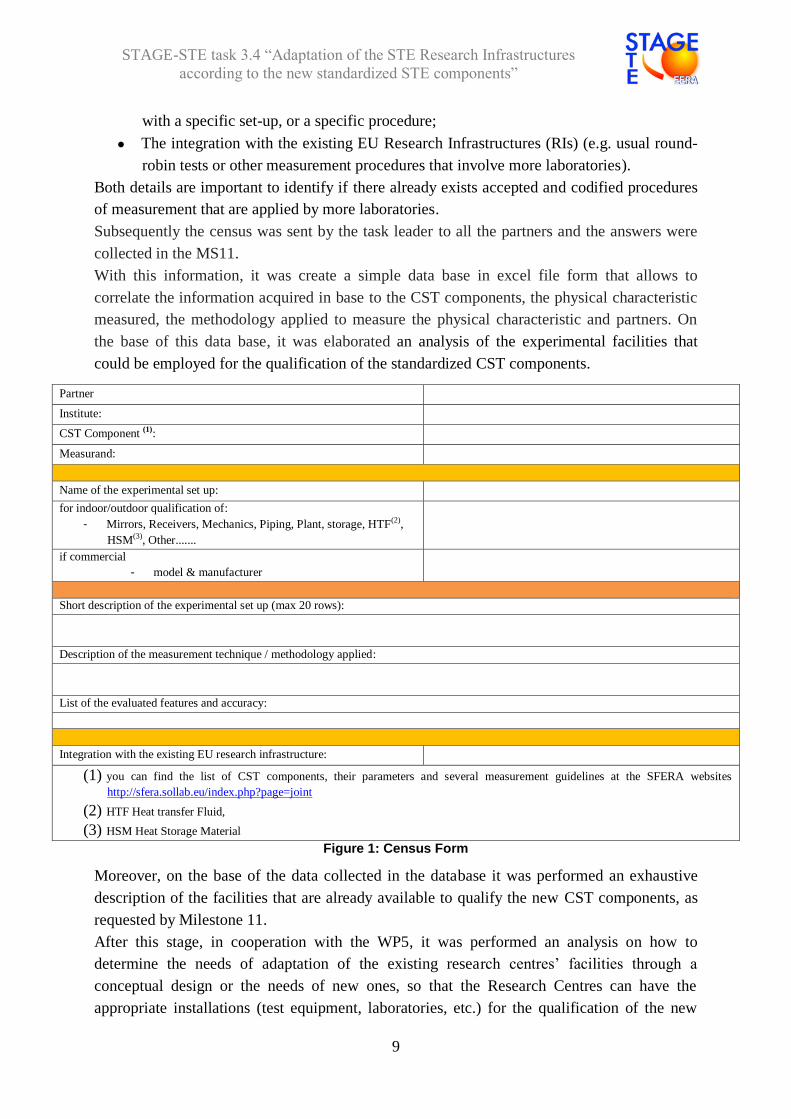
The format of the census form (see Figure 1) was elaborated with the support of the partners
and taking as reference the suggestions reported in the report R12.4 Guidelines for Testing of
CSP components. In the census form also the following requests have been included:
The list of the evaluated features and accuracy that can be assessed for each CST
technologies component. For example, for the mirrors the most important are
reflectance, shape and durability. This is because generally each feature is measured
STAGE-STE task 3.4 “Adaptation of the STE Research Infrastructures
according to the new standardized STE components”
9
with a specific set-up, or a specific procedure;
The integration with the existing EU Research Infrastructures (RIs) (e.g. usual round-
robin tests or other measurement procedures that involve more laboratories).
Both details are important to identify if there already exists accepted and codified procedures
of measurement that are applied by more laboratories.
Subsequently the census was sent by the task leader to all the partners and the answers were
collected in the MS11.
With this information, it was create a simple data base in excel file form that allows to
correlate the information acquired in base to the CST components, the physical characteristic
measured, the methodology applied to measure the physical characteristic and partners. On
the base of this data base, it was elaborated an analysis of the experimental facilities that
could be employed for the qualification of the standardized CST components.
Partner
Institute:
CST Component (1):
Measurand:
Name of the experimental set up:
for indoor/outdoor qualification of:
- Mirrors, Receivers, Mechanics, Piping, Plant, storage, HTF(2),
HSM(3), Other.......
if commercial
- model & manufacturer
Short description of the experimental set up (max 20 rows):
Description of the measurement technique / methodology applied:
List of the evaluated features and accuracy:
Integration with the existing EU research infrastructure:
(1) you can find the list of CST components, their parameters and several measurement guidelines at the SFERA websites
http://sfera.sollab.eu/index.php?page=joint
(2) HTF Heat transfer Fluid,
(3) HSM Heat Storage Material
Figure 1: Census Form
Moreover, on the base of the data collected in the database it was performed an exhaustive
description of the facilities that are already available to qualify the new CST components, as
requested by Milestone 11.
After this stage, in cooperation with the WP5, it was performed an analysis on how to
determine the needs of adaptation of the existing research centres’ facilities through a
conceptual design or the needs of new ones, so that the Research Centres can have the
appropriate installations (test equipment, laboratories, etc.) for the qualification of the new

STAGE-STE task 3.4 “Adaptation of the STE Research Infrastructures
according to the new standardized STE components”
10
standardized CST technologies components.
It wasn’t possible to get this goal mainly because the new standards have not yet been
finished, partly due to the loss of interest of a significant portion of industries involved in the
development of these new standards. There is not a specific deadline for this task.
In reason of this conclusions, the main partners involved in the coordination of the task
(ENEA, US and Ciemat/PSA) have agreed that the best solution to complete the works of the
task 3.4 was to rearrange and complete the information available in the document "Definition
of European STE facilities suitable for the qualification of the STE components" (Milestone
11). In particular, it was decided to provide detailed information on test protocols to
characterize the following main CST components:
Heliostats;
Parabolic trough collectors;
Mirrors;
Receiver tubes.
In this way it has been possible to enable an easy identification of coincidences and needs for
adaptation of the existing STE research infrastructures and the new standardized STE
components.
On the base of this plan, they have been rearranged the information collected in the database
to make an analysis of the experimental facilities that could be employed for the qualification
of the standardized CST components.
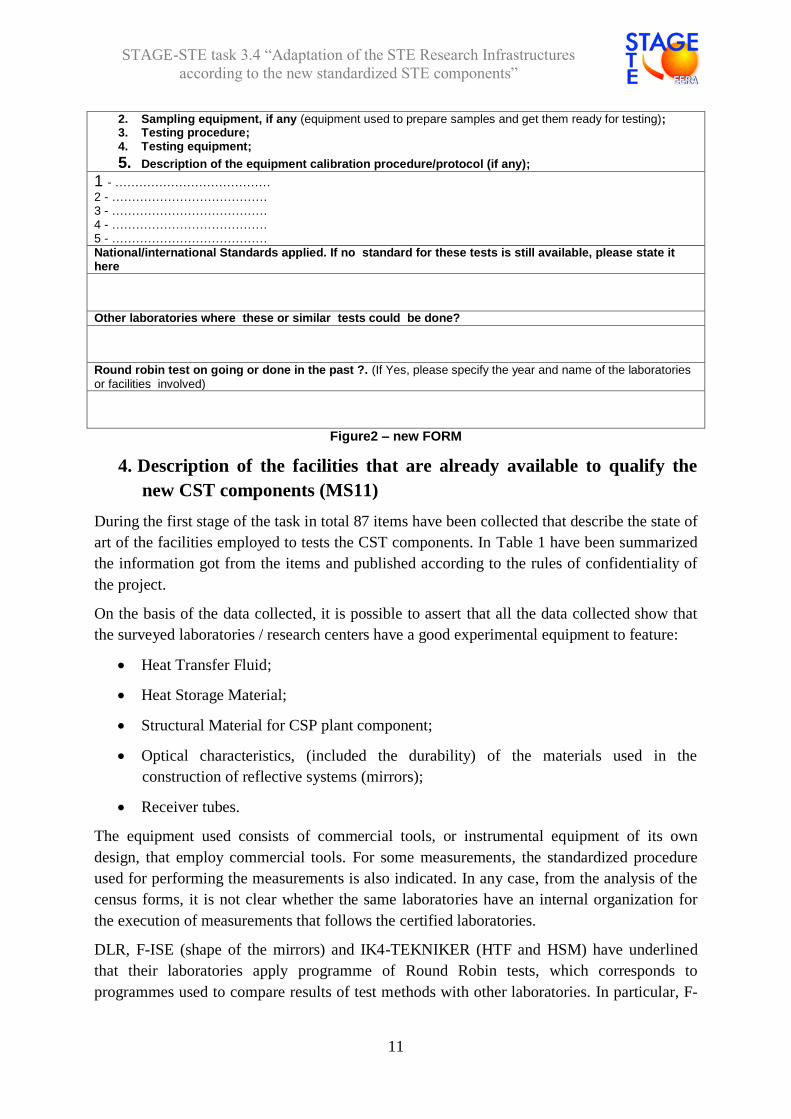
After this step, US and Ciemat/PSA have elaborated a new census Form (see Figure 2)
focused on aim to investigate on the characteristics of the procedures employed by the
selected test facilities to characterize the CST components and then to evaluate if these last
one have the qualities that usually are requested to the accredited test laboratories.
The census forms collected in the second stage have been collected in the annex II. On
analysis of these items it was elaborated an assessment of the current capacity of adaptation of
the qualification facilities of each research centre, according to the new standardized CST
components.
Description of Testing Protocols & Protocol requirements
1. Testing firming information (name of laboratory, responsible person/company);
STAGE-STE task 3.4 “Adaptation of the STE Research Infrastructures
according to the new standardized STE components”
11
2. Sampling equipment, if any (equipment used to prepare samples and get them ready for testing); 3. Testing procedure; 4. Testing equipment;
5. Description of the equipment calibration procedure/protocol (if any); 1 - …………………………………
2 - ………………………………… 3 - ………………………………… 4 - ………………………………… 5 - ………………………………… National/international Standards applied. If no standard for these tests is still available, please state it here
Other laboratories where these or similar tests could be done?
Round robin test on going or done in the past ?. (If Yes, please specify the year and name of the laboratories
or facilities involved)
Figure2 – new FORM
4. Description of the facilities that are already available to qualify the
new CST components (MS11)
During the first stage of the task in total 87 items have been collected that describe the state of
art of the facilities employed to tests the CST components. In Table 1 have been summarized
the information got from the items and published according to the rules of confidentiality of
the project.
On the basis of the data collected, it is possible to assert that all the data collected show that
the surveyed laboratories / research centers have a good experimental equipment to feature:
Heat Transfer Fluid;
Heat Storage Material;
Structural Material for CSP plant component;
Optical characteristics, (included the durability) of the materials used in the
construction of reflective systems (mirrors);
Receiver tubes.
The equipment used consists of commercial tools, or instrumental equipment of its own
design, that employ commercial tools. For some measurements, the standardized procedure
used for performing the measurements is also indicated. In any case, from the analysis of the
census forms, it is not clear whether the same laboratories have an internal organization for
the execution of measurements that follows the certified laboratories.
DLR, F-ISE (shape of the mirrors) and IK4-TEKNIKER (HTF and HSM) have underlined
that their laboratories apply programme of Round Robin tests, which corresponds to
programmes used to compare results of test methods with other laboratories. In particular, F-

STAGE-STE task 3.4 “Adaptation of the STE Research Infrastructures
according to the new standardized STE components”
12
ISE has inserted in a F-ISE programme the round robin tests within SolarPACES workgroups,
while IK4-TEKNIKER applies the standards set by the American Society for Testing and
Materials (ASTM) for the execution of the round robin tests.
Solar collectors at low/medium temperature (<300 °C)
With regard to the measurement of the performance of the solar collectors at low / medium
temperature, during the census, three accredited laboratories (approved laboratories follow the
dictates of the EN ISO 17025 / EN ISO / IEC 17025 / ISO-Guide 43-1) have been identified.
All laboratories follow the ISO 9806 standard. In particular:
- ENEA is able to test solar collectors to a temperature of up to 300 °C;
- FBK is able to test solar collectors to a temperature of up to 300°C;
- LNEG is able to test solar collectors to a temperature of up to 100°C;
- UEVORA indicates the presence of an accredited laboratory without giving
specifications in detail.
CIEMAT-PSA can also evaluate the performance of parabolic trough collectors at
low/medium temperatures. However, their facilities are not accredited for certification by ISO
standards.
The standard ISO 9806:2013 specifies test methods for assessing the durability, reliability and
safety for fluid heating collectors. It also includes test methods for the thermal performance
characterization of fluid heating collectors, namely steady-state and quasi-dynamic thermal
performance of glazed and unglazed liquid heating solar collectors and steady-state thermal
performance of glazed and unglazed air heating solar collectors (open to ambient as well as
closed loop) .
The theme of the collectors to medium / low temperature requires a greater deepening to
evaluate the potential of the market and the capacity to answer the requests of the industrial
sector. In particular it will be necessary to define survey methodology jointly with the
coordinator of WP5 (CEA - Commissariat à l'énergie atomique et aux énergies alternatives).
Solar collectors at high temperature (>300 °C)
ENEA is the only partner able to characterize the performance of outdoor parabolic solar
collectors that use molten salt as HTF. In this case, the qualification takes place according to
internal procedures.
PSA-CIEMAT is the only one able to supply facilities for the characterization of parabolic
solar collectors for high temperatures that use pressurized gases, steam or oil as HTF. PSA-
CIEMAT has a facility useful to characterize the Fresnel collectors (with water/steam as
HTF). For each kind of the characterization test, PSA-CIEMAT employs internal procedures.
FBK is able to test solar collectors at a small size reaching up to 350°C, using thermal oils as
HTF.
STAGE-STE task 3.4 “Adaptation of the STE Research Infrastructures
according to the new standardized STE components”
13
CTAER and DLR are able to test and evaluate the performance of Parabolic Trough
Module/Collector.
CST components for molten salt industrial loop
With regard to the ability to test components, only ENEA and PSA-CIEMAT have facilities
able to fulfill this task. Both partners employ not standardized procedures for the
characterization of components, but methodologies elaborated inside their laboratories.
Components for thermal energy storage system subservient to CST
Only ENEA has indicated the ability to characterize heat storage with molten salts and coil
steam generators.
Volumetric receiver
DLR and CIEMAT-PSA are the only ones able to provide facilities capable to test volumetric
receiver. For this activity they have nstalled own facilities.
Parabolic Trough Receiver
DLR and CIEMAT-PSA have different facilities to test the different features of parabolic
trough receivers. They are able to test both the optical and the thermal characteristics. Both
Partners can perform tests both in laboratory and in field. DLR facilities include also the
“Accelerated Ageing of Bellows” aspects. For the different measures, DLR and CIEMAT-
PSA use array of commercial instruments or own design facilities.
ENEA is able to test the thermal performance of parabolic trough receiver in laboratory by an
own facility.
Solar resource
DLR, CIEMAT-PSA and ENEA own some array of commercial instrumentation able to
measure the solar resource in the field.
- Definition of possible standard procedures for the characterization of CSP components
not yet existing;
- Identification of the families of CSP components where the practice of round robin
test is functional for the development of commonly recognized methods for their
characterization;
- Definition of the minimum characteristics that must have the laboratories to take part
at the programs of Round Robin tests;
Acceptance or less of existing standards for the implementation of round robin tests.

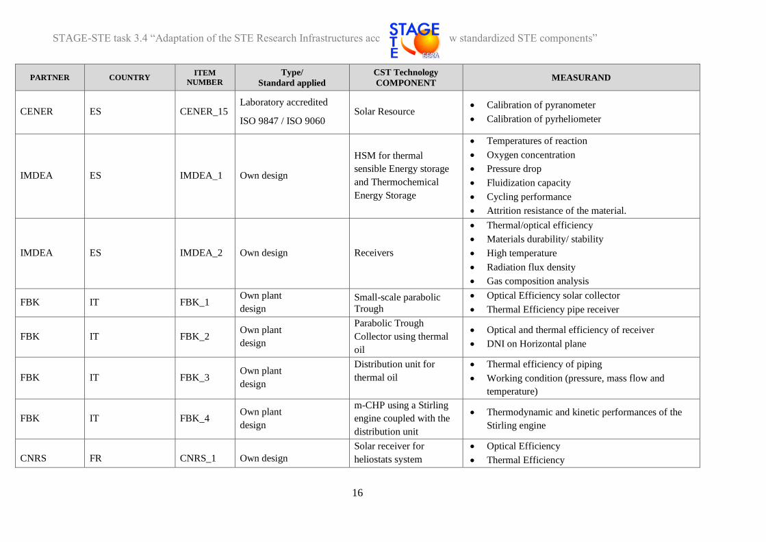
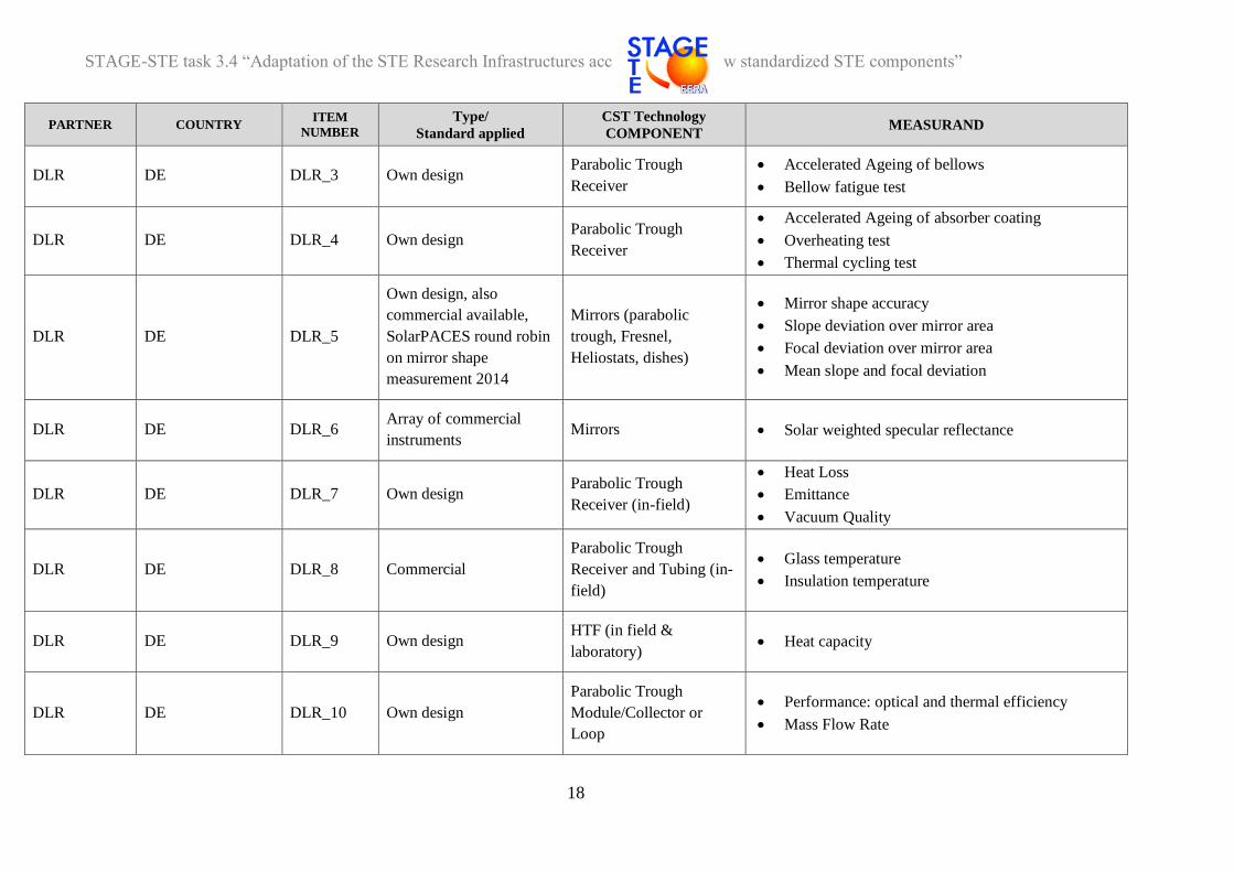
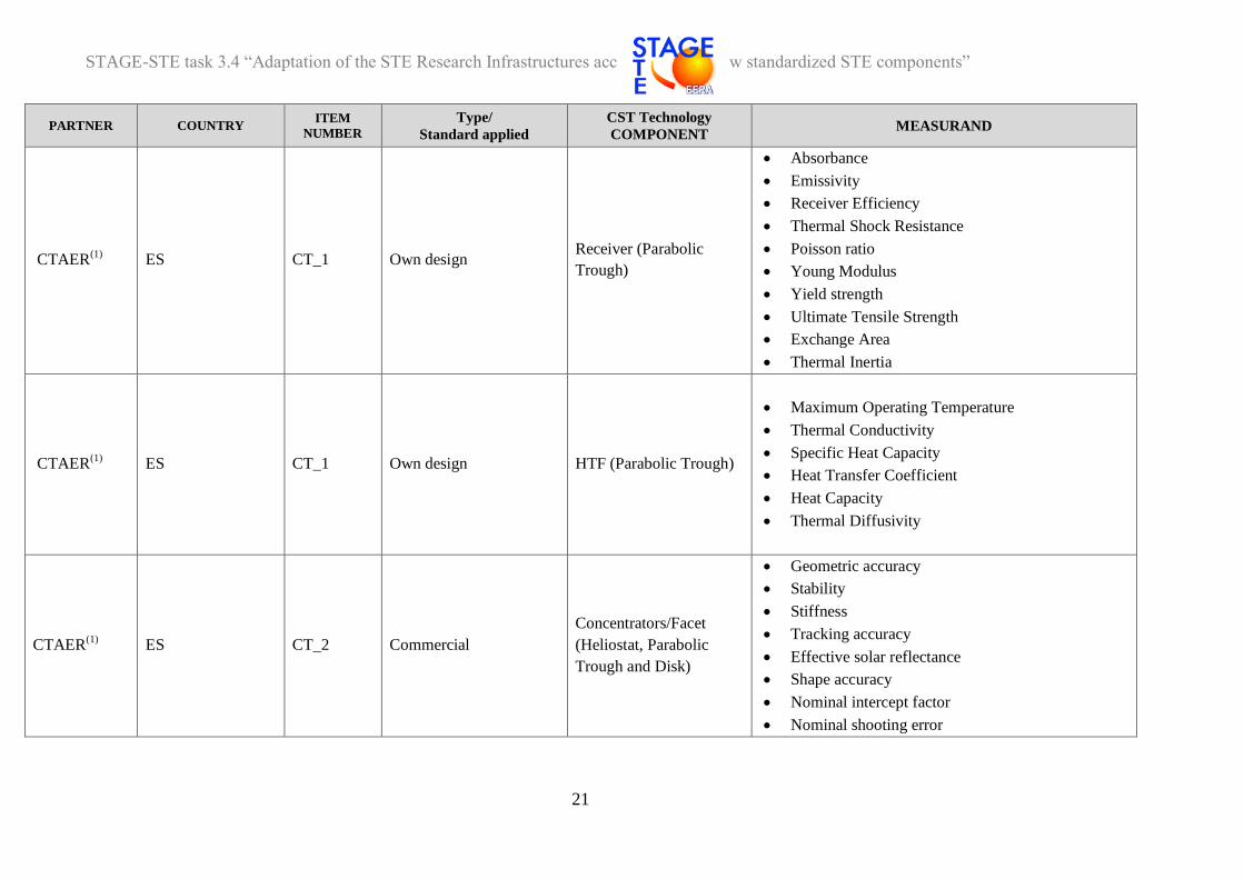
Table 1 – Collection of the items of description of the experimental facilities present at the partners of Task 3.4 . (MS11)
PARTNER COUNTRY ITEM
NUMBER
Type/
Standard applied
CST Technology
COMPONENT MEASURAND
CENER ES CENER_1 Own design Receiver tube On-site inspection of the surface temperature of
tubes
CENER ES CENER_2 Commercial Receiver tube
Indoor non-destructive optical characterization
Indoor qualification: thermal loss power of single
receiver tube
Indoor destructive optical characterization
(absorbance of the absorber tube and transmittance
of the glass tube)
CENER ES CENER_3 Commercial Mirrors Solar reflectance
Durability
CENER ES CENER_4 Commercial
Own design Mirror facet
Impact resistance test
Geometric characterization
CENER ES CENER_5 Own design Receiver material Thermal shocks
CENER ES CENER_6 Own design Parabolic Trough
On site characterization for:
Peak optical efficiency
Thermal losses
Incidence angle modifier
CENER ES CENER_7 Commercial instruments Central Receiver System,
Dish
On site high solar radiation flux
Surface temperature
CENER ES CENER_8 Commercial Solar Radiation
Measurement Station On-site measurement audit

STAGE-STE task 3.4 “Adaptation of the STE Research Infrastructures according to the new standardized STE components”
15
PARTNER COUNTRY ITEM
NUMBER
Type/
Standard applied
CST Technology
COMPONENT MEASURAND
CENER ES CENER_9 Own design Heliostat
Optical characterization
Geometry characterization
Tracking Accuracy
CENER ES CENER_10 Commercial HTF HTF Purity and traces analysis by GC/MS-FID
Chromatography
CENER ES CENER_11
Laboratory accredited
ISO 9806:2013/
EN 12975-1
Solar Thermal Collectors Thermal Performance
CENER ES CENER_12
Laboratory accredited
EN 12976-2/
ISO 9459-2 /
ISO 9459-5
Solar systems for the
production of sanitary
hot water
Thermal Performance
CENER ES CENER_13 Laboratory accredited
ISO EN 12977-3 Solar thermal store Thermal Performance
CENER ES CENER_14 Commercial Solar Resource
Measurement of DNI, GHI and DHI
Measurement of global horizontal downward
infrared irradiance with a pyrgeometer
Measurement of spectral direct normal irradiance
and spectral sky radiance with a sun photometer,
(part of the AERONET measurement network)
Wind speed and direction
STAGE-STE task 3.4 “Adaptation of the STE Research Infrastructures according to the new standardized STE components”
16
PARTNER COUNTRY ITEM
NUMBER
Type/
Standard applied
CST Technology
COMPONENT MEASURAND
CENER ES CENER_15 Laboratory accredited
ISO 9847 / ISO 9060 Solar Resource
Calibration of pyranometer
Calibration of pyrheliometer
IMDEA ES IMDEA_1 Own design
HSM for thermal
sensible Energy storage
and Thermochemical
Energy Storage
Temperatures of reaction
Oxygen concentration
Pressure drop
Fluidization capacity
Cycling performance
Attrition resistance of the material.
IMDEA ES IMDEA_2 Own design Receivers
Thermal/optical efficiency
Materials durability/ stability
High temperature
Radiation flux density
Gas composition analysis
FBK IT FBK_1 Own plant
design
Small-scale parabolic
Trough
Optical Efficiency solar collector
Thermal Efficiency pipe receiver
FBK IT FBK_2 Own plant
design
Parabolic Trough
Collector using thermal
oil
Optical and thermal efficiency of receiver
DNI on Horizontal plane
FBK IT FBK_3 Own plant
design
Distribution unit for
thermal oil
Thermal efficiency of piping
Working condition (pressure, mass flow and
temperature)
FBK IT FBK_4 Own plant
design
m-CHP using a Stirling
engine coupled with the
distribution unit
Thermodynamic and kinetic performances of the
Stirling engine
CNRS FR CNRS_1 Own design
Solar receiver for
heliostats system
Optical Efficiency
Thermal Efficiency

STAGE-STE task 3.4 “Adaptation of the STE Research Infrastructures according to the new standardized STE components”
17
PARTNER COUNTRY ITEM
NUMBER
Type/
Standard applied
CST Technology
COMPONENT MEASURAND
TECNALIA ES TEC_1 Commercial HTF, HSM
Melting point
Heat Capacity
Enthalpy
IK4-
TEKNIKER ES TKN_1 Commercial HTF Composition thermal oil
IK4-
TEKNIKER ES TKN_2 Commercial HTF
Physical properties of thermal oil
Chemical properties of thermal oil
IK4-
TEKNIKER ES TKN_
Commercial/Standard
ASTM D 6743 HTF
Heat transfer fluids thermal oil
Thermal stability thermal oil
IK4-
TEKNIKER ES TKN_4 Commercial HSM Composition MS
IK4-
TEKNIKER ES TKN_5
Commercial/
ASTMD 3417
ASTMD 3418
ASTM E1269
HSM Thermal properties MS
F- ISE DE FISE_1
Commercial /
SolarPACES round robin
on mirror shape
measurement 2014.
Mirrors (parabolic
trough, Fresnel,
Heliostats, dishes)
Mirror shape
Gradient distribution of mirror area
Curvature over mirror area
Derived parameters
DLR DE DLR_1 Own design Parabolic Trough
Receiver Thermal Loss Power / Thermal performance
DLR DE DLR_2 Own design Parabolic Trough
Receiver Optical Efficiency (relative to reference receiver)
STAGE-STE task 3.4 “Adaptation of the STE Research Infrastructures according to the new standardized STE components”
18
PARTNER COUNTRY ITEM
NUMBER
Type/
Standard applied
CST Technology
COMPONENT MEASURAND
DLR DE DLR_3 Own design Parabolic Trough
Receiver
Accelerated Ageing of bellows
Bellow fatigue test
DLR DE DLR_4 Own design Parabolic Trough
Receiver
Accelerated Ageing of absorber coating
Overheating test
Thermal cycling test
DLR DE DLR_5
Own design, also
commercial available,
SolarPACES round robin
on mirror shape
measurement 2014
Mirrors (parabolic
trough, Fresnel,
Heliostats, dishes)
Mirror shape accuracy
Slope deviation over mirror area
Focal deviation over mirror area
Mean slope and focal deviation
DLR DE DLR_6 Array of commercial
instruments Mirrors Solar weighted specular reflectance
DLR DE DLR_7 Own design Parabolic Trough
Receiver (in-field)
Heat Loss
Emittance
Vacuum Quality
DLR DE DLR_8 Commercial
Parabolic Trough
Receiver and Tubing (in-
field)
Glass temperature
Insulation temperature
DLR DE DLR_9 Own design HTF (in field &
laboratory) Heat capacity
DLR DE DLR_10 Own design
Parabolic Trough
Module/Collector or
Loop
Performance: optical and thermal efficiency
Mass Flow Rate

STAGE-STE task 3.4 “Adaptation of the STE Research Infrastructures according to the new standardized STE components”
19
PARTNER COUNTRY ITEM
NUMBER
Type/
Standard applied
CST Technology
COMPONENT MEASURAND
DLR DE DLR_11 Own design Central Receiver System,
Dish
Solar Flux Density Measurement
Solar Input Power
DLR DE DLR_12 Own design, Commercial Central Receiver, Dish
Receiver Optical efficiency of receiver
DLR DE DLR_13 Own design, Commercial Heliostat
Tracking Accuracy
Shape
Gravitational shape Deformation
DLR/PSA DE DLR_14
(PSA_4) Own design Volumetric receivers
Thermal performance
Ageing
DLR/PSA DE DLR_15
(PSA_5) Own design Dish Receivers Thermal accelerated ageing of raw materials
DLR/PSA DE DLR_16
(PSA_11)
Array of commercial
instruments Concentrator, reflectors
Optical Characterization
Durability
DLR/PSA DE DLR_17
(PSA_12)
Array of commercial
instruments Mirror facets
Optical quality of concentrators
Durability
Solar reflectance

STAGE-STE task 3.4 “Adaptation of the STE Research Infrastructures according to the new standardized STE components”
20
PARTNER COUNTRY ITEM
NUMBER
Type/
Standard applied
CST Technology
COMPONENT MEASURAND
DLR DE DLR_18 Own design, Commercial Solar Resource
Measurement of DNI, GHI and DHI with both
thermal sensors and RSIs
Measurement of global horizontal downward
infrared irradiance with a pyrometer
Measurement of spectral direct normal irradiance
and spectral sky radiance with a sun photometer,
which is part of the AERONET measurement
network
Wind speed and direction at 10m
Temperature and humidity profile at 2 m
Barometer
Visibility
SAM
Ceilometer
Lidar
All sky cameras
Shadow-cameras
STAGE-STE task 3.4 “Adaptation of the STE Research Infrastructures according to the new standardized STE components”
21
PARTNER COUNTRY ITEM
NUMBER
Type/
Standard applied
CST Technology
COMPONENT MEASURAND
CTAER(1)
ES CT_1 Own design Receiver (Parabolic
Trough)
Absorbance
Emissivity
Receiver Efficiency
Thermal Shock Resistance
Poisson ratio
Young Modulus
Yield strength
Ultimate Tensile Strength
Exchange Area
Thermal Inertia
CTAER(1)
ES CT_1 Own design HTF (Parabolic Trough)
Maximum Operating Temperature
Thermal Conductivity
Specific Heat Capacity
Heat Transfer Coefficient
Heat Capacity
Thermal Diffusivity
CTAER(1)
ES CT_2 Commercial
Concentrators/Facet
(Heliostat, Parabolic
Trough and Disk)
Geometric accuracy
Stability
Stiffness
Tracking accuracy
Effective solar reflectance
Shape accuracy
Nominal intercept factor
Nominal shooting error

STAGE-STE task 3.4 “Adaptation of the STE Research Infrastructures according to the new standardized STE components”
22
PARTNER COUNTRY ITEM
NUMBER
Type/
Standard applied
CST Technology
COMPONENT MEASURAND
CTAER(1)
ES CT_3 Own design Central Receivers
Absorbance, Receiver Efficiency
Thermal Inertia
Maximum Operating Temperature
Thermal Shock
Thermal Conductivity
Poisson ratio
Young Modulus
Yield strength
Ultimate Tensile Strength
Absorbance
Reflectance
Emissivity
Heat Transfer Coefficient
Exchange Area
UEVORA PT UEVO_1
Own design /
Application ISO9806
procedures
Line-focus concentrator
modules based on
different technological
concepts
Optical characterization parameters of line-focus
concentrators
Thermal characterization parameters of line-focus
concentrators
UEVORA PT UEVO_2
Own design /
Application ISO9806
procedures
Parabolic Trough Loop
using Molten Salts Instantaneous efficiency
UNIPA IT EN PA_1 Own design Solar fuel chemical
reactor
Experimental plant under construction to evaluate
the characteristics of chemical reactor for solar fuel
CYI CY CYI_1 Own design Heliostat-receiver Little tower solar experimental plant under
construction

STAGE-STE task 3.4 “Adaptation of the STE Research Infrastructures according to the new standardized STE components”
23
PARTNER COUNTRY ITEM
NUMBER
Type/
Standard applied
CST Technology
COMPONENT MEASURAND
ENEA IT EN_1 Commercial HTF/HSM
Phase diagrams
Phase change heats
Heat capacity
ENEA IT EN_2 Own design HTF/HSM Thermal stability
ENEA IT EN_3 Commercial HTF/HSM Viscosity
ENEA IT EN_4 Commercial HTF/HSM Decomposition of molten salts mixtures
ENEA IT EN_5 Commercial Mirrors Point coordinates of the position in space (x,y,z)
ENEA IT EN_6 Own design Mirrors Near-specular reflectance
ENEA IT EN_7 Own design Mirrors facet Optical quality of concentrators
ENEA IT EN_8 Own design Parabolic trough
collectors Intercept factor map
ENEA IT EN_9 Own design Mirrors Shape
ENEA IT EN_10 Own design Receiver pipes Indoor qualification: thermal loss power of a single
receiver tube
ENEA IT EN_11 Own design
Parabolic-trough
collectors (PTC) with
molten salt as HTF (Up
to 530°C)
Thermal Efficiency in real condition
Optimization of the operating procedures with
molten salt
ENEA IT EN_11 Own design Pipe receiver with molten
salt as HTF fluid Thermal Efficiency in real condition

STAGE-STE task 3.4 “Adaptation of the STE Research Infrastructures according to the new standardized STE components”
24
PARTNER COUNTRY ITEM
NUMBER
Type/
Standard applied
CST Technology
COMPONENT MEASURAND
ENEA IT EN_11 Own design
Molten salt components
Durability
Thermal loss
Temperature profile
Drop pressure, with flow of MS
Optimization of the operating procedures with
molten salt
ENEA IT EN_11 Own design
Thermal storage with
molten salt as HSM
Thermal loss, temperature
Thermal stratification
Optimization of the operating procedures with
molten salt
ENEA IT EN_11 Own design
Coil SG for MS
Temperature
Pressure
Global heat exchange coefficients
ENEA IT EN_12 Own design
Material Dynamic corrosion
ENEA IT EN_13
Laboratory accredited
ISO 9806:2013
EN 12975-2
Solar Thermal Collectors
(up to 300 ºC) Thermal Performance
ENEA IT EN_14
Laboratory accredited
ISO EN 12976-2
ISO 9459-2
Solar systems for the
production of sanitary
hot water
Thermal Performance

STAGE-STE task 3.4 “Adaptation of the STE Research Infrastructures according to the new standardized STE components”
25
PARTNER COUNTRY ITEM
NUMBER
Type/
Standard applied
CST Technology
COMPONENT MEASURAND
ENEA IT EN_14 Own design, Commercial Solar Resource
Measurement of DNI, GHI and DHI with both
thermal sensors and RSIs
Measurement of global horizontal downward
infrared irradiance with a pyrometer
Measurement of spectral direct normal irradiance
and spectral sky radiance with a sun photometer
Wind speed and direction at 10m
Temperature and humidity profile at 2 m
Barometer
LNEG PT LNEG_1
Own design/
Laboratory accredited
ISO 9806:2013
Solar Thermal Collectors
(up to 100 ºC) Thermal Performance
LNEG PT LNEG_2 Commercial Not applied DNI
LNEG PT LNEG_3 Commercial Mirrors Reflectance spectrum in the solar spectrum (250-
2500 nm)
LNEG PT LNEG_4 Certified laboratory Bio fuel
Chemical characterization of biomass
Thermo physical complete characterization of
biomass
LNEG PT LNEG_5 Array commercial
instrument
Mirrors
Material for CSP plant Durability of Materials
LNEG PT LNEG_6 Array commercial
instrument bio fuel Syngas and tars chemical composition

STAGE-STE task 3.4 “Adaptation of the STE Research Infrastructures according to the new standardized STE components”
26
PARTNER COUNTRY ITEM
NUMBER
Type/
Standard applied
CST Technology
COMPONENT MEASURAND
CIEMAT/PSA ES PSA_1 Commercial
instrumentations Linear Receiver
Solar absorptance
Thermal emittance
Solar transmittance
Surface contact angle
Accelerated aging
Abrasion resistance
CIEMAT/PSA ES PSA_2 Own design Solar reactors for Central
Receiver systems
Solar reactors performance in real operating
condition
CIEMAT/PSA ES PSA_3 Own design Materials for thermo
chemical water splitting Cycling performance
CIEMAT/PSA ES PSA_4 Own design Volumetric receivers Thermal performance
Ageing
CIEMAT/PSA ES PSA_5 Own design Dish Receivers Thermal accelerated ageing of raw materials
CIEMAT/PSA ES PSA_6 Own design
Small parabolic-trough
collectors with water as
HTF
Efficiency in real operating conditions
Peak optical-geometrical efficiency
CIEMAT/PSA ES PSA_7 Array of commercial
instruments
Materials for CSP
components
Hardness
Rugosity
Uniformity and surface finish
Depth of treated surface of materials
Characterization of materials in clean room
temperature to 1750 ºC in different atmospheres

STAGE-STE task 3.4 “Adaptation of the STE Research Infrastructures according to the new standardized STE components”
27
PARTNER COUNTRY ITEM
NUMBER
Type/
Standard applied
CST Technology
COMPONENT MEASURAND
CIEMAT/PSA ES PSA_8 Own design
Any component for
parabolic trough solar
fields with Direct Steam
Generation
Cycling performance
Thermo-hydraulic performance of two-phase of
water/steam in horizontal line with non-
homogeneous heat flux
Performance for parabolic-trough collector solar
fields with direct steam
Performance for line-focus collector solar fields
with direct steam
Ageing components with direct steam
optimization of the operating procedures with
direct steam
CIEMAT/PSA ES PSA_9 Own design Molten salt components
Durability
Thermal loss
Ageing in real operative condition
Temperature profile
Drop pressure, with flow of MS
CIEMAT/PSA ES PSA_10 Own
design Molten salt components
Durability
Thermal loss
Ageing in real operative condition
Temperature profile
Drop pressure, with flow of MS
Optimization of the operating procedures with
molten salt
CIEMAT/PSA ES PSA_11 Array of commercial
instruments Concentrator, reflectors
Optical Characterization
Durability
STAGE-STE task 3.4 “Adaptation of the STE Research Infrastructures according to the new standardized STE components”
28
PARTNER COUNTRY ITEM
NUMBER
Type/
Standard applied
CST Technology
COMPONENT MEASURAND
CIEMAT/PSA ES PSA_12 Array of commercial
instruments Mirror facets
Optical quality of concentrators
Durability
Solar reflectance
CIEMAT/PSA ES PSA_13 Array of commercial
instruments Solar receivers
High solar radiation flux
Surface temperature.
CIEMAT/PSA ES PSA_14 Own design Solar Furnaces
Temperature and thermal flux distribution on
absorbers and tested samples
Temperature and flow of air in volumetric receivers
Temperature and flow of gas produced in solar
reactors
Temperature of materials processed in reactors
CIEMAT/PSA ES CIEMAT_1 Laboratory with
commercial equipment
Structural Material for
CST plant component
Corrosion static test
Microscopy surface characterization material
Mechanical characterization of structural alloys
CIEMAT/PSA ES PSA_16 Own design
Linear Fresnel modules,
mirrors and receivers for
linear Fresnel collectors
Optical efficiency (including incidence angle
modifier).
Ageing components with direct steam
optimization of the operating
CIEMAT/PSA ES PSA_17 Own design
Large parabolic-trough
collectors (PTC) and
receiver pipes with Oil as
HTF (Up to 400 °C)
Peak optical efficiency
Incidence angle modifier.
Heat losses
CIEMAT/PSA ES PSA_18 Own design
Parabolic-trough
collectors (PTC),
receiver tubes with
pressurized gas as HTF
Performance for parabolic-trough collector solar
fields using compressed gas as HTF
Ageing components using compressed gas as HTF
Pressure losses in solar receivers using compressed
gas as HTF

STAGE-STE task 3.4 “Adaptation of the STE Research Infrastructures according to the new standardized STE components”
29
PARTNER COUNTRY ITEM
NUMBER
Type/
Standard applied
CST Technology
COMPONENT MEASURAND
CIEMAT/PSA ES PSA_19 Own design Receiver pipes
Outdoor qualification of optical performance
Indoor qualification of thermal loss power of single
receiver tubes
CIEMAT/PSA ES PSA_20 Own design
Linear Fresnel collector
(LFC) modules and
receiver tubes for LFC
Outdoor qualification of Optical efficiency
(including incidence angle modifier)
Heat losses.
(1) : the CTAER facilities are not available right now
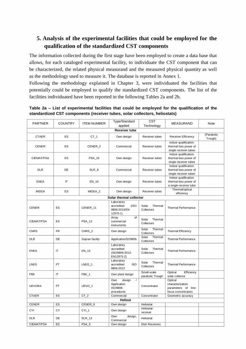
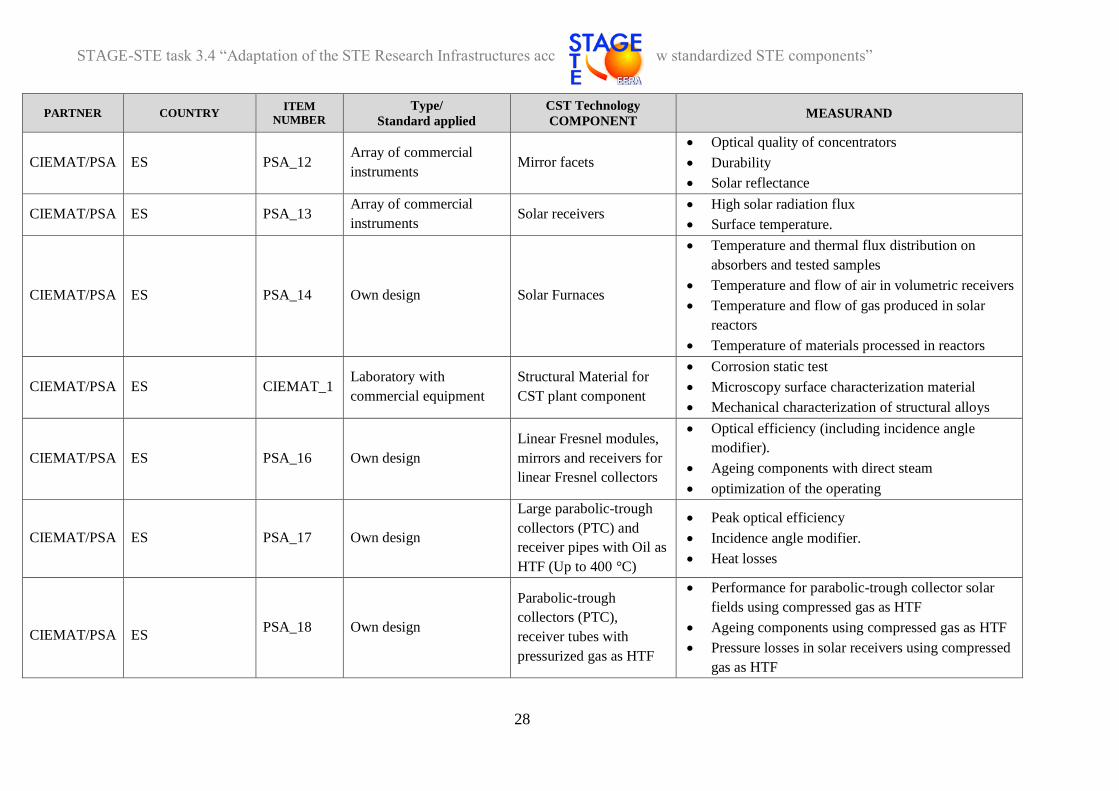
5. Analysis of the experimental facilities that could be employed for the
qualification of the standardized CST components
The information collected during the first stage have been employed to create a data base that
allows, for each cataloged experimental facility, to individuate the CST component that can
be characterized, the related physical measurand and the measured physical quantity as well
as the methodology used to measure it. The database is reported in Annex 1.
Following the methodology explained in Chapter 3, were individuated the facilities that
potentially could be employed to qualify the standardized CST components. The list of the
facilities individuated have been reported in the following Tables 2a and 2b.
Table 2a – List of experimental facilities that could be employed for the qualification of the
standardized CST components (receiver tubes, solar collectors, heliostats)
PARTNER COUNTRY ITEM NUMBER Type/Standard
applied
CST
Technology MEASURAND Note
Receiver tube
CTAER ES CT_1 Own design Receiver tubes Receiver Efficiency(Parabolic
Trough)
CENER ES CENER_2 Commercial Receiver tubes
Indoor qualification:
thermal loss power of
single receiver tubes
CIEMAT/PSA ES PSA_19 Own design Receiver tubes
Indoor qualification:
thermal loss power of
single receiver tubes
DLR DE DLR_8 Commercial Receiver tubes
Indoor qualification:
thermal loss power of
single receiver tubes
ENEA IT EN_10 Own design Receiver tubes
Indoor qualification:
thermal loss power of
a single receiver tube
IMDEA ES IMDEA_2 Own design Receiver tubes Thermal/optical
efficiency
Solar thermal collector
CENER ES CENER_11
Laboratory
accredited (ISO
9806:2013/EN
12975-1)
Solar Thermal
Collectors Thermal Performance
CIEMAT/PSA ES PSA_13
Array of
commercial
instruments
Solar Thermal
Collectors
CNRS FR CNRS_2 Own design Solar Thermal
Collectors Thermal Efficiency
DLR DE Sopran facility ApplicationISO9806 Solar Thermal
Collectors Thermal Performance
ENEA IT EN_13
Laboratory
accredited
(ISO9806:2013-
EN12975-2)
Solar Thermal
Collectors Thermal Performance
LNEG PT LNEG_1
Laboratory
accredited ISO
9806:2013
Solar Thermal
Collectors Thermal Performance
FBK IT FBK_1 Own plant design Small-scale
parabolic Trough
Optical Efficiency
solar collector
UEVORA PT UEVO_1
Own design /
Application
ISO9806
procedures
Concentrator
Optical
characterization
parameters of line-
focus concentrators
CTAER ES CT_2 Commercial Concentrator Geometric accuracy
Heliost
CENER ES CENER_9 Own design Heliostat
CYI CY CYI_1 Own design Heliostat-
receiver
DLR DE DLR_13 Own design,
Commercial Heliostat
CIEMAT/PSA ES PSA_5 Own design Dish Receivers

STAGE-STE task 3.4 “Adaptation of the STE Research Infrastructures
according to the new standardized STE components”
31
Table 2b – List of experimental facilities that could be employed for the qualification of the
standardized CST components (mirrors, reflectors)
PARTNER COUNTRY ITEM NUMBER Type/Standard
applied
CST
Technology MEASURAND Note
Mirrors
CENER ES CENER_3 Commercial Mirrors Solar reflectance
CENER ES CENER_3 Commercial Mirrors Durability
CENER ES CENER_4 Commercial/Own
design Mirrors Impact resistance test facet
CENER ES CENER_4 Commercial/Own
design Mirrors
Geometric
characterizationfacet
CIEMAT/PSA ES PSA_12
Array of
commercial
instruments
Mirrors Optical quality of
concentratorsfacet
CIEMAT/PSA ES PSA_16 Own design Mirrors
Optical efficiency
(including incidence
angle modifier)
for linear
Fresnel
collectors
CIEMAT/PSA ES PSA_11
Array of
commercial
instruments
Reflectors Optical
Characterization
DLR DE DLR_6
Array of
commercial
instruments
Mirrors Solar weighted
specular reflectance
DLR DE DLR_5
Own design, also
commercial
available,
SolarPACES round
robin on mirror
shape
measurement 2014
Mirrors Mirror shape accuracy
(parabolic
trough, Fresnel,
Heliostats,
dishes)
DLR/PSA DE DLR_17/PSA_12
Array of
commercial
instruments
Mirrors Optical quality of
concentrators facet
DLR/PSA DE DLR_16/PSA_11
Array of
commercial
instruments
Reflectors Optical
Characterization
ENEA IT EN_9 Own design Mirrors Shape
ENEA IT EN_7 Own design Mirrors Optical quality of
concentratorsfacet
F- ISE DE FISE_1
Commercial /
SolarPACES round
robin on mirror
shape
measurement
2014.
Mirrors Mirror shape
(parabolic
trough, Fresnel,
Heliostats,
dishes)
LNEG PT LNEG_3 Commercial Mirrors
Reflectance spectrum
in the solar spectrum
(250-2500 nm).
LNEG PT LNEG_5 Array commercial
instrument Mirrors Durability of Materials

STAGE-STE task 3.4 “Adaptation of the STE Research Infrastructures
according to the new standardized STE components”
32
6. Assessment of the current capacity of adaptation of the qualification
facilities of each research centre, according to the new standardized
CST components
In Annex 2 have been reported the 41 items collected to estimate the capacities and the needs
for the adaptation of the existing experimental facilities to be employed as station of
qualification of the main CST components (Receiver tubes, Parabolic trough collectors,
Heliostats and Mirrors), according to the new standards currently being developed. In Annex
2 the items have been divided for CST components.
In technical or industrial use, the standards for the measurement are a set of rules designed to
homogenise the procedures employed to qualify the characteristics of a standard industrial
product. The process of definition of the standards is strictly connected with the different
phases of the development of the technology.
These phases are characterized by an intense competition for the affirmation of the
technological solution preferred by the market. The evolution of the processes can be
decomposed into three distinct stages: an uncoordinated stage, a segmented stage and a
systemic stage.
In the first stage of the technology development cycle, the process is flexible and is based on a
series of mostly non-specific processes. The goal is to prepare to respond to a rapidly
expanding market, in which precise trends have not yet emerged, thus making it necessary to
structure the process to facilitate the rapid introduction of reducing the risk of technological
obsolescence linked to uncertainty in the definition of industrial standards.
At this stage, the process innovation is less critical and is still characterized by the scanning of
different technical choices to be evaluated in perspective with respect to the potential for
expansion in successive stages.
In the subsequent stages, it follows the market assertion of a dominant design that defines the
combination of product technology and winning process, in terms of share and variety of
segments covered. The fundamental criticality in terms of innovation becomes the ability to
identify stable solutions on the production side, through the optimization of the process both
in its individual phases and in overall coordination. This involves developing or adopting
innovative technologies that shift emphasis from cycle flexibility to standardization.
In the case of CST components for linear receivers, in consideration of the existing plants, it
is possible to tell that we passed the first stage.
For the items relative to the qualification of indoor tests for the measure of the thermal losses
and the optical performance of receiver tubes, up to now some laboratories, in cooperation
among them, apply the same procedures and are involved in programs of round robin tests.
Round robin tests or proficiency tests are an essential element of quality assurance for
laboratories. The objective of proficiency tests is to ensure the quality and comparability of
measurement results by the laboratories. Comparability is no longer guaranteed if the
laboratories get very different results in the analysis of identical samples. To prevent such a
STAGE-STE task 3.4 “Adaptation of the STE Research Infrastructures
according to the new standardized STE components”
33
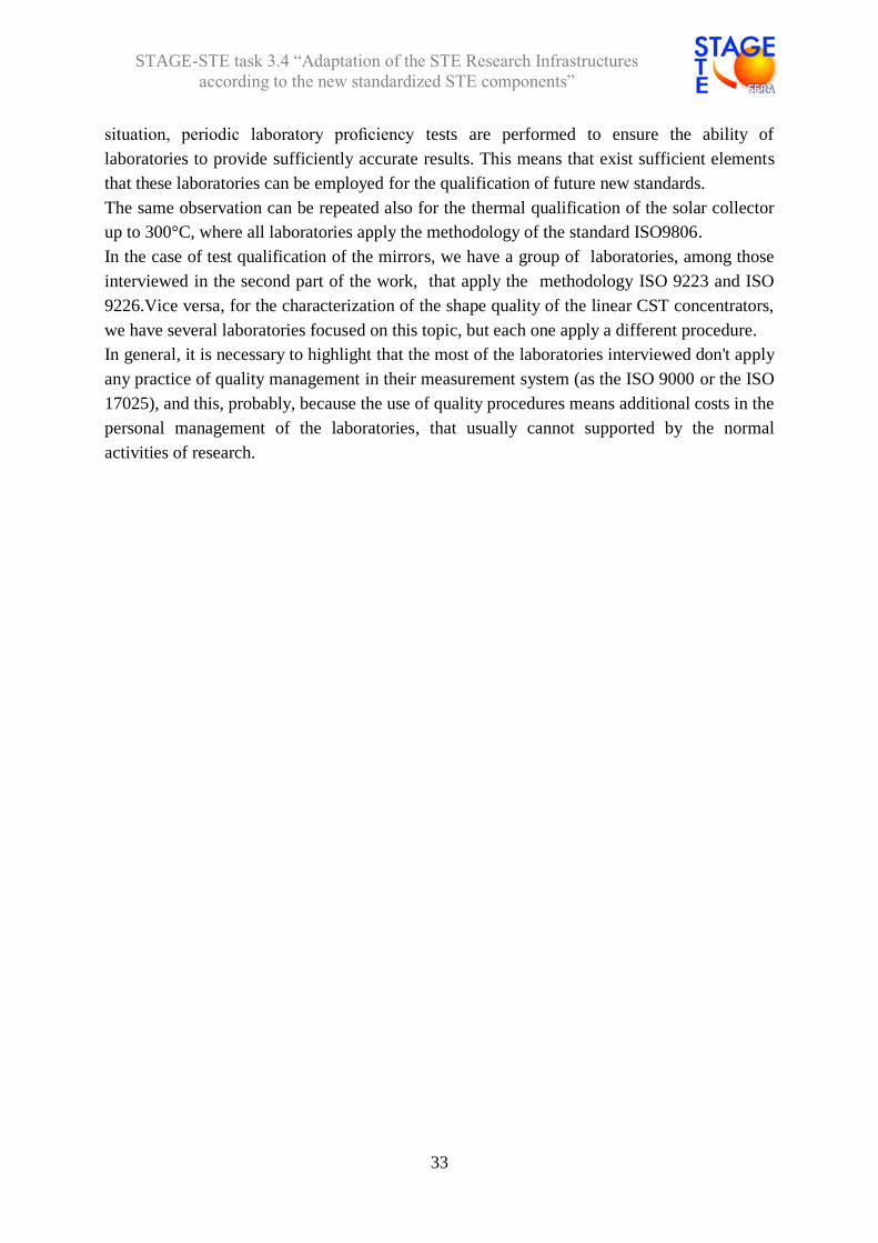
situation, periodic laboratory proficiency tests are performed to ensure the ability of
laboratories to provide sufficiently accurate results. This means that exist sufficient elements
that these laboratories can be employed for the qualification of future new standards.
The same observation can be repeated also for the thermal qualification of the solar collector
up to 300°C, where all laboratories apply the methodology of the standard ISO9806.
In the case of test qualification of the mirrors, we have a group of laboratories, among those
interviewed in the second part of the work, that apply the methodology ISO 9223 and ISO
9226.Vice versa, for the characterization of the shape quality of the linear CST concentrators,
we have several laboratories focused on this topic, but each one apply a different procedure.
In general, it is necessary to highlight that the most of the laboratories interviewed don't apply
any practice of quality management in their measurement system (as the ISO 9000 or the ISO
17025), and this, probably, because the use of quality procedures means additional costs in the
personal management of the laboratories, that usually cannot supported by the normal
activities of research.
STAGE-STE task 3.4 “Adaptation of the STE Research Infrastructures
according to the new standardized STE components”
34
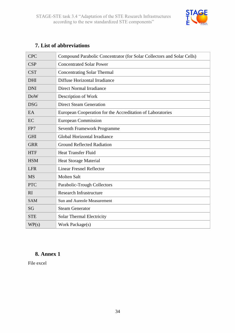
7. List of abbreviations
CPC Compound Parabolic Concentrator (for Solar Collectors and Solar Cells)
CSP Concentrated Solar Power
CST Concentrating Solar Thermal
DHI Diffuse Horizontal Irradiance
DNI Direct Normal Irradiance
DoW Description of Work
DSG Direct Steam Generation
EA European Cooperation for the Accreditation of Laboratories
EC European Commission
FP7 Seventh Framework Programme
GHI Global Horizontal Irradiance
GRR Ground Reflected Radiation
HTF Heat Transfer Fluid
HSM Heat Storage Material
LFR Linear Fresnel Reflector
MS Molten Salt
PTC Parabolic-Trough Collectors
RI Research Infrastructure
SAM Sun and Aureole Measurement
SG Steam Generator
STE Solar Thermal Electricity
WP(s) Work Package(s)
8. Annex 1
File excel

STAGE-STE task 3.4 “Adaptation of the STE Research Infrastructures
according to the new standardized STE components”
35
9. Annex 2
Receiver tubes
1-CENER – indoor tests (optical and thermal loss)
Description of Testing Protocols & Protocol requirements
1. Testing firming information (name of laboratory, responsible person/company);
2. Sampling equipment, if any (equipment used to prepare samples and get them ready for testing);
3. Testing procedure;
4. Testing equipment;
5. Description of the equipment calibration procedure/protocol (if any);
Description of Testing Protocols & Protocol requirements
Test objective (parameter to be evaluated/analysed):
Solar Receiver tube testing benches
1. Testing firming information (name of laboratory, responsible person/company);
CENER, Alberto García de Jalón, Head of Measurement & Characterization unit
2. Sampling equipment, if any (equipment used to prepare samples and get them ready for testing): N/A
3. Testing procedure:
Optical Characterization of Solar Receiver Tubes:
Optical characterization consists of taking spectral measurement of the transmittance of the outer glass cover and the
reflectivity of the metal absorber tube in 10 positions along the PTC receiver tube in order to analyse the uniformity of
optical properties of receiver tubes tested at ambient temperature. The solar S-tube receiver optical characterization testbed
determines the optical properties of a PTC receiver tube by non-destructive testing. The testbed can make simultaneous
spectral measurements of specular transmittance () and reflectance () in a range wavelength range () of 300 nm to
2500 nm in measurement stages of up to = 10 nm. Finally, the solar absorbance (s) and solar transmittance (ts) are
calculated by integrating over the spectral distribution of the direct solar radiation to air mass AM1.5.
Thermal Characterization of Solar Receiver tubes:
This type of characterization consists in determining the thermal characterization of receiver tubes. This consists of
calculating the characteristic thermal loss curve per unit of length of a PTC receiver tube at different temperatures from 100
to 500ºC. The testbed is made up of two heating elements which enable the interior of the PTC receiver tube to be heated by
radiation to generate temperature ranges similar to those under operating conditions. The electrical power supplied to the
group of elements inside the PTC receiver tube is measured when the temperature of the absorber tube has reached steady-
state, and is therefore equivalent to thermal loss in the PTC receiver tube at operating temperature. Receiver tube emittance
is determined based on the thermal loss measured at the selected operating temperature.
4. Testing equipment:
- Testbed for optical characterization of solar receivers tubes in parabolic-trough collectors - Testbed for thermal characterization of solar receivers tubes in parabolic-trough collectors
5. Description of the equipment calibration procedure/protocol (if any):
Optical: Glass reference for transmittance measurements and Chrome calibrated reference for reflectance measurements.
Thermal Losses: Calibration of the most critical sensors (thermocouples, power traducers)
A) National/international Standards applied for this Test. If no standard for these tests is still available, please state it here
There are not standards in force. Spectral distribution at air mass AM1.5 based on the solar spectrum of the Standard ASTM G173 or
ISO 9845-1.Drafts standards under AENOR committee.
B) Other laboratories where these or similar tests could be done?
F-ISE, DLR,PSA,ENEA
C) Round robin test on going or done in the past ?(If Yes, please specify the year and name of the laboratories or facilities involved)
2014-2015: STAGE-STE, optical & thermal characterization for solar receiver tubes

STAGE-STE task 3.4 “Adaptation of the STE Research Infrastructures
according to the new standardized STE components”
36
2-CIEMAT/PSA – indoor tests (thermal loss) and outdoor tests (optical)
Description of Testing Protocols & Protocol requirements
1. Testing firming information (name of laboratory, responsible person/company); 2. Sampling equipment, if any (equipment used to prepare samples and get them ready for testing); 3. Testing procedure; 4. Testing equipment; 5. Description of the equipment calibration procedure/protocol (if any);
1 –Laboratory of optical and thermal qualification of receiver tubes (RESOL&HEATREC test benches),Loreto Valenzuela/CIEMAT
2 –No sampling equipment is required
3–RESOL: Method suggested by Kutscher et al. (Kutscher, C.F. and Netter, J. (2014), Journal of Solar Energy Engineering, 136, 010907-1/5.). A transient method for measuring the optical efficiency of evacuated receivers.
HEATREC: Heat loss equals the electric power consumption at steady state conditions. Test method initially suggested by Burkholder and Kutscher, NREL/TP-550-42394 (2008). HEATREC test bench allows the measurement of heat losses in an evacuated atmosphere.
4–The laboratory has two main test benches for testing and measuring the performance of receiver tubes designed for
parabolic-trough collectors:
RESOL (outdoor qualification): Test bench for determining the optical performance (combined value of the absorptance of the absorber tube and transmittance of the glass envelope) of up to 3 single units of standard receiver tubes (4 m-long and 70mm of absorber tube diameter) with non-concentrated direct solar radiation. The system is equipped with a closed water circuit to recirculate water through the receiver and a hydraulic piston for orienting the receivers to achieve null incidence angle. Sensors for measurement of glass envelope, absorber tube, and water temperatures are highly accurate and may be calibrated on site. A data acquisition system completes the test bench.
HEATREC (indoor qualification): Test bench for determining thermal loss power of a single receiver tube (up to 4m-long and 90mm of absorber tube diameter) as a function of absorber tube temperature. The absorber is placed in an evacuated chamber and heated by electrical resistance heating. The system allows the measurement of heat losses up to 450°C. At steady state conditions the heat loss equals the electric power consumption. The vacuum in the chamber can be controlled by means of a vacuum pump up to 2·10
-2 mbar.
5 –RESOL: Thermocouples and the pyranometer are calibrated once per year. HEATREC: Thermocouples are calibrated once per year.
National/international Standards applied. If no standard for these tests is still available, please state it here
A Spanish standard and an International standard are under preparation:
UNE standard CTN 2016-SC 117 Componentes de la central eléctrica termosolar. Tubo receptor
IEC 62862-3-3 ED1 Solar thermal electric plants – Plant 3-3: Systems and components – General requirements and test methods for solar receivers
Both standards drafts include mentions to testing methodologies applied in these two test benches located at PSA.
Other laboratories where these or similar tests could be done?
CENER, DLR, ENEA, IEECAS, JFCC, NREL
Round robin test on going or done in the past?.(If Yes, please specify the year and name of the laboratories or facilities involved)
Heat loss measurements: Round robin 2015-2016. Project STAGE-STE. Laboratories: ENEA, DLR, CIEMAT, CENER

STAGE-STE task 3.4 “Adaptation of the STE Research Infrastructures
according to the new standardized STE components”
37
3- CIEMAT/PSA –indoor tests (Optical)
Description of Testing Protocols & Protocol requirements
1. Testing firming information (name of laboratory, responsible person/company);
2. Sampling equipment, if any (equipment used to prepare samples and get them ready for testing);
3. Testing procedure;
4. Testing equipment;
5. Description of the equipment calibration procedure/protocol (if any);
1 –Advanced Optical Coatings Laboratory,Angel Morales/CIEMAT
2 - Sample holders of different diameters are available to measure hemispherical reflectance of tubular samples in
spectrophotometers.
3 -Absorptance is calculated using hemispherical reflectance measurements performed with a Perkin Elmer Lambda 950
spectrophotometer, according ASTM E903 standard. Solar absorptance is calculated by integration of spectral absorptance
using ASTM G173 direct solar spectrum, from 300 to 2500 nm.
Solar transmittance is calculated using spectral direct transmittance measurements performed with a Perkin Elmer Lambda
950 spectrophotometer, integrating them using ASTM G173 direct solar spectrum, from 300 to 2500 nm.
Thermal emittance is calculated using hemispherical reflectance measurements performed with a Perkin Elmer FT-MIR
spectrophotometer with an integrating sphere. Thermal emittance is calculated by integration of spectral emittance using
Planck’s law blackbody emission at the required temperature, from 300 to 20000 nm.
Aging tests according to many standards can be performed (ASTM G 154, UNE EN 1096, ISO 6270-1998). Visual
examination and optical measurements before and after the test are used as evaluating parameters.
The static contact angle is obtained by analysing the images of a liquid drop on the material surface with software that fit the
images with the Young-Laplace method.
The resistance abrasion of a material is evaluated by visual examination and by comparing the optical properties before and
after a defined number of cycles. Standards as MIL-12397, ISO 9211-4:2012 or DIN 52 347 can be used.
4- Perkin Elmer Lambda 950 UV/VIS/NIR spectrophotometer with Spectralon 150 mm integrating sphere, specular reflectivity
attachment and Universal Reflectance Accessory (URA). It allows measuring both hemispherical and specular reflectance
and direct transmittance in the whole solar spectrum.
Perkin Elmer FT_MIR Frontier spectrophotometer with an external bench including a Pike, gold coated, 75 mm integrating
sphere with high sensibility MCT detector. It allows to measure hemispherical reflectance in the infrared.
Portable Optosol absorber characterization equipment: This equipment measures solar absorptance and thermal emittance
of selective absorbers at 70ºC, both on flat substrates and absorber tubes. The device for measuring absorptance has an
integrating sphere with two detectors. For measuring emissivity, it has a semi-cylindrical tunnel which emits infrared
radiation at 70ºC.
QUV weathering chamber, Q-PANEL, for accelerated ageing tests: QUV weathering chamber where UV light, condensation,
temperature and water spray cycles can be used.
KSV CAM200 goniometer for measuring contact angles of a liquid on a surface. Characterization of the surface wetting can
be performed.
TABER linear abraser mod 5750: The abrasion resistance is evaluated by using a Taber linear abraser. This equipment
applies back and forth an abrader material on the sample surface with a weight load and using a defined velocity.
5 - Perkin Elmer Lambda 950 UV/VIS/NIR and Perkin Elmer FT_MIR Frontier spectrophotometers are revised yearly by
manufacturer following a maintenance contract to assure accurate and reproducible measurements.
National/international Standards applied. If no standard for these tests is still available, please state it here
International standards used in optical characterization are: ASTM G173: “Standard Tables for Reference Solar Spectral Irradiances: Direct Normal and Hemispherical on 37° Tilted
Surface”
ASTM E903-96: “ Solar Absorptance, Reflectance and Transmittance of Materials Using Integrating Spheres”
A Spanish standard and an International standard are under preparation:
UNE standard CTN 2016-SC 117 Componentes de la central eléctrica termosolar. Tubo receptor
IEC 62862-3-3 ED1 Solar thermal electric plants – Plant 3-3: Systems and components – General requirements and test
methods for solar receivers
Both standards drafts include mentions to testing methodologies applied in this laboratory.
Other laboratories where these or similar tests could be done?
F-ISE, ENEA; CEA
Round robin test on going or done in the past?.(If Yes, please specify the year and name of the laboratories or facilities
involved)
Optical measurements: Round robin 2015-2016. Project STAGE-STE. Laboratories: ENEA, DLR, CIEMAT, CENER, F-ISE

STAGE-STE task 3.4 “Adaptation of the STE Research Infrastructures
according to the new standardized STE components”
38
4-ENEA – outdoor test (thermal loss)
Description of Testing Protocols & Protocol requirements
6. Testing firming information (name of laboratory, responsible person/company);
7. Sampling equipment, if any (equipment used to prepare samples and get them ready for testing);
8. Testing procedure;
9. Testing equipment;
10. Description of the equipment calibration procedure/protocol (if any);
Description of Testing Protocols & Protocol requirements
1. Testing firming information: ENEA Department of Energy Technology – Solar Thermal
and Thermodynamic Division – Laboratory of Engineering of Solar Technologies for parabolic trough, person
responsible Antonio De Luca;
2. Sampling equipment, if any
The facility Prova Collettori Solari (PCS), is an experimental solar plant constitute by 2 solar collectors, each long 50
m, connected in series. The heat transfer fluid is the binary mixture of salt 60% Sodium nitrate, 40% Potassium
nitrate, which is also used as storage material.
For mounting the line of solar receiver tubes in focal position, it’s necessary to assemble on the ground three solar
receivers per time, next to the reflective module on which the triad of tubes will be mounted (the dimensions of a
reflective module are about 12 m long, with aperture 5.9 m), so three solar receivers per time are aligned on four
supports and welded together with the passive tubes (of the same diameter of the absorber tube), that must be added
at the end of the welded receivers, to compensate the distance between two adjacent reflective modules, due to the
width of the sustaining pylons of the solar collector.
For the first triad of tubes to mount in the centre of the solar collector, it’s necessary to add a longer passive tube, to
fix in the central position of the solar collector, to realize the fixed point in the middle of the line of solar receiver tubes
50 m long.
On the triads of receivers to be mounted at the ends of each solar collector, it’s also necessary to weld a passive tube
that must be clamped by the final double bracket support. All the passive steel tubes must be thermally insulated by
rock wool for high temperature.
In each of the 6 passive tubes, respectively in the middle and at the ends of the 2 solar collectors, must be positioned
a thermocouple to measure the temperatures of the outer surface of the steel tube, that must be controlled before
pumping the salt and start the test.
A thermocouple must be inserted inside the passive tubes at the ends of both the receiver lines (each about 50 m
long), to measure the molten salt inlet and outlet temperatures.
The supports for aligning and welding the receivers and the passive steel tubes with thermocouples, are part of the
equipment to mount the solar receivers in focal position.
All thermocouples are certified of “K” type and are controlled by a calibration instrument to verify the difference
between the temperature measured and the set point (in the range 200÷550 °C);
3. Testing procedure: The DNI is measured in real time by the meteorological weather station and stored in a data set by the Data Control System (DCS). The same is also performed for the mass flow rate of molten salt and the inlet and outlet temperatures. There are two different tests that can be performed on the PCS facility:
Tests of tracking the Sun as function of DNI, inlet temperature and mass flow rate of the molten salt, to verify the efficiency of collecting the concentrated solar radiation; Heat loss tests (in off Sun position), as a function of the inlet temperature and mass flow rate of molten salt;
4. Testing equipment: The PCS facility is equipped with an electric heating system, useful for setting the inlet
temperature of the molten salt in the first solar collector, so even if there are just 2 collectors in the facility, just setting
the inlet temperature of the molten salt by the heater, it’s possible to verify the average thermal efficiency of all the
receiver tubes of one string of the solar power plant (constituted by 6 solar collectors 100 m long each, connected in
series);
5. Description of the equipment calibration procedure/protocol (if any)
The rotation axes of the two solar collectors are oriented EST-WEST, so at noon, the incident angle θ=0 and IAM=1.
Considering a sunny day in which the solar collectors are in operation, if the heat loss as a function of the cermet
temperature is known (by heat loss tests performed in the facility or/and in laboratory, heating the steel tube by Joule
effect), by the evaluation of the thermal power collected at noon by the molten salt, the optical efficiency of the system
constituted by solar collector and receiver tubes can be determined. The test must be performed with clean reflective
panels and glass tubes.
1 – ENEA, Experimental solar facility Prova Collettori Solari (PCS), responsible person Walter Gaggioli;
2 – Measurements of the inlet and outlet temperatures of the HTF, for evaluating the heat loss of the receiver tubes in off
Sun position and the thermal power collected by the HTF in operation. All data are acquired each 5 s and stored in a
text file for processing;
3 – Experimental solar plant with two parabolic solar collectors 50 m long connected in series (total length of the solar
receiver line about 100 m), with reflective panels aperture about 5.9 m and the binary mixture of molten salts 60%
NaNO3÷40%KNO3, as HTF and HSM.

STAGE-STE task 3.4 “Adaptation of the STE Research Infrastructures
according to the new standardized STE components”
39
National/international Standards applied. If no standard for these tests is still available, please state it here
ASTM E905 – 87 (reapproved 2001): Standard Test Method for Determining Thermal Performance of Tracking
Concentrating Solar Collectors.
Other laboratories where these or similar tests could be done?
As far as it’s known, no other facility can perform tests on solar receiver tubes for parabolic trough for high temperature with
the binary mixture of salt 60%NaNO3, 40%KNO3, as heat transfer fluid and storage material.
Round robin test on going or done in the past?
The PCS facility has never been involved in a Round Robin test.
5-ENEA – indoor tests (thermal loss)
Description of Testing Protocols & Protocol requirements
11. Testing firming information (name of laboratory, responsible person/company);
12. Sampling equipment, if any (equipment used to prepare samples and get them ready for testing);
13. Testing procedure;
14. Testing equipment;
15. Description of the equipment calibration procedure/protocol (if any);
Description of Testing Protocols & Protocol requirements
1. Testing firming information: ENEA Department of Energy Technology – Solar Thermal and Thermodynamic Division – Laboratory of Engineering of Solar Technologies for parabolic trough, responsible person Antonio De Luca;
2. Sampling equipment, if any: The heat loss test of the solar receiver tubes, at the ENEA laboratory is based on the direct heating system of the absorber tube by electric current. To reduce the axial heat loss of the steel tube during the test, two thermally insulated tubes (both about 213 mm long), of the same material of the absorber tube are connected at the ends of the receiver and heated by the same electric current passing through the absorber tube. A steel tube of outer diameter about 25 mm and effective length 2.03 m (half length of the absorber tube), is
positioned inside the absorber tube, for positioning nine thermocouples and measuring the temperature of the inner
surface of the absorber tube in three fixed axial sections (three thermocouples positioned at 120° the one from the
other, in each section). The tube of diameter 25 mm supports also two contact sensors to measure the voltage in the
middle of the steel tube and at 1.5 m from the middle.
Three steel rings are used for measuring the temperatures of the glass tube, in the same axial sections where are
measured the temperatures of the absorber tube. Three thermocouples (at 120° the one from the other), are
supported by each of two rings, the third ring, which is positioned in the middle of the glass tube, supports 6
thermocouples positioned at 60° the one from the other;
3. Testing procedure: The steel tube of the solar receiver is heated up to the steady state of temperature by an electric power generator. In vacuum conditions, the specific electric power supplied in the middle of the steel tube (W/m), is equal to the heat loss by radiation (the axial gradient of temperature in the middle section is zero for symmetry, then the axial thermal flux in that section is zero). Measuring the electric current and the voltage difference between the middle of the absorber tube and the section at
1.5 m from the middle (the temperature of the steel tube in this zone is about constant), it is possible to evaluate the
heat loss by radiation as a function of the steel tube temperature measured in the middle.
By the elaboration the heat loss data, it’s also possible to evaluate the emittance of the cermet coating as a function of
the steel tube temperatures measured in the middle of the absorber tube;
4. Testing equipment: Test bench with an electric power generator for heating directly the steel tube by Joule effect (off Sun measurements);
5. Description of the equipment calibration procedure/protocol (if any): All thermocouples used for measuring temperatures are of “K” Type with calibration certificate. Before starting the test campaign, all the thermocouples are also controlled at the ENEA Lab by a calibration instrument. If the temperature measured is sensibly different from the reference value of the instrumentation, the thermocouple is not used for the characterization of the receiver; The heat loss measurement at a prefixed temperature of test is repeated three times, for evaluating the reference
mean value and standard deviation (the latter with the method of errors propagation). The measurements of voltage
between one end and the middle of the steel tube is checked experimentally, by comparison with the measurement of
the total voltage applied at the ends of the tube.
To be sure the measurement of the electric current is correct, two independent instruments are used, to compare the
mean values and standard deviation of the measurements.
1 – ENEA-STT- ITES Laboratory, responsible person: Antonio De Luca;
2 – Thermal loss measurements of solar receiver tubes, by direct heating system of the steel tube by Joule effect.
National/international Standards applied. If no standard for these tests is still available, please state it here
As far as it’s known, there is no standard available yet, for measuring the heat loss of parabolic trough receivers using the directly heating system of the absorber tube by electric current;
Other laboratories where these or similar tests could be done?
The same method is used by Archimede Solar Energy, the ENEA industrial partner to produce the parabolic trough solar receiver;
Round robin test on going or done in the past?
STAGE-STE, WP8.2.4 - Round Robin on parabolic trough receiver heat loss and optical efficiency 2015/2016 Participants: DLR, CENER, CIEMAT, F-ISE, ENEA

STAGE-STE task 3.4 “Adaptation of the STE Research Infrastructures
according to the new standardized STE components”
40
6 -DLR – indoor test (thermal loss)
Description of Testing Protocols & Protocol requirements
16. Testing firming information (name of laboratory, responsible person/company);
17. Sampling equipment, if any (equipment used to prepare samples and get them ready for testing);
18. Testing procedure;
19. Testing equipment;
20. Description of the equipment calibration procedure/protocol (if any);
1 –ThermoRec, Björn Schiricke, Johannes Pernpeintner/DLR
2 –Sample: Parabolic trough receiver
3– An electrical heater cartridge is inserted into the absorber. The receiver is heated to steady state conditions at temperature
levels of 250 °C, 300 °C, 350 °C, and 400 °C. Other temperatures from 100 °C to 550 °C can be measured on request. At
steady state heating power that can be measured by power meter is equal to heat loss of the receiver. Test result is the heat
loss characteristic curve in W and W/m over absorber temperature at ambient conditions of 20 °C to 25 °C temperature and
still air.
4–Main components are heater cartridge, end insulation, control cabinet and control computer. The heater cartridge has three
heating zones, one homogeneous main heating zone and two zones at the end. Thermocouples are attached to the
cartridge and pressed at the inside of the absorber. The end insulation provides adiabatic conditions at the end face of the
receiver through compensation heaters that reach the same temperature as the absorber. The control cabinet contains the
DAQ, switches and safety shutdown equipment. A LabView-based program controls the testing process, saves test data
and performs additional safety tasks.
5 –Calibration of thermocouples with calibrator; calibration of the temperature measurement error due to the influence of the air
temperature and the radiation temperature in the annulus of heater and absorber. Regular measurement of reference receiver
National/international Standards applied. If no standard for these tests is still available, please state it here
IEC standard in the works, IEC TC 117/65
Other laboratories where these or similar tests could be done?
CENER (Spain), CIEMAT (Spain), JFCC (Japan), NREL (USA), CEE-CAS (China), ENEA (Spain)
Round robin test on going or done in the past?.
2015/2016: CENER (Spain), CIEMAT (Spain), ENEA (Italy), DLR (Germany)

STAGE-STE task 3.4 “Adaptation of the STE Research Infrastructures
according to the new standardized STE components”
41
7- DLR indoor test (optical)
Description of Testing Protocols & Protocol requirements
1. Testing firming information (name of laboratory, responsible person/company);
2. Sampling equipment, if any (equipment used to prepare samples and get them ready for testing);
3. Testing procedure;
4. Testing equipment;
5. Description of the equipment calibration procedure/protocol (if any);
1 –ElliRec/OptiRec, Christoph Happich, Johannes Pernpeintner/DLR
2 - Sample: Parabolic trough receiver
3 - The test is performed as a comparative enthalpy flow measurement an irradiated receiver tube in the solar simulator at
constant testing conditions.
Test result is the optical efficiency under solar simulator light of the sample receiver relative to the optical efficiency of a
reference receiver (DLR 70-1) under solar simulator light for the full length of the receiver. This includes properties of the
glass and its coating, the absorber coating, and the effects of the bellow geometry.
4–Linear focus solar simulator: The concentrator of the solar simulator consists of an elliptical trough with flat end mirrors. In the
first focal line there are 4 or 6 solar simulator lamps (metal halide). The receiver is placed in the other focal line. Water flows
through the receiver and temperature in in- and outlet and flow rate are measured.
5 –A reference receive DL70-1 is used as reference receiver. PT-100 are calibrated relative to a reference sensor.
National/international Standards applied. If no standard for these tests is still available, please state it here
IEC standard in the works, IEC TC 117/65
Other laboratories where these or similar tests could be done?
JFCC (Japan)
Round robin test on going or done in the past?.(If Yes, please specify the year and name of the laboratories or facilities
involved)
2015/2016: CENER (Spain), DLR (Germany), FH-ISE (Germany)
8- DLR indoor test (test for bellow fatigue)
Description of Testing Protocols & Protocol requirements
1. Testing firming information (name of laboratory, responsible person/company);
2. Sampling equipment, if any (equipment used to prepare samples and get them ready for testing);
3. Testing procedure;
4. Testing equipment;
5. Description of the equipment calibration procedure/protocol (if any);
1 –Bellow Fatigue Test, Christoph Happich, Johannes Pernpeintner/DLR
2 - Sample: Parabolic trough receiver
3 - In order to test for bellow fatigue, the absorber is fixed and the glass envelope is pushed back and forth. During the test the
absorber is heated with internal electrical heaters. The middle part of the absorber is heated to 200 °C in order to create a
bellow expansion on both sides of approx. half of the maximum bellow expansion. At the position of the bellows the
absorber is heated to 400 °C (or 450 °C on request) in order to heat the bellow to its maximum operating temperature.
Through the relative movement of the absorber and the glass envelope, the bellows are expanded and compressed in turn
for an amplitude equivalent to that during operation. The test performed for 20 000 cycles with 1 Hz frequency.
Subsequently there is a 24 hour waiting period. Bellow failure can be detected by monitoring heating power. Bellow failure is
said to be detected if heat loss at any time of the test has increased by 30 % relative to that at the beginning of the cycling.
Test result is the relative change in heating power until the end of the waiting period and failure or no failure.
4–Test bench, that can perform 3
5 - None
National/international Standards applied. If no standard for these tests is still available, please state it here
IEC standard in the works, IEC TC 117/65
Other laboratories where these or similar tests could be done?
None
Round robin test on going or done in the past?.(If Yes, please specify the year and name of the laboratories or facilities
involved)
None
STAGE-STE task 3.4 “Adaptation of the STE Research Infrastructures
according to the new standardized STE components”
42
9- DLR ( ageing test)
Description of Testing Protocols & Protocol requirements
1. Testing firming information (name of laboratory, responsible person/company);
2. Sampling equipment, if any (equipment used to prepare samples and get them ready for testing);
3. Testing procedure;
4. Testing equipment;
5. Description of the equipment calibration procedure/protocol (if any);
1 – Absorber Overheating Test, Christoph Happich/ DLR
2 - Sample: Parabolic trough receiver
3 - The overheating test is an accelerated ageing test of the absorber coating of the receiver. For oil receivers we propose 478
°C absorber temperature for duration of 1000 hours. For the absorber heating internal electrical heaters with three zones,
one main heater and two end heaters are used. Test result is the change in receiver performance; hence the performance
has to be measured before and after the test. Heat-up speed is limited to < 5 K/min. At first heat-up of the receiver in the
laboratory from 400°C to 478 °C the heat-up speed is limited furthermore to < 0.05 K/min
4 – See 3
5 - None
National/international Standards applied. If no standard for these tests is still available, please state it here
IEC standard in the works, IEC TC 117/65
Other laboratories where these or similar tests could be done?
IK4-Tekniker
Round robin test on going or done in the past?. (If Yes, please specify the year and name of the laboratories or facilities
involved)
None
10- DLR (ageing cycling test)
Description of Testing Protocols & Protocol requirements
1. Testing firming information (name of laboratory, responsible person/company);
2. Sampling equipment, if any (equipment used to prepare samples and get them ready for testing);
3. Testing procedure;
4. Testing equipment;
5. Description of the equipment calibration procedure/protocol (if any);
1 – Thermal cycling test, responsible person / DLR
2 - Sample: Parabolic trough receiver
3 - For thermal cycling the absorber temperature is cyclically changed. We propose 100 cycles from 200 °C to 478 °C with
maximum ramps. For the absorber heating internal electrical heaters with three zones, one main heater and two end
heaters are used. Heat-up speed is limited to < 5 K/min. At first heat-up of the receiver in the laboratory from 400°C to 478
°C the heat-up speed is limited furthermore to < 0.05 K/min. For the falling ramp the heater powers are set to zero. Test
result is the change in receiver performance; the performance has to be measured before and after the test.
4 – See 3
5 - None
National/international Standards applied. If no standard for these tests is still available, please state it here
IEC standard in the works, IEC TC 117/6
Other laboratories where these or similar tests could be done?
None
Round robin test on going or done in the past?. (If Yes, please specify the year and name of the laboratories or facilities
involved)
None
STAGE-STE task 3.4 “Adaptation of the STE Research Infrastructures
according to the new standardized STE components”
43
11 DLR – Optical indoor test
Description of Testing Protocols & Protocol requirements
1. Testing firming information (name of laboratory, responsible person/company);
2. Sampling equipment, if any (equipment used to prepare samples and get them ready for testing);
3. Testing procedure;
4. Testing equipment;
5. Description of the equipment calibration procedure/protocol (if any);
1 – Taber Abrasor Test, Florian Sutter / DLR
2 – Sample: small sample of glass envelope from parabolic trough receiver: Cut sample from receiver
3 - The abrasion resistance of the anti-reflective coating is tested subjecting small glass envelope samples to the Taber Abrasor
scrub resistance test. The solar weighted transmittance is measured before and after the abrasion test. Transmittance
measurements are performed at 0, 5, 10, 20, and 100 cycles. The abrasive rubber used for this test follows specifications of
MIL-E-12397 (diameter 6 mm). Typically three samples are tested. Test result is the change in solar weighted transmittance
4 – Taber Linear Abrasor, Rubber MIL-E-12397 (diameter 6 mm), Spectrophotometer 300 nm – 2500 nm, Integrating sphere 15
cm
5 – Calibration with transmittance reference sample
National/international Standards applied. If no standard for these tests is still available, please state it here
IEC standard in the works, IEC TC 117/65
Other laboratories where these or similar tests could be done?
CIEMAT (Spain)
Round robin test on going or done in the past?. (If Yes, please specify the year and name of the laboratories or facilities
involved)
unknown
STAGE-STE task 3.4 “Adaptation of the STE Research Infrastructures
according to the new standardized STE components”
44
Heliost
1 - TEKNIKER
TEKNIKER develop heliostats and components for parabolic troughs but we do not have
specific testing sites for them. TEKNIKER do tests on them when necessary and develop the
test bench ad-hoc but do not have an specific and permanent testing site.
2 - CYI
Description of Testing Protocols &Protocol requirements
1. Testing firming information (name of laboratory, responsible person/company);
2. Sampling equipment, if any (equipment used to prepare samples and get them ready for testing);
3. Testing procedure;
4. Testing equipment;
5. Description of the equipment calibration procedure/protocol (if any);
1 – The Cyprus Institute, Prof Aris Bonanos
2 – N/A
3 – (see Annex I)
4 – (see Annex II)
5 – (see Annex III)
National/international Standards applied. If no standard for these tests is still available, please state it here
No standards used
Other laboratories where these or similar tests could be done?
CSIRO, Australia
Round robin test on going or done in the past ?. (If Yes, please specify the year and name of the laboratories or facilities
involved)
No
Annex I: Testing procedure
Test 1. Local control
Parameter Local control
Description Behaviour of local control under different conditions.
Acquired data Encoder values
Visual Inspection
Equipment PC and control software
Protocol Send the following commands and verify the correct behaviour according to a visual inspection
and the axis encoder values:
Reference search
Security
Defocused tracking
Normal tracking
Fixed positon (stow, cleaning, etc.)
Configuration
Time Repeat each test three times.
Conditions -
Local control tests performed routinely. System is capable of:
Reference search for actuator “zero” position, Defocused tracking, Normal tracking, Stow to fixed position defined by user
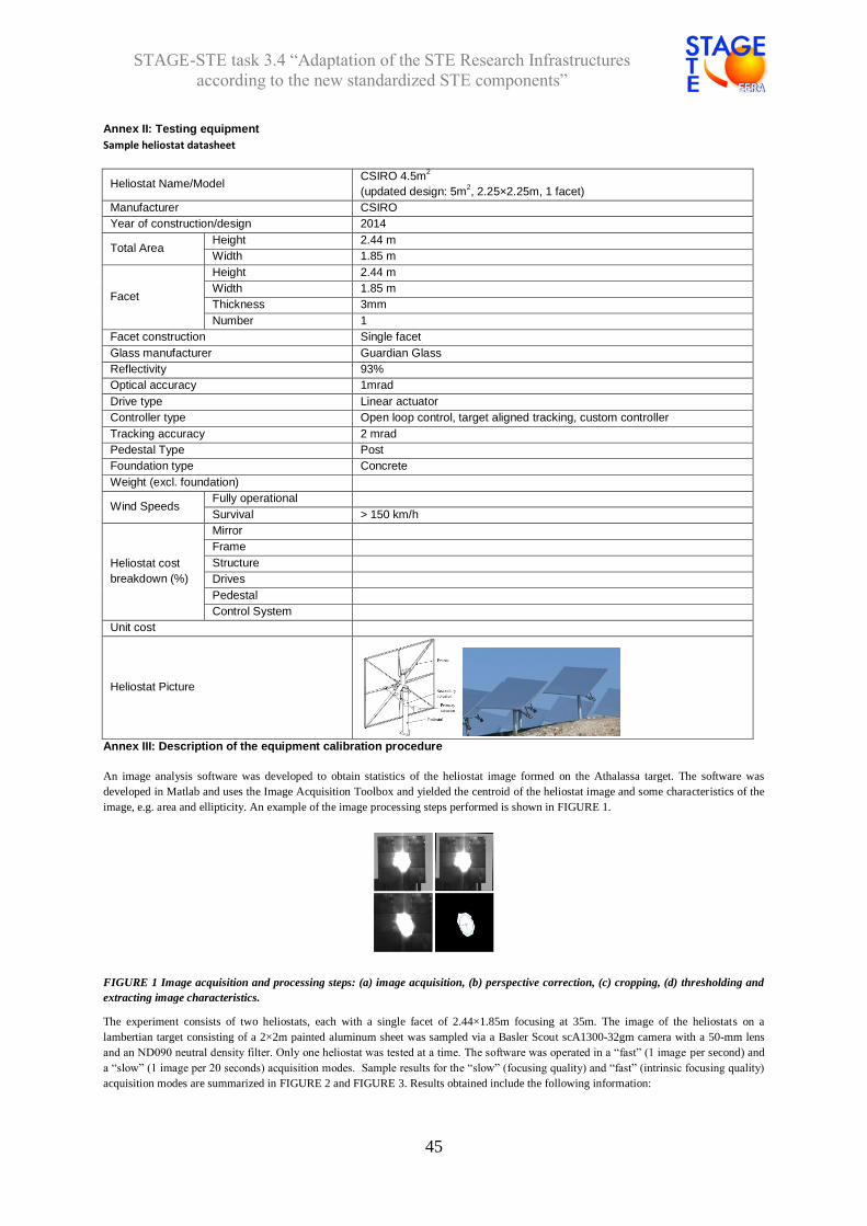
STAGE-STE task 3.4 “Adaptation of the STE Research Infrastructures
according to the new standardized STE components”
45
Annex II: Testing equipment
Sample heliostat datasheet
Heliostat Name/Model CSIRO 4.5m
2
(updated design: 5m2, 2.25×2.25m, 1 facet)
Manufacturer CSIRO
Year of construction/design 2014
Total Area Height 2.44 m
Width 1.85 m
Facet
Height 2.44 m
Width 1.85 m
Thickness 3mm
Number 1
Facet construction Single facet
Glass manufacturer Guardian Glass
Reflectivity 93%
Optical accuracy 1mrad
Drive type Linear actuator
Controller type Open loop control, target aligned tracking, custom controller
Tracking accuracy 2 mrad
Pedestal Type Post
Foundation type Concrete
Weight (excl. foundation)
Wind Speeds Fully operational
Survival > 150 km/h
Heliostat cost
breakdown (%)
Mirror
Frame
Structure
Drives
Pedestal
Control System
Unit cost
Heliostat Picture
Annex III: Description of the equipment calibration procedure
An image analysis software was developed to obtain statistics of the heliostat image formed on the Athalassa target. The software was
developed in Matlab and uses the Image Acquisition Toolbox and yielded the centroid of the heliostat image and some characteristics of the
image, e.g. area and ellipticity. An example of the image processing steps performed is shown in FIGURE 1.
FIGURE 1 Image acquisition and processing steps: (a) image acquisition, (b) perspective correction, (c) cropping, (d) thresholding and
extracting image characteristics.
The experiment consists of two heliostats, each with a single facet of 2.44×1.85m focusing at 35m. The image of the heliostats on a
lambertian target consisting of a 2×2m painted aluminum sheet was sampled via a Basler Scout scA1300-32gm camera with a 50-mm lens
and an ND090 neutral density filter. Only one heliostat was tested at a time. The software was operated in a “fast” (1 image per second) and
a “slow” (1 image per 20 seconds) acquisition modes. Sample results for the “slow” (focusing quality) and “fast” (intrinsic focusing quality)
acquisition modes are summarized in FIGURE 2 and FIGURE 3. Results obtained include the following information:

STAGE-STE task 3.4 “Adaptation of the STE Research Infrastructures
according to the new standardized STE components”
46
The x- and y-axis image centroid locations as a function of time, presented as distance from the target (origin set at target edge,
target is 2x2 m, so an {x,y} coordinate of {1,1} represents target center), and distance from target center normalized by slant
range to yield an angle.
The centroid data is also plotted as a scatter plot of distances from origin (plots of δy vs. δx in [m] and [mrad]).
The image area is calculated both through image processing and through fitting an ellipse to the captured image.
The orientation of the ellipse is presented as the angle between the ellipse primary axis and the vertical
FIGURE 2 Sample results for "slow" acquisition mode. Results show distance and angular position of the image centroids in the x-
(panels a & b) and y- (panels c & d) directions, scatter plots of offset in terms of distance and angle (panels e & f) and image area and
ellipticity (panels g & h, respectively).
In FIGURE 2, the quantity of interest is captured in panel f, where the clustering of points may be visually seen to have an extent of ±4 mrad.
Some outliers may be due to clouds during the acquisition period. Larger angular deviations are noted in the y-centroid position (panel d),
due to the spin-elevation tracking mechanism employed by the heliostats. The offset of the aim point with respect to the target center,
visualized by the center of the clustering of points in panel e, indicates a systematic offset in the aiming position of the heliostat, and the
present data may be used to correct the aiming position.
FIGURE 3 Sample results for "fast" acquisition mode. Results show distance and angular position of the image
centroids in the x- (panels a & b) and y- (panels c & d) directions, scatter plots of offset in terms of distance and angle
(panels e & f) and image area and ellipticity (panels g & h, respectively).
In FIGURE 3, the daily evolution of the measured quantities is presented. The rapid departure of the x-centroid from the
mean position around 16:00 is due to the partial shading of the heliostat by a nearby structure before sunset. Further, “noise”
appearing after 13:00 is due to small clouds present in the sky during the data acquisition period. Similar conclusions as in
the “slow” acquisition case are drawn regarding the overall tracking accuracy.

STAGE-STE task 3.4 “Adaptation of the STE Research Infrastructures
according to the new standardized STE components”
47
Solar thermal collectors
1 - CIEMAT/PSA - ISO9806
Description of Testing Protocols & Protocol requirements
1. Testing firming information (name of laboratory, responsible person/company);
2. Sampling equipment, if any (equipment used to prepare samples and get them ready for testing);
3. Testing procedure;
4. Testing equipment;
5. Description of the equipment calibration procedure/protocol (if any);
1 –Parabolic Trough Test Loop, Loreto Valenzuela/CIEMAT
2 - Cleaning system (vehicle equipped with water cleaning devices) for cleaning mirrors of the parabolic troughs before any test.
Devices and Services portable specular reflectometer is used to measure the cleanliness factor of mirrors
3–Optical and thermal testing of large-size parabolic troughs under real operating conditions. Methodologies followed are the
steady-state energy balance method developed by CIEMAT-PSA and the quasi-dynamic testing procedure of
ISO9806:2017.
4-This large test facility is implemented in a 420mx180m plot of the PSA and it is composed of two fields:
- the North field is designed to install with a E-W orientation complete parabolic trough collectors with a maximun unit length of 180 m. Up to four complete collectors can be installed in parallel.
- the South field is designed to install complete loops of PTC (i.e., several collectors connected in series, with a maximum length of 640 m and oriented North-South. Up to four complete loops can be installed in parallel.
Each field is provided with a complete oil circuit installed in a 160mx40m plot between the two fields, and both circuits
share: an oil expansion tank with a capacity of 25 m3, a gas-fired oil heater with a thermal power of 250 kW, a
meteorological station equipped with solar radiation ambient temperature and wind sensors, and the data acquisition
system (DAS). Additionally to these common elements, the oil circuit associated to the North and South fields are
composed of:
North field: one oil pump (75 m3/h) provided with speed control, one oil cooler refrigerated by air (2 MWt) able to cold the
oil tdown to 70ºC when the ambient air temperature is 40ºC, oil piping connecting the circuit to the common elements (i.e.,
expansion tank and oil heater).
South field: one oil pump (150 m3/h) provided with speed control, one oil cooler refrigerated by air (2 MWt), oil piping
connecting the circuit to the common elements (i.e., expansion tank and oil heater).
Each oil circuit is also provided with an oil draining tank big enough to receive all the oil existing in the circuit, a complete
instrumentation to monitor, oil mass flow, pressure and temperature, as well as control valves to regulate to oil flow to
desired values according to the tests.
5 –PT100 sensors and the pyrheliometer are calibrated once per year
National/international Standards applied. If no standard for these tests is still available, please state it here
ISO9806:2017 Solar energy. Solar thermal collectors. Test method.
IEC/TC 117 – 62862-3-2 Part 3-2 – General requirements and test methods for parabolic-trough collector. Standard under preparation.
Other laboratories where these or similar tests could be done?
HTF Test Loop. Installation also located at PSA.
Round robin test on going or done in the past?.(If Yes, please specify the year and name of the laboratories or facilities
involved)

STAGE-STE task 3.4 “Adaptation of the STE Research Infrastructures
according to the new standardized STE components”
48
2 - CIEMAT/PSA ISO9806
Description of Testing Protocols & Protocol requirements
1. Testing firming information (name of laboratory, responsible person/company);
2. Sampling equipment, if any (equipment used to prepare samples and get them ready for testing);
3. Testing procedure;
4. Testing equipment;
5. Description of the equipment calibration procedure/protocol (if any);
1 –Rotary test bench for parabolic trough collectors (KONTAS),Loreto Valenzuela/CIEMAT
2 - Cleaning system for cleaning mirrors of the parabolic-trough module before any test.Devices and Services portable specular reflectometer is used to measure the cleanliness factor of mirrors. 3 -Optical and thermal testing under real operating conditions of new designs of parabolic-trough collectors and linear Fresnel collectors.
4-The test bench allows the qualification of parabolic trough collector components and complete modules of a length of up to 20 m. It enables for a tracking at any desired angle of incidence of the solar radiation. The test bench rests on rails directly mounted on top of the foundation. The collector itself is mounted on a steel platform with six steel wheels. The rotation of the steel platform on the rails around the central bearing is performed by motors driving four of these wheels. The thermal oil used in this facility (Syltherm 800®) has a maximum working temperature of 400°C and a freezing point of -40°C. The facility’s oil circuit, which has a maximum working pressure of 18 bar, is made up of the following elements:
• Delivering pump able to provide 22m3/h against 3.5 bar • Cooling system with a power of 100 kW@10°C and using R 134 as refrigerant. • 2 x 27-kW electric oil heaters.
The test bench is equipped with instrumentation to measure the thermal oil mass flow using the Coriolis measuring principle avoiding uncertainties of the density. Sensors for measurement of inlet and outlet temperatures are highly precise and may be calibrated on site. The heating and cooling unit dissipates the energy the hot HTF collected on the way through the collector module and ensures a constant HTF temperature (±1K) at the inlet of the collector.
5 –Temperature sensors and pyheliometer are calibrated once per year.
National/international Standardsapplied. If no standard for these tests is still available, please state it here
ISO9806:2017 Solar energy. Solar thermal collectors. Test method.
Other laboratories where these or similar tests could be done?
NREL
Round robin test on going or done in the past?.(If Yes, please specify the year and name of the laboratories or facilities involved)
None

STAGE-STE task 3.4 “Adaptation of the STE Research Infrastructures
according to the new standardized STE components”
49
3- CNRS
Description of Testing Protocols &Protocol requirements
1. Testing firming information (name of laboratory, responsible person/company);
2. Sampling equipment, if any (equipment used to prepare samples and get them ready for testing);
3. Testing procedure;
4. Testing equipment;
5. Description of the equipment calibration procedure/protocol (if any);
1 – CNRS-PROMES, Nicolas Boullet
2 – N/A
3 – Depending on the request
4 – Parabolic trough components: solar receivers, mirrors
5 - Depending on the request
National/international Standards applied. If no standard for these tests is still available, please state it here
No standards available (work in progress)
Other laboratories where these or similar tests could be done?
Yes: CIEMAT and DLR at PSA, other…
Round robin test on going or done in the past ?. (If Yes, please specify the year and name of the laboratories or facilities
involved)
No.

STAGE-STE task 3.4 “Adaptation of the STE Research Infrastructures
according to the new standardized STE components”
50
4- LNEG ISO 9806
Description of Testing Protocols &Protocol requirements
1. Testing firming information (name of laboratory, responsible person/company);
2. Sampling equipment, if any (equipment used to prepare samples and get them ready for testing);
3. Testing procedure;
4. Testing equipment;
5. Description of the equipment calibration procedure/protocol (if any);
1 - Testing firming information
LNEG - Laboratório de Energia Solar (LES)
Maria João Carvalho (e-mail:[email protected]) / Jorge Facão (e-mail: [email protected])
2 - Sampling equipment, if any
Not applicable
3 - Testing procedure
Testing of Solar Thermal Collectors (Liquid heating) according to ISO 9806. Quasi-dynamic test method and Steady State
method. Applicable to flat plate collectors and small concentrating collectors. Thermal performance test up to 100ºC.
4 - Testing equipment
Hydraulic circuit with pressurized water. Data acquisition system (Multimeter Keithley 2700) controlled by in house
software. Pirheliometer CH1 installed in a Solys 2 traker (Kipp&Zonen); Pyrometer (Kipp&Zonen), Electromagnetic flow
meters from ABB, Temperature probes (Platinium Resistence - 100).
5 - Description of the equipment calibration procedure/protocol (if any)
Multimeter Keithley 2700 - annual calibration in the primary laboratory in Portugal – IPQ/LCM
Pirheliometer CH1 – biennial calibration at an accredited calibration laboratory (CENER, Spain)
Pyrometer (Kipp&Zonen) - calibrated internally using the comparison method according to ISO 9847; the reference
pyranometer has biennial calibration at an accredited calibration laboratory (CENER, SPAIN)
Electromagnetic flow meters from ABB - calibrated internally using the comparison method; The reference flowmeter is
calibrated annually in an accredited calibration laboratory (EPAL, Portugal)
Temperature probes (Platinium Resistence - 100) - calibrated internally using the comparison method; The reference
temperature probe has a biennial calibration in an accredited calibration laboratory (IPQ/LCM, Portugal)
National/international Standards applied. If no standard for these tests is still available, please state it here
Thermal performance testing according to ISO 9806
Other laboratories where these or similar tests could be done?
See list of laboratories in http://www.estif.org/solarkeymarknew/contacts/recognised-test-labs
Round robin test on going or done in the past ?. (If Yes, please specify the year and name of the laboratories or facilities
involved)
Participated in Round Robin test in 2010-2011 in the frame of QAiST project.
http://www.estif.org/fileadmin/estif/content/projects/QAiST/QAiST_results/IFEP_CWeissmueller_Proficiency%20test_Final%20report_05Jun12.pdf

STAGE-STE task 3.4 “Adaptation of the STE Research Infrastructures
according to the new standardized STE components”
51
5 – ENEA EN 12975-2 and ISO 9806 accredited laboratory
Description of Testing Protocols &Protocol requirements
1. Testing firming information (name of laboratory, responsible person/company);
2. Sampling equipment, if any (equipment used to prepare samples and get them ready for testing);
3. Testing procedure;
4. Testing equipment;
5. Description of the equipment calibration procedure/protocol (if any);
1 - Testing firming information
Laboratorio qualificazione componenti solari (LQCS) CR ENEA Trisaia – referents Ing. Domenico Marano - e-mail:
[email protected]/ Dott. Vincenzo Sabatelli - e-mail: [email protected]
2 - Sampling equipment, if any
Not applicable
3 - Testing procedure
all the tests required by the legislation tests on solar collectors (EN 12975-2 and ISO 9806) . the laboratory is accredited to test solar collectors up 300°C
4 - Testing equipment
the energetic characterization of concentrating collectors for medium temperature applications through the use of
experimental facilities able to analyze from a thermal point of view these components with working temperature up to 300 °
C.
5 - Description of the equipment calibration procedure/protocol (if any)
all protocol scheduled by standards EN 12975-2
National/international Standards applied. If no standard for these tests is still available, please state it here
Thermal performance testing according to ISO 9806 - EN 12975-2
Other laboratories where these or similar tests could be done?
Italian referent for the European networking solar Key mark
Round robin test on going or done in the past ?. (If Yes, please specify the year and name of the laboratories or facilities
involved)
none
STAGE-STE task 3.4 “Adaptation of the STE Research Infrastructures
according to the new standardized STE components”
52
6 – DLR Tests according to standard ISO 9806
Description of Testing Protocols &Protocol requirements
1. Testing firming information (name of laboratory, responsible person/company);
2. Sampling equipment, if any (equipment used to prepare samples and get them ready for testing);
3. Testing procedure;
4. Testing equipment;
5. Description of the equipment calibration procedure/protocol (if any);
1 - Sopran, Dirk Krüger, DLR, Cologne, Germany
2 - …………………………………
3 - Outdoor thermal testing of small scale and power plant size parabolic trough and fresnel collectors according to standard
ISO 9806, but extended to 200°C. Medium: Water
Other tests to evaluate collectors as e.g. tracking precision, tracking algorithms and torsion
4 – Balance of plant up to 200°C, phyreliometer with temperature compensation, pyranometers, flow meters, temperature
sensors
5 – Phyreliometer and pyranometers: Internal calibration with absolute cavity radiometer. Flow meters with converters: External
calibration. Temperature sensors calibration according to DKD-R 5-1 with temperature sensor calibrator plus relative calibration
including measurement chain. AD converters via voltage transducer. Ambient temperature and wind sensors: External
calibration.
All based on traceable calibrations.
National/international Standards applied. If no standard for these tests is still available, please state it here
Tests according to standard ISO 9806
Other laboratories where these or similar tests could be done?
Round robin test on going or done in the past ?. (If Yes, please specify the year and name of the laboratories or facilities
involved)

STAGE-STE task 3.4 “Adaptation of the STE Research Infrastructures
according to the new standardized STE components”
53
Mirrors
1 - CENER – shape quality
Description of Testing Protocols & Protocol requirements
1. Testing firming information (name of laboratory, responsible person/company); 2. Sampling equipment, if any (equipment used to prepare samples and get them ready for testing); 3. Testing procedure; 4. Testing equipment;
Description of the equipment calibration procedure/protocol (if any)
Description of Testing Protocols &Protocol requirements
Test objective (parameter to be evaluated/analysed):
Geometric characterization of mirror segments and complete concentrators by photogrametry an deflectometry
Testing firming information (name of laboratory, responsible person/company);
CENER, Alberto García de Jalón, Head of Measurement & Characterization unit
Sampling equipment, if any (equipment used to prepare samples and get them ready for testing): N/A
Testing procedure:
Photogrametry:
Geometric characterization determines how much energy will reach the solar receiver tube as a function of the
reconstructed shape of the collector surfaces (considering mirror quality) and comparing it to the amount of energy
that would arrive at an ideal solar receiver tube under similar circumstances.
In heliostats, geometric characterization can be done taking different heliostat positions and wind conditions into
account to analyze the errors caused by gravity and wind loads.
PTC modules and heliostats are characterized to accurately determine the real geometry of the mirror shape. The
infrastructure available can easily be moved to the desired location, making it highly flexible. The technique uses a
high-resolution camera, coded targets and a specific software for post-processing specialized in analyzing the data
acquired.
Deflectometry:
The tool FOCUS used in CENER is based on the fringe reflection theory. In this technique sinusoidal fringe patterns
are projected on a screen and their reflection over a mirror surface is recorded by a camera. The observed distortions
in the image are related directly to surface deviations from ideal geometry. A mathematical model in the software
requires physical input of the geometry of the arrangement in order to convert the reflected fringe patterns into a slope
deviation (SD) from the ideal facet design. Sensitivity values were calculated for every output variable, varying the
input parameters in 37 equally spaced increments across the uncertainty measurements of every measuring device.
The software was executed on an operation cycle fixing the parameters and varying the analyzed. The slope output
were calculated with respect to the variation in the input parameter.
Testing equipment:
- For photogrammetry: Camera, vinyls and software. - For deflectometry: Camera, proyector, screen and software. Description of the equipment calibration procedure/protocol (if any): N/A
National/international Standards applied for this Test. If no standard for these tests is still available, please state it here
There is not standard in force for this test. We use an internal method.
Other laboratories where these or similar tests could be done?
- CSP Services - PSA - ISE - ENEA
Round robin test on going or done in the past ? (If Yes, please specify the year and name of the laboratories or facilities involved)
2015: Round Robin Test within StaMeP / SolarPACES Task III

STAGE-STE task 3.4 “Adaptation of the STE Research Infrastructures
according to the new standardized STE components”
54
2 - CENER – Mirrors durability (tests according to the ISO 9227, ISO
6270-2,ISO11507)
Description of Testing Protocols & Protocol requirements
1. Testing firming information (name of laboratory, responsible person/company); 2. Sampling equipment, if any (equipment used to prepare samples and get them ready for testing); 3. Testing procedure; 4. Testing equipment; 5. Description of the equipment calibration procedure/protocol (if any)
Description of Testing Protocols &Protocol requirements
Test objective (parameter to be evaluated/analysed): Temperature and humidity cycling test: The purpose is to determine the capacity of a solar component sample to resist
sudden changes in temperature and humidity.
Salt spray test: “Corrosion tests in artificial atmospheres. Salt spray tests.” The purpose is to determine resistance to
corrosion of a solar component sample exposed to constant neutral salt spray simulating an extreme saline atmosphere.
Condensation test: The purpose is to determine the resistance to corrosion of a solar component sample under exposure to
constant condensation-water atmospheres.
UV radiation exposure test: The purpose is to determine the ability of a solar component sample to resist UV radiation.
Testing firming information (name of laboratory, responsible person/company);
CENER, Alberto García de Jalón, Head of Measurement & Characterization unit
Sampling equipment, if any (equipment used to prepare samples and get them ready for testing): N/A
Testing procedure:
These kind of tests are focused on analysis of the degradation of the components against different ambient agents. These
tests consist in introducing several samples in climatic chambers during a large period. The aim of the test is evaluating the
degradation of the components along the time. It is useful to measure at the beginning and at the end the optical properties
of the component in order to see the difference before and after testing.
Testing equipment:
- Climate cycles chamber - Wet heat test chamber - Saline fog test chamber - Ultraviolet degradation test chamber
Description of the equipment calibration procedure/protocol (if any):
Durability tests: Calibration of all reference sensors for temperature and humidity measurements.
National/international Standards applied for this Test. If no standard for these tests is still available, please state it here
- Temperature and humidity cycling test - Salt spray test according to the ISO 9227 standard - Condensation test according to the ISO 6270-2 standard - UV radiation exposure test according to the ISO 11507 standard
Other laboratories where these or similar tests could be done?
- ISE - DLR - PSA - ENEA
Round robin test on going or done in the past ? (If Yes, please specify the year and name of the laboratories or facilities involved) N/A
STAGE-STE task 3.4 “Adaptation of the STE Research Infrastructures
according to the new standardized STE components”
55
3 - CENER – Mirrors reflectivity
Description of Testing Protocols & Protocol requirements
1. Testing firming information (name of laboratory, responsible person/company); 2. Sampling equipment, if any (equipment used to prepare samples and get them ready for testing); 3. Testing procedure; 4. Testing equipment; 5. Description of the equipment calibration procedure/protocol (if any)
Description of Testing Protocols &Protocol requirements
Test objective (parameter to be evaluated/analysed):
Solar reflectance measurements
Testing firming information (name of laboratory, responsible person/company);
CENER, Alberto García de Jalón, Head of Measurement & Characterization unit
Sampling equipment, if any (equipment used to prepare samples and get them ready for testing): N/A
Testing procedure:
Spectrophotometer equipment is used to measure the hemispherical spectral reflectance curve between 300
nm and 2500 nm using an integrating sphere.
Testing equipment:
- Spectrophotometer OL-750 for small samples
Description of the equipment calibration procedure/protocol (if any):
A calibrated reference is used for reflectance measurements.
National/international Standards applied for this Test. If no standard for these tests is still available, please state it here
There are not standards in force. Spectral distribution at air mass AM1.5 based on the solar spectrum of the Standard ASTM
G173 or ISO 9845-1.
Other laboratories where these or similar tests could be done?
- ISE - DLR - PSA - ENEA - CEA
Round robin test on going or done in the past ?. (If Yes, please specify the year and name of the laboratories or facilities involved)
2013: SolarPACES Task III Reflectance Round Robin (SRRR)
STAGE-STE task 3.4 “Adaptation of the STE Research Infrastructures
according to the new standardized STE components”
56
4 - CENER – Mirrors resistance to impacts (ISO 9806)
Description of Testing Protocols & Protocol requirements
1. Testing firming information (name of laboratory, responsible person/company); 2. Sampling equipment, if any (equipment used to prepare samples and get them ready for testing); 3. Testing procedure; 4. Testing equipment; 5. Description of the equipment calibration procedure/protocol (if any)
Description of Testing Protocols &Protocol requirements
Test objective (parameter to be evaluated/analysed):
Mechanical resistance to impacts
Testing firming information (name of laboratory, responsible person/company);
CENER, Alberto García de Jalón, Head of Measurement & Characterization unit
Sampling equipment, if any (equipment used to prepare samples and get them ready for testing):
Testing procedure:
Resistance to impact
The main purpose of this infrastructure is to test the impact on mirror facets used in solar thermal power plants to
determine their resistance to hail storms.
This testbed is comprised of a compressor which can propel ice balls at a speed of 23 m/s simulating impacts in a
hail storm.
Testing equipment:
- Testbed for ice ball impact resistance.
Description of the equipment calibration procedure/protocol (if any):
Calibration of the most important sensors:
- Laser-speed meter
- Weight scale
National/international Standards applied for this Test. If no standard for these tests is still available, please state it here
- ISO 9806
Other laboratories where these or similar tests could be done?
- ISE - DLR - PSA - ENEA
Round robin test on going or done in the past ?. (If Yes, please specify the year and name of the laboratories or facilities involved)
N/A
STAGE-STE task 3.4 “Adaptation of the STE Research Infrastructures
according to the new standardized STE components”
57
5 - CIEMAT - shape quality for linear PTC, dish , Fresnel
Description of Testing Protocols & Protocol requirements
1. Testing firming information (name of laboratory, responsible person/company); 2. Sampling equipment, if any (equipment used to prepare samples and get them ready for testing); 3. Testing procedure; 4. Testing equipment; 5. Description of the equipment calibration procedure/protocol (if any)
Description of Testing Protocols & Protocol requirements
Test objective (parameter to be evaluated/analysed):
geometrical assessment of facets and concentrators for solar concentrating technology
Testing firming information (name of laboratory, responsible person/company);
Concentrating solar systems laboratory, Jesús Fernández-Reche, CIEMAT-PSA.
Sampling equipment, if any (equipment used to prepare samples and get them ready for testing): NA
Testing procedure:
The concentrators used in solar thermal systems (heliostats, parabolic-trough collectors, parabolic dishes, Fresnel lenses, etc.) require
high precision concentration of the solar radiation for it to be suitable and most of it incident on the receiver component (receiver tubes
in parabolic-trough collectors, receivers in tower systems, parabolic dishes, Fresnel lenses, etc.). The laboratory of the Concentrating
Solar Systems Unit has a specific activity line for the geometric characterization of these concentrators. Photogrammetry is used to
quantify the optical quality of:
Parabolic-trough collector facets
Parabolic-trough collector modules
Heliostat facets
Heliostats
Fresnel lenses and reflectors
Parabolic dishes
Structural frames
Etc.
Photogrammetry consists of three-dimensional modelling of any object from photographs that capture it from different angles. Based on
these photographs, the three-dimensional coordinates (x, y, z) can be calculated for the points of interest on the object being modelled.
Photogrammetry modelling is precise up to 1:50000 (precisions on the order of 0.1 mm for parabolic-trough collector facets and 0.6-0.7
mm for 12-m-long parabolic-trough modules).
Additionally, a ray-tracing software package for model analysis and calculation of relevant parameters for 2D and 3D geometries in the
MatLab environment has been developed in house.
Among the parameters that can be calculated from the model built by photogrammetry are:
Deviations of real from theoretical surface on coordinates x, y, z.
Gravity deformation between different concentrator orientations.
Angular deviation from the normal vector to the surface compared to the theoretical normal vector.
Deviation of reflected rays on the reflective surface of the module compared to the theoretical concentrator focus.
Intercept factor.
Testing equipment;:
Photographic Camera, laser-scanner, vinyls and software
Description of the equipment calibration procedure/protocol (if any): NA
National/international Standards applied for this Test. If no standard for these tests is still available, please state it here
Spanish standard under development. Current procedure meets this unpublished standards.
Other laboratories where these or similar tests could be done?
CENER
CSP Services ISE ENEA
A) Round robin test on going or done in the past ?. (If Yes, please specify the year and name of the laboratories or facilities involved)
- 2015: Round Robin Test within StaMeP / SolarPACES Task III - 2017: Round robin test in the frame of SFERA-II project (WP14)

STAGE-STE task 3.4 “Adaptation of the STE Research Infrastructures
according to the new standardized STE components”
58
6 - CIEMAT - Mirrors durability outdoor aging (test according to ISO 9223 and ISO 9226)
Description of Testing Protocols & Protocol requirements
1-Testing firming information (name of laboratory, responsible person/company); 2-Sampling equipment, if any (equipment used to prepare samples and get them ready for testing); 3-Testing procedure; 4-Testing equipment; 5-Description of the equipment calibration procedure/protocol (if any)
Description of Testing Protocols &Protocol requirements
Test objective (parameter to be evaluated/analysed):
Evaluation of durability of reflector degradation mechanisms under natural aging (atmospheres with different corrosivities).
Testing firming information (name of laboratory, responsible person/company);
OPAC laboratory, joint research laboratory at the PSA between CIEMAT and DLR.
CIEMAT responsible: Aránzazu Fernández-García
DLR responsible: Florian Sutter
Sampling equipment, if any (equipment used to prepare samples and get them ready for testing):
Not applicable
Testing procedure:
Evaluation of durability of materials by exposure in Outdoor Exposure Testing (OET). The samples were installed at the
sites on specifically designed exposure racks. They consist of frames made out of standard aluminum profiles. The inert
plastic and ceramic support elements prevent contact to the aluminum structure and possible electrochemical interactions
between the sample and the rack. The structures are oriented facing south (north on the southern hemisphere) to
maximize the irradiation reaching the sample surfaces. The only exception is the site of Almería. Here the rack is installed
on an inner city roof top and the reflection of the mirror samples would be disturbing neighbouring buildings. This is why
this rack faces in south-east direction. Sites description:
Location Lat. Long. Mean
T. [ºC]
Sum GHI
[kWh/m2/a]
Sum DNI
[kWh/m2/a]
Mean wind
speed
[m/s]
Mean
r.h. [%]
TOW
(%)
Almeria 36.84°N 2.46°W 19.1 1938 - 3.8 65 -
Tabernas 37.1°N 2.35°W 18.3 1828 2133 3.2 59.5 16.1
Missour 32.86°N 4.11°W 18 2023 2156 3.6 48.1 10.6
Erfoud 31.49°N 4.22°W 22.2 2044 2133 3.1 30.1 1.7
Zagora 30.27°N 5.85°W 23.9 2174 2341 3.8 23.4 0.9
Israel 31.02°N 35.09°E 19 1980 2200 2.5 56 -
Antofagasta 24.09°S 69.92°W Tbd Tbd Tbd Tbd Tbd Tbd
Chajnantor 22.96°S 67.79°W Tbd Tbd Tbd Tbd Tbd Tbd
Odeillo 42.49°N 2.03°E Tbd Tbd Tbd Tbd Tbd Tbd
Testing equipment:
Some of the sites are equipped with meteo data stations.
Description of the equipment calibration procedure/protocol (if any):
Annual maintenance plan.
National/international Standards applied for this Test. If no standard for these tests is still available, please state it here
The determination of corrosivity is performed according to ISO 9223 and ISO 9226.
Other laboratories where these or similar tests could be done?
LNEG – Portugal, Q-Labs
Round robin test on going or done in the past ?. (If Yes, please specify the year and name of the laboratories or facilities involved)
No

STAGE-STE task 3.4 “Adaptation of the STE Research Infrastructures
according to the new standardized STE components”
59
7 -CIEMAT - Mirrors durability accelerated ageing (different ISO)
Description of Testing Protocols & Protocol requirements
1-Testing firming information (name of laboratory, responsible person/company); 2-Sampling equipment, if any (equipment used to prepare samples and get them ready for testing); 3-Testing procedure; 4-Testing equipment; 5-Description of the equipment calibration procedure/protocol (if any)
Description of Testing Protocols &Protocol requirements
1. Test objective (parameter to be evaluated/analysed):
Durability of reflectors under accelerated aging tests
2. Testing firming information (name of laboratory, responsible person/company);
OPAC laboratory, joint research laboratory at the PSA between CIEMAT and DLR.
CIEMAT responsible: Aránzazu Fernández-García
DLR responsible: Florian Sutter
3. Sampling equipment, if any (equipment used to prepare samples and get them ready for testing):
Sample size should be 10 x 10cm²
4. Testing procedure:
see section 5.
5. Testing equipment:
Accelerated aging test Testing procedure Testing equipment
THERMAL STABILITY Constant temperature Nabertherm LT 24/12 and LT 40/12 Muffle Furnaces
DAMP HEAT IEC 62108 (section 10.7a and 10.7 b) Memmert HCP108
THERMAL CYCLING IEC 61215 (Section 10.11) or IEC 62108 (Section 10.6)
SC340MH by Vöstch
HUMIDITY CLIMATIC / CONDENSATION
ISO 6270-2CH Ineltec CKEST 300
HUMIDITY FREEZE IEC 62108 (test 10.8) SC340MH by Vöstch
ACID RAIN (KESTERNICH TEST) DIN 50018/ ISO 3231/ISO 6988 HK300M by Köhler
LOW CONCENTRATIONS OF POLLUTING GAS(ES) TEST
ISO 21207 ISO 10062 ISO 6988
Vöstch VCC3 0034
SALT SPRAY (NEUTRAL SALT SPRAY, NSS, AND COPPER-ACCELERATED ACETIC ACID SALT SPRAY, CASS)
ISO 9227 Vötsch VSC450 and Erichsen 608/1000L
UV RADIATION EXPOSURE ISO 16474-3 ATLAS UV-Test
UV RADIATION EXPOSURE Constant UV Hönle UVA Cube
MACHU TEST Quality test guideline SC100 heatable water bath
EROSION DUE TO SAND STORM MIL-STD-810G, ISO 12103-1 Control Técnica/ITS GmbH
(Close loop)
EROSION RESISTANCE DIN 52348 In-house sand trickling
CLEANING ABRASION TEST ISO 1998 Erichsen 494
ABRASION RESISTANCE ISO 9211-4 Taber 5750 linear abraser
CROSS CUT TEST ISO 2409 Lumakin A-29
ADHESION TEST ASTM D 4541, ASTM D 7234 and ISO 4624
Automatic Adhesion Tester PosiTest AT-A
Description of the equipment calibration procedure/protocol (if any):
Annual calibration by the technicians
National/international Standards applied for this Test. If no standard for these tests is still available, please state it here
see section 5.
Other laboratories where these or similar tests could be done?
LNEG, CEA, Tecnalia, CENER, NREL, Q-labs
Round robin test on going or done in the past ?. (If Yes, please specify the year and name of the laboratories or facilities involved)
A round Robin for Durability Tests was performed in 2016 in the frame of WP8 of STAGE-STE project. The participating Laboratories were: CEA (France), DLR/CIEMAT (Spain), LNEG (Portugal), CENER (Spain), and TECNALIA (Spain)

STAGE-STE task 3.4 “Adaptation of the STE Research Infrastructures
according to the new standardized STE components”
60
8 -CIEMAT/DLR - Reflectance evaluation
Description of Testing Protocols & Protocol requirements
1-Testing firming information (name of laboratory, responsible person/company); 2-Sampling equipment, if any (equipment used to prepare samples and get them ready for testing); 3-Testing procedure; 4-Testing equipment; 5-Description of the equipment calibration procedure/protocol (if any)
Description of Testing Protocols &Protocol requirements Test objective (parameter to be evaluated/analysed):
Reflectance of solar reflectors
Testing firming information (name of laboratory, responsible person/company);
OPAC laboratory, joint research laboratory at the PSA between CIEMAT and DLR.
CIEMAT responsible: Aránzazu Fernández-García
DLR responsible: Florian Sutter
Sampling equipment, if any (equipment used to prepare samples and get them ready for testing):
Samples must be received in 10 x 10 cm2 size. The sample should be cleaned carefully with demineralized water and a
soft cloth before the optical measurement. Once the sample is dry, filtered pressurized air may be used to remove any
remaining dust particles on the reflector surface. The reflector surface may only be touched with gloves.
Testing procedure:
Optical reflectance analysis is performed according to the actual SolarPACES reflectance measurement guideline. The
measurement process consists on measuring the spectral hemispherical and the monochromatic specular reflectance.
The spectral hemispherical reflectance is measured in the wavelength range of λ = [280,2500] nm, using 5 nm intervals at
an incidence angle of θ = 8°. Three measurements are taken on each sample, rotating the sample by 90º each time.
Following ASTM Standard E903-82 (92) and using the ASTM G173-03 solar spectrum, the solar-weigthed hemispherical
reflectance is calculated.
The monochromatic specular reflectance within a defined acceptance half-angle of φ = 12.5 mrad is measured with a
portable specular reflectometer. This instrument uses a parallel beam with an incidence angle of θi = 15° and a wavelength
range between 635 and 685 nm, with a peak at 660 nm (λ = 660 nm). Each sample is measured in five different positions.
Testing equipment:
Perkin-Elmer Lambda1050 spectrophotometer with an integrating sphere of 150 mm diameter and Devices & Services 15R-USB portable specular reflectometer.
Description of the equipment calibration procedure/protocol (if any):
Both equipment are calibrated every day with a 2nd
surface reference reflectance standard (calibrated in the range 280-
2500 nm by the dutch company OMT Solutions with traceability to NIST). The spectrophotometer is calibrated every year
by a technician from Perkin Elmer.
National/international Standards applied for this Test. If no standard for these tests is still available, please state it here
SolarPACES Guideline, V3.0
Other laboratories where these or similar tests could be done?
CEA, CENER, Cranfield University, Fraunhofer ISE, LNEG, NREL, Tecnalia, Tekniker
Round robin test on going or done in the past ?. (If Yes, please specify the year and name of the laboratories or facilities involved)
2010: SolarPACES Task III: Round robin test. DLR, CIEMAT, NREL 2013: SolarPACES Task III Reflectance Round Robin test. ENEA, DLR, CIEMAT, ISE, CENER, CEA 2016-2017: STAGE-STE Durability and Reflectance Round Robin test. CIEMAT, DRL, CEA, CENER, Tecnalia, LNEG.

STAGE-STE task 3.4 “Adaptation of the STE Research Infrastructures
according to the new standardized STE components”
61
9 ENEA - shape quality for linear Fresnel concentrators
Description of Testing Protocols & Protocol requirements
1-Testing firming information (name of laboratory, responsible person/company); 2-Sampling equipment, if any (equipment used to prepare samples and get them ready for testing); 3-Testing procedure; 4-Testing equipment; 5-Description of the equipment calibration procedure/protocol (if any)
Description of Testing Protocols &Protocol requirements
Test objective (parameter to be evaluated/analysed): shape quality and main features of panels for linear Fresnel
concentrators
1. Testing firming information (name of laboratory, responsible person/company): Solar Collector Optics Laboratory; Marco
Montecchi ENEA
2. Sampling equipment, if any (equipment used to prepare samples and get them ready for testing):
3. Testing procedure: i) adjustment of the attaching points in nominal position; ii) installation of the specimen to be measured;
iii) in case of different temperature between storehouse and laboratory, wait 6 hours for thermal equilibrium; iv) display a
sequence of strips, horizontal and vertical, on the LCD monitor while the camera synchronously acquire the sequence of
images of the panel surface; v) data processing for evaluating the unit vector normal to the surface and shape computing; vi)
evaluation of the main features for CSP purposes (deviation from nominal values of shape, slope, and focus; intercept factor
within the secondary aperture at standard sun shape versus the longitudinal angle of incidence)
4. Testing equipment: VISproLF
5. Description of the equipment calibration procedure/protocol (if any): position and attitude of the camera used in the
VISproLT are obtained by analysing the image of a special pattern installed in known position. Similarly attitude and position
of the LCD monitor used like light-source is obtained by displaying a regular pattern and observing the image reflected by a
first surface float glass mirror put in the sample position.
National/international Standards applied for this Test. If no standard for these tests is still available, please state it here
I do not know of any standard
Other laboratories where these or similar tests could be done?
VISproLT differs from the others based on deflectometry because the position of the point source imaged in a given point of the mirror surface is totally digital. Actually the instrument is unique. Anyway similar test can be accomplished at DLR, CIEMAT and ISE laboratory.
Round robin test on going or done in the past ?. (If Yes, please specify the year and name of the laboratories or facilities involved)
In SolarPACES Task III a round robin was launched several years ago, but at this time the agreement is not satisfactory.
10 -ENEA - shape quality for linear PTC concentrators
Description of Testing Protocols & Protocol requirements
1-Testing firming information (name of laboratory, responsible person/company); 2-Sampling equipment, if any (equipment used to prepare samples and get them ready for testing); 3-Testing procedure; 4-Testing equipment; 5-Description of the equipment calibration procedure/protocol (if any)
Description of Testing Protocols &Protocol requirements
Test objective (parameter to be evaluated/analysed): shape quality and main features of panels for parabolic trough
concentrator
1. Testing firming information (name of laboratory, responsible person/company): Solar Collector Optics Laboratory; Marco
Montecchi ENEA
2. Sampling equipment, if any (equipment used to prepare samples and get them ready for testing):
3. Testing procedure: i) adjustment of the facet attaching points in nominal position; ii) installation of the specimen to be
measured; iii) in case of different temperature between storehouse and laboratory, wait 6 hours for thermal equilibrium; iv)
scansion of the reflecting surface; v) data processing for evaluating the unit vector normal to the surface and shape
computing; vi) evaluation of the main features for CSP purposes (deviation from nominal values of shape, slope, and focus;
intercept factor at standard sun shape versus the longitudinal angle of incidence)
4. Testing equipment: VISproPT
5. Description of the equipment calibration procedure/protocol (if any): position and attitude of the two cameras of the
VISprofile are obtained by analysing the image of a special pattern installed in known position. The point-source array
alignment is periodically check by a laser optical level; its distance from the reference plane is measured by a meter.

STAGE-STE task 3.4 “Adaptation of the STE Research Infrastructures
according to the new standardized STE components”
62
National/international Standards applied for this Test. If no standard for these tests is still available, please state it here
At this time there is just a very preliminary draft prepared by an expert group in SolarPACES Task III. The result agreement is not good.
Other laboratories where these or similar tests could be done?
VISproPT differs from the others based on deflectometry because the position of the point source imaged in a given point of the mirror surface is totally digital. Actually the instrument is unique. Anyway similar test can be accomplished at DLR, CIEMAT and ISE laboratory.
Round robin test on going or done in the past ?. (If Yes, please specify the year and name of the laboratories or facilities involved)
In SolarPACES Task III a round robin was launched several years ago, but at this time the agreement is not satisfactory.
11 -ENEA - - shape quality for dish reflectors
Description of Testing Protocols & Protocol requirements
1-Testing firming information (name of laboratory, responsible person/company); 2-Sampling equipment, if any (equipment used to prepare samples and get them ready for testing); 3-Testing procedure; 4-Testing equipment; 5-Description of the equipment calibration procedure/protocol (if any)
Description of Testing Protocols &Protocol requirements
Test objective (parameter to be evaluated/analysed): canting guidance, shape measurement and performance prediction
(intercept factor, solar yield, flux profile, ..) of dish reflectors
1. Testing firming information (name of laboratory, responsible person/company): Solar Collector Optics Laboratory; Marco
Montecchi ENEA
2. Sampling equipment, if any (equipment used to prepare samples and get them ready for testing): a total station Leica
TDA5005 is used to centre the LCD monitor respect to the dish optical axis, orthogonal to it, and at controlled distance by the
focus point, as well as to set front and rear sights (aiming system) for aiming the dish towards the observer
3. Testing procedure: i) install the LCD monitor and the aiming system; ii) aim the dish toward the observer (camera); iii)
display a sequence of strips, horizontal and vertical, on the LCD monitor while the camera synchronously acquire the
sequence of images of the dish surface; iv) process the images for evaluating the unit vector normal in correspondence of
each pixel; v) combine slope and conic reflectance (got with the SMQ set up on small flat specimen of the reflective material)
experimental data to predict the main dish features (intercept factor, solar yield, flux profile, ..)
4. Testing equipment: VISdish
5. Description of the equipment calibration procedure/protocol (if any): determination of characteristic matrix and
distortion coefficients of the camera lens according to one of the procedures suggested in photogrammetry
National/international Standards applied for this Test. If no standard for these tests is still available, please state it here
I do not know of any standard
Other laboratories where these or similar tests could be done?
AIMFAST by NREL, Color-Coded Targets by DLR and photogrammetry by CIEMAT-PSA
Round robin test on going or done in the past ?. (If Yes, please specify the year and name of the laboratories or facilities involved)

STAGE-STE task 3.4 “Adaptation of the STE Research Infrastructures
according to the new standardized STE components”
63
12 -ENEA - profile quality
Description of Testing Protocols & Protocol requirements
1-Testing firming information (name of laboratory, responsible person/company); 2-Sampling equipment, if any (equipment used to prepare samples and get them ready for testing); 3-Testing procedure; 4-Testing equipment; 5-Description of the equipment calibration procedure/protocol (if any)
Description of Testing Protocols &Protocol requirements
Test objective (parameter to be evaluated/analysed): flux profile in the plane orthogonal to the paraboloid optical axis and
crossing the focal point of dish reflectors
1. Testing firming information (name of laboratory, responsible person/company): Solar Collector Optics Laboratory; Marco
Montecchi ENEA
2. Sampling equipment, if any (equipment used to prepare samples and get them ready for testing): a total station Leica
TDA5005 is used to centre the diffusive screen to the dish optical axis, orthogonal to it, and crossing the focal point
3. Testing procedure: i) install the diffusive screen, the camera and the flat mirror for the one Sun calibration; ii) in tracking
condition acquire a set of images at increasing exposure times starting from the one just below saturation to a greater value
for which only the peripheral region of the solar spot appears not saturated; iii) aim the dish to send only the reflection of the
flat mirror on the diffusive scree and acquire an image; iv) process the images to compose a 64 bit float image where the
pixel values are normalized to one Sun
4. Testing equipment: FluxMapper
5. Description of the equipment calibration procedure/protocol (if any): determination of characteristic matrix and distortion
coefficients of the camera lens according to one of the procedures suggested in photogrammetry
National/international Standards applied for this Test. If no standard for these tests is still available, please state it here
I do not know of any standard
Other laboratories where these or similar tests could be done?
DLR & CIEMAT at PSA
Round robin test on going or done in the past ?. (If Yes, please specify the year and name of the laboratories or facilities involved)
No at my knowledge
STAGE-STE task 3.4 “Adaptation of the STE Research Infrastructures
according to the new standardized STE components”
64
13 - ENEA - The reflecting surface
Description of Testing Protocols & Protocol requirements
1-Testing firming information (name of laboratory, responsible person/company); 2-Sampling equipment, if any (equipment used to prepare samples and get them ready for testing); 3-Testing procedure; 4-Testing equipment; 5-Description of the equipment calibration procedure/protocol (if any)
Description of Testing Protocols &Protocol requirements
Test objective (parameter to be evaluated/analysed): solar near-specular reflectance and solar conic reflectance versus
incidence and acceptance angles
1. Testing firming information (name of laboratory, responsible person/company): Solar Collector Optics Laboratory; Marco
Montecchi ENEA
2. Sampling equipment, if any (equipment used to prepare samples and get them ready for testing):
3. Testing procedure: i) check of the reflecting surface (cleanness, scratches, ); ii) measure near-normal hemispherical
reflectance in the solar wavelength range (at least for two different orientations with the light-beam kept close to the central
position); iii) measure near-specular reflectance at near-normal, at several acceptance angles in the range of interest
(typically 3-25 mrad) and at three different wavelengths (451.5 532.5 and 661 nm); iv) evaluate the equivalent roughness by
data modelling with the Total Integrated Scattering relationship; v) off-normal reflectance prediction by means of the
Equivalent Model Algorithm; vi) prediction of solar near-specular reflectance and solar conic reflectance versus incidence
and acceptance angles
4. Testing equipment: Perkin Elmer Lambda 950S and Solar Mirror Qualification (SMQ) set-up
5. Description of the equipment calibration procedure/protocol (if any): 1h warming-up before start measurements; the
baseline of the spectrophotometer and the reference signals of the SMQ are accomplished with a first surface aluminium
reference mirror
National/international Standards applied for this Test. If no standard for these tests is still available, please state it here
The SMQ set-up and the procedure itself are among the ones considered by the expert group which is drafting the reflectance guidelines in SolarPACES Task III.
Other laboratories where these or similar tests could be done?
VLABS at Fraunhofer ISE and S2R at CIEMAT-DLR (PSA)
Round robin test on going or done in the past ?. (If Yes, please specify the year and name of the laboratories or facilities involved)
SRRR, SolarPACES Reflectance Round Robin, coordinated by ENEA was launched in September 2012 following a “parallel” approach (similar sample-kits have been distributed among the participants). Actually the active institutions are: CEA, CENER, CIEMAT, CNRS,DLR, ENEA, ISE, UNIZAR
STAGE-STE task 3.4 “Adaptation of the STE Research Infrastructures
according to the new standardized STE components”
65
14 - LNEG reflectance evaluation in the solar spectrum (ASTM E903-12, ASTM G173,
ISO 9845-1)
Description of Testing Protocols & Protocol requirements
1. Testing firming information (name of laboratory, responsible person/company); 2. Sampling equipment, if any (equipment used to prepare samples and get them ready for testing); 3. Testing procedure; 4. Testing equipment; 5. Description of the equipment calibration procedure/protocol (if any)
Description of Testing Protocols &Protocol requirements Test objective (parameter to be evaluated/analysed):
Measurement of solar hemispherical reflectance Testing firming information (name of laboratory, responsible person/company);
LNEG - Laboratório de Energia Solar (LES)
Maria João Carvalho (e-mail:[email protected]) / Maria Teresa Chambino (e-mail: [email protected])
Sampling equipment, if any (equipment used to prepare samples and get them ready for testing):
Not applicable
Testing procedure:
Measurement of hemispherical reflectance for the wavelength range 250-2500nm and calculation of the solar-weighted
reflectance using the standard solar spectrum of ASTM G173 or ISO 9845.
Testing equipment:
Spectrophotometer Perkin Elmer Lambda 950 with and 150 mm diameter InGaAs integrating sphere.
Description of the equipment calibration procedure/protocol (if any):
The Spectrophotometer has a regular internal calibration. The equipment is submitted to annual maintenance inspections
performed by the company representing the manufacturer of the equipment.
National/international Standards applied for this Test. If no standard for these tests is still available, please state it here
The following standards are relevant for this measurement:
ASTM E903-12, Standard method for solar absorptance, reflectance and transmittance of materials using integrating
Spheres
ASTM G173 - 03(2012) - Standard Tables for Reference Solar Spectral Irradiances: Direct Normal and Hemispherical on
37° Tilted Surface
ISO 9845-1:1992 - Solar energy - Reference solar spectral irradiance at the ground at different receiving conditions - Part
1: Direct normal and hemispherical solar irradiance for air mass 1,5
Other laboratories where these or similar tests could be done?
CEA (France), DLR/CIEMAT (Spain), CENER (Spain), and TECNALIA (Spain) among others.
Round robin test on going or done in the past? (If Yes, please specify the year and name of the laboratories or facilities involved)
A round Robin for the measurement of solar hemispherical reflectance was performed in 2016 in the frame of WP8 of STAGE-
STE project. The participating Laboratories were: CEA (France), DLR/CIEMAT (Spain), LNEG (Portugal), CENER (Spain), and
TECNALIA (Spain).
STAGE-STE task 3.4 “Adaptation of the STE Research Infrastructures
according to the new standardized STE components”
66
15 - LNEG - Mirrors durability outdoor aging (according to ISO 9223 and ISO 9226)
Description of Testing Protocols & Protocol requirements
1. Testing firming information (name of laboratory, responsible person/company); 2. Sampling equipment, if any (equipment used to prepare samples and get them ready for testing); 3. Testing procedure; 4. Testing equipment; 5. Description of the equipment calibration procedure/protocol (if any)
Description of Testing Protocols &Protocol requirements Test objective (parameter to be evaluated/analysed):
Evaluation of durability of materials degradation mechanisms under natural aging (atmospheres with different corrosivities)
Testing firming information (name of laboratory, responsible person/company);
LNEG - Laboratório de Materiais e Revestimentos (LMR).
Teresa Cunha Diamantino (e-mail: [email protected])
Sampling equipment, if any (equipment used to prepare samples and get them ready for testing):
Not applicable
Testing procedure:
Evaluation of durability of materials by exposure in two Outdoor Exposure Testing (OET) Sites: LUMIAR/LISBOA-
PORTUGAL with corrosivity C2-C3 (low-medium corrosivity) and SINES-PORTUGAL with corrosivity C5-CX (very high-
extreme corrosivity).
Testing equipment;:
Description of the equipment calibration procedure/protocol (if any):
Annual maintenance plan.
National/international Standards applied for this Test. If no standard for these tests is still available, please state it here
The construction of these two OET sites followed the standards ISO 8565 and ISO 2810 and have sensors for measurement of temperature, humidity and global solar radiation. Determination of chloride deposition rate was performed by the wet candle method and determination of sulfur dioxide deposition rate on lead dioxide sulfation plates according to ISO 9225. The determination of corrosivity is performed according to ISO 9223 and ISO 9226.
Other laboratories where these or similar tests could be done?
CENIM - Spain
Round robin test on going or done in the past ?. (If Yes, please specify the year and name of the laboratories or facilities involved)
No
STAGE-STE task 3.4 “Adaptation of the STE Research Infrastructures
according to the new standardized STE components”
67
16 - LNEG – Mirrors microstructural and surface characterization
Description of Testing Protocols & Protocol requirements
1. Testing firming information (name of laboratory, responsible person/company); 2. Sampling equipment, if any (equipment used to prepare samples and get them ready for testing); 3. Testing procedure; 4. Testing equipment; 5. Description of the equipment calibration procedure/protocol (if any)
Description of Testing Protocols &Protocol requirements Test objective (parameter to be evaluated/analysed):
Morphological and Chemical Characterization of Materials
Testing firming information (name of laboratory, responsible person/company);
LNEG - Laboratório de Materiais e Revestimentos (LMR).
Teresa Cunha Diamantino (e-mail: [email protected])
Sampling equipment, if any (equipment used to prepare samples and get them ready for testing):
For studies with SEM/EDS, samples were coated with gold for a better conduction, in the Emitech K575X turbo sputter coater.
Testing procedure:
- Surface microstructure observation and analysis by Scanning Electron Microscopy (SEM); Qualitative elemental analysis and surface
elemental distribution by Energy dispersive X-ray spectrometry (EDS) microanalysis
- Identification of crystalline constituents or phases in inorganic materials by X-Ray Diffraction (XRD)
Testing equipment;:
- Philips Scanning Electron Microscope, Model XL30 FEG with Energy Dispersive X-ray Spectroscopy (EDS) associated - Geigerflex D/MAC IIIC diffractometer of RIGAKU with vertical goniometer, Bragg-Brentano geometry and graphite monochromator
Description of the equipment calibration procedure/protocol (if any):
Annual maintenance plan
A) National/international Standards applied for this Test. If no standard for these tests is still available, please state it here
NA
B) Other laboratories where these or similar tests could be done?
CIEMAT, DLR
C) Round robin test on going or done in the past ?. (If Yes, please specify the year and name of the laboratories or facilities involved)
NO

STAGE-STE task 3.4 “Adaptation of the STE Research Infrastructures
according to the new standardized STE components”
68
17 -DLR - shape quality for PTC (Geometric characterization of mirrors
and concentrators)
Description of Testing Protocols & Protocol requirements
1. Testing firming information (name of laboratory, responsible person/company); 2. Sampling equipment, if any (equipment used to prepare samples and get them ready for testing); 3. Testing procedure; 4. Testing equipment;
5. Description of the equipment calibration procedure/protocol (if any)
Description of Testing Protocols &Protocol requirements Test objective (parameter to be evaluated/analysed):
o Geometry of CSP concentrators
With regards to the solar field’s optical performance, all influences by the collector geometry are considered by the Intercept factor (IC). Three independent geometrical properties determining the IC can be distinguished. The shape accuracy of CSP concentrators is commonly represented by slope deviations in X-direction and slope deviations in Y-direction. In the case of PTCs, tracking deviation can be described by the projection of the incidence angle on the focal plane. Absorber tube deviations from the focal line normal to the optical axis and normal to the axis of rotation and parallel to the optical axis can be distinguished. In general, the concentrator geometry is also affected by ambient conditions and load cases.
o Mechanical properties of CSP Concentrators (prediction of alteration of geometry under operational loads)
o Intercept factor of CSP Systems based on geometry and mechanical properties
o Derive the potential for optimization based on measured and design intercept factor
Testing firming information (name of laboratory, responsible person/company)
Christoph Prahl Deutsches Zentrum für Luft- und Raumfahrt e.V. (DLR) German Aerospace Center Solar Research Ctra. de Senes s/n 04200 Tabernas Spain Sampling equipment, if any (equipment used to prepare samples and get them ready for testing):
o Cleaning devices for mirrors (deflectometric methods require clean mirrors)
o Articulated man lifts
o Adhesive and magnetic targets to highlight points of interest for close rang photogrammetry
Testing procedure:
o Closer range photogrammetry:
o Close range photogrammetry has been applied to various CSP collectors. This technique derives the coordinates of points of interest,
highlighted by special markers from a set of images taken from different positions. Photogrammetry can be applied to any collector orientation
and with sufficient spatial resolution to detect characteristic shape deviations of mirrors and other points of interest like absorber tubes or axes
of rotation. It is especially suitable for deformation analyses of prototypes and in cases where no reflective mirror surfaces are mounted. Post-
processing of the raw images is a two stage process.
o The first step is the calculation of properly scaled but arbitrarily orientated 3D coordinates from raw images using commercial image
processing and bundle adjustment software. The following task of calculating CSP specific deviations and performance issues in
general is carried out by custom software. The calculation of shape, slope and absorber tube deviations consists in comparing measured
and design coordinates.
o Deflectometry:
Deflectometry or fringe reflection uses known regular stripe patterns on a screen or target whose reflection in a specular surface is observed by
a digital camera. From the deformation and distortion of the stripe pattern in the reflection, the local normal vectors of the mirror can be
calculated. However, the need for large screens and disturbance by ambient light complicates the implementation deflectometry as a field
measurement tool. In order to overcome these restrictions, there are several methods that use the absorber tube as a “pattern" to determine
SDX or at least rough performance measures. These methods are based on the Distant Observer (DO) method.
o The application of UAVs is a natural consequence to overcome restrictions arising from state of the art, ground based data acquisition with
stationary cameras. Going airborne offers the possibility to automatically obtain high resolution information on the concentrator geometry for
large fractions or even the entire solar field with virtually negligible impact on plant operation. The current section describes briefly the
implementation of DO (distant observer) characterization techniques using airborne data acquisition. The DO techniques using the absorber
tube reflections offer unbeatable benefits compared to scanning or pure photogrammetric approaches, because apart from the camera, no
additional installations or manipulations in the solar field are required
o Mechanical properties and deformation:
Measurement of the SCE’s torsion stiffness (described by a torsion spring constant) is performed by applying a stepwise increasing torque at
the REP of the outermost SCE of an SCA and simultaneously measuring the relative twist at different positions within the SCA with digital
inclinometers
Deformation measurements due to gravity, wind, and friction can also be performed by close range photogrammetry
Testing equipment:
o Digital (SLR) cameras
o Targets
o UAV
o PC for data post processing
Description of the equipment calibration procedure/protocol (if any):
o Inclinometers: Inclinometers are rather delicate devices and handling and ambient conditions may significantly affect the measurement
accuracy. The handling instructions and measurement accuracy may be taken from the data-sheet of the respective manufacturer. In any case,
it is strongly recommended to cross-check the measurement accuracy on a regularly basis with an absolute reference. Such references are
absolute rotary encoders. CIEMAT has set up such a test-bench. Comparison between the results from the absolute rotary encoders and the
inclinometer data may reveal any non-linearity of the inclinometer
o Cameras: Cameras must be pre-calibrated by means of close range photogrammetry or approaches depending on checkerboard patterns. In
case of a zoom lens, the pre-calibrated focal lengths must be marked at selected for the respective set-up. Due to chromatic aberration, camera
calibration depends in general on the selected colour-channel of an RGB-image.
National/international Standards applied for this Test. If no standard for these tests is still available, please state it here
International standards are under development:
Solar Paces task III , INS
Other laboratories where these or similar tests could be done?
CIEMAT,NREL,SANDIA,CSP Services,ENEA
Round robin test on going or done in the past ?. (If Yes, please specify the year and name of the laboratories or facilities involved)
2015: STAMEP, 2017: SFERA II (CIEMAT & DLR)
STAGE-STE task 3.4 “Adaptation of the STE Research Infrastructures
according to the new standardized STE components”
69
18 - F-ISE - shape quality for PTC
Description of Testing Protocols & Protocol requirements
1. Testing firming information (name of laboratory, responsible person/company); 2. Sampling equipment, if any (equipment used to prepare samples and get them ready for testing); 3. Testing procedure; 4. Testing equipment; 5. Description of the equipment calibration procedure/protocol (if any);
Description of Testing Protocols &Protocol requirements
Test objective (parameter to be evaluated/analysed):
Shape accuracy of solar concentrators, shape and orientation of collector structures and foundation.
Deflectometry: Evaluation and calculation of shape (x,y,z), shape deformation (local curvatures and height deviation), slope
deviation (sdx, sdy) and focal deviation (fdx). Photogrammetry: Geometrical position and orientation measurement
Testing firming information (name of laboratory, responsible person/company);
Concentrator Optics Lab, Dra. Anna Heimsath, Fraunhofer Institute for Solar Energy Systems ISE
Sampling equipment, if any (equipment used to prepare samples and get them ready for testing): Mounts for
installation, equipment for cleaning of the surfaces gently
Testing procedure:
Fringe reflection technique (FRT) (Deflectometry)
Photogrammetry
Laser distance measurements
Testing equipment;:
Frt-hall (6mx2m, res.1.5mm), Frt-lab (3mx1.5m, res. 1.5mm), Zebra (0.75mx0.5m, res. 0.5mm), Zebra-micro (0.08mx0.1m,
res. 0.05mm), FRT-field (flexible outdoor set-up), all FRT set-ups consists of cameras, an active or passive sinusoidal
pattern and calibration marker. Photogrammetry (flexible set-up), contains Camera(s) and Photogrammetry Targets.
Total-station for laser distance measurements.
Description of the equipment calibration procedure/protocol (if any):
Camera Calibration: Vision Ray Model calibrated externally, manual orientation with Total-Station, ideal pinhole model or
chessboard and photogrammetric calibration model. For mirror measurement setup calibration, as reference standards a
high precision flat mirror, high precision circular parabolic mirror or a water surface are used. For Photogrammetry
reference points are used. Total station is calibrated externally
National/international Standards applied for this Test. If no standard for these tests is still available, please
state it here
No specific standard for measurements of solar mirror shape accuracy
Other laboratories where these or similar tests could be done?
Large / mis-size samples: DLR, Ciemat, Cener
Round robin test on going or done in the past ?. (If Yes, please specify the year and name of the laboratories or
facilities involved)
Delfectometry of PTC factets, SolarPACES Round Robin Task III , Year 2016
CIEMAT, DLR e.V. , Fraunhofer, CENER,
STAGE-STE task 3.4 “Adaptation of the STE Research Infrastructures
according to the new standardized STE components”
70
19 F-ISE - Mirrors reflectivity (ASTM G173)
Description of Testing Protocols & Protocol requirements
1. Testing firming information (name of laboratory, responsible person/company); 2. Sampling equipment, if any (equipment used to prepare samples and get them ready for testing); 3. Testing procedure; 4. Testing equipment; 5. Description of the equipment calibration procedure/protocol (if any);
Description of Testing Protocols & Protocol requirements
Test objective (parameter to be evaluated/analysed):
Optical characterization of solar materials, such as reflectors, glass/polymers, absorber.
Reflectance: Hemispherical, specular, diffuse, solar weighting
Cleanliness (soiled materials)
BRDF, angle resolved scatter
Transmittance: Hemispherical, specular, diffuse
Absorptance: Hemispherical, solar weighting
Emittance: Hemispherical, direct, solar weighting
Index of refraction
Microsopic analysis of solar materials surface
1. Testing firming information (name of laboratory, responsible person/company);
Concentrator Optics Lab, Dra. Anna Heimsath, Fraunhofer Institute for Solar Energy Systems ISE
2. Sampling equipment, if any (equipment used to prepare samples and get them ready for testing):
Adhesion procedures for foils/thin substrates under cleanroom conditions
Surface cleaning and washing procedures
Artificial soiling in soiling chamber
3. Testing procedure:
Different testing procedures according to guidelines and standards
4. Testing equipment;:
Fourier-Spectrometer IFS 66 from the company Bruker with an integrating sphere for ultra-violet/visual/ near-infrared
Perkin Elmer Lambda 900 UV-Vis-NIR Absorption Spectrometer
VLABS – measurements for specular reflectance and brdf/ars up to 30mrad acceptance angle, solar weighted specular
reflectance
Pab-opto PLG-II 3-D Photogoniometer (
PSE pFlex, D&S portable reflectometer,
Freda, reflectance measurements with large scale spatial resolution
Optosol Alphameter, Emissiometer, portable
Konfocal microscope, light microscope, AFM microscope, profilometer
Dust chamber, controlled dust application under defined humidity
ABBE refractometer
5. Description of the equipment calibration procedure/protocol (if any):
For calibration, reference standards from the American National Institute of Standards and Technology NIST and the Dutch
Organisation for Applied Scientific Research TNO are used
National/international Standards applied for this Test. If no standard for these tests is still available, please
state it here
The solar reflectance values of the samples for AM1.5 direct solar beam radiation are calculated by weighting with ASTM G173
solar spectra for AM 1.5 direct + circumsolar, also specified in the SolarPACES Reflectance Guidelines.
BRDF can be measured according to ASTM E2387
Solar weighted transmittance, absorptance and reflectance can also be evaluated according to ISO 9050 or other
standards.
Other laboratories where these or similar tests could be done?
Round robin test on going or done in the past ?. (If Yes, please specify the year and name of the laboratories or facilities
involved)
SolarPACES Reflectance Round Robin (SRRR) SP13_Task III , Year 2013, CIEMAT, DLR e.V. , ENEA, CENER, CEA, Univ.
Zaragoza
STAGE-STE task 3.4 “Adaptation of the STE Research Infrastructures
according to the new standardized STE components”
71
Miscellanies
1 - DLR tracking system for trough solar collector (IEC TC 117/65)
Description of Testing Protocols & Protocol requirements
1. Testing firming information (name of laboratory, responsible person/company); 2. Sampling equipment, if any (equipment used to prepare samples and get them ready for testing); 3. Testing procedure; 4. Testing equipment; 5. Description of the equipment calibration procedure/protocol (if any);
1 –ThermoRec, Björn Schiricke, Johannes Pernpeintner/DLR
2 –Sample: Parabolic trough receiver 3– An electrical heater cartridge is inserted into the absorber. The receiver is heated to steady state conditions at temperature
levels of 250 °C, 300 °C, 350 °C, and 400 °C. Other temperatures from 100 °C to 550 °C can be measured on request. At steady state heating power that can be measured by power meter is equal to heat loss of the receiver. Test result is the heat loss characteristic curve in W and W/m over absorber temperature at ambient conditions of 20 °C to 25 °C temperature and still air.
4–Main components are heater cartridge, end insulation, control cabinet and control computer.
The heater cartridge has three heating zones, one homogeneous main heating zone and two zones at the end. Thermocouples are attached to the cartridge and pressed at the inside of the absorber. The end insulation provides adiabatic conditions at the end face of the receiver through compensation heaters that reach the same temperature as the absorber. The control cabinet contains the DAQ, switches and safety shutdown equipment. A LabView-based program controls the testing process, saves test data and performs additional safety tasks.
5 –Calibration of thermocouples with calibrator; calibration of the temperature measurement error due to the influence of the air temperature and the radiation temperature in the annulus of heater and absorber. Regular measurement of reference receiver
National/international Standardsapplied. If no standard for these tests is still available, please state it here
IEC standard in the works, IEC TC 117/65
Other laboratories where these or similar tests could be done?
CENER (Spain), CIEMAT (Spain), JFCC (Japan), NREL (USA), CEE-CAS (China), ENEA (Spain)
Round robin test on going or done in the past?. 2015/2016: CENER (Spain), CIEMAT (Spain), ENEA (Italy), DLR (Germany)

STAGE-STE task 3.4 “Adaptation of the STE Research Infrastructures
according to the new standardized STE components”
72
2 -F-ISE – material ageing
Description of Testing Protocols & Protocol requirements
1. Testing firming information (name of laboratory, responsible person/company);
2. Sampling equipment, if any (equipment used to prepare samples and get them ready for testing);
3. Testing procedure;
4. Testing equipment;
5. Description of the equipment calibration procedure/protocol (if any);
1 –Lifetime and durability lab, responsible person/Fraunhofer ISE
Group Service Life Analysis, Dr. Karl-Anders Weiss
2 – All kinds of equipment for preparation of samples from materials and components of solar thermal systems like absorbers, mirrors, mounting equipment, sealants…
3–Depending on materials. Available are test sequences (partly in house developed) for all kinds of relevant materials and components of solar thermal systems like absorbers, mirrors, mounting equipment, sealants
4– Different sizes of climate chambers with controllable UV (different light sources / spectra), temperature, humidity, corrosivity up to 10 m³. Also equipment for soiling tests in the lab with different soil types. Setups for adapted tests of materials and components under realistic / relevant conditions are available.
Testing and assessing of materials, components and products with regard to their durability and suitability for use in solar thermal systems.
Done by measuring and analysing macro- and microclimatic degradation factors at different outdoor test sites located around the world in different (extreme) climates (moderate, maritime, arid, alpine) and high resolution climate and sample monitoring. Furthermore, development of non-destructive testing procedures and experimental methods for identifying degradation indicators and diagnosing changes to materials and damage. Numerical simulation techniques help to calculate mass and energy transport processes, to understand the kinetics of degradation processes and to describe changes in the relevant output characteristics. In particular, the focus is on reflectors, glazing materials, functional coatings and polymeric materials. Offer of individual tests for analysing materials in new product developments.
Thanks to new developed test facilities and test sequences for solar collectors and components, we are also able to conduct accelerated aging tests in the lab.
5 - …………………………………
National/international Standards applied. If no standard for these tests is still available, please state it here
In house developed test sequences of salt spray / corrosion testing, sealant testing, absorber coating testing and qualificat ion of functional surfaces (absorbers, reflectors, anti reflection and anti soiling coatings)
Other laboratories where these or similar tests could be done?
Round robin test on going or done in the past?.(If Yes, please specify the year and name of the laboratories or facilities involved)
STAGE-STE task 3.4 “Adaptation of the STE Research Infrastructures
according to the new standardized STE components”
73
3 - F-ISE – glass optical characterization
Description of Testing Protocols & Protocol requirements 1. Testing firming information (name of laboratory, responsible person/company);
2. Sampling equipment, if any (equipment used to prepare samples and get them ready for testing);
3. Testing procedure;
4. Testing equipment;
5. Description of the equipment calibration procedure/protocol (if any);
1 –Different optical spectrometers (Franz Brucker / Fraunhofer ISE) & VLABS specular reflectance measurement (Anna Heimsath/Fraunhofer ISE)
2 –Cleaning of samples possible (according to the needs of customer); Long receiver tubes: cutting into small samples (steel or glass)
3–Testing procedure for Bruker Vertex 80: The measurements are carried out with a Fourier-transform spectrometer Bruker Vertex 80 equipped with two integrating
spheres (A PTFE coated sphere for the shorter wavelength-range ( 2,0 m) and a diffuse-gold coated sphere for the IR
( 1,7 m)) in order to measure the directly reflected and the scattered radiation, both. Diffusely reflecting references, distributed and calibrated NIST (USA) and NPL (UK) are used as standards. The accuracy of the reflectance data is 1 % in the solar range and 2 % in the IR. The solar absorptance is calculated by weighted integration of the spectral reflectance with the solar spectrum AM 1.5 direct according to ASTM G 173. The thermal emittance is calculated by weighted integration of the spectral reflectance with the Planck Black Body radiation distribution at a customer selected temperature (673 K). The solar transmittance is calculated by weighted integration of the spectral transmittance with the solar spectrum AM 1.5 direct according to ASTM G173.
4– Different commercial spectrometers (Perkin Elmer 900, Bruker Vertex 80) & several attachments, integrating spheres. Array of commercial spectrometers for solar (0.2-2.5 µm) and partially for infrared range (2-17µm) with different attachments (e.g. large integrating spheres, specular reflectance measurement) for laboratory use. Own development VLABS Spectral specular reflectance measurement, handheld, for outdoor characterization of mirrors, concentrators, soiling,..
5 - Diffusely reflecting references, distributed and calibrated NIST (USA) and NPL (UK) are used as standards.
National/international Standards applied. If no standard for these tests is still available, please state it here
- Standardized measurements for glass etc. – CIE 130
Other laboratories where these or similar tests could be done?
SPF Rapperswil
Round robin test on going or done in the past?.(If Yes, please specify the year and name of the laboratories or facilities involved)
2017:Solar Keymark-Rundvergleich A17/028 2003: Thermes IR Reflectance Industrial Round Robin (TNO, Uppsala, Fraunhofer ISe, Bruker, SSV, Brookes, CSTB, Perkin
Elmer, St Gobain, Glaverbel, TurkiyeSisecam, Pilkington an others)


