Assessment of Image Distortion from Head Rotation in ... · Z-axis. Materials and Methods: Totally,...
6
35 Image distortion from head rotation in cephalometry … Gaddam R et al Journal of International Oral Health 2015; 7(6):35-40 Original Research Received: 19 th January 2015 Accepted: 15 th April 2015 Conflicts of Interest: None Source of Support: Nil Assessment of Image Distortion from Head Rotation in Lateral Cephalometry Rajkumar Gaddam 1 , H C Shashikumar 2 , N K Lokesh 2 , T Suma 2 , Siddarth Arya 3 , G S Shwetha 4 Contributors: 1 Associate Professor, Department of Orthodontics, ???; 2 Reader, Department of Orthodontics, Rajarajeswari Dental College and Hospital, Bengaluru, Karnataka, India; 3 Senior Lecturer, Department of Orthodontics, Rajarajeswari Dental College and Hospital, Bengaluru, Karnataka, India; 4 Professor, Department of Orthodontics, Rajarajeswari Dental College and Hospital, Bengaluru, Karnataka, India Correspondence: Dr. Arya S, Rajarajeswari Dental College & Hospital, Kumabalgodu, Mysore Road, Bangalore. Email: sidfl[email protected] How to cite the article: Gaddam R, Shashikumar HC, Lokesh NK, Suma T, Arya S, Shwetha GS. Assessment of image distortion from head rotation in lateral cephalometry. J Int Oral Health 2015;7(6):35-40. Abstract: Background: The patient’s head can be slightly rotated sagitally vertically or transversely within the head holding device. Because of such improper positions due to the head rotation, an error can occur in cephalometric measurements. The purpose of this study was to identify the potential projection errors of lateral cephalometric radiograph due to head rotation toward X-ray film in the vertical Z-axis. Materials and Methods: Totally, 10 human dry skulls with permanent dentition were collected from the Department of Anatomy, J.J.M.C. Medical College, Davanagere. Each dry skull was rotated from 0° to −20° at 5° intervals. A vertical axis, the Z-axis, was used as a rotational axis to have 100 lateral cephalometric radiographs exposed. Four linear (S-N, Go-Me, N-Me, S-Go) and six angular measurements (SNA, SNB, N-S-Ar, S-Ar-Go, Ar-Go- Me, AB-Mandibular plane angle) were calculated manually. Results: The findings were that: (1) Angular measurements have fewer projection errors than linear measurements; (2) the greater the number of landmarks on the midsagittal plane that are included in angular measurements, the fewer the projection errors occurring; (3) the horizontal linear measurements have more projection errors than vertical linear measurements according to head rotation. Conclusion: In summary the angular measurements of lateral cephalometric radiographs are more useful than linear measurements in minimizing the projection errors associated with head rotation on a vertical axis. Keywords: Head rotation, lateral cephalometric radiograph, projection error Introduction Lateral cephalometric radiography has been widely used in orthodontics and in orthognathic surgery as an important descriptive, analytic, and diagnostic technique. The development of cephalometrics has led to a growing need for exact location of landmarks to improve quantitative studies of craniofacial growth, quantitative evaluation of treatment effects, and classification of cases. 1 A head holding device, consisting of an ear rod and nasal positioner, is used for lateral cephalometric radiography, to minimize the projection errors caused by head rotation in the vertical, transverse, and anteroposterior axes. However, when the device is used to contact the external auditory meatus and the soft tissue of the patient, the head can be incorrectly positioned sagitally, anteroposteriorly or vertically because the patient’s head can be slightly rotated within the head holding device. Because of such improper positions due to the head rotation, an error can occur in cephalometric measurements. Because of the errors caused by the different locations of the head, cephalometric linear and angular measurements can vary depending on the different locations of anatomic structures against the central ray. Therefore, unless the projection errors are precisely evaluated and understood, cephalometric measurements may have only limited application in orthodontics. 2 The research question framed for the present study was: Does head rotation in the vertical Z-axis toward X-ray film affects linear and angular measurements of lateral cephalometric radiograph? Objectives 1. To find out variation in cephalometric angular and linear measurement at different rotation of head toward X-ray film on lateral cephalometric radiographs 2. To understand projection errors of the lateral cephalometric radiograph. Materials and Methods It is a cross-sectional descriptive study that will evaluate the effect of head rotation of 10 human dry skulls toward X-ray film on the lateral cephalometric radiograph. Materials A. 10 human dry skulls were collected from J.J.M.C. Medical College, Davanagere on the basis of following parameters: a. Intact human skull and mandible (Figure 1) b. It should have no gross asymmetry c. It should have permanent dentition in both upper and lower arches of minimum up to maxillary and mandibular first molars d. Sex, occlusion, and skeletal pattern were not significantly considered. B. Artificially prepared stand for seating of skull and adjustments were made with screws for complete
-
Upload
nguyenngoc -
Category
Documents
-
view
216 -
download
2
Transcript of Assessment of Image Distortion from Head Rotation in ... · Z-axis. Materials and Methods: Totally,...

35
Image distortion from head rotation in cephalometry … Gaddam R et al Journal of International Oral Health 2015; 7(6):35-40
Original ResearchReceived: 19th January 2015 Accepted: 15th April 2015 Conflicts of Interest: None
Source of Support: Nil
Assessment of Image Distortion from Head Rotation in Lateral CephalometryRajkumar Gaddam1, H C Shashikumar2, N K Lokesh2, T Suma2, Siddarth Arya3, G S Shwetha4
Contributors:1Associate Professor, Department of Orthodontics, ???; 2Reader, Department of Orthodontics, Rajarajeswari Dental College and Hospital, Bengaluru, Karnataka, India; 3Senior Lecturer, Department of Orthodontics, Rajarajeswari Dental College and Hospital, Bengaluru, Karnataka, India; 4Professor, Department of Orthodontics, Rajarajeswari Dental College and Hospital, Bengaluru, Karnataka, IndiaCorrespondence:Dr. Arya S, Rajarajeswari Dental College & Hospital, Kumabalgodu, Mysore Road, Bangalore. Email: [email protected] to cite the article:Gaddam R, Shashikumar HC, Lokesh NK, Suma T, Arya S, Shwetha GS. Assessment of image distortion from head rotation in lateral cephalometry. J Int Oral Health 2015;7(6):35-40.Abstract:Background: The patient’s head can be slightly rotated sagitally vertically or transversely within the head holding device. Because of such improper positions due to the head rotation, an error can occur in cephalometric measurements. The purpose of this study was to identify the potential projection errors of lateral cephalometric radiograph due to head rotation toward X-ray film in the vertical Z-axis.Materials and Methods: Totally, 10 human dry skulls with permanent dentition were collected from the Department of Anatomy, J.J.M.C. Medical College, Davanagere. Each dry skull was rotated from 0° to −20° at 5° intervals. A vertical axis, the Z-axis, was used as a rotational axis to have 100 lateral cephalometric radiographs exposed. Four linear (S-N, Go-Me, N-Me, S-Go) and six angular measurements (SNA, SNB, N-S-Ar, S-Ar-Go, Ar-Go-Me, AB-Mandibular plane angle) were calculated manually.Results: The findings were that: (1) Angular measurements have fewer projection errors than linear measurements; (2) the greater the number of landmarks on the midsagittal plane that are included in angular measurements, the fewer the projection errors occurring; (3) the horizontal linear measurements have more projection errors than vertical linear measurements according to head rotation.Conclusion: In summary the angular measurements of lateral cephalometric radiographs are more useful than linear measurements in minimizing the projection errors associated with head rotation on a vertical axis.
Keywords: Head rotation, lateral cephalometric radiograph, projection error
IntroductionLateral cephalometric radiography has been widely used in orthodontics and in orthognathic surgery as an important descriptive, analytic, and diagnostic technique. The development of cephalometrics has led to a growing need for exact location of landmarks to improve quantitative studies
of craniofacial growth, quantitative evaluation of treatment effects, and classification of cases.1 A head holding device, consisting of an ear rod and nasal positioner, is used for lateral cephalometric radiography, to minimize the projection errors caused by head rotation in the vertical, transverse, and anteroposterior axes. However, when the device is used to contact the external auditory meatus and the soft tissue of the patient, the head can be incorrectly positioned sagitally, anteroposteriorly or vertically because the patient’s head can be slightly rotated within the head holding device. Because of such improper positions due to the head rotation, an error can occur in cephalometric measurements. Because of the errors caused by the different locations of the head, cephalometric linear and angular measurements can vary depending on the different locations of anatomic structures against the central ray. Therefore, unless the projection errors are precisely evaluated and understood, cephalometric measurements may have only limited application in orthodontics.2
The research question framed for the present study was: Does head rotation in the vertical Z-axis toward X-ray film affects linear and angular measurements of lateral cephalometric radiograph?
Objectives1. To find out variation in cephalometric angular and linear
measurement at different rotation of head toward X-ray film on lateral cephalometric radiographs
2. To understand projection errors of the lateral cephalometric radiograph.
Materials and MethodsIt is a cross-sectional descriptive study that will evaluate the effect of head rotation of 10 human dry skulls toward X-ray film on the lateral cephalometric radiograph.
MaterialsA. 10 human dry skulls were collected from J.J.M.C. Medical
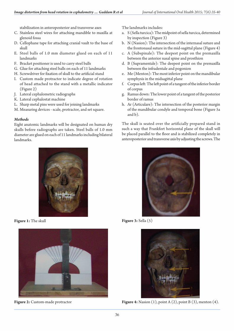
College, Davanagere on the basis of following parameters:a. Intact human skull and mandible (Figure 1)b. It should have no gross asymmetryc. I t should have permanent dentition in both upper
and lower arches of minimum up to maxillary and mandibular first molars
d. Sex, occlusion, and skeletal pattern were not significantly considered.
B. Artificially prepared stand for seating of skull and adjustments were made with screws for complete
36
Image distortion from head rotation in cephalometry … Gaddam R et al Journal of International Oral Health 2015; 7(6):35-40
stabilization in anteroposterior and transverse axesC. Stainless steel wires for attaching mandible to maxilla at
glenoid fossaD. Cellophane tape for attaching cranial vault to the base of
skullE. Steel balls of 1.0 mm diameter glued on each of 11
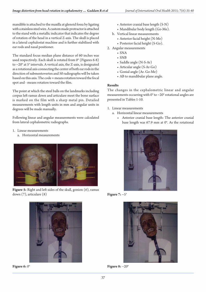
landmarksF. Bracket positioner is used to carry steel ballsG. Glue for attaching steel balls on each of 11 landmarksH. Screwdriver for fixation of skull to the artificial standI. Custom made protractor to indicate degree of rotation
of head attached to the stand with a metallic indicator (Figure 2)
J. Lateral cephalometric radiographsK. Lateral cephalostat machineL. Sharp metal pins were used for joining landmarksM. Measuring devices - scale, protractor, and set square.
MethodsEight anatomic landmarks will be designated on human dry skulls before radiographs are taken. Steel balls of 1.0 mm diameter are glued on each of 11 landmarks including bilateral landmarks.
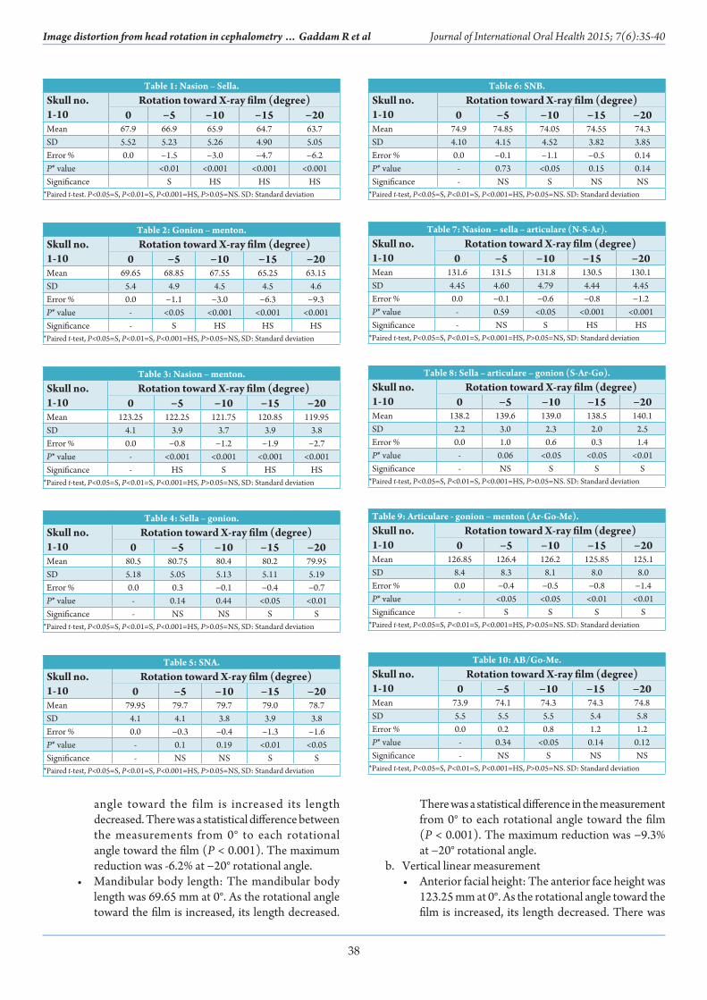
The landmarks includes:a. S (Sella turcica): The midpoint of sella turcica, determined
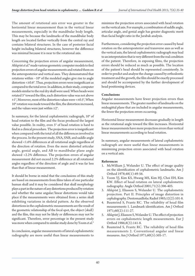
by inspection (Figure 3)b. N (Nasion): The intersection of the internasal suture and
the frontonasal suture in the mid-sagittal plane (Figure 4)c. A (Subspinale): The deepest point on the premaxilla
between the anterior nasal spine and prosthiond. B (Supramentale): The deepest point on the premaxilla
between the infradentale and pogonione. Me (Menton): The most inferior point on the mandibular
symphysis in the midsagittal planef. Corpus left: The left point of a tangent of the inferior border
of corpusg. Ramus down: The lower point of a tangent of the posterior
border of ramush. Ar (Articulare): The intersection of the posterior margin
of the mandibular condyle and temporal bone (Figure 5a and b).
The skull is seated over the artificially prepared stand in such a way that Frankfort horizontal plane of the skull will be placed parallel to the floor and is stabilized completely in anteroposterior and transverse axis by adjusting the screws. The
Figure 1: The skull
Figure 2: Custom-made protractor
Figure 3: Sella (5)
Figure 4: Nasion (1), point A (2), point B (3), menton (4).
37
Image distortion from head rotation in cephalometry … Gaddam R et al Journal of International Oral Health 2015; 7(6):35-40
mandible is attached to the maxilla at glenoid fossa by ligating with a stainless steel wire. A custom made protractor is attached to the stand with a metallic indicator that indicates the degree of rotation of the head in a vertical Z-axis. The skull is placed in a lateral cephalostat machine and is further stabilized with ear rods and nasal positioner.
The standard focus median plane distance of 60 inches was used respectively. Each skull is rotated from 0° (Figures 6-8) to −20° at 5° intervals. A vertical axis, the Z-axis, is designated as a rotational axis connecting the center of both ear rods in the direction of submentovertex and 50 radiographs will be taken based on this axis. The code + means rotation toward the focal spot and - means rotation toward the film.
The point at which the steel balls on the landmarks including corpus left ramus down and articulare meet the bone surface is marked on the film with a sharp metal pin. Detailed measurements with length units in mm and angular units in degrees will be made manually.
Following linear and angular measurements were calculated from lateral cephalometric radiographs.
1. Linear measurementsa. Horizontal measurements
• Anterior cranial base length (S-N) • Mandibular body length (Go-Me).b. Vertical linear measurements • Anterior facial height (N-Me) • Posterior facial height (S-Go).
2. Angular measurements • SNA • SNB • Saddle angle (N-S-Ar) • Articular angle (S-Ar-Go) • Gonial angle (Ar. Go-Me) • AB to mandibular plane angle.
ResultsThe changes in the cephalometric linear and angular measurements occurring with 0° to −20° rotational angles are presented in Tables 1-10.
1. Linear measurementsa. Horizontal linear measurements
• Anterior cranial base length: The anterior cranial base length was 67.9 mm at 0°. As the rotational
Figure 5: Right and left sides of the skull, gonion (6), ramus down (7), articulare (8)
Figure 6: 0°
Figure 7: −5°
Figure 8: −20°
38
Image distortion from head rotation in cephalometry … Gaddam R et al Journal of International Oral Health 2015; 7(6):35-40
angle toward the film is increased its length decreased. There was a statistical difference between the measurements from 0° to each rotational angle toward the film (P < 0.001). The maximum reduction was -6.2% at −20° rotational angle.
• Mandibular body length: The mandibular body length was 69.65 mm at 0°. As the rotational angle toward the film is increased, its length decreased.
There was a statistical difference in the measurement from 0° to each rotational angle toward the film (P < 0.001). The maximum reduction was −9.3% at −20° rotational angle.
b. Vertical linear measurement• Anterior facial height: The anterior face height was
123.25 mm at 0°. As the rotational angle toward the film is increased, its length decreased. There was
Table 1: Nasion – Sella.Skull no. 1‑10
Rotation toward X‑ray film (degree)0 −5 −10 −15 −20
Mean 67.9 66.9 65.9 64.7 63.7SD 5.52 5.23 5.26 4.90 5.05Error % 0.0 −1.5 −3.0 −4.7 −6.2P* value <0.01 <0.001 <0.001 <0.001Significance S HS HS HS
*Paired t-test. P<0.05=S, P<0.01=S, P<0.001=HS, P>0.05=NS. SD: Standard deviation
Table 2: Gonion – menton.Skull no. 1‑10
Rotation toward X‑ray film (degree)0 −5 −10 −15 −20
Mean 69.65 68.85 67.55 65.25 63.15SD 5.4 4.9 4.5 4.5 4.6Error % 0.0 −1.1 −3.0 −6.3 −9.3P* value - <0.05 <0.001 <0.001 <0.001Significance - S HS HS HS
*Paired t-test, P<0.05=S, P<0.01=S, P<0.001=HS, P>0.05=NS, SD: Standard deviation
Table 3: Nasion – menton.Skull no. 1‑10
Rotation toward X‑ray film (degree)0 −5 −10 −15 −20
Mean 123.25 122.25 121.75 120.85 119.95SD 4.1 3.9 3.7 3.9 3.8Error % 0.0 −0.8 −1.2 −1.9 −2.7P* value - <0.001 <0.001 <0.001 <0.001Significance - HS S HS HS
*Paired t-test, P<0.05=S, P<0.01=S, P<0.001=HS, P>0.05=NS, SD: Standard deviation
Table 4: Sella – gonion.Skull no. 1‑10
Rotation toward X‑ray film (degree)0 −5 −10 −15 −20
Mean 80.5 80.75 80.4 80.2 79.95SD 5.18 5.05 5.13 5.11 5.19Error % 0.0 0.3 −0.1 −0.4 −0.7P* value - 0.14 0.44 <0.05 <0.01Significance - NS NS S S
*Paired t-test, P<0.05=S, P<0.01=S, P<0.001=HS, P>0.05=NS, SD: Standard deviation
Table 5: SNA.Skull no. 1‑10
Rotation toward X‑ray film (degree)0 −5 −10 −15 −20
Mean 79.95 79.7 79.7 79.0 78.7SD 4.1 4.1 3.8 3.9 3.8Error % 0.0 −0.3 −0.4 −1.3 −1.6P* value - 0.1 0.19 <0.01 <0.05Significance - NS NS S S
*Paired t-test, P<0.05=S, P<0.01=S, P<0.001=HS, P>0.05=NS, SD: Standard deviation
Table 6: SNB.Skull no. 1‑10
Rotation toward X‑ray film (degree)0 −5 −10 −15 −20
Mean 74.9 74.85 74.05 74.55 74.3SD 4.10 4.15 4.52 3.82 3.85Error % 0.0 −0.1 −1.1 −0.5 0.14P* value - 0.73 <0.05 0.15 0.14Significance - NS S NS NS
*Paired t-test, P<0.05=S, P<0.01=S, P<0.001=HS, P>0.05=NS. SD: Standard deviation
Table 7: Nasion – sella – articulare (N‑S‑Ar).Skull no. 1‑10
Rotation toward X‑ray film (degree)0 −5 −10 −15 −20
Mean 131.6 131.5 131.8 130.5 130.1SD 4.45 4.60 4.79 4.44 4.45Error % 0.0 −0.1 −0.6 −0.8 −1.2P* value - 0.59 <0.05 <0.001 <0.001Significance - NS S HS HS
*Paired t-test, P<0.05=S, P<0.01=S, P<0.001=HS, P>0.05=NS, SD: Standard deviation
Table 8: Sella – articulare – gonion (S‑Ar‑Go).Skull no. 1‑10
Rotation toward X‑ray film (degree)0 −5 −10 −15 −20
Mean 138.2 139.6 139.0 138.5 140.1SD 2.2 3.0 2.3 2.0 2.5Error % 0.0 1.0 0.6 0.3 1.4P* value - 0.06 <0.05 <0.05 <0.01Significance - NS S S S
*Paired t-test, P<0.05=S, P<0.01=S, P<0.001=HS, P>0.05=NS. SD: Standard deviation
Table 9: Articulare ‑ gonion – menton (Ar‑Go‑Me).Skull no. 1‑10
Rotation toward X‑ray film (degree)0 −5 −10 −15 −20
Mean 126.85 126.4 126.2 125.85 125.1SD 8.4 8.3 8.1 8.0 8.0Error % 0.0 −0.4 −0.5 −0.8 −1.4P* value - <0.05 <0.05 <0.01 <0.01Significance - S S S S
*Paired t-test, P<0.05=S, P<0.01=S, P<0.001=HS, P>0.05=NS. SD: Standard deviation
Table 10: AB/Go‑Me.Skull no. 1‑10
Rotation toward X‑ray film (degree)0 −5 −10 −15 −20
Mean 73.9 74.1 74.3 74.3 74.8SD 5.5 5.5 5.5 5.4 5.8Error % 0.0 0.2 0.8 1.2 1.2P* value - 0.34 <0.05 0.14 0.12Significance - NS S NS NS
*Paired t-test, P<0.05=S, P<0.01=S, P<0.001=HS, P>0.05=NS. SD: Standard deviation

39
Image distortion from head rotation in cephalometry … Gaddam R et al Journal of International Oral Health 2015; 7(6):35-40
statistical difference in the measurement from 0° to each rotational angle toward film (P < 0.001)
• Posterior facial height: The posterior facial height was 80.15 mm at 0°. There was no statistical difference in the measurement from 0° to −10° (P > 0.4) whereas the statistical difference was found in the measurement at −15°, −20° (P < 0.005). The difference was <0.7% from 0° to −20°.
2. Angular measurements• SNA: SNA was 79.95° at 0°. There was a statistical
difference in the measurement at −15° and −20° rotational angle toward the film (P < 0.05). The maximum reduction was −1.6% at −20° rotational angle
• SNB: SNB was 74.9° at 0°. Statistical difference was found in the measurements at −10° angulation toward X-ray film. The difference was <0.8% from 0° to each rotational angle toward X-ray film
• Saddle angle: The saddle angle was 131.6° at 0°. There was statistical difference found in the measurement at −10°, −15°, −20° (P < 0.001) rotational angles toward X-ray film. The maximum reduction was −1.2% at −20° rotational angle
• Articular angle: The articular angle was 138.20° at 0°. There was a statistical difference in the measurement at −10° rotational angle (P < 0.05) toward X-ray film. The difference was <1.5% from 0° to each rotational angle toward X-ray film
• Gonial angle: The gonial angle was 126.85° at 0°. There was a statistical difference in the measurement at −5° rotational angle (P < 0.05) toward X-ray film. The difference was <1.5% from 0° to each rotational angle toward X-ray film
• AB to mandibular plane angle: AB to mandibular plane angle was 73.9° at 0°. There was no statistical difference in the measurements from 0° to each rotational angle toward the film (P < 0.5) except at −10° rotational angle (P < 0.05). The difference was <2.2% from 0° to each rotational angle toward X-ray film.
DiscussionHead rotation can occur in the anteroposterior axis, vertical axis, and transverse axis. However, standardization on the anteroposterior and transverse axes is actually hard to achieve. Rotation on the transverse axis causes no distortion of images. Although the head rotates on the transverse axis, the location of head is parallel to the central ray, only the location of images on the film changes, but this does not cause a change of relationship between land marks.3 However, rotation in the anteroposterior axis affects landmarks vertically, not horizontally. The bilateral structures are moved equally and the vertical distance between landmarks changes depending on the distances of landmarks from the rotation axis.4
Rotation on the vertical axis influenced the horizontal measurements, not the vertical measurement, in a different manner from rotation on the anteroposterior axis. Unless landmarks are located equidistance from the midsagittal plane, any rotation on the axis changes the relationship between the midsagittal line and bilateral landmarks. Therefore, bilateral landmarks are equally placed against the midsagittal plane within the skull should be measured to remove adverse effects of rotation on the vertical axis.5
A major source of random errors in cephalometric investigations is usually the identification of landmarks. This source of error was markedly reduced in the present study, due to the availability of placed sets of metallic markers (steel balls of 1.0 mm diameter) at the defined anthropometric points.
In the present study, the measurement values are different according to the direction of rotation because different planes have different magnification with different ratios.
Concerning projection errors of linear measurement, Ahlqvist et al.6 supposed that the effects of rotations on the anteroposterior and vertical axis may be identical. In their study using a computer model similar to the real dry skull, they found that rotation of ±5° from the ideal position resulted in errors of <1%, a margin that is usually insignificant and difficult to distinguish from other errors. However, the errors became significant at even a few degrees of rotation more than ±5°. The projection error of the present study was different depending on the direction of rotation, contrary to the results of Ahlqvist et al.6
The anterior cranial base length and mandibular body length gradually decreased as the rotational angle toward the film increased. There was a statistical difference in the measurements from 0° to each rotational angle toward the film in the anterior cranial base length (P < 0.001). The difference and above −1.5% in the anterior cranial base length, −1.1% in mandibular body length with an increase of more than −5° rotational angle, and the maximum reduction was −6.2% in the anterior cranial base length and −9.3% in the mandibular body length at −20° rotational angle. These were the same as the results of Ahlqvist et al.6 and Yoom et al.2 This is thought to result because the nearer to the film the head rotates, the more the image decreases and this decrease is gradual because the rotation itself causes the decrease of images.
In the anterior facial height, there was a statistical difference in the measurement from 0° to each rotational angle toward the film (P < 0.001). The difference was <2.7% at −20° rotational angle. In posterior facial height, the difference was <1.6%. The variation due to head rotation was the least among all the linear measurements.
40
Image distortion from head rotation in cephalometry … Gaddam R et al Journal of International Oral Health 2015; 7(6):35-40
The amount of rotational axis error was greater in the horizontal linear measurement than in the vertical linear measurements, especially in the mandibular body length. This may be because the landmarks of the mandibular body length are located farther vertically from the central ray and contains bilateral structures. In the case of posterior facial height including bilateral structures, however the difference was minimal because it is near to the rotational axis.
Concerning the projection errors of angular measurement, Ahlqvist et al.6 made various geometric computer models to find projection errors of angular measurements and rotated them on the anteroposterior and vertical axes. They demonstrated that rotations within −10° of the modeled angles give rise to angle distortion <±0.6°. Thus, projection errors were insignificant as compared to the total error. In addition, in their study, computer models similar to the real dry skull were used. When heads were rotated 5° toward the film, each distortion value was not above ±1°, Moreover, most of the distortion values were <±0.5°, When 10° rotation was made toward the film, the distortion increased, and the values were just within ±2°.
In summary, for the lateral cephalometric radiograph, 10° of head rotation to the film and the focus produced the largest value possible. In reality, even 5° of head rotation is hard to find in a clinical procedure. The projection error is insignificant when compared with the total of all the differences involved in the process. In the present study, SNA, SNB, and saddle angle showed <1.6% differences at all rotational angle regardless of the direction of rotation. Even the more distorted articular angle, gonial angle, and AB to mandibular plane angle showed <2.2% difference. The projection errors of angular measurement did not exceed 2.2% difference at all rotational angles regardless of the direction of angle and it was far less than that of linear measurement.
It should be borne in mind that the conclusions of this study are based on measurements from films taken of one particular human skull and it may be considered that skull morphology plays a part in the nature of any distortions produced by rotation and whether the same angular/linear distortions would take place if the measurements were obtained from a series skull exhibiting variations in skeletal pattern. As the observed distortions in the cephalometric measurements are the result of the geometric relationship of the focal spot, the object (skull) and the film, this may not be likely or differences may not be significant. Therefore, error percentage in the present study was more when compared to similar study done by Yoom et al.2
In conclusion, angular measurements of lateral cephalometric radiography are more useful than linear measurements to
minimize the projection errors associated with head rotation on the vertical axis. For example, a combination of saddle angle, articular angle, and gonial angle has greater diagnostic merit than facial height ratio in the Jarabak analysis.
Furthermore, considering the projection error caused by head rotation on the anteroposterior and transverse axes as well as the vertical axis, the lateral cephalometric radiograph may lead to an interpretation that is very different from the real condition of the patient. Therefore, in exposing films, the projection errors should be reduced as much as possible. The location of the patient’s head should be represented consistently. In order to predict and analyze the change caused by orthodontic treatment and the growth, the film should be exactly processed and should be accompanied by the further development of head positioning devices.
ConclusionsAngular measurements have fewer projection errors than linear measurements. The greater number of landmarks on the midsagittal plane that are included in angular measurements, the fewer the projection errors occurring.
Horizontal linear measurement decreases gradually in length as the rotational angle toward the film increases. Horizontal linear measurements have more projection errors than vertical linear measurements according to head rotation.
In summary, angular measurements of lateral cephalometric radiograph are more useful than linear measurements in minimizing projection errors associated with head rotation on a vertical axis.
References1. McWilliam J, Welander U. The effect of image quality
on the identification of cephalometric landmarks. Am J Orthod 1978;48(1):49-56.
2. Yoom YJ, Kim KS, Hwang MS, Kim HJ, Choi EH, Kim KW. Effect of head rotation on lateral cephalometric radiography. Angle Orthod 2001;71(5):396-403.
3. Ahlqvist J, Eliasson S, Welander U. The cephalometric projection. Part II. Principles of image distortion in cephalography. Dentomaxillofac Radiol 1983;12(2):101-8.
4. Baumrind S, Frantz RC. The reliability of head film measurements 1. Landmark identification. Am J Orthod 1971;60(2):111-27.
5. Ahlqvist J, Eliasson S, Welander U. The effect of projection errors on cephalometric length measurements. Eur J Orthod 1986;8(3):141-8.
6. Baumrind S, Frantz RC. The reliability of head film measurements 2. Conventional angular and linear measures. Am J Orthod 1971;60(5):505-17.