Assessment of Full Width Deformable Barrier test and CAE...
15
Assessment of Full Width Deformable Barrier test and CAE simulations for vehicle compatibility - Development of software to evaluate, animate, interrogate and compare both test and CAE data - Dr. Coulton, Jerome Kim, Nam Yong Dr. Shin, Jangho Ebeling, Matthias Hyundai Motor, Europe Hyundai Motor, Europe Hyundai Motor, Company Altair . ABSTRACT Vehicle compatibility is on the Euro-NCAP road map and has been the subject for research by both in Europe (VC-COMPAT) and the USA (NHTSA). This presentation details the development of an automated method to assess and compare test and CAE data with respect to the proposed Full Width Deformable Barrier test defined by European Enhanced Vehicle Safety Committee Working Group 15 and also the Full Width Rigid Barrier (with high resolution load cell wall) by NHTSA. The output of the project was a fully interactive HyperWorks plug-in which allows the user to animate, interrogate and compare both test and CAE data. European HTC 2009 , Ludwigsburg, 2 nd –4 th November 2009 Hyundai Motor Europe Technical Center GmbH Rüsselsheim www.hyundai-europe.com
Transcript of Assessment of Full Width Deformable Barrier test and CAE...

Assessment of Full Width Deformable Barriertest and CAE simulations for vehicle compatibility
- Development of software to evaluate, animate, interrogate and compareboth test and CAE data -
Prepared by : Dr. Coulton
Dr. Coulton, Jerome Kim, Nam Yong Dr. Shin, Jangho Ebeling, MatthiasHyundai Motor, Europe Hyundai Motor, Europe Hyundai Motor, Company Altair .
ABSTRACTVehicle compatibility is on the Euro-NCAP road map and has been the subject for research by both in Europe (VC-COMPAT) and the USA (NHTSA). This presentation details the development of an automated method to
assess and compare test and CAE data with respect to the proposed Full Width Deformable Barrier test defined by European Enhanced Vehicle Safety Committee Working Group 15 and also the Full Width Rigid Barrier (with
high resolution load cell wall) by NHTSA. The output of the project was a fully interactive HyperWorks plug-in which allows the user to animate, interrogate and compare both test and CAE data.
European HTC 2009 , Ludwigsburg, 2nd – 4th November 2009
Hyundai Motor Europe Technical Center GmbHRüsselsheim
www.hyundai-europe.com

2
Hyundai Motor Europe Tech. Center GmbH
• Introduction to Vehicle Compatibility
– Linkage between Occupant and Partner Protection
– Partner Protection Test and Metric Data Set
– Evaluation Metrics for Partner Protection
• Software Development
– Hyundai Barrier Evaluation Tool Requirements
– Input Data
– User Interface
• Output
– Full Width Rigid Barrier
– Full Width Deformable Barrier
– Animation of Forces and Vehicle Simulation
• Software Key Points
• Conclusions
Contents

3
Hyundai Motor Europe Tech. Center GmbH
• The first vehicle compatibility agreement has been voluntarily committed to for the North American Market by the Alliance of Automobile Manufacturers in 2003 for implementation in 2009.
• The European Union funded a study into compatibility which completed in 2006. “Improvement of Vehicle Crash Compatibility through the Development of Crash Test Procedures (VC-COMPAT)”
• The protection of occupants in the colliding vehicles (partner protection) is on the Euro-NCAP road map (2014)
Introduction to Vehicle Compatibility

4
Hyundai Motor Europe Tech. Center GmbHLinkage between Occupant and Partner Protection
Occupant PartnerU
S N
CAP
IIHS
JN N
CAP
Euro
NC
AP
FWC
B64
OD
B80
OD
B60
PD
B+ LCW+ new barrier+ new speed
+ LCW+ high speed
+ LCW
+ LCW+ new barrier
+ LCW
EEVC
WG
15
NH
TSA
56 Km/h
64 Km/h
56 Km/h
80 Km/h
60 Km/h
Rigid Wall Standard Barrier Load cells New Barrier

5
Hyundai Motor Europe Tech. Center GmbHPartner Protection Test and Metric Data Set
Test configuration
FWC
B64
OD
B80
OD
B60
PD
B+ LCW+ new barrier+ new speed
+ LCW+ high speed
+ LCW
+ LCW+ new barrier
+ LCW
NH
TSA
56 Km/h
64 Km/h
56 Km/h
80 Km/h
60 Km/h
Barrier force Fmax (Peak Total Load Cell Wall Force)HoF400 (Height of Force )AHoF400 (Height of Force @ 400 mm displacement)KW400 (Crush work stiffness @ 400 mm displacement)F3 (Σpeak forces in row 3)F4 (Σpeak forces in row 4)F340 (Σpeak forces in row 3, < 40ms)F440, (Σpeak forces in row 4, < 40ms)
Barrier displacement
Barrier force Fmax (Peak Total Load Cell Wall Force)VSI (Area 1) (Vertical structural interaction)VSI (Area 2) (Vertical structural interaction)HSI (Area 1) (Horizontal structural interaction)HSI (Area 1 + outer support) (Horizontal structural interaction)HSI (Area 2) (Horizontal structural interaction)HSI (Area 2 + outer support) (Horizontal structural interaction)
Barrier displacement
Barrier force Fmax (Peak Total Load Cell Wall Force)RHcl (Overall (Cell) relative homogeneity criterion)RHr (Vertical (Row) relative homogeneity criterion)RHc (Horizontal (Column) relative homogeneity criterion)RH0 (Total relative homogeneity criterion)
Barrier displacement
Barrier force Record and monitorBarrier displacement
Barrier force Fmax (Peak Total Load Cell Wall Force)Barrier displacement PPAD (Partner protectionassessment of deformation)
ADoD (Average depth of deformation)AHoD (Average height of Deformation)Dmax (Maximum depth of Deformation)Z(Dmax) (Height of maximum depth of Deformation)Volume (Volume of deformation)Energy (Energy of deformation)
Not defined
TRL V3.0 Mar 2007
NHTSA
PDB V2.3 Feb 2006
TRL V1.6 Feb 2006
Metrics
Obsolete
Ord
er o
f Im
porta
nce
No
Metrics
Software
Exists
No
Metrics

6
Hyundai Motor Europe Tech. Center GmbHEvaluation Metrics for Partner Protection
• There are two different types of metrics that could be used for partner protection:– Barrier force– Barrier deformation
• As well as assessing partner protection, occupant protection evaluation is also proposed:– BiW deformation– Occupant injury
• At present there is no standard software for assessing barrier forces for partner protection.
• This was the motivation for developing the “Hyundai Barrier Evaluation Tool”.
7
Hyundai Motor Europe Tech. Center GmbH
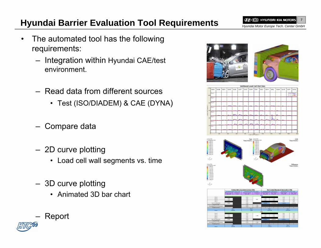
• The automated tool has the following requirements:– Integration within Hyundai CAE/test
environment.
– Read data from different sources• Test (ISO/DIADEM) & CAE (DYNA)
– Compare data
– 2D curve plotting• Load cell wall segments vs. time
– 3D curve plotting• Animated 3D bar chart
– Report
Hyundai Barrier Evaluation Tool Requirements
TEST

8
Hyundai Motor Europe Tech. Center GmbHInput Data
• CAE/Test Data from both vehicle and barrier are required:– Vehicle
• Vehicle acceleration.• Identified by node number, ISO
tag “BPIL” or NHTSA tag “BPLR”
– Barrier• LCW forces.• Identified by channel code or
Rigidwall segment number.
9
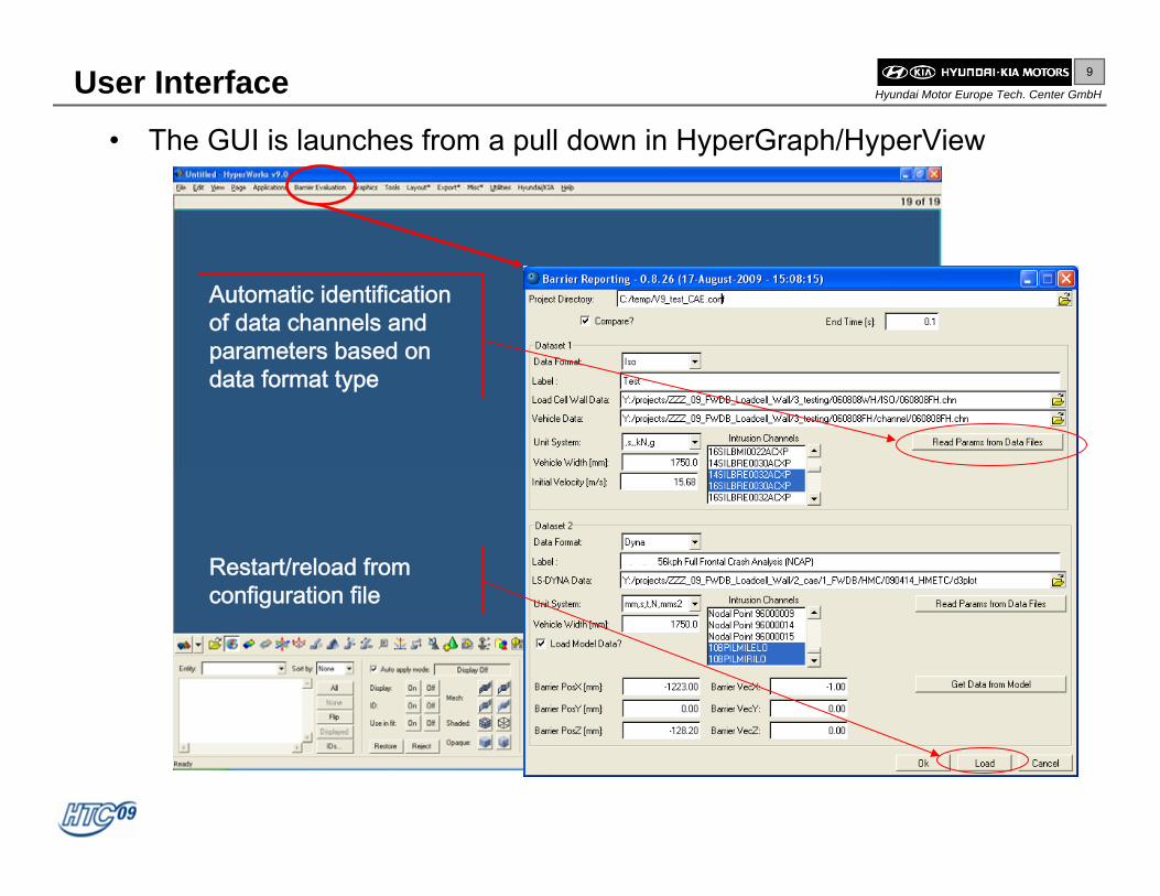
Hyundai Motor Europe Tech. Center GmbHUser Interface
• The GUI is launches from a pull down in HyperGraph/HyperView
Automatic identification of data channels and parameters based on data format type
Restart/reload from configuration file

10
Hyundai Motor Europe Tech. Center GmbH
• Following the processing of the data, the software generates a table with the necessary metrics.
• The corresponding 2-D charts to enable their interpretation are also created:– Filtered and unfiltered load cell
wall data– AVS Diagram– Total load cell wall forces– Row 3 and row 4 forces– Height of forces– Crush work Stiffness & energy
Full Width Rigid Barrier (US-NCAP)
Metric Name Limits
AHOF40 406-508mm Ftotal Peak >350 kNF3 Peak >100kN F3(40) >100kN F4 Peak >100kN F4(40) >100kN
Initial Velocity 17.61-18.15m/sAHoF(400) 406-508mm F3(400) >100kN F4(400) >100kN Kw400 1300-1700N/mm
Time Dependent Metrics
Displacement Dependent Metrics15.278 - 15.834 m/S

11
Hyundai Motor Europe Tech. Center GmbH
• Following the processing of the data, the software generates a table with the necessary metrics.
• The corresponding 2-D charts to enable their interpretation are also created:– Filtered and unfiltered load cell
wall data– TRL Target row loads– TRL Target cell loads– Peak load cell forces (rows 2
to 5)– Negative deviations (rows 2 to
5)
Full Width Deformable Barrier

12
Hyundai Motor Europe Tech. Center GmbH
HyperView Player H3D
Animation of Forces and Vehicle Simulation• The forces can be animated allowing the user to visualize the load
distribution.• The load cell wall forces can be animated and manipulated in 3 dimensions
just like a 3-D CAE model

13
Hyundai Motor Europe Tech. Center GmbH
• As the software has been created as a HyperWorks plug-in it will work on multiple platforms.
• The software has been tested under the following conditions:– HyperWorks versions 9 &10– Windows XP (32 & 64 bit)– LINUX (Redhat)
• The use of a configuration file allows the user to reload all necessary data:– location of input files– location of output files– location of results– Evaluation parameters
• All current metrics for FWRD and FWDB are automatically evaluated and exported in a standardized format (.htm file).
Hyundai Barrier Evaluation Software, Key Points

14
Hyundai Motor Europe Tech. Center GmbHConclusions
• A new software tool for the evaluation of FWRB and FWDB data was successfully developed (Hyundai Barrier Evaluation Tool).
• Both test and simulation data sets can be read in and compared using a single software tool.
• Through the ability to animate the results in 3 dimensions and review the differences between data sets, the user is able to rapidly identify and understand the root causes for the resultant metricvalues or changes in their values when comparing data sets.
• The Hyundai Barrier Evaluation Tool can help address three majoraspects of vehicle front ends for vehicle compatibility:– Geometry;– Stiffness;– Energy absorbance.

15
Hyundai Motor Europe Tech. Center GmbHReferences
1. Public Citizen, Keeping the Safety in SAFETEA: Life-Saving Vehicle Safety Provisions Are Long-Overdue and Feasible, March 2004, retrieved from www.citizen.org
2. European Enhanced Vehicle-safety Committee Working Group 15, Car Crash Compatibility and Frontal Impact - Final Report to Steering Committee, May 2007, retrieved from wg15.eevc.org
3. NHTSA, A Report on Voluntary Industry Effort to Further Enhance Front to Front Vehicle Crash Compatibility (DRAFT), 11-12-08.
4. Van Ratingen, Summary Presentation, APROSYS Final Event, 17/18 February 2009, retrieved from www.aprosys.com
5. KIA joins in voluntary commitment to enhance vehicle safety, 4 December 2003, retrieved from www.kiamedia.com
6. European Transport Safety Council, Assessing risk and setting targets in transport safety programmes, 2003, Brussels, retrieved from www.etsc.eu.
7. European Road Safety Observatory (2006), Vehicle Safety, 10 August 2007, retrieved from www.erso.eu
8. P Mohan & D Smith, Finite element analysis of compatibility metrics in frontal collisions, June 2007, 20th ESV Conference, retrieved from www.nhtsa.dot.gov
9. H Yonezawa et al, Summary of Activities of the Compatibility Working Group in Japan, June 2009, 21st ESV Conference, retrieved from www.nhtsa.dot.gov
10. M Edwards et al., Improvement of Vehicle Crash Compatibility through the Development of Crash Test Procedures, Final Report – VC-COMPAT Project GRD2/2001/50083, retrieved from vc-compat.rtdproject.net
![EVALUATION OF MOVING PROGRESSIVE DEFORMABLE BARRIER … · several mass-production vehicles [3]. Figure 4. Advanced Compatibility Engineering Structure. ADAC currently recommends](https://static.fdocuments.us/doc/165x107/5e8efd24521e83248f376f84/evaluation-of-moving-progressive-deformable-barrier-several-mass-production-vehicles.jpg)


![Variational Context-Deformable ConvNets for Indoor Scene ... Variational Context-Deformable... · Deformable ConvNets v2 [56] reformulated DCN with mask weights, which alleviated](https://static.fdocuments.us/doc/165x107/5f26bf72421c4b2b0840bb0e/variational-context-deformable-convnets-for-indoor-scene-variational-context-deformable.jpg)