Assessment of Bearing Dynamic Characteristics by Numerical ...
14
Research Article Assessment of Bearing Dynamic Characteristics by Numerical Modeling with Effects of Oil Film and Centrifugal Deformation Jie Yu, 1,2 Wei Yuan, 2 Songsheng Li , 1 and Wenbing Yao 3 Shanghai Key Laboratory of Mechanical Automation and Robotics, Shanghai University, Shanghai , China School of Mechanical Engineering, Shandong University of Technology, Zibo , China Jude Construction and Installation Co., Ltd., Zibo, Shandong , China Correspondence should be addressed to Songsheng Li; [email protected] Received 24 April 2018; Revised 30 August 2018; Accepted 22 October 2018; Published 6 November 2018 Academic Editor: Anders Eriksson Copyright © 2018 Jie Yu et al. is is an open access article distributed under the Creative Commons Attribution License, which permits unrestricted use, distribution, and reproduction in any medium, provided the original work is properly cited. is paper developed a modified quasi-static model (MQSM), considering the oil film thickness between the bearing parts and the centrifugal deformation of the inner ring, and contrasting with traditional quasi-static model (TQSM), to analyze the dynamic characteristics of spindle bearing. e model was verified with the experimental results. A systematic parametric analysis was made to investigate the influence of applied load, inner ring rotation speed (ni), and the radius coefficient of groove curvature (RCR) on the contact load, contact angle, and heat generating rate. e results show that there is a smaller influence on the contact load, contact angle, and heat generation of bearing with the changes of ni and axial load ( ) of bearing in the case of MQSM and TQSM. But the radial load ( ) and RCR have great influence on this. 1. Introduction Kinematic accuracy of the main shaſts commonly determines the machining quality, performance, service life, and relia- bility of high-speed machine tool, in which the supporting spindle bearings play a very important role [1, 2]. e higher speed and reliability of spindle bearings subjected to the continuously large thrust loading are demanded during high rotational speed machining. erefore, it is necessary to create an accurate model to reflect the dynamic characteris- tics of spindle bearings, including rotational speed, contact temperature, and dynamic loading [3–6]. Especially, the oil film thickness and inner ring centrifugal deformation should be taken into account for the assessments of the spindle bearings’ dynamic characteristics, which may significantly affect the geometry relationship of the bearing internal channel curvature center and the ball center obviously. It was found that the centrifugal expansion deformation of the bearing inner ring is much larger than the deformation of the shaſt with the increase of rotational speed. Based on a dynamic model of spindle bearings, the research of Cao et al. [7] indicated that the bearing contact angle decreases with the increase of contact load by introducing the centrifugal expansion deformation of the bearing inner ring. e general spindle bearing FEM [8] showed that the impact factors of high-speed system, such as bearing radial stiffness, centrifu- gal force, and gyroscopic moments, have a significant effect on dynamic characteristics of spindle system in high speeds. A coupled spindle bearing model was established considering the centrifugal deformation by Hong et al. [9], and the simulation and experimental results indicated that there is a correlation between the natural frequency and the number of bearings. e Jones’ bearing model was updated by Guo et al. [10], by considering of radial centrifugal expansion and thermal deformations on the geometric displacement in the bearings, which can predict the contact angle, deformation, and load between rolling elements and bearing raceways more accurately. During the high rotating process of the spindle bearings, lubrication oil film can also bear a part of multiple orientation loading, which plays significantly important roles in the dynamic characteristics and the distance between the bearing internal channel curvature center and the ball center [11–14]. e shear of oil film will cause remarkable heat of hydrostatic Hindawi Mathematical Problems in Engineering Volume 2018, Article ID 1619297, 13 pages https://doi.org/10.1155/2018/1619297
Transcript of Assessment of Bearing Dynamic Characteristics by Numerical ...

Research ArticleAssessment of Bearing Dynamic Characteristics by NumericalModeling with Effects of Oil Film and Centrifugal Deformation
Jie Yu12 Wei Yuan2 Songsheng Li 1 andWenbing Yao3
1Shanghai Key Laboratory of Mechanical Automation and Robotics Shanghai University Shanghai 200072 China2School of Mechanical Engineering Shandong University of Technology Zibo 255049 China3Jude Construction and Installation Co Ltd Zibo Shandong 255000 China
Correspondence should be addressed to Songsheng Li 03810020shueducn
Received 24 April 2018 Revised 30 August 2018 Accepted 22 October 2018 Published 6 November 2018
Academic Editor Anders Eriksson
Copyright copy 2018 Jie Yu et al This is an open access article distributed under the Creative Commons Attribution License whichpermits unrestricted use distribution and reproduction in any medium provided the original work is properly cited
This paper developed a modified quasi-static model (MQSM) considering the oil film thickness between the bearing parts andthe centrifugal deformation of the inner ring and contrasting with traditional quasi-static model (TQSM) to analyze the dynamiccharacteristics of spindle bearingThemodel was verified with the experimental results A systematic parametric analysis wasmadeto investigate the influence of applied load inner ring rotation speed (ni) and the radius coefficient of groove curvature (RCR) onthe contact load contact angle and heat generating rate The results show that there is a smaller influence on the contact loadcontact angle and heat generation of bearing with the changes of ni and axial load (119865119886) of bearing in the case of MQSM and TQSMBut the radial load (119865119903) and RCR have great influence on this
1 Introduction
Kinematic accuracy of the main shafts commonly determinesthe machining quality performance service life and relia-bility of high-speed machine tool in which the supportingspindle bearings play a very important role [1 2] The higherspeed and reliability of spindle bearings subjected to thecontinuously large thrust loading are demanded during highrotational speed machining Therefore it is necessary tocreate an accurate model to reflect the dynamic characteris-tics of spindle bearings including rotational speed contacttemperature and dynamic loading [3ndash6] Especially the oilfilm thickness and inner ring centrifugal deformation shouldbe taken into account for the assessments of the spindlebearingsrsquo dynamic characteristics which may significantlyaffect the geometry relationship of the bearing internalchannel curvature center and the ball center obviously
It was found that the centrifugal expansion deformationof the bearing inner ring is much larger than the deformationof the shaft with the increase of rotational speed Based ona dynamic model of spindle bearings the research of Cao etal [7] indicated that the bearing contact angle decreases with
the increase of contact load by introducing the centrifugalexpansion deformation of the bearing inner ringThe generalspindle bearing FEM [8] showed that the impact factors ofhigh-speed system such as bearing radial stiffness centrifu-gal force and gyroscopic moments have a significant effecton dynamic characteristics of spindle system in high speedsA coupled spindle bearing modelwas established consideringthe centrifugal deformation by Hong et al [9] and thesimulation and experimental results indicated that there is acorrelation between the natural frequency and the numberof bearings The Jonesrsquo bearing model was updated by Guoet al [10] by considering of radial centrifugal expansion andthermal deformations on the geometric displacement in thebearings which can predict the contact angle deformationand load between rolling elements and bearing racewaysmore accurately
During the high rotating process of the spindle bearingslubrication oil film can also bear a part ofmultiple orientationloading which plays significantly important roles in thedynamic characteristics and the distance between the bearinginternal channel curvature center and the ball center [11ndash14]The shear of oil film will cause remarkable heat of hydrostatic
HindawiMathematical Problems in EngineeringVolume 2018 Article ID 1619297 13 pageshttpsdoiorg10115520181619297
2 Mathematical Problems in Engineering
hydrodynamic hybrid bearings which will lead to decreasingof bearing clearance and even seizure especially at highrotational speed [15] An integrated thermal model [16] wasnumerically established to calculate the heat generation ofspindle bearings and temperature distribution of the spindlesystem considering the rotation speed preload and oil filmthickness Therefore the machine performance and dynamicdesign of machine spindle can be improved by taking intoaccount the impact of oil film thickness
To analyze the bearing dynamic characteristics the typ-ical quasi-statics modeling of spindle bearings was widelyutilized A five degrees of freedom quasi-static model of ballbearing under nonuniform preload was established by Li etal [17] and the results indicated that proper nonuniformpreload can improve the contact status between balls andrings and can also reduce the heat generation rate and theexcessive local heat in ball bearing under practical workingconditions Kim et al [18] employed the quasi-static analysismodel by taking dynamic effects into account to optimize thenonstandard angular contact ball bearing for the main shaftof a grinder The fatigue life calculations in rolling bearingsimulations were evaluated by a new quasi-static multidegreeof freedom tapered roller bearing model by considering non-Hertz contact pressures in time-domain simulations [19]However the assessment of the dynamic characteristics of thecontact load contact angle and bearing heatwith the increaseof rotational speed axial load radial load and coefficient ofraceway curvature radius (RCR) had not taken into accountboth the factors of film oil thickness and centrifugal defor-mation Therefore the establishment of considering boththe deformation of film thickness and centrifugal bearingmechanics model is extraordinarily important for a moreaccurate analysis of the dynamic characteristics of the spindlebearings
In this paper a modified quasi-statics model (MQSM)was established by considering the influence of film thicknessand centrifugal deformation which is expected to makethe bearing dynamic performance analysis more effectiveSection 2 showed the calculation algorithms of the deforma-tion of inner rings and rotors with the effect of film thicknessand centrifugal expansion deformation The MQSM wasestablished in Section 3 by considering film thickness andcentrifugal expansion deformation to reflect spindle bear-ingsrsquo dynamic characteristics The spindle bearing heat wasapplied as the comparison parameter with the experimentalresults the calculation of which was shown in Section 4The experimental and MQSM results in Section 5 were givenand discussed to reveal the changing rule of the dynamiccharacteristic parameters of the spindle bearings Section 6presented the concluding remarks
2 Deformation of Inner Ring and Rotor
21 Introducing Centrifugal Expansion Deformation Thecentrifugal force of bearing inner rings can hardly be ignoredand will result in centrifugal expansion deformation partic-ularly in high rotational speed On the basis of the elasticmechanics theory the bearing inner rings and the cooperat-ing rotating shafts are simplified in advance as the thin-walled
rings and the thick walled cylinder respectively Thereaftercentrifugal expansion deformation calculation formula canbe deduced at the coordination position of the shaft and theinner ring by (1) and (2) [7]
119906119888119904 =120588119904120596211989416119864119904 [(3 + ]119904) 1198892119904 + (1 minus ]119904) 1198893] 119889 (1)
119906119888119894 =120588119894120596211989416119864119894 [(3 + ]119894) 1198892 + (1 minus ]119894) 1198892119894 ] 119889119894 (2)
where 119906119888119904 is the centrifugal expansion deformation of shafts120588119904 ]119904 and 119864119904 are the density poison ratio and elasticitymodulus of the shaft respectively 119889119904 is the inner diameterof the spindle 119906119888119894 is the centrifugal expansion deformationof the inner ring 120588119894 ]119894 and 119864119894 are the density poison ratioand elasticity modulus of inner ring respectively 120596119894 is theangular speed of inner ring d and 119889119894 are the inner diametersof the inner ring and its channel respectively
The mutual interference fit coupling and constraintsamong the inner ring and shaft have frequently occurredwhereas the centrifugal expansion of the inner ring diameterand rotor outer diameter can reduce the amount of interfer-ence on fit surfaces when subjected to centrifugal force Themagnitude of interference caused by centrifugal expansion ofthe shaft and the inner ring can thus be determined as
119868119888 = 119906119888119894 minus 119906119888119904 (3)
As known centrifugal force deformation is proportionalto the square of the rotating speed and the centrifugal forcedeformation mainly occurred on the inner ring on thematingsurfaces of the shaft and the inner ring with the rotationalspeed increase The shaft centrifugal expansion deformationhas less effect on the change of bearing radial internalclearance Thereby the factor of the centrifugal expansiondeformation of the inner rings will be merely taken intoaccount to research the impact of the centrifugal expansiondeformation of the inner rings and shafts on the bearinginternal geometry relationship
22 Introducing Oil Film ickness Lubrication conditionplays remarkable role in spindle bearings therefore certainthickness of oil film between ring channels should be recom-mended Based on the theory of elastic hydrodynamic lubri-cation (EHL) oil film stiffness is determined by theminimumoil film thickness Under the condition of isothermal and ade-quate oil supply dimensionless center oil film thickness 119867119900and dimensionless minimum oil film thickness119867119898119894119899 betweenrolling body and ring channel can be determined as [11]
1198670 = 269119880067119866053119882minus0067 (1 minus 061119890minus073119896)119867min = 363119880068119866049119882minus0073 (1 minus 119890minus068119896)
(4)
where 119880 is the dimensionless velocity parameters 119866 is thedimensionless material parameters 119882 is the dimensionlessload parameters k is the ellipticity Thereafter center oil film
Mathematical Problems in Engineering 3
thickness ℎ0 and minimum oil film thickness 119867119898119894119899 betweenthe rolling body and ring channel are then determined as
ℎ0 = 1198771199091198670= 269119880067119866053119882minus0067 (1 minus 061119890minus073119896) 119877119909
ℎmin = 119877119909119867min
= 363119880068119866049119882minus0073 (1 minus 119890minus068119896)119877119909
(5)
where119877119909 is the rolling element along themovement directionof the equivalent radius of curvature
Figure 1 shows the distribution of film thickness andpressure under EHL and nonlinear Hertz contact conditionwhere the difference is whether considering the existence oflubricating oil film The existence of the lubricating oil filmwill reduce the elastic deformation between the roller and thering channel Consequently to calculate the actual contactstiffness the amount of the radial tendency can be regardedas the radial elastic deformation between the roller and ringchannel by considering the oil film thickness as follows
Δ120575 = 120575 minus ℎ0 (6)
where Δ120575 is the elastic deformation under EHL condition120575 is the elastic deformation at Hertz contact position
ℎ0 is the central oil film thickness at EHL contact posi-tion
3 The Spindle Bearing MechanicalCharacteristics Analysis
31 e Ball Motion Analysis For easy analysis coordinatesystem of spindle bearing is established as shown in Figure 2The parameters 120596119909119895 120596119910119895 and 120596119911119895 are the rotation angularvelocity corresponding to the ball 3-D coordinate compo-nents of x y and z respectively The parameters 120573 and 1205731015840 arethe ballrsquos spiral angle and yaw angle respectively Assuming1205731015840 = 0 in this paper the rotation angular velocity in thecoordinate component of 119910 will be 120596119910119895 = 0
The outer ring of spindle bearing is set as the fixed partand constant angular velocity of inner ring rotates is denotedby 120596119895 Consequently the angular velocity of the ball 120596119910119895 canbe determined as [3]
120596119898119895 =1 minus 1205741015840 cos 120572119894119895
1 + cos (120572119894119895 minus 120572119890119895)120596119894 (7)
where 1205741015840 = 119863119887119889119898 119863119887 is the ball diameter 119889119898 is the pitchdiameter of the bearing and 120572119894119895 and 120572119890119895 are the contact anglesbetween the ball and the inner and outer ring respectively
The ballrsquos rotation angular velocity 120596119887119895 is then calculatedby [3]
120596119887119895 = minus1((cos 120572119890119895 + 119905119892120573119895 sin 120572119890119895) (1 + 1205741015840 cos120572119890119895) + (cos120572119894119895 + 119905119892120573119895 sin 120572119894119895) (1 + 1205741015840 cos 120572119894119895))
120596119894 (8)
Given that the spindle bearings are a kind of high-speedbearings on the basis of the control theory of ring andassuming the outer raceway is controlled the spiral angle 120573119894can be determined as
119905119892120573119895 =sin 120572119894119895
cos 120572119894119895 minus 1205741015840 (9)
Then the spin angular velocity of bearing inner ring canbe calculated by
120596119904119895= (120596119887119895120596 sin 120573119895 cos 120572119894119895 minus
120596119887119895120596 cos120573119895 sin 120572119894119895 + sin 120572119894119895)120596
(10)
32 Displacement Coordinate Equation The outer ring andbearing seat are fixed in advance therefore the outer ringcurvature center will be always in the same position In ourdynamic characteristics analysis model the relative radialaxial and angular displacements of bearing inner and outerrings are denoted as 120575119886 120575119903 and 120579 respectively caused by thecombined action of the radial force 119865119903 axial force 119865119886 andmoment119872 Meanwhile the geometric positions of the bear-ing components with the effect of 119865119903 119865119886 andM are shown in
Figure 3 in which (i) the axial and radial distances betweenthe inner and outer channel curvature centers are denoted as119860119886119895 and 119860119903119895 respectively (ii) the distances between the ballcenter and the inner and outer channel curvature centers aredenoted as 119871 ij and 119871119890119895 respectively and (iii) the axial andradial changed distances of the center of channel curvatureare denoted as 119880119886119895 and 119881119903119895 respectively UajUrj
Figure 3 shows the geometric position relationshipbetween the jth ball centers with angle position and the innerand outer channel curvature centers
Without the effect of loading the distance between theinner and outer channel curvature centers can be determinedas
119860119861 = (119891119894 + 119891119890 minus 1)1198631015840119887 (11)
where 119891119894 and 119891119890 are the inner and outer raceway groovecurvature radius ratios respectively 1198631015840119887 is the ball diameterafter considering deformation
The ball locations of the jth ball are obtained by
119860119886119895 = 119860119861 sin 1205720 + 119880119886119895119860119903119895 = 119860119861 cos 1205720 + 119881119903119895
(12)
where 1205720 is the initial contact angle
4 Mathematical Problems in Engineering
pressure peak
necking zone
o
HertzEHL
Hertz contact zone
o
0
Δ
Figure 1The distribution of film thickness and pressure under EHLand Hertz contact condition
x
zy
Z
Y
X
ball
inner ring
gjcj
dj
Qej
ejFej
aej
aijij
Fij
QijFa
mj
zj
bj
yj
xj
sumQij
sum Fij
Figure 2 Movement and force of the inner ring and ball in thebearing coordinate system
As shown in Figure 3 according to the relative positionof curvature center the displacement coordinate equations ofthe ball center change
119871 119894119895 sin 120572119894119895 + 119871119890119895 sin 120572119890119895 minus 119860119886119895 = 0119871 119894119895 cos 120572119894119895 + 119871119890119895 cos 120572119890119895 minus 119860119903119895 = 0
(13)
Assessments of the spindle bearingsrsquo dynamic charac-teristics by traditional quasi-statics model (TQSM) used topay no attention to the effect of the oil film thickness and
radialdirection
the final position of the inner racewaycurvature center
axial direction
the initial position of raceway curvaturecenter
the final position of the ball center
the initial position of the ball centerthe final and initial position of the inner racewaycurvature center
Aaj
L ijB
A
B
Uajij
OO
ej0
L ej
Arj
Vrj
Figure 3 The position relationship between the jth ball center andthe inner and outer channel curvature centers
centrifugal force which will affect the geometry relationshipof the bearing internal channel curvature center and the ballcenter obviously In this paper to make the bearing dynamicperformance analysis more accurate a modified quasi-staticsmodel (MQSM) was established by considering the influenceof film thickness and centrifugal deformation Therefore themodified parameters of 119880119886119895 119881119903119895 119871 ij and 119871119890119895 as shown inFigure 3 are redefined considering the oil film thickness asfollows
119880119886119895 = 120575119886 + 120579119877119894 cos120593119895119881119903119895 = 120575119903 cos120593119895 + 119906119888119894119871 119894119895 = (119891119894 minus 05)119863119887 + 120575119894119895 minus ℎ119894119895119871119890119895 = (119891119890 minus 05)119863119887 + 120575119890119895 minus ℎ119890119895
(14)
where119877119894 is the circular radius of inner ring channel curvaturecenter 119906119888119894 is the inner ring centrifugal force deformation 120575119894119895and 120575119890119895 are the Hertz elastic deformations at the jth ball andthe inner and outer contact points respectively and ℎ119894119895 andℎ119890119895 are the center oil film thickness at the jth ball and innerand outer ring contact point respectively
33 Force Balance Equation of Ball and Inner Ring When thebearing is at high speed the ball and the inner ring stressescan be shown as in Figure 2 Force equilibrium equations ofeach ball can be established as follows
119876119894119895 sin 120572119894119895 minus 119876119890119895 sin 120572119890119895 + 119865119894119895 cos120572119894119895 minus 119865119890119895 cos 120572119890119895 = 0119876119894119895 cos 120572119894119895 minus 119876119890119895 cos 120572119890119895 minus 119865119894119895 sin 120572119894119895 + 119865119890119895 sin 120572119890119895 + 119865119888119895
= 0(15)
where 119870119894119895 and 119870119890119895 are the contact stiffness coefficientsbetween ball and inner and outer rings respectively 119865119888119895 isthe centrifugal force of the jth ball 119865119894119895 and 119865119890119895 are the frictionforce between the ball and inner and outer rings respectively
Mathematical Problems in Engineering 5
The force balance equations of the inner ring in thehorizontal and vertical direction and moment equilibriumconditions can be written as
119865119886 minus119885
sum119895=1
(119876119894119895 sin 120572119894119895 + 119865119894119895cos120572119894119895) = 0
119865119903 minus119885
sum119895=1
(119876119894119895 cos 120572119894119895 minus 119865119894119895 sin 120572119894119895) cos120595119895 = 0
119872 minus119885
sum119895=1
[(119876119894119895 sin 120572119894119895 + 119865119894119895 cos120572119894119895)119877119894 minus 119903119894119865119894119895] cos120595119895
= 0
(16)
where 119877119894 is the curvature radius of the inner ring channel
4 The Spindle Bearing Heat
Based on the calculation theory of Harris high-speed bearingfrictional heat the generated heat of the spindle bearingmainly includes the following several parts
(1) Power loss of the mating pairs of ball and racewayduring relative sliding process can be determined as
119867119903119895 = 119865119903119895V119903119895 119903 = 119894 119890 (17)
where 119865119903119895 is traction force between the jth ball and its ring inthe direction of the ellipse long axis and V119903119895 is relative slidingvelocity between the jth ball and its ring in the direction ofthe ellipse long axis
(2) Spin movement between the ball with the inside andoutside raceway is an important factor to the power loss [6]
119872119904119895 =3120583119876119895119886119895Σ119895
8119867119904119895 = 119872119904119895120596119904119895
(18)
where 119872119904119895 is the jth ball spin torque 120583 is the frictioncoefficient 119876119895 is the contact load between the jth ball and itsring Σ119895 is the complete elliptic integral of the second kindbetween the jth ball and its ring 120572119895 is the contact ellipsesemimajor axis and 120596119904119895 is the spin angular velocity of the jthball
(3) Because of power loss caused by the gyroscopicmotion the jth ball can be determined as
119872119892119895 = 119869120596119898119895120596119900119895 sin 120573119895119867119892119895 = 119872119892119895120596119910119895
(19)
where119872119892119895 is the gyroscopic moment of the jth ball J is theinertia moment 120596119898119895 is the orbital angular velocity of the jthball and 120596119887119895 is the rotation angular velocity of the jth ball
Input parameter ofgeometry and working
condition of bearing
Statics analysis
TQSMOil film thickness andcentrifugal deformationcalculation
MQSMHertz contact load contactangle and heat generation
rate calculation
Compare result and output
N N
Y
Hertz contact load contactangle and heat generation
rate calculation
ΔH lt 1W
Y
ΔH lt 1W
Figure 4 Flow chart of the MQSM establishment
(4) With the ball revolution the power loss caused byviscous damping effect of the mixture of oil and gas can bedetermined as
119865119889119895 =1205881199001198861205871198621198631198632119887 (119889119898120596119898119895)
320
119867119889119895 =119865119889119895120596119898119895119889119898
2
(20)
where 119865119889119895 is the resistance force of the jth ball caused by themixture of oil and gas 120588119900119886 is the density of the mixture of oiland gas and 119862119863 is the resistance coefficient
Finally the total power loss of the bearing can bedetermined as
119867119905119900119905119886119897 =119911
sum119895=1
(119867119887119903119895 + 119867119904119895 + 119867119892119910119895 + 119867119889119895) + 119867119888119900 (21)
where 119911 is the number of the ball
5 The MQSM Model Results and Discussion
51 Experimental Assessment The MQSM of the spindlebearing was established byMATLAB tool and the flow chartis shown in Figure 4 To evaluate the MQSM availabilityexperiments were conducted on a self-designed motorizedspindle bearing rig (Figure 5) in Shanghai Intelligent Manu-facturing and Robot Key LaboratoryThe required equipmentand test instruments include test spindle (model 80GS60A)electric spindle support a pair of B7006C bearing motorizedspindle overhang shaft bearing inner and outer baffle sleevecompressive bar waveform Jordan weight piezoelectricpressure sensor temperature sensor and related Labview
6 Mathematical Problems in Engineering
frequency changer
pressure sensors
temperature sensor
bearing assembly tested
weight
support
motorized spindle
Figure 5 The self-designed motorized spindle bearing rig
signal acquisition device and KOLLMORGEN transducer(model ACO5000D) as shown in Figure 5
The test principle is shown in Figure 6 The tested bear-ings installed back-to-back are installed on the outer end ofthe rotor of the driving electric spindle which makes thebearings under test suspended The driving electric spindledrives the inner ring of the bearings rotating Because of thefriction between the bearing inner and outer ring and ballsthe bearing overhanging outer ring and the outer sleeve withits interference fit tend to rotate together with the inner ringwithout additional resistance A pressure lever is installed onthe sleeve that is fitted with the bearing outer ring so thatthe upper end of the sleeve is attached to the piezoelectricpressure sensor fixed on the support When the outer sleeverotates with the inner ring the pressure sensor will be pressedand the pressure 119865119897 will be measured
The voltage signal measured by the piezoelectric pressuresensor is inputted into the computer through the acquisitioncard and analyzed and processed by LabviewThe value of thefriction moment of a single bearing and the actual frictionmoment of the bearing can be obtained
119872119891 = 119865119897119871 1198972 (22)
where119872119891 is frictionmoment of the bearing 119865119897 is the pressurevalue measured and 119871 119897 is the pressure test point with adistance of 55mm from the axle center
119867119891 = 119872119891120596119894 (23)
where119867119891 is the heat generation power of a single bearing and120596119894 is angular velocity of bearing inner ring
In the test the change of electric spindle speed is adjustedby frequency changer and the height difference of inner andouter ring spacer is controlled by waveform ring so as toadjust the size of bearing axial load The magnitude of theradial load is changed by lifting the weight on the bolt directlybelow the bearing outer sleeve
In the tests the bearing heat production rates wereobtained by the monitored bearing friction torque Com-pared with the MQSM results (i) the experimental results of
the bearing heat production rate with various rotation speedsunder the conditions of the axial load 119865119886 = 130 N and radialload 119865119903 = 0 N were shown in Figure 7 (ii) the experimentalresults of the bearing heat production rate with various axialloads under the conditions of inner ring speed 119899119894 = 5000rmin and radial load 119865119903 = 0N were shown in Figure 8 (iii)the experimental results of the bearing heat production ratewith various radial loads under the conditions of inner ringspeed 119899119894 = 20000 rmin axial load 119865119886 = 130 N were shown inFigure 9
The results indicate that the change of bearing heat pro-duction rates with the increase of rotational speed and axialload and radial load has similar tendency in experiments andMQSM Therefore it can be concluded that the high-speedangular contact ball bearing mechanics model of MQSM inthis paper has excellent performance
52 Results of Dynamic Characteristics The changes of 119865119886119865119903 ni and RCR have significant influence on the dynamiccharacteristics of bearing Based on the variation of these fourconditions (Table 1) the variation rule of bearing dynamicparameters is analyzed
The results of bearing dynamic characteristics in TQSMand MQSM are compared in Figures 10ndash25 The parametersin this mathematical model of bearing are in ADOSE ofPK Gupta bearing dynamics program [10] was tabulated inTable 2The 10 spindle oil was chosen with the lubrication oildynamic viscosity of 1205780=0027 Pa∙s and viscosity coefficient120572=23e-8Paminus1 [11]The environment temperature of 25∘Cwasset Ring and ball materials are bearing steel
During the calculation process it is found that the bearingsizes are very small comparing the whole bearing system andthe small centrifugal deformation has then little influence onthe bearing dynamic characteristics Therefore the effect ofthe centrifugal deformation on the dynamic characteristicscan be ignored and then MQSM just considers the influenceof oil film thickness
521 Influence of Working Condition and RCR on Oil Filmickness 119865119886 119865r ni and RCR have significant influence onthe oil film thickness between the bearing inner and outerring and the ball The changes of oil film thickness wereanalyzed in four cases listed in Table 1
Figures 10 and 11 show the relation curve between thebearing inner and outer rings and the ball with the bearingspeed The figures show that the oil film thickness increasesobviously with the increase of ni The oil film thicknessbetween the outer ring and the ball is larger than that of theinner ring
Figures 12 and 13 show the relation curve of 119865119886 betweenbearing inner and outer ring and ball As shown in the figuresas 119865119886 increases oil film thickness decreases The reason forthis phenomenon is that the increase of 119865119886 reduces the axialclearance inside the bearing
Figures 14 and 15 show the relation curve of 119865119903 betweenbearing inner and outer rings and ball As shown in the figurewith the increase of 119865119903 the oil film thickness between thebearing inner and outer ring and the ball decreases with
Mathematical Problems in Engineering 7
motorized spindle
A
Apressure lever the bearing being measured
sleeveinner ring spacer
n
A-Aouter ring spacer
fixed support
piezoelectric pressure sensor
Ll
Figure 6 Configuration of the bearing test system
Table 1 Four different conditions
operating condition constant operating condition119865119886=15005003500 N 119865r=100N 119899119894=30000rmin119865r=10005003000N 119865119886=3000N 119899119894=30000rmin119899119894=1500050035000rmin 119865119886=3000N 119865r=100NRCR=052001055 119865119886=3000N 119865119894=100N 119899119894 =30000rmin
5 10 15 20 250
50
100
150
200
theoretical calculating value of this paperexperimental value
H(W
)
ni (103rmin)
Figure 7 Results of the bearing heat production rate with variousrotation speeds
the increase of 119865119903 in the loading area In the nonloadedarea it increased with the increase of 119865119903 The reason for thisphenomenon is that the increase of 119865119903 compacts the ringand ball at the bearing loading area and reduces the radialclearance In the nonloaded area the ring and the ball arerelaxed and the radial clearance increases
Figures 16 and 17 show the variation curve of RCRbetween the bearing inner and outer ring and the ball Asshown in the figure oil film thickness increases with theincrease of RCR The reason for this phenomenon is that theincrease of RCR reduces curvature tolerance between the ring
100 200 300 400 50010
15
20
25
30
35
40
45
theoretical calculating value of this paperexperimental value
H(W
)
Fa (N)
Figure 8 Results of the bearing heat production rate with variousaxial loads
and the ball which is conducive to the production of oil filmHowever if RCR is too large bearing capacity of bearing willbe reduced
522 Influence ofWorking Condition onDynamic ParametersFigures 18ndash20 indicate that with the axial load of 3000 N thedynamic characteristics of the contact load and bearing heatin TQSM and MQSM have little difference with the increaseof the spindle speed from 15000 rmin to 35000 rminHowever the contact angle of inner rings inMQSM is slightlyless than that in TQSM as shown in Figure 10 Meanwhilewith the spindle speed of 30000 rmin the similar results of
8 Mathematical Problems in Engineering
0 10 20 30 40 5095
100
105
110
115
120
125
130
135
140
theoretical calculating value of this paperexperimental value
H(W
)
Fr (N)
Figure 9 Results of the bearing heat production rate with variousradial load
0 50 100 150 200 250 300 3503
35
4
45
5
55
6
ni = 15000 rmin
ni = 35000 rmin
ni = 30000 rmin
ni = 25000 rmin
ni = 20000 rmin
oute
r rin
gℎ0
(mm
)
Angular position of the ball (∘)
x 10-3
Figure 10The influence of ni on oil film thickness between ball andouter ring
Table 2 The bearing parameters in MQSM
Bearing parameters valueNo of balls 13Ball diameter (mm) 12Ball material GCr15 bearing steelContact angle (deg) 15Inner diameter (mm) 57Outer diameter (mm) 103Width (mm) 30RCR 053
the dynamic characteristics with various axial loads can alsobe illustrated in Figures 21ndash23
0 50 100 150 200 250 300 35035
4
45
5
55
6
65
7
ni = 15000 rmin
ni = 20000 rmin
ni = 25000 rmin
ni = 30000 rmin
ni = 35000 rmin
Angular position of the ball (∘)
inne
r rin
gℎ0
(mm
)
x 10-4
Figure 11 The influence of ni on oil film thickness between ball andinner ring
0 50 100 150 200 250 300 350
496
498
5
502
504
506
508
51
512
Angular position of the ball (∘)
oute
r rin
gℎ0
(mm
)Fa = 1500 N
Fa = 2000 N
Fa = 2500 N
Fa = 3000 N
Fa = 3500 N
x 10-3
Figure 12The influence of 119865119886 on oil film thickness between ball andouter ring
Figures 24ndash26 show that with the spindle speed of 30000rmin and the thrust load of 3000 N (i) the result values ofdynamic characteristics of the contact load and bearing heatin MQSM are larger than that in TQSM when the radial loadis beyond 1500 N and (ii) the contact angle in MQSM is lessthan that inTQSMunder the radial load of 2500NThereforethe change of inner ring contact angle in MQSM is morestable than that in TQSM which proves that the results ofMQSM are more credible
With the spindle speed of 30000 rmin and the axial loadof 3000 N Figures 27ndash29 show the dynamic characteristicswith various RCR coefficients from 052 to 055 in MQSMand TQSM Results indicate that all the values of the dynamiccharacteristics of the contact load contact angle and bearingheat in MQSM are less than those in TQSM When RCR ismore than 054 TQMS calculation results have a relatively
Mathematical Problems in Engineering 9
0 50 100 150 200 250 300 3506
605
61
615
62
625
63
Angular position of the ball (∘)
inne
r rin
gℎ0
(mm
)
Fa = 1500 N
Fa = 2000 N
Fa = 2500 N
Fa = 3000 N
Fa = 3500 N
x 10-4
Figure 13The influence of 119865119886 on oil film thickness between ball andinner ring
0 50 100 150 200 250 300 35049
495
5
505
51
oute
r rin
gℎ0
(mm
)
Angular position of the ball (∘)
Fr = 1500 NFr = 2000 N
Fr = 2500 NFr = 3000 N
Fr = 1000 N
x 10-3
Figure 14The influence of 119865119903 on oil film thickness between ball andouter ring
obvious mutation (except the inner ring contact angle) Thisis caused by the fact that the influence of oil film is not takeninto account when calculating with TQMS When RCR isgreater than 054 the contact load and contact angle willincrease which will lead to the increase of heat generationWhen calculating with MQMS the lubricating oil film willform a layer of oil film between ball and raceway due to theconsideration of lubrication which will weaken the influenceof the change of the curvature coefficient of the groove andwill not cause mutation
53 Conclusion A modified quasi-statics model (MQSM)of spindle bearings was developed by introducing the oil
0 50 100 150 200 250 300 35059
595
6
605
61
615
62
625
Angular position of the ball (∘)
inne
r rin
gℎ0
(mm
)
Fr = 1500 NFr = 2000 N
Fr = 2500 NFr = 3000 N
Fr = 1000 N
x 10-4
Figure 15The influence of 119865119903 on oil film thickness between ball andinner ring
0 50 100 150 200 250 300 350485
49
495
5
505
51
515
52
RCR = 052RCR = 053
RCR = 054RCR = 055
oute
r rin
gℎ0
(mm
)
Angular position of the ball (∘)
x 10-3
Figure 16 The influence of RCR on oil film thickness between balland outer ring
film thickness and inner ring centrifugal deformation in thiswork Experiments are conducted to evaluate the MQSMrsquosresults on the self-designed motorized spindle bearing rigThe dynamic characteristic values of the contact load contactangle and bearing heat with various rotational speeds axialloads radial loads and RCR coefficients in MQSM arecompared with those in TQSM Results indicate that thereare obvious differences of the dynamic characteristics underlarge radial load and RCR coefficients Therefore it can beconcluded that the MQSM are more credible and accurate to
10 Mathematical Problems in Engineering
RCR = 052RCR = 053
RCR = 054RCR = 055
0 50 100 150 200 250 300 35045
5
55
6
65
7
75
8
85
9
Angular position of the ball (∘)
inne
r rin
gℎ0
(mm
)x 10-4
Figure 17 The influence of RCR on oil film thickness between balland inner ring
15 2 25 3 35500
600
700
800
900
1000
1100
1200
1300
ni (rmin)
cont
act l
oad
(N)
outer ring TQSMinner ring TQSM
outer ring MQSMinner ring MQSM
x 104
Figure 18 Contact load with various ni
be used to assess the spindle bearing dynamic characteristicsFuture work will focus on the influence of various oil filmthicknesses on the bearing dynamic characteristics
Nomenclature
120572 Semimajor axis of the contact area (mm)119860119886 Axial distances between the inner and
outer channel curvature centers for theball
119860119903 Radial distances between the inner andouter channel curvature centers for theball
ni (rmin)
outer ring TQSMinner ring TQSM
outer ring MQSMinner ring MQSM
15 2 25 3 3510
12
14
16
18
20
22
24
26
28
cont
act a
ngle
(∘)
x 104
Figure 19 Contact angle with various ni
ni (rmin)15 2 25 3 35
200
400
600
800
1000
1200
1400
1600
1800he
at g
ener
atio
n ra
te (W
)
TQSMMQSM
x 104
Figure 20 Heat generation rate with various ni
119862119863 Resistance coefficient119863119887 Ball diameter1198631015840119887 Ball diameter after considering
deformation119889119898 Bearing pitch diameter119889119894 Inner diameters119889119904 Inner diameter of the spindle119864119894 Elasticity modulus of inner ring119864119904 Elasticity modulus of shaft119891119894 Inner raceway groove curvature radius
ratios119891119890 Outer raceway groove curvature radius
ratios119865119888 Centrifugal force
Mathematical Problems in Engineering 11
1500 2000 2500 3000 3500200
400
600
800
1000
1200co
ntac
t loa
d (N
)
outer ring TQSMinner ring TQSM
outer ring MQSMinner ring MQSM
Fa (N)
Figure 21 Contact load with various 119865119886
outer ring TQSMinner ring TQSM
outer ring MQSMinner ring MQSM
1500 2000 2500 3000 35008
10
12
14
16
18
20
22
24
26
28
cont
act a
ngle
(∘)
Fa (N)
Figure 22 Contact angle with various 119865119886
119865119903 Traction force119865119889 Resistance force119866 Dimensionless material parametersℎ0 Central oil film thickness119867119900 Dimensionless center oil film thickness119867119898119894119899 Dimensionless minimum oil film
thicknessℎ Center oil film thickness119868119888 Magnitude of interference caused by
centrifugal expansion119869 Inertia moment119870 Stiffness coefficients119871 Distances between the ball center and the
ring channel curvature centers119872119892 Gyroscopic moment119872119904 Spin torque119876 Contact load
1500 2000 2500 3000 3500700
800
900
1000
1100
1200
1300
1400
heat
gen
erat
ion
rate
(W)
TQSMMQSM
Fa (N)
Figure 23 Heat generation rate with various 119865119886
1000 1500 2000 2500 3000800
1000
1200
1400
1600
1800
2000co
ntac
t loa
d (N
)
Fr (N)
inner ring TQSMouter ring TQSM
inner ring MQSMouter ring MQSM
Figure 24 Contact load with various 119865119903
119877119909 Equivalent 119903 curvature radius of 119909119877119894 Circular radius of inner ring channel
curvature center119880 Dimensionless velocity parameters119880119886 Axial changed distances of the center of
channel curvature119881119903 Radial changed distances of the center of
channel curvatureV119903 Relative sliding velocity119906119888 Centrifugal expansion deformation119882 Dimensionless load parameters120596 Angular speed120596119898 Orbital angular velocity120596119887 Rotation angular velocity
12 Mathematical Problems in Engineering
1000 1500 2000 2500 300014
16
18
20
22
24
26
28
30
32co
ntac
t ang
le (∘
)
inner ring TQSMouter ring TQSM
inner ring MQSMouter ring MQSM
Fr (N)
Figure 25 Contact angle with various 119865119903
1000 1500 2000 2500 30001300
1350
1400
1450
1500
1550
1600
heat
gen
erat
ion
rate
(W)
TQSMMQSM
Fr (N)
Figure 26 Heat generation rate with various 119865119903
120596119904 Spin angular velocity120572 Contact angle120573 Spiral angle1205731015840 Yaw angle120575 Contact deformation120575119886 Relative radial displacement120575119903 Relative axial displacement120579 Relative angular displacement120583 Friction coefficientΣ Complete elliptic integral of the second
kind120588 Density120588119900119886 Density of the mixture gas
052 0525 053 0535 054 0545 055500
600
700
800
900
1000
1100
1200
1300
RCR
cont
act l
oad
(N)
outer ring TQSMinner ring TQSM
outer ring MQSMinner ring MQSM
Figure 27 Contact load with various RCR
052 0525 053 0535 054 0545 05510
12
14
16
18
20
22
24
26
28
RCR
outer ring TQSMinner ring TQSM
outer ring MQSMinner ring MQSM
cont
act a
ngle
(∘)
Figure 28 Contact angle with various RCR
] Poison ratio119896 Ellipticity
Subscript
119894 Inner ring119890 Outer ring119895 The jth ball119909 119910 119911 The ball coordinate components
Data Availability
The data used to support the findings of this study areavailable from the corresponding author upon request
Mathematical Problems in Engineering 13
052 0525 053 0535 054 0545 0551000
1050
1100
1150
1200
1250
1300
1350
1400
RCR
heat
gen
erat
ion
rate
(W)
TQSMMQSM
Figure 29 Heat generation rate with various RCR
Conflicts of Interest
The authors confirm that there are no conflicts of interest
Acknowledgments
This work was supported by the National Natural ScienceFoundation of China (No 51805299) Shandong High SchoolResearch Project (J18KA004) and the subtopic of the pro-gram in the field of Intelligent Manufacturing and AdvancedMaterials Scientific and Technological Innovation Plan (No13521103002) in Shanghai University
References
[1] J Wang X Du Q Hu and S Wang ldquoSystem design of spindleon high-precise CNCrdquo Applied Mechanics and Materials vol151 pp 463ndash468 2012
[2] Y F Yang ldquoTheStudy onMechanical Reliability DesignMethodand Its Applicationrdquo in Proceedings of the 2012 InternationalConference on Future Electrical Power And Energy System Pt AJ Xiong Ed vol 17 pp 467ndash472 2012
[3] B Wang W Sun K Xu J Zhang and B Wen ldquoThe nonlinearstability prediction and fem modeling of high-speed spindlesystem with joints dynamic characteristicsrdquo Shock and Vibra-tion vol 2014 Article ID 153504 12 pages 2014
[4] C-W Lin Y-K Lin and C-H Chu ldquoDynamic models anddesign of spindle-bearing systems of machine tools a reviewrdquoInternational Journal of Precision Engineering and Manufactur-ing vol 14 no 3 pp 513ndash521 2013
[5] D Y Tu XWang andAH Xu ldquoVirtualDesign and Simulationfor Biomass Plane-die Briquetting Machinerdquo in Renewable AndSustainable Energy Pts 1-7 W Pan J X Ren and Y G Li Edsvol 347-353 pp 2432ndash2437 2012
[6] J-P Hung Y-L Lai T-L Luo and H-C Su ldquoAnalysis of themachining stability of a milling machine considering the effectof machine frame structure and spindle bearings experimental
and finite element approachesrdquo e International Journal ofAdvanced Manufacturing Technology vol 68 no 9ndash12 pp2393ndash2405 2013
[7] H Cao T Holkup X Chen and Z He ldquostudy of characteristicvariations of high-speed spindles induced by centrifugal expan-sion deformationsrdquo Journal of Vibroengineering vol 14 no 3pp 1278ndash1291 2012
[8] B Wang W Sun K P Xu and B C Wen ldquoSpeed Effects onInherent Rotating Frequency of Motorized Spindle Systemrdquo inMechatronics And Information Technology Pts 1 And 2 Q HanK Takahashi C H Oh and Z Luo Eds vol 2-3 pp 900ndash9052012
[9] J Hong G Liu X Li et al ldquoInfluence of Bearing Configurationon Spindle Modal Characteristicsrdquo in Proceedings of the ASME2014 International Mechanical Engineering Congress and Expo-sition Montreal Quebec Canada 2015
[10] W Guo H Cao Z He and L Yang ldquoFatigue Life Analysis ofRolling Bearings Based on Quasistatic Modelingrdquo Shock andVibration vol 2015 Article ID 982350 10 pages 2015
[11] S Li F Yu J Shao X Huang and B Chen ldquoStudy of dynamiccharacteristics about motorized spindle rotor-bearing systemconsidering the effects of oil film stiffnessrdquo in Proceedings of thee 2015 International Conference onDesignManufacturing andMechatronics (ICDMM2015) pp 1354ndash1366 Wuhan China2016
[12] D Chen S Zhou L Dong and J Fan ldquoPerformance evaluationand comparative analysis of hydrostatic spindle affect by the oilfilm sliprdquo Journal of Manufacturing Processes vol 20 pp 128ndash136 2015
[13] D J Chen Y H Bian J W Fan and F H Zhang ldquoPerformanceof Hydrostatics Spindle Under Effect of Mass Unbalancerdquo inMechanical Design And Power Engineering Pts 1 And 2 A SBabu Ed vol 490-491 pp 910ndash913 2014
[14] F Jiao G M Sun and J H Liu ldquoResearch on the DynamicCharacteristics of NC Boring Machine Spindle System Basedon Finite Element Analysisrdquo in Contemporary Design AndManufacturing Technology T Wang H Guo D Zuo and J XuEds vol 819 pp 71ndash75 2013
[15] D Lu K Liu W Zhao and B Lu ldquoThermal Characteristics ofWater-Lubricated Ceramic Hydrostatic Hydrodynamic HybridBearingsrdquo Tribology Letters vol 63 no 2 2016
[16] L Wu and Q Tan ldquoA study of cooling system in a grease-lubricated precision spindlerdquo Advances in Mechanical Engineer-ing vol 8 no 8 2016
[17] X H Li H F Li J Hong and Y F Zhang ldquoHeat analysis ofball bearing under nonuniform preload based on five degreesof freedom quasi-static moderdquo Proceedings of the Institution ofMechanical Engineers Part J Journal of Engineering Tribology2016
[18] S-W Kim K Kang K Yoon and D-H Choi ldquoDesign opti-mization of an angular contact ball bearing for the main shaftof a grinderrdquoMechanism andMachineeory vol 104 pp 287ndash302 2016
[19] S Kabus M R Hansen and O Oslash Mouritsen ldquoA new quasi-static multi-degree of freedom tapered roller bearing modelto accurately consider non-Hertzian contact pressures in time-domain simulationsrdquo Proceedings of the Institution of Mechani-cal Engineers Part K Journal of Multi-body Dynamics vol 228no 2 pp 111ndash125 2014
Hindawiwwwhindawicom Volume 2018
MathematicsJournal of
Hindawiwwwhindawicom Volume 2018
Mathematical Problems in Engineering
Applied MathematicsJournal of
Hindawiwwwhindawicom Volume 2018
Probability and StatisticsHindawiwwwhindawicom Volume 2018
Journal of
Hindawiwwwhindawicom Volume 2018
Mathematical PhysicsAdvances in
Complex AnalysisJournal of
Hindawiwwwhindawicom Volume 2018
OptimizationJournal of
Hindawiwwwhindawicom Volume 2018
Hindawiwwwhindawicom Volume 2018
Engineering Mathematics
International Journal of
Hindawiwwwhindawicom Volume 2018
Operations ResearchAdvances in
Journal of
Hindawiwwwhindawicom Volume 2018
Function SpacesAbstract and Applied AnalysisHindawiwwwhindawicom Volume 2018
International Journal of Mathematics and Mathematical Sciences
Hindawiwwwhindawicom Volume 2018
Hindawi Publishing Corporation httpwwwhindawicom Volume 2013Hindawiwwwhindawicom
The Scientific World Journal
Volume 2018
Hindawiwwwhindawicom Volume 2018Volume 2018
Numerical AnalysisNumerical AnalysisNumerical AnalysisNumerical AnalysisNumerical AnalysisNumerical AnalysisNumerical AnalysisNumerical AnalysisNumerical AnalysisNumerical AnalysisNumerical AnalysisNumerical AnalysisAdvances inAdvances in Discrete Dynamics in
Nature and SocietyHindawiwwwhindawicom Volume 2018
Hindawiwwwhindawicom
Dierential EquationsInternational Journal of
Volume 2018
Hindawiwwwhindawicom Volume 2018
Decision SciencesAdvances in
Hindawiwwwhindawicom Volume 2018
AnalysisInternational Journal of
Hindawiwwwhindawicom Volume 2018
Stochastic AnalysisInternational Journal of
Submit your manuscripts atwwwhindawicom
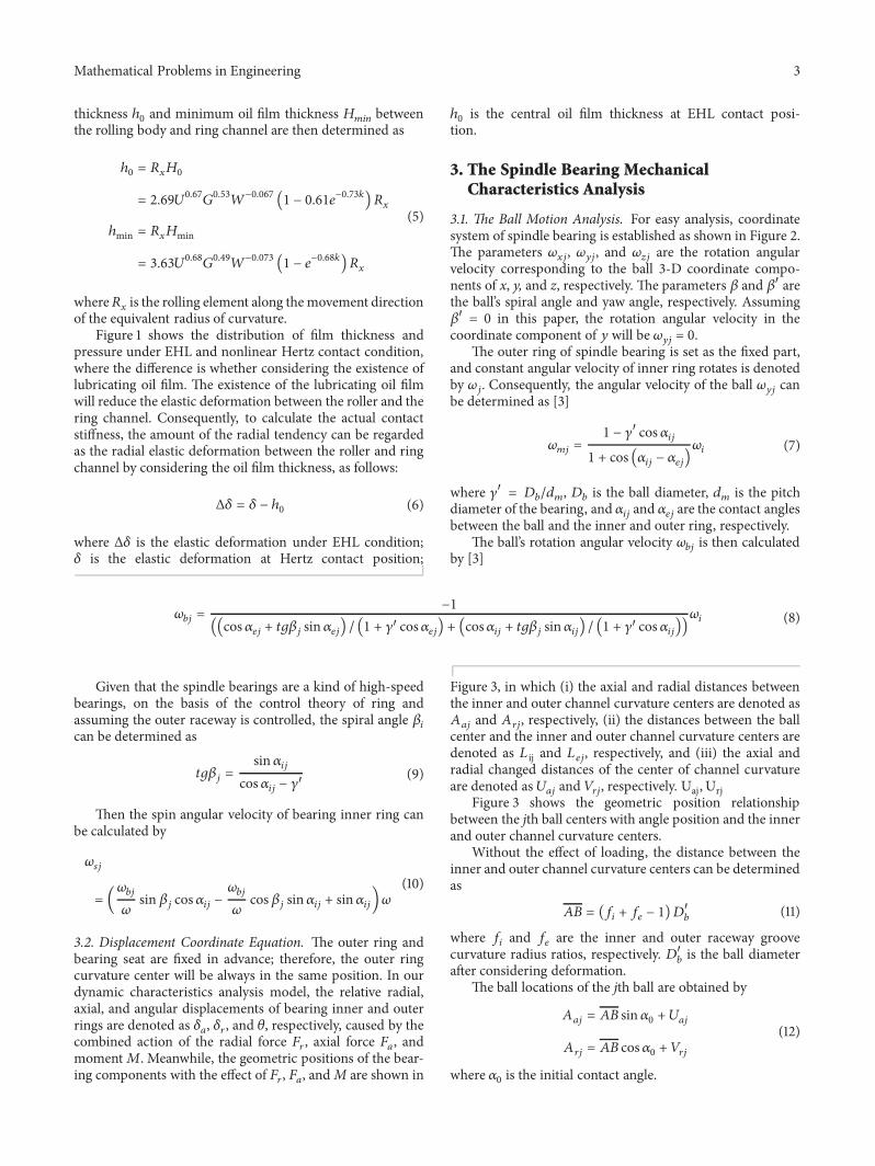
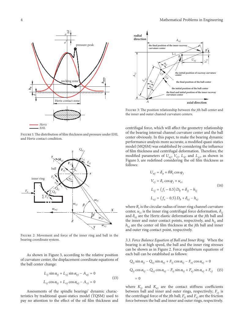
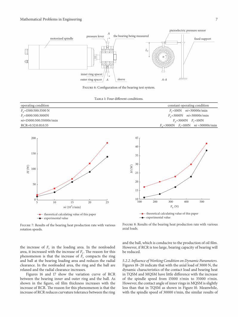
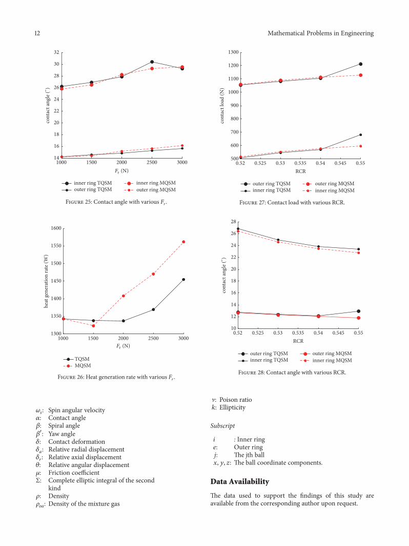
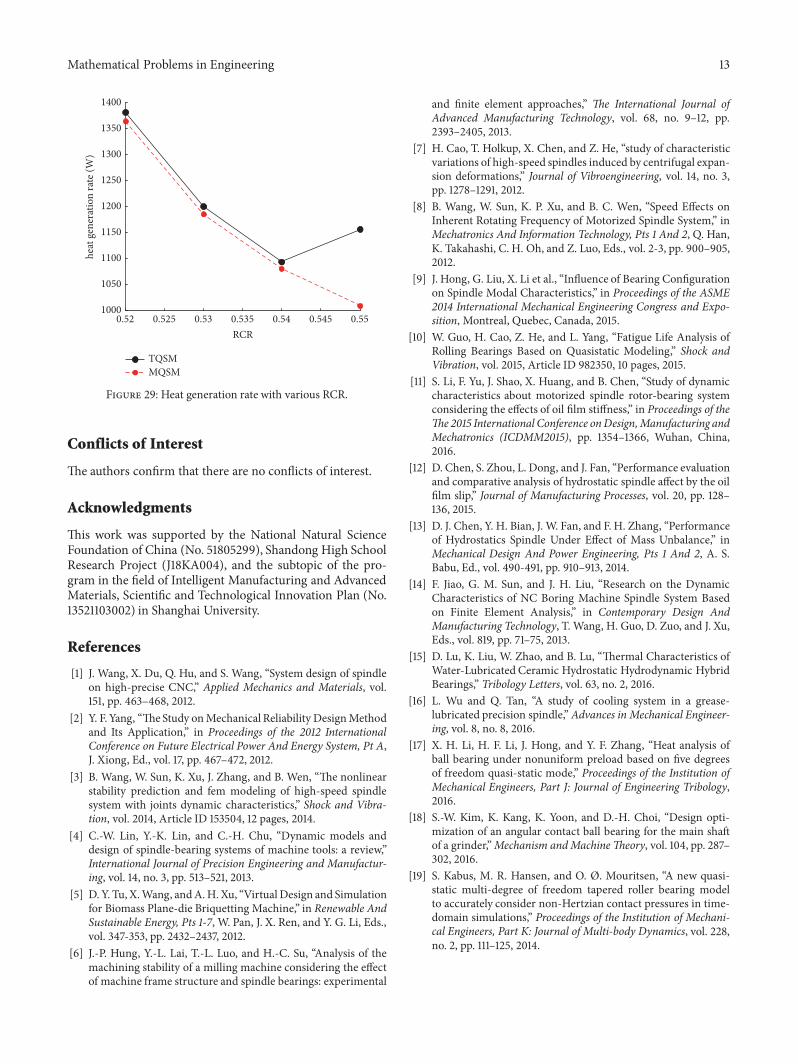

Hindawiwwwhindawicom Volume 2018
MathematicsJournal of
Hindawiwwwhindawicom Volume 2018
Mathematical Problems in Engineering
Applied MathematicsJournal of
Hindawiwwwhindawicom Volume 2018
Probability and StatisticsHindawiwwwhindawicom Volume 2018
Journal of
Hindawiwwwhindawicom Volume 2018
Mathematical PhysicsAdvances in
Complex AnalysisJournal of
Hindawiwwwhindawicom Volume 2018
OptimizationJournal of
Hindawiwwwhindawicom Volume 2018
Hindawiwwwhindawicom Volume 2018
Engineering Mathematics
International Journal of
Hindawiwwwhindawicom Volume 2018
Operations ResearchAdvances in
Journal of
Hindawiwwwhindawicom Volume 2018
Function SpacesAbstract and Applied AnalysisHindawiwwwhindawicom Volume 2018
International Journal of Mathematics and Mathematical Sciences
Hindawiwwwhindawicom Volume 2018
Hindawi Publishing Corporation httpwwwhindawicom Volume 2013Hindawiwwwhindawicom
The Scientific World Journal
Volume 2018
Hindawiwwwhindawicom Volume 2018Volume 2018
Numerical AnalysisNumerical AnalysisNumerical AnalysisNumerical AnalysisNumerical AnalysisNumerical AnalysisNumerical AnalysisNumerical AnalysisNumerical AnalysisNumerical AnalysisNumerical AnalysisNumerical AnalysisAdvances inAdvances in Discrete Dynamics in
Nature and SocietyHindawiwwwhindawicom Volume 2018
Hindawiwwwhindawicom
Dierential EquationsInternational Journal of
Volume 2018
Hindawiwwwhindawicom Volume 2018
Decision SciencesAdvances in
Hindawiwwwhindawicom Volume 2018
AnalysisInternational Journal of
Hindawiwwwhindawicom Volume 2018
Stochastic AnalysisInternational Journal of
Submit your manuscripts atwwwhindawicom