Assessment of Applicability of Standards Endorsed by ...
103
ORNL/SR-2017/520 notice: This document contains information of a preliminary Assessment of Applicability of Standards Endorsed by Regulatory Guides to Sodium Fast Reactors M. D. Muhlheim G. F. Flanagan W. P. Poore, III R. J. Belles September 2017
Transcript of Assessment of Applicability of Standards Endorsed by ...
ORNL/SR-2017/520
notice: This document contains information of a preliminary nature and is not intended for release It is subject to revision
Assessment of Applicability of Standards Endorsed by Regulatory Guides to Sodium Fast Reactors
M. D. Muhlheim G. F. Flanagan W. P. Poore, III R. J. Belles
September 2017
This report was prepared as an account of work sponsored by an agency of the United States Government. Neither the United States Government nor any agency thereof, nor any of their employees, makes any warranty, express or implied, or assumes any legal liability or responsibility for the accuracy, completeness, or usefulness of any information, apparatus, product, or process disclosed, or represents that its use would not infringe privately owned rights. Reference herein to any specific commercial product, process, or service by trade name, trademark, manufacturer, or otherwise, does not necessarily constitute or imply its endorsement, recommendation, or favoring by the United States Government or any agency thereof. The views and opinions of authors expressed herein do not necessarily state or reflect those of the United States Government or any agency thereof.

ORNL/SR-2017/520
Assessment of Applicability of Standards Endorsed by Regulatory Guides to Sodium Fast Reactors
M. D. Muhlheim G. F. Flanagan W. P. Poore, III
R. J. Belles
Date Published: September 2017
Prepared by OAK RIDGE NATIONAL LABORATORY
Oak Ridge, TN 37831-6283 managed by
UT-BATTELLE, LLC for the
US DEPARTMENT OF ENERGY under contract DE-AC05-00OR22725

v
CONTENTS
CONTENTS .................................................................................................................................................. v LIST OF FIGURES .................................................................................................................................... vii LIST OF TABLES ....................................................................................................................................... ix ACRONYMS ............................................................................................................................................... xi ACKNOWLEDGMENTS ......................................................................................................................... xiii EXECUTIVE SUMMARY ........................................................................................................................ xv ABSTRACT ............................................................................................................................................... xix 1. INTRODUCTION ................................................................................................................................ 1 2. SODIUM FAST REACTOR DESIGN DESCRIPTION ...................................................................... 5
2.1 Overall Reactor Description........................................................................................................ 5 2.1.1 Reactor Core and Fuel ................................................................................................... 8 2.1.2 Control and Protection System .................................................................................... 10 2.1.3 Electric Power Supplies ............................................................................................... 10 2.1.4 Residual Heat Removal System ................................................................................... 10 2.1.5 Reactor Containment ................................................................................................... 11 2.1.6 Primary Sodium Processing and Clean Up .................................................................. 13 2.1.7 Sodium Piping and Equipment Heating and Insulation System .................................. 13 2.1.8 Cover Gas Treatment ................................................................................................... 13
2.2 Major Differences between SFRs and LWRs ........................................................................... 13 3. SELECTION AND REVIEW OF STANDARDS.............................................................................. 15
3.1 Selection of Standards for Review ............................................................................................ 15 3.2 Review of Standards ................................................................................................................. 16 3.3 Level of Effort (LOE) ............................................................................................................... 17
3.3.1 No Changes (LOE 1) ................................................................................................... 17 3.3.2 Limited Changes (LOE 2) ............................................................................................ 18 3.3.3 Substantive Changes (LOE 3) ...................................................................................... 19 3.3.4 Unknown (LOE 4) ....................................................................................................... 21 3.3.5 N/A (LOE 5) ................................................................................................................ 21 3.3.6 New Standards Needed (LOE 6) .................................................................................. 22
4. RESULTS ........................................................................................................................................... 25 4.1 How Many ................................................................................................................................... 25 4.2 Amount of Effort Required ....................................................................................................... 26 4.3 twelve New Standards ............................................................................................................... 27 4.4 SDO and Industry Involvement ................................................................................................ 29 4.5 Distribution of Endorsed Standards in SRP .............................................................................. 31 4.6 I&C Standards Tend to Be Technology Neutral ....................................................................... 32 4.7 Applicability to Other SFR Designs ......................................................................................... 33 4.8 Summary of Results .................................................................................................................. 33
5. SDO APPROVAL AND NRC ENDORSEMENT OF CONSENSUS STANDARDS ...................... 35 5.1 SDO Approval .......................................................................................................................... 35 5.2 NRC Endorsement .................................................................................................................... 36
6. FUTURE WORK ................................................................................................................................ 39 7. REFERENCES ................................................................................................................................... 43 APPENDIX A. SFR Review of endorsed standards ................................................................................. A-1 APPENDIX B. IEEE Standards endorsed by Regulatory guides ............................................................. B-1

vi

vii
LIST OF FIGURES
Figure 1. PRISM primary system flow path. (Source: GEFR-00793, UC-87Ta). ........................................ 6
Figure 2. Intermediate heat exchanger. (Source: GEFR-00793, UC-87Ta).................................................. 7
Figure 3. Intermediate heat transport system and associated power conversion system. (Source: GEFR-00793, UC-87Ta).................................................................................................................. 8
Figure 4. Core layout. (Source: GEFR-00793, UC-87Ta). ........................................................................... 9
Figure 5. PRISM shutdown heat removal system. (Source: GEFR-00793, UC-87Ta). ............................. 11
Figure 6. Direct Reactor Auxiliary Cooling System (DRACS). (Source: GEFR-00793, UC-87Ta) .......... 11
Figure 7. S-PRISM vented containment. .................................................................................................... 12
Figure 8. Number of citations exceeds number of standards reviewed. ..................................................... 15
Figure 9. Number of standards endorsed by RGs by SDO/industry group. ................................................ 25
Figure 10. Level of effort to revise standards. ............................................................................................ 26
Figure 11. Level of effort for each SDO and industry group. ..................................................................... 30
Figure 12. SDOs and industry groups with substantive changes. ............................................................... 30
Figure 13. Number of standards and/or RGs cited in each SRP chapter. ................................................... 31

ix
LIST OF TABLES
Table 1. Plant performance characteristics (Source: GEFR-00793, UC-87Ta) ............................................ 6
Table 2. Fuel assembly data (Source: GEFR-00793, UC-87Ta) .................................................................. 9
Table 3. Guidance for performing review of standards .............................................................................. 16
Table 4. SFR review: examples of no changes to standard for applicability (LOE 1) ................................ 18
Table 5. SFR review: examples of limited review comments (LOE 2) ...................................................... 19
Table 6. SFR review: examples of substantive review comments (LOE 3) ............................................... 19
Table 7. SFR review: examples of reference information not applicable to the SFR design (LOE 4) .................................................................................................................................................... 21
Table 8. SFR review: examples of reference information not applicable to the SFR design (LOE 5) .................................................................................................................................................... 21
Table 9. SFR review: examples of proposed new standards applicable to the SFR design (LOE 6) ......... 22
Table 10. Number of standards endorsed by RGs by SDO/industry group ................................................ 25
Table 11. Level of effort to revise existing standards endorsed by RGs .................................................... 26
Table 12. Endorsed consensus standards and industry standards by an RG in Division 1 (Power Reactors) ........................................................................................................................................ 27
Table 13. SRP Table of Contents ................................................................................................................ 31
Table 14. RGs and endorsed standards not cited in the SRP. ..................................................................... 32
Table 15. Consensus standards references in the Code of Federal Regulations ......................................... 40


xi
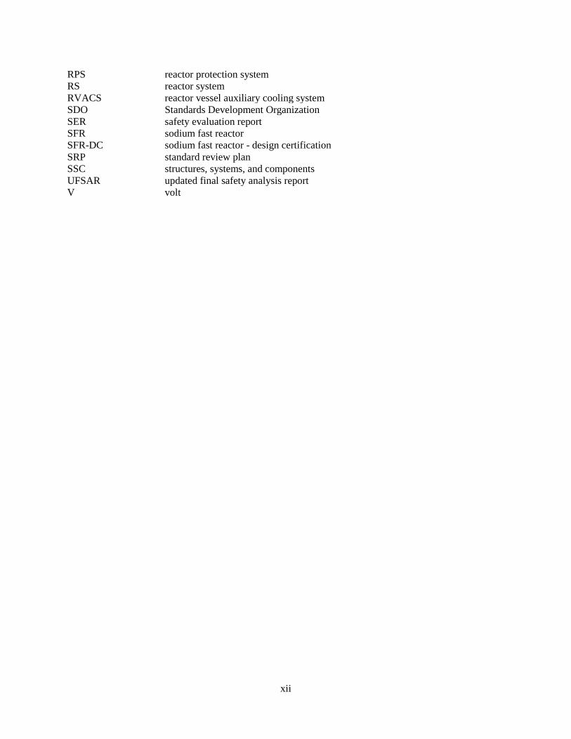
ACRONYMS
ac Alternating current ACI American Concrete Institute ACS auxiliary cooling system ANS American Nuclear Society ANSI American National Standards Institute ASME American Society of Mechanical Engineers ASTM American Society for Testing and Materials BSR Board of Standards Review BTP branch technical position °C degrees centigrade CFR Code of Federal Regulations dc Direct current DOE US Department of Energy DRACS direct reactor auxiliary cooling system EM electromagnetic EPRI Electric Power Research Institute GDC general design criteria GE General Electric HAA head access area IAEA International Atomic Energy Agency IAP implementation action plan ID identification number IEEE Institute of Electrical and Electronic Engineers IHTS intermediate heat transport system IHX intermediate heat exchanger IMC inspection manual chapter IP inspection procedure ISA Instrumentation Society of America ISG interim staff guidance LWR light-water reactor mHTGR modular high-temperature gas reactor MSR molten salt reactor MWt megawatt thermal N/A not applicable NEI Nuclear Energy Institute NFPA National Fire Protection Association NRC US Nuclear Regulatory Commission OMB Office of Management and Budget PCS plant control system PRISM Power Reactor Inherently Safe Module PSID preliminary system information document PSPS primary sodium processing subsystem PWR pressurized water reactor RCPB reactor coolant pressure boundary RG regulatory guide RHR residual heat removal
xii
RPS reactor protection system RS reactor system RVACS reactor vessel auxiliary cooling system SDO Standards Development Organization SER safety evaluation report SFR sodium fast reactor SFR-DC sodium fast reactor - design certification SRP standard review plan SSC structures, systems, and components UFSAR updated final safety analysis report V volt

xiii
ACKNOWLEDGMENTS
This project was funded by the US Department of Energy’s Office of Nuclear Energy under the Advanced Reactor Regulatory Framework Program.


xv
EXECUTIVE SUMMARY
The benefits of the use of voluntary consensus standards and industry standards is evident in the design and licensing of the current generation of nuclear power plants The use of voluntary consensus standards and industry standards would be helpful in the design and licensing of advanced reactors to improve the effectiveness and efficiency of the licensing and regulation of non-LWR technologies. Most of the regulations, guidance, and standards applicable to nuclear power plants were developed for water-cooled plants, so they may not adequately address the coolants, materials, temperatures, operations, testing, maintenance, etc., proposed for advanced reactors.
Consistent with Office of Management and Budget (OMB) Circular A119, it is the policy of the Nuclear Regulatory Commission (NRC) to use standards developed by voluntary consensus standards bodies if available and appropriate. The NRC incorporates by reference consensus standards to provide the certainty and predictability desired by stakeholders. This approach also minimizes the expenditure of NRC resources that would otherwise be necessary to develop new regulations at a level of detail comparable to that provided by existing consensus standards. Part of the NRC’s near-term strategies to review and regulate a new generation of non-light-water reactors (non-LWRs) includes:1
• Working with stakeholders to determine the currently available codes and standards applicable to non-LWRs and to identify the technical areas where gaps exist
• Participating with the standards development organizations (SDOs) that are actively involved in developing codes and standards for non-LWRs
• Reviewing codes and standards for endorsement
The NRC’s mid/long-term action plan recognizes that it typically takes years to develop consensus codes and standards or to promulgate a new or revised regulation.
The NRC’s regulatory framework is specific to LWRs. Similarly, the guidance for meeting regulatory requirements is primarily applicable to water-cooled nuclear power plants. Not surprisingly, many industry consensus standards cited or referenced in regulatory documents such as the NRC Standard Review Plan (LWR edition) (NUREG-0800), regulatory guides (RGs), the Code of Federal Regulations (CFR), NRC bulletins, information notices, circulars, generic letters, and policy statements are specific to LWRs.
To understand the size and scope of work required to expand the regulatory framework to address non-LWRs, a pilot program was initiated to provide the US Department of Energy (DOE) with the following:
1. an estimate of the number of standards that need revision, 2. an estimate of the levels of effort required to revise those standards, 3. a description of the process for revising or creating a new standard, and 4. a description of the NRC’s process for endorsing a standard.
1 NRC Vision and Strategy: Safely Achieving Effective and Efficient Non-Light Water Reactor Mission Readiness, December 2016. (ML16356A670)
xvi
In the pilot, program, the scope was limited to focus on sodium fast reactors (SFRs). This pilot project focused on RGs because they are frequently used to endorse standards that provide an acceptable method for satisfying NRC regulations.
Because this is a pilot program, this review focused on the applicability of standards to an SFR. Of those standards selected for the focused review, their relative applicability to less developed technologies was evaluated at a high level. It is outside the scope of this review to prioritize the NRC or SDO standard development activities or to relate their development to the NRC mission.
The first step in estimating the size and scope of the effort to ensure that the standards support the industry’s activities for advanced reactors was to obtain a list of all standards cited in RGs. This step identified 865 standards cited in RGs.
The second step was to narrow down the number of standards for an in-depth review to assess their potential application for SFRs. The objective of the down-selection process was to limit the review to standards endorsed, partially endorsed, or endorsed with exceptions by RGs in Div. 1 (Power Reactors) that are active (i.e., the RG has not been withdrawn). This step identified 114 standards; however; the 43 standards from the Institute of Electrical and Electronics Engineers (IEEE) were reviewed separately because they were expected to be technology neutral (this assumption was confirmed by a separate review). Of the remaining 71 standards, 11 were duplicates, leaving 60 standards for detailed review.
The third step was to review the 60 standards for their applicability to SFRs and to identify the need for new standards unique to SFRs. This step identified 12 potential new standards.
Of the 60 reviewed standards endorsed by RGs, 46 were voluntary consensus standards, and 14 were from industry. About 40% will not require any changes—18 standards with no changes and 5 standards that are not applicable. Of the other ~60% of standards reviewed, 16 will require minor changes, 19 will require significant changes, and there was insufficient information available to assess the applicability of 2 standards. Significant changes are because of the higher energy spectrum, higher temperatures, and corrosive coolants. Material properties for metals, concrete, and protective coatings will need to be addressed.
The 12 new standards needed are likely to be developed by an SDO such as ANS (7) or ASME (5). These new standards are the result of the increased use of passive systems and sodium environment.
This review then evaluated the basic development process for a new standard or the process of revising an existing standard. The amount of time required to develop or modify a standard is related to the complexity of changes needed, up to and including the development of a new standard. The development and approval of a new standard by an SDO is likely to be in the 5–8 year range.
For an approved standard to be used in the regulatory process, it must be endorsed by NRC in regulations (i.e., codified) or as guidance (e.g., in a RG, NUREG, or the SRP). The review and NRC endorsement of codes and standards (with possible clarifications and exceptions) can only follow the development and issuance of a standard by the SDOs. This endorsement process could add years to the adaptation of a standard in the regulatory process, with additional time needed if the approval is made through a regulation compared to guidance.
With respect to licensing an SFR, the 12 new standards should be the priority, with standards requiring significant changes being a close second. Delays in addressing these changes will directly affect the licensing timeline and commercial deployment. In addition, a staggered submittal of requests will be necessary to prevent overwhelming an SDO.
xvii
This pilot project reviewed only those standards endorsed by RGs. However, not all of the standards that provide an acceptable method for meeting NRC regulations are endorsed in RGs. For example, the acceptance criteria in the SRP occasionally cite standards that provide an approved method but that are not endorsed by an RG. The number of standards approved by the SRP but not selected through the RG process was not quantified in this pilot program. This limitation in the pilot project will have an effect on licensing of non-LWRs due to the gap that exists in the use of standards to support licensing an SFR.
Future efforts should focus on
• Determining the number of standards and level of effort needed for applicability to SFRs by identifying and assessing standards approved in the SRP (similar to endorsed standards in RGs)
• Assessing the standards enforced by regulations (i.e., requirements via the code of federal regulations)
• Preparing draft revisions to the standards to reflect their applicability to SFRs, highlighting where data are insufficient
• Describing the process of creating a new standard to document the process of selecting a topic, requesting a new standard from an SDO, interacting with NRC, and developing the standard.
• Ranking the 31 standards according to those requiring significant changes (19) or those that are new (12) based on applicability to other reactor types, whether data exist or research is needed to collect data, and their impact on an SDO. (Note that the volume of requests must be gauged, and a process to stagger submittal of requests will be needed to prevent overwhelming an SDO).
• This review focuses on SFRs and should be expanded to other reactor technologies (MSRs, gas, etc.)
The use of codes and standards will be integral to the NRC’s strategy to improve readiness to regulate non-LWR technologies. If a consensus standard is not available then NRC can create its own guidance, and if a standard is available then NRC must justify why it is not being used. There is a great advantage to industry to create the standards themselves rather than to have a standard or guidance imposed on them.
Designs can proceed without approved standards, but approved standards can help with multiple licensees. Advanced reactor technology licensing and deployment will likely be delayed significantly if applicable and endorsed standards are not available for use by both technology developers and the NRC. Delays in providing the NRC with the knowledge base and tools for reviewing non-LWR applications will increase the effort needed to review an application and in turn will delay its approval.

xix
ABSTRACT
The benefits of the use of voluntary consensus standards and industry standards is evident in the design and licensing of the current generation of nuclear power plants The use of voluntary consensus standards and industry standards would be helpful in the design and licensing of advanced reactors to improve the effectiveness and efficiency of the licensing and regulation of non-LWR technologies. However, most of the regulations, guidance, and standards applicable to nuclear power plants were developed for water-cooled plants and may not adequately address the coolants, materials, temperatures, operations, testing, maintenance, etc., proposed for advanced reactors.
Consistent with OMB Circular A119, it is the policy of the Nuclear Regulatory Commission (NRC) to use standards developed by voluntary consensus standards bodies if available and appropriate. The NRC’s mid/long-term action plan recognizes that it has typically taken years to develop consensus codes and standards and promulgate a new or revised regulation.
The NRC’s regulatory framework is specific to LWRs. Similarly, the guidance for meeting its regulatory requirements is primarily applicable to water-cooled nuclear power plants. Not surprisingly, many of industry consensus standards cited or referenced in regulatory documents such as the NRC Standard Review Plan (LWR edition) (NUREG-0800), regulatory guides (RGs), the Code of Federal Regulations (CFR), NRC bulletins, information notices, circulars, generic letters, and policy statements are also specific to LWRs.
To understand the size and scope of work required to expand the regulatory framework to address non-LWRs, a pilot program was initiated to provide DOE with the following:
1. an estimate of the number of standards that need revision, 2. an estimate of the levels of effort required to revise those standards, and 3. a description of the process for revising or creating a new standard, and 4. a description of the NRC’s process for endorsing a standard.
The first step was to obtain a list of all standards cited in RGs which are frequently used to endorse standards for providing an acceptable method for satisfying NRC’s regulations. This step identified 865 standards.
The second step was to narrow down the number of standards for an in-depth review to assess their potential application for an SFR. The objective of the down-selection process was to limit the review to standards endorsed, partially endorsed, or endorsed with exceptions by RGs in Div. 1 (power reactors) that are active (i.e., the RG has not been withdrawn). This step identified 114 standards, but the 43 IEEE standards were reviewed separately because they were expected to be technology neutral, and this was confirmed by a separate review. Of the remaining 71 standards, 11 were duplicates, leaving 60 standards for detailed review.
The third step was to review the 60 standards for their applicability to SFRs and to identify the need for new standards unique to SFRs. This step identified 12 potential new standards.
This review then evaluated the basic development process for a new standard or the process of revising an existing standard. The amount of time to develop or modify a standard is related to the complexity of changes needed, up to and including the development of a new standard. The development and approval of a new standard by an SDO is likely to be in the 5–8 year range.
xx
For an approved standard to be used in the regulatory process, it must be endorsed by NRC in regulations (i.e., codified) or as guidance (e.g., in a RG, NUREG, or the SRP). The review and NRC endorsement of codes and standards (with possible clarifications and exceptions) can only follow the development and issuance of a standard by the SDOs. This endorsement process could add years to the adaptation of a standard in the regulatory process, with additional time needed if the approval is made through a regulation compared to guidance.
1
1. INTRODUCTION
The benefits of the use of voluntary consensus standards and industry standards is evident in the design and licensing of the current generation of nuclear power plants The use of voluntary consensus standards and industry standards would be helpful in the licensing of advanced reactors to improve the effectiveness and efficiency of the licensing and regulation of non-LWR technologies. However, most of the regulations, guidance, and standards applicable to nuclear power plants were developed for water-cooled plants and may not adequately address the coolants, materials, temperatures, operations, testing, maintenance, etc., proposed for advanced reactors.
Consistent with OMB Circular A119 [1], it is Nuclear Regulatory Commission’s (NRC’s) policy to use standards developed by voluntary consensus standards bodies if available and appropriate [2, 3]. The NRC incorporates by reference consensus standards to provide the regulatory certainty and predictability desired by stakeholders, minimizing the expenditure of NRC resources that would otherwise be necessary to develop regulations with a level of detail comparable to that provided by consensus standards [4]. Part of the NRC’s near-term strategies to review and regulate a new generation of non-light-water reactors (non-LWRs) includes [5]:
• Working with stakeholders to determine the currently available codes and standards applicable to non-LWRs and to identify the technical areas where gaps exist
• Participating with the standards development organizations (SDOs) that are actively involved in developing codes and standards for non-LWRs
• Reviewing codes and standards for endorsement
The NRC’s mid/long-term action plan recognizes that it has typically taken years to develop consensus codes and standards and promulgate a new or revised regulation [6]. The number of standards involved and the level of effort needed to revise or develop new standards applicable to non-LWRs are still to be determined.
The NRC’s regulatory framework is specific to LWRs, so the guidance for meeting these regulatory requirements was developed for water-cooled nuclear power plants. Not surprisingly, many industry consensus standards cited or referenced in regulatory documents such as the NRC Standard Review Plan (LWR edition) (NUREG-0800), regulatory guides (RGs), the Code of Federal Regulations (CFR), NRC bulletins, information notices, circulars, generic letters, and policy statements are also LWR-specific.
It is not known how many existing standards would apply in licensing a non-LWR, what changes would be needed so that the scope of the standard addresses issues related to non-LWRs, and if new standards would be required to address new technological issues introduced by non-LWR technology. The time required to revise, develop, approve, and endorse a new or revised standard for applicability to an advanced reactor must also be estimated.
To understand the size and scope of work required to expand the regulatory framework to address non-LWRs, a pilot program was initiated to provide DOE with
2. an estimate of the number of standards that need revision, 3. an estimate of the level of effort required to revise those standards, 4. a description of the process for revising or creating a new standard, and
2
5. a description of the NRC’s process for endorsing a standard.
In the pilot program, the scope was limited to sodium fast reactors (SFRs) and focused on RGs because they are one of several guidance documents that describe an acceptable method for applicants and licensees to meet specific provisions of the NRC’s regulations, techniques used by the staff members to evaluate specific problems or postulated accidents, or data needed by staff members to review applications for permits and licenses.
The first step was to obtain a list of all standards cited in RGs, including consensus standards and industry standards. From this list, a down-selecting process was used to select a few standards for in-depth review to assess their potential application for SFR technologies. This process was based on standards being endorsed by an RG and that the RG was active (i.e., not withdrawn). This served two purposes:
1. To narrow down the number of standards for review to endorsed standards to discern how many would require review
2. Categorize the level of effort1 required to develop or revise each standard for applicability to an SFR to determine the level of effort needed.
For an approved standard to be used in the regulatory process, it must be endorsed by NRC in regulations (i.e., codified) or as guidance (e.g., in an RG, NUREG, or the SRP). The review and NRC endorsement of codes and standards (with possible clarifications and exceptions) can only follow the development and issuance of a standard by the SDOs. This endorsement process could add years to the adaptation of a standard in the regulatory process, with additional time needed if the approval is made through a regulation compared to guidance.
This pilot project is the first step in estimating the size and scope of standards to be revised or created to aid in licensing an SFR. The next task is to provide detailed assessments and inputs in support of (1) revision of existing consensus standards, (2) development of new standards to be used to justify the need for a new or revised standard to the SDO. Assessments and inputs will also help to prioritize the 31 standards for revision or development (19 with significant changes and 12 new). The ranking would be based on applicability to other reactor types, whether data exist or research is needed to collect data, and the data’s impact on an SDO. Efforts will be made to gauge the volume of requests and stagger the submittal of requests to prevent overwhelming an SDO. This review was focused on SFRs and should be expanded to other reactor technologies (e.g., molten salt reactors [MSRs], gas, etc.). Engagement with NRC and the SDOs is essential during these efforts.
This review then evaluated the basic development process for a new standard or the process to revise an existing standard. A range of time periods for development or modification of a standard is related to the complexity of changes needed up to and including the development of a new standard. Development and approval of a new standard by an SDO is likely to take ~5 years.
This pilot project reviewed only those standards endorsed by RGs. However, not all of the standards that provide acceptable methods for meeting NRC regulations are endorsed in RGs. For example, the
1 “Level of effort” represents the amount of changes that might be required and not the amount of resources and time to make those changes.

3
acceptance criteria in the Standard Review Plan (SRP) occasionally cite standards that provide an approved method but are not endorsed by an RG. In addition, the number of standards approved (endorsed) by the SRP but not selected through the RG process was not quantified in this pilot program.
Section 2 of this report provides a short description of an SFR.
Section 3 describes the structured process that guided the review of the standards.
Section 4 presents an overview of the results of the review.
Section 5 describes the process for creating or revising a consensus standard and the NRC endorsement process for a standard.
Section 6 recommends the next steps to revise or create a new standard.
Appendix A presents the detailed review results for the 60 consensus and industry standards endorsed by RGs and the 12 recommended standards.

5
2. SODIUM FAST REACTOR DESIGN DESCRIPTION
2.1 OVERALL REACTOR DESCRIPTION
The PRISM power plant is described to illustrate design features typical of pool-type SFR reactors. It consists of nine reactor modules, each of which produces 425 MWt. The design emphasizes inherent safety characteristics and modularity. The small size of the modules allows the use of inherent shutdown and passive decay heat removal features that permit simplification of safety-related systems in the plant. This advanced reactor design is consistent with the NRC advanced reactor policy statement [7] regarding such features.
The reactor uses metal fuel and employs a pool-type design configuration for each module. All primary system components are located inside the reactor vessel. Each reactor module is below grade.
The active core height is 47 inches, with a linear heat rate of <12 kWt/ft. The core outlet temperature is 468°C. The reactivity and power are controlled by six control assemblies which also scram the reactor using two diverse actuators when rapid shutdown is required.
The primary heat transport system is contained within the reactor vessel. It is composed of the hot pool, the shell side of the intermediate heat exchanger (IHX), the cold pool, four submersible electromagnetic (EM) pumps, the pump discharge piping, and the core inlet plenum. The sodium exits the IHX at its base and enters the cold pool.
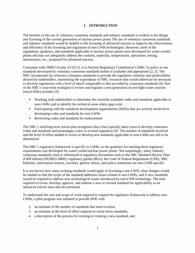
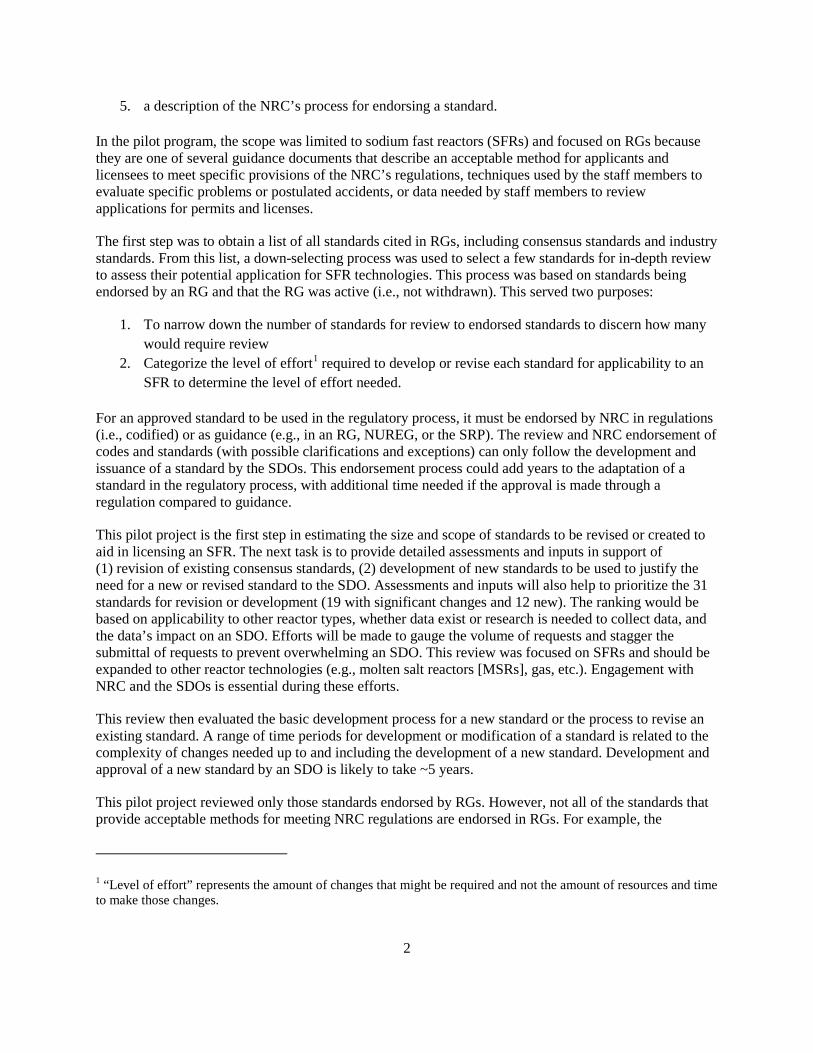
From the pump suction, cold pool sodium is drawn through the fixed shield assemblies to the pump inlet manifold. The four EM pumps draw in cold pool sodium and discharge it into the high-pressure core inlet plenum through piping connecting each pump to the plenum. The sodium is then heated as it flows upward through the core and into the hot pool. The primary system flow path is shown in Figure 1.
Two IHXs are located in the reactor vessel. These are connected to one intermediate heat transport loop containing sodium as the heat transport fluid. The heat is transported via a steam generator to a turbine, which is shared by two other reactor modules to make up a power block. The PRISM plant design consists of three power blocks, each of which consists three reactor modules connected to one turbine. A summary of the PRISM plant performance characteristics is found in Table 1 [8].
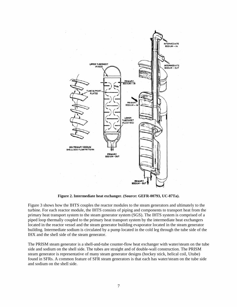
The IHX (Figure 2) consists of upper and lower tube sheets separated by straight tubes with a central downcomer for incoming intermediate sodium, and riser for outgoing intermediate sodium. Primary sodium from the hot pool enters the IHX at an elevation below the upper tube sheet. The primary sodium flows downward around the tube and shell to above the lower tube sheet, and then it exits into the reactor cold plenum. The cold leg intermediate sodium flows down the central downcomer and splits into two streams just below the lower tube sheet. Each stream then flows up through the straight tubes. The intermediate sodium exits the bundle just above the upper tube sheet. This sodium leaves the IHX through the intermediate outlet nozzle for use in the intermediate heat transport system (IHTS).
6
Figure 1. PRISM primary system flow path. (Source: GEFR-00793, UC-87Ta).
Table 1. Plant performance characteristics (Source: GEFR-00793, UC-87Ta)
Overall plant Number of reactor modules Nine Plant thermal power 3,825 MWt Net electrical output 1,245 MWe Net station efficiency 32.4% Turbine throttle conditions 965 psia / 540°F
Reactor module Thermal power (core 425 MWt Primary sodium inlet/outlet temperature 610°F / 875°F Primary sodium flow rate 40,800 GPM Intermediate sodium inlet/outlet temperature 540°F / 800°F Intermediate sodium flow rate 41,000 GPM
Feedwater temperature 420°F IHTS hot leg temperature 800°F IHTS cold leg temperature 540°F Steam cycle Saturated Turbine type 1,800 RPM, tandem compound, four flow −38-inch last stage
bucket
7
Figure 2. Intermediate heat exchanger. (Source: GEFR-00793, UC-87Ta).
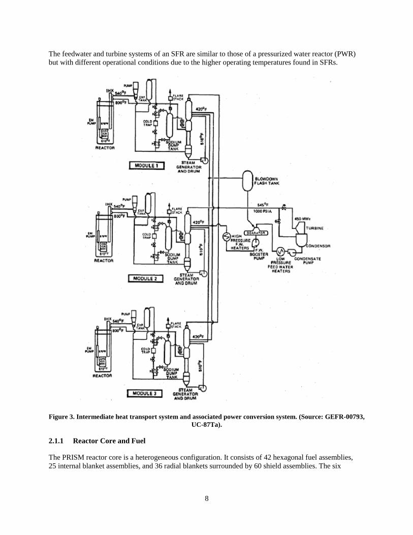
Figure 3 shows how the IHTS couples the reactor modules to the steam generators and ultimately to the turbine. For each reactor module, the IHTS consists of piping and components to transport heat from the primary heat transport system to the steam generator system (SGS). The IHTS system is comprised of a piped loop thermally coupled to the primary heat transport system by the intermediate heat exchangers located in the reactor vessel and the steam generator building evaporator located in the steam generator building. Intermediate sodium is circulated by a pump located in the cold leg through the tube side of the IHX and the shell side of the steam generator.
The PRISM steam generator is a shell-and-tube counter-flow heat exchanger with water/steam on the tube side and sodium on the shell side. The tubes are straight and of double-wall construction. The PRISM steam generator is representative of many steam generator designs (hockey stick, helical coil, Utube) found in SFRs. A common feature of SFR steam generators is that each has water/steam on the tube side and sodium on the shell side.
8
The feedwater and turbine systems of an SFR are similar to those of a pressurized water reactor (PWR) but with different operational conditions due to the higher operating temperatures found in SFRs.
Figure 3. Intermediate heat transport system and associated power conversion system. (Source: GEFR-00793, UC-87Ta).
2.1.1 Reactor Core and Fuel
The PRISM reactor core is a heterogeneous configuration. It consists of 42 hexagonal fuel assemblies, 25 internal blanket assemblies, and 36 radial blankets surrounded by 60 shield assemblies. The six

9
control/shutdown assemblies are located in the core. A core layout is shown in Figure 4. Fuel assembly information is contained in Table 2 [8].
Figure 4. Core layout. (Source: GEFR-00793, UC-87Ta).
Table 2. Fuel assembly data (Source: GEFR-00793, UC-87Ta)
Reference core fuel assembly data Duct pitch 6.282 in. Duct material HT9 Duct gap 0.175 in. Duct wall thickness 0.140 in. Duct outer flat to flat 6.107 in. Duct inner flat to flat 5.827 in. Overall assembly length 186. in. Bundle flow area 10.88 in. Pins per assembly 271 Pin spacer Straight start wire wrap Pin pitch/diameter 1.199 Fuel height 47 in. Upper gas plenum height 70 in. Upper shielding Upper gas plenum Lower shielding 40 in.
Pin data Fuel type U-Pu-10%Zr Pin overall length 158 in. Pin outer diameter 0.290 in. Cladding material HT9 Cladding thickness 0.022 in. Fuel diameter 0.213 in.
10
2.1.2 Control and Protection System
Each reactor module has two diverse scram methods; a gravity-driven rod drop and a powered rod drive-in. Shutdown redundancy is provided by designing each absorber bundle using natural boron as the absorber. so This ensures that there is sufficient worth to shut down the reactor from hot full power condition to cold zero power condition, with the remaining five rods withdrawn to the normal full power operating position. The digital reactor protection system (RPS) is entirely independent from the plant control system (PCS). The automated operation of nine reactor modules and three turbine-generators (three power blocks) is supervised from a centralized plant control room.
2.1.3 Electric Power Supplies
For each unit, the electric power system consists of a non-class 1E A-C power system and a Class 1E dc power system. The non-Class 1E high voltage A-C system interfaces with four divisions of the 125 V dc system via the rectifier/charger units. This also provides protection against A-C transients from the station auxiliary ac system reflecting into the Class 1E system. The four divisions of Class 1E 125 V dc power are all battery backed. The four divisions of dc power also supply static inverters, which provide four isolated Class 1E 120 V vital ac busses.
2.1.4 Residual Heat Removal System
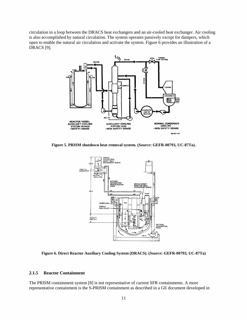
The residual heat removal (RHR) system for the PRISM design [8] consists of the normal heat removal pathway that transfers heat generated in the reactor core to the steam generator system, where it is transported via the feedwater and steam system through turbine bypass valves to the turbine condenser. To remove reactor shutdown heat when the normal heat removal pathway is not available, a safety-grade reactor shutdown heat removal system—the Reactor Vessel Auxiliary Cooling System (RVACS)—is provided in the PRISM. In addition to the RVACS, a safety-grade Auxiliary Cooling System (ACS) is provided in the S-PRISM design (the ACS is a non-safety-grade system in the PRISM design). Figure 5 shows the PRISM shutdown heat removal system, including the RVACS, ACS, and the normal condenser cooling system.
The RVACS operates by passively transferring heat generated in the core to the sodium coolant, which increases the temperature of the reactor vessel wall. The heat from the reactor vessel wall is radiated to the containment vessel wall across the argon gas–filled gap between the reactor vessel and the containment vessel. As the reactor vessel wall temperature increases, radiant heat transfer between the reactor vessel wall and the containment wall increases rapidly. The containment vessel wall is cooled by the circulation of outside air. This passive system is always in operation.
The ACS in both the PRISM and the S-PRISM design is a passive system that operates when the normal heat removal pathway via the steam generator feedwater system and turbine bypass system to the turbine condenser are not available. System operation does not require either the primary system pumps or the IHTS system pumps to operate. Primary system heat is transferred passively to the IHTS through the intermediate heat exchanger by natural convection. The IHTS circulates passively through the shell side of the steam generator. The steam generator is surrounded by an insulated shroud with an air intake at the bottom and an exhaust isolation damper at the top. Outside air circulates around the steam generator shell to remove decay heat. The ACS initiates when the exhaust damper is opened. Although not used in the PRISM or S-PRISM designs, some SFR designs employ a passive RHR system known as a direct reactor auxiliary cooling system (DRACS). In a DRACS, decay heat removal heat exchangers are immersed directly into the primary coolant system. Sodium or a sodium-compatible fluid flows by natural
11
circulation in a loop between the DRACS heat exchangers and an air-cooled heat exchanger. Air cooling is also accomplished by natural circulation. The system operates passively except for dampers, which open to enable the natural air circulation and activate the system. Figure 6 provides an illustration of a DRACS [9].
Figure 5. PRISM shutdown heat removal system. (Source: GEFR-00793, UC-87Ta).
Figure 6. Direct Reactor Auxiliary Cooling System (DRACS). (Source: GEFR-00793, UC-87Ta)
2.1.5 Reactor Containment
The PRISM containment system [8] is not representative of current SFR containments. A more representative containment is the S-PRISM containment as described in a GE document developed in
12
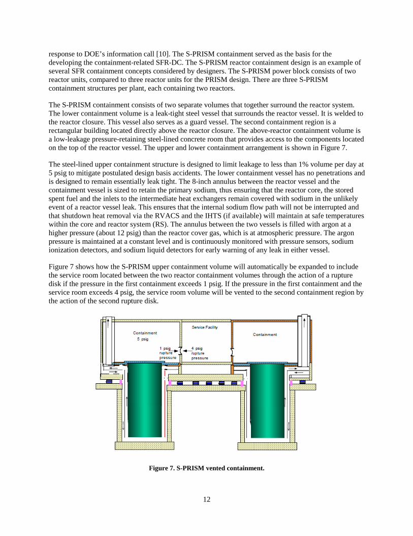
response to DOE’s information call [10]. The S-PRISM containment served as the basis for the developing the containment-related SFR-DC. The S-PRISM reactor containment design is an example of several SFR containment concepts considered by designers. The S-PRISM power block consists of two reactor units, compared to three reactor units for the PRISM design. There are three S-PRISM containment structures per plant, each containing two reactors.
The S-PRISM containment consists of two separate volumes that together surround the reactor system. The lower containment volume is a leak-tight steel vessel that surrounds the reactor vessel. It is welded to the reactor closure. This vessel also serves as a guard vessel. The second containment region is a rectangular building located directly above the reactor closure. The above-reactor containment volume is a low-leakage pressure-retaining steel-lined concrete room that provides access to the components located on the top of the reactor vessel. The upper and lower containment arrangement is shown in Figure 7.
The steel-lined upper containment structure is designed to limit leakage to less than 1% volume per day at 5 psig to mitigate postulated design basis accidents. The lower containment vessel has no penetrations and is designed to remain essentially leak tight. The 8-inch annulus between the reactor vessel and the containment vessel is sized to retain the primary sodium, thus ensuring that the reactor core, the stored spent fuel and the inlets to the intermediate heat exchangers remain covered with sodium in the unlikely event of a reactor vessel leak. This ensures that the internal sodium flow path will not be interrupted and that shutdown heat removal via the RVACS and the IHTS (if available) will maintain at safe temperatures within the core and reactor system (RS). The annulus between the two vessels is filled with argon at a higher pressure (about 12 psig) than the reactor cover gas, which is at atmospheric pressure. The argon pressure is maintained at a constant level and is continuously monitored with pressure sensors, sodium ionization detectors, and sodium liquid detectors for early warning of any leak in either vessel.
Figure 7 shows how the S-PRISM upper containment volume will automatically be expanded to include the service room located between the two reactor containment volumes through the action of a rupture disk if the pressure in the first containment exceeds 1 psig. If the pressure in the first containment and the service room exceeds 4 psig, the service room volume will be vented to the second containment region by the action of the second rupture disk.
Figure 7. S-PRISM vented containment.

13
2.1.6 Primary Sodium Processing and Clean Up
The primary sodium processing subsystem (PSPS) [8] provides purification of sodium contained in the reactor vessel. It also provides the capability to transfer and temporarily store primary sodium during periods of reactor assembly replacement. There is one system for each power block. Connecting lines are isolated so that only one reactor module can be processed at a time. Primary sodium processing occurs during reactor refueling periods. Prior to plant start-up, the primary sodium processing system is used to purify the fresh sodium and to clean the internals of the reactor vessel. Sodium is pumped through a nitrogen-cooled cold trap to purify the sodium. Double isolation valves are located inside the reactor head access area (HAA) and next to the processing equipment to limit the consequences of postulated sodium spills.
2.1.7 Sodium Piping and Equipment Heating and Insulation System
The function of the sodium piping and equipment heating and insulation system is to liquefy and maintain the sodium as a liquid. The system comprises electrical trace heating and reactor vessel preheating equipment, as well as pipe and vessel insulation. Thermocouple monitors and solid-state delays control the power to the cables and thus control the heat rate. There are local and global control centers for the heating system. The reactor vessel preheating system consists of two self-contained blower heater packages. The insulation for the systems consists of alumina silica sandwiched between layers of stainless steel.
2.1.8 Cover Gas Treatment
The PRISM reactor is designed to operate as a hermetically sealed system that is opened only for refueling or maintenance, so there is no feed/bleed of reactor cover gas during operation. Before refueling, the helium cover gas is replaced with clean gas. A portable, vehicle-mounted, helium gas supply system [8] is provided to evacuate, purge, and establish the reactor cover gas pressure at refueling. The system consists of a helium supply, filter, vacuum pump, receiver tank, vapor trap, compressor, and storage/transfer tank. The reactor cover gas is evacuated from the reactor before refueling to the receiver tank through the vapor trap using the vacuum pump. From the receiver tank, the cover gas is transferred to the helium storage/transfer tank using the compressor. The cover gas is replenished with clean helium. The radioactive reactor cover gas is collected by the mobile unit and is then transferred to the gaseous radioactive-waste system for processing. The waste is kept in storage for 45 days for the radioactivity to decay to allowable levels, and then it is reused or discharged to the atmosphere through a monitored exhaust.
2.2 Major Differences between SFRs and LWRs
SFR designs are distinguished from traditional LWR designs in a number of important aspects:
1. The fast neutron spectrum (minimum use of moderating materials in the core) results in a more compact core design
2. The sodium coolant has a high thermal heat conductivity, allowing better heat removal from the fuel and resulting in a higher core power density
3. The sodium coolant has a high boiling point (880°C), allowing the SFR to operate at near-atmospheric pressure with about a 300°C margin above the peak coolant operating temperatures of 550°C
4. Sodium has a melting point of about 98°C, resulting in the need for freeze prevention for the reactor and piping systems
14
5. Exposure of sodium to neutrons in the core forms sodium-24, a short-lived (15-hour half-life) beta/gamma emitter which requires a leak-tight primary system and sodium leak detection capability
6. Sodium is chemically reactive with air, water, and concrete, which must be taken into account in reactor design and operation
Because of the chemical reaction with sodium and water, an SFR employs an intermediate heat transfer system between the reactor coolant and the steam generator. This prevents possible chemical reactions between the radioactive primary coolant and water/steam resulting from a steam generator tube leak. Sodium is generally the heat transfer medium in this system.
The designs examined remove residual heat passively from the core, with no reliance on offsite ac power to perform safety functions during postulated accidents.
The fuel form used in an SFR can either be metal rodlets or oxide pellets with stainless steel or HT-9 alloy cladding. The current SFR designs being examined in the United States are focusing on metal fuel because of its safety advantages during severe accidents.
Several sodium reactor designs were examined, but the principal basis for information on the SFR design used to formulate the SFR-DC was the Power Reactor Inherently Safe Module (PRISM) design developed by General Electric (GE) for DOE. This design is described in the preliminary system information document (PSID) submitted to NRC in December 1987 [8]. This GE document, along with some updated information on the PRISM reactor (S-PRISM reactor) supplied [10, 11] in response to DOE information request from December 2013, served as the basis for the development of the SFR-DC [12]. The PRISM design was used as a reference because it incorporates a largely passive approach similar to other reactors being considered in the United States: it is representative of the class of passive, metal-fueled, pool-type SFRs. In addition, the information is publicly available, the design is mature, key safety features are well established, and relevant documents from prelicensing interactions with the NRC are available for regulatory guidance.
15
3. SELECTION AND REVIEW OF STANDARDS
A structured review process was developed to guide the reviews from a perspective for an SFR.
3.1 SELECTION OF STANDARDS FOR REVIEW
At the start of this study it was not known how many existing standards would be applicable in licensing an SFR, what changes would be needed so that the scope of the standard addresses issues related to SFRs, and if new standards would be required to address new technological issues introduced by SFR technology. The amount of changes that may be required to revise, develop, approve, and endorse a new or revised standard for applicability to an advanced reactor must also be estimated. Added to this is the amount of time for the NRC to endorse a new or revised standard.
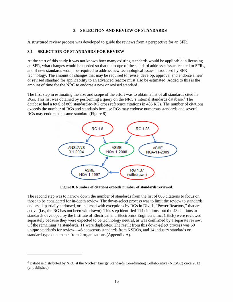
The first step in estimating the size and scope of the effort was to obtain a list of all standards cited in RGs. This list was obtained by performing a query on the NRC’s internal standards database.3 The database had a total of 865 standard-to-RG cross reference citations in 486 RGs. The number of citations exceeds the number of RGs and standards because RGs may endorse numerous standards and several RGs may endorse the same standard (Figure 8).
Figure 8. Number of citations exceeds number of standards reviewed.
The second step was to narrow down the number of standards from the list of 865 citations to focus on those to be considered for in-depth review. The down-select process was to limit the review to standards endorsed, partially endorsed, or endorsed with exceptions by RGs in Div. 1, “Power Reactors,” that are active (i.e., the RG has not been withdrawn). This step identified 114 citations, but the 43 citations to standards developed by the Institute of Electrical and Electronics Engineers, Inc. (IEEE) were reviewed separately because they were expected to be technology neutral, as was confirmed by a separate review. Of the remaining 71 standards, 11 were duplicates. The result from this down-select process was 60 unique standards for review—46 consensus standards from 6 SDOs, and 14 industry standards or standard-type documents from 2 organizations (Appendix A).
3 Database distributed by NRC at the Nuclear Energy Standards Coordinating Collaborative (NESCC) circa 2012 (unpublished).
16
3.2 REVIEW OF STANDARDS
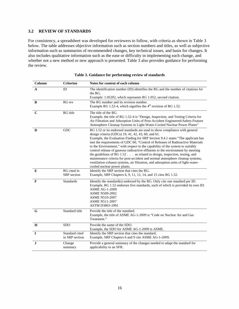
For consistency, a spreadsheet was developed for reviewers to follow, with criteria as shown in Table 3 below. The table addresses objective information such as section numbers and titles, as well as subjective information such as summaries of recommended changes, key technical issues, and basis for changes. It also includes qualitative information such as the ease or difficulty in implementing each change, and whether not a new method or new approach is presented. Table 3 also provides guidance for performing the review.
Table 3. Guidance for performing review of standards
Column Criterion Notes for content of each column
A ID The identification number (ID) identifies the RG and the number of citations for the RG. Example: 1.05202, which represents RG 1.052, second citation.
B RG rev The RG number and its revision number. Example RG 1.52-4, which signifies the 4th revision of RG 1.52.
C RG title The title of the RG. Example, the title of RG 1.52-4 is “Design, Inspection, and Testing Criteria for Air Filtration and Adsorption Units of Post-Accident Engineered-Safety-Feature Atmosphere Cleanup Systems in Light-Water-Cooled Nuclear Power Plants”
D GDC RG 1.52 or its endorsed standards are used to show compliance with general design criteria (GDCs) 19, 41, 42, 43, 60, and 61. Example, the Evaluation Finding for SRP Section 9.4.1 states “The applicant has met the requirements of GDC 60, “Control of Releases of Radioactive Materials to the Environment,” with respect to the capability of the system to suitably control release of gaseous radioactive effluents to the environment by meeting the guidelines of RG 1.52 . . . as related to design, inspection, testing, and maintenance criteria for post-accident and normal atmosphere cleanup systems, ventilation exhaust systems, air filtration, and adsorption units of light-water-cooled nuclear power plants.
E RG cited in SRP section
Identify the SRP section that cites the RG. Example, SRP Chapters 6, 9, 11, 12, 14, and 15 cites RG 1.52.
F Standards Identify the standard(s) endorsed by the RG. Only cite one standard per ID. Example, RG 1.52 endorses five standards, each of which is provided its own ID: ASME AG-1-2009 ASME N509-2002 ASME N510-2007 ASME N511-2007 ASTM D3803-1991
G Standard title Provide the title of the standard. Example, the title of ASME AG-1-2009 is “Code on Nuclear Air and Gas Treatment.”
H SDO Provide the name of the SDO. Example, the SDO for ASME AG-1-2009 is ASME.
I Standard cited in SRP section
Identify the SRP section that cites the standard. Example, SRP Chapters 6 and 9 cite ASME AG-1-2009.
J Change summary
Provide a general summary of the changes needed to adapt the standard for applicability to an SFR.

17
K Level of Effort applies to SFR
Include the number as it applies to each column Change Code: 1 = no changes needed 2 = limited changes needed (e.g., only change terminology) 3 = substantive changes needed 4 = insufficient design info to know how extensive the changes might be 5 = not applicable to the design reviewed 6 = new design-specific requirement to add
L Key technical issues
Summarize what the key technical issues of the standard. Provide the purpose of the standard and what the standard addresses.
M Comments, notes
Specify whether a complete or partial review; include additional notes that might aid in rewriting the section.
3.3 LEVEL OF EFFORT (LOE)
Because this is a pilot program, this review focused on the applicability of the standards to an SFR. It is outside the scope of this review to prioritize the endorsement activities of a standard by NRC, the development activities of an SDO, or to relate the development of a standard to NRC’s mission.
The 60 standards selected for review for applicability to SFRs were categorized in one of five level-of-effort categories:
1. no changes needed (i.e., use standard as-is) 2. limited changes for applicability to SFRs 3. substantive changes needed for applicability to SFRs 4. insufficient design information available 5. not applicable to SFRs
The level-of-effort estimates the significance of the changes to revise a standard for applicability to an SFR and not necessarily the hours needed or the availability of data to revise the standard.
A sixth level of effort was added to track any standards recommended for licensing an SFR.
This section provides examples of the level of effort categorizations. Appendix A provides reviews of all 60 standards endorsed by RGs and the 12 proposed new standards. Information on key technical issues and the comments provided in the following tables and in the Appendices are largely quoted from the referenced standard.
3.3.1 No Changes (LOE 1)
There were 18 standards with limited changes necessary for applicability to an SFR. An excerpt of the changes is shown in Table 4. These standards are technology neutral and would be applicable to any type reactor design.

18
Table 4. SFR review: examples of no changes to standard for applicability (LOE 1)
Standard Change summary Key technical issues
ASME NQA-1-2008 — NQA-1 is a multipart Standard that provides/includes requirements and nonmandatory guidance to establish and implement a QA program for any nuclear facility application. Part I contains QA program requirements for the siting, design, construction, operation, and decommissioning of nuclear facilities. Part II contains QA requirements for the planning and conducting of the fabrication, construction, modification, repair, maintenance, and testing of systems, components, or activities for nuclear facilities. Part III contains nonmandatory guidance. Part IV contains NQA position papers and other quality program information.
ASTM D3843-16 — Quality assurance, as covered in ASTM D3843, comprises all those planned and systematic actions necessary to provide adequate confidence that safety-related coating work in nuclear facilities as defined in ASTM D5144, will perform satisfactorily in service. Safety-related coating work shall be governed by programmatic and procedural quality provisions that ensure the requirements of 10 CFR 50, Appendix B as defined are satisfied.
EPRI 102543 R1
(EPRI 3002002289)
— RG 1.231 endorses EPRI 1025243. However, EPRI 3002002289 supersedes EPRI 1025243. The Level of Effort is based on RG 1.231 endorsing the new EPRI document.
The EPRI Technical Report 1025243 guidance was specifically developed to guide the technical evaluation and acceptance of commercial-grade design and analysis computer programs. It incorporates knowledge of industry standards and operational experience in the formulation of QA guidance supporting both operating nuclear plant operations and upgrades, and new nuclear plant design and construction.
The commercial-grade dedication should be the same for SFRs.
3.3.2 Limited Changes (LOE 2)
There were 16 standards with limited changes necessary for applicability to an SFR. An excerpt of the changes is shown in Table 5. Standards cited as LOE 2 are typically technology neutral; removing the LWR-based terminology (e.g., LWR or DBA) makes that standard applicable to all reactor technologies. To avoid overwhelming an SDO and to prevent scope creep, it is recommended that these standards not be submitted for revision.
19
Table 5. SFR review: examples of limited review comments (LOE 2)
Standard Change summary Key technical issues
ANSI/ANS 3.1-2014 Requirements for experience at a comparable facility and equivalent position will need to be addressed for SRO and RO. Other managerial and staff requirements seem applicable.
The purpose of this standard is to provide guidance for functional levels and job positions as they exist in the operating organization. Qualification requirements include education, experience, and training. This standard provides qualification guidance to meet the particular organizational needs that are derived from the requirements contained in this standard.
ASTM D7167-05 Coating Service Level III lining systems subject to this guide are generally those applied to metal substrates comprising raw water, condensate-quality water, or fuel oil wetted (that is, full or intermittent immersion) surfaces. The establishing procedures to monitor the performance applies to SFRs and the scope should be expanded to include SFRs.
This guide covers procedures for establishing a program to monitor the performance of Coating Service Level III lining (and coating) systems in operating nuclear power plants. Monitoring is an ongoing process of evaluating the condition of the in-service lining systems.
NEI 00-04 The process for evaluating and identifying Risk Informed Safety Classifications (RISC) SSCs is applicable to SFRs. However, the examples are all LWR specific and would have to be updated to provide guidance for SFRs.
The objective of this regulatory initiative is to adjust the scope of equipment subject to special regulatory treatment (controls) to better focus licensee and NRC attention and resources on equipment that has safety significance. This guideline addresses the use of risk insights to define the scope of equipment that should be subject to NRC special treatment provisions as defined in §50.69.
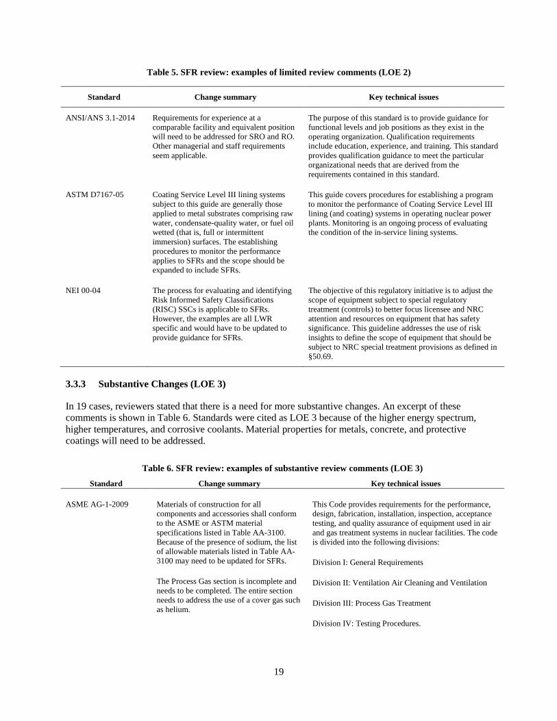
3.3.3 Substantive Changes (LOE 3)
In 19 cases, reviewers stated that there is a need for more substantive changes. An excerpt of these comments is shown in Table 6. Standards were cited as LOE 3 because of the higher energy spectrum, higher temperatures, and corrosive coolants. Material properties for metals, concrete, and protective coatings will need to be addressed.
Table 6. SFR review: examples of substantive review comments (LOE 3)
Standard Change summary Key technical issues
ASME AG-1-2009 Materials of construction for all components and accessories shall conform to the ASME or ASTM material specifications listed in Table AA-3100. Because of the presence of sodium, the list of allowable materials listed in Table AA-3100 may need to be updated for SFRs.
The Process Gas section is incomplete and needs to be completed. The entire section needs to address the use of a cover gas such as helium.
This Code provides requirements for the performance, design, fabrication, installation, inspection, acceptance testing, and quality assurance of equipment used in air and gas treatment systems in nuclear facilities. The code is divided into the following divisions:
Division I: General Requirements
Division II: Ventilation Air Cleaning and Ventilation
Division III: Process Gas Treatment
Division IV: Testing Procedures.
20
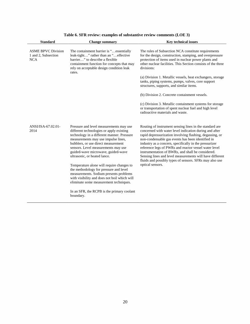
Table 6. SFR review: examples of substantive review comments (LOE 3)
Standard Change summary Key technical issues
ASME BPVC Division 1 and 2, Subsection NCA
The containment barrier is “…essentially leak-tight…” rather than an “…effective barrier…” to describe a flexible containment function for concepts that may rely on acceptable design condition leak rates.
The rules of Subsection NCA constitute requirements for the design, construction, stamping, and overpressure protection of items used in nuclear power plants and other nuclear facilities. This Section consists of the three divisions:
(a) Division 1. Metallic vessels, heat exchangers, storage tanks, piping systems, pumps, valves, core support structures, supports, and similar items.
(b) Division 2. Concrete containment vessels.
(c) Division 3. Metallic containment systems for storage or transportation of spent nuclear fuel and high level radioactive materials and waste.
ANSI/ISA-67.02.01-2014
Pressure and level measurements may use different technologies or apply existing technology in a different manner. Pressure measurements may use impulse lines, bubblers, or use direct measurement sensors. Level measurements may use guided-wave microwave, guided-wave ultrasonic, or heated lance.
Temperature alone will require changes to the methodology for pressure and level measurements. Sodium presents problems with visibility and does not boil which will eliminate some measurement techniques.
In an SFR, the RCPB is the primary coolant boundary.
Routing of instrument sensing lines in the standard are concerned with water level indication during and after rapid depressurization involving flashing, degassing, or non-condensable gas events has been identified in industry as a concern, specifically in the pressurizer reference legs of PWRs and reactor vessel water level instrumentation of BWRs, and shall be considered. Sensing lines and level measurements will have different fluids and possibly types of sensors. SFRs may also use optical sensors.
21
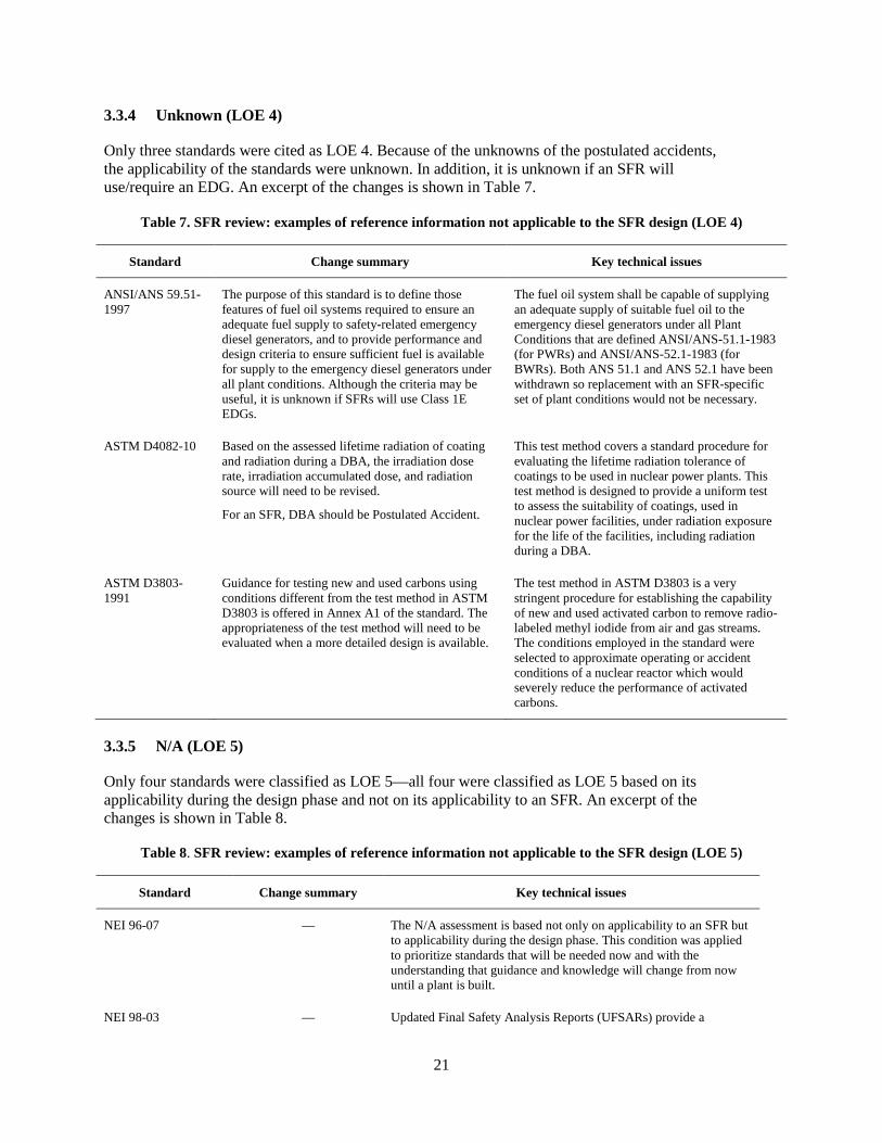
3.3.4 Unknown (LOE 4)
Only three standards were cited as LOE 4. Because of the unknowns of the postulated accidents, the applicability of the standards were unknown. In addition, it is unknown if an SFR will use/require an EDG. An excerpt of the changes is shown in Table 7.
Table 7. SFR review: examples of reference information not applicable to the SFR design (LOE 4)
Standard Change summary Key technical issues
ANSI/ANS 59.51-1997
The purpose of this standard is to define those features of fuel oil systems required to ensure an adequate fuel supply to safety-related emergency diesel generators, and to provide performance and design criteria to ensure sufficient fuel is available for supply to the emergency diesel generators under all plant conditions. Although the criteria may be useful, it is unknown if SFRs will use Class 1E EDGs.
The fuel oil system shall be capable of supplying an adequate supply of suitable fuel oil to the emergency diesel generators under all Plant Conditions that are defined ANSI/ANS-51.1-1983 (for PWRs) and ANSI/ANS-52.1-1983 (for BWRs). Both ANS 51.1 and ANS 52.1 have been withdrawn so replacement with an SFR-specific set of plant conditions would not be necessary.
ASTM D4082-10 Based on the assessed lifetime radiation of coating and radiation during a DBA, the irradiation dose rate, irradiation accumulated dose, and radiation source will need to be revised.
For an SFR, DBA should be Postulated Accident.
This test method covers a standard procedure for evaluating the lifetime radiation tolerance of coatings to be used in nuclear power plants. This test method is designed to provide a uniform test to assess the suitability of coatings, used in nuclear power facilities, under radiation exposure for the life of the facilities, including radiation during a DBA.
ASTM D3803-1991
Guidance for testing new and used carbons using conditions different from the test method in ASTM D3803 is offered in Annex A1 of the standard. The appropriateness of the test method will need to be evaluated when a more detailed design is available.
The test method in ASTM D3803 is a very stringent procedure for establishing the capability of new and used activated carbon to remove radio-labeled methyl iodide from air and gas streams. The conditions employed in the standard were selected to approximate operating or accident conditions of a nuclear reactor which would severely reduce the performance of activated carbons.
3.3.5 N/A (LOE 5)
Only four standards were classified as LOE 5—all four were classified as LOE 5 based on its applicability during the design phase and not on its applicability to an SFR. An excerpt of the changes is shown in Table 8.
Table 8. SFR review: examples of reference information not applicable to the SFR design (LOE 5)
Standard Change summary Key technical issues
NEI 96-07 — The N/A assessment is based not only on applicability to an SFR but to applicability during the design phase. This condition was applied to prioritize standards that will be needed now and with the understanding that guidance and knowledge will change from now until a plant is built.
NEI 98-03 — Updated Final Safety Analysis Reports (UFSARs) provide a
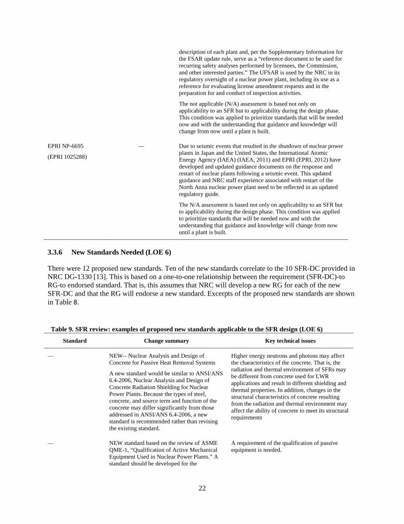
22
description of each plant and, per the Supplementary Information for the FSAR update rule, serve as a “reference document to be used for recurring safety analyses performed by licensees, the Commission, and other interested parties.” The UFSAR is used by the NRC in its regulatory oversight of a nuclear power plant, including its use as a reference for evaluating license amendment requests and in the preparation for and conduct of inspection activities. The not applicable (N/A) assessment is based not only on applicability to an SFR but to applicability during the design phase. This condition was applied to prioritize standards that will be needed now and with the understanding that guidance and knowledge will change from now until a plant is built.
EPRI NP-6695
(EPRI 1025288)
— Due to seismic events that resulted in the shutdown of nuclear power plants in Japan and the United States, the International Atomic Energy Agency (IAEA) (IAEA, 2011) and EPRI (EPRI, 2012) have developed and updated guidance documents on the response and restart of nuclear plants following a seismic event. This updated guidance and NRC staff experience associated with restart of the North Anna nuclear power plant need to be reflected in an updated regulatory guide.
The N/A assessment is based not only on applicability to an SFR but to applicability during the design phase. This condition was applied to prioritize standards that will be needed now and with the understanding that guidance and knowledge will change from now until a plant is built.
3.3.6 New Standards Needed (LOE 6)
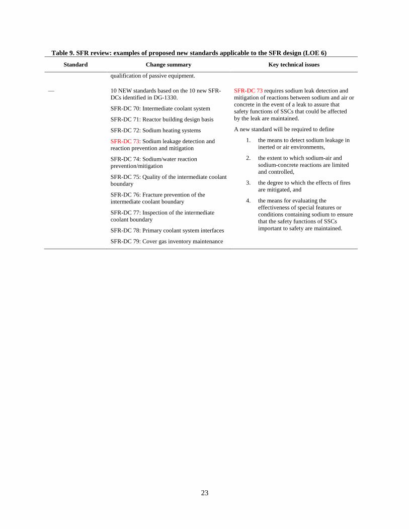
There were 12 proposed new standards. Ten of the new standards correlate to the 10 SFR-DC provided in NRC DG-1330 [13]. This is based on a one-to-one relationship between the requirement (SFR-DC)-to RG-to endorsed standard. That is, this assumes that NRC will develop a new RG for each of the new SFR-DC and that the RG will endorse a new standard. Excerpts of the proposed new standards are shown in Table 8.
Table 9. SFR review: examples of proposed new standards applicable to the SFR design (LOE 6)
Standard Change summary Key technical issues
— NEW-- Nuclear Analysis and Design of Concrete for Passive Heat Removal Systems
A new standard would be similar to ANSI/ANS 6.4-2006, Nuclear Analysis and Design of Concrete Radiation Shielding for Nuclear Power Plants. Because the types of steel, concrete, and source term and function of the concrete may differ significantly from those addressed in ANSI/ANS 6.4-2006, a new standard is recommended rather than revising the existing standard.
Higher energy neutrons and photons may affect the characteristics of the concrete. That is, the radiation and thermal environment of SFRs may be different from concrete used for LWR applications and result in different shielding and thermal properties. In addition, changes in the structural characteristics of concrete resulting from the radiation and thermal environment may affect the ability of concrete to meet its structural requirements
— NEW standard based on the review of ASME QME-1, “Qualification of Active Mechanical Equipment Used in Nuclear Power Plants.” A standard should be developed for the
A requirement of the qualification of passive equipment is needed.
23
Table 9. SFR review: examples of proposed new standards applicable to the SFR design (LOE 6)
Standard Change summary Key technical issues
qualification of passive equipment.
— 10 NEW standards based on the 10 new SFR-DCs identified in DG-1330.
SFR-DC 70: Intermediate coolant system
SFR-DC 71: Reactor building design basis
SFR-DC 72: Sodium heating systems
SFR-DC 73: Sodium leakage detection and reaction prevention and mitigation
SFR-DC 74: Sodium/water reaction prevention/mitigation
SFR-DC 75: Quality of the intermediate coolant boundary
SFR-DC 76: Fracture prevention of the intermediate coolant boundary
SFR-DC 77: Inspection of the intermediate coolant boundary
SFR-DC 78: Primary coolant system interfaces
SFR-DC 79: Cover gas inventory maintenance
SFR-DC 73 requires sodium leak detection and mitigation of reactions between sodium and air or concrete in the event of a leak to assure that safety functions of SSCs that could be affected by the leak are maintained.
A new standard will be required to define
1. the means to detect sodium leakage in inerted or air environments,
2. the extent to which sodium-air and sodium-concrete reactions are limited and controlled,
3. the degree to which the effects of fires are mitigated, and
4. the means for evaluating the effectiveness of special features or conditions containing sodium to ensure that the safety functions of SSCs important to safety are maintained.

25
4. RESULTS
Because this is a pilot program, this review focused on the applicability of the standards to an SFR. It is outside the scope of this review to prioritize the development activities of a standard by NRC or an SDO or to relate its development to the NRC mission.
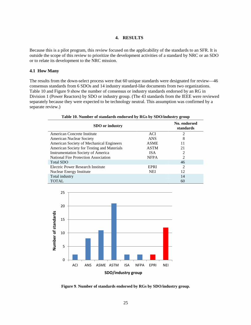
4.1 How Many
The results from the down-select process were that 60 unique standards were designated for review—46 consensus standards from 6 SDOs and 14 industry standard-like documents from two organizations. Table 10 and Figure 9 show the number of consensus or industry standards endorsed by an RG in Division 1 (Power Reactors) by SDO or industry group. (The 43 standards from the IEEE were reviewed separately because they were expected to be technology neutral. This assumption was confirmed by a separate review.)
Table 10. Number of standards endorsed by RGs by SDO/industry group
SDO or industry No. endorsed standards
American Concrete Institute ACI 2 American Nuclear Society ANS 8 American Society of Mechanical Engineers ASME 11 American Society for Testing and Materials ASTM 21 Instrumentation Society of America ISA 2 National Fire Protection Association NFPA 2 Total SDO 46 Electric Power Research Institute EPRI 2 Nuclear Energy Institute NEI 12 Total industry 14 TOTAL 60
Figure 9. Number of standards endorsed by RGs by SDO/industry group.
0
5
10
15
20
25
ACI ANS ASME ASTM ISA NFPA EPRI NEI
Num
ber o
f sta
ndar
ds
SDO/industry group

26
4.2 Amount of Effort Required
Of the 60 standards reviewed about 40% will not require any changes (i.e., no changes (18) or not applicable (4)). The other ~60% of the standards reviewed will require minor changes (16), significant changes (19), or there was insufficient information available to assess the applicability (3) (Table 11 and Figure 10).
Table 11. Level of effort to revise existing standards endorsed by RGs
Level of effort category
Number of standards %
1 18 30 2 16 27 3 19 32 4 3 5 5 4 6
Total 60 100
Figure 10. Level of effort to revise standards.
For the 46 voluntary consensus standards reviewed, about 40% will not require any changes (i.e., no changes [17]). Of the other ~60%, 13 will require minor changes, 13 will require significant changes13, or in three cases, insufficient information available to assess applicability.
For the 14 industry standards-type documents reviewed from EPRI and NEI, about ~35% will not require any changes (i.e., no changes [1] or not applicable [4]). Of the other ~65%, 3 will require minor changes, and 6 will require significant changes.
02468
101214161820
1 2 3 4 5 6
Level of effort new (SDOs)
industry
SDO (no IEEE)
Num
ber o
f sta
ndar
ds
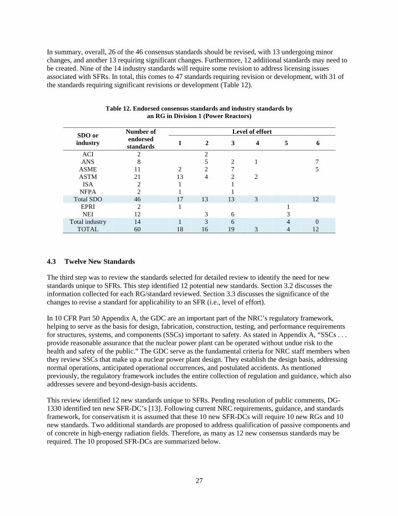
27
In summary, overall, 26 of the 46 consensus standards should be revised, with 13 undergoing minor changes, and another 13 requiring significant changes. Furthermore, 12 additional standards may need to be created. Nine of the 14 industry standards will require some revision to address licensing issues associated with SFRs. In total, this comes to 47 standards requiring revision or development, with 31 of the standards requiring significant revisions or development (Table 12).
Table 12. Endorsed consensus standards and industry standards by an RG in Division 1 (Power Reactors)
SDO or industry
Number of endorsed standards
Level of effort
1 2 3 4 5 6
ACI 2 2 ANS 8 5 2 1 7
ASME 11 2 2 7 5 ASTM 21 13 4 2 2
ISA 2 1 1 NFPA 2 1 1
Total SDO 46 17 13 13 3 12 EPRI 2 1 1 NEI 12 3 6 3
Total industry 14 1 3 6 4 0 TOTAL 60 18 16 19 3 4 12
4.3 Twelve New Standards
The third step was to review the standards selected for detailed review to identify the need for new standards unique to SFRs. This step identified 12 potential new standards. Section 3.2 discusses the information collected for each RG/standard reviewed. Section 3.3 discusses the significance of the changes to revise a standard for applicability to an SFR (i.e., level of effort).
In 10 CFR Part 50 Appendix A, the GDC are an important part of the NRC’s regulatory framework, helping to serve as the basis for design, fabrication, construction, testing, and performance requirements for structures, systems, and components (SSCs) important to safety. As stated in Appendix A, “SSCs . . . provide reasonable assurance that the nuclear power plant can be operated without undue risk to the health and safety of the public.” The GDC serve as the fundamental criteria for NRC staff members when they review SSCs that make up a nuclear power plant design. They establish the design basis, addressing normal operations, anticipated operational occurrences, and postulated accidents. As mentioned previously, the regulatory framework includes the entire collection of regulation and guidance, which also addresses severe and beyond-design-basis accidents.
This review identified 12 new standards unique to SFRs. Pending resolution of public comments, DG-1330 identified ten new SFR-DC’s [13]. Following current NRC requirements, guidance, and standards framework, for conservatism it is assumed that these 10 new SFR-DCs will require 10 new RGs and 10 new standards. Two additional standards are proposed to address qualification of passive components and of concrete in high-energy radiation fields. Therefore, as many as 12 new consensus standards may be required. The 10 proposed SFR-DCs are summarized below.
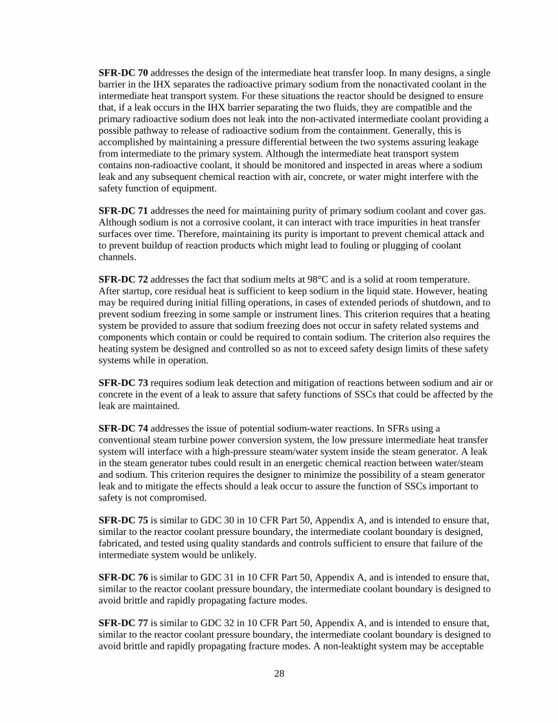
28
SFR-DC 70 addresses the design of the intermediate heat transfer loop. In many designs, a single barrier in the IHX separates the radioactive primary sodium from the nonactivated coolant in the intermediate heat transport system. For these situations the reactor should be designed to ensure that, if a leak occurs in the IHX barrier separating the two fluids, they are compatible and the primary radioactive sodium does not leak into the non-activated intermediate coolant providing a possible pathway to release of radioactive sodium from the containment. Generally, this is accomplished by maintaining a pressure differential between the two systems assuring leakage from intermediate to the primary system. Although the intermediate heat transport system contains non-radioactive coolant, it should be monitored and inspected in areas where a sodium leak and any subsequent chemical reaction with air, concrete, or water might interfere with the safety function of equipment.
SFR-DC 71 addresses the need for maintaining purity of primary sodium coolant and cover gas. Although sodium is not a corrosive coolant, it can interact with trace impurities in heat transfer surfaces over time. Therefore, maintaining its purity is important to prevent chemical attack and to prevent buildup of reaction products which might lead to fouling or plugging of coolant channels.
SFR-DC 72 addresses the fact that sodium melts at 98°C and is a solid at room temperature. After startup, core residual heat is sufficient to keep sodium in the liquid state. However, heating may be required during initial filling operations, in cases of extended periods of shutdown, and to prevent sodium freezing in some sample or instrument lines. This criterion requires that a heating system be provided to assure that sodium freezing does not occur in safety related systems and components which contain or could be required to contain sodium. The criterion also requires the heating system be designed and controlled so as not to exceed safety design limits of these safety systems while in operation.
SFR-DC 73 requires sodium leak detection and mitigation of reactions between sodium and air or concrete in the event of a leak to assure that safety functions of SSCs that could be affected by the leak are maintained.
SFR-DC 74 addresses the issue of potential sodium-water reactions. In SFRs using a conventional steam turbine power conversion system, the low pressure intermediate heat transfer system will interface with a high-pressure steam/water system inside the steam generator. A leak in the steam generator tubes could result in an energetic chemical reaction between water/steam and sodium. This criterion requires the designer to minimize the possibility of a steam generator leak and to mitigate the effects should a leak occur to assure the function of SSCs important to safety is not compromised.
SFR-DC 75 is similar to GDC 30 in 10 CFR Part 50, Appendix A, and is intended to ensure that, similar to the reactor coolant pressure boundary, the intermediate coolant boundary is designed, fabricated, and tested using quality standards and controls sufficient to ensure that failure of the intermediate system would be unlikely.
SFR-DC 76 is similar to GDC 31 in 10 CFR Part 50, Appendix A, and is intended to ensure that, similar to the reactor coolant pressure boundary, the intermediate coolant boundary is designed to avoid brittle and rapidly propagating facture modes.
SFR-DC 77 is similar to GDC 32 in 10 CFR Part 50, Appendix A, and is intended to ensure that, similar to the reactor coolant pressure boundary, the intermediate coolant boundary is designed to avoid brittle and rapidly propagating fracture modes. A non-leaktight system may be acceptable

29
for some designs provided that (1) the system leakage does not impact safety functions under all conditions, and (2) defense in depth is not impacted by system leakage.
SFR-DC 78 addresses the consequence of leakage between the primary coolant system and a heat removal system (i.e. RHR system, intermediate coolant system) is more significant for primary coolant system (potentially impacting the fuel design limits or integrity of the primary coolant boundary) than it is for the heat removal system (coolant drawdown or introduction of radioactive sodium).
SFR-DC 79 is similar to GDC 33 in 10 CFR Part 50, Appendix A and SFR-DC 33 in this document. GDC 33 and SFR-DC 33 focus on the effects of primary coolant (sodium) loss. A leak in a SFR primary coolant system may expel the cover gas rather than the primary coolant. The cover gas in the SFR performs an important safety function by protecting the sodium coolant from chemical reactions. The staff created a new SFR-DC rather than adding the cover gas in the term “primary coolant.” The term “primary coolant sodium design limits” is used to maintain consistent terminology with SFR-DC 71. The primary coolant sodium design limits consider the possibility of interactions between the primary coolant sodium and the primary coolant boundary or the fuel due to changes in the chemistry of the primary coolant sodium. The considerations include the possibility of (1) chemical attack, (2) fouling and plugging of passages, (3) radionuclide concentrations, and (4) air or moisture ingress as a result of a leak of cover gas.
Two additional standards are proposed to address qualification of passive components and of concrete in high-energy radiation fields:
A requirement of the qualification of passive equipment is needed to address the nuclear analysis and design of passive heat removal systems, such as the concrete for passive heat removal. This new standard would be similar to ASME QME-1, Qualification of Active Mechanical Equipment Used in Nuclear Power Plants that provides the requirements and guidelines for the qualification of active mechanical equipment whose function is required to ensure the safe operation or safe shutdown of a nuclear facility. A similar standard should be developed for the qualification of passive equipment whose function is required to ensure the safe operation or safe shutdown.
A new standard would be similar to ANSI/ANS 6.4-2006, Nuclear Analysis and Design of Concrete Radiation Shielding for Nuclear Power Plants. Because the types of steel, concrete, and source term and function of the concrete4 may differ significantly from those addressed in ANSI/ANS 6.4-2006, a new standard is recommended rather than revising the existing standard.
4.4 SDO and Industry Involvement
Of the SDOs with standards endorsed by an RG, all of the SDOs (except EPRI5) must be involved in revising or developing at least one standard for applicability to an SFR (Figure 11). With respect to those
4 The passive heat transfer system in an SFR transfers the heat generated in the core to the sodium coolant, which increases the temperature of the reactor vessel wall. The heat from the reactor vessel wall is radiated to the containment vessel wall across the argon gas-filled gap between the reactor vessel and the containment vessel. As the reactor vessel wall temperature increases, radiant heat transfer between the reactor vessel wall and the containment wall increases rapidly. The containment vessel wall is cooled by the circulation of outside air. This passive system is always in operation.
5 EPRI had standards cited as LOE 1—no changes and LOE 5—N/A.
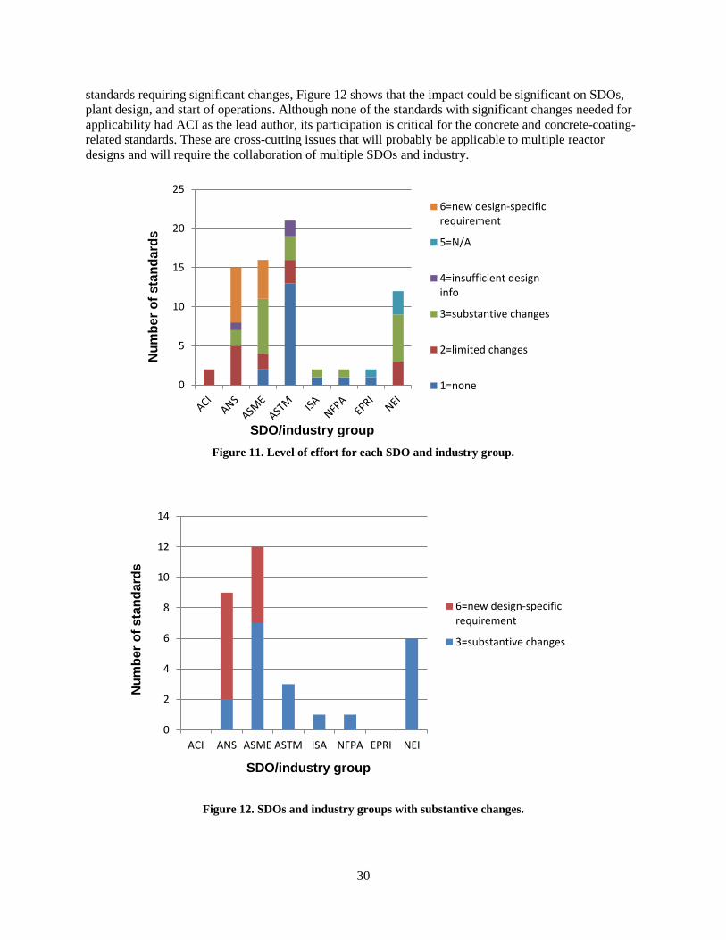
30
standards requiring significant changes, Figure 12 shows that the impact could be significant on SDOs, plant design, and start of operations. Although none of the standards with significant changes needed for applicability had ACI as the lead author, its participation is critical for the concrete and concrete-coating-related standards. These are cross-cutting issues that will probably be applicable to multiple reactor designs and will require the collaboration of multiple SDOs and industry.
Figure 11. Level of effort for each SDO and industry group.
Figure 12. SDOs and industry groups with substantive changes.
0
5
10
15
20
256=new design-specificrequirement
5=N/A
4=insufficient designinfo
3=substantive changes
2=limited changes
1=none
0
2
4
6
8
10
12
14
ACI ANS ASME ASTM ISA NFPA EPRI NEI
6=new design-specificrequirement
3=substantive changes
Num
ber o
f sta
ndar
ds
SDO/industry group
Num
ber o
f sta
ndar
ds
SDO/industry group
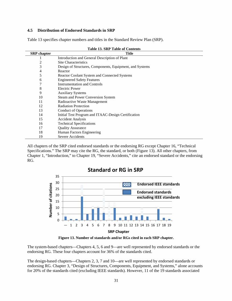
31
4.5 Distribution of Endorsed Standards in SRP
Table 13 specifies chapter numbers and titles in the Standard Review Plan (SRP).
Table 13. SRP Table of Contents SRP chapter Title
1 Introduction and General Description of Plant 2 Site Characteristics 3 Design of Structures, Components, Equipment, and Systems 4 Reactor 5 Reactor Coolant System and Connected Systems 6 Engineered Safety Features 7 Instrumentation and Controls 8 Electric Power 9 Auxiliary Systems 10 Steam and Power Conversion System 11 Radioactive Waste Management 12 Radiation Protection 13 Conduct of Operations 14 Initial Test Program and ITAAC-Design Certification 15 Accident Analysis 16 Technical Specifications 17 Quality Assurance 18 Human Factors Engineering 19 Severe Accidents
All chapters of the SRP cited endorsed standards or the endorsing RG except Chapter 16, “Technical Specifications.” The SRP may cite the RG, the standard, or both (Figure 13). All other chapters, from Chapter 1, “Introduction,” to Chapter 19, “Severe Accidents,” cite an endorsed standard or the endorsing RG.
Figure 13. Number of standards and/or RGs cited in each SRP chapter.
The system-based chapters—Chapters 4, 5, 6 and 9—are well represented by endorsed standards or the endorsing RG. These four chapters account for 36% of the standards cited.
The design-based chapters—Chapters 2, 3, 7 and 10—are well represented by endorsed standards or endorsing RG. Chapter 3, “Design of Structures, Components, Equipment, and Systems,” alone accounts for 20% of the standards cited (excluding IEEE standards). However, 11 of the 19 standards associated
0
5
10
15
20
25
30
35
— 1 2 3 4 5 6 7 8 9 10 11 12 13 14 15 16 17 18 19
Standard or RG in SRP
Endorsed IEEE standards
Endorsed standards excluding IEEE standards
SRP Chapter
Num
ber o
f cita
tions
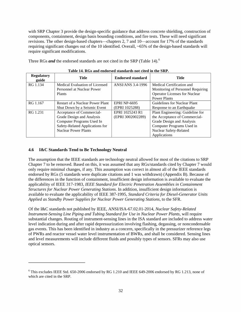
32
with SRP Chapter 3 provide the design-specific guidance that address concrete shielding, construction of components, containment, design basis bounding conditions, and fire tests. These will need significant revisions. The other design-based chapters—chapters 2, 7 and 10—account for 17% of the standards requiring significant changes out of the 10 identified. Overall, ~65% of the design-based standards will require significant modifications.
Three RGs and the endorsed standards are not cited in the SRP (Table 14).6
Table 14. RGs and endorsed standards not cited in the SRP. Regulatory
guide Title Endorsed standard Title
RG 1.134 Medical Evaluation of Licensed Personnel at Nuclear Power Plants
ANSI/ANS 3.4-1996 Medical Certification and Monitoring of Personnel Requiring Operator Licenses for Nuclear Power Plants
RG 1.167 Restart of a Nuclear Power Plant Shut Down by a Seismic Event
EPRI NP-6695 (EPRI 1025288)
Guidelines for Nuclear Plant Response to an Earthquake
RG 1.231 Acceptance of Commercial-Grade Design and Analysis Computer Programs Used In Safety-Related Applications for Nuclear Power Plants
EPRI 1025243 R1 (EPRI 3002002289)
Plant Engineering: Guideline for the Acceptance of Commercial-Grade Design and Analysis Computer Programs Used in Nuclear Safety-Related Applications
4.6 I&C Standards Tend to Be Technology Neutral
The assumption that the IEEE standards are technology neutral allowed for most of the citations to SRP Chapter 7 to be removed. Based on this, it was assumed that any RGs/standards cited by Chapter 7 would only require minimal changes, if any. This assumption was correct in almost all of the IEEE standards endorsed by RGs (5 standards were duplicate citations and 1 was withdrawn) (Appendix B). Because of the differences in the function of containment, insufficient design information is available to evaluate the applicability of IEEE 317-1983, IEEE Standard for Electric Penetration Assemblies in Containment Structures for Nuclear Power Generating Stations. In addition, insufficient design information is available to evaluate the applicability of IEEE 387-1995, Standard Criteria for Diesel-Generator Units Applied as Standby Power Supplies for Nuclear Power Generating Stations, to the SFR.
Of the I&C standards not published by IEEE, ANSI/ISA-67.02.01-2014, Nuclear Safety-Related Instrument-Sensing Line Piping and Tubing Standard for Use in Nuclear Power Plants, will require substantial changes. Routing of instrument-sensing lines in the ISA standard are included to address water level indication during and after rapid depressurization involving flashing, degassing, or noncondensable gas events. This has been identified in industry as a concern, specifically in the pressurizer reference legs of PWRs and reactor vessel water level instrumentation of BWRs, and shall be considered. Sensing lines and level measurements will include different fluids and possibly types of sensors. SFRs may also use optical sensors.
6 This excludes IEEE Std. 650-2006 endorsed by RG 1.210 and IEEE 649-2006 endorsed by RG 1.213, none of which are cited in the SRP.
33
Changes necessary for applicability to SFRs for ISA-67.02.01-2014 include:
• Pressure and level measurements may use different technologies, or they may apply existing technology in a different manner. Pressure measurements may use impulse lines, bubblers, or direct measurement sensors. Level measurements may use guided-wave microwave, guided-wave ultrasonic, or heated lance.
• Temperature alone will require changes to the methodology for pressure and level measurements. Sodium presents problems with visibility and does not boil, which will eliminate some measurement techniques.
• In an SFR, the reactor coolant pressure boundary (RCPB) is the primary coolant boundary.
4.7 Applicability to Other SFR Designs
Spreadsheets documenting the review and recommended changes of standards from the SFR perspective (Appendix A) will require similar changes for applicability to the other types of advanced reactor designs.
4.8 Summary of Results
Of the 60 voluntary consensus standards and industry standards endorsed by RGs reviewed, 19 will likely need substantive changes. These 19 standards address the following topic areas:
• Protective coatings and test methods for protective coatings may differ • Temperatures in SFRs may exceed concrete and steel limits in standards • Types of steel, concrete, and source terms may differ greatly for SFRs compared to LWRs • Those components required to function during a DBA (PA) will be different for SFRs and will
require modification to some standards (e.g., seismic, dynamic qualifications) • Containments will be different from current plants • Fire issues (fire-induced failures, testing, etc.) will differ • Presence of sodium affects environmental qualification, habitability, fire, …
Twelve new consensus standards will be required for the following areas:
• 10 SFR-DCs (70–79) identified in DG-1330 • Passive cooling • Passive equipment
The IEEE standards are technology neutral.

34

35
5. SDO APPROVAL AND NRC ENDORSEMENT OF CONSENSUS STANDARDS
Industry and NRC have shown interest in leveraging standards to accelerate licensing of advanced non-LWRs [14]. This strategy depends on forming a group of volunteers to serve as a “coalition of the willing” composed of end user organizations, SDO representatives, NRC representatives, and other stakeholders. One lesson learned in the development of standards is the problem of not having a true champion to help plan a roadmap for the development of a standard (i.e., technical basis, intended standard, RG, schedule).
5.1 SDO Approval
The basic development process for a new standard or the process of revising an existing standard, although it differs for each SDO, has the following steps:
1. Submit a need (and justification) for a new (revised standard) a. Include background information b. Explain the significance of the revisions
2. Prepare a draft standard or revision of an existing document for internal review and comment 3. Revise standard based on internal reviews and issue first draft report
a. Committee approves document for public comment 4. Issue draft for public comment 5. Revise standard based on public comments and issue revised draft
a. Submission of committee approved responses to public comments 6. Submission of revised standard to standards Board 7. Approval of standard for use by Board
Based on a review of the standards development process [15, 16] and a survey of the seven SDOs with standards endorsed by an RG (including ANSI), a range of time periods for development or modification is estimated as follows:
1. Time for minor changes to a standard to be approved: 0.5–2 years 2. Time for significant changes to a standard to be approved: 1–3 years 3. Time for the development and approval of a new standard: 2–8 years
However, ASTM states that depending on a committee’s commitment to timely development and approval, “standards can take as little as nine months to become full consensus standards” [17].
There are many variables that can impact the time to develop or modify a standard such as [18]:
• which committee(s) are involved in the approval process • the technical complexity of the standard • whether any research is needed to support a revision • whether there is a strong champion for the revision or new standard • how many other significant revisions are being considered by the committee(s) in the time frame,
etc.
Any modification or creation of a new standard would benefit from interactions with NRC staff members throughout the development/modification process [14, 19].
36
After it is certified as a full consensus standard, the standard may be forwarded to ANSI for review. Standard development is a rigorous consensus process that for many SDOs has been approved by the American National Standards Institute (ANSI). ANSI is a private, nonprofit organization that administers and coordinates the US voluntary standards and conformity assessment system. ANSI Standard is technically a misnomer, because ANSI does not develop the standards. ANSI Standards are actually developed by one of the ANSI-accredited 230+ SDOs , and then they are approved by ANSI’s Board of Standards Review (BSR) as meeting certain criteria for openness, balance, due process, and consensus in standards development [20].
ANSI verification does not include any evaluation or review of the standard. ANSI audits the SDO to ensure that complete records are retained and that the records fully substantiate the decision to certify that due process was achieved. Proposals for new American National Standards and proposals to revise, reaffirm, or withdraw approval of existing American National Standards undergo a public comment period of 30–60 days. A revised standard based on public comments should be submitted to ANSI within one (1) year from the close of the comment period.
5.2 NRC ENDORSEMENT
As the NRC prepares to review and regulate a new generation of non-LWRs, a vision and strategy has been developed to assure NRC readiness to efficiently and effectively conduct its mission for these technologies [5]. One of NRC’s near term strategies (i.e., 0–5 years) is to “Facilitate industry codes and standards needed to support the non-LWR life cycle (including fuels and materials)” [19].
Contributing activities for the near term include [21, 22]:
• Work with stakeholders to determine the currently available codes and standards applicable to non-LWRs and their associated fuels and waste and to identify the technical areas
• Participate with the SDOs in developing codes and standards for non-LWRs • Review codes and standards for endorsement
The NRC’s mid- and long-term action plans developed as part of the NRC non-LWR implementation action plans (IAPs) recognize that it has typically taken years to develop consensus codes and standards and to promulgate a new or revised regulation [6]. Contributing activities for mid- and long-term activities include:
• Continue efforts to facilitate development of industry codes and standards • Develop RGs and conduct rulemaking, as needed, to endorse industry codes and standards
The outcome from these activities is to have available consensus codes and standards endorsed by the NRC to improve the effectiveness and efficiency of the licensing and regulation of non-LWR technologies. However, the NRC’s endorsement of codes and standards—in either regulations or guidance—can only follow the development and issuance of the codes and standards by SDOs.
The NRC’s endorsement process is described in Management Directive (MD) 6.5 [2, 3], which states that NRC’s participation in the development and use of consensus standards consists of three steps:
1. Identifying and prioritizing needed new and revised technical standards 2. Participation in codes and standards development 3. Endorsement of codes and standards
37
In the case of a new consensus standard, MD 6.5 states that “it is preferable to determine how the consensus standard is to be used before the consensus standard is written.”
NRC endorses consensus standards through incorporation by reference in regulations and through reference in such documents as RGs, NUREG reports, and the SRP. MD 6.6 describes the method used to endorse standards and the process for issuing a RG [23]. The process and timing of a standard being incorporated into a regulation or being approved as guidance is not addressed in this review.


39
6. FUTURE WORK
This pilot project represents a first look at the magnitude of work required to use standards in the design and licensing of SFRs. This pilot project shows that 26 of the 46 consensus standards endorsed by RGs could be revised, but only 13 of those would require significant revisions. Nine of the 14 industry standards endorsed by RGs could require some revision to address licensing issues associated with SFRs but only 6 would require significant revision. 12 additional standards should also be considered to be created. In total, this comes to 47 standards, 31 of which require significant changes or to be created.
A prioritization must be developed for ranking the standards. In terms of advanced reactor licensing, the 12 new standards should be a priority, with those standards requiring significant changes being a close second. In addition, requests must be submitted using a staggered schedule to prevent overwhelming an SDO. Related to this is consideration of standards that require coordination between SDOs or between an SDO and industry. Prioritization should consider those standards that address cross-cutting topics (i.e., applicability to several advance reactor designs). Delays in addressing these changes will directly affect the licensing timeline and commercial deployment.
This pilot project reviewed only those standards endorsed by RGs. All of the standards that provide an acceptable method for meeting NRC regulations are not endorsed in RGs. For example, the section entitled “Acceptance Criteria” in SRP Section 4.2 states the following:
American Nuclear Society (ANS) 5.4 presents an approved method for release during non-LOCAs and situations that do not involve accidents in which the fuel temperature exceeds the temperature experienced during normal operation and AOOs. ANS 5.4 also provides an acceptable analytical model for calculating the release of volatile fission products from oxide fuel pellets during normal steady-state conditions.
Thus, ANS 5.4 provides an approved method for meeting the requirements of 10 CFR 100, but it is not endorsed by an RG, and it is not included in the 60 standards that were reviewed. The number of standards approved by the SRP but not selected through the RG process was not quantified in this pilot program.7 This limitation in the pilot project will have an effect on licensing non-LWRs because of the gap that exists in the use of standards to support licensing a non-LWR.
Consensus standards are also promulgated through the Code of Federal Regulations (CFR) (Table 15). Standards within the CFR have not been identified nor reviewed for applicability to SFRs.
7 Not all industry standards cited in the SRP are endorsed by the NRC. If a standard is not endorsed, the SRP does not include the associated year of the standard.
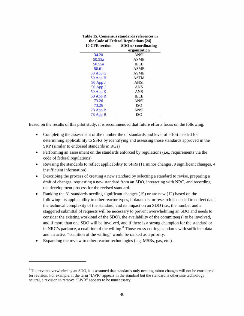
40
Table 15. Consensus standards references in
the Code of Federal Regulations [24] 10 CFR section SDO or coordinating
organization 34.20 ANSI 50.55a ASME 50.55a IEEE 50.61 ASME
50 App G ASME 50 App H ASTM 50 App J ANSI 50 App J ANS 50 App K ANS 50 App R IEEE
73.26 ANSI 73.26 ISO
73 App B ANSI 73 App B ISO
Based on the results of this pilot study, it is recommended that future efforts focus on the following:
• Completing the assessment of the number the of standards and level of effort needed for determining applicability to SFRs by identifying and assessing those standards approved in the SRP (similar to endorsed standards in RGs)
• Performing an assessment on the standards enforced by regulations (i.e., requirements via the code of federal regulations)
• Revising the standards to reflect applicability to SFRs (11 minor changes, 9 significant changes, 4 insufficient information)
• Describing the process of creating a new standard by selecting a standard to revise, preparing a draft of changes, requesting a new standard from an SDO, interacting with NRC, and recording the development process for the revised standard.
• Ranking the 31 standards needing significant changes (19) or are new (12) based on the following: its applicability to other reactor types, if data exist or research is needed to collect data, the technical complexity of the standard, and its impact on an SDO (i.e., the number and a staggered submittal of requests will be necessary to prevent overwhelming an SDO and needs to consider the existing workload of the SDO), the availability of the committee(s) to be involved, and if more than one SDO will be involved, and if there is a strong champion for the standard or in NRC’s parlance, a coalition of the willing.8 Those cross-cutting standards with sufficient data and an active “coalition of the willing” would be ranked as a priority.
• Expanding the review to other reactor technologies (e.g. MSRs, gas, etc.)
8 To prevent overwhelming an SDO, it is assumed that standards only needing minor changes will not be considered for revision. For example, if the term “LWR” appears in the standard but the standard is otherwise technology neutral, a revision to remove “LWR” appears to be unnecessary.
41
It is expected that the use of codes and standards will be an integral part of the NRC’s strategy to improve its readiness to regulate non-LWR technologies. If a consensus standard is not available, then NRC can create its own guidance, and if a standard is available then NRC must justify why it is not being used. There is a great advantage to industry to create the standards rather than to have a standard or guidance imposed. Regardless, advanced reactor technology licensing and deployment will likely be significantly delayed if applicable and endorsed standards are not available for use by both technology developers and the NRC. Delays in providing the NRC with the knowledge base and tools for reviewing non-LWR applications will increase the effort needed to review an application, thus delaying its approval.
Designs can proceed without approved standards, but the benefits of approved standards include their ability to aid in obtaining multiple licensees. The use of standards is an integral part of the NRC’s strategy to improve its readiness to regulate non-LWR technologies (IAP).

43
7. REFERENCES
1. Executive Office of The President, Office of Management and Budget, OMB Circular A-119: Federal Participation in the Development and Use of Voluntary Consensus Standards and in Conformity Assessment Activities, January 27, 2016.
2. MD 6.5, NRC Participation in the Development and use of Consensus Standards, Approved 10/28/2016.
3. Kurt Cozens, “Revised MD 6.5, "NRC Participation in the Development and Use of Consensus Standards,” NRC Standards Forum, September 8, 2016 (ML16246A030).
4. SECY-08-0140, Development and Regulatory Application of Consensus Standards by U.S. Nuclear Regulatory Commission Staff, September 24, 2008.
5. NRC Vision and Strategy: Safely Achieving Effective and Efficient Non-Light Water Reactor Mission Readiness, December 2016. (ML16356A670)
6. Draft, NRC Advanced Reactor Vision and Strategy: Mid-Term and Long-Term Implementation Action Plans (ML17054D483).
7. US Nuclear Regulatory Commission, Policy Statement on the Regulation of Advanced Reactors (73 Fed. Reg. 60612, October 14, 2008).
8. General Electric, PRISM – Preliminary Safety Information Document, GEFR-00793, UC-87Ta, San Jose, CA, 1987.
9. US Nuclear Regulatory Commission, Preapplication Safety Evaluation Report for the Sodium Advanced Fast Reactor (SAFR) Liquid-Metal Reactor, NUREG-1369, December 1991, ML063410561.
10. C. Boardman, et al., “Containment Performance of S-PRISM under Severe Beyond Design Basis Conditions,” 9th International Conference on Nuclear Engineering, Paris, France, April 2001.
11. C. Boardman, et al., GE Nuclear Energy Division, “A Description of the S-PRISM Plant,” 8th International Conference on Nuclear Engineering, Baltimore, MD, April 2000.
12. Idaho National Laboratory Guidance for Developing Principal Design Criteria for Advanced (Non-Light Water) Reactors,” INL/EXT-14-31179, Revision 1, December 2014.
13. DG–1330, ‘Guidance for Developing Principal Design Criteria for Non-Light Water Reactors,’ February 2017.
14. T. Boyce, US NRC, “NRC Standards Forum Overview,” NRC Standards Forum, September 8, 2016.
15. 2017 NFPA Standards Directory, http://www.nfpa.org/~/media/files/codes-and-standards/regulations-directory-and-forms/nfpa_standards_directory_2017.pdf?la=en
16. An Introduction to the NFPA Standards Development Process, http://www.nfpa.org/~/media/files/codes-and-standards/regulations-directory-and-forms/codesstandardsbrochure_2016.pdf?la=en
17. Standards Developed in ASTM International, https://www.astm.org/ABOUT/faqs.html#init 18. E-mail from W. Berger, Managing Director, Standards, ASME to M. D. Muhlheim, ORNL, June
19, 2017. 19. US NRC, Public Meeting on Advanced, Non-light water Reactor Regulatory Reviews, Office of
New Reactors, October 25, 2016. 20. http://webstore.ansi.org/faq.aspx 21. “NRC Non-Light Water Reactor (Non-LWR) Vision and Strategy - Staff Report: Near-Term
Implementation Action Plans,” Volume 1 – Executive Information (ML16294A181). 22. “NRC Non-Light Water Reactor (Non-LWR) Vision and Strategy - Staff Report: Near-Term
Implementation Action Plans,” Volume 2 – Detailed Information (ML16334A495). 23. MD 6.6, Regulatory Guides, 05/02/2016. 24. http://www.nrc.gov/about-nrc/regulatory/standards-dev/consensus.html#rg

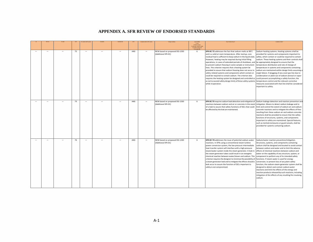
A-1
APPENDIX A. SFR REVIEW OF ENDORSED STANDARDS
ID RG-Rev RG title GDC RG cited in SRP section Standards Standard title SDO Standard cited in SRP section Change Summary Level of Effort 1=none
2=limited changes 3=substantive changes needed
4=insufficient design info 5=not applicable
Key Technical Issues* Comments, Notes*
— — — 72 — — — ANS — NEW based on proposed DG-1330 (Additional SFR-DC)
6 SFR-DC 72 addresses the fact that sodium melts at 98°C and is a solid at room temperature. After startup, core residual heat is sufficient to keep sodium in the liquid state. However, heating may be required during initial filling operations, in cases of extended periods of shutdown, and to prevent sodium freezing in some sample or instrument lines. This criterion requires that a heating system be provided to assure that sodium freezing does not occur in safety related systems and components which contain or could be required to contain sodium. The criterion also requires the heating system be designed and controlled so as not to exceed safety design limits of these safety systems while in operation.
Sodium heating systems. Heating systems shall be provided for systems and components important to safety, which contain or could be required to contain sodium. These heating systems and their controls shall be appropriately designed to ensure that the temperature distribution and rate of change of temperature in systems and components containing sodium are maintained within design limits assuming a single failure. If plugging of any cover gas line due to condensation or plate out of sodium aerosol or vapor could prevent accomplishing a safety function, the temperature control and the relevant corrective measures associated with that line shall be considered important to safety.
— — — 73 — — — ANS — NEW based on proposed DG-1330 (Additional SFR-DC)
6 SFR-DC 73 requires sodium leak detection and mitigation of reactions between sodium and air or concrete in the event of a leak to assure that safety functions of SSCs that could be affected by the leak are maintained.
Sodium leakage detection and reaction prevention and mitigation. Means to detect sodium leakage and to limit and control the extent of sodium-air and sodium- concrete reactions and to mitigate the effects of fires resulting from these sodium-air and sodium-concrete reactions shall be provided to ensure that the safety functions of structures, systems, and components important to safety are maintained. Special features, such as inerted enclosures or guard vessels, shall be provided for systems containing sodium.
— — — 74 — — — ANS — NEW based on proposed DG-1330 (Additional SFR-DC)
6 SFR-DC 74 addresses the issue of potential sodium-water reactions. In SFRs using a conventional steam turbine power conversion system, the low pressure intermediate heat transfer system will interface with a high pressure steam/water system inside the steam generator. A leak in the steam generator tubes could result in an energetic chemical reaction between water/steam and sodium. This criterion requires the designer to minimize the possibility of a steam generator leak and to mitigate the effects should a leak occur to assure the function of SSCs important to safety is not compromised.
Sodium/water reaction prevention/mitigation. Structures, systems, and components containing sodium shall be designed and located to avoid contact between sodium and water and to limit the adverse effects of chemical reactions between sodium and water on the capability of any structure, system, or component to perform any of its intended safety functions. If steam-water is used for energy conversion, to prevent loss of any plant safety function, the sodium-steam generator system shall be designed to detect and contain sodium-water reactions and limit the effects of the energy and reaction products released by such reactions, including mitigation of the effects of any resulting fire involving sodium.

A-2
ID RG-Rev RG title GDC RG cited in SRP section Standards Standard title SDO Standard cited in SRP section Change Summary Level of Effort 1=none
2=limited changes 3=substantive changes needed
4=insufficient design info 5=not applicable
Key Technical Issues Comments, Notes
— — — 78 — — — ANS — NEW based on proposed DG-1330 (Additional SFR-DC)
6 SFR-DC 78 addresses the consequence of leakage between the primary coolant system and a heat removal system (i.e. RHR system, intermediate coolant system) is more significant for primary coolant system (potentially impacting the fuel design limits or integrity of the primary coolant boundary) than it is for the heat removal system (coolant drawdown or introduction of radioactive sodium).
Primary Coolant System Interfaces When the primary coolant system interfaces with a structure, system, or component containing fluid that is chemically incompatible with the primary coolant, the interface location shall be designed to ensure that the primary coolant is separated from the chemically incompatible fluid by two redundant, passive barriers. When the primary coolant system interfaces with a structure, system, or component containing fluid that is chemically compatible with the primary coolant, then the interface location may be a single passive barrier provided that the following conditions are met: (1) postulated leakage at the interface location does not result in failure of the intended safety functions of structures, systems or components important to safety or result in exceeding the fuel design limits (2) the fluid contained in the structure, system, or component is maintained at a higher pressure than the primary coolant during normal operation, AOOs, shutdown, and accident conditions.
— — — 79 — — — ANS — NEW based on proposed DG-1330 (Additional SFR-DC) RG 1.206 cites GDC 33, reactor coolant piping SRP 5, 7, 8,9 cite GDC 33
6 SFR-DC 79 is similar to GDC 33 in 10 CFR Part 50, Appendix A and SFR-DC 33 in this document. GDC 33 and SFR-DC 33 focus on the effects of primary coolant (sodium) loss. A leak in a SFR primary coolant system may expel the cover gas rather than the primary coolant. The cover gas in the SFR performs an important to safety function by protecting the sodium coolant from chemical reactions. The staff created a new SFR-DC rather than adding the cover gas in the term “primary coolant.” The term “primary coolant sodium design limits” is used to maintain consistent terminology with SFR-DC 71. The primary coolant sodium design limits consider the possibility of interactions between the primary coolant sodium and the primary coolant boundary or the fuel due to changes in the chemistry of the primary coolant sodium. The considerations include the possibility of (1) chemical attack, (2) fouling and plugging of passages, (3) radionuclide concentrations, and (4) air or moisture ingress as a result of a leak of cover gas.
Cover gas inventory maintenance. A system to maintain cover gas inventory shall be provided as necessary to ensure that the primary coolant sodium design limits are not exceeded as a result of cover gas loss due to leakage from the primary coolant boundary and rupture of small piping or other small components that are part of the primary coolant boundary.
— — — — — — — ANS — NEW-- Nuclear Analysis and Design of Concrete for Passive Heat Removal Systems
6 Higher energy neutrons and photons may affect the characteristics of the concrete. That is, the radiation and thermal environment of SFRs may be different from concrete used for LWR applications and result in different shielding and thermal properties. In addition, changes in the structural characteristics of concrete resulting from the radiation and thermal environment may affect the ability of concrete to meet its structural requirements
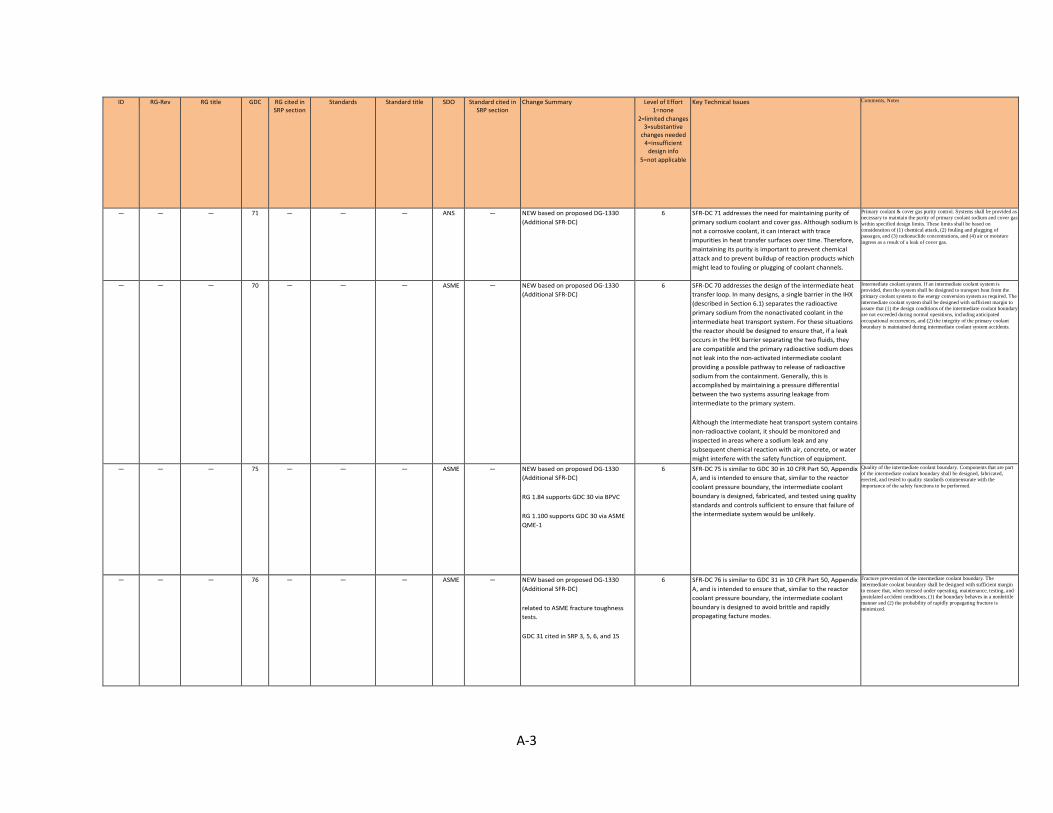
A-3
ID RG-Rev RG title GDC RG cited in SRP section
Standards Standard title SDO Standard cited in SRP section
Change Summary Level of Effort 1=none
2=limited changes 3=substantive
changes needed 4=insufficient
design info 5=not applicable
Key Technical Issues Comments, Notes
— — — 71 — — — ANS — NEW based on proposed DG-1330 (Additional SFR-DC)
6 SFR-DC 71 addresses the need for maintaining purity of primary sodium coolant and cover gas. Although sodium is not a corrosive coolant, it can interact with trace impurities in heat transfer surfaces over time. Therefore, maintaining its purity is important to prevent chemical attack and to prevent buildup of reaction products which might lead to fouling or plugging of coolant channels.
Primary coolant & cover gas purity control. Systems shall be provided as necessary to maintain the purity of primary coolant sodium and cover gas within specified design limits. These limits shall be based on consideration of (1) chemical attack, (2) fouling and plugging of passages, and (3) radionuclide concentrations, and (4) air or moisture ingress as a result of a leak of cover gas.
— — — 70 — — — ASME — NEW based on proposed DG-1330 (Additional SFR-DC)
6 SFR-DC 70 addresses the design of the intermediate heat transfer loop. In many designs, a single barrier in the IHX (described in Section 6.1) separates the radioactive primary sodium from the nonactivated coolant in the intermediate heat transport system. For these situations the reactor should be designed to ensure that, if a leak occurs in the IHX barrier separating the two fluids, they are compatible and the primary radioactive sodium does not leak into the non-activated intermediate coolant providing a possible pathway to release of radioactive sodium from the containment. Generally, this is accomplished by maintaining a pressure differential between the two systems assuring leakage from intermediate to the primary system. Although the intermediate heat transport system contains non-radioactive coolant, it should be monitored and inspected in areas where a sodium leak and any subsequent chemical reaction with air, concrete, or water might interfere with the safety function of equipment.
Intermediate coolant system. If an intermediate coolant system is provided, then the system shall be designed to transport heat from the primary coolant system to the energy conversion system as required. The intermediate coolant system shall be designed with sufficient margin to assure that (1) the design conditions of the intermediate coolant boundary are not exceeded during normal operations, including anticipated occupational occurrences, and (2) the integrity of the primary coolant boundary is maintained during intermediate coolant system accidents.
— — — 75 — — — ASME — NEW based on proposed DG-1330 (Additional SFR-DC) RG 1.84 supports GDC 30 via BPVC RG 1.100 supports GDC 30 via ASME QME-1
6 SFR-DC 75 is similar to GDC 30 in 10 CFR Part 50, Appendix A, and is intended to ensure that, similar to the reactor coolant pressure boundary, the intermediate coolant boundary is designed, fabricated, and tested using quality standards and controls sufficient to ensure that failure of the intermediate system would be unlikely.
Quality of the intermediate coolant boundary. Components that are part of the intermediate coolant boundary shall be designed, fabricated, erected, and tested to quality standards commensurate with the importance of the safety functions to be performed.
— — — 76 — — — ASME — NEW based on proposed DG-1330 (Additional SFR-DC) related to ASME fracture toughness tests. GDC 31 cited in SRP 3, 5, 6, and 15
6 SFR-DC 76 is similar to GDC 31 in 10 CFR Part 50, Appendix A, and is intended to ensure that, similar to the reactor coolant pressure boundary, the intermediate coolant boundary is designed to avoid brittle and rapidly propagating facture modes.
Fracture prevention of the intermediate coolant boundary. The intermediate coolant boundary shall be designed with sufficient margin to ensure that, when stressed under operating, maintenance, testing, and postulated accident conditions, (1) the boundary behaves in a nonbrittle manner and (2) the probability of rapidly propagating fracture is minimized.
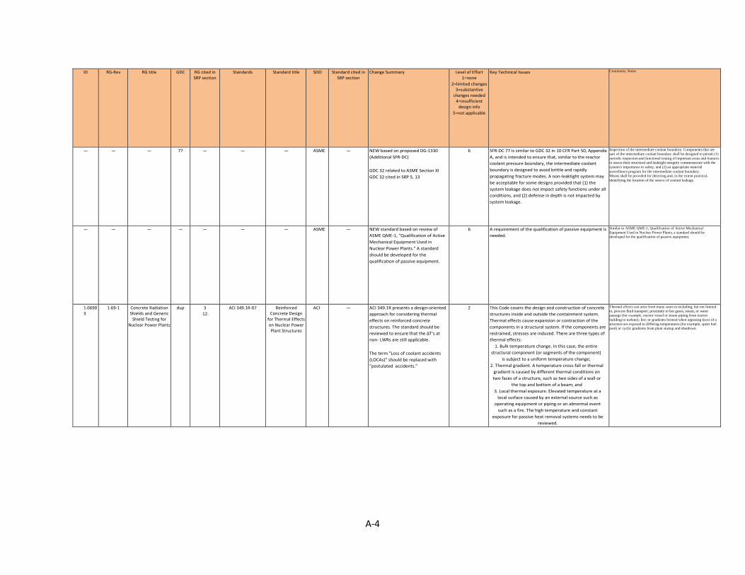
A-4
ID RG-Rev RG title GDC RG cited in SRP section
Standards Standard title SDO Standard cited in SRP section
Change Summary Level of Effort 1=none
2=limited changes 3=substantive
changes needed 4=insufficient
design info 5=not applicable
Key Technical Issues Comments, Notes
— — — 77 — — — ASME — NEW based on proposed DG-1330 (Additional SFR-DC) GDC 32 related to ASME Section XI GDC 32 cited in SRP 5, 13
6 SFR-DC 77 is similar to GDC 32 in 10 CFR Part 50, Appendix A, and is intended to ensure that, similar to the reactor coolant pressure boundary, the intermediate coolant boundary is designed to avoid brittle and rapidly propagating fracture modes. A non-leaktight system may be acceptable for some designs provided that (1) the system leakage does not impact safety functions under all conditions, and (2) defense in depth is not impacted by system leakage.
Inspection of the intermediate coolant boundary. Components that are part of the intermediate coolant boundary shall be designed to permit (1) periodic inspection and functional testing of important areas and features to assess their structural and leaktight integrity commensurate with the system’s importance to safety, and (2) an appropriate material surveillance program for the intermediate coolant boundary. Means shall be provided for detecting and, to the extent practical, identifying the location of the source of coolant leakage.
— — — — — — — ASME — NEW standard based on review of ASME QME-1, "Qualification of Active Mechanical Equipment Used in Nuclear Power Plants." A standard should be developed for the qualification of passive equipment.
6 A requirement of the qualification of passive equipment is needed.
Similar to ASME QME-1, Qualification of Active Mechanical Equipment Used in Nuclear Power Plants, a standard should be developed for the qualification of passive equipment.
1.06903
1.69-1 Concrete Radiation Shields and Generic
Shield Testing for Nuclear Power Plants
dup 3 12
ACI 349.1R-07 Reinforced Concrete Design
for Thermal Effects on Nuclear Power Plant Structures
ACI — ACI 349.1R presents a design-oriented approach for considering thermal effects on reinforced concrete structures. The standard should be reviewed to ensure that the ∆T's at non- LWRs are still applicable. The term "Loss of coolant accidents (LOCAs)" should be replaced with "postulated accidents."
2 This Code covers the design and construction of concrete structures inside and outside the containment system. Thermal effects cause expansion or contraction of the components in a structural system. If the components are restrained, stresses are induced. There are three types of thermal effects:
1. Bulk temperature change. In this case, the entire structural component (or segments of the component)
is subject to a uniform temperature change; 2. Thermal gradient. A temperature cross-fall or thermal
gradient is caused by different thermal conditions on two faces of a structure, such as two sides of a wall or
the top and bottom of a beam; and 3. Local thermal exposure. Elevated temperature at a
local surface caused by an external source such as operating equipment or piping or an abnormal event
such as a fire. The high temperature and constant exposure for passive heat removal systems needs to be
reviewed.
Thermal effects can arise from many sources including, but not limited to, process fluid transport; proximity to hot gases, steam, or water passage (for example, reactor vessel or steam piping from reactor building to turbine); fire; or gradients formed when opposing faces of a structure are exposed to differing temperatures (for example, spent fuel pool) or cyclic gradients from plant startup and shutdown.
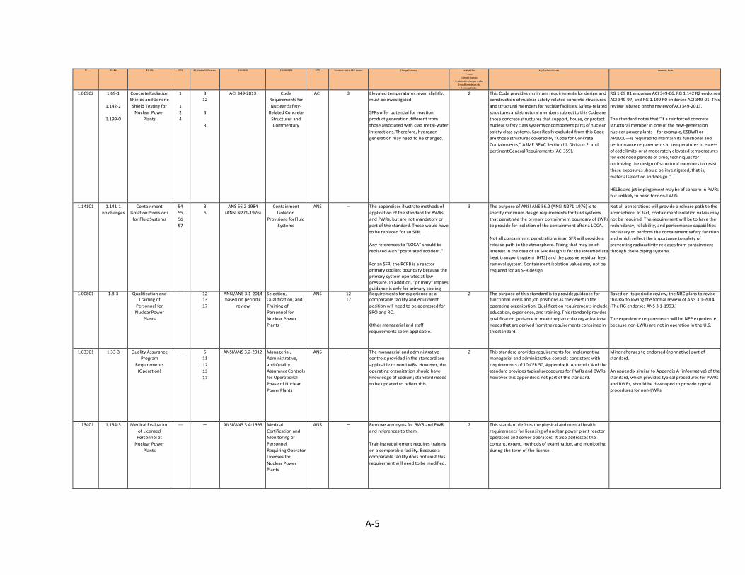
A-5
ID RG-Rev RG title GDC RG cited in SRP section Standards Standard title SDO Standard cited in SRP section Change Summary Level of Effort 1=none
2=limited changes 3=substantive changes needed
4=insufficient design info 5=not applicable
Key Technical Issues Comments, Notes
1.06902 1.69-1
1.142-2
1.199-0
Concrete Radiation Shields and Generic Shield Testing for
Nuclear Power Plants
1
1 2 4
3 12
3
3
ACI 349-2013 Code Requirements for Nuclear Safety-
Related Concrete Structures and Commentary
ACI 3 Elevated temperatures, even slightly, must be investigated. SFRs offer potential for reaction product generation different from those associated with clad metal-water interactions. Therefore, hydrogen generation may need to be changed.
2 This Code provides minimum requirements for design and construction of nuclear safety-related concrete structures and structural members for nuclear facilities. Safety-related structures and structural members subject to this Code are those concrete structures that support, house, or protect nuclear safety class systems or component parts of nuclear safety class systems. Specifically excluded from this Code are those structures covered by “Code for Concrete Containments,” ASME BPVC Section III, Division 2, and pertinent General Requirements (ACI 359).
RG 1.69 R1 endorses ACI 349-06, RG 1.142 R2 endorses ACI 349-97, and RG 1.199 R0 endorses ACI 349-01. This review is based on the review of ACI 349-2013. The standard notes that “If a reinforced concrete structural member in one of the new-generation nuclear power plants—for example, ESBWR or AP1000—is required to maintain its functional and performance requirements at temperatures in excess of code limits, or at moderately elevated temperatures for extended periods of time, techniques for optimizing the design of structural members to resist these exposures should be investigated, that is, material selection and design.” HELBs and jet impingement may be of concern in PWRs but unlikely to be so for non-LWRs.
1.14101 1.141-1 no changes
Containment Isolation Provisions
for Fluid Systems
54 55 56 57
3 6
ANS 56.2-1984 (ANSI N271-1976)
Containment Isolation
Provisions for Fluid Systems
ANS — The appendices illustrate methods of application of the standard for BWRs and PWRs, but are not mandatory or part of the standard. These would have to be replaced for an SFR. Any references to “LOCA” should be replaced with “postulated accident.” For an SFR, the RCPB is a reactor primary coolant boundary because the primary system operates at low- pressure. In addition, "primary" implies guidance is only for primary cooling
3 The purpose of ANSI ANS 56.2 (ANSI N271-1976) is to specify minimum design requirements for fluid systems that penetrate the primary containment boundary of LWRs to provide for isolation of the containment after a LOCA. Not all containment penetrations in an SFR will provide a release path to the atmosphere. Piping that may be of interest in the case of an SFR design is for the intermediate heat transport system (IHTS) and the passive residual heat removal system. Containment isolation valves may not be required for an SFR design.
Not all penetrations will provide a release path to the atmosphere. In fact, containment isolation valves may not be required. The requirement will be to have the redundancy, reliability, and performance capabilities necessary to perform the containment safety function and which reflect the importance to safety of preventing radioactivity releases from containment through these piping systems.
1.00801 1.8-3 Qualification and Training of
Personnel for Nuclear Power
Plants
— 12 13 17
ANSI/ANS 3.1-2014 based on periodic
review
Selection, Qualification, and Training of Personnel for Nuclear Power Plants
ANS 12 17
Requirements for experience at a comparable facility and equivalent position will need to be addressed for SRO and RO. Other managerial and staff requirements seem applicable.
2 The purpose of this standard is to provide guidance for functional levels and job positions as they exist in the operating organization. Qualification requirements include education, experience, and training. This standard provides qualification guidance to meet the particular organizational needs that are derived from the requirements contained in this standard.
Based on its periodic review, the NRC plans to revise this RG following the formal review of ANS 3.1-2014. (The RG endorses ANS 3.1-1993.) The experience requirements will be NPP experience because non-LWRs are not in operation in the U.S.
1.03301 1.33-3 Quality Assurance Program
Requirements (Operation)
— 5 11 12 13 17
ANSI/ANS 3.2-2012 Managerial, Administrative, and Quality Assurance Controls for Operational Phase of Nuclear Power Plants
ANS — The managerial and administrative controls provided in the standard are applicable to non-LWRs. However, the operating organization should have knowledge of Sodium; standard needs to be updated to reflect this.
2 This standard provides requirements for implementing managerial and administrative controls consistent with requirements of 10 CFR 50, Appendix B. Appendix A of the standard provides typical procedures for PWRs and BWRs, however this appendix is not part of the standard.
Minor changes to endorsed (normative) part of standard. An appendix similar to Appendix A (informative) of the standard, which provides typical procedures for PWRs and BWRs, should be developed to provide typical procedures for non-LWRs.
1.13401 1.134-3 Medical Evaluation of Licensed
Personnel at Nuclear Power
Plants
— — ANSI/ANS 3.4-1996 Medical Certification and Monitoring of Personnel Requiring Operator Licenses for Nuclear Power Plants
ANS — Remove acronyms for BWR and PWR and references to them. Training requirement requires training on a comparable facility. Because a comparable facility does not exist this requirement will need to be modified.
2 This standard defines the physical and mental health requirements for licensing of nuclear power plant reactor operators and senior operators. It also addresses the content, extent, methods of examination, and monitoring during the term of the license.

A-6
ID RG-Rev RG title GDC RG cited in SRP section Standards Standard title SDO Standard cited in SRP section Change Summary Level of Effort 1=none
2=limited changes 3=substantive changes needed
4=insufficient design info 5=not applicable
Key Technical Issues Comments, Notes
1.14901 1.149-4 no changes
Nuclear Power Plant Simulation Facilities for Use in Operator Training and License
Examinations
— 13 ANSI/ANS 3.5-2009 Nuclear Power Plant Simulators for Use in Operator Training and Examination
ANS 18 The standard is LWR specific. It needs to be updated for an SFR. For example, loss of coolant accidents (LOCAs) should be replaced with postulated accidents. Emergency electric power may not be applicable.
2 This standard establishes the functional requirements for fu Although the general concept of the standard is applicable to non-LWRs, the standard is LWR specific. Although Appendix B (informative) provides guidelines for the conduct of simulatory operability testing, these tests consist of running the transient events identified in Sec. B.2 for BWRs and B.3 for PWRs. A section should be added for SFRs.
1.13711 1.137-2 Fuel-Oil Systems for Standby Diesel
Generators
dup 3 9
ANSI/ANS 59.51-1997 Fuel Oil Systems for Safety-Related Emergency Diesel
Generators
ANS 9 The purpose of this standard is to define those features of fuel oil systems required to ensure an adequate fuel supply to safety-related emergency diesel generators, and to provide performance and design criteria to ensure sufficient fuel is available for supply to the emergency diesel generators under all plant conditions. Although the criteria may be useful, it is unknown if SFRs will use Class 1E EDGs.
4 The fuel oil system shall be capable of supplying an adequate supply of suitable fuel oil to the emergency diesel generators under all Plant Conditions that are defined ANSI/ANS-51.1-1983 (for PWRs) and ANSI/ANS-52.1-1983 (for BWRs). Both ANS 51.1 and ANS 52.1 have been withdrawn so replacement with an SFR-specific set of plant conditions would not be necessary.
RG 1.137 R1 endorsed ANSI N195-1976. This standard was revised as ANSI/ANS 59.51-1977. RG 1.137 R2 endorses ANSI/ANS 59.51-1977.
1.06906 1.69-1 Concrete Radiation Shields and Generic Shield Testing for
Nuclear Power Plants
dup 3 12
ANSI/ANS 6.3.1-1987 (R2007)
Program for Testing Radiation Shields in Light Water Reactors (LWR)
ANS — A simple change is to remove LWR- specific words. Loss of coolant accidents (LOCAs) should be replaced with postulated accidents. The collection of concrete shielding data presented in this standard is applicable to most practical nuclear power plant shielding designs; however, the data should be reviewed for applicability to non-LWR designs with fast spectrums.
2 This standard describes a test program to be used in evaluating biological radiation shielding in nuclear reactor facilities under normal operating conditions including anticipated operational occurrences. The program encompasses examining and testing to be performed before startup, during startup, and testing subsequent to the startup phase. Post startup tests are required for the shielded components which do not contain sufficient radioactivity during the startup phase to allow valid testing. Post startup shield tests are also required whenever radioactive or potentially radioactive equipment which could affect the adequacy of the installed shielding is introduced into the plant or relocated within the plant, or when previously tested shielding has been modified.
Nuclear heating shall be considered during the determination of the operating temperature and water content of a concrete primary reactor shield and of any other concrete shields that are exposed to an incident energy flux greater than 1010 MeV0cm2 s and that will operate at a temperature of 65°C or greater. concrete shielding designed to protect plant personnel should be tested in accordance with American National Standard “Program for Testing Radiation Shields in Light Water Reactors (LWR),” ANSI-ANS 6.3.1-1987 (R1998).
1.06901 1.69-1 Concrete Radiation Shields and Generic Shield Testing for
Nuclear Power Plants
1 3 12
ANSI/ANS 6.4-2006 Nuclear Analysis and Design of Concrete Radiation Shielding for Nuclear Power Plants
ANS — Types of steel, concrete, and source terms may differ greatly for non-LWRs.
3 This standard contains methods and data needed to calculate the concrete thickness required for radiation shielding in nuclear power plants. Appendix C, which is not a part of the standard, parovides Gamma-ray dose rates from Schedule 80 and Schedule 160 steel pipe, containing airborne or waterborne radioactivity.
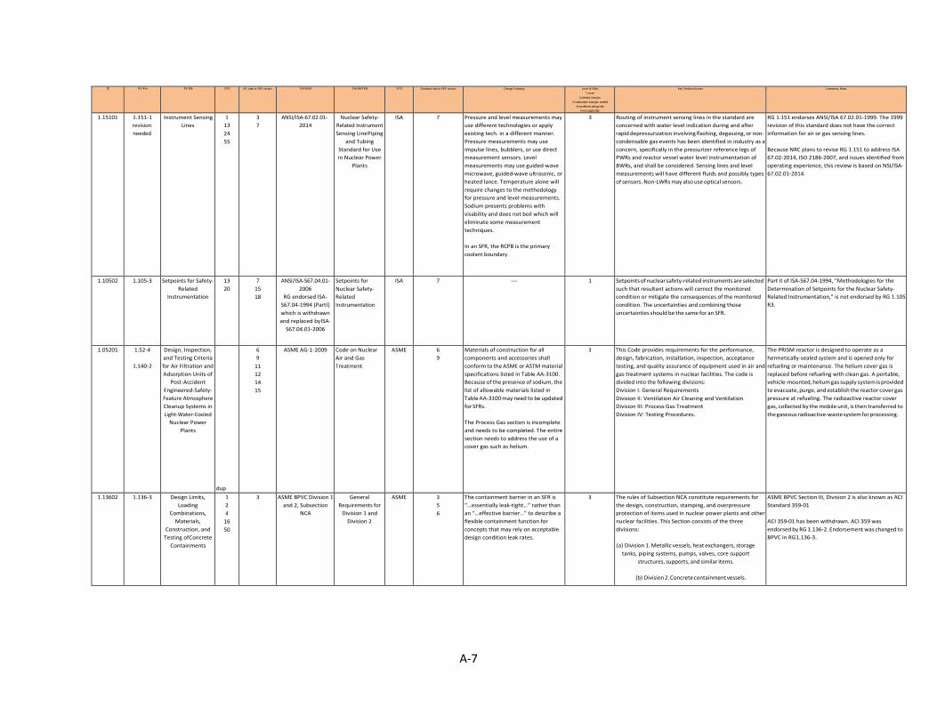
A-7
ID RG-Rev RG title GDC RG cited in SRP section Standards Standard title SDO Standard cited in SRP section Change Summary Level of Effort 1=none
2=limited changes 3=substantive changes needed
4=insufficient design info 5=not applicable
Key Technical Issues Comments, Notes
1.15101 1.151-1 revision needed
Instrument Sensing Lines
1 13 24 55
3 7
ANSI/ISA-67.02.01- 2014
Nuclear Safety- Related Instrument Sensing Line Piping
and Tubing Standard for Use in Nuclear Power
Plants
ISA 7 Pressure and level measurements may use different technologies or apply existing tech. in a different manner. Pressure measurements may use impulse lines, bubblers, or use direct measurement sensors. Level measurements may use guided-wave microwave, guided-wave ultrasonic, or heated lance. Temperature alone will require changes to the methodology for pressure and level measurements. Sodium presents problems with visability and does not boil which will eliminate some measurement techniques. In an SFR, the RCPB is the primary coolant boundary.
3 Routing of instrument sensing lines in the standard are concerned with water level indication during and after rapid depressurization involving flashing, degassing, or non- condensable gas events has been identified in industry as a concern, specifically in the pressurizer reference legs of PWRs and reactor vessel water level instrumentation of BWRs, and shall be considered. Sensing lines and level measurements will have different fluids and possibly types of sensors. Non-LWRs may also use optical sensors.
RG 1.151 endorses ANSI/ISA 67.02.01-1999. The 1999 revision of this standard does not have the correct information for air or gas sensing lines. Because NRC plans to revise RG 1.151 to address ISA 67.02-2014, ISO 2186-2007, and issues identified from operating experience, this review is based on NSI/ISA- 67.02.01-2014.
1.10502 1.105-3 Setpoints for Safety- Related
Instrumentation
13 20
7 15 18
ANSI/ISA-S67.04.01- 2006
RG endorsed ISA- S67.04-1994 (Part I) which is withdrawn and replaced by ISA-
S67.04.01-2006
Setpoints for Nuclear Safety- Related Instrumentation
ISA 7 — 1 Setpoints of nuclear safety-related instruments are selected such that resultant actions will correct the monitored condition or mitigate the consequences of the monitored condition. The uncertainties and combining those uncertainties should be the same for an SFR.
Part II of ISA-S67.04-1994, "Methodologies for the Determination of Setpoints for the Nuclear Safety- Related Instrumentation," is not endorsed by RG 1.105 R3.
1.05201 1.52-4
1.140-2
Design, Inspection, and Testing Criteria for Air Filtration and Adsorption Units of
Post-Accident Engineered-Safety- Feature Atmosphere Cleanup Systems in Light-Water-Cooled
Nuclear Power Plants
dup
6 9
11 12 14 15
ASME AG-1-2009 Code on Nuclear Air and Gas Treatment
ASME 6 9
Materials of construction for all components and accessories shall conform to the ASME or ASTM material specifications listed in Table AA-3100. Because of the presence of sodium, the list of allowable materials listed in Table AA-3100 may need to be updated for SFRs. The Process Gas section is incomplete and needs to be completed. The entire section needs to address the use of a cover gas such as helium.
3 This Code provides requirements for the performance, design, fabrication, installation, inspection, acceptance testing, and quality assurance of equipment used in air and gas treatment systems in nuclear facilities. The code is divided into the following divisions: Division I: General Requirements Division II: Ventilation Air Cleaning and Ventilation Division III: Process Gas Treatment Division IV: Testing Procedures.
The PRISM reactor is designed to operate as a hermetically-sealed system and is opened only for refueling or maintenance. The helium cover gas is replaced before refueling with clean gas. A portable, vehicle-mounted, helium gas supply system is provided to evacuate, purge, and establish the reactor cover gas pressure at refueling. The radioactive reactor cover gas, collected by the mobile unit, is then transferred to the gaseous radioactive-waste system for processing.
1.13602 1.136-3 Design Limits, Loading
Combinations, Materials,
Construction, and Testing of Concrete
Containments
1 2 4
16 50
3 ASME BPVC Division 1 and 2, Subsection
NCA
General Requirements for
Division 1 and Division 2
ASME 3 5 6
The containment barrier in an SFR is “…essentially leak-tight…” rather than an “…effective barrier…” to describe a flexible containment function for concepts that may rely on acceptable design condition leak rates.
3 The rules of Subsection NCA constitute requirements for the design, construction, stamping, and overpressure protection of items used in nuclear power plants and other nuclear facilities. This Section consists of the three divisions: (a) Division 1. Metallic vessels, heat exchangers, storage
tanks, piping systems, pumps, valves, core support structures, supports, and similar items.
(b) Division 2. Concrete containment vessels.
ASME BPVC Section III, Division 2 is also known as ACI Standard 359-01 ACI 359-01 has been withdrawn. ACI 359 was endorsed by RG 1.136-2. Endorsement was changed to BPVC in RG 1.136-3.
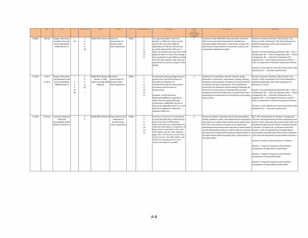
A-8
ID RG-Rev RG title GDC RG cited in SRP section Standards Standard title SDO Standard cited in SRP section Change Summary Level of Effort 1=none
2=limited changes 3=substantive changes needed
4=insufficient design info 5=not applicable
Key Technical Issues Comments, Notes
1.08401 1.84-36 Design, Fabrication, and Materials Code Case Acceptability,
ASME Section III
1 30
3 4 5 6
10
ASME BPVC Section III Rules for Construction of Nuclear Power Plant Components
ASME 3 4 5 6 9
10 15 17
The approved tables 1 and 2 are specific to LWRS only. There may be some of the cases that might be applicable to a SFR but they are only currently approved for LWR use. It there are existing code cases that a SFR applicant wants to use for their design they would have to get ASME to review them for that purpose. Code cases are specifically focused on an aspect of the design.
3 Provisions of the ASME BPV Code have been used since 1971 as one part of the framework to establish the necessary design, fabrication, construction, testing, and performance requirements for structures, systems, and components important to safety.
Section III consists of Division 1 (N), Division 2 (C), Division 3 (W), and Division 5 (H). Each Subsection is published separately, with some exceptions for Divisions 2, 3, and 5. Division 1 has the following subsections: NB — Class 1 Components, NC — Class 2 Components, ND — Class 3 Components, NE — Class MC Components, NF — Supports, NG — Core Support Structures, and NH — Class 1 Components in Elevated Temperature Service. Division 2 is the Code for Concrete Containments with Subsection CC — Concrete Containments.
1.10701 1.107-2
1.136-3
Design, Fabrication, and Materials Code Case Acceptability,
ASME Section III
1
1 2 4
16 50
3 4 5 6
10
√
ASME BPVC Section III Division 2, 2001
edition through 2003 Addenda
Rules for Construction of Nuclear Power Plant Components
ASME 3 4 5 6 9
10 15 17
Containments having a Design Pressure greater than 5 psi (35 kPa) that are classified as Subsection CC containments shall be constructed in accordance with the rules of Subsection CC. However, an SFR will have a significantly different containment rather than the typical LWR-type containment. ASME BPVC Section III may not be applicable and if it is, it will have to be updated to reflect this significant difference.
3 Subsection CC establishes rules for material, design, fabrication, construction, examination, testing, marking, stamping, and preparation of reports for prestressed and reinforced concrete containments. The containments covered by this Subsection shall include the following: (a) structural concrete pressure resisting shells and shell components (b) shell metallic liners (c) penetration liners extending the containment liner through the surrounding shell concrete.
Section III consists of Division 1 (N), Division 2 (C), Division 3 (W), and Division 5 (H). Each Subsection is published separately, with some exceptions for Divisions 2, 3, and 5. Division 1 has the following subsections: NB — Class 1 Components, NC — Class 2 Components, ND — Class 3 Components, NE — Class MC Components, NF — Supports, NG — Core Support Structures, and NH — Class 1 Components in Elevated Temperature Service. Division 2 is the Code for Concrete Containments with Subsection CC — Concrete Containments.
1.14701 1.147-16 Inservice Inspection Code Case
Acceptability, ASME Section XI, Division 1
— 3 5
ASME BPVC Section XI Rules for Inservice Inspection of
Nuclear Power Plant Components
ASME 3 5 6 9
10 13 14
The rules in Division 3 are intended to be generally applicable to either the loop type or pool type of LMR primary coolan‐t syste‐m. For the requirements for inspection and testing of components of liquid metal cooled plants, refer to the 2001 Edition with the 2003 Addenda, pages 482–716. However, this revision will be inactive. The 2001 Edition will need to be incorporated into a new version and updated as needed.
3 Section XI, Division 3 provides rules for the examination, testing, inspection, repair, and replacement of components and systems in a liquid-metal-cooled nuclear power plant. The rules in this Division of Section XI are based upon anticipated service environments peculiar to systems which contain liquid metals (sodium or sodium alloys) as coolants and upon the comprehensive protection against failure of the liquid-metal coolant boundary that is characteristic of this type of plant.
RG 1.147 is ISI of Section XI, Division 1 components. The rules and requirements for those components and systems of this plant type that contain other fluids are provided by references to Articles or portions thereof in Division 1 of Section XI, on the basis that these Division 1 rules are appropriate and applicable to Liquid-Metal-Cooled Nuclear Power Plants; otherwise such rules and requirements are provided in Division 3. Section XI consists of three Divisions, as follows: Division 1 = Rules for Inspection and Testing of Components of Light-Water-Cooled Plants Division 2 = Rules for Inspection and Testing of Components of Gas-Cooled Plants Division 3 = Rules for Inspection and Testing of Components of Liquid-Metal-Cooled Plants
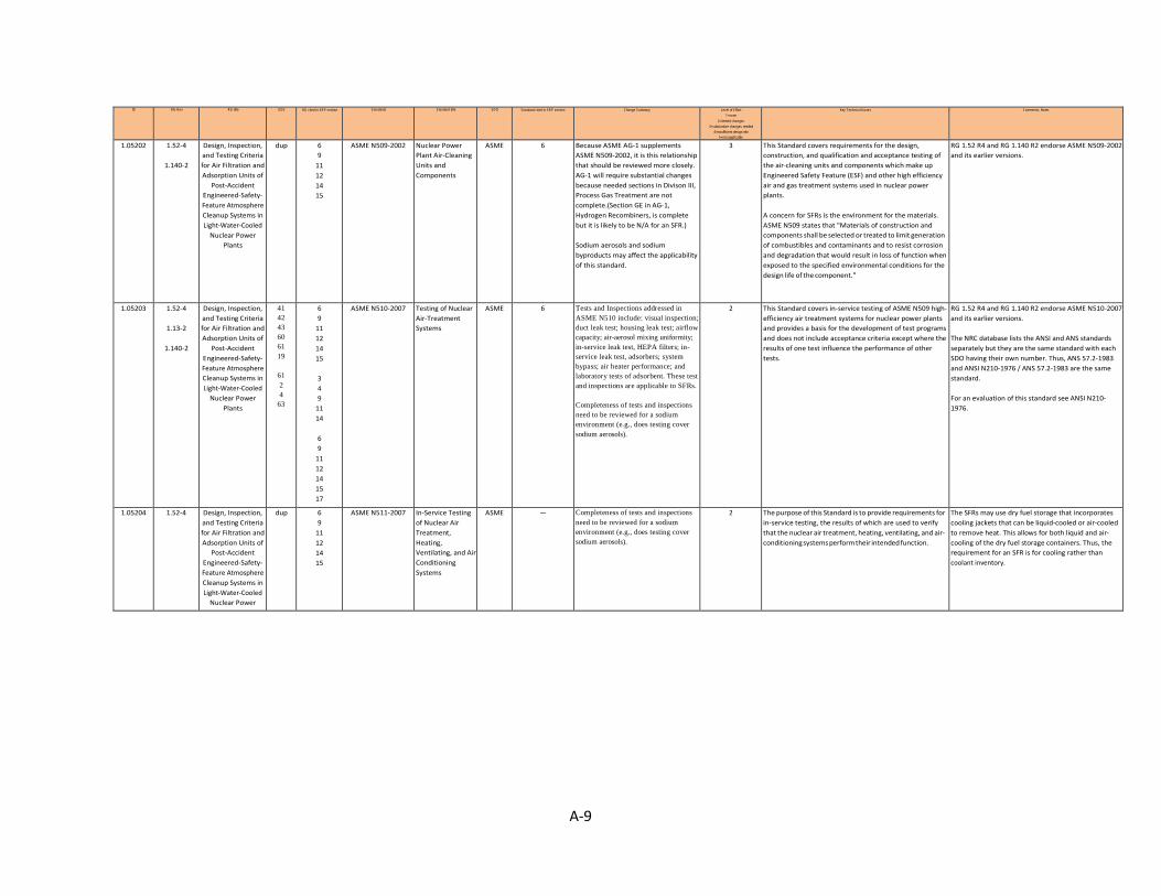
A-9
ID RG-Rev RG title GDC RG cited in SRP section Standards Standard title SDO Standard cited in SRP section Change Summary Level of Effort 1=none
2=limited changes 3=substantive changes needed
4=insufficient design info 5=not applicable
Key Technical Issues Comments, Notes
1.05202 1.52-4
1.140-2
Design, Inspection, and Testing Criteria for Air Filtration and Adsorption Units of
Post-Accident Engineered-Safety- Feature Atmosphere Cleanup Systems in Light-Water-Cooled
Nuclear Power Plants
dup 6 9
11 12 14 15
ASME N509-2002 Nuclear Power Plant Air-Cleaning Units and Components
ASME 6 Because ASME AG-1 supplements ASME N509-2002, it is this relationship that should be reviewed more closely. AG-1 will require substantial changes because needed sections in Divison III, Process Gas Treatment are not complete.(Section GE in AG-1, Hydrogen Recombiners, is complete but it is likely to be N/A for an SFR.) Sodium aerosols and sodium byproducts may affect the applicability of this standard.
3 This Standard covers requirements for the design, construction, and qualification and acceptance testing of the air-cleaning units and components which make up Engineered Safety Feature (ESF) and other high efficiency air and gas treatment systems used in nuclear power plants. A concern for SFRs is the environment for the materials. ASME N509 states that "Materials of construction and components shall be selected or treated to limit generation of combustibles and contaminants and to resist corrosion and degradation that would result in loss of function when exposed to the specified environmental conditions for the design life of the component."
RG 1.52 R4 and RG 1.140 R2 endorse ASME N509-2002 and its earlier versions.
1.05203 1.52-4
1.13-2
1.140-2
Design, Inspection, and Testing Criteria for Air Filtration and Adsorption Units of
Post-Accident Engineered-Safety- Feature Atmosphere Cleanup Systems in Light-Water-Cooled
Nuclear Power Plants
41 42 43 60 61 19
61 2 4
63
6 9
11 12 14 15
3 4 9
11 14
6 9
11 12 14 15 17
ASME N510-2007 Testing of Nuclear Air-Treatment Systems
ASME 6 Tests and Inspections addressed in ASME N510 include: visual inspection; duct leak test; housing leak test; airflow capacity; air-aerosol mixing uniformity; in-service leak test, HEPA filters; in- service leak test, adsorbers; system bypass; air heater performance; and laboratory tests of adsorbent. These test and inspections are applicable to SFRs. Completeness of tests and inspections need to be reviewed for a sodium environment (e.g., does testing cover sodium aerosols).
2 This Standard covers in-service testing of ASME N509 high- efficiency air treatment systems for nuclear power plants and provides a basis for the development of test programs and does not include acceptance criteria except where the results of one test influence the performance of other tests.
RG 1.52 R4 and RG 1.140 R2 endorse ASME N510-2007 and its earlier versions. The NRC database lists the ANSI and ANS standards separately but they are the same standard with each SDO having their own number. Thus, ANS 57.2-1983 and ANSI N210-1976 / ANS 57.2-1983 are the same standard. For an evaluation of this standard see ANSI N210- 1976.
1.05204 1.52-4 Design, Inspection, and Testing Criteria for Air Filtration and Adsorption Units of
Post-Accident Engineered-Safety- Feature Atmosphere Cleanup Systems in Light-Water-Cooled
Nuclear Power
dup 6 9
11 12 14 15
ASME N511-2007 In-Service Testing of Nuclear Air Treatment, Heating, Ventilating, and Air Conditioning Systems
ASME — Completeness of tests and inspections need to be reviewed for a sodium environment (e.g., does testing cover sodium aerosols).
2 The purpose of this Standard is to provide requirements for in-service testing, the results of which are used to verify that the nuclear air treatment, heating, ventilating, and air- conditioning systems perform their intended function.
The SFRs may use dry fuel storage that incorporates cooling jackets that can be liquid-cooled or air-cooled to remove heat. This allows for both liquid and air- cooling of the dry fuel storage containers. Thus, the requirement for an SFR is for cooling rather than coolant inventory.

A-10
ID RG-Rev RG title GDC RG cited in SRP section Standards Standard title SDO Standard cited in SRP section Change Summary Level of Effort 1=none
2=limited changes 3=substantive changes needed
4=insufficient design info 5=not applicable
Key Technical Issues Comments, Notes
1.02804 1.28-4 revision TBD
1.8-3
Quality Assurance Program Criteria
(Design and Construction)
1
—
2 5 7
17
√
ASME NQA-1-2008 Quality Assurance Requirements for Nuclear Facility Applications
ASME 4 5 7
17
— 1 NQA-1 is a multipart Standard that provides includes requirements and nonmandatory guidance to establish and implement a QA program for any nuclear facility application. Part I contains QA program requirements for the siting, design, construction, operation, and decommissioning of nuclear facilities. Part II contains QA requirements for the planning and conducting of the fabrication, construction, modification, repair, maintenance, and testing of systems, components, or activities for nuclear facilities. Part III contains nonmandatory guidance. Part IV contains NQA position papers and other quality program information.
RG 1.28 R4 endorses ASME NQA-1-2008 and ASME NQA-1a-2009. The RG endorses both separately so both were kept as individual standards. Should we have one as a duplicate? RG 1.8 endorses ASME NQA-1-1983 and RG 1.28 R4 endorses ASME NQA-1-2008. The -2008 version is used for this review. The NRC staff performed a review and identified that differences exist between the previously endorsed guidance (NQA-1-2008 and NQA-1a-2009 addenda) and the most recently issued guidance (NQA-1b-2011, NQA-1-2012 and NQA-1-2015). Additional time and resources are required to understand the impact of these changes. The NRC staff continues to endorse the previous guidance and is not aware of any issues that would preclude its use.
1.02805 1.28-4 revision TBD
Quality Assurance Program Criteria
(Design and Construction)
dup 2 5 7
17
ASME NQA-1a-2009 (Addenda to ASME
NQA-1-2008)
Quality Assurance Requirements for Nuclear Facility Applications
ASME 7 — 1 NQA-1 is a multipart Standard that provides includes requirements and nonmandatory guidance to establish and implement a QA program for any nuclear facility application. Part I contains QA program requirements for the siting, design, construction, operation, and decommissioning of nuclear facilities. Part II contains QA requirements for the planning and conducting of the fabrication, construction, modification, repair, maintenance, and testing of systems, components, or activities for nuclear facilities. Part III contains nonmandatory guidance. Part IV contains NQA position papers and other quality program information.
The NRC staff performed a review and identified that differences exist between the previously endorsed guidance (NQA-1-2008 and NQA-1a-2009 addenda) and the most recently issued guidance (NQA-1b-2011, NQA-1-2012 and NQA-1-2015). Additional time and resources are required to understand the impact of these changes. The NRC staff continues to endorse the previous guidance and is not aware of any issues that would preclude its use.
1.10004 1.100-3 no revision
Seismic Qualification of
Electric and Mechanical
Equipment for Nuclear Power
Plants
1 2
14 30 37 40 43 46 54
3 5 7
ASME QME-1-2007 Qualification of Active Mechanical Equipment Used in Nuclear Power Plants
ASME 3 Some of the requirements and guidance provided in this standard are not be applicable to the non-LWRs because the qualification requirements and guidelines are for active components that must function to ensure safe operation, safe shutdown, or opeation during design basis events. Other components, such as dynamic restraints are applicable. The standard should be updated to reflect only those applicable portions. Cooling water systems should be changed to structural and equipment cooling systems.
3 This Standard provides the requirements and guidelines for the qualification of active mechanical equipment whose function is required to ensure the safe operation or safe shutdown of a nuclear facility. In addition to requirements and guidelines put forth in this Standard, the active mechanical equipment shall comply with the requirements of the applicable design and construction codes and standards. Advanced Light Water Reactor (ALWR) First-of-a- Kind Engineering Project on Equipment Seismic Qualification, Advanced Reactor Corporation (ARC), April 1995 and NUREG/CR-6464, “An Evaluation of Methodology for Seismic Qualification of Equipment, Cable Trays, and Ducts in ALWR Plants by Use of Experience Data.” USNRC, 1997 are cited as non-mandatory references for active mechanical equipment.
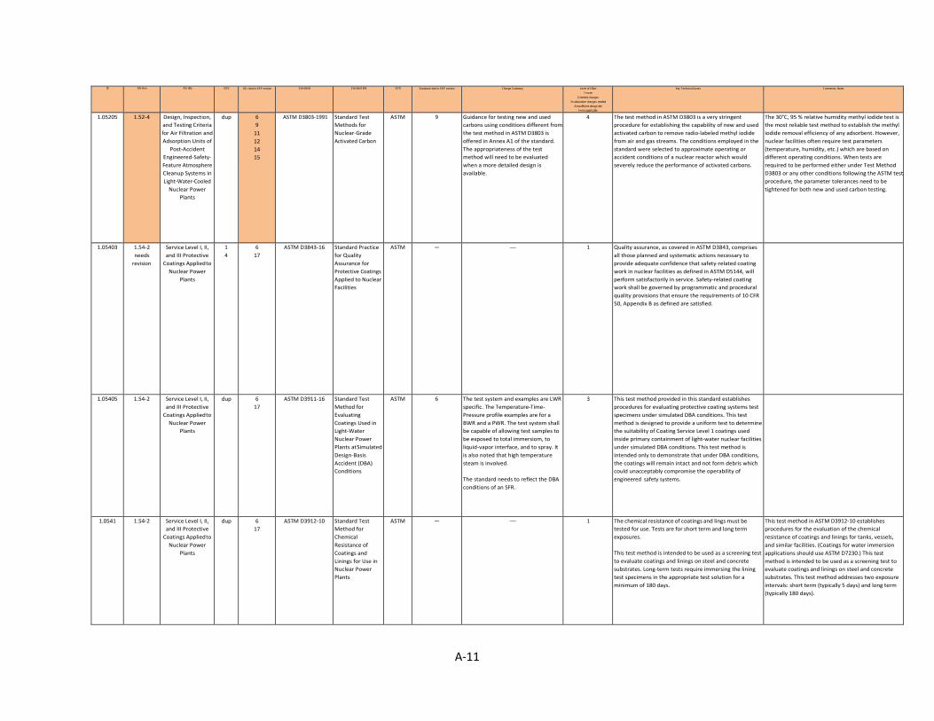
A-11
ID RG-Rev RG title GDC RG cited in SRP section Standards Standard title SDO Standard cited in SRP section Change Summary Level of Effort 1=none
2=limited changes 3=substantive changes needed
4=insufficient design info 5=not applicable
Key Technical Issues Comments, Notes
1.05205 1.52-4 Design, Inspection, and Testing Criteria for Air Filtration and Adsorption Units of
Post-Accident Engineered-Safety- Feature Atmosphere Cleanup Systems in Light-Water-Cooled
Nuclear Power Plants
dup 6 9
11 12 14 15
ASTM D3803-1991 Standard Test Methods for Nuclear-Grade Activated Carbon
ASTM 9 Guidance for testing new and used carbons using conditions different from the test method in ASTM D3803 is offered in Annex A1 of the standard. The appropriateness of the test method will need to be evaluated when a more detailed design is available.
4 The test method in ASTM D3803 is a very stringent procedure for establishing the capability of new and used activated carbon to remove radio-labeled methyl iodide from air and gas streams. The conditions employed in the standard were selected to approximate operating or accident conditions of a nuclear reactor which would severely reduce the performance of activated carbons.
The 30°C, 95 % relative humidity methyl iodide test is the most reliable test method to establish the methyl iodide removal efficiency of any adsorbent. However, nuclear facilities often require test parameters (temperature, humidity, etc.) which are based on different operating conditions. When tests are required to be performed either under Test Method D3803 or any other conditions following the ASTM test procedure, the parameter tolerances need to be tightened for both new and used carbon testing.
1.05403 1.54-2 needs
revision
Service Level I, II, and III Protective
Coatings Applied to Nuclear Power
Plants
1 4
6 17
ASTM D3843-16 Standard Practice for Quality Assurance for Protective Coatings Applied to Nuclear Facilities
ASTM — — 1 Quality assurance, as covered in ASTM D3843, comprises all those planned and systematic actions necessary to provide adequate confidence that safety-related coating work in nuclear facilities as defined in ASTM D5144, will perform satisfactorily in service. Safety-related coating work shall be governed by programmatic and procedural quality provisions that ensure the requirements of 10 CFR 50, Appendix B as defined are satisfied.
1.05405 1.54-2 Service Level I, II, and III Protective
Coatings Applied to Nuclear Power
Plants
dup 6 17
ASTM D3911-16 Standard Test Method for Evaluating Coatings Used in Light-Water Nuclear Power Plants at Simulated Design-Basis Accident (DBA) Conditions
ASTM 6 The test system and examples are LWR specific. The Temperature-Time- Pressure profile examples are for a BWR and a PWR. The test system shall be capable of allowing test samples to be exposed to total immersiom, to liquid-vapor interface, and to spray. It is also noted that high temperature steam is involved. The standard needs to reflect the DBA conditions of an SFR.
3 This test method provided in this standard establishes procedures for evaluating protective coating systems test specimens under simulated DBA conditions. This test method is designed to provide a uniform test to determine the suitability of Coating Service Level 1 coatings used inside primary containment of light-water nuclear facilities under simulated DBA conditions. This test method is intended only to demonstrate that under DBA conditions, the coatings will remain intact and not form debris which could unacceptably compromise the operability of engineered safety systems.
1.0541 1.54-2 Service Level I, II, and III Protective
Coatings Applied to Nuclear Power
Plants
dup 6 17
ASTM D3912-10 Standard Test Method for Chemical Resistance of Coatings and Linings for Use in Nuclear Power Plants
ASTM — — 1 The chemical resistance of coatings and lings must be tested for use. Tests are for short term and long term exposures. This test method is intended to be used as a screening test to evaluate coatings and linings on steel and concrete substrates. Long-term tests require immersing the lining test specimens in the appropriate test solution for a minimum of 180 days.
This test method in ASTM D3912-10 establishes procedures for the evaluation of the chemical resistance of coatings and linings for tanks, vessels, and similar facilities. (Coatings for water immersion applications should use ASTM D7230.) This test method is intended to be used as a screening test to evaluate coatings and linings on steel and concrete substrates. This test method addresses two exposure intervals: short term (typically 5 days) and long term (typically 180 days).
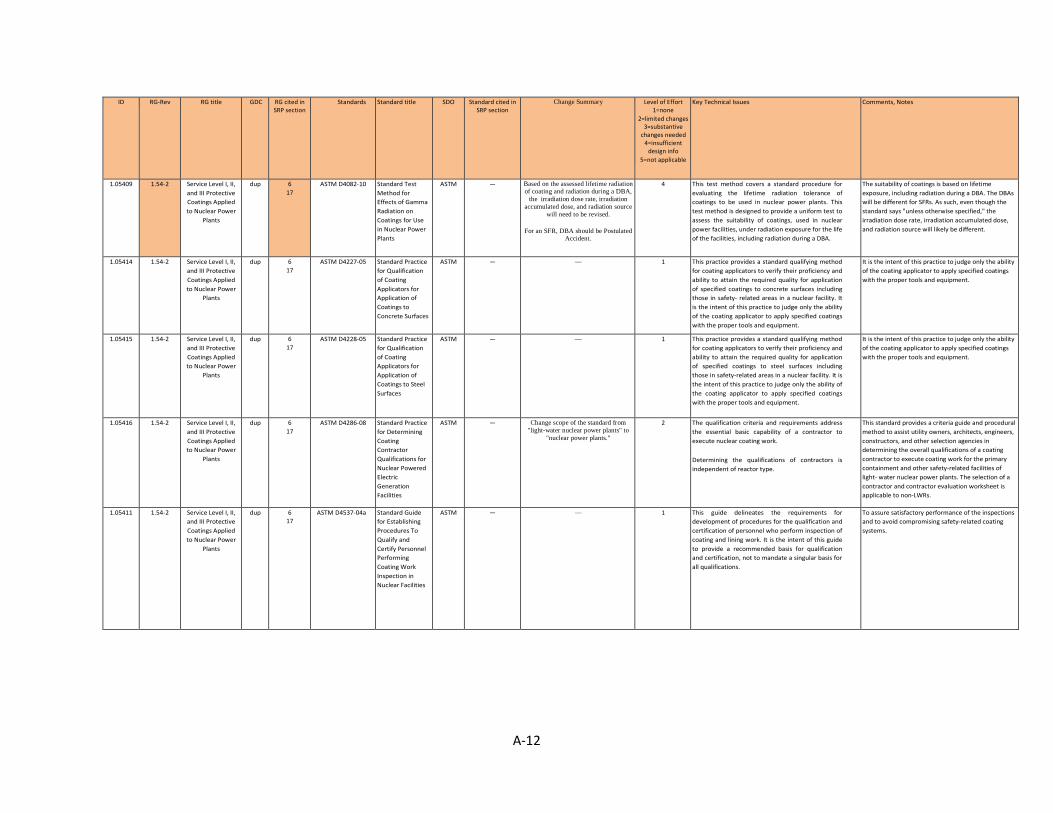
A-12
ID RG-Rev RG title GDC RG cited in SRP section
Standards Standard title SDO Standard cited in SRP section
Change Summary Level of Effort 1=none
2=limited changes 3=substantive
changes needed 4=insufficient
design info 5=not applicable
Key Technical Issues Comments, Notes
1.05409 1.54-2 Service Level I, II, and III Protective Coatings Applied to Nuclear Power
Plants
dup 6 17
ASTM D4082-10 Standard Test Method for Effects of Gamma Radiation on Coatings for Use in Nuclear Power Plants
ASTM — Based on the assessed lifetime radiation of coating and radiation during a DBA,
the irradiation dose rate, irradiation accumulated dose, and radiation source
will need to be revised.
For an SFR, DBA should be Postulated Accident.
4 This test method covers a standard procedure for evaluating the lifetime radiation tolerance of coatings to be used in nuclear power plants. This test method is designed to provide a uniform test to assess the suitability of coatings, used in nuclear power facilities, under radiation exposure for the life of the facilities, including radiation during a DBA.
The suitability of coatings is based on lifetime exposure, including radiation during a DBA. The DBAs will be different for SFRs. As such, even though the standard says "unless otherwise specified," the irradiation dose rate, irradiation accumulated dose, and radiation source will likely be different.
1.05414 1.54-2 Service Level I, II, and III Protective Coatings Applied to Nuclear Power
Plants
dup 6 17
ASTM D4227-05 Standard Practice for Qualification of Coating Applicators for Application of Coatings to Concrete Surfaces
ASTM — — 1 This practice provides a standard qualifying method for coating applicators to verify their proficiency and ability to attain the required quality for application of specified coatings to concrete surfaces including those in safety- related areas in a nuclear facility. It is the intent of this practice to judge only the ability of the coating applicator to apply specified coatings with the proper tools and equipment.
It is the intent of this practice to judge only the ability of the coating applicator to apply specified coatings with the proper tools and equipment.
1.05415 1.54-2 Service Level I, II, and III Protective Coatings Applied to Nuclear Power
Plants
dup 6 17
ASTM D4228-05 Standard Practice for Qualification of Coating Applicators for Application of Coatings to Steel Surfaces
ASTM — — 1 This practice provides a standard qualifying method for coating applicators to verify their proficiency and ability to attain the required quality for application of specified coatings to steel surfaces including those in safety-related areas in a nuclear facility. It is the intent of this practice to judge only the ability of the coating applicator to apply specified coatings with the proper tools and equipment.
It is the intent of this practice to judge only the ability of the coating applicator to apply specified coatings with the proper tools and equipment.
1.05416 1.54-2 Service Level I, II, and III Protective Coatings Applied to Nuclear Power
Plants
dup 6 17
ASTM D4286-08 Standard Practice for Determining Coating Contractor Qualifications for Nuclear Powered Electric Generation Facilities
ASTM — Change scope of the standard from "light-water nuclear power plants" to
"nuclear power plants."
2 The qualification criteria and requirements address the essential basic capability of a contractor to execute nuclear coating work. Determining the qualifications of contractors is independent of reactor type.
This standard provides a criteria guide and procedural method to assist utility owners, architects, engineers, constructors, and other selection agencies in determining the overall qualifications of a coating contractor to execute coating work for the primary containment and other safety-related facilities of light- water nuclear power plants. The selection of a contractor and contractor evaluation worksheet is applicable to non-LWRs.
1.05411 1.54-2 Service Level I, II, and III Protective Coatings Applied to Nuclear Power
Plants
dup 6 17
ASTM D4537-04a Standard Guide for Establishing Procedures To Qualify and Certify Personnel Performing Coating Work Inspection in Nuclear Facilities
ASTM — — 1 This guide delineates the requirements for development of procedures for the qualification and certification of personnel who perform inspection of coating and lining work. It is the intent of this guide to provide a recommended basis for qualification and certification, not to mandate a singular basis for all qualifications.
To assure satisfactory performance of the inspections and to avoid compromising safety-related coating systems.
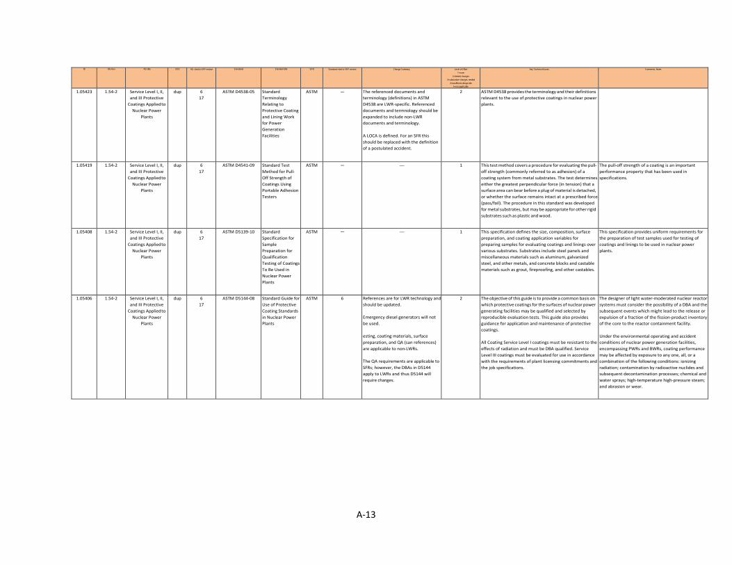
A-13
ID RG-Rev RG title GDC RG cited in SRP section Standards Standard title SDO Standard cited in SRP section Change Summary Level of Effort 1=none
2=limited changes 3=substantive changes needed
4=insufficient design info 5=not applicable
Key Technical Issues Comments, Notes
1.05423 1.54-2 Service Level I, II, and III Protective
Coatings Applied to Nuclear Power
Plants
dup 6 17
ASTM D4538-05 Standard Terminology Relating to Protective Coating and Lining Work for Power Generation Facilities
ASTM — The referenced documents and terminology (definitions) in ASTM D4538 are LWR-specific. Referenced documents and termnology should be expanded to include non-LWR documents and terminology. A LOCA is defined. For an SFR this should be replaced with the definition of a postulated accident.
2 ASTM D4538 provides the terminology and their definitions relevant to the use of protective coatings in nuclear power plants.
1.05419 1.54-2 Service Level I, II, and III Protective
Coatings Applied to Nuclear Power
Plants
dup 6 17
ASTM D4541-09 Standard Test Method for Pull- Off Strength of Coatings Using Portable Adhesion Testers
ASTM — — 1 This test method covers a procedure for evaluating the pull- off strength (commonly referred to as adhesion) of a coating system from metal substrates. The test determines either the greatest perpendicular force (in tension) that a surface area can bear before a plug of material is detached, or whether the surface remains intact at a prescribed force (pass/fail). The procedure in this standard was developed for metal substrates, but may be appropriate for other rigid substrates such as plastic and wood.
The pull-off strength of a coating is an important performance property that has been used in specifications.
1.05408 1.54-2 Service Level I, II, and III Protective
Coatings Applied to Nuclear Power
Plants
dup 6 17
ASTM D5139-10 Standard Specification for Sample Preparation for Qualification Testing of Coatings To Be Used in Nuclear Power Plants
ASTM — — 1 This specification defines the size, composition, surface preparation, and coating application variables for preparing samples for evaluating coatings and linings over various substrates. Substrates include steel panels and miscellaneous materials such as aluminum, galvanized steel, and other metals, and concrete blocks and castable materials such as grout, fireproofing, and other castables.
This specification provides uniform requirements for the preparation of test samples used for testing of coatings and linings to be used in nuclear power plants.
1.05406 1.54-2 Service Level I, II, and III Protective
Coatings Applied to Nuclear Power
Plants
dup 6 17
ASTM D5144-08 Standard Guide for Use of Protective Coating Standards in Nuclear Power Plants
ASTM 6 References are for LWR technology and should be updated. Emergency diesel generators will not be used. esting, coating materials, surface preparation, and QA (san references) are applicable to non-LWRs. The QA requirements are applicable to SFRs; however, the DBAs in D5144 apply to LWRs and thus D5144 will require changes.
2 The objective of this guide is to provide a common basis on which protective coatings for the surfaces of nuclear power generating facilities may be qualified and selected by reproducible evaluation tests. This guide also provides guidance for application and maintenance of protective coatings. All Coating Service Level I coatings must be resistant to the effects of radiation and must be DBA qualified. Service Level III coatings must be evaluated for use in accordance with the requirements of plant licensing commitments and the job specifications.
The designer of light water-moderated nuclear reactor systems must consider the possibility of a DBA and the subsequent events which might lead to the release or expulsion of a fraction of the fission-product inventory of the core to the reactor containment facility. Under the environmental operating and accident conditions of nuclear power generation facilities, encompassing PWRs and BWRs, coating performance may be affected by exposure to any one, all, or a combination of the following conditions: ionizing radiation; contamination by radioactive nuclides and subsequent decontamination processes; chemical and water sprays; high-temperature high-pressure steam; and abrasion or wear.
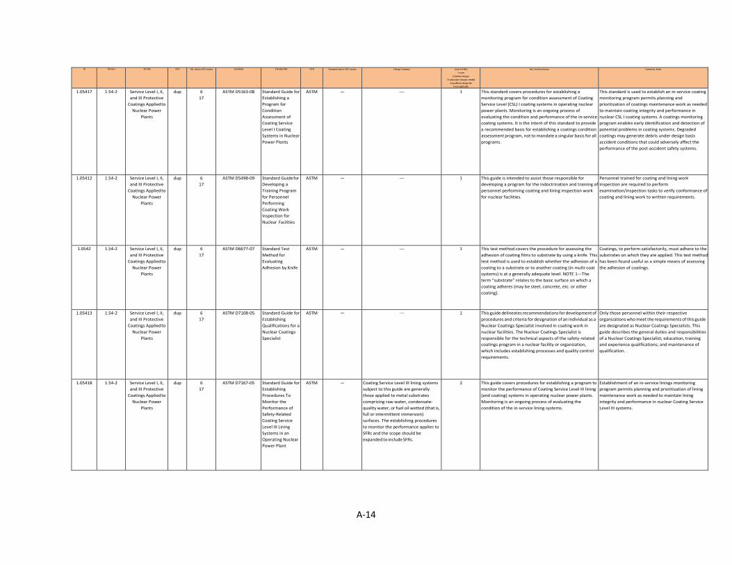
A-14
ID RG-Rev RG title GDC RG cited in SRP section Standards Standard title SDO Standard cited in SRP section Change Summary Level of Effort 1=none
2=limited changes 3=substantive changes needed
4=insufficient design info 5=not applicable
Key Technical Issues Comments, Notes
1.05417 1.54-2 Service Level I, II, and III Protective
Coatings Applied to Nuclear Power
Plants
dup 6 17
ASTM D5163-08 Standard Guide for Establishing a Program for Condition Assessment of Coating Service Level I Coating Systems in Nuclear Power Plants
ASTM — — 1 This standard covers procedures for establishing a monitoring program for condition assessment of Coating Service Level (CSL) I coating systems in operating nuclear power plants. Monitoring is an ongoing process of evaluating the condition and performance of the in-service coating systems. It is the intent of this standard to provide a recommended basis for establishing a coatings condition assessment program, not to mandate a singular basis for all programs.
This standard is used to establish an in-service coating monitoring program permits planning and prioritization of coatings maintenance work as needed to maintain coating integrity and performance in nuclear CSL I coating systems. A coatings monitoring program enables early identification and detection of potential problems in coating systems. Degraded coatings may generate debris under design basis accident conditions that could adversely affect the performance of the post-accident safety systems.
1.05412 1.54-2 Service Level I, II, and III Protective
Coatings Applied to Nuclear Power
Plants
dup 6 17
ASTM D5498-09 Standard Guide for Developing a Training Program for Personnel Performing Coating Work Inspection for Nuclear Facilities
ASTM — — 1 This guide is intended to assist those responsible for developing a program for the indoctrination and training of personnel performing coating and lining inspection work for nuclear facilities.
Personnel trained for coating and lining work inspection are required to perform examination/inspection tasks to verify conformance of coating and lining work to written requirements.
1.0542 1.54-2 Service Level I, II, and III Protective
Coatings Applied to Nuclear Power
Plants
dup 6 17
ASTM D6677-07 Standard Test Method for Evaluating Adhesion by Knife
ASTM — — 1 This test method covers the procedure for assessing the adhesion of coating films to substrate by using a knife. This test method is used to establish whether the adhesion of a coating to a substrate or to another coating (in multi-coat systems) is at a generally adequate level. NOTE 1—The term “substrate” relates to the basic surface on which a coating adheres (may be steel, concrete, etc. or other coating).
Coatings, to perform satisfactorily, must adhere to the substrates on which they are applied. This test method has been found useful as a simple means of assessing the adhesion of coatings.
1.05413 1.54-2 Service Level I, II, and III Protective
Coatings Applied to Nuclear Power
Plants
dup 6 17
ASTM D7108-05 Standard Guide for Establishing Qualifications for a Nuclear Coatings Specialist
ASTM — — 1 This guide delineates recommendations for development of procedures and criteria for designation of an individual as a Nuclear Coatings Specialist involved in coating work in nuclear facilities. The Nuclear Coatings Specialist is responsible for the technical aspects of the safety-related coatings program in a nuclear facility or organization, which includes establishing processes and quality control requirements.
Only those personnel within their respective organizations who meet the requirements of this guide are designated as Nuclear Coatings Specialists. This guide describes the general duties and responsibilities of a Nuclear Coatings Specialist; education, training and experience qualifications; and maintenance of qualification.
1.05418 1.54-2 Service Level I, II, and III Protective
Coatings Applied to Nuclear Power
Plants
dup 6 17
ASTM D7167-05 Standard Guide for Establishing Procedures To Monitor the Performance of Safety-Related Coating Service Level III Lining Systems in an Operating Nuclear Power Plant
ASTM — Coating Service Level III lining systems subject to this guide are generally those applied to metal substrates comprising raw water, condensate- quality water, or fuel oil wetted (that is, full or intermittent immersion) surfaces. The establishing procedures to monitor the performance applies to SFRs and the scope should be expanded to include SFRs.
2 This guide covers procedures for establishing a program to monitor the performance of Coating Service Level III lining (and coating) systems in operating nuclear power plants. Monitoring is an ongoing process of evaluating the condition of the in-service lining systems.
Establishment of an in-service linings monitoring program permits planning and prioritization of lining maintenance work as needed to maintain lining integrity and performance in nuclear Coating Service Level III systems.
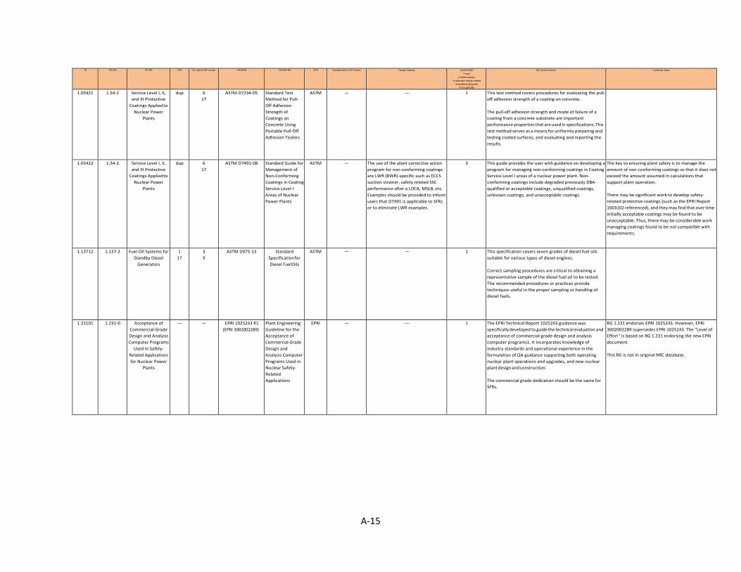
A-15
ID RG-Rev RG title GDC RG cited in SRP section Standards Standard title SDO Standard cited in SRP section Change Summary Level of Effort 1=none
2=limited changes 3=substantive changes needed
4=insufficient design info 5=not applicable
Key Technical Issues Comments, Notes
1.05421 1.54-2 Service Level I, II, and III Protective
Coatings Applied to Nuclear Power
Plants
dup 6 17
ASTM D7234-05 Standard Test Method for Pull- Off Adhesion Strength of Coatings on Concrete Using Portable Pull-Off Adhesion Testers
ASTM — — 1 This test method covers procedures for evaluating the pull- off adhesion strength of a coating on concrete. The pull-off adhesion strength and mode of failure of a coating from a concrete substrate are important performance properties that are used in specifications. This test method serves as a means for uniformly preparing and testing coated surfaces, and evaluating and reporting the results.
1.05422 1.54-2 Service Level I, II, and III Protective
Coatings Applied to Nuclear Power
Plants
dup 6 17
ASTM D7491-08 Standard Guide for Management of Non-Conforming Coatings in Coating Service Level I Areas of Nuclear Power Plants
ASTM — The use of the plant corrective action program for non-conforming coatings are LWR (BWR)-specific such as ECCS suction strainer, safety related SSC performance after a LOCA, MSLB, etc. Examples should be provided to inform users that D7491 is applicable to SFRs or to eliminate LWR examples.
3 This guide provides the user with guidance on developing a program for managing non-conforming coatings in Coating Service Level I areas of a nuclear power plant. Non- conforming coatings include degraded previously DBA- qualified or acceptable coatings, unqualified coatings, unknown coatings, and unacceptable coatings.
The key to ensuring plant safety is to manage the amount of non-conforming coatings so that it does not exceed the amount assumed in calculations that support plant operation. There may be significant work to develop safety- related protective coatings (such as the EPRI Report 1003102 referenced), and they may find that over time initially acceptable coatings may be found to be unacceptable. Thus, there may be considerable work managing coatings found to be not compatible with requirements.
1.13712 1.137-2 Fuel-Oil Systems for Standby Diesel
Generators
1 17
3 9
ASTM D975-13 Standard Specification for Diesel Fuel Oils
ASTM — — 1 This specification covers seven grades of diesel fuel oils suitable for various types of diesel engines. Correct sampling procedures are critical to obtaining a representative sample of the diesel fuel oil to be tested. The recommended procedures or practices provide techniques useful in the proper sampling or handling of diesel fuels.
1.23101 1.231-0 Acceptance of Commercial-Grade Design and Analysis Computer Programs
Used In Safety- Related Applications for Nuclear Power
Plants
— — EPRI 1025243 R1 (EPRI 3002002289)
Plant Engineering: Guideline for the Acceptance of Commercial-Grade Design and Analysis Computer Programs Used in Nuclear Safety- Related Applications
EPRI — — 1 The EPRI Technical Report 1025243 guidance was specifically developed to guide the technical evaluation and acceptance of commercial-grade design and analysis computer programs1. It incorporates knowledge of industry standards and operational experience in the formulation of QA guidance supporting both operating nuclear plant operations and upgrades, and new nuclear plant design and construction. The commercial grade dedication should be the same for SFRs.
RG 1.231 endorses EPRI 1025243. However, EPRI 3002002289 supersedes EPRI 1025243. The "Level of Effort" is based on RG 1.231 endorsing the new EPRI document. This RG is not in original NRC database.
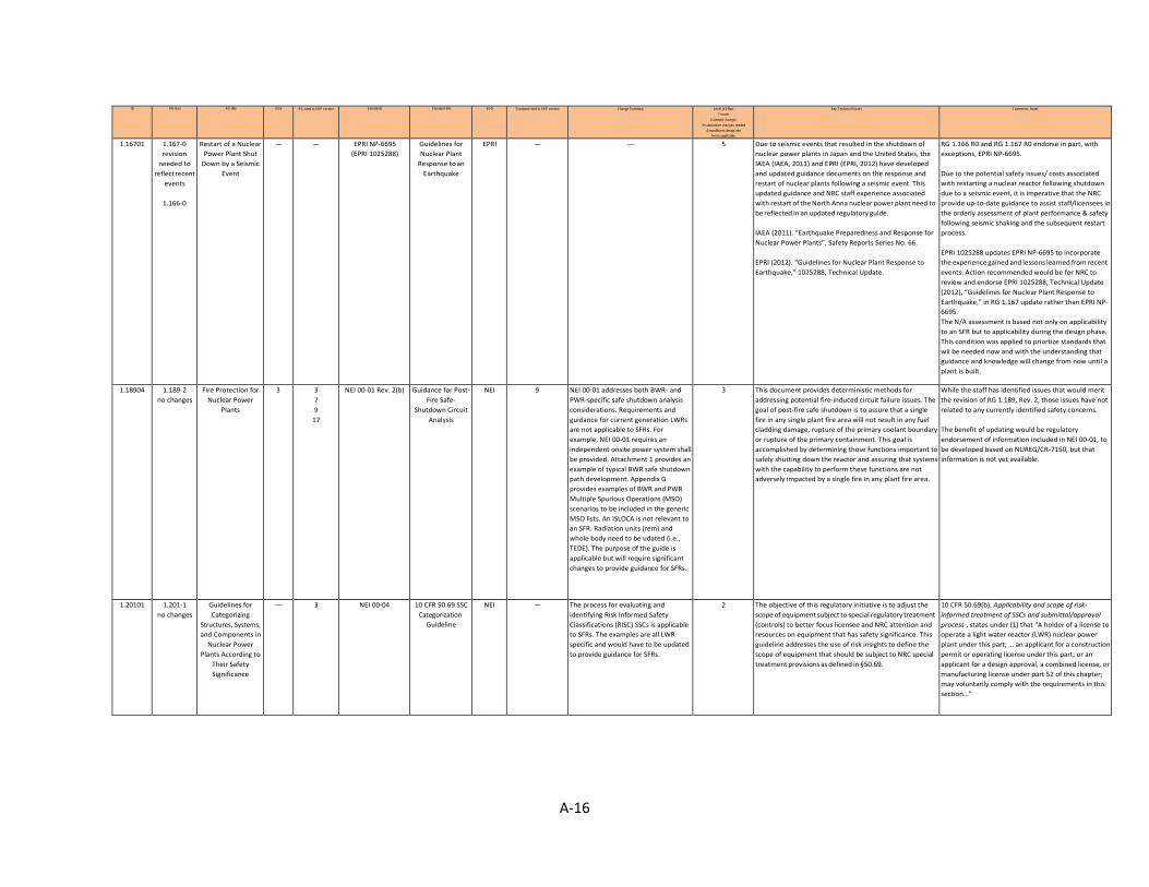
A-16
ID RG-Rev RG title GDC RG cited in SRP section Standards Standard title SDO Standard cited in SRP section Change Summary Level of Effort 1=none
2=limited changes 3=substantive changes needed
4=insufficient design info 5=not applicable
Key Technical Issues Comments, Notes
1.16701 1.167-0 revision
needed to reflect recent
events
1.166-0
Restart of a Nuclear Power Plant Shut
Down by a Seismic Event
— — EPRI NP-6695 (EPRI 1025288)
Guidelines for Nuclear Plant
Response to an Earthquake
EPRI — — 5 Due to seismic events that resulted in the shutdown of nuclear power plants in Japan and the United States, the IAEA (IAEA, 2011) and EPRI (EPRI, 2012) have developed and updated guidance documents on the response and restart of nuclear plants following a seismic event. This updated guidance and NRC staff experience associated with restart of the North Anna nuclear power plant need to be reflected in an updated regulatory guide. IAEA (2011). “Earthquake Preparedness and Response for Nuclear Power Plants”, Safety Reports Series No. 66. EPRI (2012). “Guidelines for Nuclear Plant Response to Earthquake,” 1025288, Technical Update.
RG 1.166 R0 and RG 1.167 R0 endorse in part, with exceptions, EPRI NP-6695. Due to the potential safety issues/ costs associated with restarting a nuclear reactor following shutdown due to a seismic event, it is imperative that the NRC provide up-to-date guidance to assist staff/licensees in the orderly assessment of plant performance & safety following seismic shaking and the subsequent restart process. EPRI 1025288 updates EPRI NP-6695 to incorporate the experience gained and lessons learned from recent events. Action recommended would be for NRC to review and endorse EPRI 1025288, Technical Update (2012), “Guidelines for Nuclear Plant Response to Earthquake,” in RG 1.167 update rather than EPRI NP- 6695. The N/A assessment is based not only on applicability to an SFR but to applicability during the design phase. This condition was applied to priortize standards that wil be needed now and with the understanding that guidance and knowledge will change from now until a plant is built.
1.18904 1.189-2 no changes
Fire Protection for Nuclear Power
Plants
3 3 7 9
17
NEI 00-01 Rev. 2(b) Guidance for Post- Fire Safe-
Shutdown Circuit Analysis
NEI 9 NEI 00-01 addresses both BWR- and PWR-specific safe shutdown analysis considerations. Requirements and guidance for current generation LWRs are not applicable to SFRs. For example, NEI 00-01 requires an independent onsite power system shall be provided. Attachment 1 provides an example of typical BWR safe shutdown path development. Appendix G provides examples of BWR and PWR Multiple Spurious Operations (MSO) scenarios to be included in the generic MSO lists. An ISLOCA is not relevant to an SFR. Radiation units (rem) and whole body need to be udated (i.e., TEDE). The purpose of the guide is applicable but will require significant changes to provide guidance for SFRs.
3 This document provides deterministic methods for addressing potential fire-induced circuit failure issues. The goal of post-fire safe shutdown is to assure that a single fire in any single plant fire area will not result in any fuel cladding damage, rupture of the primary coolant boundary or rupture of the primary containment. This goal is accomplished by determining those functions important to safely shutting down the reactor and assuring that systems with the capability to perform these functions are not adversely impacted by a single fire in any plant fire area.
While the staff has identified issues that would merit the revision of RG 1.189, Rev. 2, those issues have not related to any currently identified safety concerns. The benefit of updating would be regulatory endorsement of information included in NEI 00-01, to be developed based on NUREG/CR-7150, but that information is not yet available.
1.20101 1.201-1 no changes
Guidelines for Categorizing
Structures, Systems, and Components in
Nuclear Power Plants According to
Their Safety Significance
— 3 NEI 00-04 10 CFR 50.69 SSC Categorization
Guideline
NEI — The process for evaluating and identifying Risk Informed Safety Classifications (RISC) SSCs is applicable to SFRs. The examples are all LWR specific and would have to be updated to provide guidance for SFRs.
2 The objective of this regulatory initiative is to adjust the scope of equipment subject to special regulatory treatment (controls) to better focus licensee and NRC attention and resources on equipment that has safety significance. This guideline addresses the use of risk insights to define the scope of equipment that should be subject to NRC special treatment provisions as defined in §50.69.
10 CFR 50.69(b), Applicability and scope of risk- informed treatment of SSCs and submittal/approval process , states under (1) that “A holder of a license to operate a light water reactor (LWR) nuclear power plant under this part; … an applicant for a construction permit or operating license under this part; or an applicant for a design approval, a combined license, or manufacturing license under part 52 of this chapter; may voluntarily comply with the requirements in this section…”
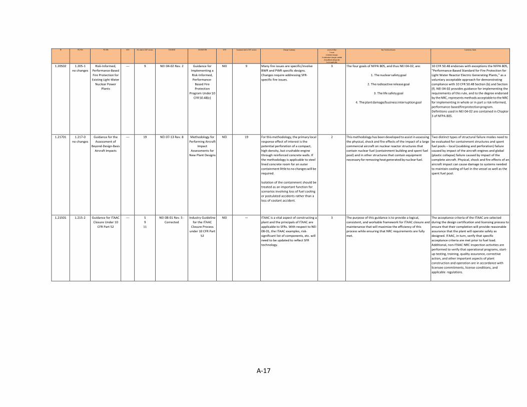
A-17
ID RG-Rev RG title GDC RG cited in SRP section Standards Standard title SDO Standard cited in SRP section Change Summary Level of Effort 1=none
2=limited changes 3=substantive changes needed
4=insufficient design info 5=not applicable
Key Technical Issues Comments, Notes
1.20502 1.205-1 no changes
Risk-Informed, Performance-Based Fire Protection for Existing Light-Water
Nuclear Power Plants
— 9 NEI 04-02 Rev. 2 Guidance for Implementing a Risk-Informed, Performance-
Based Fire Protection
Program Under 10 CFR 50.48(c)
NEI 9 Many fire issues are specific/involve BWR and PWR specific designs. Changes require addressing SFR- specific fire issues.
3 The four goals of NFPA 805, and thus NEI 04-02, are:
1. The nuclear safety goal
2. The radioactive release goal
3. The life safety goal
4. The plant damage/business interruption goal
10 CFR 50.48 endorses with exceptions the NFPA 805, "Performance-Based Standard for Fire Protection for Light Water Reactor Electric Generating Plants," as a voluntary acceptable approach for demonstrating compliance with 10 CFR 50.48 Section (b) and Section (f). NEI 04-02 provides guidance for implementing the requirements of this rule, and to the degree endorsed by the NRC, represents methods acceptable to the NRC for implementing in whole or in part a risk-informed, performance-based fire protection program. Definitions used in NEI 04-02 are contained in Chapter 3 of NFPA 805.
1.21701 1.217-0 no changes
Guidance for the Assessment of
Beyond-Design-Basis Aircraft Impacts
— 19 NEI 07-13 Rev. 8 Methodology for Performing Aircraft
Impact Assessments for
New Plant Designs
NEI 19 For this methodology, the primary local response effect of interest is the potential perforation of a compact, high density, but crushable engine through reinforced concrete walls. If the methodology is applicable to steel lined concrete room for an outer containment little to no changes will be required. Isolation of the containment should be treated as an important function for scenarios involving loss of fuel cooling or postulated accidents rather than a loss of coolant accident.
2 This methodology has been developed to assist in assessing the physical, shock and fire effects of the impact of a large commercial aircraft on nuclear reactor structures that contain nuclear fuel (containment building and spent fuel pool) and in other structures that contain equipment necessary for removing heat generated by nuclear fuel.
Two distinct types of structural failure modes need to be evaluated for containment structures and spent fuel pools – local (scabbing and perforation) failure caused by impact of the aircraft engines and global (plastic collapse) failure caused by impact of the complete aircraft. Physical, shock and fire effects of an aircraft impact can cause damage to systems needed to maintain cooling of fuel in the vessel as well as the spent fuel pool.
1.21501 1.215-2 Guidance for ITAAC Closure Under 10
CFR Part 52
— 5 9
11
NEI 08-01 Rev. 5 - Corrected
Industry Guideline for the ITAAC
Closure Process under 10 CFR Part
52
NEI — ITAAC is a vital aspect of constructing a plant and the principals of ITAAC are applicable to SFRs. With respect to NEI 08-01, the ITAAC examples, risk- significant list of components, etc. will need to be updated to reflect SFR technology.
3 The purpose of this guidance is to provide a logical, consistent, and workable framework for ITAAC closure and maintenance that will maximize the efficiency of this process while ensuring that NRC requirements are fully met.
The acceptance criteria of the ITAAC are selected during the design certification and licensing process to ensure that their completion will provide reasonable assurance that the plant will operate safely as designed. ITAAC, in turn, verify that specific acceptance criteria are met prior to fuel load. Additional, non-ITAAC NRC inspection activities are performed to verify that operational programs, start- up testing, training, quality assurance, corrective action, and other important aspects of plant construction and operation are in accordance with licensee commitments, license conditions, and applicable regulations.
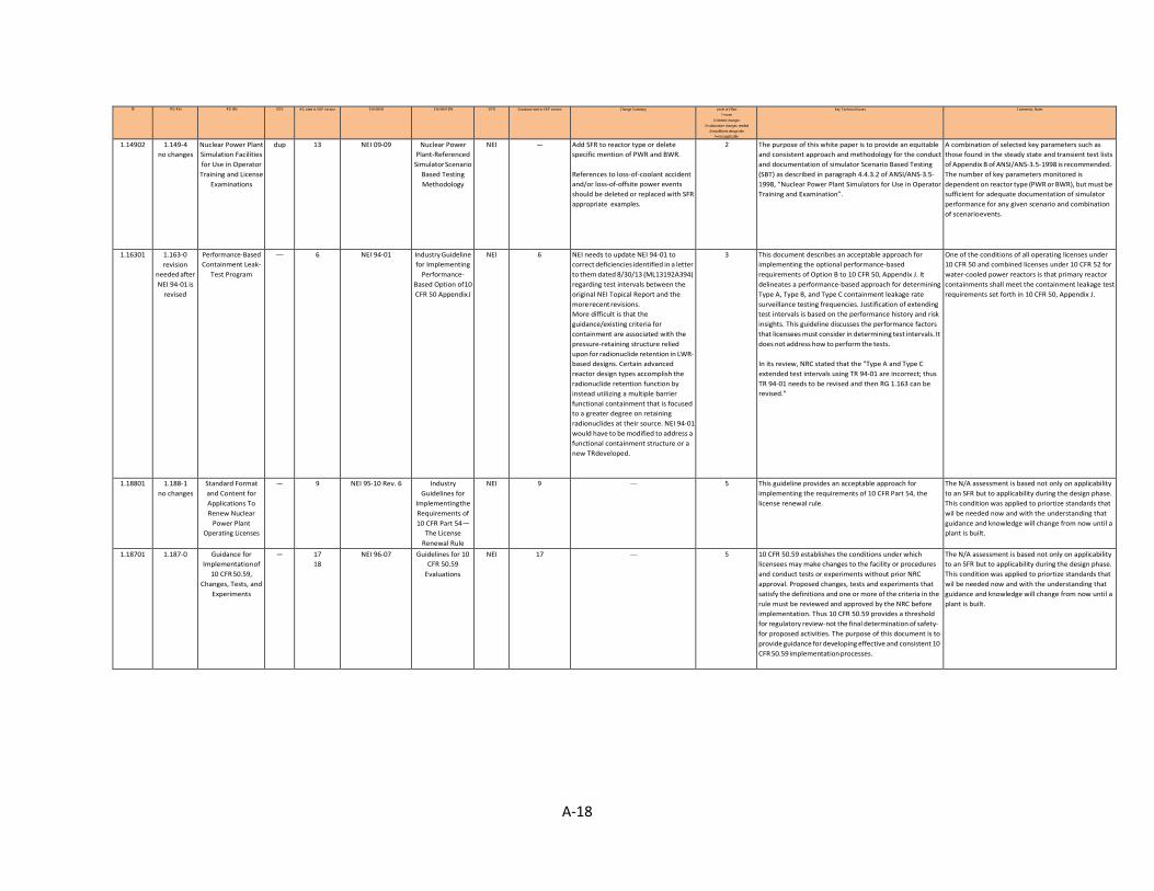
A-18
ID RG-Rev RG title GDC RG cited in SRP section Standards Standard title SDO Standard cited in SRP section Change Summary Level of Effort 1=none
2=limited changes 3=substantive changes needed
4=insufficient design info 5=not applicable
Key Technical Issues Comments, Notes
1.14902 1.149-4 no changes
Nuclear Power Plant Simulation Facilities for Use in Operator Training and License
Examinations
dup 13 NEI 09-09 Nuclear Power Plant-Referenced
Simulator Scenario Based Testing Methodology
NEI — Add SFR to reactor type or delete specific mention of PWR and BWR. References to loss-of-coolant accident and/or loss-of-offsite power events should be deleted or replaced with SFR appropriate examples.
2 The purpose of this white paper is to provide an equitable and consistent approach and methodology for the conduct and documentation of simulator Scenario Based Testing (SBT) as described in paragraph 4.4.3.2 of ANSI/ANS-3.5- 1998, “Nuclear Power Plant Simulators for Use in Operator Training and Examination”.
A combination of selected key parameters such as those found in the steady state and transient test lists of Appendix B of ANSI/ANS-3.5-1998 is recommended. The number of key parameters monitored is dependent on reactor type (PWR or BWR), but must be sufficient for adequate documentation of simulator performance for any given scenario and combination of scenario events.
1.16301 1.163-0 revision
needed after NEI 94-01 is
revised
Performance-Based Containment Leak-
Test Program
— 6 NEI 94-01 Industry Guideline for Implementing
Performance- Based Option of 10 CFR 50 Appendix J
NEI 6 NEI needs to update NEI 94-01 to correct deficiencies identified in a letter to them dated 8/30/13 (ML13192A394) regarding test intervals between the original NEI Topical Report and the more recent revisions. More difficult is that the guidance/existing criteria for containment are associated with the pressure-retaining structure relied upon for radionuclide retention in LWR- based designs. Certain advanced reactor design types accomplish the radionuclide retention function by instead utilizing a multiple barrier functional containment that is focused to a greater degree on retaining radionuclides at their source. NEI 94-01 would have to be modified to address a functional containment structure or a new TR developed.
3 This document describes an acceptable approach for implementing the optional performance-based requirements of Option B to 10 CFR 50, Appendix J. It delineates a performance-based approach for determining Type A, Type B, and Type C containment leakage rate surveillance testing frequencies. Justification of extending test intervals is based on the performance history and risk insights. This guideline discusses the performance factors that licensees must consider in determining test intervals. It does not address how to perform the tests. In its review, NRC stated that the "Type A and Type C extended test intervals using TR 94-01 are incorrect; thus TR 94-01 needs to be revised and then RG 1.163 can be revised."
One of the conditions of all operating licenses under 10 CFR 50 and combined licenses under 10 CFR 52 for water-cooled power reactors is that primary reactor containments shall meet the containment leakage test requirements set forth in 10 CFR 50, Appendix J.
1.18801 1.188-1 no changes
Standard Format and Content for Applications To Renew Nuclear
Power Plant Operating Licenses
— 9 NEI 95-10 Rev. 6 Industry Guidelines for
Implementing the Requirements of 10 CFR Part 54 —
The License Renewal Rule
NEI 9 — 5 This guideline provides an acceptable approach for implementing the requirements of 10 CFR Part 54, the license renewal rule.
The N/A assessment is based not only on applicability to an SFR but to applicability during the design phase. This condition was applied to priortize standards that wil be needed now and with the understanding that guidance and knowledge will change from now until a plant is built.
1.18701 1.187-0 Guidance for Implementation of
10 CFR 50.59, Changes, Tests, and
Experiments
— 17 18
NEI 96-07 Guidelines for 10 CFR 50.59
Evaluations
NEI 17 — 5 10 CFR 50.59 establishes the conditions under which licensees may make changes to the facility or procedures and conduct tests or experiments without prior NRC approval. Proposed changes, tests and experiments that satisfy the definitions and one or more of the criteria in the rule must be reviewed and approved by the NRC before implementation. Thus 10 CFR 50.59 provides a threshold for regulatory review-not the final determination of safety- for proposed activities. The purpose of this document is to provide guidance for developing effective and consistent 10 CFR 50.59 implementation processes.
The N/A assessment is based not only on applicability to an SFR but to applicability during the design phase. This condition was applied to priortize standards that wil be needed now and with the understanding that guidance and knowledge will change from now until a plant is built.
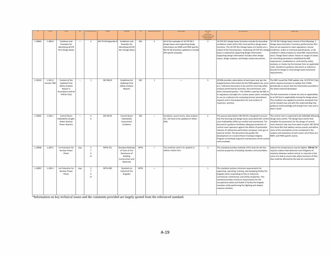
A-19
ID RG-Rev RG title GDC RG cited in SRP section Standards Standard title SDO Standard cited in SRP section Change Summary Level of Effort 1=none
2=limited changes 3=substantive changes needed
4=insufficient design info 5=not applicable
Key Technical Issues Comments, Notes
1.18601 1.186-0 Guidance and Examples for
Identifying 10 CFR 50.2 Design Bases
— 3 NEI 97-04 Appendix B Guidelines and Examples for
Identifying 10 CFR 50.2 Design Bases
NEI 3 All of the examples of 10 CFR 50.2 design bases and supporting design information are BWR and PWR specific. NEI 97-04 should be updated to include SFR-specific examples.
3 10 CFR 50.2 design bases functions include the bounding conditions under which SSCs must perform design bases functions. The 10 CFR 50.2 design bases of a facility are a subset of the licensing basis. Underlying 10 CFR 50.2 design bases is substantial supporting design information. Supporting design information includes other design inputs, design analyses, and design output documents.
10 CFR 50.2 design bases consist of the following: 1. Design bases functions: Functions performed by SSCs that are (a) required to meet regulations, license conditions, orders or technical specifications, or (b) credited in safety analyses to meet NRC requirements and 2. Design bases values: Values or ranges of values of controlling parameters established by NRC requirement, established or confirmed by safety analyses, or chosen by the licensee from an applicable code, standard or guidance document as reference bounds for design to meet design bases functional requirements.
1.18101 1.181-0 revision TBD
Content of the Updated Final Safety Analysis
Report in Accordance with 10
CFR 50.71(e)
— 1 NEI 98-03 Guidelines for Updating Final Safety Analysis
Reports
NEI 1 — 5 UFSARs provide a description of each plant and, per the Supplementary Information for the FSAR update rule, serve as a “reference document to be used for recurring safety analyses performed by licensees, the Commission, and other interested parties.” The UFSAR is used by the NRC in its regulatory oversight of a nuclear power plant, including its use as a reference for evaluating license amendment requests and in the preparation for and conduct of inspection activities.
The NRC issued the FSAR update rule, 10 CFR 50.71(e), which requires licensees to update their FSARs periodically to assure that the information provided is the latest material developed. The N/A assessment is based not only on applicability to an SFR but to applicability during the design phase. This condition was applied to priortize standards that wil be needed now and with the understanding that guidance and knowledge will change from now until a plant is built.
1.19601 1.196-1 Control Room Habitability at Light-
Water Nuclear Power Reactors
— 4 6
NEI 99-03 Control Room Habitability Assessment
Guidance
NEI — Accidents, source terms, dose analysis, etc. will have to be updated to reflect SFRs.
3 The process described in NEI 99-03 is designed to ensure that the licensing and design bases associated with control room habitability (CRH) are verified and maintained. The document's guidance facilitates adequate protection of control room operators against the effects of postulated releases of radioactive particulates and gases, toxic gas or external smoke. The document also guides the development of a Control Room Envelope Integrity Program to facilitate long-term maintenance of the control room envelope.
The control room is expected to be habitable following design basis events. The design basis events that establish the parameters for the design of control room features may vary from plant to plant. NEI 99-03 lists those RGs that address various events and define some of the assumptions to be considered in the analysis and evaluation of each event; all of these are BWR- and PWR-specific events.
1.18906 1.189-2 ire Protection for Nuclear Power
Plants
dup 3 7 9
17
NFPA 251 Standard Methods of Tests of Fire Resistance of
Building Construction and
Materials
NFPA — Test methods need to be updated to address sodium fires.
3 This standard provides methods of fire tests for the fire- resistive properties of building members and assemblies.
Sodium fire temperatures may be highter. SFR-DC 73 requires sodium leak detection and mitigation of reactions between sodium and air or concrete in the event of a leak to assure that safety functions of SSCs that could be affected by the leak are maintained.
1.18907 1.189-2 ire Protection for Nuclear Power
Plants
dup 3 7 9
17
NFPA 600 Standard on Industrial Fire
Brigades
NFPA — — 1 This standard contains minimum requirements for organizing, operating, training, and equipping facility fire brigades when responding to fires in industrial, commercial, institutional, and similar properties. This standard provides minimum requirements for the occupational safety and health of facility fire brigade members while performing fire fighting and related response activities.
*Information on key technical issues and the comments provided are largely quoted from the referenced standard.


B-1
APPENDIX B. IEEE STANDARDS ENDORSED BY REGULATORY GUIDES
ID RG-REV
RG Title GDC RG Cited in
SRP Section
Standards Standard Title SDO Standard Cited in
SRP Section
Change Summary
Level of Effort 1=none
2=limited changes 3=substantive
changes needed 4=insufficient design info
5=not applicable 6=new design-
specific requirement
Key Technical Issues*
Comments and Notes*
1.03201 1.32-3 Criteria for Safety-Related Electric Power Systems for Nuclear Power Plants
17 18
8 IEEE 308-2001 Criteria for Class 1E Power Systems for Nuclear Power Generating Stations
IEEE 8 14
— 1 This standard applies to the Class 1E portions of the following systems and equipment in single-unit and multiunit nuclear power generating stations: AC power systems, DC power systems, and Instrumentation and control (I&C) power systems. Class 1E power systems shall be designed to provide that no design basis event causes the following: A loss of electric power to a number of engineered safety features, surveillance devices, or protection system devices so that a required safety function cannot be performed, A loss of electric power to equipment that could result in a reactor transient capable of causing significant damage to the fuel cladding or to the reactor coolant pressure boundary
The working group for IEEE Std 308-2001 determined that no significant changes were required for application to newer plant designs. Several minor changes have been made. Diesel generator is replaced with standby power supply throughout the standard to allow for prime movers other than diesel engines. The requirement to have a Class 1E ac power system is removed for passive reactor designs that use natural forces to respond to accidents and operational events instead of using large ac equipment. Recognizing the importance of batteries to passive reactor designs during event response with loss of offsite power, a requirement was added to provide for reliable permanent or temporary power to reenergize battery chargers prior to the end of the battery discharge cycles.
1.04001 1.40-1 Qualification Tests of Continuous-Duty Motors Installed Inside the Containment of Water-Cooled
1 2 4 23
3 IEEE 334-2006 IEEE Standard for Qualifying Continuous Duty Class 1E Motors for Nuclear Power Generating Stations
IEEE 3 — 1 The primary role of qualification is to provide reasonable assurance that Class 1E motors can perform their specified safety functions and that no failure mechanisms exist that
This standard establishes criteria for qualification of continuous duty Class 1E motors, located in mild and harsh environments in nuclear power

B-2
ID RG-REV
RG Title GDC RG Cited in
SRP Section
Standards Standard Title SDO Standard Cited in
SRP Section
Change Summary
Level of Effort 1=none
2=limited changes 3=substantive
changes needed 4=insufficient design info
5=not applicable 6=new design-
specific requirement
Key Technical Issues*
Comments and Notes*
Nuclear Power Plants can lead to a common-cause failure under the postulated service conditions. Motors exhibit aging mechanisms in their insulation systems. Seals, gaskets, and other nonmetallic components used in the manufacture of motors may have significant aging mechanisms and shall be evaluated. Wear and aging mechanisms also exist for bearings and lubrication. This standard sets forth requirements to define replacement and maintenance intervals that consider the manufacturer’s recommendations and are based on actual service and operating conditions.
generating stations in order to demonstrate their ability to perform their intended safety functions under all required conditions.
1.04701 1.47-1 1.153-1
Bypassed and Inoperable Status Indication for Nuclear Power Plant Safety Systems Criteria for Power, Instrumentation, and Control Portions of Safety Systems
1 13 19 22 24 2 4 5 10 12 13 15 17 18 20 21 22 23 24 25 29 34 37 54
6 7 8
5 7 8 9
IEEE 603-1991 IEEE Standard Criteria for Safety Systems for Nuclear Power Generating Stations
IEEE 5 7 8 9 14
— 1 A specific basis shall be established for the design of each safety system of the nuclear power generating station. The design basis shall also be available as needed to facilitate the determination of the adequacy of the safety system, including design changes. The safety systems shall, with precision and reliability, maintain plant parameters within acceptable limits established for each design basis event. The power, instrumentation, and control portions of each safety system shall be comprised of more than one safety group of which any one safety group can accomplish the safety function. The Appendixes, which are not a part of IEEE Std 603-1991, provide examples for illustration purposes using LWR DBEs.
This standard establishes minimum functional design criteria for the power, instrumentation, and control portions of nuclear power generating station safety systems. These criteria are established to provide a means for promoting safe practices for design and evaluation of safety system performance and reliability.
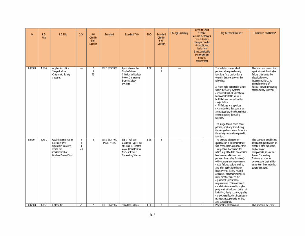
B-3
ID RG-REV
RG Title GDC RG Cited in
SRP Section
Standards Standard Title SDO Standard Cited in
SRP Section
Change Summary
Level of Effort 1=none
2=limited changes 3=substantive
changes needed 4=insufficient design info
5=not applicable 6=new design-
specific requirement
Key Technical Issues*
Comments and Notes*
1.05303 1.53-2 Application of the Single-Failure Criterion to Safety Systems
— 7 8 15
IEEE 379-2000 Application of the Single-Failure Criterion to Nuclear Power Generating Station Safety Systems
IEEE 7 8
— 1 The safety systems shall perform all required safety functions for a design basis event in the presence of the following: a) Any single detectable failure within the safety systems concurrent with all identifiable, but nondetectable failures. b) All failures caused by the single failure. c) All failures and spurious system actions that cause, or are caused by, the design basis event requiring the safety function. The single failure could occur prior to, or at any time during, the design basis event for which the safety system is required to function.
This standard covers the application of the single-failure criterion to the electrical power, instrumentation, and control portions of nuclear power generating station safety systems.
1.07301 1.73-0 Qualification Tests of Electric Valve Operators Installed Inside the Containment of Nuclear Power Plants
1 2 4 23
3 IEEE 382-1972 (ANSI N41.6)
IEEE Trial Use Guide for Type Test of Class 1E Electric Valve Operators for Nuclear Power Generating Stations
IEEE 3 — 1 The primary objective of qualification is to demonstrate with reasonable assurance that safety-related actuators for which a qualified life or condition has been established can perform their safety function(s) without experiencing common-cause failures before, during, and after applicable design basis events. Safety-related actuators, with their interfaces, must meet or exceed the equipment specification requirements. This continued capability is ensured through a program that includes, but is not limited to, design control, quality control, qualification, installation, maintenance, periodic testing, and surveillance.
This standard establishes criteria for qualification of safety-related actuators, and actuator components, in Nuclear Power Generating Stations in order to demonstrate their ability to perform their intended safety functions.
1.07503 1.75-3 Criteria for 21 7 IEEE 384-1992 Standard Criteria IEEE 7 — 1 Physical separation and This standard describes
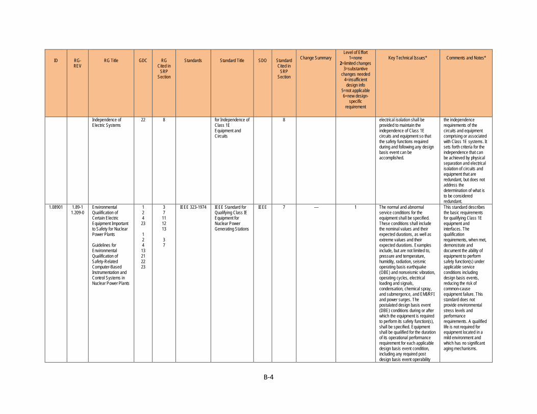
B-4
ID RG-REV
RG Title GDC RG Cited in
SRP Section
Standards Standard Title SDO Standard Cited in
SRP Section
Change Summary
Level of Effort 1=none
2=limited changes 3=substantive
changes needed 4=insufficient design info
5=not applicable 6=new design-
specific requirement
Key Technical Issues*
Comments and Notes*
Independence of Electric Systems
22 8 for Independence of Class 1E Equipment and Circuits
8 electrical isolation shall be provided to maintain the independence of Class 1E circuits and equipment so that the safety functions required during and following any design basis event can be accomplished.
the independence requirements of the circuits and equipment comprising or associated with Class 1E systems. It sets forth criteria for the independence that can be achieved by physical separation and electrical isolation of circuits and equipment that are redundant, but does not address the determination of what is to be considered redundant.
1.08901 1.89-1 1.209-0
Environmental Qualification of Certain Electric Equipment Important to Safety for Nuclear Power Plants Guidelines for Environmental Qualification of Safety-Related Computer-Based Instrumentation and Control Systems in Nuclear Power Plants
1 2 4 23 1 2 4 13 21 22 23
3 7 11 12 13
3 7
IEEE 323-1974 IEEE Standard for Qualifying Class IE Equipment for Nuclear Power Generating Stations
IEEE 7 — 1 The normal and abnormal service conditions for the equipment shall be specified. These conditions shall include the nominal values and their expected durations, as well as extreme values and their expected durations. Examples include, but are not limited to, pressure and temperature, humidity, radiation, seismic operating basis earthquake (OBE) and nonseismic vibration, operating cycles, electrical loading and signals, condensation, chemical spray, and submergence, and EMI/RFI and power surges. The postulated design basis event (DBE) conditions during or after which the equipment is required to perform its safety function(s), shall be specified. Equipment shall be qualified for the duration of its operational performance requirement for each applicable design basis event condition, including any required post design basis event operability
This standard describes the basic requirements for qualifying Class 1E equipment and interfaces. The qualification requirements, when met, demonstrate and document the ability of equipment to perform safety function(s) under applicable service conditions including design basis events, reducing the risk of common-cause equipment failure. This standard does not provide environmental stress levels and performance requirements. A qualified life is not required for equipment located in a mild environment and which has no significant aging mechanisms.
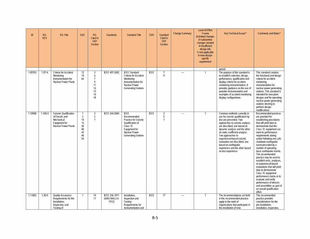
B-5
ID RG-REV
RG Title GDC RG Cited in
SRP Section
Standards Standard Title SDO Standard Cited in
SRP Section
Change Summary
Level of Effort 1=none
2=limited changes 3=substantive
changes needed 4=insufficient design info
5=not applicable 6=new design-
specific requirement
Key Technical Issues*
Comments and Notes*
period. 1.09703 1.97-4 Criteria for Accident
Monitoring Instrumentation for Nuclear Power Plants
13 19 64
3 6 7 9 11 12 13 14 18
IEEE 497-2002 IEEE Standard Criteria for Accident Monitoring Instrumentation for Nuclear Power Generating Stations
IEEE 7 11
— 1 The purpose of this standard is to establish selection, design, performance, qualification and display criteria for accident monitoring instrumentation. It provides guidance on the use of portable instrumentation and examples of accident monitoring display configurations.
This standard contains the functional and design criteria for accident monitoring instrumentation for nuclear power generating stations. This standard is intended for new plant designs and for operating nuclear power generating stations desiring to perform design modifications.
1.10008 1.100-3 Seismic Qualification of Electric and Mechanical Equipment for Nuclear Power Plants
1 2 14 15 30 40 43 46 54
3 5 7
IEEE 344-2004 IEEE Recommended Practice for Seismic Qualification of Class 1E Equipment for Nuclear Power Generating Stations
IEEE 3 5 7
— 1 Common methods currently in use for seismic qualification by test are presented. Two approaches to seismic analysis are described, one based on dynamic analysis and the other on static coefficient analysis. Two approaches to experienced-based seismic evaluation are described, one based on earthquake experience and the other based on test experience.
Recommended practices are provided for establishing procedures that will yield data to demonstrate that the Class 1E equipment can meet its performance requirements during and/or following one safe shutdown earthquake event preceded by a number of operating basis earthquake events. This recommended practice may be used to establish tests, analyses, or experienced-based evaluations that will yield data to demonstrate Class 1E equipment performance claims or to evaluate and verify performance of devices and assemblies as part of an overall qualification effort.
1.11802 1.30-0 Quality Assurance Requirements for the Installation, Inspection, and Testing of
1 14 17
IEEE 336-1971 (ANSI N45.2.4-
1972)
Installation, Inspection and Testing Requirements for Instrumentation and
IEEE 17 — 1 The recommendations set forth in this recommended practice apply to the work of organizations that participate in the installation of new
This recommended practice provides considerations for the pre-installation, installation, inspection,
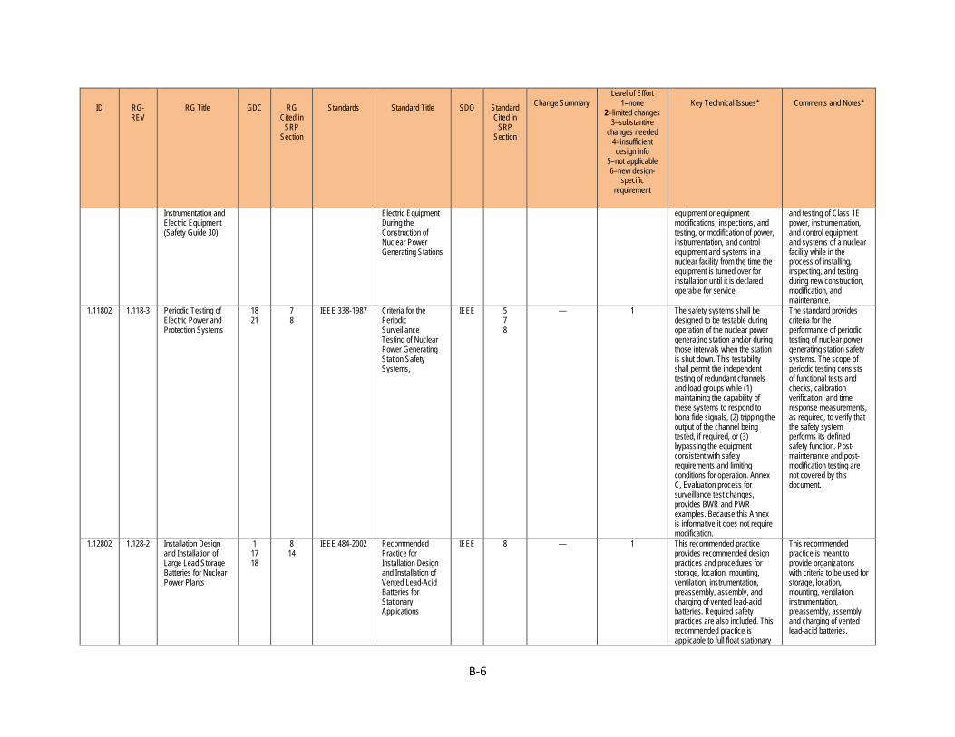
B-6
ID RG-REV
RG Title GDC RG Cited in
SRP Section
Standards Standard Title SDO Standard Cited in
SRP Section
Change Summary
Level of Effort 1=none
2=limited changes 3=substantive
changes needed 4=insufficient design info
5=not applicable 6=new design-
specific requirement
Key Technical Issues*
Comments and Notes*
Instrumentation and Electric Equipment (Safety Guide 30)
Electric Equipment During the Construction of Nuclear Power Generating Stations
equipment or equipment modifications, inspections, and testing, or modification of power, instrumentation, and control equipment and systems in a nuclear facility from the time the equipment is turned over for installation until it is declared operable for service.
and testing of Class 1E power, instrumentation, and control equipment and systems of a nuclear facility while in the process of installing, inspecting, and testing during new construction, modification, and maintenance.
1.11802 1.118-3 Periodic Testing of Electric Power and Protection Systems
18 21
7 8
IEEE 338-1987 Criteria for the Periodic Surveillance Testing of Nuclear Power Generating Station Safety Systems,
IEEE 5 7 8
— 1 The safety systems shall be designed to be testable during operation of the nuclear power generating station and/or during those intervals when the station is shut down. This testability shall permit the independent testing of redundant channels and load groups while (1) maintaining the capability of these systems to respond to bona fide signals, (2) tripping the output of the channel being tested, if required, or (3) bypassing the equipment consistent with safety requirements and limiting conditions for operation. Annex C, Evaluation process for surveillance test changes, provides BWR and PWR examples. Because this Annex is informative it does not require modification.
The standard provides criteria for the performance of periodic testing of nuclear power generating station safety systems. The scope of periodic testing consists of functional tests and checks, calibration verification, and time response measurements, as required, to verify that the safety system performs its defined safety function. Post-maintenance and post-modification testing are not covered by this document.
1.12802 1.128-2 Installation Design and Installation of Large Lead Storage Batteries for Nuclear Power Plants
1 17 18
8 14
IEEE 484-2002 Recommended Practice for Installation Design and Installation of Vented Lead-Acid Batteries for Stationary Applications
IEEE 8 — 1 This recommended practice provides recommended design practices and procedures for storage, location, mounting, ventilation, instrumentation, preassembly, assembly, and charging of vented lead-acid batteries. Required safety practices are also included. This recommended practice is applicable to full float stationary
This recommended practice is meant to provide organizations with criteria to be used for storage, location, mounting, ventilation, instrumentation, preassembly, assembly, and charging of vented lead-acid batteries.
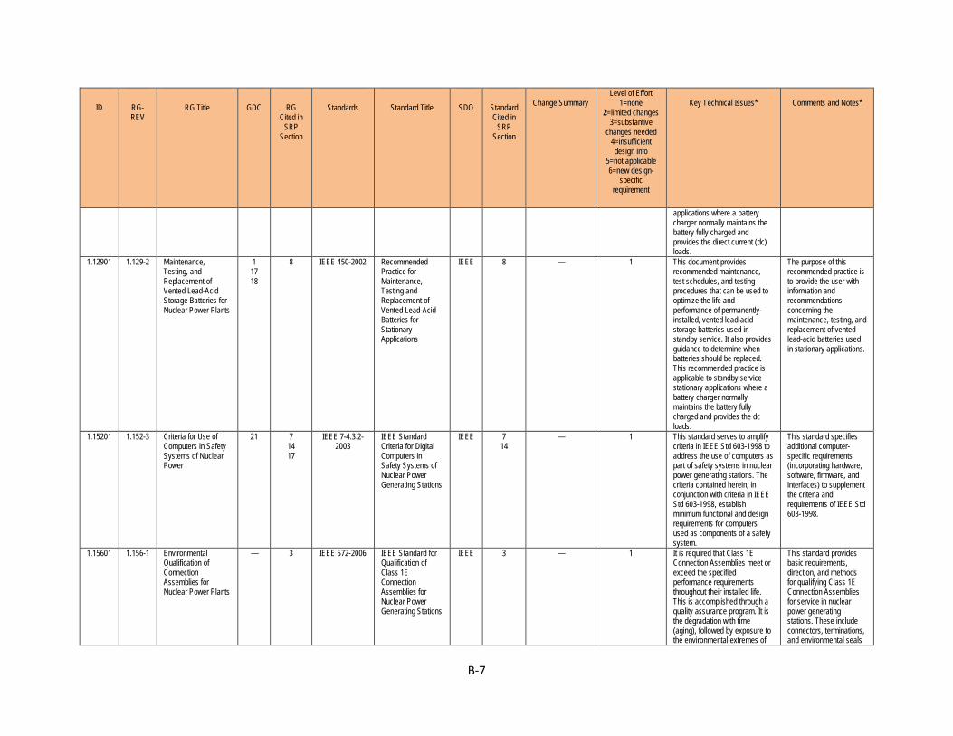
B-7
ID RG-REV
RG Title GDC RG Cited in
SRP Section
Standards Standard Title SDO Standard Cited in
SRP Section
Change Summary
Level of Effort 1=none
2=limited changes 3=substantive
changes needed 4=insufficient design info
5=not applicable 6=new design-
specific requirement
Key Technical Issues*
Comments and Notes*
applications where a battery charger normally maintains the battery fully charged and provides the direct current (dc) loads.
1.12901 1.129-2 Maintenance, Testing, and Replacement of Vented Lead-Acid Storage Batteries for Nuclear Power Plants
1 17 18
8 IEEE 450-2002 Recommended Practice for Maintenance, Testing and Replacement of Vented Lead-Acid Batteries for Stationary Applications
IEEE 8 — 1 This document provides recommended maintenance, test schedules, and testing procedures that can be used to optimize the life and performance of permanently-installed, vented lead-acid storage batteries used in standby service. It also provides guidance to determine when batteries should be replaced. This recommended practice is applicable to standby service stationary applications where a battery charger normally maintains the battery fully charged and provides the dc loads.
The purpose of this recommended practice is to provide the user with information and recommendations concerning the maintenance, testing, and replacement of vented lead-acid batteries used in stationary applications.
1.15201 1.152-3 Criteria for Use of Computers in Safety Systems of Nuclear Power
21 7 14 17
IEEE 7-4.3.2-2003
IEEE Standard Criteria for Digital Computers in Safety Systems of Nuclear Power Generating Stations
IEEE 7 14
— 1 This standard serves to amplify criteria in IEEE Std 603-1998 to address the use of computers as part of safety systems in nuclear power generating stations. The criteria contained herein, in conjunction with criteria in IEEE Std 603-1998, establish minimum functional and design requirements for computers used as components of a safety system.
This standard specifies additional computer-specific requirements (incorporating hardware, software, firmware, and interfaces) to supplement the criteria and requirements of IEEE Std 603-1998.
1.15601 1.156-1 Environmental Qualification of Connection Assemblies for Nuclear Power Plants
— 3 IEEE 572-2006 IEEE Standard for Qualification of Class 1E Connection Assemblies for Nuclear Power Generating Stations
IEEE 3 — 1 It is required that Class 1E Connection Assemblies meet or exceed the specified performance requirements throughout their installed life. This is accomplished through a quality assurance program. It is the degradation with time (aging), followed by exposure to the environmental extremes of
This standard provides basic requirements, direction, and methods for qualifying Class 1E Connection Assemblies for service in nuclear power generating stations. These include connectors, terminations, and environmental seals

B-8
ID RG-REV
RG Title GDC RG Cited in
SRP Section
Standards Standard Title SDO Standard Cited in
SRP Section
Change Summary
Level of Effort 1=none
2=limited changes 3=substantive
changes needed 4=insufficient design info
5=not applicable 6=new design-
specific requirement
Key Technical Issues*
Comments and Notes*
temperature, pressure, humidity, radiation, vibration, or chemical spray resulting from design basis events (DBE), or a combination of these, which presents a potential for causing common-mode failures of Class 1E Connection Assemblies. For these reasons it is necessary to establish a qualified life and qualified condition for Connection Assemblies required to function during and/or following a DBE.
in combination with related cables or wires as assemblies. This standard does not apply to containment electric penetrations, fire stops, in-line splices, or components for service within the reactor vessel. The qualification requirements in this standard, when met, demonstrate and document the ability of the equipment to perform safety function(s) under applicable service conditions (including design basis events) reducing the risks of common cause-equipment failures.
1.15801 1.158-0 Qualification of Safety-Related Lead Storage Batteries for Nuclear Power Plants
1 2 4 23
3 IEEE 535-1986 IEEE Standard for Qualification of Class 1E Lead Storage Batteries for Nuclear Power Generating Stations
IEEE 3 — 1 The users of Class 1E lead storage batteries are required to provide assurance that such equipment meets or exceeds its design specifications throughout its installed life. This is accomplished through a quality assurance program that includes design, qualification, production, quality control, installation, maintenance, and periodic testing.
This standard describes qualification methods for Class 1E vented lead acid batteries and racks to be used in nuclear power generating stations outside primary containment.
1.16804 1.168-1 Verification, Validation, Reviews, and Audits for Digital Computer Software Used in Safety Systems of Nuclear Power Plants
1 7 IEEE 1012-1998
IEEE Standard for Software Verification and Validation
IEEE 7 — 1 The scope of V&V processes encompasses systems, software, and hardware, and it includes their interfaces. This standard applies to systems, software, and hardware being developed, maintained, or reused [legacy, commercial off-the-shelf (COTS), nondevelopmental items]. The term software also includes
Verification and validation (V&V) processes are used to determine whether the development products of a given activity conform to the requirements of that activity and whether the product satisfies its intended use and user needs. V&V life cycle
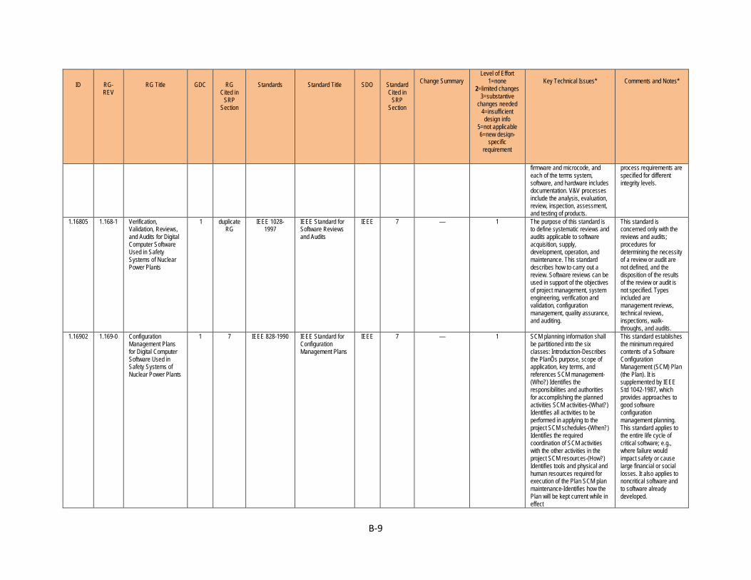
B-9
ID RG-REV
RG Title GDC RG Cited in
SRP Section
Standards Standard Title SDO Standard Cited in
SRP Section
Change Summary
Level of Effort 1=none
2=limited changes 3=substantive
changes needed 4=insufficient design info
5=not applicable 6=new design-
specific requirement
Key Technical Issues*
Comments and Notes*
firmware and microcode, and each of the terms system, software, and hardware includes documentation. V&V processes include the analysis, evaluation, review, inspection, assessment, and testing of products.
process requirements are specified for different integrity levels.
1.16805 1.168-1 Verification, Validation, Reviews, and Audits for Digital Computer Software Used in Safety Systems of Nuclear Power Plants
1 duplicate RG
IEEE 1028-1997
IEEE Standard for Software Reviews and Audits
IEEE 7 — 1 The purpose of this standard is to define systematic reviews and audits applicable to software acquisition, supply, development, operation, and maintenance. This standard describes how to carry out a review. Software reviews can be used in support of the objectives of project management, system engineering, verification and validation, configuration management, quality assurance, and auditing.
This standard is concerned only with the reviews and audits; procedures for determining the necessity of a review or audit are not defined, and the disposition of the results of the review or audit is not specified. Types included are management reviews, technical reviews, inspections, walk-throughs, and audits.
1.16902 1.169-0 Configuration Management Plans for Digital Computer Software Used in Safety Systems of Nuclear Power Plants
1 7 IEEE 828-1990 IEEE Standard for Configuration Management Plans
IEEE 7 — 1 SCM planning information shall be partitioned into the six classes: Introduction-Describes the PlanÕs purpose, scope of application, key terms, and references SCM management-(Who?) Identifies the responsibilities and authorities for accomplishing the planned activities SCM activities-(What?) Identifies all activities to be performed in applying to the project SCM schedules-(When?) Identifies the required coordination of SCM activities with the other activities in the project SCM resources-(How?) Identifies tools and physical and human resources required for execution of the Plan SCM plan maintenance-Identifies how the Plan will be kept current while in effect
This standard establishes the minimum required contents of a Software Configuration Management (SCM) Plan (the Plan). It is supplemented by IEEE Std 1042-1987, which provides approaches to good software configuration management planning. This standard applies to the entire life cycle of critical software; e.g., where failure would impact safety or cause large financial or social losses. It also applies to noncritical software and to software already developed.
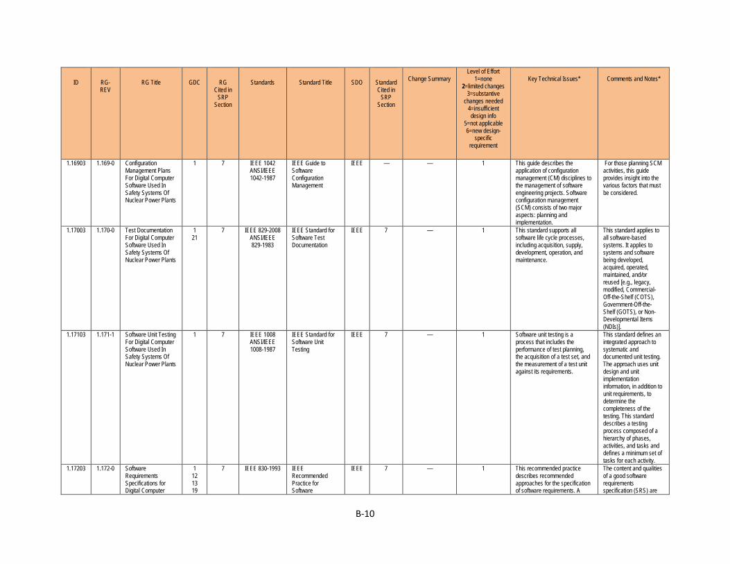
B-10
ID RG-REV
RG Title GDC RG Cited in
SRP Section
Standards Standard Title SDO Standard Cited in
SRP Section
Change Summary
Level of Effort 1=none
2=limited changes 3=substantive
changes needed 4=insufficient design info
5=not applicable 6=new design-
specific requirement
Key Technical Issues*
Comments and Notes*
1.16903 1.169-0 Configuration Management Plans For Digital Computer Software Used In Safety Systems Of Nuclear Power Plants
1 7 IEEE 1042 ANSI/IEEE 1042-1987
IEEE Guide to Software Configuration Management
IEEE — — 1 This guide describes the application of configuration management (CM) disciplines to the management of software engineering projects. Software configuration management (SCM) consists of two major aspects: planning and implementation.
For those planning SCM activities, this guide provides insight into the various factors that must be considered.
1.17003 1.170-0 Test Documentation For Digital Computer Software Used In Safety Systems Of Nuclear Power Plants
1 21
7 IEEE 829-2008 ANSI/IEEE 829-1983
IEEE Standard for Software Test Documentation
IEEE 7 — 1 This standard supports all software life cycle processes, including acquisition, supply, development, operation, and maintenance.
This standard applies to all software-based systems. It applies to systems and software being developed, acquired, operated, maintained, and/or reused [e.g., legacy, modified, Commercial-Off-the-Shelf (COTS), Government-Off-the-Shelf (GOTS), or Non-Developmental Items (NDIs)].
1.17103 1.171-1 Software Unit Testing For Digital Computer Software Used In Safety Systems Of Nuclear Power Plants
1 7 IEEE 1008 ANSI/IEEE 1008-1987
IEEE Standard for Software Unit Testing
IEEE 7 — 1 Software unit testing is a process that includes the performance of test planning, the acquisition of a test set, and the measurement of a test unit against its requirements.
This standard defines an integrated approach to systematic and documented unit testing. The approach uses unit design and unit implementation information, in addition to unit requirements, to determine the completeness of the testing. This standard describes a testing process composed of a hierarchy of phases, activities, and tasks and defines a minimum set of tasks for each activity.
1.17203 1.172-0 Software Requirements Specifications for Digital Computer
1 12 13 19
7 IEEE 830-1993 IEEE Recommended Practice for Software
IEEE 7 — 1 This recommended practice describes recommended approaches for the specification of software requirements. A
The content and qualities of a good software requirements specification (SRS) are

B-11
ID RG-REV
RG Title GDC RG Cited in
SRP Section
Standards Standard Title SDO Standard Cited in
SRP Section
Change Summary
Level of Effort 1=none
2=limited changes 3=substantive
changes needed 4=insufficient design info
5=not applicable 6=new design-
specific requirement
Key Technical Issues*
Comments and Notes*
Software Used in Safety Systems of Nuclear Power Plants
20 22 23 24 25 28
Requirements Specifications
good SRS should provide several specific benefits, such as the following: Establish the basis for agreement between the customers and the suppliers on what the software product is to do, Reduce the development effort, Provide a basis for estimating costs and schedules, Provide a baseline for validation and verification, Facilitate transfer of the software product to new users or new machines, and Serve as a basis for enhancement.
described and several sample SRS outlines are presented. This recommended practice is aimed at specifying requirements of software to be developed but also can be applied to assist in the selection of in-house and commercial software products.
1.17303 1.173-0 Developing Software Life Cycle Processes for Digital Computer Software used in Safety Systems of Nuclear Power Plants
1 7 IEEE 1074-1995
IEEE Standard for Developing Software Life Cycle Processes
IEEE 7 — 1 This standard provides a process for creating a software project life cycle process (SPLCP). This methodology begins with the selection of an appropriate software project life cycle model (SPLCM) for use on the specific project. It continues through the definition of the software project life cycle (SPLC), using the selected SPLCM, the activities provided in Annex A, and the portion of the software life cycle that is relevant to the project. The methodology concludes with the augmentation of the software life cycle with organizational process assets (OPAs) to create the SPLCP.
This standard defines the process by which an SPLCP is developed. It can be used where software is the total system or where software is part of a larger system.
1.18023 1.180-1 1.204-0
Guidelines for Evaluating Electromagnetic and Radio-Frequency Interference in Safety-Related Instrumentation and Control Systems Guidelines for
1 2 4 13 21 22 23
3 7 9
7 8
IEEE 1050-1996
Guide for Instrumentation and Control Equipment Grounding in Generating Stations
IEEE 7 8
— 1 This application guide was developed to identify I&C equipment grounding methods to achieve both a suitable level of protection for personnel and equipment, and suitable electric noise immunity for signal ground references. Grounding design is normally based on the concept of two separate grounding
The typical environment in a generating station provides many sources of electrical noise such as the switching of large inductive loads, high fault currents, electronic drives, and high-energy, high-frequency transients associated with switching
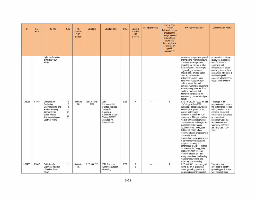
B-12
ID RG-REV
RG Title GDC RG Cited in
SRP Section
Standards Standard Title SDO Standard Cited in
SRP Section
Change Summary
Level of Effort 1=none
2=limited changes 3=substantive
changes needed 4=insufficient design info
5=not applicable 6=new design-
specific requirement
Key Technical Issues*
Comments and Notes*
Lightning Protection of Nuclear Power Plants
systems—the equipment ground and the signal reference ground. The concepts of equipment grounding are covered in other IEEE standards. The concepts of grounding of instrument chassis, cable shields, signal pairs, and other related instrumentation and control items require special care in order to ensure that both personnel working on equipment are adequately protected from electrical shock and that interference signals are not inadvertently coupled into signal circuits.
at transmission voltage levels. The increasing use of solid-state equipment and microprocessor-based control systems in these applications introduces a number of specific concerns with respect to electrical noise control.
1.18025 1.180-1 Guidelines for Evaluating Electromagnetic and Radio-Frequency Interference in Safety-Related Instrumentation and Control Systems
1 2 4 13 21 22 23
duplicate RG
IEEE C62.45-1992
IEEE Recommended Practice on Surge Testing for Equipment Connected to Low-Voltage (1000 V and Less) AC Power Circuits
IEEE 7 — 1 IEEE Std C62.41.1-2002 the first of a Trilogy of three IEEE standards addressing surges in low-voltage ac power circuits, focuses on the surge environment and on the TOV environment. This part provides readers with basic information on the occurrence of surges, as a database for the second document of the Trilogy, IEEE Std C62.41.2-2002 where recommendations are presented on the selection of representative surge parameters to be considered in assessing equipment immunity and performance of SPDs. The third document of the Trilogy, IEEE Std C62.45-2002, presents recommendations on surge testing procedures for obtaining reliable measurements and enhancing operator safety.
The scope of this recommended practice is the performance of surge testing on electrical and electronic equipment connected to low-voltage ac power circuits, specifically using the recommended test waveforms defined in IEEE Std C62.41.2™-2002.
1.20403 1.204-0 Guidelines for Lightning Protection of Nuclear Power Plants
2 duplicate RG
IEEE 665-1995 IEEE Guide for Generating Station Grounding
IEEE 7 8
— 1 IEEE 665-1005 provides a guide for the design of generating station grounding systems and for grounding practices applied
This guide was developed to identify grounding practices that have generally been
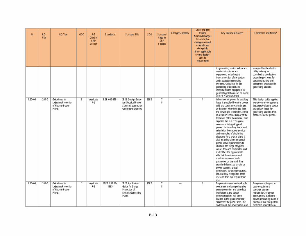
B-13
ID RG-REV
RG Title GDC RG Cited in
SRP Section
Standards Standard Title SDO Standard Cited in
SRP Section
Change Summary
Level of Effort 1=none
2=limited changes 3=substantive
changes needed 4=insufficient design info
5=not applicable 6=new design-
specific requirement
Key Technical Issues*
Comments and Notes*
to generating station indoor and outdoor structures and equipment, including the interconnection of the station and substation grounding systems. Guidance for the grounding of control and instrumentation equipment in generating stations can be found in IEEE Std 1050-1989.
accepted by the electric utility industry as contributing to effective grounding systems for personnel safety and equipment protection in generating stations.
1.20404 1.204-0 Guidelines for Lightning Protection of Nuclear Power Plants
2 duplicate RG
IEEE 666-1991 IEEE Design Guide for Electrical Power Service Systems for Generating Stations
IEEE 7 8
— 1 When electric power for auxiliary loads is supplied from the power grid, the service system begins at the point where the tap from the power grid terminates, either at a station service bus or at the terminals of the transformer that supplies the bus. This guide contains a listing of typical power plant auxiliary loads and criteria for their power service and examples of single-line diagrams for a typical plant. It also includes tables of typical power service parameters to illustrate the range of typical values for each parameter, and it identifies the approximate effect of the minimum and maximum value of each parameter on the load. The standard discusses on-site ac power sources, diesel generators, turbine generators, etc. but only recognizes there use and does not require their use.
This design guide applies to station service systems that supply electric power to auxiliary loads for generating stations that produce electric power.
1.20406 1.204-0 Guidelines for Lightning Protection of Nuclear Power Plants
2 duplicate RG
IEEE C62.23-1995
IEEE Application Guide for Surge Protection of Electric Generating Plants
IEEE 7 8
— 1 To provide an understanding for consistent and comprehensive surge protection and to reduce interference, the power generating plant has been divided in this guide into four subareas: the power lines, the switchyard, the power plant, and
Surge overvoltages can cause equipment damage, system malfunction, or power interruptions at electric power generating plants if plants are not adequately protected against them.

B-14
ID RG-REV
RG Title GDC RG Cited in
SRP Section
Standards Standard Title SDO Standard Cited in
SRP Section
Change Summary
Level of Effort 1=none
2=limited changes 3=substantive
changes needed 4=insufficient design info
5=not applicable 6=new design-
specific requirement
Key Technical Issues*
Comments and Notes*
the remote ancillary systems. Within each subarea, the “surge environment” in which the associated equipment and systems are required to operate is addressed in terms of the common overvoltage and electromagnetic interference sources identified below: — Direct lightning strokes — Incoming surges — Internally generated surges — Ground potential rise — Electromagnetic interference
Excessive surge voltages have to, therefore, be controlled or reduced to permissible levels. These overvoltage surges in power generating plants may be generated by lightning or by system events such as switching, faults, load rejections, or by some combinations of these.
1.21001 1.210-0 Qualification of Safety-Related Battery Chargers and Inverters for Nuclear Power Plants
2 4 23
— IEEE 650-2006 IEEE Standard for Qualification of Class 1E Static Battery Chargers and Inverters for Nuclear Power Generating Stations
IEEE — — 1 Specifications for the equipment to be qualified include the equipment identification, the Class 1E performance characteristics, the input power supply, the environmental conditions, and the effect of changes in input power supply and environmental conditions upon the Class 1E performance characteristics. If the equipment specification includes margins, their values shall be identified.
This standard describes methods for qualifying static battery chargers and inverters for Class 1E installations outside containment in nuclear power generating stations.
1.21101 1.211-0 Qualification of Safety-Related Cables and Field Splices for Nuclear Power Plants
2 4 23
— IEEE 383-2003 IEEE Standard for Qualifying Class 1E Electric Cables and Field Splices for Nuclear Power Generating Stations
IEEE 3 9
— 1 Degradation with time (aging), followed by exposure to the environmental extremes of temperature, pressure, humidity, radiation, mechanical stress, or chemical spray or a combination of these resulting from DBEs present a potential for common-cause failures of Class 1E cable and splices. A qualified life is not required for cables and splices located in a mild environment, if the cables and splices are operated within the limits established by applicable specifications and standards. Qualification by analysis alone is not acceptable.
This standard provides general requirements and methods for qualifying electric cables, and splices for nuclear facilities. An objective of qualification is to establish a qualified life for cables and splices that are installed in environmentally harsh areas and must perform a safety function during and following a DBE.
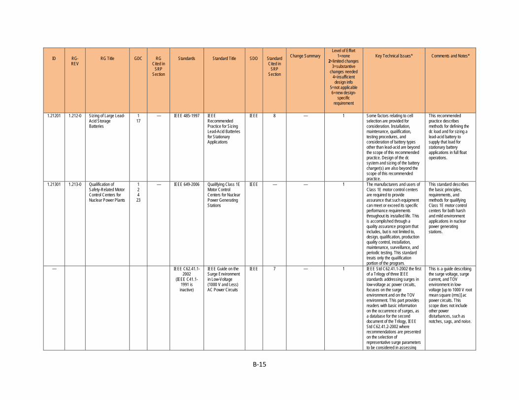
B-15
ID RG-REV
RG Title GDC RG Cited in
SRP Section
Standards Standard Title SDO Standard Cited in
SRP Section
Change Summary
Level of Effort 1=none
2=limited changes 3=substantive
changes needed 4=insufficient design info
5=not applicable 6=new design-
specific requirement
Key Technical Issues*
Comments and Notes*
1.21201 1.212-0 Sizing of Large Lead-Acid Storage Batteries
1 17
— IEEE 485-1997 IEEE Recommended Practice for Sizing Lead-Acid Batteries for Stationary Applications
IEEE 8 — 1 Some factors relating to cell selection are provided for consideration. Installation, maintenance, qualification, testing procedures, and consideration of battery types other than lead-acid are beyond the scope of this recommended practice. Design of the dc system and sizing of the battery charger(s) are also beyond the scope of this recommended practice.
This recommended practice describes methods for defining the dc load and for sizing a lead-acid battery to supply that load for stationary battery applications in full float operations.
1.21301 1.213-0 Qualification of Safety-Related Motor Control Centers for Nuclear Power Plants
1 2 4 23
— IEEE 649-2006 Qualifying Class 1E Motor Control Centers for Nuclear Power Generating Stations
IEEE — — 1 The manufacturers and users of Class 1E motor control centers are required to provide assurance that such equipment can meet or exceed its specific performance requirements throughout its installed life. This is accomplished through a quality assurance program that includes, but is not limited to, design, qualification, production quality control, installation, maintenance, surveillance, and periodic testing. This standard treats only the qualification portion of the program.
This standard describes the basic principles, requirements, and methods for qualifying Class 1E motor control centers for both harsh and mild environment applications in nuclear power generating stations.
— IEEE C62.41.1-2002
(IEEE C41.1-1991 is inactive)
IEEE Guide on the Surge Environment in Low-Voltage (1000 V and Less) AC Power Circuits
IEEE 7 — 1 IEEE Std C62.41.1-2002 the first of a Trilogy of three IEEE standards addressing surges in low-voltage ac power circuits, focuses on the surge environment and on the TOV environment. This part provides readers with basic information on the occurrence of surges, as a database for the second document of the Trilogy, IEEE Std C62.41.2-2002 where recommendations are presented on the selection of representative surge parameters to be considered in assessing
This is a guide describing the surge voltage, surge current, and TOV environment in low-voltage [up to 1000 V root mean square (rms)] ac power circuits. This scope does not include other power disturbances, such as notches, sags, and noise.
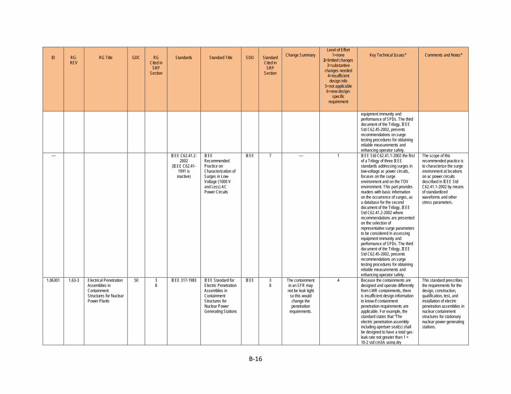
B-16
ID RG-REV
RG Title GDC RG Cited in
SRP Section
Standards Standard Title SDO Standard Cited in
SRP Section
Change Summary
Level of Effort 1=none
2=limited changes 3=substantive
changes needed 4=insufficient design info
5=not applicable 6=new design-
specific requirement
Key Technical Issues*
Comments and Notes*
equipment immunity and performance of SPDs. The third document of the Trilogy, IEEE Std C62.45-2002, presents recommendations on surge testing procedures for obtaining reliable measurements and enhancing operator safety.
— IEEE C62.41.2-2002
(IEEE C62.41-1991 is inactive)
IEEE Recommended Practice on Characterization of Surges in Low-Voltage (1000 V and Less) AC Power Circuits
IEEE 7 — 1 IEEE Std C62.41.1-2002 the first of a Trilogy of three IEEE standards addressing surges in low-voltage ac power circuits, focuses on the surge environment and on the TOV environment. This part provides readers with basic information on the occurrence of surges, as a database for the second document of the Trilogy, IEEE Std C62.41.2-2002 where recommendations are presented on the selection of representative surge parameters to be considered in assessing equipment immunity and performance of SPDs. The third document of the Trilogy, IEEE Std C62.45-2002, presents recommendations on surge testing procedures for obtaining reliable measurements and enhancing operator safety.
The scope of this recommended practice is to characterize the surge environment at locations on ac power circuits described in IEEE Std C62.41.1-2002 by means of standardized waveforms and other stress parameters.
1.06301 1.63-3 Electrical Penetration Assemblies in Containment Structures for Nuclear Power Plants
50 3 8
IEEE 317-1983 IEEE Standard for Electric Penetration Assemblies in Containment Structures for Nuclear Power Generating Stations
IEEE 3 8
The containment in an SFR may not be leak tight
so this would change the penetration
requirements.
4 Because the containments are designed and operate differently from LWR containments, there is insufficient design information to know if containment penetration requirements are applicable. For example, the standard states that “The electric penetration assembly including aperture seal(s) shall be designed to have a total gas-leak rate not greater than 1 × 10⁻² std cm3/s using dry
This standard prescribes the requirements for the design, construction, qualification, test, and installation of electric penetration assemblies in nuclear containment structures for stationary nuclear power generating stations.

B-17
ID RG-REV
RG Title GDC RG Cited in
SRP Section
Standards Standard Title SDO Standard Cited in
SRP Section
Change Summary
Level of Effort 1=none
2=limited changes 3=substantive
changes needed 4=insufficient design info
5=not applicable 6=new design-
specific requirement
Key Technical Issues*
Comments and Notes*
nitrogen at design pressure and ambient temperature after installation and after any DBEs (excluding direct steam jet impingement).” SFRs may not have or need this requirement, or it may be relaxed.
1.00901 1.9-4 Application and Testing of Safety-Related Diesel Generators in Nuclear Power Plants
17 18
8 IEEE 387-1995 IEEE Standard Criteria for Diesel-Generator Units Applied as Standby Power Supplies for Nuclear Power Generating Stations
IEEE 8 Diesel generators in the new plant designs may or
may not be safety-related.
4 The purpose of this standard is to provide the principal design criteria, the design features, testing, and qualification requirements for the individual diesel-generator units that enable them to meet their functional requirements as a part of the standby power supply under the conditions produced by the design basis events cataloged in the Plant Safety Analysis.
This standard describes the criteria for the application and testing of diesel-generator units as Class 1E standby power supplies in nuclear power generating stations.
1.03002 1.30-0 Quality Assurance Requirements For The Installation, Inspection, And Testing Of Instrumentation And Electric Equipment
— 14 17
IEEE 336-1971 (ANSI N45.2.4-
1972)
IEEE Recommended Practice for Installation, Inspection, and Testing for Class 1E Power, Instrumentation, and Control Equipment at Nuclear Facilities
IEEE — — duplicate
—
1.04701 1.47-1
IEEE 603-1991 IEEE Standard Criteria for Safety Systems for Nuclear Power Generating Stations
IEEE — — duplicate
—
1.17103 1.171-0 Software Unit Testing For Digital Computer Software Used In Safety Systems Of Nuclear Power Plants
IEEE 1008 ANSI/IEEE 1008-1987
IEEE Standard for Software Unit Testing
IEEE — — duplicate
—
1.20405 1.204-0 Guidelines for Lightning Protection of Nuclear Power Plants
IEEE 1050-1996
IEEE Guide for Instrumentation and Control Equipment Grounding in
IEEE — — duplicate
—
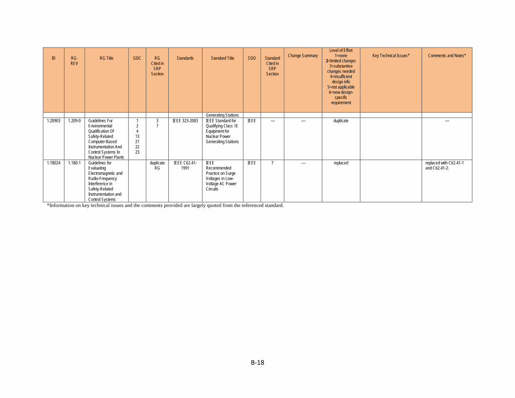
B-18
ID RG-REV
RG Title GDC RG Cited in
SRP Section
Standards Standard Title SDO Standard Cited in
SRP Section
Change Summary
Level of Effort 1=none
2=limited changes 3=substantive
changes needed 4=insufficient design info
5=not applicable 6=new design-
specific requirement
Key Technical Issues*
Comments and Notes*
Generating Stations 1.20903 1.209-0 Guidelines For
Environmental Qualification Of Safety-Related Computer-Based Instrumentation And Control Systems In Nuclear Power Plants
1 2 4 13 21 22 23
3 7
IEEE 323-2003 IEEE Standard for Qualifying Class 1E Equipment for Nuclear Power Generating Stations
IEEE — — duplicate
—
1.18024 1.180-1 Guidelines for Evaluating Electromagnetic and Radio-Frequency Interference in Safety-Related Instrumentation and Control Systems
duplicate RG
IEEE C62.41-1991
IEEE Recommended Practice on Surge Voltages in Low-Voltage AC Power Circuits
IEEE 7 — replaced replaced with C62.41-1 and C62.41-2.
*Information on key technical issues and the comments provided are largely quoted from the referenced standard.