Assembly procedure of the HT-7U device
5
Fusion Engineering and Design 58–59 (2001) 833–837 Assembly procedure of the HT-7U device S.T. Wu * Institute of Plasma Physics, Chinese Academy of Sciences, P.O. Box 1126, Hefei, Anhui 230031, PR China Abstract The HT-7U superconducting tokamak device mainly consists of superconducting magnets of poloidal and toroidal field, vacuum vessel, thermal radiation shields and cryostat vessel. For its complicated constitution and important influence on the design of the main components, a reasonable assembly procedure of the HT-7U device should be defined carefully. The large size and mass of components with tight installation tolerances results in complicated assembly procedure. Before the assembly procedure, a reference coordinate system will be defined with three fiducial targets on the wall of the test hall by a sophisticated optical metrology system (SOMS). All main components of the device will be installed with respect to this coordinate system. Assembly procedure of one quadrant of the TF subassembly each time in turn with the temporary support is suggested. In this way, an existing 50-ton bridge crane can move all components without necessity of special handling tools. In this paper, a procedure of the HT-7U assembly with one quadrant of the TF subassembly is described. © 2001 Elsevier Science B.V. All rights reserved. Keywords: HT-7U device; Vacuum vessel (VV); Tokamak www.elsevier.com/locate/fusengdes 1. Introduction The HT-7U superconducting tokamak device is in the engineering design phase. Based on the requirement of physics design and the preliminary engineering design, the final definition of the device design is being made. The device consists of superconducting poloidal field (PF) magnet system and toroidal field (TF) magnet system, vacuum vessel (VV), thermal radiation shields (TRS) and cryostat vessel (CV). For its compli- cated constitution, the procedure of the HT-7U device assembly will have influence on the struc- ture design of the main parts, the design of the special tools for assembly, even on the installation tolerances and schedule. Therefore, a reasonable assembly procedure of the HT-7U device should be defined carefully. Now at least three possible assembly procedures have been submitted, that is, the final assembly of the HT-7U device can be fulfilled by four quadrant TF subassemblies or eight octant TF subassemblies, or even by each TF coil subassembly one time in turn. Above three procedures are feasible, usually say, but still have some different technologies especially for superconducing tokamaks. The assembly proce- dure by four quadrants of the TF subassembly that contains a quadrant of VV and a quadrant of TRS is introduced in following sections. * Tel.: +86-551-559-2737; fax: +86-551-559-1310. E-mail address: [email protected] (S.T. Wu). 0920-3796/01/$ - see front matter © 2001 Elsevier Science B.V. All rights reserved. PII:S0920-3796(01)00480-X
Transcript of Assembly procedure of the HT-7U device
Fusion Engineering and Design 58–59 (2001) 833–837
Assembly procedure of the HT-7U device
S.T. Wu *Institute of Plasma Physics, Chinese Academy of Sciences, P.O. Box 1126, Hefei, Anhui 230031, PR China
Abstract
The HT-7U superconducting tokamak device mainly consists of superconducting magnets of poloidal and toroidalfield, vacuum vessel, thermal radiation shields and cryostat vessel. For its complicated constitution and importantinfluence on the design of the main components, a reasonable assembly procedure of the HT-7U device should bedefined carefully. The large size and mass of components with tight installation tolerances results in complicatedassembly procedure. Before the assembly procedure, a reference coordinate system will be defined with three fiducialtargets on the wall of the test hall by a sophisticated optical metrology system (SOMS). All main components of thedevice will be installed with respect to this coordinate system. Assembly procedure of one quadrant of the TFsubassembly each time in turn with the temporary support is suggested. In this way, an existing 50-ton bridge cranecan move all components without necessity of special handling tools. In this paper, a procedure of the HT-7Uassembly with one quadrant of the TF subassembly is described. © 2001 Elsevier Science B.V. All rights reserved.
Keywords: HT-7U device; Vacuum vessel (VV); Tokamak
www.elsevier.com/locate/fusengdes
1. Introduction
The HT-7U superconducting tokamak device isin the engineering design phase. Based on therequirement of physics design and the preliminaryengineering design, the final definition of thedevice design is being made. The device consistsof superconducting poloidal field (PF) magnetsystem and toroidal field (TF) magnet system,vacuum vessel (VV), thermal radiation shields(TRS) and cryostat vessel (CV). For its compli-cated constitution, the procedure of the HT-7U
device assembly will have influence on the struc-ture design of the main parts, the design of thespecial tools for assembly, even on the installationtolerances and schedule. Therefore, a reasonableassembly procedure of the HT-7U device shouldbe defined carefully. Now at least three possibleassembly procedures have been submitted, that is,the final assembly of the HT-7U device can befulfilled by four quadrant TF subassemblies oreight octant TF subassemblies, or even by eachTF coil subassembly one time in turn. Abovethree procedures are feasible, usually say, but stillhave some different technologies especially forsuperconducing tokamaks. The assembly proce-dure by four quadrants of the TF subassemblythat contains a quadrant of VV and a quadrant ofTRS is introduced in following sections.
* Tel.: +86-551-559-2737; fax: +86-551-559-1310.E-mail address: [email protected] (S.T. Wu).
0920-3796/01/$ - see front matter © 2001 Elsevier Science B.V. All rights reserved.
PII: S0920 -3796 (01 )00480 -X

S.T. Wu / Fusion Engineering and Design 58–59 (2001) 833–837834
2. Some considerations
For the configuration of the HT-7U device, thekey to the settlement of the assembly procedure isselection of the different subassembly ways of theTF magnets, the VV body and the inner TRS.The main cross-section of the HT-7U device isshown in Fig. 1.
The assembly procedure by four quadrants ofthe TF subassembly with one quadrant of VV andone quadrant of TRS is considered in detail. Theadvantages, in this way, are as following:� Because the subassembly accuracy of the TF
quadrant can be adjusted on a subassemblyplatform before it is installed on the support ofthe cold mass, it will be easier to ensure theassembly of the TF tore for required accuracy.
� One quadrant VV consisting of four sections ofVV could be made by argon arc welding out-side VV or inside VV conveniently withoutaccess limitations, so the distortion of the weld-ing can be controlled effectively.
� Stress-relief and shaping may be carried outbefore the quadrants of VV are installed onsubassembly site. It will benefit to have betteraccuracy of the assembly of VV.
� As the reasons above, it is more convenient forone quadrant of the inner TRS to be made byconnecting sections outside the inner TRS.Also, the processes of stress-relief and shapingmay be carried on before the quadrant of theinner TRS is installed inside the TF quadrant.
� Cross-welding-point on VV could be avoidedon the assembly site. That will benefit thereliability of the welding quality for the weld-ing inside the vacuum vessel on site.The main shortages of one quadrant TF sub-
assembly are as following:� It is impossible to disassemble one TF coil
from the TF tore. Instead, the TF tore onlycan be disassembled in quadrants, if one TFcoil is failed and has to be changed.
� It is not easy for one quadrant TF subassemblywith quadrants of VV and TRS to be installedin alignment of lower vertical ports of VV andTRS.
� Also, the position adjustments of VV and TRSinside the quadrant TF subassembly on sitehave to be achieved by special tools for weightsof one VV quadrant and one TRS quadrantare 3 and 1 ton separately.A sophisticated optical metrology system
(SOMS) will be adopted to setup a referencecoordinate system with the assembly base. Duringthe engineering design of the HT-7U device, notonly the assembly datum plane of each main partshould be defined, but also the specified points ofthe measured target on each main part should bedefined as the measured datum points based.SOMS can also be used to inspect and measurethe size and the contour of each important part ofthe HT-7U device during the fabrication phase.With actual size and shape of each main part, theactual 3D modules can be made by CAD soft-ware. So, an assembly procedure can be simulatedby computer to predict the assembly precisionbefore the real assembly is carried out.
3. Brief description of assembly procedure
The assembly procedure of the HT-7U device isconstituted of three sub-procedures that are thesupports assembly procedure, the TF quadrantFig. 1. The main cross-section of the HT-7U Device.

S.T. Wu / Fusion Engineering and Design 58–59 (2001) 833–837 835
Fig. 2. Supports on the base of CV.
blies a temporary support should be installed inthe centre of the CV base.
3.2. TF quadrant subassembly procedure
On a subassembly platform, four TF coils willbe jointed into a quadrant by connecting theinter-coil structures that are designed with cus-tomized shear pins and shimmed wedges for coilsposition tolerances compensation. Next, a quad-rant of the inner TRS without ports shields isrotated into the quadrant of TF. And two lowershield ports of TRS that are corresponding to thetwo lower support ports of VV will be connectedto the quadrant of the inner TRS from the bot-tom. The two lower shield ports may be welded orbolted with the inner TRS inside it conveniently.Then a quadrant of VV body constituted by foursegments is rotated into to the quadrant of theinner TRS. With a transient section of VV insidethe quadrant of the VV body the TF quadrantsubassembly is finished. Because the weights ofthe quadrant of the inner TRS and the quadrantof the VV body are about 1 and 3 ton separately,specialized tooling has to be used to support andadjust each quadrant of VV and TRS. The specialtooling that is attached to the TF coil case, can beremoved after the tores of the VV body and theinner TRS are formed and in their correctpositions.
subassembly procedure and the final assemblyprocedure. At the beginning of the assembly, avirtual coordinate system will be defined withrespect to the assembly base. Three or fourfiducial targets on the wall of the test hall shouldbe defined with reference of the coordinate systemby SOMS.
3.1. Supports assembly procedure
During the phase of the supports assemblyprocedure, the base of CV will be installed on thedevice support platform. Because a transition portfor inlet and outlet of current bars and heliumpipes are trapped on the bottom of HT-7U, itshould be installed to the central port of the CVbase. Following is the installation and position ofthe supports for VV, the cold mass and TRS. Fig.2 shows the supports of the cold mass, TRS andVV on the base of CV. After alignment andadjustment for all supports, the base part of TRSwill be installed on the supports of TRS. Andthen four lower support ports of the inner TRSwill be installed on the TRS base. A circle sup-port, which is spliced into two halves by insula-tion structures, will be installed on the lowersupports of the cold mass.
Since three lower PF coils are attached underthe TF tore assembly, they should be stored onthe base of TRS temporary, seeing Fig. 3. Also,for the installation of the TF quadrant subassem-
Fig. 3. The lower supports of TRS and the lower PF coils onthe base of TRS.
S.T. Wu / Fusion Engineering and Design 58–59 (2001) 833–837836
3.3. Final assembly procedure
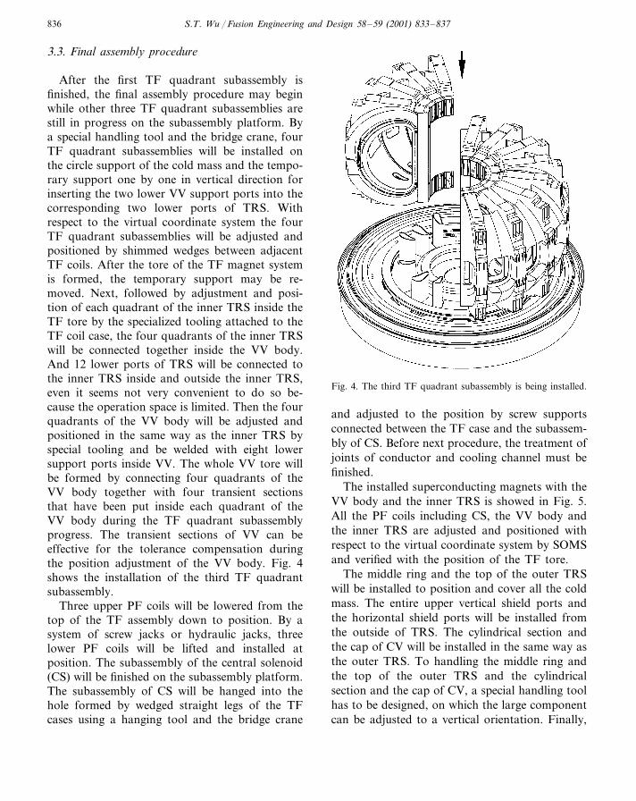
After the first TF quadrant subassembly isfinished, the final assembly procedure may beginwhile other three TF quadrant subassemblies arestill in progress on the subassembly platform. Bya special handling tool and the bridge crane, fourTF quadrant subassemblies will be installed onthe circle support of the cold mass and the tempo-rary support one by one in vertical direction forinserting the two lower VV support ports into thecorresponding two lower ports of TRS. Withrespect to the virtual coordinate system the fourTF quadrant subassemblies will be adjusted andpositioned by shimmed wedges between adjacentTF coils. After the tore of the TF magnet systemis formed, the temporary support may be re-moved. Next, followed by adjustment and posi-tion of each quadrant of the inner TRS inside theTF tore by the specialized tooling attached to theTF coil case, the four quadrants of the inner TRSwill be connected together inside the VV body.And 12 lower ports of TRS will be connected tothe inner TRS inside and outside the inner TRS,even it seems not very convenient to do so be-cause the operation space is limited. Then the fourquadrants of the VV body will be adjusted andpositioned in the same way as the inner TRS byspecial tooling and be welded with eight lowersupport ports inside VV. The whole VV tore willbe formed by connecting four quadrants of theVV body together with four transient sectionsthat have been put inside each quadrant of theVV body during the TF quadrant subassemblyprogress. The transient sections of VV can beeffective for the tolerance compensation duringthe position adjustment of the VV body. Fig. 4shows the installation of the third TF quadrantsubassembly.
Three upper PF coils will be lowered from thetop of the TF assembly down to position. By asystem of screw jacks or hydraulic jacks, threelower PF coils will be lifted and installed atposition. The subassembly of the central solenoid(CS) will be finished on the subassembly platform.The subassembly of CS will be hanged into thehole formed by wedged straight legs of the TFcases using a hanging tool and the bridge crane
Fig. 4. The third TF quadrant subassembly is being installed.
and adjusted to the position by screw supportsconnected between the TF case and the subassem-bly of CS. Before next procedure, the treatment ofjoints of conductor and cooling channel must befinished.
The installed superconducting magnets with theVV body and the inner TRS is showed in Fig. 5.All the PF coils including CS, the VV body andthe inner TRS are adjusted and positioned withrespect to the virtual coordinate system by SOMSand verified with the position of the TF tore.
The middle ring and the top of the outer TRSwill be installed to position and cover all the coldmass. The entire upper vertical shield ports andthe horizontal shield ports will be installed fromthe outside of TRS. The cylindrical section andthe cap of CV will be installed in the same way asthe outer TRS. To handling the middle ring andthe top of the outer TRS and the cylindricalsection and the cap of CV, a special handling toolhas to be designed, on which the large componentcan be adjusted to a vertical orientation. Finally,

S.T. Wu / Fusion Engineering and Design 58–59 (2001) 833–837 837
Fig. 5. Installed superconducting magnets including CS.Fig. 6. The installed HT-7U device.
12 upper ports, 12 horizontal ports and residualfour lower ports will be inserted into their corre-sponding shield ports of TRS from the outside ofCV. After connecting all the ports with VV andCV, the assembly procedure of the main parts ofthe HT-7U device is finished, seeing Fig. 6.
4. Summary
Up to now, three possible assembly procedureshave been submitted, that is the final assembly ofthe HT-7U device can be fulfilled by four quad-rant TF subassemblies or eight octant TF sub-
assemblies, or even by each TF coil subassembly.The assembly procedure by four quadrants of theTF subassembly that contains VV quadrants andTRS quadrants is considered in detail. The finaldefinition of the HT-7U device assembly will bemade in the near future.
Acknowledgements
The work described in this paper is the part ofthe engineering design of the HT-7U device that issupported by Chinese Plan and DevelopmentCommittee.


![OPNAVINST 3710[1].7U IC 39](https://static.fdocuments.us/doc/165x107/553d1a7c4a7959f87e8b4bca/opnavinst-371017u-ic-39.jpg)