Assembly Procedure Electrical Specification DATA...
1
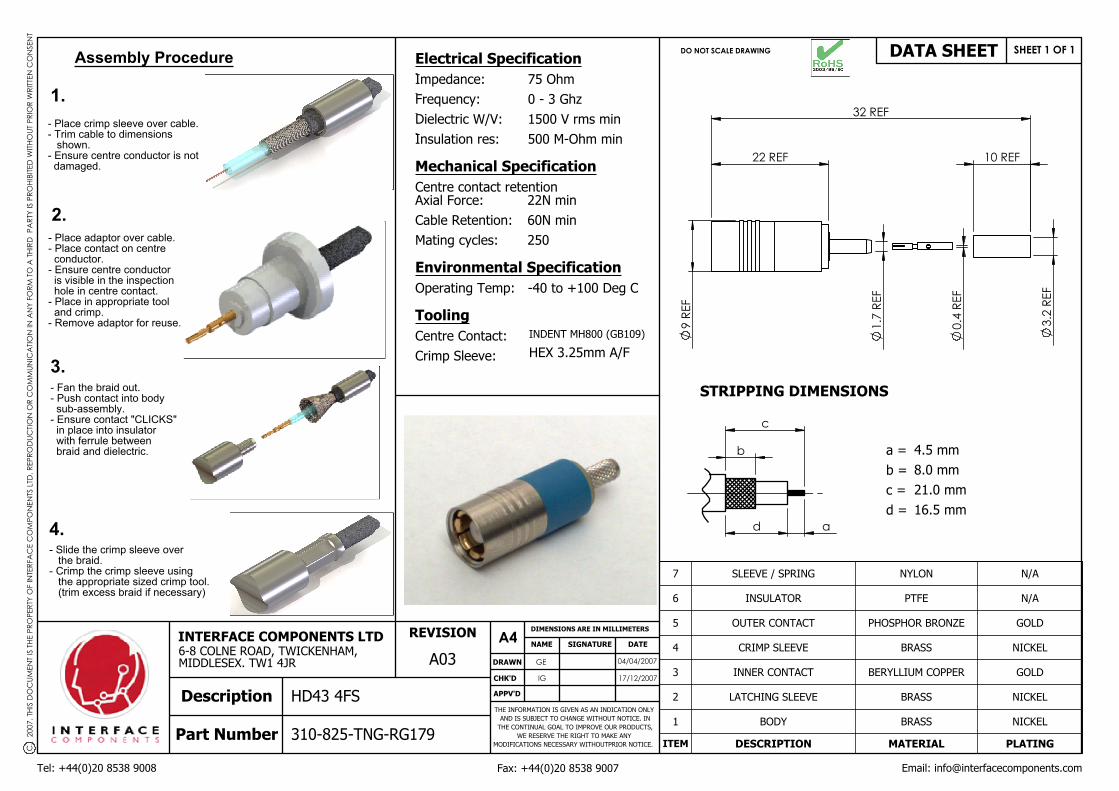
c b a d 32 REF 1.7 REF 3.2 REF 0.4 REF 9 REF 22 REF 10 REF 7 SLEEVE / SPRING NYLON N/A 6 INSULATOR PTFE N/A 5 OUTER CONTACT PHOSPHOR BRONZE GOLD 4 CRIMP SLEEVE BRASS NICKEL 3 INNER CONTACT BERYLLIUM COPPER GOLD 2 LATCHING SLEEVE BRASS NICKEL 1 BODY BRASS NICKEL ITEM DESCRIPTION MATERIAL PLATING DRAWN CHK'D APPV'D DIMENSIONS ARE IN MILLIMETERS NAME SIGNATURE DATE DO NOT SCALE DRAWING REVISION SHEET 1 OF 1 A4 GE IG 04/04/2007 17/12/2007 310-825-TNG-RG179 HD43 4FS Description Part Number A03 INTERFACE COMPONENTS LTD 6-8 COLNE ROAD, TWICKENHAM, MIDDLESEX. TW1 4JR THE INFORMATION IS GIVEN AS AN INDICATION ONLY AND IS SUBJECT TO CHANGE WITHOUT NOTICE. IN THE CONTINUAL GOAL TO IMPROVE OUR PRODUCTS, WE RESERVE THE RIGHT TO MAKE ANY MODIFICATIONS NECESSARY WITHOUTPRIOR NOTICE. Tel: +44(0)20 8538 9008 Fax: +44(0)20 8538 9007 Email: [email protected] DATA SHEET Electrical Specification Impedance: Frequency: Dielectric W/V: Insulation res: Mechanical Specification Centre contact retention Axial Force: Cable Retention: Mating cycles: Environmental Specification Operating Temp: Tooling Centre Contact: Crimp Sleeve: 75 Ohm 0 - 3 Ghz 1500 V rms min 500 M-Ohm min 22N min 60N min 250 -40 to +100 Deg C INDENT MH800 (GB109) HEX 3.25mm A/F STRIPPING DIMENSIONS a = b = c = d = 4.5 mm 8.0 mm 21.0 mm 16.5 mm C. 2007. THIS DOCUMENT IS THE PROPERTY OF INTERFACE COMPONENTS LTD. REPRODUCTION OR COMMUNICATION IN ANY FORM TO A THIRD PARTY IS PROHIBITED WITHOUT PRIOR WRITTEN CONSENT - Place adaptor over cable. - Place contact on centre conductor. - Ensure centre conductor is visible in the inspection hole in centre contact. - Place in appropriate tool and crimp. - Remove adaptor for reuse. - Place crimp sleeve over cable. - Trim cable to dimensions shown. - Ensure centre conductor is not damaged. - Slide the crimp sleeve over the braid. - Crimp the crimp sleeve using the appropriate sized crimp tool. (trim excess braid if necessary) Assembly Procedure - Fan the braid out. - Push contact into body sub-assembly. - Ensure contact "CLICKS" in place into insulator with ferrule between braid and dielectric. 1. 2. 3. 4.
-
Upload
nguyendang -
Category
Documents
-
view
240 -
download
6
Transcript of Assembly Procedure Electrical Specification DATA...
c
b
ad
32 REF
1.7
REF
3.2
REF
0.4
REF
9 RE
F
22 REF 10 REF
7 SLEEVE / SPRING NYLON N/A
6 INSULATOR PTFE N/A
5 OUTER CONTACT PHOSPHOR BRONZE GOLD
4 CRIMP SLEEVE BRASS NICKEL
3 INNER CONTACT BERYLLIUM COPPER GOLD
2 LATCHING SLEEVE BRASS NICKEL
1 BODY BRASS NICKEL
ITEM DESCRIPTION MATERIAL PLATING
DRAWN
CHK'D
APPV'D
DIMENSIONS ARE IN MILLIMETERS
NAME SIGNATURE DATE
DO NOT SCALE DRAWING
REVISION
SHEET 1 OF 1
A4GE
IG
04/04/2007
17/12/2007
310-825-TNG-RG179
HD43 4FSDescription
Part Number
A03INTERFACE COMPONENTS LTD6-8 COLNE ROAD, TWICKENHAM,MIDDLESEX. TW1 4JR
THE INFORMATION IS GIVEN AS AN INDICATION ONLY AND IS SUBJECT TO CHANGE WITHOUT NOTICE. IN
THE CONTINUAL GOAL TO IMPROVE OUR PRODUCTS, WE RESERVE THE RIGHT TO MAKE ANY
MODIFICATIONS NECESSARY WITHOUTPRIOR NOTICE.
Tel: +44(0)20 8538 9008 Fax: +44(0)20 8538 9007 Email: [email protected]
DATA SHEETElectrical Specification
Impedance:
Frequency:
Dielectric W/V:
Insulation res:
Mechanical Specification
Centre contact retentionAxial Force:
Cable Retention:
Mating cycles:
Environmental Specification
Operating Temp:
Tooling
Centre Contact:
Crimp Sleeve:
75 Ohm
0 - 3 Ghz
1500 V rms min
500 M-Ohm min
22N min
60N min
250
-40 to +100 Deg C
INDENT MH800 (GB109)
HEX 3.25mm A/F
STRIPPING DIMENSIONS
a =
b =
c =
d =
4.5 mm
8.0 mm
21.0 mm
16.5 mm
C.
200
7. T
HIS
DO
CUM
ENT
IS T
HE P
ROPE
RTY
OF
INTE
RFA
CE
CO
MPO
NEN
TS L
TD. R
EPRO
DUC
TION
OR
CO
MM
UNIC
ATIO
N IN
AN
Y FO
RM T
O A
THI
RD P
ART
Y IS
PRO
HIBI
TED
WITH
OUT
PRI
OR
WRI
TTEN
CO
NSE
NT
- Place adaptor over cable.- Place contact on centre conductor.- Ensure centre conductor is visible in the inspection hole in centre contact.- Place in appropriate tool and crimp.- Remove adaptor for reuse.
- Place crimp sleeve over cable.- Trim cable to dimensions shown.- Ensure centre conductor is not damaged.
- Slide the crimp sleeve over the braid.- Crimp the crimp sleeve using the appropriate sized crimp tool. (trim excess braid if necessary)
Assembly Procedure
- Fan the braid out.- Push contact into body sub-assembly.- Ensure contact "CLICKS" in place into insulator with ferrule between braid and dielectric.
1.
2.
3.
4.