Assembly manual – V1
33
TentLabs DIY Hybrid amplifier Assembly manual – V1.0
Transcript of Assembly manual – V1

TentLabs DIY Hybrid ampli f ier Assembly manual – V1.0
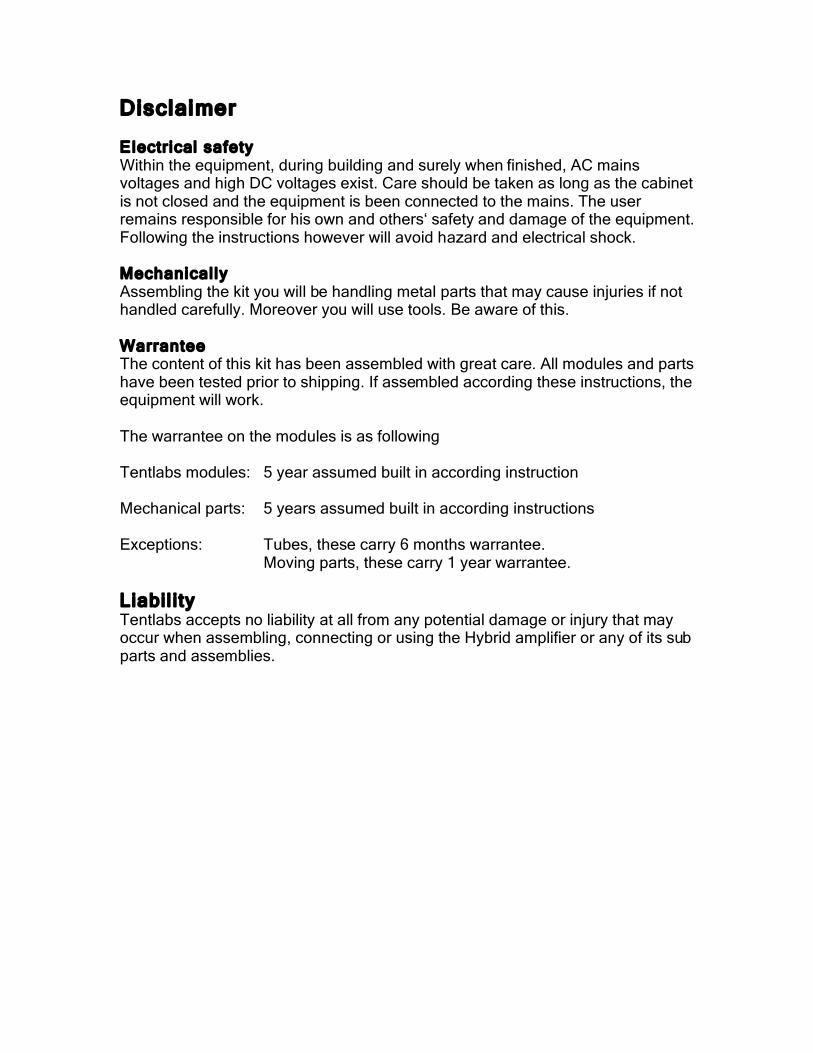
Disclaimer Electrical safety Within the equipment, during building and surely when finished, AC mains voltages and high DC voltages exist. Care should be taken as long as the cabinet is not closed and the equipment is been connected to the mains. The user remains responsible for his own and others‘ safety and damage of the equipment. Following the instructions however will avoid hazard and electrical shock. Mechanical ly Assembling the kit you will be handling metal parts that may cause injuries if not handled carefully. Moreover you will use tools. Be aware of this. Warrantee The content of this kit has been assembled with great care. All modules and parts have been tested prior to shipping. If assembled according these instructions, the equipment will work. The warrantee on the modules is as following Tentlabs modules: 5 year assumed built in according instruction Mechanical parts: 5 years assumed built in according instructions Exceptions: Tubes, these carry 6 months warrantee. Moving parts, these carry 1 year warrantee.
Liabil i ty Tentlabs accepts no liability at all from any potential damage or injury that may occur when assembling, connecting or using the Hybrid amplifier or any of its sub parts and assemblies.
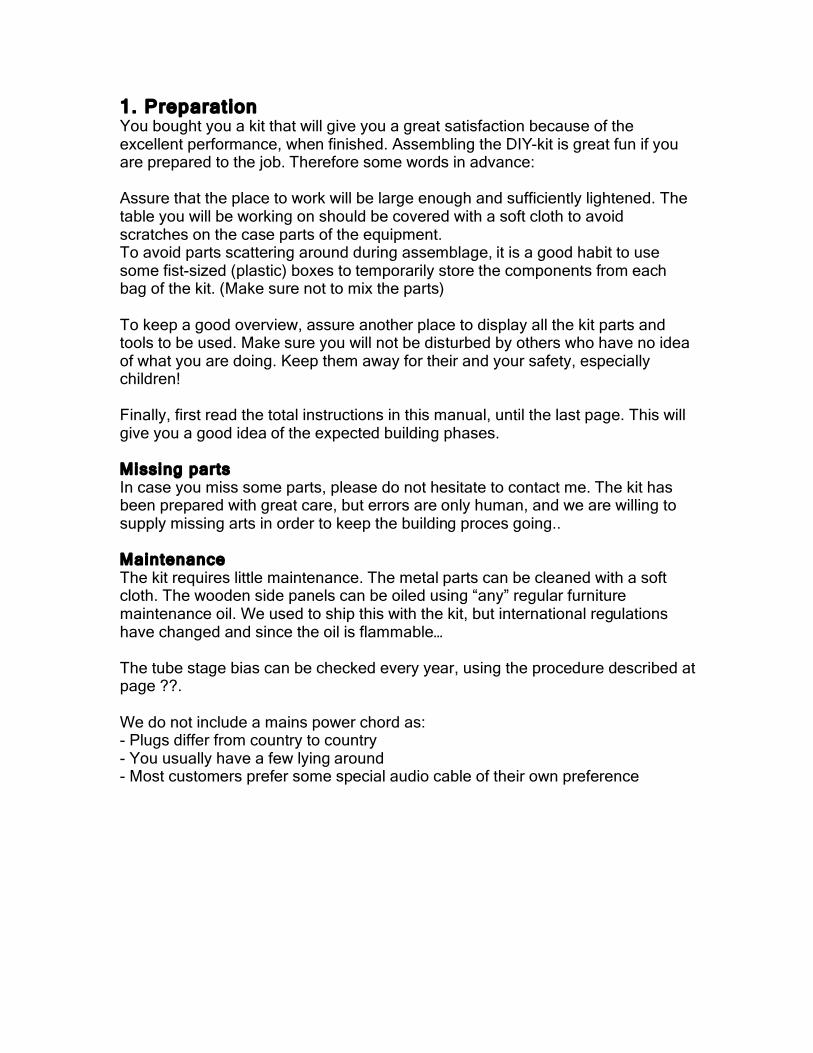
1. Preparat ion You bought you a kit that will give you a great satisfaction because of the excellent performance, when finished. Assembling the DIY-kit is great fun if you are prepared to the job. Therefore some words in advance: Assure that the place to work will be large enough and sufficiently lightened. The table you will be working on should be covered with a soft cloth to avoid scratches on the case parts of the equipment. To avoid parts scattering around during assemblage, it is a good habit to use some fist-sized (plastic) boxes to temporarily store the components from each bag of the kit. (Make sure not to mix the parts) To keep a good overview, assure another place to display all the kit parts and tools to be used. Make sure you will not be disturbed by others who have no idea of what you are doing. Keep them away for their and your safety, especially children! Finally, first read the total instructions in this manual, until the last page. This will give you a good idea of the expected building phases. Missing parts In case you miss some parts, please do not hesitate to contact me. The kit has been prepared with great care, but errors are only human, and we are willing to supply missing arts in order to keep the building proces going.. Maintenance The kit requires little maintenance. The metal parts can be cleaned with a soft cloth. The wooden side panels can be oiled using “any” regular furniture maintenance oil. We used to ship this with the kit, but international regulations have changed and since the oil is flammable… The tube stage bias can be checked every year, using the procedure described at page ??. We do not include a mains power chord as: - Plugs differ from country to country - You usually have a few lying around - Most customers prefer some special audio cable of their own preference
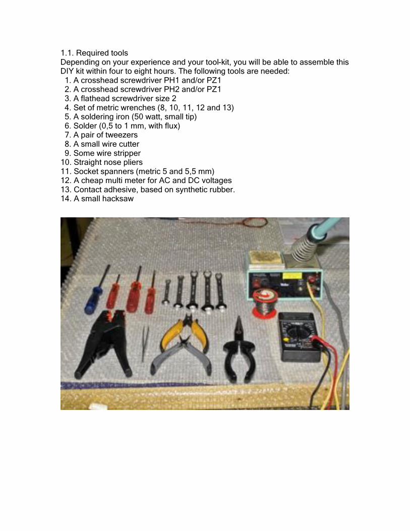
1.1. Required tools Depending on your experience and your tool-kit, you will be able to assemble this DIY kit within four to eight hours. The following tools are needed: 1. A crosshead screwdriver PH1 and/or PZ1 2. A crosshead screwdriver PH2 and/or PZ1 3. A flathead screwdriver size 2 4. Set of metric wrenches (8, 10, 11, 12 and 13) 5. A soldering iron (50 watt, small tip) 6. Solder (0,5 to 1 mm, with flux) 7. A pair of tweezers 8. A small wire cutter 9. Some wire stripper 10. Straight nose pliers 11. Socket spanners (metric 5 and 5,5 mm) 12. A cheap multi meter for AC and DC voltages 13. Contact adhesive, based on synthetic rubber. 14. A small hacksaw
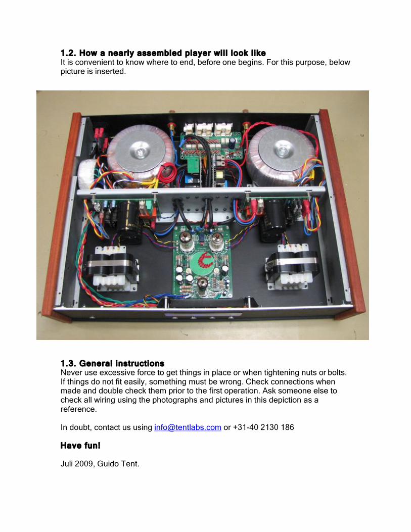
1.2. How a nearly assembled player wi l l look l ike It is convenient to know where to end, before one begins. For this purpose, below picture is inserted.
1.3. General instructions Never use excessive force to get things in place or when tightening nuts or bolts. If things do not fit easily, something must be wrong. Check connections when made and double check them prior to the first operation. Ask someone else to check all wiring using the photographs and pictures in this depiction as a reference. In doubt, contact us using [email protected] or +31-40 2130 186 Have fun! Juli 2009, Guido Tent.

2 Preparing the base Take the base and put it on the table Mount the 4 rubber feet, using 4 pieces M4*8 bolts, al from bag #1. The base plate has threaded holes, hence no nuts are needed. Take both power transformer supports from bag #2 and mount the M6 bolts, nuts and washers from bag #1. Do not forget to put the spring washer between the mount and the nut. Tighten very well, using wrench size ?? Take 8 pieces M4*8 bolts, and mount the supports, from bottom to top. The supports have threaded holes, no nuts required. Tighten well. Take the base, and mount 4 studs (M3*8) using 4 bolts M3*6, all from bag #1, see also next picture. These studs will support the valve driver board.

3 Preparing the bridge This bridge caries the UCD modules, their power supplies and the mains distribution PCB. In addition, the bridge supports the base, once mounted. Take 12 grommets from bag #1 and mount them as shown right. These will support the wiring. Mount 4 studs (M3*6) using 4 bolts M*6, all from bag #1. Please note that the bridge is not symmetrical; take care of correct orientation. The folded edge with the 4 threaded holes should be facing down. Take another 8 studs and M3 bolts and mount them at the opposite side.

3 Mounting the UCD power supply and amplif ier modules Place both modules on top of the studs. The red relays should point inwards. Fix them using 8 pieces M3 nuts. The result should look like this. Mount both UCD modules to the bridge, mirror matched. The result should look like shown right. Use 8 pieces M3*6 bolts. Tighten these well.

4 Wiring the UCD and power supply modules. Take the power and speaker wiring from bag #3. This wiring is all 1.5mm, and is terminated with fast-on connectors. The result of the work on this page looks as shown right. First wire the power leads, fit them through the tules ?? The next photos show the wiring and colors in detail. Use the following colors: “ – “ BLUE “ + “ RED “ gnd “ BLACK Place the wiring on the power supply modules, as shown. The other side of this wiring becomes connected to the UCD modules. Use the same color-coding: “ – “ BLUE “ + “ RED “ gnd “ BLACK Repeat for other channel. This wiring is the most cri t ical part of bui lding this Hybrid ampli f ier. Double check, and have some-one else check the third t ime……… Once that is done, fix the speaker wiring, at the same side of the UCD modules. Use: “ + “ BLUE – left chanel “ + “ RED – r ight channel “ gnd “ BLACK - ground The result should look like shown right

5 Connecting UCD signal wiring Bag #4 contains signal wiring, 2 pieces are assembled with a white connector, one has a blue shrinking sleeve at the other end, one a red sleeve. Make sure these colors coincide with the colors of the speaker wiring, and connect them to the white receptables on the UCD module. Lead the signal wire through the accompanying tule ?? Loosely twist the black and blue wire, and stick them through the remaining tule ?? Repeat this or the other channel, as shown right. Twist the black and red wire. Reverse the bridge. Strip the blue / black wire for about 2mm and connect them as shown right. Use the following connections: “ prot “ = blue “ on “ = black Repeat for other channel. Strip the red / black wire for about 2mm and connect them as shown right. Use the following connections: “ prot “ = red “ on “ = black

6 Connecting the valve PCB signal wiring Take the base, and carefully lay the bridge down, on top of the mounts. This creates some extra space, and facilitates the soldering process. Take the valve driver board from box #8, and put it on the studs. Fix it with 4 pieces M3 nut from bag #1. Take the remaining signal wiring from bag #4. This wiring has a grounded wire (black) at one end. These sides go to the valve driver board. Stick the wiring through the upper middle tule ??, make sure the colors end up at the correct side, as shown on the picture upper right. These wires go to the inputs of the board. Pre-tin the wiring, and connect to “ INL “ according: “ + “ red “ gnd “ black & transparent Repeat for other channel “ INR “. The output wiring, going to the UCD modules, shall be connected to “ OUTL “ respectively “ OUTR “ as following: “ + “ red “ gnd “ black “ – “ transparent The result should look like shown right

7 Mounting the bridge & interstage transformers Take 4 pieces M4*8 bolts, and place the base on its side. You may need the help of a third hand here. Tighten all 4 bolts. Take both interstage transformers from box #9 and #10
WARNING These transformers are wound with 65um wiring, hence very sensitive. Although the wiring is internal, please handle these transformers with care. Cut the wires to 15 cm and twist respectively Purple & yellow Red & blue Solder these wires to the bard, following the indications (P, Y, R, B) Repeat for other channel

8 Mounting interstage transformers Take 8 pieces M4*8 bolts from bag #1, and place the base as shown right. Position the transformers with the wiring pointing towards the bridge. Tighten the 4 bolts and repeat for the other channel Now, most modules have been mounted at the base, and all should look like the picture on the right.
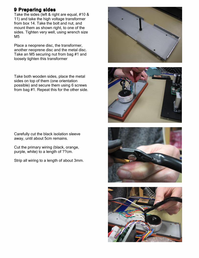
9 Preparing sides Take the sides (left & right are equal, #10 & 11) and take the high voltage transformer from box 14. Take the bolt and nut, and mount them as shown right, to one of the sides. Tighten very well, using wrench size M5 Place a neoprene disc, the transformer, another neoprene disc and the metal disc. Take an M5 securing nut from bag #1 and loosely tighten this transformer Take both wooden sides, place the metal sides on top of them (one orientation possible) and secure them using 6 screws from bag #1. Repeat this for the other side. Carefully cut the black isolation sleeve away, until about 5cm remains. Cut the primary wiring (black, orange, purple, white) to a length of ??cm. Strip all wiring to a length of about 3mm.

10 Preparing the mains PCB Take the mains PCB from bag #5 Place the components as shown right. Diode D1 is sensitive to polarity; make sure the black ring coincides with the mark on the board. Solder all components as shown right, cut the wires from C1 and D1. The result should look like ………… Put it aside, you’ll need it in 10 minutes from now.

11 Preparing the power transformers Take the (heavy) transformers from boxes #13 & #14. The secondary wiring contains fast-on connectors. Twist respectively: Red & yel low Blue & grey Place the transformer besides the base and lead this wiring through the upper grommet Twist the primary wiring as well: Black & red Purple & white?? Repeat this for the other channel. Note to put the secondary wiring through the lower grommet. Connect the secondary winding to the power supply modules. Respect the order as shown right “ ! “ red
“ ! “ grey
“ gnd “ yel low “ gnd “ blue Repeat for the other channel. Note that the modules are mounted mirror-matched; hence the order of colors reverses (from top to bottom): “ gnd “ blue “ gnd “ yel low “ ! “ grey
“ ! “ red
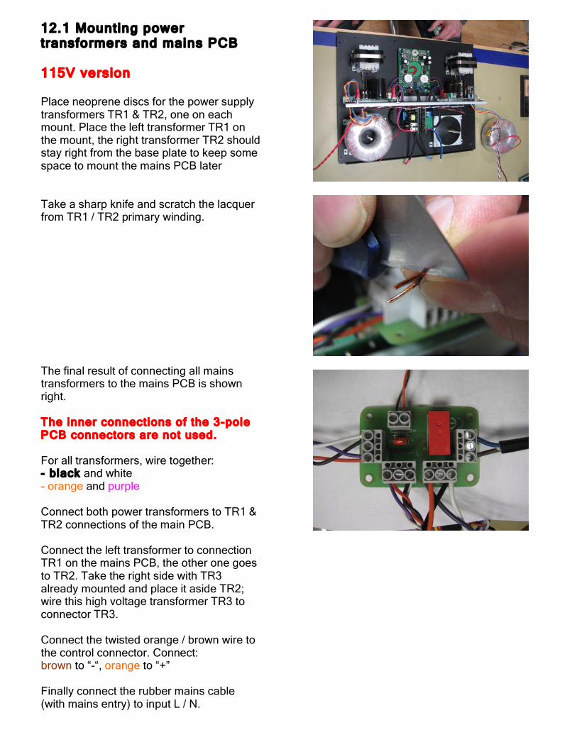
12.1 Mounting power transformers and mains PCB 115V version Place neoprene discs for the power supply transformers TR1 & TR2, one on each mount. Place the left transformer TR1 on the mount, the right transformer TR2 should stay right from the base plate to keep some space to mount the mains PCB later Take a sharp knife and scratch the lacquer from TR1 / TR2 primary winding. The final result of connecting all mains transformers to the mains PCB is shown right. The inner connections of the 3-pole PCB connectors are not used. For all transformers, wire together: - black and white - orange and purple Connect both power transformers to TR1 & TR2 connections of the main PCB. Connect the left transformer to connection TR1 on the mains PCB, the other one goes to TR2. Take the right side with TR3 already mounted and place it aside TR2; wire this high voltage transformer TR3 to connector TR3. Connect the twisted orange / brown wire to the control connector. Connect: brown to “-“, orange to “+” Finally connect the rubber mains cable (with mains entry) to input L / N.

12.2 Mounting power transformers and mains PCB 230V version Place neoprene discs for the power supply transformers TR1 & TR2, one on each mount. Place the left transformer TR1 on the mount, the right transformer TR2 should stay right from the base plate to keep some space to mount the mains PCB later Take a sharp knife and scratch the lacquer from TR1 / TR2 primary winding. The final result of connecting all mains transformers to the mains PCB is shown right. For all transformers, wire together to the middle connection of the PCB connectors: orange and white Black and purple go to the remaining outer connections Connect the power transformers to TR1 & TR2 connections of the main PCB, the left transformer to connection TR1 on the mains PCB, the other one goes to TR2. Take the right side (with TR3 already mounted) and place it besides the chassis. Connect TR3 to connector TR3. Connect the twisted orange / brown wire to the control connector. Connect: brown to “-“, orange to “+” Finally connect the rubber mains cable (with mains entry) to input L / N
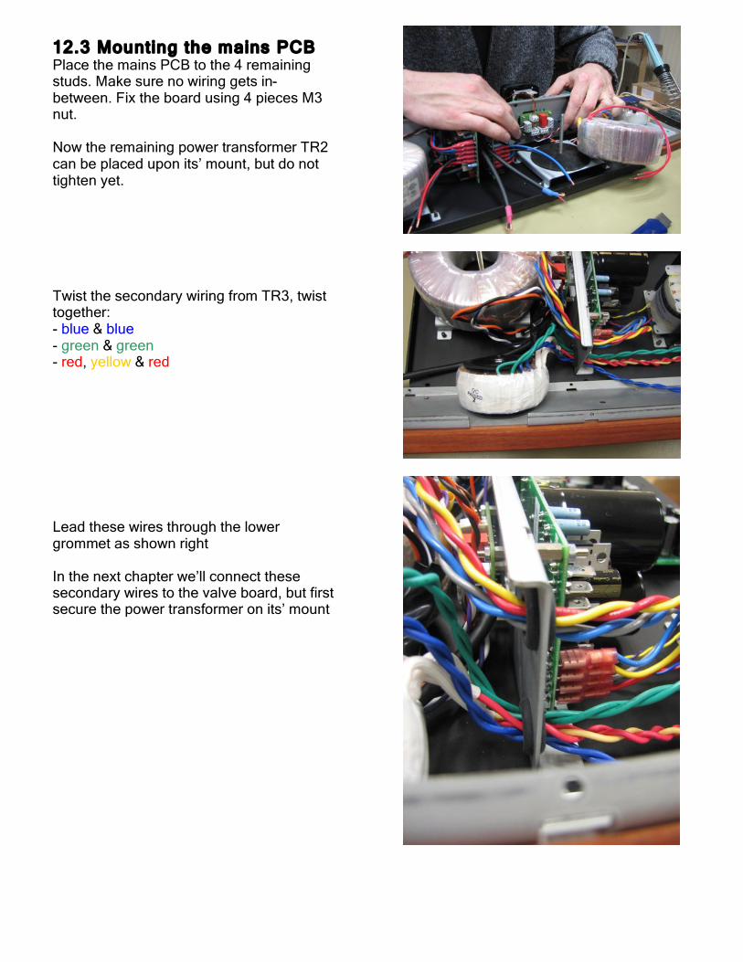
12.3 Mounting the mains PCB Place the mains PCB to the 4 remaining studs. Make sure no wiring gets in-between. Fix the board using 4 pieces M3 nut. Now the remaining power transformer TR2 can be placed upon its’ mount, but do not tighten yet. Twist the secondary wiring from TR3, twist together: - blue & blue - green & green - red, yellow & red Lead these wires through the lower grommet as shown right In the next chapter we’ll connect these secondary wires to the valve board, but first secure the power transformer on its’ mount
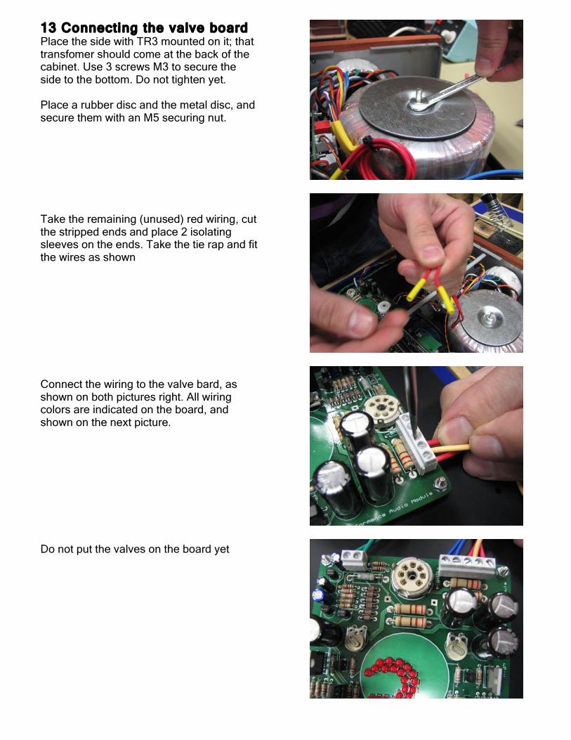
13 Connecting the valve board Place the side with TR3 mounted on it; that transfomer should come at the back of the cabinet. Use 3 screws M3 to secure the side to the bottom. Do not tighten yet. Place a rubber disc and the metal disc, and secure them with an M5 securing nut. Take the remaining (unused) red wiring, cut the stripped ends and place 2 isolating sleeves on the ends. Take the tie rap and fit the wires as shown Connect the wiring to the valve bard, as shown on both pictures right. All wiring colors are indicated on the board, and shown on the next picture. Do not put the valves on the board yet

14 Preparing the volume control module Take box # 6 and a small hacksaw. Separate the volume control board into 2 modules, the front and the main PCB. Carefully separate the 2 boards, do not use excessive force. Flattn the cut boards, using an appropriate file. Take the 5 pole colored wire (black to yellow) and put it through the middle grommet (the lowest). The connector should be at the back of the amplifier, the loose ends go below the valve driver board to the front. Take the brown / orange wiring from the bag #5, lead it through the closest lower grommet towards the valve board, and back towards the back through the middle lower grommet, the same carrying the 5 pole wiring. Lead it to the back in-between both UCD modules.

15 Assembling the back Take 3 screws from bag #1 and mount the volume control input board to the back of the amplifier. Take the speaker terminals, take them apart and mount them at the back. Look how the side entries are locatd, this should be done as shown right, to facilitate wiring entering the connectors.

16 Connecting volume control Pre tin the signal wiring that is going to be soldered to the vlume control main board. This detail shows how to connect this signal wiring; Red = + White = - Connect both red wires from the mains transformer to the volume control bard as shown. Repeat the same for the orange / brown wiring, from the mains PCB, to “rel”. Connect brown to “-“, orange to “+”. Stick colred wiring with its’ connector to the socket on the volume control board.

17 Connecting earth tag Take the mains entry, and click it into the back panel (switch up). Take the safety earth wire and put it on the M4 screw from the transformer-mounting bracket. Take an M4 securing washer, and an M4 nut, and fix the tag. Tighten firmly.

18 Connecting speaker wires Strip the ends of the loudspeaker terminal wiring, 10mm will do. Twist the copper wiring, and double fold it. Fit each wire in the loudspeaker terminal, tighten firmly. Black goes to black The red and blue wires go the red terminals, depending on the channel. It may help to release the volume control board from the back, temporarily. Once these 4 connections are OK, the back panel can be secured to the amplifier; use 7 pieces M3*6 screw (securing process not shown on photo).

19 Assembling the f ront Place the front panel and front sub panel as shown. Clean both surfaces using white spirit, or another suitable cleaner Put sufficient dots of suitable glue all over the surface. Bring the 2 panels together. Make sure the panels are well aligned. The front switch holes are a suitable point to focus on; these holes shall be well centered as shown right.
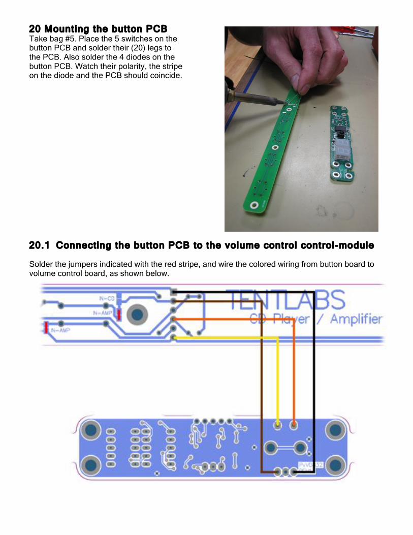
20.1 Connecting the button PCB to the volume control control-module Solder the jumpers indicated with the red stripe, and wire the colored wiring from button board to volume control board, as shown below.
20 Mount ing the button PCB Take bag #5. Place the 5 switches on the button PCB and solder their (20) legs to the PCB. Also solder the 4 diodes on the button PCB. Watch their polarity, the stripe on the diode and the PCB should coincide.

21 Preparing the front Place the 5 buttons. On the same row, 5 studs are present. Place M3 nuts on these studs, so that about 3mm of thread remains. Place the button PCB on top Adjust all 5 nuts so that the buttons “just” touch the switches. Secure the button PCB using another 5 pieces of M3 nuts. Keep checking if the button to switch distance is OK.

21.1 Finishing the front panel Place the blue acrylic. They should gently snap into its place. Do not remove protective foils yet ! Take the Display cover and mount 4 studs, using M3*6 screws. Note An error has been made in production. Use the inner 4 holes, of which 2 of them are made by hand. Place the front panel PC on the Display cover, and secure it with 4 M3 nuts.

22 Wir ing the front PCB Take the coloured wiring (5 colours) from the volume control relay board, the white connector can be released. Solder the 5 coloured wires to the front panel PCB, as shown right. Place the new assembly on the 4 remaining studs on the front panel assembly Fix the Display cover using 4 pieces M3*6 screw.

22.1 Placing the front panel Mount the front panel support on the 2 studs, use 2 pieces M3 nut. Now the front panel is fully prepared, it can be mounted in the cabinet. Release the screws that connect the base plate with the sides, a little. Place the front panel and secure it with 4 nuts M3 Guide the interface cable from the volume control below the valve driver board, through the central bridge (middle grommet) towards the relays board: Connect using the white connector. The moment of truth is coming nearer… Ask a friend or neighbor to carefully check all wiring. Fatal damage may occur when errors are made in: • Transformer to supply module wiring • Power supply to UCD module wiring • Transformer to valve driver module
wiring So give these points extra attention when checkng

23 Switching on amplif ier / Adjust ing the valve driver bias Place the tubes on their holders on the board. Gently wiggle them, while pushing downards. After careful checkup, the amplifier can be switched on. Normally after about 15 seconds the valves and the LED logo will light up. Let the amp stabilize for 10 minutes, than the adjustment can be carried out. On the driver module, 2 potentiometers are present. These adjust the standing current through the shunt regulator. These are factory adjusted, but may need some fine-tuning. Take a screwdriver that neatly fits in the black trimming potentiometers. Connect the black probe of a multimeter (range 200mV DC) with the speaker ground (either channel OK), and the red probe on the points indicated on the drawing below (red for left channel, blue for right). Trim the trimmer until the multimeter reads 60mV (+/- 6mV). Repeat for other channel.

http://www.tentlabs.c
24 Congratulat ions ! Enjoy the glow, and the sound !