Assembly Instructions DucoSlide Luxframe 40/80 Linear 115
14
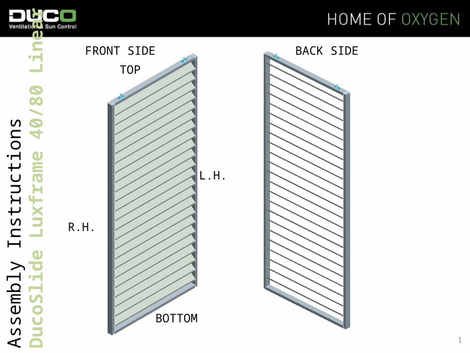
Assembly Instructions DucoSlide Luxframe 40/80 Linear TOP BOTTOM L.H. R.H. FRONT SIDE BACK SIDE 1
-
Upload
willoughby-roland -
Category
Documents
-
view
37 -
download
3
description
FRONT SIDE. BACK SIDE. TOP. Assembly Instructions DucoSlide Luxframe 40/80 Linear 115. L.H. R.H. BOTTOM. Parts Breakdown. Parts Breakdown. Parts List All cut lengths of the individual parts are specified in the parts list. - PowerPoint PPT Presentation
Transcript of Assembly Instructions DucoSlide Luxframe 40/80 Linear 115
Asse
mbl
y In
stru
ction
s D
ucoS
lide
Luxf
ram
e 40
/80
Line
ar 1
15 TOP
BOTTOM
L.H.
R.H.
FRONT SIDE BACK SIDE
1

19-04-2023 2

19-04-2023 3

Lux 40/80 series top and bottom rails
Code : P1402710
Cut dimension = frame width - 80 mm
Linear 115 series louvre blade
Code : P1403610
Cut dimension = frame width - 80 mm
Lux 40/80 series (LH/RH) stile
Code : P1403110
Cut dimension = frame height - 6 mm
Lux 40/80 series cover plate
Code : G0100521
Lux 40/80 series stile cover trim
Code : P1401510
Cut dimension = frame width - 80 mm
Thread-forming screw :DIN 7500 Form C, M6 x 30, A2 stainless steelPan head with PZ 3 drive
Code : G0100525
(Needed for fixing the frame and the blades)
Parts Breakdown
19-04-2023 4

Thread-forming screw :DIN 7500 Form C, M4 x 20, A2 stainless steelCountersunk head with PZ 2 drive
Code : G0100526
(Needed for fixing the cover plates.)
Bottom guide base Ø 25 mm
Code : G0013003
Top rail suspension bracket 34/40/3
Code : G0013031
Self-drilling screw :DIN 7504 Form O, M3.9 x 19, A2 stainless steelCountersunk head with PH 2 drive
Code : G0100528
(Needed for fixing the bottom guide foot)
Self-drilling screw :DIN 7500 Form M, M4.8 x 16, A2 stainless steelPan head with PH 2 drive
Code : G0000227
(Needed for fixing the suspension bracket)
Top rail suspension bracket31/33/2
Code: G0013080
Parts Breakdown
19-04-2023 5
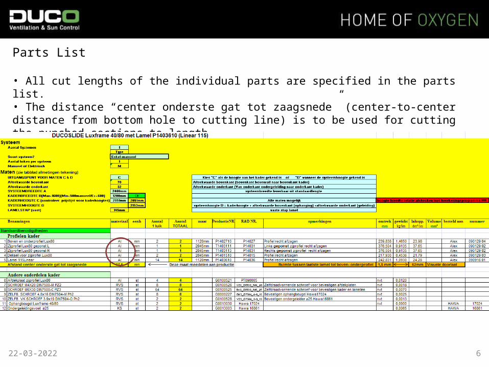
Parts List
• All cut lengths of the individual parts are specified in the parts list.• The distance “center onderste gat tot zaagsnede” (center-to-center distance from bottom hole to cutting line) is to be used for cutting the punched sections to length.This distance should be passed to the production department.
19-04-2023 6

MOUNTING SEQUENCE
1. Sizing
* Cut both the top rail and the bottom rail off square : length = slide width - 80 mm (twice the width of the stile).* Cut the blades to the same length as the top and bottom rail.* Cut a LH and a RH vertical pre-punched profile down to size taking into account the symmetric distribution of the hole pattern : length = slide width – 6 mm (twice the width of the cover plate. Since the cover cap is not cut at the same time as the vertical profile, a - 0.5 mm up to - 1 mm tolerance on the length of the vertical profile needs to be taken into account to make sure the cover cap can be retrofitted.
19-04-2023 7

2. Mounting Preparations
* Using the drilling jig, drill 6.2 mm holes in the top and bottom of the vertical profiles. Make sure the drilling jig is a tight fit against the extreme end of the vertical profiles and hold it in position using a quick action clamp or an F-clamp.
19-04-2023 8

3. Fitting the Slide Make sure to use the correct screw bit for each type of screw drive (PH 2, Pz 2, PZ 3) and adjust the tightening torque of the drill/screwdriver to the screws involved.
* Fit a cover plate to either end of the vertical profiles using two A2 stainless steel M4 x 20 DIN 7500 Form M screws with PZ 2 drive.
* Slide the top and bottom rail, with the visible drill groove facing outwards, in between the vertical profiles and secure them on one side using A2 stainless steel M6 x 25 DIN 7500 Form C screws with PZ 3 drive for each rail. For the other vertical profile, screw the screws a few turns leaving enough room for the blades to be a sliding fit.
* Place the blades in the positioning jig and make sure both front and back of the blades lie flush with the stile first and then fix each in place on one side using two A2 stainless steel M6 x 25 DIN 7500 Form C screws with PZ 3 drive. On the opposite side, tighten each screw by only a few turns.19-04-2023 9

* Now push the remaining vertical profile fully home against the already assembled items. Firmly tighten the screws of the top and bottom rail first and then those securing the blades.
* Check the slide for squareness by taking measurements across the diagonals using a tape measure.
* Where appropriate, make sure you have the slide flat on a tabletop if it does not fit flat against (tilted to one side) this work surface.
* Fit the cover caps to the vertical profiles.
That's how the positioning jiglooks like.
19-04-2023 10

4. Fittings Mounting
* Place the suspension bracket (G0013031 or G0013080) on the top rail of the slide using the positioning jig. Be sure the hole provided in the suspension bracket, to accommodate the suspension bracket screw, points towards the rear of the slide. Fasten it with four A2 stainless steel M 4.8 x 18 DIN 7504-M self-drilling screws with PH 2 drive. Do this for both sides of the slide.
* A choice of three possible fixing positions of the suspension bracket (G0013031 or
G0013080) is available :These positions vary depending upon what the customer ordered !1) Standard position at 150 mm for all slides ; 2) At 195 mm for telescopic and symmetric slides on the return pulley side ; 3) At 260 mm for the side of the slide underneath the actuator, of all electric
motorized slides. These different positions can be set by shifting of removing the pin, depending on the position by the suspension bracket.
19-04-2023 11
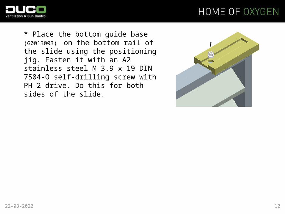
* Place the bottom guide base (G0013003) on the bottom rail of the slide using the positioning jig. Fasten it with an A2 stainless steel M 3.9 x 19 DIN 7504-O self-drilling screw with PH 2 drive. Do this for both sides of the slide.
19-04-2023 12
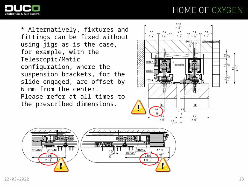
* Alternatively, fixtures and fittings can be fixed without using jigs as is the case, for example, with the Telescopic/Matic configuration, where the suspension brackets, for the slide engaged, are offset by 6 mm from the center. Please refer at all times to the prescribed dimensions.
19-04-2023 13

Put the CE-label on a visible spot, for example on the side of the frame (do not put it on the blades)
Make sure the label fits good on the frame.
14
CE label