ASSEMBLY AND OPERATION MANUAL - Hobbicomanuals.hobbico.com/dtx/dtxc0064-manual.pdf · truck...
20
TM Warranty • DuraTrax ® will warranty this kit for 90 days after the purchase date from defects in materials or workmanship. DuraTrax will either repair or replace, at no charge, the incorrectly made part. • Make sure you save the receipt or invoice you were given when you bought your model! It is your proof of purchase and we must see it before we can honor the warranty. • To return your Maximum MT for repairs covered under warranty you should send your truck to: Hobby Services 1610 Interstate Drive Champaign, Illinois 61822 Attn: Service Department Phone: (217) 398-0007 9:00 am - 5:00 pm Central Time M-F E-mail: [email protected] Before Building: We want the building and operating of this vehicle to be a success, so BEFORE removing any parts from the parts bags please read this manual thoroughly and watch the included video to familiarize yourself with the model. If for any reason you think this model is not for you, return it to your dealer immediately. PLEASE NOTE: Your hobby dealer cannot accept a return on any model after assembly has begun. ASSEMBLY AND OPERATION MANUAL © Copyright 1999 Printed in USA DTXZ1052 For Kit DTXC0064/DTXD64**
Transcript of ASSEMBLY AND OPERATION MANUAL - Hobbicomanuals.hobbico.com/dtx/dtxc0064-manual.pdf · truck...
TM
Warranty• DuraTrax® will warranty this kit for 90 days after the purchase date from defects in materials or workmanship. DuraTrax
will either repair or replace, at no charge, the incorrectly made part.• Make sure you save the receipt or invoice you were given when you bought your model! It is your proof of purchase
and we must see it before we can honor the warranty. • To return your Maximum MT for repairs covered under warranty you should send your truck to:
Hobby Services1610 Interstate Drive
Champaign, Illinois 61822Attn: Service Department
Phone: (217) 398-0007 9:00 am - 5:00 pm Central Time M-FE-mail: [email protected]
Before Building:We want the building and operating of this vehicle to be a success, so BEFORE removing any parts from the parts bagsplease read this manual thoroughly and watch the included video to familiarize yourself with the model. If for any reasonyou think this model is not for you, return it to your dealer immediately. PLEASE NOTE: Your hobby dealer cannot accepta return on any model after assembly has begun.
ASSEMBLY AND OPERATION MANUAL
© Copyright 1999 Printed in USA DTXZ1052 For Kit DTXC0064/DTXD64**

Introduction.................................................................................2Safety Precautions .....................................................................2Helpful Hints................................................................................2Stress-Tech™ Parts Guarantee...................................................2Repair Service.............................................................................2Specification & Description Changes.......................................3Screw Information ......................................................................3Required Items for Completion .................................................3Tools You Will Need....................................................................3Finishing the RTR Version.........................................................4Assembly of the Pre-Built Version............................................7Preparing the Radio System......................................................7Steering Servo Assembly ..........................................................7Assembling the Radio Tray .......................................................8Installing the Throttle Servo ....................................................10Throttle & Brake Linkages .......................................................10Radio Adjustments ...................................................................11Prepare the Engine...................................................................12Finishing....................................................................................13Carburetor Settings ..................................................................14Breaking-In the Engine ............................................................15Running the Engine..................................................................15Engine Maintenance .................................................................16Performance Tuning .................................................................17Maintenance Tips......................................................................18Engine Trouble Shooting .........................................................19
Thank you for purchasing the DuraTrax Maximum MT. Thismanual contains the instructions you need to build, operate,and maintain your new nitro R/C truck. Read over this manualthoroughly before building or operating the Maximum MT.
When the safety precautions are followed, the Maximum MTwill provide years of enjoyment. Use care and good senseat all times when operating this radio controlled truck.Failure to use this vehicle in a safe, sensible manner canresult in injury or damage to property. You and you alonemust insure that the instructions are carefully followed andall safety precautions are obeyed.
• Do not operate the Maximum MT near people. Spectatorsshould be behind the driver or at a safe distance awayfrom the vehicle.
• The engine and exhaust system produces quite a bit ofnoise. If you are disturbed by the amount of noise thistruck produces, wear ear protection such as earplugs.Do not run this vehicle when or where it can disturb others.
• The engine and exhaust system can become very hot.Avoid touching any of these parts during use and untilthey have cooled down.
• Model engine fuel is poisonous. Make sure you read andfollow all of the precautions on the fuel container. Keepfuel out of the reach of children.
• Model engine fuel is flammable and when ignited has aflame that is difficult to see. Avoid sparks, flames,smoking, or any other ignition source when fuel is near.
• The engine emits carbon dioxide just like real cars. Donot operate this model indoors.
• Before turning on the transmitter, make sure that no oneelse is on your frequency.
• Avoid working over a deep pile carpet. If you drop a smallpart or screw, it will be difficult to find.
• Place a mat or towel over your work surface. This willprevent parts from rolling off and will protect the work surface.
• Avoid running the truck in cold weather. The plastic andmetal parts can become brittle at low temperatures. Inaddition, grease and oil become thick, causing prematurewear and poor performance.
• Test fit all parts before attaching them permanently.
We have engineered the Maximum MT to take the roughand tumble abuse that makes R/C fun. We are so confidentof the quality and durability of the Stress-Tech™ plastic partsthat we will replace any Stress-Tech plastic part you breakduring the first 6 months you own the truck. Just send in thepart to us and we will send you a Free replacement. Pleasesee the Maximum MT parts list for the items covered underthe Stress-Tech guarantee.
To receive your free replacement part please send thefollowing to the Hobby Services address listed on the coverof this manual:
• The broken part must be included.• The part number and description of the broken part.• Dated copy of your invoice or purchase receipt.• Your name, phone number and shipping address.
Repair service is available anytime. • After the 90 day warranty, you can still have your
Maximum MT repaired for a small charge by the expertsat DuraTrax’s authorized repair facility, Hobby Services,at the address listed on the cover of this manual.
REPAIR SERVICE
STRESS-TECH™ PARTS GUARANTEE
HELPFUL HINTS
SAFETY PRECAUTIONS
INTRODUCTION
TABLE OF CONTENTS
2

To speed up the repair process, please follow the instructionslisted below.
1. Under most circumstances return the ENTIRE system: truckand radio. The exception would be sending in a Stress-Techpart. See the instructions under the Stress-Tech Guarantee.
2. Make sure the transmitter is turned off, all batteries areremoved, and fuel is drained from the tank.
3. Send written instructions which include: a list of all itemsreturned, a THOROUGH explanation of the problem andthe service needed, and your phone number during theday. If you expect the repair to be covered underwarranty, be sure to include a proof of date of purchase(your store receipt or purchase invoice).
4. Also be sure to include your full return address.
All pictures, descriptions, and specifications found in thisinstruction manual are subject to change without notice.DuraTrax maintains no responsibility for inadvertent errorsin this manual.
Do not use too much force when tightening self-tappingscrews into plastic. Overtightening will cause the threads inthe plastic to strip. We recommend that you stop turning aself-tapping screw when you feel some resistance as thehead of the screw comes in contact with the plastic. Avoidusing powered screwdrivers when assembling this kit. Theytend to overtighten the screws. Do not use thread lockingcompound on any self-tapping screws. The thread lockingcompound may damage the plastic. IMPORTANT: Usethread lock on any fastener that is threaded into metal orfastened with a nut. Vibration from the engine will cause thescrews to loosen if thread locking compound is not used.
The illustration above shows how to identify the types ofscrews used throughout this instruction manual.
To operate the Maximum MT these items are required:
• Glow plug starter (Hobbico® Hot-Shot™ 2 -HCAP2520)• Fuel bottle (DuraTrax Kwik-Pit™ Bottle - DTXP0125)• Fuel (DuraTrax Red Alert™ fuel - DTXP0520)• Air filter oil• Tie straps• Hobby knife with #11 blade (HCAR0105)• Glow plug wrench (DTXR1170) • It is also helpful to have a couple of extra glow plugs
on hand. We recommend the O.S®. #A3 plug (OSMG2690)
(All of these items are available in a Nitro Starter Packfrom DuraTrax - DTXP0200).
For the Pre-Built version of the Maximum MT, you will alsoneed:
• 2-channel radio with (2) standard servos• (12) “AA” batteries - (4) for the receiver and (8) for the
transmitter• Small bottle of thread locking compound (GPMR6060)
To assemble the Pre-Built version (DTXC0055), you willneed the following tools:
• Phillips head screwdriver• Flat blade screwdriver• Needle-nose pliers• Wire cutters�• Hobby knife (HCAR0105), #11 blades (HCAR0211)• Drill with 1/4", 1/8", 5/64" (or 6mm, 3mm, 2mm) bits
TOOLS YOU WILL NEED
REQUIRED ITEMS FOR COMPLETION
3mm
14mm
M3x14 Screw
3mm
14mm
M3x14Self-Tapping
Screw
SCREW INFORMATION
SPECIFICATION & DESCRIPTION CHANGES
3

❏ 1. Remove the transmitter and truck from the box.
❏ 2. Remove the twist-tie from the receiver antenna. (Thereceiver antenna looks like a bundled thin wire that isattached to the receiver.) Thread the receiver antennaunderneath and through the hole in the radio plate next tothe receiver switch.
❏ 3. Remove the antenna tube from the parts bag. Threadthe receiver antenna through the antenna tube. The antennawill be longer than the antenna tube. DO NOT COIL OR CUTTHE ANTENNA. Press fit the antenna tube through the holein the radio plate. Place a 1/8" long piece of fuel tubing overthe antenna tube and wire to secure in place. TIP: Run theantenna through your fingers to straighten out kinks beforerunning through the antenna tube.
❏ 4. Remove the air filter and tie strap from the parts bag.Thoroughly soak the air filter foam with some oil (notincluded) and then squeeze out the excess oil. A light machineoil (like 3-IN-ONE™) will work well. Special oils made for airfilters are also available in most hobby and motorcycleshops. Place the air filter onto the carburetor and secure itin place with the tie strap. Cut off the excess part of thestrap.
❏ 5. Remove the four screws from the top of the radio plateand remove the receiver battery holder.
4
FINISHING THE RTR VERSION (DTXD64**)

❏ 6. Remove the receiver battery holder from the radio box.Install (4) “AA” (included) into the battery holder in theconfiguration molded into the battery holder.
❏ 7. Re-install the receiver battery holder under the radioplate. Make sure that the receiver switch is in the offposition. Plug the connector on the receiver battery into thesocket on the receiver switch. Tuck the wires between theservo and receiver battery so they will not get caught onanything.
❏ 8. Remove the transmitter antenna from the holder andscrew it into the hole on top of the transmitter.
❏ 9. Slide open the battery door on the bottom of thetransmitter and remove the transmitter battery holder. Place8 “AA” batteries into the holder in the configuration moldedinto the plastic on the battery holder. Re-install thetransmitter battery holder into the transmitter and re-installthe battery door.
❏ 10. Turn on the transmitter using the switch on the back(see the photo with Step 8), The green light on the side ofthe transmitter should light up. If there is no light on, turn thetransmitter off and check to ensure that the battery holder ismaking contact with the copper contacts on the inside of thebattery compartment. Make sure the batteries are installedcorrectly. Turn the transmitter on and check for the greenindicator light. If the green light appears, turn off thetransmitter.
❏ 11. Remove the plastic from the outside of the body.Apply the decals if desired. For decal placement, see thephotos on the box top.
5

❏ 12. Assemble the rollbar as shown using ten 2.6 x 6mmself-tapping screws.
❏ 13. Drill six 1/4" (6mm) holes in the body using themolded-in dimples as guides. Install the rollbar onto body asshown using six 2.6 x 6mm self-tapping screws and theincluded collars.
❏ 14. Drill two 1/4" (6mm) holes in front of body using themolded-in dimples as guides. Install the front brush guardas shown with two 2.6 x 6mm self-tapping screws and thecollars included.
❏ 15. Drill one 1/8" (3mm) hole in each side of the bodyusing the molded-in dimple as a guide, and one 5/64"(2mm) hole 7/16" (11mm) below and 7/16" back from firsthole (use the pegs on the mirror as a guide). Install themirrors as shown with the collars provided.
❏16. Remove the body clips from the parts bag. Place the bodyon the body mounts. On each body mount place a body clip.
Congratulations, you have completed preparations!Before running your new truck, please take the time tocarefully read the instructions and watch the video beforerunning and breaking-in the engine. Make sure you followthe safety precautions and most of all...HAVE FUN!
6
7
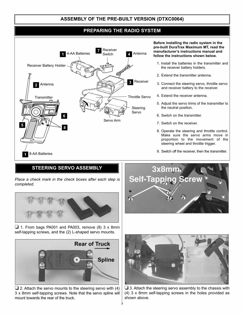
1. Install the batteries in the transmitter andthe receiver battery holders.
2. Extend the transmitter antenna.
3. Connect the steering servo, throttle servoand receiver battery to the receiver.
4. Extend the receiver antenna.
5. Adjust the servo trims of the transmitter tothe neutral position.
6. Switch on the transmitter.
7. Switch on the receiver.
8. Operate the steering and throttle control.Make sure the servo arms move in proportion to the movement of the steering wheel and throttle trigger.
9. Switch off the receiver, then the transmitter.
Before installing the radio system in thepre-built DuraTrax Maximum MT, read themanufacturer’s instructions manual andfollow the instructions shown below.
Servo Arm
SteeringServo
Throttle Servo
Receiver Battery Holder
4-AA Batteries
Transmitter
5
6
1 Antenna4
8-AA Batteries1
Receiver3
ReceiverSwitch
7
Antenna2
8
PREPARING THE RADIO SYSTEM
ASSEMBLY OF THE PRE-BUILT VERSION (DTXC0064)
Place a check mark in the check boxes after each step iscompleted.
❏ 1. From bags PA001 and PA003, remove (8) 3 x 8mmself-tapping screws, and the (2) L-shaped servo mounts.
❏ 2. Attach the servo mounts to the steering servo with (4)3 x 8mm self-tapping screws. Note that the servo spline willmount towards the rear of the truck.
❏ 3. Attach the steering servo assembly to the chassis with(4) 3 x 8mm self-tapping screws in the holes provided asshown above.
STEERING SERVO ASSEMBLY

❏ 4. From bag PA001, remove the steering rod. Note theshape of the rod.
❏ 5. Use a 3 or 4 hole servo arm from your radio system. A1, 2, or 4-armed servo arm will work. Cut off all but one ofthe arms by scoring both sides of the servo arm with ahobby knife and using pliers to snap off the arm.
❏ 6. Put the steering rod into the third hole from the centerof the servo arm (approximately 5/8" or 16mm). You mayneed to enlarge the hole in the servo arm with a 5/64"(2mm) drill or a hobby knife.
❏ 7. Place the rod connector through the top of the middlehole in the steering arm. Place a small amount of threadlocking compound onto the threads of the rod connector.Do not to overtighten the nut, the rod connector mustswivel freely. Install the 2mm nut onto the bottom of the rod
connector. Install a 2mm set screw into the top of the rodconnector. Note: When installing the set screw, make surenot to thread it in too far because the steering rod must passthrough the hole on the side of the rod connector.
❏ 8. Slip the steering rod through the hole in the rodconnector that is already installed on the servo saver. (Usethe screw that came with your radio system to attach theservo arm to the steering servo.) Do not tighten the setscrew on the rod connector. You will make the steeringadjustments later.
❏ 1. From bag PA002, remove all of the parts included; theradio tray, the (2) radio tray mounts, and the (8) 3 x 8mmself-tapping screws.
❏ 2. Place foam tape on the bottom of the radio plate. Thiswill secure the receiver battery into place when the radioplate is installed.
ASSEMBLING THE RADIO TRAY
8
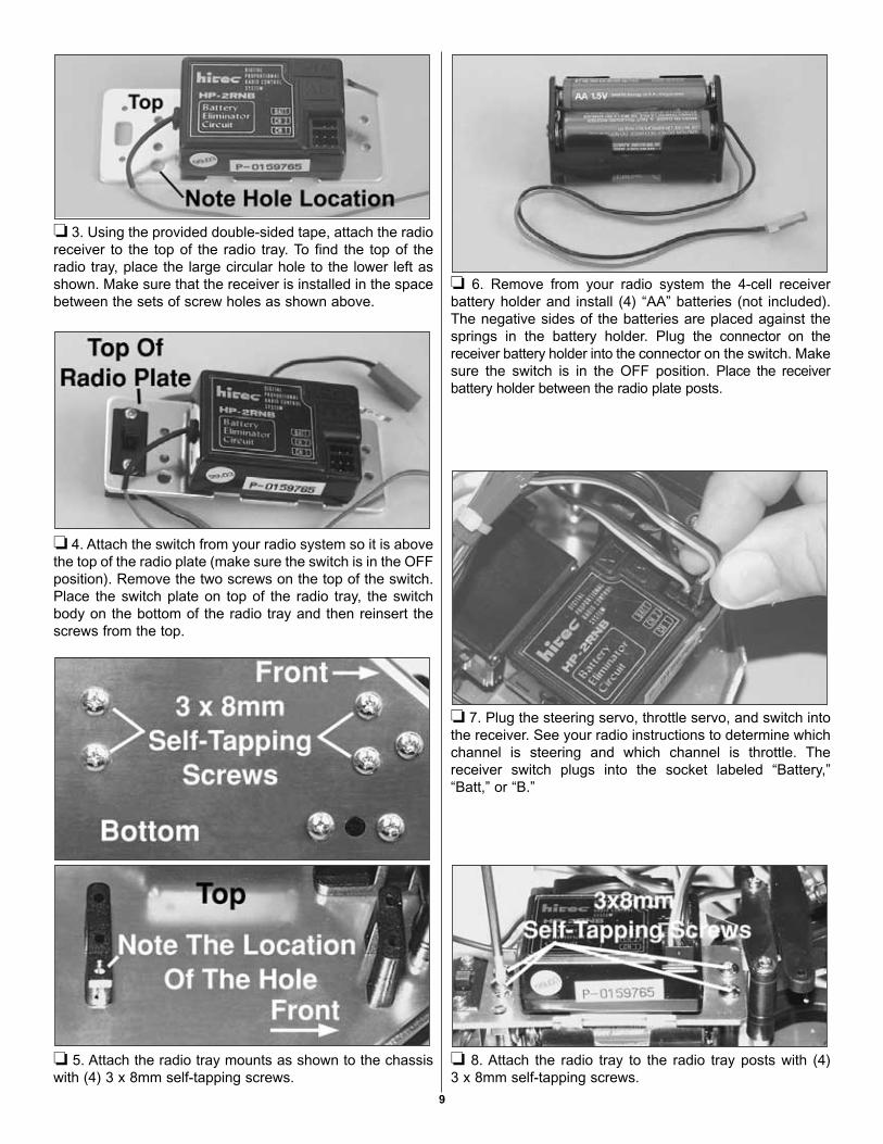
❏ 3. Using the provided double-sided tape, attach the radioreceiver to the top of the radio tray. To find the top of theradio tray, place the large circular hole to the lower left asshown. Make sure that the receiver is installed in the spacebetween the sets of screw holes as shown above.
❏ 4. Attach the switch from your radio system so it is abovethe top of the radio plate (make sure the switch is in the OFFposition). Remove the two screws on the top of the switch.Place the switch plate on top of the radio tray, the switchbody on the bottom of the radio tray and then reinsert thescrews from the top.
❏ 5. Attach the radio tray mounts as shown to the chassiswith (4) 3 x 8mm self-tapping screws.
❏ 6. Remove from your radio system the 4-cell receiverbattery holder and install (4) “AA” batteries (not included).The negative sides of the batteries are placed against thesprings in the battery holder. Plug the connector on thereceiver battery holder into the connector on the switch. Makesure the switch is in the OFF position. Place the receiverbattery holder between the radio plate posts.
❏ 7. Plug the steering servo, throttle servo, and switch intothe receiver. See your radio instructions to determine whichchannel is steering and which channel is throttle. Thereceiver switch plugs into the socket labeled “Battery,”“Batt,” or “B.”
❏ 8. Attach the radio tray to the radio tray posts with (4) 3 x 8mm self-tapping screws.
9

❏ 9. Fit the antenna tube through the radio tray and pressfit the antenna tube into the radio tray post. Thread thereceiver antenna through the antenna tube. The receiverantenna wire will be longer than the antenna tube. DO NOTCUT OR COIL THE ANTENNA. Use tape or cut 1/4" longpieces of fuel tubing to attach the leftover antenna wire to theoutside of the antenna tube. Use a hobby knife or drill to cuta hole in the body to route the antenna tube through.
❏ 1. From bags PA001 and PA003, remove the (2) throttleservo mounts and (8) 3 x 8mm self-tapping screws.
❏ 2. Use the (4) 3 x 8mm self-tapping screws to attach thethrottle servo to the throttle servo mounts.
❏ 3. Use the (4) 3 x 8mm self-tapping screws to attach thethrottle servo and the mounts to the chassis. Make sure thatthe servo spline is towards the rear.
❏ 1. From bags PA001 and PA003, remove the brake rod,the throttle rod, the brake spring, (3) 3 x 3mm set screws,the 2mm nut, the rod connector, and (3) 2mm collars.
❏ 2. From your radio system remove a large, X-shapedservo arm. Remove two of the servo arms as shown. Installthe rod connector in the last hole on the arm as shown in thediagram above (approximately 3/4" or 18mm). You will needto enlarge the hole with a hobby knife or a 5/64" (2mm) drillto fit the rod connector. Apply a small amount of threadlocking compound (not included), on the nut to hold it inplace. Secure the rod connector to the servo arm with the2mm nut. Do not tighten the nut completely. The rodconnector should swivel easily.
Rod Connector3/4"(18mm)
Rod Connector
THROTTLE & BRAKE LINKAGES
INSTALLING THE THROTTLE SERVO
10

❏ 3. Insert the brake rod as shown in the photo. Insert thebrake rod into the servo arm from the bottom, into thesecond hole from the outside of the arm (approximately 5/8"or 16mm from the center).
❏ 4. Place the servo arm on the throttle servo as shown inthe photo above and place the brake rod through the brakelever. Do not install the servo arm screw yet. You will needto make adjustments before running your truck.
❏ 5. Insert the throttle rod into the outer hole in thecarburetor arm. Assemble in order, a 2mm collar and thethrottle spring. Next insert the throttle rod through the rodconnector on the throttle servo.
❏ 6. Install a 2mm collar at the end of the brake rod andanother 2mm collar at the end of the throttle rod. Place asmall amount of thread locking compound on two of the (3)3 x 3mm set screws and thread them into the 2mm collars.Do not tighten the set screws all the way. In the next sectionwe will make adjustments to the collars.
• Turn on the transmitter first, then the receiver.• Center the trims of the throttle and steering channels (see
your radio system manual for the location of the trimadjustments).
Steering Linkage Set Up
A) Remove the arm from the steering servo and re-installthe arm facing straight up (see photo above).
B) Position the front wheels so they are aimed “straightahead” (note that the tires are aligned slightly inward – thisis called toe-in).
C) When the wheels are straight, tighten the set screw onthe rod connector. Attach the servo arm with the servo armscrew from your radio system.
RADIO ADJUSTMENTS
11
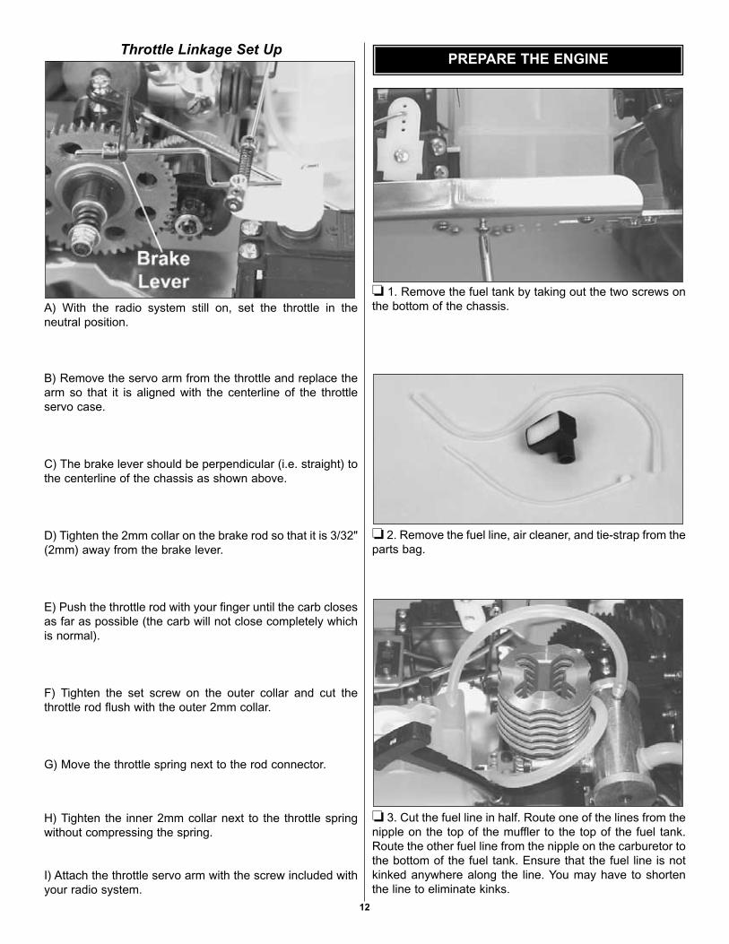
Throttle Linkage Set Up
A) With the radio system still on, set the throttle in theneutral position.
B) Remove the servo arm from the throttle and replace thearm so that it is aligned with the centerline of the throttleservo case.
C) The brake lever should be perpendicular (i.e. straight) tothe centerline of the chassis as shown above.
D) Tighten the 2mm collar on the brake rod so that it is 3/32"(2mm) away from the brake lever.
E) Push the throttle rod with your finger until the carb closesas far as possible (the carb will not close completely whichis normal).
F) Tighten the set screw on the outer collar and cut thethrottle rod flush with the outer 2mm collar.
G) Move the throttle spring next to the rod connector.
H) Tighten the inner 2mm collar next to the throttle springwithout compressing the spring.
I) Attach the throttle servo arm with the screw included withyour radio system.
❏ 1. Remove the fuel tank by taking out the two screws onthe bottom of the chassis.
❏ 2. Remove the fuel line, air cleaner, and tie-strap from theparts bag.
❏ 3. Cut the fuel line in half. Route one of the lines from thenipple on the top of the muffler to the top of the fuel tank.Route the other fuel line from the nipple on the carburetor tothe bottom of the fuel tank. Ensure that the fuel line is notkinked anywhere along the line. You may have to shortenthe line to eliminate kinks.
PREPARE THE ENGINE
12
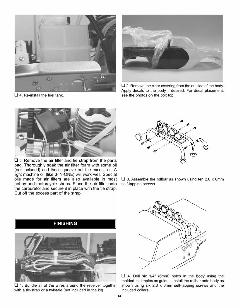
❏ 4. Re-install the fuel tank.
❏ 5. Remove the air filter and tie strap from the partsbag. Thoroughly soak the air filter foam with some oil(not included) and then squeeze out the excess oil. Alight machine oil (like 3-IN-ONE) will work well. Specialoils made for air filters are also available in mosthobby and motorcycle shops. Place the air filter ontothe carburetor and secure it in place with the tie strap.Cut off the excess part of the strap.
❏ 1. Bundle all of the wires around the receiver togetherwith a tie-strap or a twist-tie (not included in the kit).
❏ 2. Remove the clear covering from the outside of the body.Apply decals to the body if desired. For decal placement,see the photos on the box top.
❏ 3. Assemble the rollbar as shown using ten 2.6 x 6mmself-tapping screws.
❏ 4. Drill six 1/4" (6mm) holes in the body using themolded-in dimples as guides. Install the rollbar onto body asshown using six 2.6 x 6mm self-tapping screws and theincluded collars.
FINISHING
13

❏ 5. Drill two 1/4" (6mm) holes in front of body using themolded-in dimples as guides. Install the front brush guardas shown with two 2.6 x 6mm self-tapping screws and thecollars included.
❏ 6. Drill one 1/8" (3mm) hole in each side of the bodyusing the molded-in dimple as a guide, and one 5/64"(2mm) hole 7/16" (11mm) below and 7/16" back from firsthole (use the pegs on the mirror as a guide). Install themirrors as shown with the collars provided.
❏ 7. Mount the body on the body posts and secure the bodyto the truck with (4) body clips.
Congratulations, you have completed assembly! Beforerunning your new truck, please take the time to carefullyread the instructions and watch the video before runningand breaking-in the engine. Make sure you follow the safetyprecautions and most of all...HAVE FUN!
The High-Speed Needle The “high-speed” needle is sticking up from the side of thecarb. It is located in the brass housing, just above the fuelinlet. It controls the fuel to air mixture of the carb. Theneedle is pre-set for break-in from the factory at 2-3/4 turnsout from the fully closed position of the carb. Once theengine is broken-in, the high-speed needle would typicallyrun from 2 to 2-1/2 turns out from closed, depending on theweather, humidity and altitude above sea level. To richenturn the needle counterclockwise, to lean turn the needleclockwise.
CARBURETOR SETTINGS
14

The Low-Speed NeedleThe “low-speed” needle is the screw in the middle of thethrottle arm. It controls the fuel to air mixture at low throttlesettings. There is a simple way of adjusting the low-speedneedle correctly called the “pinch test.” With the engine atidle, pinch the fuel line and listen to how the engine speedsup or slows down. If the engine increases its speed forabout 2 or 3 seconds and then loses speed, the needle isset correctly. If the engine loses RPM quickly, it is set toolean and the low-speed needle needs to be opened(counterclockwise) to richen the mixture. Pinch again tocheck the mixture. If the engine takes longer than 4 secondsto slow down, lean (clockwise) the low-speed needle andthen pinch again to check the mixture.
The Throttle Stop ScrewOn the front of the carburetor, there is a black screw. This iscalled the idle stop screw. This increases or decreases theidle RPM without changing the fuel to air mixture. The barrelshould be approximately 1.5mm (between 1/32" and 1/16")from fully closed.
To insure long life and good performance from your Torq .16engine, you MUST break-in the engine. The break-in periodis critical for long life of the internal parts of the engine. Thisshould be done over the first 4 or 5 tanks of fuel.
Some Things To Remember During Break-In1. Run with the body off. This will keep the engine cooler.2. Keep the air cleaner on at ALL times3. Run on a smooth, hard surface. An empty parking lot is
perfect.4. Use the same fuel that you will use for normal running.5. Resist the urge to accelerate and decelerate the truck
quickly.6. Break-in puts stress on the glow plug and you can burn
it out during break-in. Make sure you have an extra plugor two on hand.
7. Do NOT overheat the engine. You can check the headtemperature by using one of the temperature gaugesthat are available or by putting a drop of water on thetop of the cylinder head. If the water boils awayimmediately, shut off the engine and allow it to cool. If ittakes more than 5 seconds to boil away, the engine isat proper running temperature for break-in.
Before running the engine, read the manual and watch theengine video that came with this kit.
There are several simple steps to starting the engine:1. Install a glow plug. This threads into the top of the
cylinder head.2. Fill the tank - Fill the tank almost to the top. Leave a little
air at the top of the tank.3. Prime the engine - Use the primer button on the fuel tank
to force the fuel through the fuel line. Watch the fuel gothrough the line and when it gets to the carburetor, pressthe primer button once more to get fuel into the engine.
4. Open the high speed needle valve exactly 2-3/4 turns out(counterclockwise) from fully closed. The high-speedneedle is sticking up from the carburetor inside thebrass housing. All of the carburetor settings areadjusted with a flat bladed screwdriver. If you havepreviously run the truck, keep the same needle valvesetting that you used on your last run.
5. Start the engine by pulling the recoil - Use short, quickpulls. DO NOT pull the recoil starter’s string to the end.You only need 10 to 12 inches of pull to start the engine.
Sometimes it is helpful to start the engine at around halfthrottle. Have a friend pull back on the throttle some whileyou start the engine. This may be an indicator that the lowspeed needle setting needs to be adjusted. When theengine starts, immediately return the throttle to idle. If this isnot done the engine can over-rev and cause enginedamage. If the engine is difficult to turn over with therecoil starter, especially if it is brand new, loosen theglow plug a half turn before starting the engine. Thisallows some compression to escape, but the engine willstill start. Make sure you tighten the glow plug after theengine starts. If the recoil starter is still difficult to pull, theengine is flooded – there is too much fuel inside the engine.Remove the glow plug and air cleaner, then turn the engineupside down and pull the recoil 5 or 6 times. This will clearthe engine of fuel, and you will notice the recoil pulls easier.Replace the glow plug and repeat the starting procedure.
FuelsUse fuels that are specially formulated for car and truckengines. DuraTrax Red Alert fuel is specially formulated fortruck engines like the Torq .16.
How To Stop Your EngineYou may have been wondering how to stop the engine. Allyou have to do is pinch the fuel line that runs to thecarburetor and from the bottom of the fuel tank. Pinchingthis will restrict the fuel flow and the engine will quit within afew seconds.
RUNNING THE ENGINE
BREAKING-IN THE ENGINE
15

16
The First Tank Your first tank of fuel should be running the truck at a veryrich high-speed needle valve setting. This allows the fuel tocarry as much oil as possible into the engine to lubricate theinternal parts during the break-in.
1. Open the needle valve 2-3/4 turns from fully closed(counterclockwise). This is factory set already, butcheck it to make sure. When closing the high-speedneedle, close the needle until you feel some resistance.DO NOT overtighten or you will damage the engine.
2. Start the engine. 3. Once the engine is started, open the high-speed needle
valve around 1/8 turn at a time, finding the setting wherethe engine just barely runs. This may take a few timesadjusting the needle, running the truck away from you andback, then adjusting the needle. The truck will performsluggishly and stall from time to time - that is normal.
4. Run the truck back and forth at medium speeds, slowlyaccelerating and decelerating the truck.
5. After a minute or two of running, make sure the engineis not overheating by putting a drop of water on thecylinder head and watching it boil away. If it boils awayimmediately, stop the engine and allow it to cool. Openthe high-speed needle around a 1/4 turn before startingagain. This is a good habit to get into every time you runto ensure that the engine does not overheat during anyrun. Looking at the smoke that comes out the exhaustis also an indicator of how rich or lean the engine isrunning. If there is a good amount of smoke coming outof the exhaust, then chances are good that you arerunning rich.
6. Run the truck back and forth at a medium speed untilthe tank is almost out of fuel. Do not allow the tank torun out of fuel. This leans out the engine and can causeoverheating (See How To Stop Your Engine).
7. Stop the engine and allow the engine to cool before thesecond tank. This normally takes around 10 minutes.
Tanks 2-5 Turn in the needle valve (clockwise) around 1/12 turn fromthe previous setting. Run the truck back and forth. Youshould notice that the truck will perform better during eachrun. Stop the truck periodically to check for overheating. If itis too hot, stop the engine. Wait for it to cool, then open upthe needle valve and restart. After the 5th tank, you shouldbe near to the peak performance of the engine.
10 Ways To Ensure A Long Life From Your Engine:1. Keep your engine clean. Dirt will act as insulation on an
engine. It will not be able to shed heat as easily. Use agood air filter to keep dirt out of your engine and cleanit often.
2. Do not over-lean your engine.3. Do not run your engine with little or no load. Don’t
throttle up the engine to full throttle when the wheels arenot in contact with the ground.
4. Do not overheat the engine. This goes along withkeeping it clean and not over-leaning the engine.
5. Do not use a fuel with a low oil content. Make sure youuse a fuel from a reputable manufacturer, such asDuraTrax Red Alert.
6. Avoid using old fuels in the engine. Always run all of thefuel out of the engine. After running for the day, use anafter-run oil and work it into the engine by turning theflywheel or pulling the engine recoil slowly.
7. Do not use a fuel with a nitromethane (often called nitro)content over 20%.
8. Do not scratch the piston or cylinder sleeve. Avoidjamming something into the exhaust port when removingor re-installing the clutch or flywheel. Use a special toolcalled a crankshaft locking tool, which is installed in theglow plug hole.
9. Do not use silicone sealer on the engine joints. Siliconesealer contains acetic acid, which is corrosive if it getsinside your engine.
10. Do not allow any water inside the engine. This soundseasy, but temperature changes can cause condensationinside the engine. This is a good reason to use an after-run oil. Store your engine inside the house, not ina garage or shed where there will be temperatureextremes.
If you are having problems with your engine consult theengine troubleshooting flow chart on page 16. Thefollowing are some potential problems.
Glow PlugThe glow plug is an item that will wear out and needreplacement from time to time. It is a good idea to removethe glow plug before your first run, heat it and see how wellit glows. You should see a bright orange glow from thefilament. If a coil or two will not glow or the plug will not glowat all, replace the plug. If the engine quits when you removethe glow starter, the plug might need to be changed,although this may be because you are running too rich andneed to screw in your high-speed needle some. Look at theglow plug when you are running the engine. If you see somebubbles coming from around the plug, replace the glow plug(copper) gasket, or both the plug and gasket. The only realway to test a glow plug is to replace it. Make sure you havea spare plug or two on hand every time that you run theMaximum MT.
ENGINE MAINTENANCE

FuelFuel can go bad. The main ingredient in model fuel ismethanol, which is basically an alcohol. Alcohols canabsorb water out of the air, so keep your fuel jug capped atall times. Store your fuel out of the sunlight and in a coolplace. Bad fuel is one of the most difficult problems todiagnose in engines. If you have tried everything you canthink of to remedy an engine that is not running correctly, tryusing some fresh fuel.
Fuel line is susceptible to pinhole leaks. You cannot see thehole in the fuel line, but if you see air bubbles in the linegoing to the carburetor, replace the fuel line. Anothersymptom of a leak in the fuel line is a surging engine. Theproperly tuned engine will surge when the air bubbles hit thecarb. It is basically leaning out the mixture.
To keep dirt out of the engine, we recommend that you usean inline fuel filter on the fuel line running from the fuel tankto the carburetor. Dirt can get caught in the needle seat andcause an inconsistent running engine. If you suspect thatsome dirt has lodged itself in the carb, remove the needlesand clean the carb with denatured alcohol or fuel. It can helpto use compressed air to blow out the fuel passages as well.Dirt can get into your carburetor and engine through the airfilter. Ensure that your air cleaner has a good seal to the topof the carb. Periodically wash the air cleaner foam elementand re-oil the filter. Any air cleaner that has a torn elementor a bad seal should be replaced immediately.
OverheatingOne of the worst things you can do to your engine isoverheat it. The oils that lubricate the engine are carried inthe fuel. If your engine is set too lean, there will not beenough oil in the engine to lubricate the internal parts. Thiswill cause premature wear in the engine and causedamage. We have talked about overheating in other parts ofthis manual, but we want to stress the proper techniques tocheck for overheating. The easiest way of checking thetemperature of the cylinder head is using one of theavailable temperature gauges. This will give you a directreading of the cylinder head temperature. Do not let thehead temperature exceed 220° Fahrenheit (104° Celsius).Another way of checking the head temperature is to put adrop of water on the cylinder head. If it boils awayimmediately, the high-speed needle is set too lean. If thewater boils away in 3-5 seconds, the engine is within properoperating temperatures. If the water boils away longer than5 seconds, the mixture is set rich which is preferable whenbreaking in the engine. Otherwise lean the mixture someand retest after a minute of running.
Ride Height: This refers to the clearance between theground and the chassis, both at the front and the back of thetruck. The ride height on the Maximum MT should beapproximately 2-3/8" (60mm). To determine the ride height,drop the truck from around 6"-12" above flat ground. Dropthe truck, making sure it drops flat. Check where thesuspension arms come to rest. You can adjust ride bymoving the spring adjusters on the shock (which are at thetop of each shock spring) until the appropriate height isachieved after the drop test.
Toe-In/Toe-Out: This refers to the angle of the front tireswhen viewed from above when the suspension arms arelevel. If the fronts of the tires angle in, it is called “toe-in” andif the fronts of the tires angle out, it is called “toe-out.” Thisis adjusted by turning the steering rods - the rods that runbetween the front hub and the servo saver. These areturnbuckle type, which means you do not have to removethe rods to make adjustments in length. Turning the rod inone direction will lengthen, turning the rod the oppositedirection will shorten. Normally a small amount of toe-in isused to make the truck track straight at high speed. Toomuch toe-in will make the truck difficult to turn as well asreduce the overall top speed because of tire scrub.Sometimes a small amount of toe-out will be used to helpthe steering. As a general rule use a small amount of toe-in.
Camber: Camber is the angle of the tops of the tires whenviewed from the front. Negative camber is when the tops ofthe tires are angled towards the center of the truck. Positivecamber is where the tops of the tires are angled away fromthe center of the truck. Positive camber is very rarely used,if ever. A small amount of rear negative camber is helpful toincrease traction in the rear. Negative camber at the frontwill increase stability. Camber adjustments can be made onthe Maximum MT by turning the “camber rods,” which arethe upper links on the suspension. The camber links arealso turnbuckle type. Lengthening the camber rod will addpositive camber and shortening the camber rod will addnegative camber.
PERFORMANCE TUNING
17
Shocks: Changes in shock oils, springs, and pre-load on thesprings can dramatically change the way the car handles. Athicker shock oil will make the truck turn faster but reducesoverall traction and handling over bumpy surfaces. Thinneroil will increase traction at the expense of steering responseand the car will tend to roll more. In general, shock oilsbetween 20 and 40 weight will be best for your truck. Youshould experiment some to see what oils work best for yourtrack and driving style. Shock springs affect the rate that thesuspension rebounds from a bump. We have supplied softsprings that work under most conditions. Other springs areavailable from DuraTrax. Pre-load on the springs meansthat the springs are already compressed some so that thesuspension will rebound faster. Sometimes you will want topre-load one side when the track has turns all or mostly inone direction, for instance an oval track. It will also increasethe ride height.
Slipper Clutch: The slipper clutch is attached to the spurgear on your truck, the large gear on the outside of thetransmission. This clutch will slip when too much power issent to the wheels. It has adjustable tension by turning thenut on the shaft. This is designed to maximize traction onvarious surfaces by slipping before the wheels do. To adjustthe slipper clutch, run the truck on the surface you plan torace. If the rear wheels spin when full power is applied froma stop, loosen the nut until the wheels do not spin any more.If the wheels do not spin, tighten the nut until the wheelsspin and then loosen the nut some.
Before Each Run • Check for loosened screws on the truck. Engine vibration
will loosen some of the screws, particularly in the enginemount area. Use thread lock on screws that thread intometal parts or use a metal nut.
• Inspect the air cleaner for a torn or damaged element.Also look for dirt in the air cleaner element and wash it ifnecessary.
• Check the suspension and drive train for binding.• Inspect all of the wires for damage. Also check the
connectors to make sure all of them are tight and in theproper place.
• Check the fuel tank and fuel lines for leaks.
• Before starting the engine, turn on the radio and makesure the servos move easily and in the right direction.
• Before running always check the condition of your radiosystem batteries and replace/recharge if necessary.
After Each Run • Drain the fuel tank of any leftover fuel. DO NOT return it
to your fuel jug.
• Put some after-run oil in the carb and turn the flywheelseveral times to work the oil into the engine. This willprotect the engine from rusting, especially when storedfor a long period of time.
• Check again for loosened screws.
• CLEAN the truck. Wipe off any oils that have collectedon the chassis, engine end exhaust. Oils will attract dirton the next run.
MAINTENANCE TIPS
18
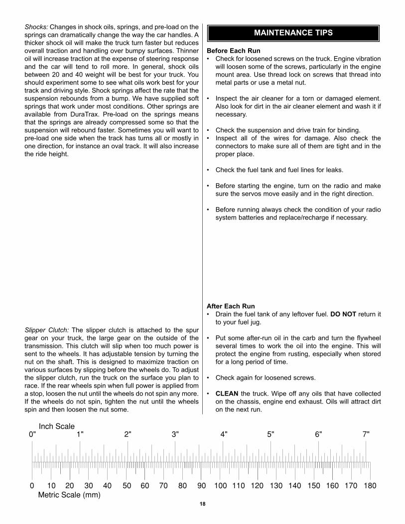
0" 1" 2" 3" 4" 5" 6" 7"
0 10 20 30 40 50 60 70 80 90 100 110 120 130 140 150 160 170 180
Inch Scale
Metric Scale (mm)
19
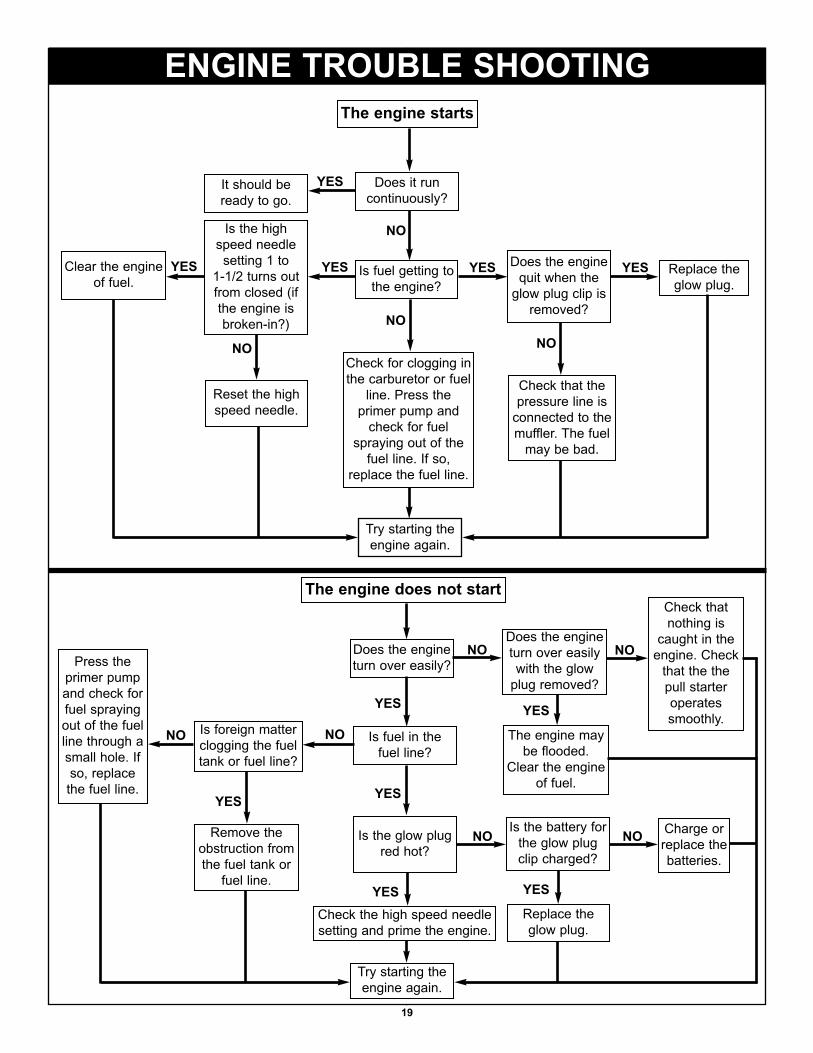
ENGINE TROUBLE SHOOTINGThe engine starts
Does the engineturn over easily?
Does it runcontinuously?
Is fuel getting tothe engine?
Check for clogging inthe carburetor or fuel
line. Press theprimer pump and
check for fuelspraying out of the
fuel line. If so,replace the fuel line.
Is fuel in the fuel line?
Is the glow plugred hot?
Check the high speed needlesetting and prime the engine.
Is foreign matterclogging the fueltank or fuel line?
Is the battery forthe glow plugclip charged?
It should beready to go.
Is the highspeed needlesetting 1 to
1-1/2 turns outfrom closed (ifthe engine isbroken-in?)
Try starting theengine again.
NO
NO
NO
NO
YES
YES
YES
YES
YES
Does the enginequit when the
glow plug clip isremoved?
YESYESClear the engineof fuel.
NO
Reset the highspeed needle.
YES
NO
Replace theglow plug.
Check that thepressure line is
connected to themuffler. The fuel
may be bad.
The engine does not start
NODoes the engineturn over easilywith the glow
plug removed?
The engine maybe flooded.
Clear the engineof fuel.
YES
Check thatnothing is
caught in theengine. Check
that the thepull starteroperatessmoothly.
NO
Press theprimer pumpand check forfuel sprayingout of the fuelline through asmall hole. Ifso, replacethe fuel line. YES
Remove theobstruction fromthe fuel tank or
fuel line.
NO NOCharge orreplace thebatteries.
YES
Replace theglow plug.
Try starting theengine again.

RECOMMENDED ACCESSORIES
DuraTrax Deluxe Glow Plug Wrench
This single, heavy-duty, plated steel toolhandles FIVE metric hex sizes: 7-, 8-, 10-, 12-and 17mm—and includes a special 10mmsocket for pilot shafts! Threaded holes tappedbetween the wrenches store up to four spareglow plugs. DTXR1170
DuraTrax Red Alert™ 20% Racing Fuel
To make your TORQ™ 21 engine run faster,better and longer, you need the uniqueformula of DuraTrax Red Alert. Red Alertcontains 20% nitro plus a carefully race-testedblend of castor and synthetic oils. DTXP0600
DuraTrax Nitro Starter Set
This set includes everything you need to startracing. 5-way glow plug wrench, 1 qt. of RedAlert fuel, Hobbico® glow starter w/charger,fuel bottle and glow plug. DTXP0200
DuraTrax Crankshaft Locking Tool
Remove your engine’s clutch safely with thiseasy to use, anodized metal tool. Workswith all .10 to .21 car and buggy engines.
DTXR1100
DuraTrax XL Field Bag
Keep your gear loaded and race ready withthe XL field bag. Heavy duty black nylon bagwith red trim and white logo. DTXP2000
DuraTrax Body Repair Tape
Need a quick, easy fix for Lexan® body damage?When used with Shoe Goo II fixit compound(DTXC2460), the tape's open weave, nylonmesh design offers enough flexibility to preventfuture cracking. DTXR1210
DuraTrax Bearing Completer Set
Reduce friction, drag and extend the life ofyour Maximum MT's parts with this ballbearing set. Includes all sizes needed toreplace the bushings included with yourMaximum MT. DTXC2541
DuraTrax Kwik-Pit™ 500cc Fuel Bottle
Fast, clean pit stops are as close as the Kwik-PitFuel Bottle. The long, angled neck reacheseasily into your tank to prevent fuel spills, theclear plastic body keeps the fuel level in plainsight and moving fuel from the bottle to your tanktakes just a gentle squeeze. DTXP0150
DuraTrax 4-Shoe Clutch Kit
Tweak your Maximum MT for amazingacceleration! This kit increases surface areacompared to 3-shoe clutch designs for animproved clutch bell grip. Requires bearings(DTXC1535) and clutch bells (DTXC2521-DTXC2526). DTXC2541