ASSEMBLY AND INSTALLATION INSTRUCTIONS for...
10
Newer construction methods have led to an increase in air and water tightness in buildings. This frequently leads to negative air pressure inside the house, which can draw water through very small openings. Our installation method integrates the door to the weather barrier of the structure (typically building wrap) and uses a sill pan to capture and drain incidental storm water from under the door to the exterior. Thank you for selecting JELD-WEN products. Attached are JELD-WEN’s recommended installation instructions for Siteline/W-4500 Folding Doors. Read these instructions thoroughly before beginning. They are designed to work in most existing applications, however; existing conditions may require use of alternative methods to these instructions. If changes are needed, they are made at the installer’s risk. For installations other than indicated in these instructions, contact a building professional. To adequately protect your door, please refer to “Appropriate Protection for Exterior Doors” for information on protection requirements at www.jeld-wen.com. IMPORTANT INFORMATION AND GLOSSARY LANDINGS These instructions cover two door sill conditions: the step-down landing and the continuous slab landing. The installation methods vary slightly between landing types. Not all exterior door types may be installed into every wall condition in all areas. See our Appropriate Protection document for overhang requirements at www.jeld-wen.com. Consult your local building code official (or Authority having jurisdiction) for applicable building codes and regulations. Local building code requirements supersede recommended installation instructions. Please Note! Any door installation such that the sill is higher than 35 feet above ground level or into a wall condition not specifically addressed in these instructions must be designed by an architect or structural engineer. We recommend that all non pre-finished wood or fiberglass components be finished with an appropriate paint or stain prior to installation. See our Finishing document for details at www.jeld-wen.com. Failure to properly finish or install square, level and plumb and on a flat surface (without peak and valleys) could result in denial of warranty claims for operational or performance problems. Note to Installer: Provide a copy of these instructions to the building owner. By installing this product, you acknowledge the terms and conditions of the limited warranty as part of the terms of the sale. GLOSSARY Backer Rod (backing material) A material (e.g. foam rod) placed into a joint primarily to control the depth of the sealant. Buck A wood framework attached to the masonry inside a window or a door rough opening. Continuous Air Seal Backer rod and sealant or low expansion foam applied to the interior gap between the product and the building in a continuous fashion used to block air flow between the interior and exterior of the building envelope. Pilot Hole A drilled hole that is no larger than the body of the screw (minus the threads). Rough Opening The framed opening in a wall where a door is to be installed. Estimated Install Time for New Construction First Time: 6 hr. Experienced: 5 hr. Professional: 4 hr. 1 2 3 4 5 6 7 8 9 10 11 12 Continuous Slab Landing Step-Down Landing Please allow sufficient time to properly prepare the rough opening, install the door, and ensure its proper operation. Shiplap The layering method in which each layer overlaps the layer below it so that water runs down the outside. Sill Pan A flashing component installed in the sill of the rough opening underneath the door. Sill pans have upturned walls along the interior edge and at both ends, creating a three sided box. This component serves as a collection device to drain incidental water to the exterior of the building and should be properly sealed to the opening. The best sill pan design has a positive slope to the exterior and offers continuous support to the door’s sill. ASSEMBLY AND INSTALLATION INSTRUCTIONS for Siteline/W-4500 Folding Doors (JII041)
Transcript of ASSEMBLY AND INSTALLATION INSTRUCTIONS for...

Newer construction methods have led to an increase in air and water tightness in buildings. This frequently leads to negative air pressure inside the house, which can draw water through very small openings. Our installation method integrates the door to the weather barrier of the structure (typically building wrap) and uses a sill pan to capture and drain incidental storm water from under the door to the exterior.
Thank you for selecting JELD-WEN products. Attached are JELD-WEN’s recommended installation instructions for Siteline/W-4500 Folding Doors. Read these instructions thoroughly before beginning. They are designed to work in most existing applications, however; existing conditions may require use of alternative methods to these instructions. If changes are needed, they are made at the installer’s risk. For installations other than indicated in these instructions, contact a building professional. To adequately protect your door, please refer to “Appropriate Protection for Exterior Doors” for information on protection requirements at www.jeld-wen.com.
IMPORTANT INFORMATION AND GLOSSARY
LANDINGS
These instructions cover two door sill conditions: the step-down landing and the continuous slab landing. The installation methods vary slightly between landing types.
Not all exterior door types may be installed into every wall condition in all areas. See our Appropriate Protection document for overhang requirements at www.jeld-wen.com. Consult your local building code official (or Authority having jurisdiction) for applicable building codes and regulations. Local building code requirements supersede recommended installation instructions.Please Note! Any door installation such that the sill is higher than 35 feet above ground level or into a wall condition not specifically addressed in these instructions must be designed by an architect or structural engineer. We recommend that all non pre-finished wood or fiberglass components be finished with an appropriate paint or stain prior to installation. See our Finishing document for details at www.jeld-wen.com. Failure to properly finish or install square, level and plumb and on a flat surface (without peak and valleys) could result in denial of warranty claims for operational or performance problems.Note to Installer: Provide a copy of these instructions to the building owner. By installing this product, you acknowledge the terms and conditions of the limited warranty as part of the terms of the sale.
GLOSSARY
Backer Rod (backing material)A material (e.g. foam rod) placed into a joint primarily to control the depth of the sealant.BuckA wood framework attached to the masonry inside a window or a door rough opening.Continuous Air SealBacker rod and sealant or low expansion foam applied to the interior gap between the product and the building in a continuous fashion used to block air flow between the interior and exterior of the building envelope.Pilot HoleA drilled hole that is no larger than the body of the screw (minus the threads).Rough OpeningThe framed opening in a wall where a door is to be installed.
Estimated Install Time for New Construction
First Time: 6 hr.
Experienced: 5 hr.
Professional: 4 hr.
12
3
45
67
8
9
1011 12
Continuous Slab Landing
Step-Down Landing
Please allow sufficient time to properly prepare the rough opening, install the door, and ensure its proper operation.
ShiplapThe layering method in which each layer overlaps the layer below it so that water runs down the outside.Sill PanA flashing component installed in the sill of the rough opening underneath the door. Sill pans have upturned walls along the interior edge and at both ends, creating a three sided box. This component serves as a collection device to drain incidental water to the exterior of the building and should be properly sealed to the opening. The best sill pan design has a positive slope to the exterior and offers continuous support to the door’s sill.
ASSEMBLY AND INSTALLATION INSTRUCTIONSfor Siteline/W-4500 Folding Doors (JII041)

2
SAFETY
• Read and fully understand ALL manufacturer’s instructions before beginning. Failure to follow proper installation and finishing instructions may result in the denial of warranty claims for operational or performance problems.
• Do not work alone. Two or more people are required. Use safe lifting techniques.
• Use caution when handling glass. Broken or cracked glass can cause serious injury.
• Wear protective gear (e.g. safety glasses, gloves, ear protection, etc.).• Operate hand/power tools safely and follow manufacturer’s
operating instructions.• Use caution when working at elevated heights.• If disturbing existing paint, take proper precautions if lead paint is
suspected (commonly used before 1979). Your regional EPA (www.epa.gov/lead) or Consumer Product Safety Commission offices provide information regarding regulations and lead protection.
• WARNING: Drilling, sawing, sanding or machining wood products generates wood dust, a substance known to the State of California to cause cancer. Use a respirator or other safeguards to avoid inhaling wood dust.
MATERIALS AND DOOR HANDLING
• Heed material manufacturer’s handling and application instructions.
• Protect adhesive surfaces from dirt, moisture, direct sunlight and folding over onto themselves.
• Handle in vertical position; do not drag on floor.
• Do not put stress on joints, corners or frames.
• Store door in dry, well-ventilated area in vertical, leaning position to allow air circulation; do not stack horizontally.
• Protect from exposure to direct sunlight during storage.
• Install only into vertical walls and when conditions are dry.
IF INJURY OCCURS, IMMEDIATELY SEEK MEDICAL ATTENTION!
FULLY SHEATHED AND OPEN-STUD WALL CONSTRUCTION
The door will be mounted inside of the rough opening. This installation assumes building wrap is properly installed prior to installation.
This installation guide specifically addresses masonry/block wall, sheathed wall and open-stud construction.
MASONRY/BLOCK WALL CONSTRUCTION
This installation assumes that a building professional has already properly fastened and sealed a framework of studs (often called a buck) to the concrete/masonry wall. Buck
Trimmer studs
Header
SheathingSill area
Building wrap
King stud
ROUGH OPENINGS
SAFETY AND HANDLING
MATERIALS AND TOOLS
#10 x 2½"
#10 x 1"
#8 x 3/8"
#10 x 1½"
#6 x 1"
PROVIDED MATERIALS
Note! Specific parts shown are dependent upon product configuration and every part will not apply to all configurations.
• #8 x 3/8" screws for cover plate.
• #6 x 1" flat head screws for pivot hardware installation.
• #10 x 1" screws for center wall pivot and housing.
• #10 x 1½" flat head screws to fasten hinges to panels.
• #10 x 2½" flat head screws for frame assembly and securing the door frame (side jambs, head and sill track) into framing. If installing the sill onto concrete, these screws will need to be replaced with masonry fasteners. See the Needed Materials section for appropriate fasteners to use in concrete.
ASSEMBLY AND INSTALLATION INSTRUCTIONSfor Siteline/W-4500 Folding Doors (JII041)

3
NEEDED MATERIALS
Note! JELD-WEN exterior window and door products should be installed in accordance with JELD-WEN’s recommended installation and flashing directions, which are shipped with the products or can be found on our website: www.jeld-wen.com. Note that alternative installation methods and flashing systems may be utilized at the installer’s or owner’s discretion and, in such situations the installation should be done in accordance with the flashing manufacturer’s instructions. Follow all material manufacturer’s instructions for proper use and compatibility. When using flashing, spray adhesive/primer, sealant and foam products, we recommend using the same manufacturer and verifying compatibility. It is the End User’s responsibility to determine if dissimilar materials are compatible to the substrates in the application.• 3/16" masonry screws (such as Tapcon® ) for sill installation onto
concrete. Screws must penetrate at least 1½" into substrate.• Non-compressible or non-water degradable shims.• Sill pan: It is best practice to use a pre-formed, rigid, positively
sloped, pvc pan that provides continuous support. We recommend using SureSill™ Sloped Sill Pan™ , manufactured by SureSill™, Ltd. An alternative would be a non-sloped pre-formed sill pan or one can be fabricated on site from metal or vinyl sheet material with the proper tools.
• Sealant: We recommend OSI® QUAD® Max Sealant or equivalent. This can be used in any application and can be painted or ordered in a color matched product, if desired.
• Backer rod 1/8" larger than the widest portion of the gap (used in conjunction with sealant bead).• Polyurethane low expansion Window and Door foam: We recommend
OSI® QUAD® Foam or equivalent).• 4", 6", or 9" (as required by local code and window configuration)
wide self-adhered flashing: We recommend OSI® QUAD® Butyl Flash Tape or equivalent.
• Spray adhesive/primer for self-adhered flashing. Such as Loctite® 300 or equivalent. Follow manufacturer’s instructions for application methods.
• Drip cap if required because of door location and exposure. Doors with an adequate overhang (see our Appropriate Protection document at www.jeld-wen.com) may not need a drip cap. In addition to sill pans, SureSill™ also offers types of head flashing.
FOR INSTALLATIONS INTO A BUCK:• Liquid applied flashing (Protecto Wrap LWM 200 or equivalent).
INCLUDED PARTS - CONTINUED
ATTACHED TO PANELS• Hinge set (may include handle) - #10 x 1½" screws• Flush bolt(s)• Multi-point locking hardware strikes• Astragal
SHIPPED LOOSE• Head track• Sill track• Top and bottom intermediate
(4-wheel) carrier guide set with hinge leaf (dependent upon configuration)
• Top and bottom intermediate (2-wheel) carrier with hinge leaf (dependent upon configuration)
• Upper wall pivot - #6 x 1" screws• Lower wall pivot - #6 x 1" screws
• Center wall pivot and housing with screws - #10 x 1"
• Sill track seal• Handle set (optional and/or
dependent upon configuration)• Lower pivot cover and screws -
#8 x 3/8"• Clad astragal cover (2) -
(dependent upon configuration)• Pivot support gasket
Flush Bolt
Center Wall Pivot with Housing
Hinge Set
Top Intermediate Guide
Top Directional Guide
Lower Pivot Cover
Intermediate Carrier Set(Four Wheel)
Directional Carrier Set(Two Wheel)
Lower Wall Pivot
Upper Wall Pivot
ATTACHED TO PANELS
SHIPPED LOOSE
Head Track
Sill Track Seal
Pivot Support Gasket
MATERIALS AND TOOLS - CONTINUED
HandleCenter Pivot Hinge Leaf
Sill Track
NEEDED TOOLS
• Tape measure• Utility knife• Level (3' and 6' recommended)• J-roller• Caulking gun• Vacuum for removing debris
from sill track• Drill and Impact driver (optional)
with bits
• Spade bit (3/4" for center pivot)• Denatured alcohol (for installing
clad astragal covers)• Screwdrivers (small) for sill carrier
adjustment• 14 mm open end wrench (panel
adjustment only)• Step Ladder (2)
ASSEMBLY AND INSTALLATION INSTRUCTIONSfor Siteline/W-4500 Folding Doors (JII041)

4
The sill can be prepared using one of two methods: We recommend SureSill™ Sloped Sill Pan™ available from SureSill at www.suresill.com, building supply stores, and some manufacturing locations or fabricate a sill pan on site. If installing a SureSill™ sill pan, follow SureSill’s instructions for installation and skip to section 4 “PREPARE BUCK“, or to section 5, “PREPARE STUD-FRAMED WALL“ as it applies to your situation. If fabricating a sill pan on the job site, follow the instructions below.
JOBSITE FABRICATED SILL PAN
1. Cut a piece of sheet material to the length shown.
2. Lightly crease folding lines 1/2" in from the two short sides and one long side.
3. Measure the width of the sill and add 9/16". NOTE: If jamb extension has been applied to the frame it may need to be modified in a manner to allow for a sill pan to make contact with the interior part of the sill.
4. Take this distance from the back edge and lightly crease a folding line across the sheet material.
5. For step-down landings, cut 1/2" in at this line on both sides of the sheet material.
• Verify the width and height of the door frame are each 1/2"-3/4" smaller than the rough opening width/height.
• Verify the rough opening is square. The (A) and (B) measurements should be the same. Maximum allowable deviation from square is 1/4".
• Verify the rough opening is plumb and level (C, E and D). The maximum allowable deviation is 1/16" for every 2' of rough opening (not to exceed 1/8").
• The rough opening sill must not be crowned or sagged (D), but rather level or sloped (positive slope) to the exterior.
A
D
C E
B
Verify Square, Level, and Plumb
REMOVE PACKAGING
Remove shipping materials such as corner covers, shipping blocks or pads.
INSPECT DOOR
• Cosmetic damage.
6. For continuous slab, cut across the folding line.
7. Fold the three back sides up to make a 3-sided box, and for step-down landings, fold the front flap down.
INSTALL SILL PAN
1. Set the sill pan in the rough opening, aligning the front edge (for continuous slab) or folded down edge (for step-down) with the exterior of the rough opening.
2. Mark a line across the front and back of the sill pan.
3. Apply three 3/8" beads of sealant between the lines.
4. Place the sill pan in the rough opening. Firmly press the sill pan into the sealant with a J-roller.
Sealant
• Correct product (size, color, grid pattern, handing, glazing, energy-efficiency requirements, etc.).
If any of the above conditions represent a concern, or if you expect environmental conditions to exceed the door’s performance rating, do not install the door. Contact your dealer or distributor for recommendations.
• The exterior face of the rough opening must be in a single plane (E) with less than 1/8" twist from corner to corner.
• In wood frame construction, the header must be supported by trimmer studs and designed to ensure that no load is transferred to patio door unit.
• Correct any deviations before installing the patio door. Consult a building professional as needed.
• Verify the rough opening is clean and dry.
FOR RETROFIT INSTALLATIONS
After removing the old door, remove sufficient cladding (siding, stucco, etc.) to expose enough intact building wrap to properly seal the door system to the opening. If damaged, apply new building wrap in shiplap manner. Verify the rough opening framing is structurally sound. Contact your local waste management entities for proper disposal or recycling of products being removed.
½" ½"
½" ½"
Sill width + 9/16"
Folding Line
Length of rough opening sill plus 1"
Fold sides and back up
Fold corner forward
Fold front flap down
Remove for continuous slab
REMOVE PACKAGING AND INSPECT DOOR
INSPECT ROUGH OPENING
INSTALL SILL PAN
1
2
3
ASSEMBLY AND INSTALLATION INSTRUCTIONSfor Siteline/W-4500 Folding Doors (JII041)

5
5. Cut two pieces of self-adhered flashing 9" wide by the sill pan width + 3" long.a. For continuous
slab landings only, cut out the inside corner.
b. Adhere the pieces of flashing to the inside corners. Stretch flashing as needed to cover corners and lay flat.
6. Smooth gaps or bubbles beneath self-adhered flashing with a J-roller (remove and replace if necessary).
7. Seal back corners of sill pan with sealant.
8. For step-down landings only, cut plastic drain screen to length of sill + 2" and staple 1/2" below sill edge. The drain screen provides a path for air to dry any incidental moisture in the rough opening.
End of Stud-Framed Wall Instructions, continue with section 6, “INSTALL DOOR.”
PREPARE BUILDING WRAP
Verify these steps are allowed by the building wrap manufacturer.1. Trim the sides
sufficiently to allow the nailing fin to be mounted against the sheathing.
2. If the door extends beyond the exterior plane of the building and a drip cap is desired, at the head, slit building wrap 6" at 45°. Tape up as shown. We recommend installing a drip cap because this integrates the building wrap and drip cap to protect the structure and the product from incidental water.
INSTALL JOBSITE FABRICATED SILL PAN
Note! The rest of the steps in this section only apply to a job site fabricated sill pan. If installing a sill pan that you have purchased, follow manufacturer’s instructions for installation and skip to section 6, “INSTALL DOOR.”3. Apply spray adhesive/primer to the sill pan and surrounding area.
Follow manufacturer’s instructions for application methods.4. Cut a piece of self-
adhered flashing the length of the sill and apply over the sill pan as shown. The bottom of the sill pan should be completely covered by the self-adhered flashing. For step-down landings, fold flashing down as shown. For continuous slabs, trim flush with rough opening.
45˚6"
Sill pan width
3"
9"
Discard (for
continuous slab only)
Continuous Slab Landing
Sill pan width
6"
3" Step-Down Landing
Sill pan width
6"
3"
Note! This section applies to installations into a buck only. For installations into a stud-framed wall, begin with section 5, “PREPARE STUD-FRAMED WALL.”1. Seal any joint larger than 1/16" in the buck and between the buck
and the concrete/masonry with sealant.2. Cover the buck and the surrounding concrete/masonry at the head
and jambs (apply over sill pan if installing a job site fabricated sill pan) with liquid applied or self-adhered flashing. If using self-adhered flashing, follow manufacturer’s instructions for appropriate use of primers and other application methods.
END of Buck Instructions, SKIP to section 6, “INSTALL DOOR.”
Sealant
Sealant joints
Liquid applied flashing
PREPARE BUCK
PREPARE STUD-FRAMED WALL
4
5
ASSEMBLY AND INSTALLATION INSTRUCTIONSfor Siteline/W-4500 Folding Doors (JII041)
6
INSTALL DOOR6
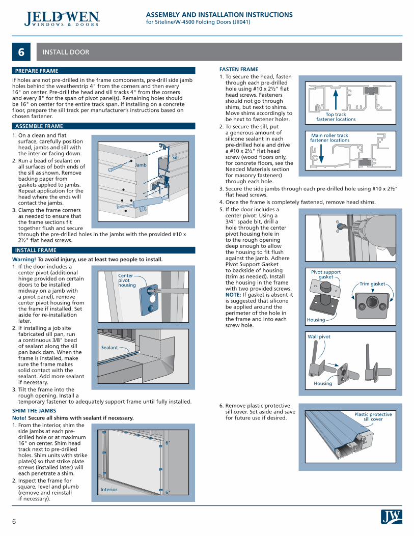
PREPARE FRAME
If holes are not pre-drilled in the frame components, pre-drill side jamb holes behind the weatherstrip 4" from the corners and then every 16" on center. Pre-drill the head and sill tracks 4" from the corners and every 8" for the span of pivot panel(s). Remaining holes should be 16" on center for the entire track span. If installing on a concrete floor, prepare the sill track per manufacturer’s instructions based on chosen fastener.
ASSEMBLE FRAME
1. On a clean and flat surface, carefully position head, jambs and sill with the interior facing down.
2. Run a bead of sealant on all surfaces of both ends of the sill as shown. Remove backing paper from gaskets applied to jambs. Repeat application for the head where the ends will contact the jambs.
3. Clamp the frame corners as needed to ensure that the frame sections fit together flush and secure through the pre-drilled holes in the jambs with the provided #10 x 2½" flat head screws.
INSTALL FRAME
Warning! To avoid injury, use at least two people to install.1. If the door includes a
center pivot (additional hinge provided on certain doors to be installed midway on a jamb with a pivot panel), remove center pivot housing from the frame if installed. Set aside for re-installation later.
2. If installing a job site fabricated sill pan, run a continuous 3/8" bead of sealant along the sill pan back dam. When the frame is installed, make sure the frame makes solid contact with the sealant. Add more sealant if necessary.
3. Tilt the frame into the rough opening. Install a temporary fastener to adequately support frame until fully installed.
SHIM THE JAMBSNote! Secure all shims with sealant if necessary. 1. From the interior, shim the
side jambs at each pre-drilled hole or at maximum 16" on center. Shim head track next to pre-drilled holes. Shim units with strike plate(s) so that strike plate screws (installed later) will each penetrate a shim.
2. Inspect the frame for square, level and plumb (remove and reinstall if necessary).
Sill
Jamb
FASTEN FRAME1. To secure the head, fasten
through each pre-drilled hole using #10 x 2½" flat head screws. Fasteners should not go through shims, but next to shims. Move shims accordingly to be next to fastener holes.
2. To secure the sill, put a generous amount of silicone sealant in each pre-drilled hole and drive a #10 x 2½" flat head screw (wood floors only, for concrete floors, see the Needed Materials section for masonry fasteners) through each hole.
3. Secure the side jambs through each pre-drilled hole using #10 x 2½" flat head screws.
4. Once the frame is completely fastened, remove head shims.5. If the door includes a
center pivot: Using a 3/4" spade bit, drill a hole through the center pivot housing hole in to the rough opening deep enough to allow the housing to fit flush against the jamb. Adhere Pivot Support Gasket to backside of housing (trim as needed). Install the housing in the frame with two provided screws. NOTE: If gasket is absent it is suggested that silicone be applied around the perimeter of the hole in the frame and into each screw hole.
6. Remove plastic protective sill cover. Set aside and save for future use if desired.
Main roller track fastener locations
Sealant
Top track fastener locations
6"
6"Interior
Plastic protective sill cover
Pivot support gasket
Housing
Housing
Wall pivot
Trim gasket
Center pivot housing
ASSEMBLY AND INSTALLATION INSTRUCTIONSfor Siteline/W-4500 Folding Doors (JII041)

7
INSTALL DOOR - CONTINUED6INSTALL HARDWARE1. Identify handing and operation of door unit. Locate matching
configuration on schematic and circle it. Panels are numbered according to installed position, left to right, as viewed from the exterior/clad surface.
2 Left 4 Left
4 Right
2 Left 2 Right
3 Left 1 Right
1 Left 3 Right
2 Right
3 Left
2 Left 1 Right
1 Left 2 Right
3 Right
Interior Interior
Interior Interior
Interior Interior
Interior Interior
Interior Interior
Interior
Exterior Exterior
Exterior Exterior
Exterior
Order of Installation
Order of Installation Order of Installation
Order of Installation
Order of InstallationOrder of Installation
Order of Installation Order of Installation
Order of Installation
Order of InstallationOrder of Installation
Order of Installation
Exterior
Exterior Exterior
Exterior Exterior
Exterior
LEGEND
Pivot Flush bolt Intermediate Carrier
Handle Handle set Directional/Handed Carrier
1 2 1 2 3 4
1 2 3 4
1 2 3 4
1 2 3 4
1 2 3 4
1 2
1 2 3
1 2 3
1 2 3
1 2 3
ASSEMBLY AND INSTALLATION INSTRUCTIONSfor Siteline/W-4500 Folding Doors (JII041)

8
INSTALL DOOR - CONTINUED6INSTALL HARDWARE - CONTINUED1. Remove hardware from bag. Match the hardware boxes to names on
the schematic. Arrange hardware so that it matches the hardware layout within the schematic.
2. To avoid damage to the rollers, clean all debris from the head and sill track.
3. Locate the cut out near the end of the sill track and insert the properly handed Directional Carrier Set (two wheel) and/or Intermediate Carrier Set (one or both dependent upon configuration). Carriers should be positioned so that the tapered wheels face towards the interior and the horizontal wheels face towards the exterior.
4. Insert the properly handed pivot hinge. Hinge should be inserted so that the heel, with the two screw holes, is towards the interior of the sill track. Slide all the way against jamb.
Secure the lower pivot hinge to sill track with two #6 x 1" screws.
Apply the aluminum sill cover plate on top of the lower pivot hinge and secure with two #8 x 3/8" screws.
5. Locate the cut out near the end of the head track and insert the proper upper track guide (as paired in the box with the lower track carrier set).
6. Install the properly handed upper pivot hinge. Align the metal hinge plate with the plastic housing and secure the hinge to upper track with four #6 x 1" screws.
7. Press the weatherstrip back into the head track.
Cutout
Sill cover plate
CutoutWeatherstrip
Upper track pivot guide
Upper pivot hinge
Weatherstrip
Head
Exterior
Exterior
Exterior
Exterior
Four Wheel Carrier setshown
Pivot hinge
Sill
ASSEMBLY AND INSTALLATION INSTRUCTIONSfor Siteline/W-4500 Folding Doors (JII041)

9
INSTALL DOOR - CONTINUED6
INSTALL PANELS
Study the overall door configuration before installation. Begin panel installation from the pivot panel at side jamb and continue toward center. Panels are numbered according to installed position, from the outside, left to right.
Some hinge screws are pre-installed in the edge of the panels that have flush bolts. These screws are shorter than the other hinge screws and must be removed to install the hinge and then re-installed in the same location. This is to eliminate interference between the hinge screws and flush bolt.
FIRST PANEL (PIVOT PANEL)Note! Steps 1 and 2 will work on lighter panels. Skip to steps 3 and 4 if working with taller/heavier panels.(THREE HINGES OR LESS)1. Install hinge leaf on
lower end of panel with provided #10 x 1½" flat head screws.
2. Hold the door in the vertical position. Lift, align and then set the lower hinge onto the pivot pin installed into the sill. Ensure the panel does not make contact with the head of the door frame during process. With the door panel supported, rotate to the fully opened position.
(UNITS WITH FOUR HINGES)3. Slide hinge leaf onto pivot pin installed into the sill. Orientate the
hinge to simulate a fully opened position. Lift and set the door panel adjacent to the hinge leaf. Ensure the panel does not make contact with the head of the door frame during process. (NOTE: Additional wood blocking or shimming may be used under the door panel to assist with alignment).
4. With the panel supported, secure the hinge leaf to the edge of the panel with provided #10 x 1½" flat head screws.
5. If installing a door panel with a center pivot, place the long leg of the pin into the barrel of the hinge leaf on the panel. Tilt panel toward jamb so that the short pin engages the housing in the jamb.
6. Slide the top hinge leaf onto the upper pivot and align the top of the panel with the hinge leaf. Fasten the leaf to the door panel with the #10 x 1½" flat head screws.
7. If door configuration has panel(s) pivoting from both ends, then repeat steps above at other side of door frame. Additionally, if the door only pivots from the RH side of the frame then start the panel installation from the right (this will require the highest number panel, 3 or 4, to be installed first and the lower numbered panel installed last).
SECOND PANEL (HINGE PANEL)1. Hold the pivot door panel in the open position. Place the second door
panel next to first wood face to wood face and align the tops of the door panels and the hinges.
2. If present, make sure the center pull handle is to the inside. Secure hinges with the provided #10 x 1½" flat head screws.
THIRD/ADDITIONAL PANEL (CARRIER PANEL or HINGE or PIVOT)1. Holding the door
panel vertically (clad face to clad face), screw the top guide and bottom roller hinge onto the door panel.
2. Repeat the above procedures for additional hinge and carrier panels until all door panels are hung for that direction.
Hinge panel (2nd)
Carrier panel (3rd)
Pivot panel
(1st)
Exterior side shown
PanelLower hinge
Lower pivot pin
PanelJamb
Housing Pin
Hinge leaf
Top pivot hinge
Interior
Screws into wood first
112
2
Hinge screw
ASSEMBLY AND INSTALLATION INSTRUCTIONSfor Siteline/W-4500 Folding Doors (JII041)

10
COMPLETE INSTALLATION7
MAKE FINAL ADJUSTMENTS - IF NECESSARY
1. Doors are adjusted at the factory, but may need additional adjusting after assembly at the job site. Slide doors into the closed position and push the flush bolt handles down to secure. Check for an approximate 3/16" gap between the panels and the head track and an approximate 3/8" gap between the panels and the sill track and proper lock function.
2. Top and bottom pivots adjust horizontally using a #3 Phillips head screwdriver. Clockwise rotations will move panel away from the jamb; counterclockwise moves the panel toward the jamb. Close panel and adjust until equal spacing exists between the panels and jambs. Check to ensure the lock functions properly. If the panels are too far apart for the lock to function, adjust both ends equally toward the center until the lock functions normally.
3. Bottom pivot blocks and carrier sets adjust vertically. Insert a flat head screwdriver into the slot to release the spring and turn the collar with a 14 mm open ended wrench. One rotation will provide approximately 1/16" adjustment. Right will raise and left will lower the panel. Adjust as necessary to achieve a consistent reveal across the opening.
4. If the configuration has the passage door meeting with a strike door, make sure the doors are aligned along the full height of the door when closed. If the doors are not aligned, the hinges may have to be adjusted vertically.
5. Open and close the door system to check for smooth operation.
Shown from side
FINISH INSTALLATION
1. If the door unit has a strike jamb against a rough opening jamb, drive #10 x 2½" screws through the screw holes in the strike plate. Replace existing screws if necessary. This will secure the door frame to the structure.
2. Some clad products are shipped with separate astragal covers. If these are not already installed, wipe the panel area with denatured alcohol, let dry, remove the backing tape and adhere into place.
3. Press the sill track seal into place in the exterior groove as shown.
4. On the interior side jambs and head, create a continuous air seal between the rough opening and the door frame with backer rod and sealant or low expansion foam.
5. On the exterior side jambs and head, seal between the rough opening and the door frame with backer rod and sealant. Allow the foam to fully cure and cut flush with a sharp knife. Make sure the foam cuts cleanly and doesn’t tear.
6. Install drip cap if required or desired. Fold the building wrap (previously taped up) down over the drip cap and seal the cut ends with self-adhered flashing or building wrap tape.
AFTER INSTALLATION
1. Install exterior wall (cladding) surface per manufacturer’s guidelines.2. Leave an expansion/contraction gap of approximately 3/8" between
window frame and final exterior wall surface (siding, stucco, etc.). For a finished look and additional protection, seal this gap on the sides with backer rod and sealant. If sealant is applied above the drip cap ensure the sealant bead is discontinuous to allow for drainage.
3. Protect recently installed units from damage from plaster, paint, etc. by covering the unit with plastic.
4. Protect the sill with the protective sill cover until all construction activities are complete. Resize the cover to fit between opened panels as necessary.
5. Remove labels or other materials adhered to glass within 30 days after installation.
©2015 JELD-WEN, inc.; This publication and its contents are owned by JELD-WEN, inc. and are protected under the U.S. Copyright Act and other intellectual property laws. All trademarks, service marks, logos and the like (whether registered or unregistered) are owned or controlled by JELD-WEN, inc. or others. Unauthorized use or duplication of JELD-WEN intellectual property is prohibited.JELD-WEN reserves the right to change product specifications without notice. Please check our website, jeld-wen.com, for current information. (04/15)
Horizontal adjustment
screw
Horizontal adjustment
screw
Panel
Panel
Head
Sill
Release spring
Vertical adjustment
nut
Active panelPassive
panel (with astragal
attached)
Cover Cover
Sill track seal
Please visit jeld-wen.com for warranty and care and maintenance information.
Thank you for choosing
ASSEMBLY AND INSTALLATION INSTRUCTIONSfor Siteline/W-4500 Folding Doors (JII041)