Assembling a computer
28
Assembling a Computer
-
Upload
saurabh-kumar-gupta -
Category
Education
-
view
76 -
download
1
Transcript of Assembling a computer
Assembling a Computer
Safety Procedures
Clean work area free of clutter and food Never open a monitor Remove jewelry and watches Turn power off and remove power plug Fire extinguisher available Use anti static mat and wrist strap Hold cards by edges/avoid touching chips Put components on non conductive surface Do not use magnetized screw drivers

Electrostatic Discharge
If you notice it, it’s at least 2000 volts Charge of 200 volts can damage components Keep all components in anti-static bags Humidity above 50% Use grounded mats (workbench and floor) Use wrist straps Periodically touch unpainted grounded metal
computer parts to lower the body’s static energy
Choosing a computer case and system unit
Case Allows easy access to internal
components Provides room for expansion
(space, #bays) ATX form factor Available desk top space Sturdy Adequate ventilation LED indicators on front Dust filters if area where computer
to be used is dusty aesthetics
Power supply Minimum 250
watts ATX
Single 20 pin Fan pulls air
through case from front to back
Preparing to install Motherboard
Review the motherboard location map Configure the motherboard
Install the CPU, heat sink and fan, RAM Connect power supply cables to
motherboard power connectors and misc. connectors to correct switches and lights
Set the system BIOS
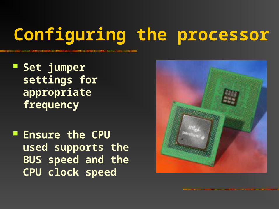
Configuring the processor
Set jumper settings for appropriate frequency
Ensure the CPU used supports the BUS speed and the CPU clock speed
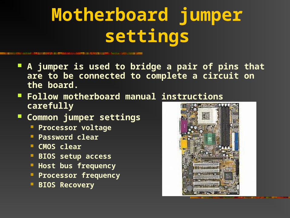
Motherboard jumper settings
A jumper is used to bridge a pair of pins that are to be connected to complete a circuit on the board.
Follow motherboard manual instructions carefully Common jumper settings
Processor voltage Password clear CMOS clear BIOS setup access Host bus frequency Processor frequency BIOS Recovery
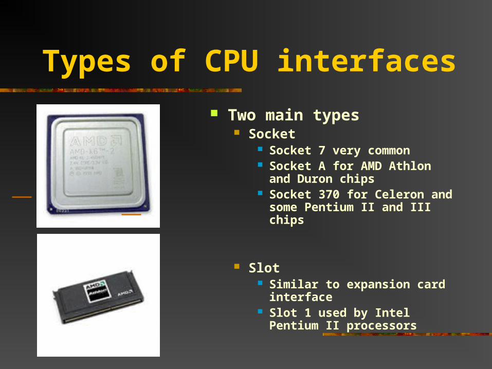
Types of CPU interfaces
Two main types Socket
Socket 7 very common Socket A for AMD Athlon and
Duron chips Socket 370 for Celeron and
some Pentium II and III chips
Slot Similar to expansion card
interface Slot 1 used by Intel Pentium II
processors
Installing the CPU
ZIF (Zero Insertion Force) trait on nearly all socket 7 and similar types
Inspect pins for damage Locate pin 1 on both chip and socket Open the ZIF socket (raise lever) Insert processor (should easily slide on) Make sure there is not a gap between bottom of chip and
socket Push lever down Set CPU voltage jumper settings if necessary (Pentium II
and later CPU’s adjust automatically to voltage)
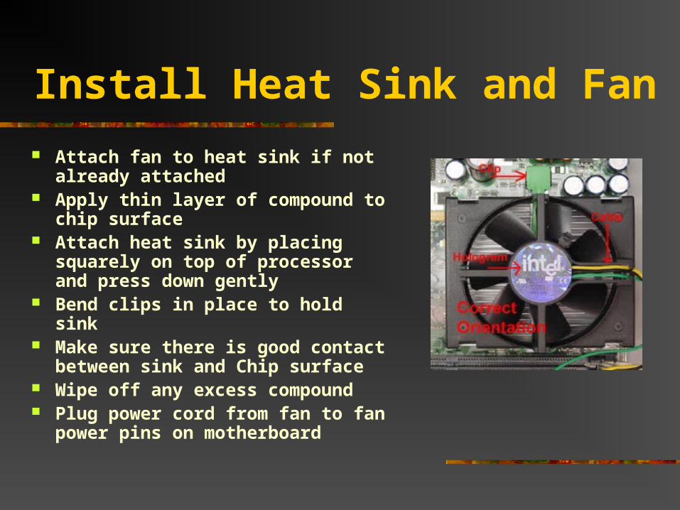
Install Heat Sink and Fan
Attach fan to heat sink if not already attached
Apply thin layer of compound to chip surface
Attach heat sink by placing squarely on top of processor and press down gently
Bend clips in place to hold sink Make sure there is good contact
between sink and Chip surface Wipe off any excess compound Plug power cord from fan to fan
power pins on motherboard
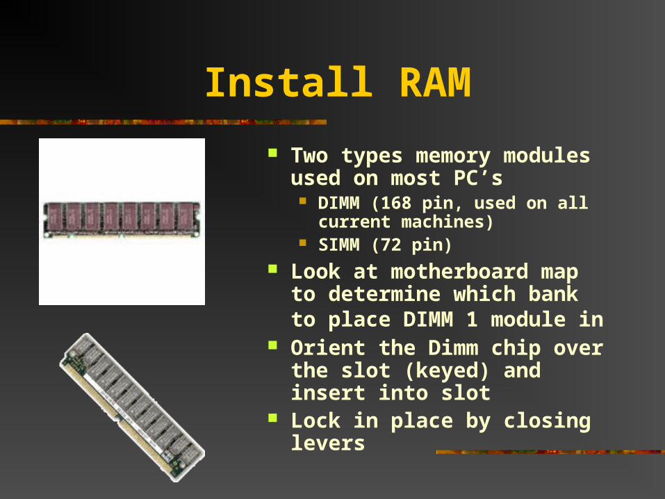
Install RAM
Two types memory modules used on most PC’s DIMM (168 pin, used on all
current machines) SIMM (72 pin)
Look at motherboard map to determine which bank to place DIMM 1 module in
Orient the Dimm chip over the slot (keyed) and insert into slot
Lock in place by closing levers
Installing the Motherboard
Position case for easy access, locate holes on motherboard and corresponding holes on case
Insert spacers that came with motherboard into holes on case and install plastic standoffs into holes on motherboard
Carefully slide the board into the case, lining up holes Tighten board to case with screws Verify that the back of the motherboard is not
touching the case, all slots and connectors line up properly, board is securely held in place, and board does not bend when pressed
Attaching LEDs, keylock and speaker
Use motherboard manual as a guide for proper placement Turbo LED (mainly legacy item) Power LED Hard drive activity LED Keylock switch (common with older
systems, rare now; prevented BIOS meddling)
PC speaker
Connect power supply cables
AT motherboard Locate two large wire leads from power supply
(P8 and P9) Locate 12 pin power connector on motherboard Plug P8 and P9 into connector Be sure black wires are in the middle beside one
another ATX motherboard
Attach the connector that is keyed to fit only one way into the motherboard connector
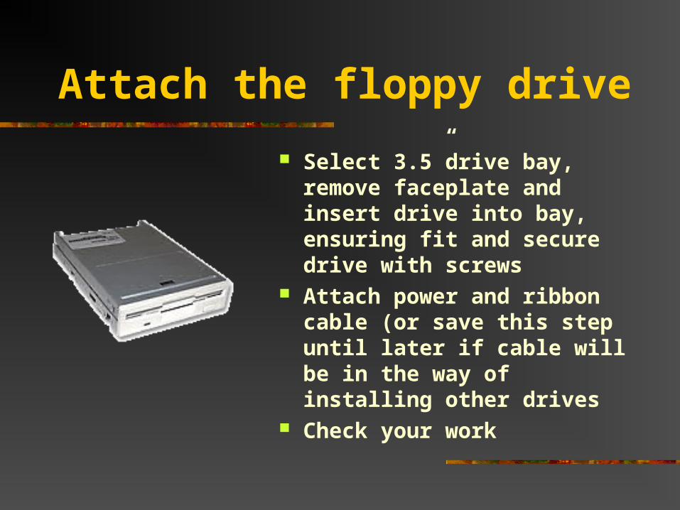
Attach the floppy drive
Select 3.5”drive bay, remove faceplate and insert drive into bay, ensuring fit and secure drive with screws
Attach power and ribbon cable (or save this step until later if cable will be in the way of installing other drives
Check your work
Attach hard drive and CD-ROM
Use separate IDE cables if possible and set both jumpers to Master (or single on the hard drive if available)
If sharing an IDE cable, set the hard drive to Master and the CD-ROM to slave
Install hard drive away from power supply which can act like a magnet and destroy data
Keep hard drive near front of case to benefit from air drawn into case and keep away from other hardware
Slide drive into selected drive rail and screw drive into place Attach ribbon cable to the primary controller of the motherboard
and attach power cord Follow with CD-ROM installation and attach to secondary
controller of the motherboard
Attaching ribbon cables
Usually, red stripe on cable indicates pin 1 Usually pin 1 on floppy data connectors is closest to
the power connector If two floppy drives are on one cable, drive A is
configured on the end connector and drive B is configured on the middle connector. Drive A is used for just one floppy drive.
Floppy drive IDE is 34 pin HDD and CD-ROM IDE cables are typically 40 pins
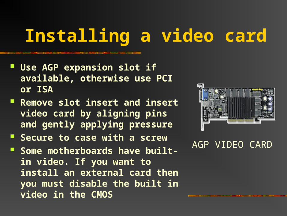
Installing a video card
Use AGP expansion slot if available, otherwise use PCI or ISA
Remove slot insert and insert video card by aligning pins and gently applying pressure
Secure to case with a screw Some motherboards have built-in
video. If you want to install an external card then you must disable the built in video in the CMOS
AGP VIDEO CARD
Post Assembly Checklist
All expansion cards are fully inserted CPU fan is attached to power The 110/220 volt switch is configured properly Drives are connected to power Ribbon cables are attached correctly Fans are free from interference from wires CPU voltage settings are correctly configured Power switch is off and power supply connectors are
connected properly to motherboard All connections are tight Pins are properly aligned Close the case before booting Connect keyboard, mouse and monitor and plug in AC power
cord
Booting the system
BIOS = Basic Input Output System Embedded in ROM chip on motherboard Contains program code required to control
all basic operating components of the system
Contains software needed to test the hardware and load the O.S.
Entering the BIOS configuration
Follow the prompt early in the startup process (usually strike the “delete” key or “cntrl-alt-del”) to access the CMOS Setup utility.
Enter date and time Set hard disks fields to “auto” to allow BIOS to
auto detect and configure the hard drives Make sure that the floppy drive and the video
card are detected Program Halt On to “all errors” so that error
problems can be reported before they corrupt data.
BIOS and Chipset Features setup screens
BIOS Features Place where system
hardware can be fine tuned for optimal performance
Set up boot sequence
Chipset Features Auto Configuration
should be set to “Enabled”
Power Management and PnP/PCI setup
Power Management Feature settings control
the computer’s optional power management for devices
Recommended to disable the choice “power management” as when enabled, devices can be put into sleep mode, but some software applications and OS may not recognize the devices in this mode
Plug n Play Default settings should
be used when working on newer systems because any manual configurations require a good knowledge of the bus devices installed.
If any conflicts occur, the “reset configuration data” feature will clear this portion of the BIOS setup and return it to defaults upon reboot
Integrated Peripherals and Fixed disk detection screens
Integrated Peripherals Includes devices such as
floppy and hard drive controllers, USB controller, serial and parallel ports, sound card chip
Set these features to “auto”to permit the BIOS to issue for example, the appropriate IDE drive commands to determine what mode the hard drives will support
Fixed Disk Detection In the event that the “Hard
Disks AUTP setting” in the CMOS setup screen is not automatically detecting the hard drive’s geometry, the Fixed Disk Detection will allow the manual running of the IDE auto detection program and select the auto detection for each drive on the controller channel. The BIOS will scan and report drive parameters which can then be accepted or rejected.
Passwords screens and the load setup defaults screen Passwords screens
User password Allows the installation
of a password that will keep the system from booting unless the password is entered
Prevents access to the BIOS
Supervisor password Usually found in large
institutions Once set, the BIOS
setups are locked with a master password
Load Setup Defaults Screen Resets the BIOS setup to
default settings Will not affect the
settings in the standard CMOS Setup screen
Can be used when configuring the system for the first time and problems are encountered.
BIOS EXIT OPTIONS
Exit without saving setup
Save and exit setup Computer will restart
with new configuration
POST errors, troubleshooting
POST routine ensures that all the hardware the system needs for startup is there and that everything is functioning properly before the boot process begins
Post error codes take the form of a series of beeps that identify a faulty hardware component.
If the new system is functioning normally, one short beep will usually be heard at the completion of POST.
Troubleshooting POST continued
POST typically provides three types of output messages: audio codes (beeps), onscreen text messages, and hexadecimal numeric codes that are sent to an I/O port address.
POST generally continues past non-fatal problems, but fatal problems cause POST to halt the boot process. If problems occur early, before any drivers are loaded for the monitor, for example, then POST can only signal that a problem exists using beeps.
If the POST and the boot sequence can advance up to a point where the system can use the system video to display messages, then a message can be displayed on the screen. The message indicates what problems occurred and the probable cause. These are referred to as visual error codes. These error messages are usually in the form of a numeric code, for example, 1790-Disk 0 Error.