ASSA’s e-CALLISTO Front End Electronics Package RFI Sources
9
ASSA’s e-CALLISTO Front End Electronics Package In the previous article “ASSA’s Antenna”, the reader hopefully took away with them that the Log Periodic Dipole Array (LPDA) was a wide bandwidth antenna and not a high gain antenna. It’s not really possible to have both of these characteristics in a simple antenna structure. It is possible to compensate for this lack of sensitivity by the use of low loss cables, a minimal number of protection devices and the careful addition of low noise figure (NF) amplification between the LPDA and the Callisto Receiver (Rx). For the purpose of this document, I’ll call this collection of items the Front End Electronics Package (FEEP). It is very important to maintain the NF of the receiver system as low as possible. The ultimate sensitivity of the receiver system is largely determined by the NF of the receiver system. RFI Sources Local sources of radio frequency interference (RFI) may adversely effect the effective sensitivity of any Callisto intallation. The following list of in-band sources of RFI is not exhaustive, but would probably account for the majority of forseeable (consistent) problems that may be encountered onsite at Sunnydale. • 52kW FM broadcasts (88MHz to 108MHz) from Crafers, 93km to the West South West • 50kW VHF DTV broadcasts (177MHz to 227MHz) from Crafers, 93km to the West South West • UHF DTV broadcasts (564.5MHz) from Crafers, 93km to West South West • 210W UHF DTV broadcasts (620MHz to 649MHz) from Mannum, 41km to the South West • 75W UHF DTV broadcasts (571MHz to 607MHz) from Punyelroo, 9km to the North • Telstra 3G (850MHz) and 4G (700MHz) from Walkers Flat, 10.5km to the South • Optus 3G (900MHz) and 4G (700MHz) from Caurnamont, 18.5km to the South South West • Telstra 3G (850MHz) and 4G (700MHz) from Caurnamont, 18.5km to the South South West • Optus 3G (900MHz) and 4G (700MHz) from Black Hill, 19.5km to the West • Telstra 3G (850MHz) and 4G (700MHz) from Black Hill, 18.5km to the West • Optus 3G (900MHz) and 4G (700MHz) from Swan Reach, 20km to the North • Telstra 3G (850MHz) and 4G (700MHz) from Swan Reach, approx. 20km to the North FEEP Design In the following block diagrams, I will show the LPDA, Callisto Rx and +12VDC Power Supply and the component parts of the FEEP. A Lightning Protection Device, a combination of Low Noise Amplifier(s) (LNA), Bias-Tees and various interconnecting coaxial cables. The first block diagram identifies each of the component parts and their order in the radio frequency (RF) path. Where possible, coaxial cables are kept to a minimal length and components are located as close as possible to reduce losses, particularly prior to the first LNA. The attenuation (losses) introduced between the LPDA and the first LNA, combined with the NF of the first LNA, largely determine the NF of the receiver system so it is very important to minimise these losses, if possible. The lowest NF LNA that I was able to find was based on the Mini-Circuits PGA-103+ E-PHEMT device and this will be used as the first LNA device. Another characteristic of concern is the frequency response of this device, which rolls off dramatically from 300MHz upward. For the purposes of this document, specifications and estimates will be stated at 500MHz but it should be noted that there will be different figures applicable, above and below this frequency. In our Callisto application, the lowest loss flexible coaxial cable that would physically fit inside the the boom diameter of LPDA was chosen and the shortest practical length used. It is approximately 5 metres from the LPDA feedpoint down to the lightning protector input. In order to optimise the gain and dynamic range of the Callisto receiver system, several prototype FEEPs with different gains were built and tested for suitability.
Transcript of ASSA’s e-CALLISTO Front End Electronics Package RFI Sources

ASSA’s e-CALLISTO Front End Electronics Package
In the previous article “ASSA’s Antenna”, the reader hopefully took away with them that the Log Periodic Dipole Array (LPDA) was a wide bandwidth antenna and not a high gain antenna. It’s not really possible tohave both of these characteristics in a simple antenna structure. It is possible to compensate for this lack of sensitivity by the use of low loss cables, a minimal number of protection devices and the careful additionof low noise figure (NF) amplification between the LPDA and the Callisto Receiver (Rx).
For the purpose of this document, I’ll call this collection of items the Front End Electronics Package (FEEP). It is very important to maintain the NF of the receiver system as low as possible. The ultimate sensitivity of the receiver system is largely determined by the NF of the receiver system.
RFI Sources
Local sources of radio frequency interference (RFI) may adversely effect the effective sensitivity of any Callisto intallation. The following list of in-band sources of RFI is not exhaustive, but would probably account for the majority of forseeable (consistent) problems that may be encountered onsite at Sunnydale.
• 52kW FM broadcasts (88MHz to 108MHz) from Crafers, 93km to the West South West
• 50kW VHF DTV broadcasts (177MHz to 227MHz) from Crafers, 93km to the West South West
• UHF DTV broadcasts (564.5MHz) from Crafers, 93km to West South West
• 210W UHF DTV broadcasts (620MHz to 649MHz) from Mannum, 41km to the South West
• 75W UHF DTV broadcasts (571MHz to 607MHz) from Punyelroo, 9km to the North
• Telstra 3G (850MHz) and 4G (700MHz) from Walkers Flat, 10.5km to the South
• Optus 3G (900MHz) and 4G (700MHz) from Caurnamont, 18.5km to the South South West
• Telstra 3G (850MHz) and 4G (700MHz) from Caurnamont, 18.5km to the South South West
• Optus 3G (900MHz) and 4G (700MHz) from Black Hill, 19.5km to the West
• Telstra 3G (850MHz) and 4G (700MHz) from Black Hill, 18.5km to the West
• Optus 3G (900MHz) and 4G (700MHz) from Swan Reach, 20km to the North
• Telstra 3G (850MHz) and 4G (700MHz) from Swan Reach, approx. 20km to the North
FEEP Design
In the following block diagrams, I will show the LPDA, Callisto Rx and +12VDC Power Supply and the component parts of the FEEP. A Lightning Protection Device, a combination of Low Noise Amplifier(s) (LNA), Bias-Tees and various interconnecting coaxial cables. The first block diagram identifies each of the component parts and their order in the radio frequency (RF) path.
Where possible, coaxial cables are kept to a minimal length and components are located as close as possible to reduce losses, particularly prior to the first LNA. The attenuation (losses) introduced between the LPDA and the first LNA, combined with the NF of the first LNA, largely determine the NF of the receiver system so it is very important to minimise these losses, if possible.
The lowest NF LNA that I was able to find was based on the Mini-Circuits PGA-103+ E-PHEMT device and this will be used as the first LNA device. Another characteristic of concern is the frequency response of this device, which rolls off dramatically from 300MHz upward. For the purposes of this document, specifications and estimates will be stated at 500MHz but it should be noted that there will be different figures applicable, above and below this frequency.
In our Callisto application, the lowest loss flexible coaxial cable that would physically fit inside the the boomdiameter of LPDA was chosen and the shortest practical length used. It is approximately 5 metres from the LPDA feedpoint down to the lightning protector input.
In order to optimise the gain and dynamic range of the Callisto receiver system, several prototype FEEPs with different gains were built and tested for suitability.

+20dB Gain Prototype
The 500MHz gain of the PGA-103 is approx. +20dB, so this prototype is basically the lightning protector, asingle LNA with no output attenuation and a Bias-Tee to supply DC power to the LNA.
While this basic system is probably suitable for the task, it has two important limitations:
• it can’t easily be optimised further.What might be a suitable gain configuration for one or a number of sites may not be suitable for oursite. Some flexibility should be available to allow increases or decreases of gain, if necessary or desirable.
• it requires premium coaxial componentry to maintain it’s nominal performance specification.High performance cables generally require large bend radii and have limited and often expensive connector options. The ability to add gain where necessary to compensate for smaller but lossier coaxial cable, components and connectors is a handy facility to have.
This configuration is the closest to the version that is suggested by the Project PI
The interconnecting cables between the lightning protector output, the LNA and the Bias Tee are various lengths of 0.141” hand formable semi-rigid coaxial cable fitted with SMA plugs. There is a 3.5m (approx.) length of flexible coaxial cable between the two Bias-Tees, which are required to pass +12VDC along the coaxial cable to power the LNA. This flexible coax. is a high quality, low loss cable which complements thechoice of components used closer to the LPDA . Finally there is a short flexible coaxial cable connecting the Callisto Rx to the Bias Tee.
+20dB Prototype Block Diagram

+20dB Prototype FEEP

+50dB Gain Prototype
This prototype was my original configuration choice and comprises the lightning protector, a PGA-103+ LNA with no output attenuation, a second LNA with a 500MHz gain specification of approx. +30dB and a Bias Tee to supply DC power to both of the LNAs.
This high gain system is not really suitable for the task, it has several important limitations:
• while we can decrease the gain of the system, the change is probably at the wrong point.Unlike the Mini-Kits PGA-103 LNA, the RF Bay LNA-1030 does not have the flexibility of being able to attenuate it’s output, an external two port device would need to be used. Space limitationswithin our enclosure make this difficult. By decreasing the gain of the first LNA, we increase the NF of the system. It would be better to be able to change the gain of both LNAs to optimise the inevitable trade off between minimal NF and maximum dynamic range.
• DC power consumptionThe PGA-103 LNA consumes approx. 90mA in a 12VDC power system and the LNA-1030 consumes approx. 140mA. This current load exceeds the 160mA specification for the Mini-Kits EME181A70 Bias Tee.
The interconnecting cables between the lightning protector output, the first LNA, the second LNA and the Bias Tee are 100mm lengths of 0.141” hand formable semi-rigid coaxial cable with SMA plugs. The 100mm lengths are necessary to compensate for connector height and angular differences on each LNA enclosure. There is a 3.5m (approx.) length of flexible coaxial cable between the two Bias Tees, which arerequired to pass +12VDC along the coaxial cable to power the two LNAs. This flexible coax. is a medium quality, low loss cable which complements the choice of components used closer to the LPDA . Finally there is a short flexible coaxial cable connecting the Callisto Rx to the Bias Tee.
+50dB Prototype Block Diagram

+50dB Prototype FEEP
+25dB Gain Prototype
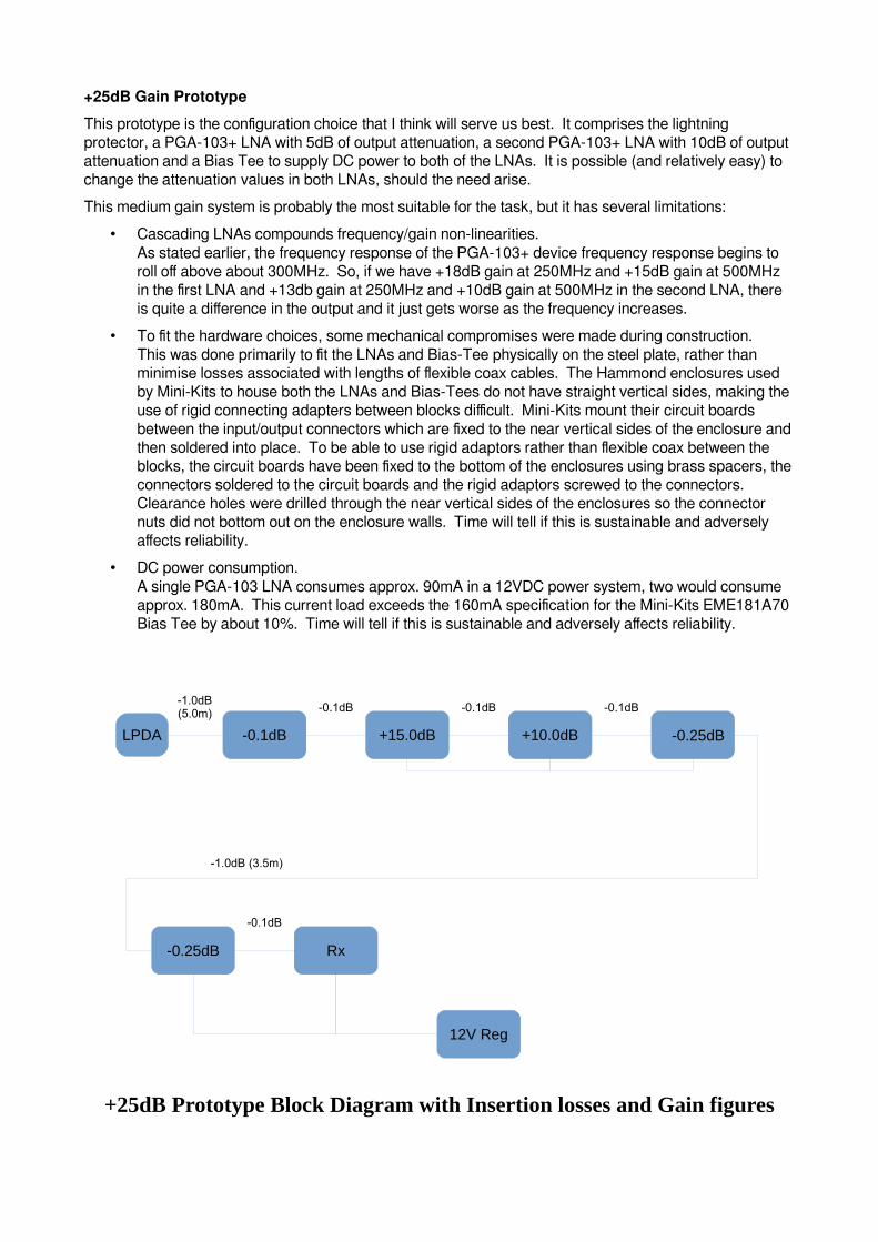
This prototype is the configuration choice that I think will serve us best. It comprises the lightning protector, a PGA-103+ LNA with 5dB of output attenuation, a second PGA-103+ LNA with 10dB of output attenuation and a Bias Tee to supply DC power to both of the LNAs. It is possible (and relatively easy) to change the attenuation values in both LNAs, should the need arise.
This medium gain system is probably the most suitable for the task, but it has several limitations:
• Cascading LNAs compounds frequency/gain non-linearities.As stated earlier, the frequency response of the PGA-103+ device frequency response begins to roll off above about 300MHz. So, if we have +18dB gain at 250MHz and +15dB gain at 500MHz in the first LNA and +13db gain at 250MHz and +10dB gain at 500MHz in the second LNA, there is quite a difference in the output and it just gets worse as the frequency increases.
• To fit the hardware choices, some mechanical compromises were made during construction.This was done primarily to fit the LNAs and Bias-Tee physically on the steel plate, rather than minimise losses associated with lengths of flexible coax cables. The Hammond enclosures used by Mini-Kits to house both the LNAs and Bias-Tees do not have straight vertical sides, making the use of rigid connecting adapters between blocks difficult. Mini-Kits mount their circuit boards between the input/output connectors which are fixed to the near vertical sides of the enclosure andthen soldered into place. To be able to use rigid adaptors rather than flexible coax between the blocks, the circuit boards have been fixed to the bottom of the enclosures using brass spacers, theconnectors soldered to the circuit boards and the rigid adaptors screwed to the connectors. Clearance holes were drilled through the near vertical sides of the enclosures so the connector nuts did not bottom out on the enclosure walls. Time will tell if this is sustainable and adversely affects reliability.
• DC power consumption.A single PGA-103 LNA consumes approx. 90mA in a 12VDC power system, two would consume approx. 180mA. This current load exceeds the 160mA specification for the Mini-Kits EME181A70 Bias Tee by about 10%. Time will tell if this is sustainable and adversely affects reliability.
-0.1dB +15.0dB +10.0dB
-0.1dB -0.1dB-1.0dB(5.0m) -0.1dB
-0.25dB
-0.25dB Rx
-0.1dB
-1.0dB (3.5m)
12V Reg
LPDA
+25dB Prototype Block Diagram with Insertion losses and Gain figures
The interconnecting cables between the lightning protector output and the first LNA is a 110mm length of 0.141” hand formable semi-rigid coaxial cable with SMA plugs. There is a 3.5m (approx.) length of flexiblecoaxial cable between the two Bias Tees, which are required to pass +12VDC along the coaxial cable to power the two LNAs. This flexible coax. is a medium quality, low loss cable which complements the choiceof components used closer to the LPDA . Finally there is a short flexible coaxial cable connecting the Callisto Rx to the Bias Tee.
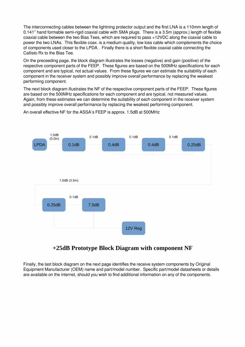
On the preceeding page, the block diagram illustrates the losses (negative) and gain (positive) of the respective component parts of the FEEP. These figures are based on the 500MHz specifications for each component and are typical, not actual values. From these figures we can estimate the suitability of each component in the receiver system and possibly improve overall performance by replacing the weakest performing component.
The next block diagram illustrates the NF of the respective component parts of the FEEP. These figures are based on the 500MHz specifications for each component and are typical, not measured values. Again, from these estimates we can determine the suitability of each component in the receiver system and possibly improve overall performance by replacing the weakest performing component.
An overall effective NF for the ASSA’s FEEP is approx. 1.5dB at 500MHz
0.1dB 0.4dB 0.4dB
0.1dB 0.1dB1.0dB(5.0m) 0.1dB
0.25dB
0.25dB 7.5dB
0.1dB
1.0dB (3.5m)
12V Reg
LPDA
+25dB Prototype Block Diagram with component NF
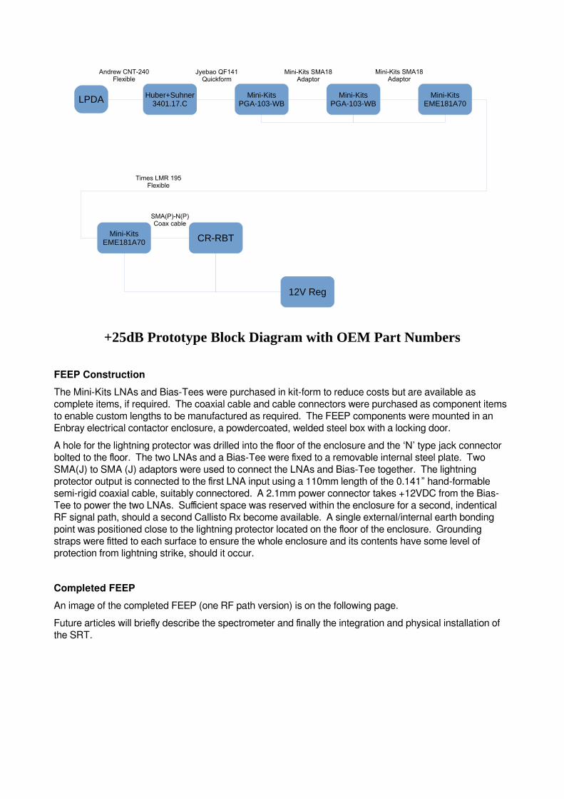
Finally, the last block diagram on the next page identifies the receive system components by Original Equipment Manufacturer (OEM) name and part/model number. Specific part/model datasheets or details are available on the internet, should you wish to find additional information on any of the components.
Huber+Suhner3401.17.C
Mini-KitsPGA-103-WB
Mini-KitsPGA-103-WB
Jyebao QF141Quickform
Mini-Kits SMA18 Adaptor
Andrew CNT-240Flexible
Mini-KitsEME181A70
Mini-Kits SMA18 Adaptor
Mini-KitsEME181A70 CR-RBT
SMA(P)-N(P)Coax cable
Times LMR 195 Flexible
12V Reg
LPDA
+25dB Prototype Block Diagram with OEM Part Numbers
FEEP Construction
The Mini-Kits LNAs and Bias-Tees were purchased in kit-form to reduce costs but are available as complete items, if required. The coaxial cable and cable connectors were purchased as component items to enable custom lengths to be manufactured as required. The FEEP components were mounted in an Enbray electrical contactor enclosure, a powdercoated, welded steel box with a locking door.
A hole for the lightning protector was drilled into the floor of the enclosure and the ‘N’ type jack connector bolted to the floor. The two LNAs and a Bias-Tee were fixed to a removable internal steel plate. Two SMA(J) to SMA (J) adaptors were used to connect the LNAs and Bias-Tee together. The lightning protector output is connected to the first LNA input using a 110mm length of the 0.141” hand-formable semi-rigid coaxial cable, suitably connectored. A 2.1mm power connector takes +12VDC from the Bias-Tee to power the two LNAs. Sufficient space was reserved within the enclosure for a second, indentical RF signal path, should a second Callisto Rx become available. A single external/internal earth bonding point was positioned close to the lightning protector located on the floor of the enclosure. Grounding straps were fitted to each surface to ensure the whole enclosure and its contents have some level of protection from lightning strike, should it occur.
Completed FEEP
An image of the completed FEEP (one RF path version) is on the following page.
Future articles will briefly describe the spectrometer and finally the integration and physical installation of the SRT.
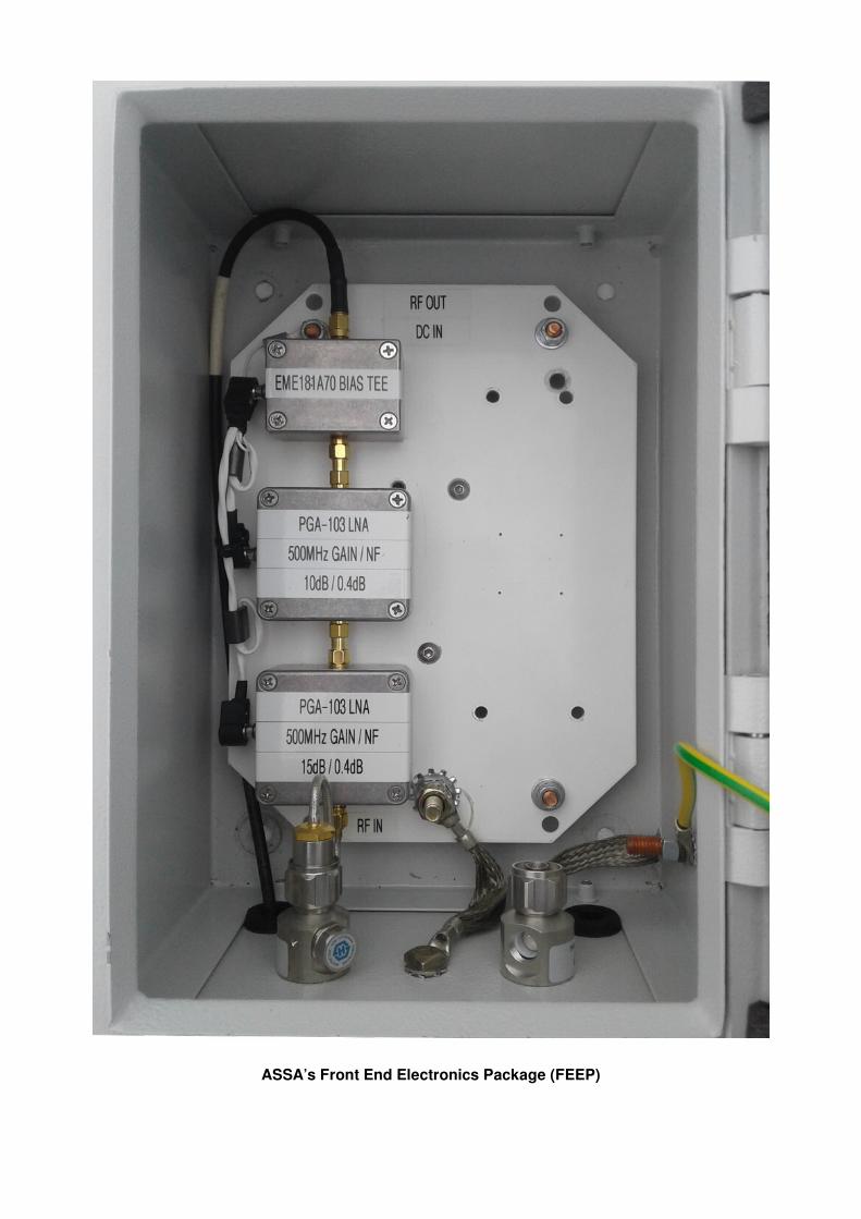
ASSA’s Front End Electronics Package (FEEP)