Aspects of VDSL Evolution
23
DSL Forum Technical Report TR-040 (Formerly WT-047v8) Aspects of VDSL Evolution June 2001 Abstract: This document provides a framework for VDSL study within the DSL Forum. It points to the standards which define VDSL requirements and interfaces. It also identifies deployment scenarios that are expected to be implemented and characterizes the service evolution from other DSL technologies to those based on VDSL. Additionally, challenges to deployment are considered. Notice: © 2001 Digital Subscriber Line Forum. All Rights Reserved. DSL Forum documents may be copied, downloaded, stored on a server or otherwise redistributed in their entirety only. Notwithstanding anything to the contrary, DSL Forum makes no representation or warranty, expressed or implied, concerning this publication, its contents or the completeness, accuracy, or applicability of any information contained in this publication. No liability of any kind shall be assumed by DSL Forum as a result of reliance upon any information contained in this publication. DSL Forum does not assume any responsibility to update or correct any information in this publication. The receipt or any use of this document or its contents does not in any way create by implication or otherwise any express or implied license or right to or under any patent, copyright, trademark or trade secret rights which are or may be associated with the ideas, techniques, concepts or expressions contained herein.
Transcript of Aspects of VDSL Evolution
DSL ForumTechnical Report
TR-040(Formerly WT-047v8)
Aspects of VDSL Evolution
June 2001
Abstract:This document provides a framework for VDSL study within the DSL Forum. It points to the standardswhich define VDSL requirements and interfaces. It also identifies deployment scenarios that are expectedto be implemented and characterizes the service evolution from other DSL technologies to those based onVDSL. Additionally, challenges to deployment are considered.
Notice: © 2001 Digital Subscriber Line Forum. All Rights Reserved.DSL Forum documents may be copied, downloaded, stored on a server or otherwiseredistributed in their entirety only.Notwithstanding anything to the contrary, DSL Forum makes no representation orwarranty, expressed or implied, concerning this publication, its contents or thecompleteness, accuracy, or applicability of any information contained in this publication.No liability of any kind shall be assumed by DSL Forum as a result of reliance upon anyinformation contained in this publication. DSL Forum does not assume any responsibilityto update or correct any information in this publication.The receipt or any use of this document or its contents does not in any way create byimplication or otherwise any express or implied license or right to or under any patent,copyright, trademark or trade secret rights which are or may be associated with the ideas,techniques, concepts or expressions contained herein.
Aspects of VDSL Evolution DSL Forum TR-040
2
1 INTRODUCTION ................................................................................................................................ 3
2 REFERENCES ..................................................................................................................................... 3
3 GLOSSARY .......................................................................................................................................... 3
4 WHAT IS VDSL................................................................................................................................... 4
4.1 WHERE WILL VDSL BE USED.......................................................................................................... 44.2 WHY WILL VDSL BE USED.............................................................................................................. 5
5 VDSL STANDARDIZATION ............................................................................................................. 5
5.1 STATUS............................................................................................................................................ 65.1.1 Technology ............................................................................................................................. 65.1.2 Regulatory .............................................................................................................................. 75.1.3 Interoperability....................................................................................................................... 8
5.2 BACKGROUND TO STANDARDIZATION EFFORTS.............................................................................. 8
6 VDSL SERVICE CHARACTERISTICS ......................................................................................... 10
6.1 VDSL REQUIREMENTS.................................................................................................................. 106.2 VDSL CHARACTERISTICS ............................................................................................................. 10
6.2.1 Rate versus Reach................................................................................................................. 106.2.2 Bit Error Ratio...................................................................................................................... 116.2.3 Latency ................................................................................................................................. 116.2.4 Spectral Compatibility .......................................................................................................... 11
7 SERVICE EVOLUTION TO VDSL................................................................................................. 12
7.1 SERVICE MIGRATION..................................................................................................................... 127.2 SERVICE EVOLUTION ON GREEN FIELD SITES ............................................................................... 12
7.2.1 Factors enabling VDSL Service on Green Field Sites.......................................................... 137.2.2 Challenges to VDSL Service on Green Field Sites ............................................................... 13
7.3 SERVICE EVOLUTION ON EXISTING PLANT .................................................................................... 137.3.1 Factors enabling VDSL Service on Existing Plant ............................................................... 147.3.2 Challenges to VDSL Service on Existing Plant .................................................................... 14
7.4 TWO STAGE EVOLUTION OF VDSL SERVICES ............................................................................... 147.5 VDSL ENABLED SERVICES ........................................................................................................... 14
8 DEPLOYMENT SCENARIOS ......................................................................................................... 15
8.1 EXAMPLE DEPLOYMENTS.............................................................................................................. 158.1.1 Public Broadband Access Networks ..................................................................................... 158.1.2 Campus Environment ........................................................................................................... 168.1.3 Multi-tenant Environment..................................................................................................... 178.1.4 Home Networking ................................................................................................................. 19
8.2 NETWORK TOPOLOGIES................................................................................................................. 198.2.1 Star Networks ....................................................................................................................... 208.2.2 Point-to-Point ....................................................................................................................... 208.2.3 Mesh Networks ..................................................................................................................... 20
9 REGULATORY BARRIERS AND RELATED ISSUES................................................................ 20
9.1 UNBUNDLING ................................................................................................................................ 209.2 EMC ............................................................................................................................................. 209.3 RF INGRESS AND EGRESS FROM UNSHIELDED WIRE..................................................................... 219.4 UNREGULATED INTERFERENCE ISSUES .......................................................................................... 22
Aspects of VDSL Evolution DSL Forum TR-040
3
1 IntroductionThis document provides a framework for VDSL study within the DSL Forum. It points to the standardswhich define VDSL requirements and interfaces. It also identifies deployment scenarios, utilizing thepublic network, that are expected to be implemented and characterizes the service evolution from otherDSL technologies to those based on VDSL. Additionally, challenges to deployment are considered. VDSLapplications utilizing private networks are outside the scope of this document.
2 ReferencesAt the time of publication, the editions indicated were valid. All references are subject to revision.
[1] Committee T1 Working Group Contribution T1E1.4/2000-009R3 (LB941) “Very-high-bit-rate DigitalSubscriber Line (VDSL) Metallic Interface, Part 1: Functional Requirements and CommonSpecification”, November 2000
[2] Committee T1 Working Group Contribution T1E1.4/2000-011R3 (LB941) “VDSL TechnicalSpecification, Part 2: Technical Specification for a Single-Carrier Modulation (SCM) Transceiver”,November 2000
[3] Committee T1 Working Group Contribution T1E1.4/2000-013R4 (LB941) “Very-high bit-rate DigitalSubscriber Lines (VDSL) Metallic Interface, Part 3: Technical Specification of a Multi-CarrierModulation (MCM) Transceiver”, November 2000
[4] ETSI TS 101 270-1 Ver. 1.2.1 “Transmission and Multiplexing (TM); Access transmission systems onmetallic access cables; Very high speed Digital Subscriber Line (VDSL); Part 1: Functionalrequirements”, 1999-10
[5] ETSI TS 101 270-2 Ver. 1.1.1 “Transmission and Multiplexing (TM); Access transmission systems onmetallic access cables; Very high speed Digital Subscriber Line (VDSL); Part 2: Transceiverspecification”, 2001-02
[6] FSAN Full Services Access Network Requirements Specification Issue 3, 1998-08-18[7] Radiocommunications Agency draft MPT 1570 “Radiation Limits and Measurement Standard,
Electromagnetic radiation from telecommunications systems operating over material substances in thefrequency range 9 kHz to 300 MHz”, April 2000
[8] Federal Communications Commission, Code of Federal Regulations, Title 47 Telecommunications Part15, “Radio Frequency Devices”
[9] Federal Communications Commission, Code of Federal Regulations, Title 47 Telecommunication Part68, “Connection of terminal equipment to the telephone network”
[10] CENELEC, EN55022, “Information Technology Equipment – Radio disturbance characteristics -Limits and methods of measurement”
[11] Committee T1, T1.417-2001, “Spectrum Management For Loop Transmissions Systems”
3 GlossaryThe following definitions/abbreviations apply for the purposes of this document:
ANSI American National Standards InstituteCENELEC European Committee for Electrotechnical StandardizationCO Central OfficeCLEC Competitive Local Exchange CarrierCPE Customer Premises EquipmentDAVIC Digital Audio Video CouncilDLC Digital Loop CarrierDSL Digital Subscriber LineDSLAM DSL Access MultiplexerETSI European Telecommunications Standards InstituteFSAN Full Service Access NetworkFS-VDSL Full Service VDSLFTTB Fiber-to-the-business

Aspects of VDSL Evolution DSL Forum TR-040
4
FTTC Fiber-to-the-curbFTTCab Fiber-to-the-CabinetFTTH Fiber-to-the-homeG.pnt The working title given to the family of phone line networking recommendations being
developed by the ITU-T. The first recommendation to be published, G.989.1 PhonelineNetworking Transceivers - Foundation, specifies the basic characteristics of devicesdesigned for the transmission of data over in-premises phoneline networks
G.vdsl The working title given to the VDSL recommendation being developed by the ITU-TILEC Incumbent Local Exchange CarrierISO/IECJTC
In the field of information technology, ISO (the International Organization forStandardization) and IEC (the International Electrotechnical Commission) have establisheda joint technical committee, ISO/IEC JTC
ITU-T International Telecommunication Union, Telecommunication Standardization SectorNGDLC Next-Generation DLCMCM Multi-Carrier Modulation – a candidate line code for VDSL employing multiple carriers
(i.e. DMT)MDU Multi-Dwelling Unit (typically a residence)MPEG Motion Pictures Expert GroupMTU Multi-Tenant Unit (typically a business)ONU Optical Networking UnitPON Passive Optical NetworkPOTS Plain Old Telephone ServiceSCM Single-Carrier Modulation – a candidate line code for VDSL employing a single carrier
(i.e. CAP/QAM)SG15/Q4 Study Group 15 / Question 4 – The working group of ITU-T responsible for Transport
networks, systems and equipment specifically addressing transceivers for subscriber accesssystems (eg. VDSL standards)
SME Small / Medium EnterpriseT1E1.4 Committee T1, technical subcommittee E1, working group 4 – The working group of
Committee T1 responsible for Digital Subscriber Loop Access (eg. VDSL standards)TM6 Transmission & Multiplexing 6 – The working group of ETSI responsible for Access
Networks (eg. VDSL standards)VDSL Very High Speed DSL or Very-high-bit-rate DSLVoDSL Voice over DSLVoIP Voice over IP
4 What is VDSLVDSL is a digital data transport technology which uses a copper wire pair as the physical medium and assuch is bounded by that medium. Both symmetric and asymmetric data flows are supported providingincreased flexibility in meeting specific applications. (See section 6 for general characteristics of VDSL.)
4.1 Where will VDSL be usedTraditionally, VDSL has been viewed as providing the “last mile” access to the home. Since VDSL enablesmuch higher bandwidths than established mass market DSL technologies like ISDN and ADSL it is usuallyassociated with the delivery of a bundle of services. Like existing xDSLs, VDSL can provide the familiarhigh speed internet access as well as voice services. Due to increased bandwidth availability VDSL can,however, provide higher speed internet access, more simultaneous voice channels and perhaps unique toVDSL, digitally encoded video. These video services typically consist of multiple channels of MPEGencoded data, today requiring from 6 to 8 Mbps for sequences with fast movements and good picturequality. At least two simultaneous video streams must be delivered in order to compete with the near videoon demand systems currently offered by cable TV Operators. This bundle of services drives the bandwidthrequirements for asymmetric VDSL to deliver at least 13 Mbps downstream and 1 Mbps upstream.
Several business applications are also possible and promise additional evolutionary growth where coppercan provide high speed pipes for access in a campus or high rise building environment. The re-use of

Aspects of VDSL Evolution DSL Forum TR-040
5
copper in business parks, campuses, multi-tenant buildings, etc enables VDSL to cost effectively servegrowing bandwidth needs where cable lengths fit VDSL topology. One significant symmetrical applicationis the extension of corporate ethernets which drives the requirement for symmetrical bandwidth of at least10 Mbps.
4.2 Why will VDSL be usedAs an “access technology” VDSL must be viewed in the context of other competing technologies such asFiber-to-the-Home(FTTH), Wireless local loop and even Power Line telecom. Viewed in this manner, theviability of VDSL is closely related to the following drivers:
− The commitment of the incumbent service provider (ILEC) to use the existing copper plant forapplications requiring VDSL bandwidths.− The competitive service provider (CLEC) commitment to the same thing in an unbundled loopenvironment.− The cost/benefit trade-offs of using a FTTCab technology such as VDSL over existing copper plantversus construction of an overlay architecture e.g., FTTH.
The primary driver for VDSL technology today is for residential access with a secondary goal of providinga business overlay. Much attention has been focused upon FTTH replacing copper-based technologies inthese applications. From a “bandwidth delivered” point of view fiber offers virtually unlimited bandwidthhowever installation costs currently favor architectures which reuse the existing copper plant. In the near-term a hybrid approach which pushes fiber closer to the customer (FTTCab or FTTC) which requires lessof the existing copper plant is most likely to prevail. VDSL offers data rates in excess of other DSLs and issufficient to address current broadband service requirements and therefore is likely to be the “last-mile”DSL of choice. This hybrid fiber-copper approach best satisfies the need for higher bandwidth serviceswhile minimizing expensive plant upgrades. As compression technologies progress over time the “limited”bandwidth of VDSL will not necessarily be a significant limitation versus fiber for many applications.
Another advantage of the VDSL architecture is the security benefit provided by point to point links. This isa significant advantage over technologies which rely upon a bus architecture, e.g. HFC networks.
5 VDSL StandardizationThere are currently three organizations developing VDSL transceiver standards; ITU-T, ETSI and ANSI(FSAN acts through contributions to these organizations).There are agreements between all of them topromote cooperation and to work towards the final standards with as few differences as possible. There aresome important differences in the goals between the different bodies, which results in differences betweenthem in focus and output (see 5.2 Background).
ITU (International Telecommunication Union) is the United Nations Specialized Agency in the field oftelecommunications. The ITU Telecommunication Standardization Sector (ITU-T) is a permanent organ ofthe ITU. The ITU-T is responsible for studying technical, operating and tariff questions and issuingRecommendations on them with a view to standardizing telecommunications on a worldwide basis. ITU-TRecommendation G.vdsl is being developed by Study Group 15 (Question 4).
ETSI (European Telecommunications Standards Institute) is a non-profit making organization whosemission is to produce the telecommunications standards that will be used for decades to come throughoutEurope and beyond. ETSI TM6 is responsible for VDSL.
ANSI (American National Standards Institute) has accredited Committee T1 to create networkinterconnections and interoperability standards for the United States. Committee T1, technicalsubcommittee E1, working group 4 is responsible for VDSL.

Aspects of VDSL Evolution DSL Forum TR-040
6
5.1 Status
5.1.1 TechnologyThis section provides a snapshot in time of the current status of the VDSL standardization effort within therespective standards organizations. The following information is believed to be accurate as of March 2001.A dual line code standard has been agreed for publishing by ETSI. Committee T1 is in the process ofresolving letter ballot comments for its dual line code trial use standard. ITU-T Study Group 15 continuesto progress its work towards publishing a VDSL recommendation.
5.1.1.1 ETSIETSI TM6 is in the process of developing a European VDSL specification which is currently composed oftwo parts;“Part 1: Functional requirements” is available in a second revision as ETSI Technical Specification TS 101270-1 ver 1.2.1.“Part 2: Transceiver specification” has been published as TS 101 270-2 ver 1.1.1.
The ETSITransceiver specification contains the description of two different Physical Media Dependent(PMD) layers, one based on Single-carrier Modulation and one based on Multi-carrier Modulation. Bothline codes use Frequency Division Duplexing (FDD) and a common set of frequency plans; frequency bandplan 997 and 998. The specified spectrums for use in this first version of the Transceiver specification isfrom 138kHz up to 12 MHz, with the use of the spectrum below and above for further study.
Outstanding issues associated with this specification include:- disposition of additional frequency band plans such as the Fx plan- specification of Upstream Power Back-Off (UPBO)
ETSI has started the following two new work items to address these issues and others;1. A revision of the VDSL Part 2 document.2. A study of VDSL services and assessment of the need for more bandwidth allocation.
5.1.1.2 ANSIANSI Accredited Standards Committee T1 T1E1 is in the process of developing a North AmericanVDSL specification which is currently composed of three parts;Part 1: which defines the VDSL functional requirements and specifications that are common to both Single-Carrier Modulation (SCM) and Multi-Carrier Modulation (MCM) based VDSL transceivers.Part 2: Technical Specification of a Single-Carrier Modulation (SCM) Transceiver.Part 3: Technical Specification of a Multi-Carrier Modulation (MCM) Transceiver.
Since consensus was not achieved on a single line code ANSI has decided to publish this draft Standard fortrial use, comment and criticism. It has been published in order to obtain those comments that will occur asa result of its use. When sufficient time has elapsed for the trial use of the Standard and subsequent receiptof comments (two years from the date of publication by Accredited Standards Committee T1), the draftstandard will be amended as needed, and a revised text will be submitted for approval as an AmericanNational Standard.
Part 1, Part 2 and Part 3 documents were agreed to be sent out for letter ballot from the November 2000meeting. The process of balloting and resolving letter ballot comments is now being performed before thedocuments can be officially published.
The T1E1.4 draft Trial Use Standard documents describe two different standard PMD layers and a thirdone is included in an informative Annex. One document is based on Single-carrier Modulation and theother one is based on Multi-carrier Modulation. The Multi-carrier document contains an informative Annexdescribing another Multi-carrier technology called Filtered Multi-tone (FMT).

Aspects of VDSL Evolution DSL Forum TR-040
7
All three line codes use FDD and a common frequency band plan, plan 998. Additionally, the use of theband between 25kHz and 138kHz is optional.
Outstanding issues associated with this specification include:- specification of Upstream Power Back-Off (UPBO)
5.1.1.3 ITU-TITU-T SG15/Q4 is in the process of developing an international VDSL Recommendation. The group’sstated target is to develop a single interoperable worldwide VDSL recommendation. Due primarily to alack of consensus on the line code issue, progress so far has been slow and little text has been produced forthe recommendation.
The following points highlight the status of agreements achieved by this group with respect to the VDSLrecommendation:- Both Single and Multi carrier line codes have been proposed but neither has achieved consensus.- Frequency Division Duplexing (FDD) will be used.- Three frequency band plans will be specified. Plan 997 and 998 are on equal footing while a third plan
called the Fx plan is “intended for use in Sweden only”. The use of the frequency band between 25kHzand 138kHz is also under study.
- Upstream Power Back-Off (UPBO) method has been agreed. The agreement calls for the upstreamtransmitter to limit its transmit power below a frequency dependent transmit mask. The shape of themask depends on the electrical length of the line over which the VDSL modem pair operates. Furtherdetails remain outstanding to completely specify UPBO.
5.1.2 RegulatoryThis section identifies the status of regulatory requirements that are known to apply to VDSL and arebelieved to be accurate as of December 2000. Service regulations are not currently addressed by thisdocument.
5.1.2.1 European CommunityEN55022 (www.cenelec.org) [10] is expected to be used by European regulators as guidelines forregulatory requirements. The intention of this standard is to establish uniform requirements for the radiodisturbance level of the equipment contained in the scope, to fix limits of disturbance, to describe methodsof measurement and to standardize operating conditions and interpretation of results. See section 9 forissues related to the application of this requirement.
A joint ETSI-CENELEC working group has been set up to look into in-situ measurements for radiatedemissions from installations.
At least two countries propose additional national regulations :
5.1.2.1.1 UKMPT 1570 Radiation Limits and Measurement Standard [7](http://www.radio.gov.uk/document/ra_info/ra107.htm) is expected to apply. It intends to afford generalprotection to licensed and license exempt radio communications services. Limits are defined for equipmentwhich operate over material substances (including metallic cable) in the frequency range from 9 kHz to 300MHz. These frequency ranges clearly overlap those used by VDSL systems. See section 9 for issues relatedto the application of this requirement.
5.1.2.1.2 GermanyRegTP documents (http://www.regtp.de/en/index.html) are expected to apply. The functions of the RegTPinclude ensuring efficient, interference-free use of frequencies while accommodating broadcastingrequirements. See section 9 for issues related to the application of this requirement.
Aspects of VDSL Evolution DSL Forum TR-040
8
5.1.2.2 United StatesFCC Part 68 (http://www.access.gpo.gov/nara/cfr/waisidx_98/47cfr68_98.html) [9] is expected to beamended for applicability as the attachment requirements. The purpose of the rules and regulations in thispart is to provide for uniform standards for the protection of the telephone network from harms caused bythe connection of terminal equipment and associated wiring thereto.
FCC Part 15 (http://www.access.gpo.gov/nara/cfr/waisidx_98/47cfr15_98.html) [8] is expected to apply forEMI. This part sets out the regulations under which an intentional, unintentional, or incidental radiator maybe operated without an individual license.
See section 9 for issues related to the application of this requirement.
5.1.3 InteroperabilityIt is not necessary for modems to implement both line codes to be compliant with the dual line codestandards. Interoperability is expected between implementations of the same line code of each standard. Itis expected that the differences between the T1 and ETSI transceiver specifications for the same line codewill be minor facilitating multi-standard compliance by the same transceiver. Although unlike line codesare not expected to interoperate, compliance with the same frequency band plan is expected to enablecoexistence within the same cable plant of VDSL systems of different line codes.
5.2 Background to Standardization EffortsITU started their VDSL project later than the other bodies. An outspoken goal has been to make a hard linecode decision choosing only one line code. While this is a desirable goal from an interoperability point ofview, it has delayed the progress relative to ETSI and T1 which have adopted dual line codes.http://www.itu.int
ETSI published revision 2 with updates of “Part 1: Functional requirements” in October 1999. In parallelwith the definition of the requirements, and as the main focus after the publication of the revision 2, TM6has been working with their “Part 2: Transceiver requirements”. This document is a dual line codespecification containing some parts that are common to both the Single-carrier and Multi-carrier proposals,in areas were the technology differ there are dual sections with line code dependent descriptions. The mainreason for developing a dual line code standard was that none of the groups could prove their technology tobe superior in all aspects. The goal of this decision was to speed up the development of therecommendation.http://www.etsi.org
Committee T1 was, similarly to ETSI, developing a Functional Requirement document as a basis for theirVDSL project and also discussed how to progress the work on the Transceiver specification. As a result ofthe start of the ITU VDSL project, T1E1.4 reorganized their VDSL project to mainly focus on NorthAmerican input to the ITU and stopped the development of their own standard document. Due to the slowprogress on the ITU project, the ANSI VDSL project was reopened within T1E1.4. At the February 2000meeting it was decided to develop three “Trial Use Standard” documents: one for the Common parts, onedescribing the Single-carrier modulation specific parts and one describing the Multi-carrier modulationspecific parts. The goal was to be ready for ballot at the end of the November 2000 meeting or earlier ifunanimously agreed. It was also stated to be highly desirable to complete the documents by the end of theAugust 2000 T1E1.4 meeting.The Trial Use Period for the standard will be two years from the publication date.http://www.t1.org
FSAN - The worlds major telephone companies including BT, BellSouth, France Telecom, DeutscheTelekom, GTE, NTT, Swiss Telecom, Telecom Italia, Telefonica, Telstra and U S West have founded theFSAN (Full Service Access Network) initiative to define standards for the delivery of broadband digitalservices over fiber and fiber/copper hybrid networks. The primary focus of the group has been on thespecification of a Passive Optical Network or PON and defining common telco requirements for VDSL
Aspects of VDSL Evolution DSL Forum TR-040
9
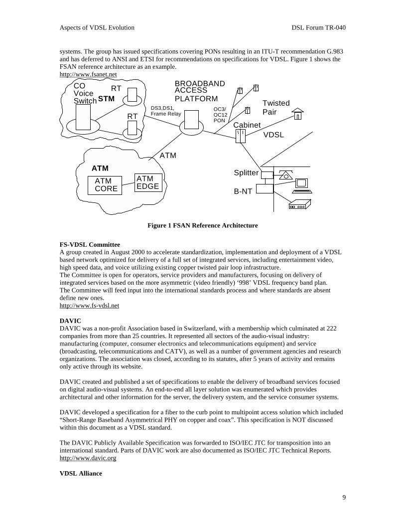
systems. The group has issued specifications covering PONs resulting in an ITU-T recommendation G.983and has deferred to ANSI and ETSI for recommendations on specifications for VDSL. Figure 1 shows theFSAN reference architecture as an example.http://www.fsanet.net
ATMCORE
ATMEDGE
COVoiceSwitch
RT
RT
BROADBAND
PLATFORM
Cabinet
OC3/OC12PON
TwistedPair
STM
ATM
DS3,DS1,Frame Relay
ATM
B-NT
Splitter
VDSL
ACCESS
Figure 1 FSAN Reference Architecture
FS-VDSL CommitteeA group created in August 2000 to accelerate standardization, implementation and deployment of a VDSLbased network optimized for delivery of a full set of integrated services, including entertainment video,high speed data, and voice utilizing existing copper twisted pair loop infrastructure.The Committee is open for operators, service providers and manufacturers, focusing on delivery ofintegrated services based on the more asymmetric (video friendly) ‘998’ VDSL frequency band plan.The Committee will feed input into the international standards process and where standards are absentdefine new ones.http://www.fs-vdsl.net
DAVICDAVIC was a non-profit Association based in Switzerland, with a membership which culminated at 222companies from more than 25 countries. It represented all sectors of the audio-visual industry:manufacturing (computer, consumer electronics and telecommunications equipment) and service(broadcasting, telecommunications and CATV), as well as a number of government agencies and researchorganizations. The association was closed, according to its statutes, after 5 years of activity and remainsonly active through its website.
DAVIC created and published a set of specifications to enable the delivery of broadband services focusedon digital audio-visual systems. An end-to-end all layer solution was enumerated which providesarchitectural and other information for the server, the delivery system, and the service consumer systems.
DAVIC developed a specification for a fiber to the curb point to multipoint access solution which included“Short-Range Baseband Asymmetrical PHY on copper and coax”. This specification is NOT discussedwithin this document as a VDSL standard.
The DAVIC Publicly Available Specification was forwarded to ISO/IEC JTC for transposition into aninternational standard. Parts of DAVIC work are also documented as ISO/IEC JTC Technical Reports.http://www.davic.org
VDSL Alliance

Aspects of VDSL Evolution DSL Forum TR-040
10
An interest group created to promote Multi-Carrier Modulation (DMT and FMT) as the preferred line codefor VDSL standardization. The group develops text proposals for Multi-Carrier Modulation VDSL andfeeds it into the various standards processes.The organization is open for all with an interest in Multi-Carrier Modulation for VDSL.http://www.vdslalliance.com
VDSL CoalitionAn interest group created to promote Single Carrier Modulation (CAP / QAM) as the preferred line codefor VDSL standardization. The group develops text proposals for Single Carrier Modulation VDSL andfeeds it into the various standards processes.The organization is open for all with an interest in Single Carrier Modulation for VDSL.http://www.vdsl.org
6 VDSL Service Characteristics
6.1 VDSL RequirementsThe basic service requirements for VDSL are set out in the relevant ETSI, T1and FSAN publications. For amore complete description, the reader should refer to these documents (see references [1], [4] and [6]).
6.2 VDSL CharacteristicsThis section contains a summary of the service characteristics provided by the proposed VDSL standards.Differences by standards organization are outlined where applicable.
6.2.1 Rate versus ReachETSI has defined two classes of operation for VDSL, Class I covering asymmetrical use and Class IIcovering symmetrical use; the performance objectives for these various service types are as follows:
Service Type Downstream Rate(Mbps)
Upstream Rate(Mbps)
Best/worst caseReach
(m)
[PSD mask 1]
Best/worst caseReach
(m)
[PSD mask 2]
Asymmetric (A4) 23.268 4.096 896/453 995/534
Asymmetric (A3) 14.464 3.072 1,294/729 1,344/820
Asymmetric (A2) 8.576 2.048 1,592/789 1,691/882
Asymmetric (A1) 6.4 2.048 1,689/843 1,791/936
Symmetric (S5) 28.288 28.288 N/A 298/212
Symmetric (S4) 23.168 23.168 N/A 397/261
Symmetric (S3) 14.464 14.464 796/580 845/575
Symmetric (S2) 8.576 8.576 1,245/820 1,294/820
Symmetric (S1) 6.4 6.4 1,392/881 1,444/876
Table 1 ETSI Rate vs. Reach
Committee T1 has proposed a set of data rates for VDSL based on short, medium and long lines as well aspredicted loop lengths – see Table 2:
Service Type Downstream Rate
(Mbps)
Upstream Rate
(Mbps)
Reach
(m)

Aspects of VDSL Evolution DSL Forum TR-040
11
Asymmetric Short 52 6.4 300
Asymmetric Short 38.2 4.3 300
Asymmetric Short 34 4.3 300
Asymmetric Medium 26 3.2 1000
Asymmetric Medium 19 2.3 1000
Asymmetric Long 13 1.6 1500
Asymmetric Long 6.5 1.6 2000
Asymmetric Long 6.5 0.8 2000
Symmetric Short 34 34 300
Symmetric Short 26 26 300
Symmetric Short 19 19 300
Symmetric Medium 13 13 1000
Symmetric Long 6.5 6.5 1500
Symmetric Long 4.3 4.3 1500
Symmetric Long 2.3 2.3 1500
Table 2 Committee T1 Rate vs. Reach
The rate and reach values in Tables 1 and 2 assume .4mm (or equivalent) wire gauge. See the relevantstandard for the conditions under which these performance objectives are achieved, including PSD mask,BER, noise model, test loop, etc..
6.2.2 Bit Error RatioThese rate/reach requirements are defined so that a 6 dB noise margin degradation would yield a bit errorratio under the test conditions of less than 1 in 107. This procedure is defined so that testing can beaccomplished within reasonable time periods. In normal operation the modems are expected to operatenominally error-free under these conditions. In practice error performance requirements may depend on thetype of service and would be determined by the network operator.
6.2.3 LatencyThe standards define both single and dual latency modes.
In single latency mode, all the system data payload capacity is dedicated to one channel. This modeprovides programmable burst error protection. The latency of this path is a function of the data rate and theamount of burst error protection. The latency is programmable by the network management system.
In dual latency mode two channels are provided, a “low latency” fast channel and “higher latency” slowchannel. The slow channel provides programmable burst error protection as described above. Theallocation of capacity between the two channels is performed according to parameters provided by thenetwork management element manager.
6.2.4 Spectral CompatibilityEnsuring spectral compatibility with existing and future DSL transmission systems is of paramountimportance to Network Operators. The following VDSL spectral characteristics are separated into thosewhich apply to adjacent wire-pairs, and the same wire-pair, which may be used as transmission bearers forother forms of service (e.g. POTS, ISDN, etc.). As an example, working group T1E1.4 has approved a draftstandard to address the spectral compatibility between CO based DSLs and network legacy systems.

Aspects of VDSL Evolution DSL Forum TR-040
12
Designated T1.417, this standard does not address the issue of compatibility between DSL transmissionsstarting from different points in the network, e.g., CO and cabinet. Guidelines covering this and networkrepeaters are expected to be included in the second version.
6.2.4.1 Adjacent Wire-pairsVDSL systems have been designed to operate with a number of different DSL systems operating onadjacent wire-pairs in a multi-pair cable. Each of the other systems will generate crosstalk which willappear as unwanted noise at the front-end of a VDSL receiver. Both Asymmetric and Symmetric VDSLsystems may be operated on different wire-pairs within a multi-pair cable provided that they use the samefrequency band plan. No special arrangements are required for pair selection.
All VDSL standards provide for co-existence with an installed base of xDSL systems (e.g. HDSL, ADSL,ISDN, etc.) and other systems operating in the same multi-pair cable.
6.2.4.2 Same Wire-pairVDSL has also been designed to co-exist with some narrowband services that may be carried on the samewire-pair. This is to ensure that the VDSL system can provide a broadband overlay capability. In particular,VDSL is able to operate at frequencies above POTS and both 2B1Q and 4B3T forms of ISDN-BasicAccess.
A splitter filter is used to achieve frequency separation of the VDSL signals from the POTS or ISDNsignals.
7 Service Evolution to VDSL
7.1 Service MigrationThe migration of services from ADSL to VDSL based services is driven by the value added higher rateservices enabled by VDSL. The factors determining the pace of service evolution however are different forGreen Field versus existing plant deployments.
7.2 Service Evolution on Green Field SitesIn the Green Field case, new customers receive a broadband connection upon initial service installation.The hub is fed by optical fiber and the Network Access Provider has a choice of ADSL or, when available,VDSL based service delivery. New Housing and Business Park developments today are typically built outof City Centers and close to main Autoroutes. Many of these Green Field developments are often beyondthe reach of an ADSL based Central Office DSLAM. Consequently many such sites are connected by fiberoptic (NGDLC or PON) back to a Central Office in the City Center.
Examples of Green Field Deployments include:• New Residential Developments• New Business Park Developments• First access to Multi Tenant Units• New extensions to existing Campus Networks• Newer fiber fed NGDLC deployments
In this Green Field case the complexity of infrastructure required for VDSL and ADSL Service is similar.For deployment scenarios see section 8. In a simple choice of ADSL versus VDSL, VDSL is veryattractive, offering faster service rates and providing a seamless evolution path to VDSL enabled Premiumservices. VDSL provides the Network Access Provider additional revenue streams for no additionalinvestment and future proofs the customer.In this way Green Field deployment of VDSL can provide early access to advanced services. For thisstrategy to work however the VTU-R must provide access to current broadband services as well as access

Aspects of VDSL Evolution DSL Forum TR-040
13
to VDSL enabled services when available. It must also support a range of legacy CPE equipment byappropriate choice of user interface.Where VDSL is not available ADSL and SDSL based service modules can be changed later withcompatible VDSL modules to provide access to VDSL enabled services. This requires a Common AccessArchitecture supporting SDSL, ADSL and VDSL.
European PTTs face strong competition from Cable operators on residential sites. By bundling televisionservices with telephony, cable operators take a significant percentage of new lines. In countries where PTTsare allowed a Broadcast License, VDSL provides a route for incumbents to exploit the opportunity forvideo and data services on Green Field sites, providing a competitive service offering and at the same timedeveloping the infrastructure for future deployment of Fiber to the Home.
7.2.1 Factors enabling VDSL Service on Green Field Sites• Compatibility with the DSL Forum Network Architecture allows support for ADSL based Services
over VDSL and by appropriate choice of user interface, compatibility with ADSL based CPE.• The length of copper loops, from DSLAM to customer on Green Field sites is typically less than 500
meters. VDSL can provide greater capacity than ADSL on such short lines.• The additional capacity of VDSL provides a route to upgrade to faster VDSL enabled services later
without additional infrastructure and without the need for a site visit.• VDSL offers ease of upgrade as services evolve, reducing churn for VDSL based customers.• The lack of existing Broadband services on Green Field sites minimizes the risk of cross talk.• Green Field deployment offers ILECs with a Broadcast License the opportunity to compete more
effectively with Cable Operators.
7.2.2 Challenges to VDSL Service on Green Field Sites• Availability of Standardized Product solutions for VDSL based Services• Interoperability of VDSL based CPE• Electromagnetic compatibility with Amateur band radio broadcast.
7.3 Service evolution on Existing PlantIn the case of existing plant, broadband services are already available from other service platforms. In thiscase, upgrade to a VDSL based service requires additional infrastructure that must be justified solely by thedemand for VDSL enabled services. Examples of existing plant deployment include:• Public Broadband Access Networks• Campus Environment• Multi-tenant Environment
In existing plant deployments the time to deploy a VDSL based Service platform restricts the rate of VDSLdeployment. The need to obtain planning permission for Street cabinets and the civil works required to runfiber to the curb or building restrict market growth and constitute a barrier to deployment.
In this existing plant case, VDSL must be spectrally compatible with other broadband services. Thisincludes ADSL and SHDSL based services from Central Office based DSLAMs.
VDSL has the ability to overlay a number of existing services (POTS, ISDN, ADSL). If different NetworkAccess Providers provide these services, several broadband service platforms share the local loop in a Linesharing arrangement. This creates demarcation issues in Fault Management and Service Management.
Line Sharing can be avoided if a single VTU-R displaces existing broadband NTs. This requires that theVDSL based service platform support ADSL based services in the near term, alongside VDSL enabledPremium services. An appropriate choice of user interface is also required to provide compatibility with arange of legacy CPE equipment. A Common Access Architecture supporting both ADSL and VDSL is alsorequired.

Aspects of VDSL Evolution DSL Forum TR-040
14
7.3.1 Factors enabling VDSL Service on Existing Plant• Compatibility with the DSL Forum Network Architecture allows support for ADSL based Services.• VDSL is spectrally compatible with a range of Central Office based Service platforms and allows Line
Sharing with services including POTS, voiceband services (V.90) and ISDN BRI.• VDSL can potentially displace existing service platforms with a single VTU-R supporting existing
services and CPE equipment alongside VDSL enabled services.
7.3.2 Challenges to VDSL Service on Existing Plant• Availability of Standardized Product solutions for VDSL based Services• Interoperability of VDSL based CPE• Electromagnetic compatibility with Amateur band radio broadcast.• Complexity of service management and fault management associated with Line Sharing.• The time and resources required in deploying VDSL services from street cabinet sites.• Whether the plant construction enables VDSL to meet minimum service coverage requirements
7.4 Two stage Evolution of VDSL ServicesThe compelling case for VDSL Service on Green Field sites will ensure early evolution to a VDSL enabledService Platform.
The deployment of ADSL based service Platforms will capture the majority of customers in closeproximity to the City Center based Central Office. Deployment will then migrate to smaller offices andRemote Concentrator sites served by an optical fiber link back to the central office. As deploymentcontinues the Service Node will get smaller and closer to the customer. Where small sites have short loops,new opportunities for Green Field Deployment will be created. Existing plant deployment will follow asServices demand exceeds the available capacity of ADSL lines. This is likely to happen first on longerloops, which support only the lower ADSL service rates. The success of early deployment of services toGreen Field sites will be a key driver in creating demand for VDSL enabled services in existing plantdeployment.
7.5 VDSL Enabled ServicesThe tables below identify typical sets of VDSL enabled services for Residential and SME customers.Approximate Service rates are identified along with the need for a Guaranteed Service Rate and ServiceProtection. The service rates indicated are approximate and provided to assist in mapping a given set ofservices to actual bearer rates defined in section 6. The Service Set for Residential customers has a highvideo content and is suited to Asymmetric bearer rates. The video service rates in the residential caseassume 3 simultaneous MPEG2 video channels (including audio) of at least 5 Mbps per channel. TheService Set for SME customers requires roughly equal upstream and downstream rates and is thereforesuited to symmetric bearer rates.
Service Type(Asymmetric-Residential)
Downstream Rate(Mbps)
Upstream Rate(Mbps)
ServiceGuarantee
ServiceProtection
Video Services (3 Channels)-Switched Video Broadcast >15 <0.2 Yes No-Stagger Cast >15 <0.2 Yes No-Video on Demand >15 <0.2 Yes NoAudio Services-Hifi Audio on Demand >1 <0.1 Yes No-Online radio >1 <0.1 Yes NoInternet/Intranet-Download Multimedia >10 <0.1 Best Effort No-Download Applications >10 <0.1 Best Effort No-Virtual Reality Gaming >10 <1 Best Effort No-Online shopping >10 <0.1 Best Effort No

Aspects of VDSL Evolution DSL Forum TR-040
15
(Download of Soft goods)-Website Hosting >0.4 >2 Best Effort NoDerived Voice-VoDSL (ATM)(< 4 channel)
<0.32 <0.32 Yes No
-VoIP(< 4 channel)
<0.32 <0.32 Best Effort No
Table 3 Residential Service Set
Service Type(Symmetric SME)
Downstream Rate(Mbps)
Upstream Rate(Mbps)
ServiceGuarantee
ServiceProtection
Office Communications-Derived Voice(>16 channel PCM @ 64Kbps)
<2 <2 Yes Yes
-High Quality Video Conferencing <8 <8 Yes YesInternet/Intranet-Large File transfer >10 >10 Best Effort Yes-Application download >10 <2 Best Effort Yes-Access Virtual Reality Websites >10 <2 Best Effort Yes-Media hosting (Webcast) <2 >10 Best Effort Yes-Website Hosting <2 >10 Best Effort Yes-Remote Learning Applications >10 <2 Best Effort Yes
Table 4 SME Service Set
Some operators will offer different combinations of these services.
8 Deployment Scenarios
8.1 Example Deployments
8.1.1 Public Broadband Access NetworksThe ultimate goal for access network operators is to deliver high bandwidth services to their customersexploiting fiber all the way to the premises. Today's fiber to the home (FTTH) networks are noteconomical, because of the high infrastructure costs to deploy optical fibers within the last mile to thecustomer.
Hybrid fiber-copper systems deploying VDSL in the last mile to the customer offers sufficient bandwidthand is more economical than pure fiber networks, therefore Fiber to the Curb/Cabinet (FTTC/FTTCab)solutions are regarded as an intermediate step towards the ultimate goal.
In residential applications where the bandwidth needs are asymmetric, approx 15 Mbps downstream and 1Mbps upstream, VDSL will reach about 1 km. For the SME, bandwidth needs are typically symmetric,approx 10 Mbps, and VDSL will reach about 0.7 km. The rates and reach depend upon the existing copperinfrastructure and other deployed services.
Like ADSL, VDSL systems also offer the possibility to transport POTS or ISDN baseband signals over thesame line. VDSL splitters may be electrically different than their ADSL equivalent due to the higherfrequencies used for VDSL systems.
Due to a different access network structure, fiber to the cabinet, there is a significant cost associated withthe deployment transition from ADSL to VDSL. When an optical fiber is used to transport broadbandsignals to a curb/cabinet, new broadband services (e.g. Switched Digital Video, faster / symmetrical
Aspects of VDSL Evolution DSL Forum TR-040
16
Internet access) utilizing VDSL technology can be offered to customers. Utilizing existing CO equipment(DSLAMs) in a curb/cabinet may not be possible due to different environmental conditions. While it maybe desirable to re-use existing CPE equipment this may not be possible due to higher data rates anddifferent service delivery architectures.
8.1.2 Campus EnvironmentVDSL has particular relevance to the Campus environment when used in its Symmetrical form.
With the concept of a fiber fed ONU placed reasonably centrally within the campus, symmetrical VDSL atspeeds up to 10 Mbps may be used to connect all the campus locations within a radius of some 700 metresfrom the hub. For either an existing or new campus, twisted pair copper wire may be used for the final dropfrom the ONU to the user terminal. Provided the radial distances fall within those accessible using VDSL,this will provide a comparatively cheap and easy to install and provision method of providing high-speedaccess throughout a typical campus development.
There are a number of advantages from using VDSL for such campus installations:
• Ease of installation;• Cost of installation;• Speed/bandwidth available;• Dependence on a standard.
8.1.2.1 Ease of InstallationExisting copper pairs may be used where these are available or new copper may be easily installed atcomparatively low cost. In practice, most campus environments will be built with twisted copper wiringinstalled and available and this may be then used for VDSL.
8.1.2.2 Cost of InstallationWith wiring already available, no major engineering work will be required to provision the physicalnetwork on the campus site. New terminal equipment will be required but this will be needed in some formwhatever high speed access solution is chosen.
It is envisioned that a VDSL hub will be centrally located in the campus. This may either be fiber fed fromsome remote location to provide wide area connectivity or possibly could be stand-alone simply to servethe campus. In the latter case, all connection to locations within the campus site could be provided usingtwisted copper pairs and no fiber feed would be needed.
8.1.2.3 Speed/Bandwidth AvailableUsing VDSL, a 10 Mbps symmetrical service could be provided throughout the campus. Traditionally, thiswould have required fiber to every user, probably on some form of SONET/SDH ring. With VDSL, such asophisticated delivery mechanism would not be required and additional bandwidth could be provided bythe simple use of additional copper pairs, assuming that these were available.
8.1.2.4 Dependence on a StandardSince it is envisioned that any campus site would be under the control of a single organization, be that a sitemanagement company or a singe company/organization, standards would not be needed. The site managerscould purchase all the necessary VDSL equipment from a single supplier. Even with an off-campus fiberfeed, there would be no need for a specific VDSL standard.
Even without a formal standard for VDSL, never the less, any implementation will need to adhere to certainrules:
• It must be spectrally compatible with other services in any binder group;

Aspects of VDSL Evolution DSL Forum TR-040
17
• All VDSL services in a cable or binder group must use the same up and downstream frequencies;• All VDSL services must fit within the same frequency band plan, 997, 998 or Fx.
8.1.2.5 Typical Deployment ScenariosTypical scenarios include:
• Hospital sites;• Company campuses;• Business Parks;• “Vertical” campuses;• Universities/Colleges;• Factories.
8.1.2.5.1 Hospital SiteFor a hospital campus with many separate buildings, VDSL provides an excellent means to build andextend PACS type radiological image distribution. Here, the radiological images are of a very dense naturerequiring very high bandwidth for rapid transmission – VDSL is ideal.
8.1.2.5.2 Company CampusesWith a typical company site, with many separated buildings, VDSL offers a cheap and fast to install highbandwidth communication solution. All buildings may be connected using existing copper pairs providingthe necessary path for VDSL speed data transmission.
8.1.2.5.3 Business ParksThe typical business park is envisioned as a campus with many separate commercial tenants. The Parkmanagement company may use VDSL – in this case probably with an off-site fiber feed, to provide eachseparate business unit with broadband communications.
8.1.2.5.4 Vertical CampusesA vertical campus is seen as a large MTU with separate tenants on each floor or even several tenants onone floor. In all other respects, it is seen as equivalent to a special case of a business park.
8.1.2.5.5 Universities/CollegesUniversities and colleges are similar in some ways to hospitals. There is a single overall controllingorganization with many separate buildings with a growing need for high bandwidth communications.
8.1.2.5.6 FactoriesNot often talked about in the context of VDSL, large factory sites are another possible location for the useof VDSL, particularly those needing to communicate dense information such as detailed designs andengineering specifications around the site. Typically, even the largest factories will be less than 2,000metres from end to end so allowing the use of VDSL over the existing twisted copper pair communicationinfrastructure.
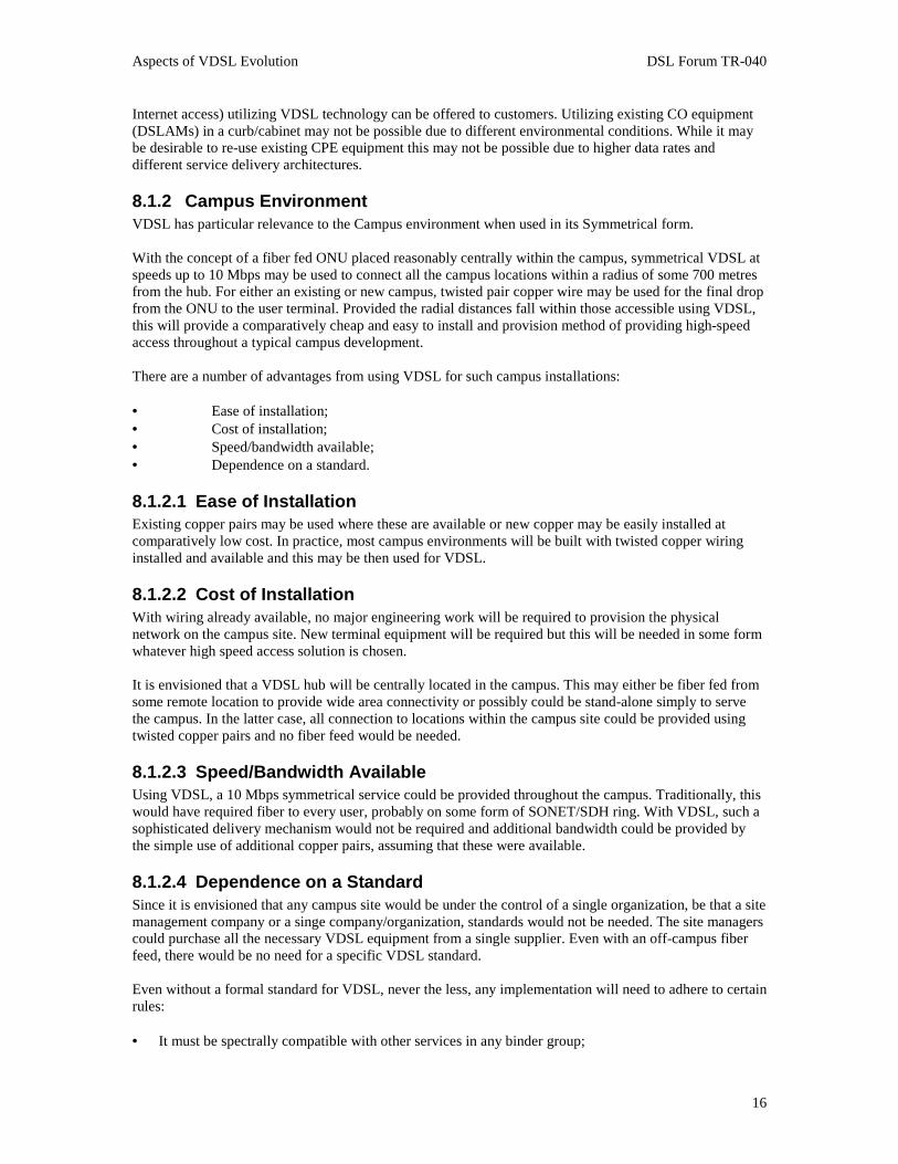
8.1.3 Multi-tenant EnvironmentThe VDSL multi-tenant environment consists of service delivery to both business and residentialsubscribers. Business subscribers are typically small-to-medium enterprises leasing office space in Multi-tenant Units (MTU) such as office parks and strip malls. Residential subscribers are typically consumersrenting living space in Multi-dwelling Units (MDU) such as apartments and town homes. Figure 2illustrates typical Fiber-to-the-Building (FTTB) and Fiber-to-the-Cabinet (FTTCab) MDU/MTUarchitectures that are ideal for VDSL deployments. For FTTB the VTU-O is located in the basement orwiring closet. For FTTCab the VTU-O is co-located with the existing POTS junction wiring interface orDLC, or can be integrated in a new NGDLC.
Aspects of VDSL Evolution DSL Forum TR-040
18
Figure 2 VDSL MDU/MTU FITL Architecture
8.1.3.1 MTU EnvironmentThe MTU environment to serve SMEs requires symmetric rates from 1.5 Mbps to greater than 10 Mbps.Example services to be carried by VDSL to this environment include multi-megabit Internet access, LANextensions and dedicated data services; telephony services including multi-port derived telephony (VoDSL,VoIP) and T1/E1 replacement; and video services including digital broadcast, video-on demand,surveillance and video teleconferencing. The ability of the service provider to support guaranteedbandwidth via Service Level Agreements is likely to be important.
8.1.3.2 MDU EnvironmentThe MDU environment to serve consumers requires asymmetric rates in excess of 15 Mbps downstreamand 1 Mbps upstream to support up to three simultaneous digital video streams plus multi-megabit Internetaccess, lifeline telephony and two or three lines of derived telephony (VoDSL, VoIP). This is required toeffectively compete with emerging digital CATV technologies and service offerings. Quality of service forvideo entertainment and telephony services is critical, while best effort is sufficient for Internet service.
8.1.3.3 Ease of InstallationMost, if not all, MTU/MDU environments have existing copper pairs to each unit from a commondistribution point. These pairs can be easily utilized to deliver VDSL-based services, which means no newwiring. VDSL splitters would need to be used to maintain lifeline POTS services where required.
8.1.3.4 Cost of InstallationWith wiring already available, no major engineering work will be required to provision the physicalnetwork in the MTU/MDU site. New terminal equipment will be required but this will be needed in someform whatever high speed access solution is chosen.
It is envisioned that a VDSL access switch or concentrator will be located in the basement or wiring closetof the MTU/MDU. This will likely be fiber fed from some remote location (e.g. CO or other VDSL node)to provide high bandwidth for backhaul to the core network.

Aspects of VDSL Evolution DSL Forum TR-040
19
8.1.3.5 Speed/Bandwidth AvailableUsing VDSL, as much as 52 Mbps could be provided throughout MTU/MDU buildings. Available linerates will depend upon copper loop lengths and the adoption of VDSL standards. Typically, residentialservices to MDUs would be 22/3 Mbps downstream/upstream and business services to MTUs would be 13Mbps symmetrical.
8.1.3.6 Dependence on a StandardCommunication services to MTUs and MDUs are typically under the control of the building owner or RealEstate Investment Trust, and the building management company. Because the copper infrastructure insidethe building is not part of the public network, there is central control by the owner or manager over theservices distributed over this infrastructure. This central control reduces the need for VDSL standardscompliance since the site managers could purchase all the necessary VDSL equipment from a singlesupplier. Therefore, early VDSL deployments could begin in these markets segments. Note that complianceto other existing standards, such as SONET/SDH and SNMP, is highly desirable for any installations asbackhaul to the core network will be required.
Even without a formal standard for VDSL, any implementation will need to adhere to certain rules:
• It must be spectrally compatible with other services in any binder group;• All VDSL services in a cable or binder group must use the same up and downstream frequencies;• All VDSL services in a cable or binder group must fit within the same frequency band plan, 997, 998
or Fx.
8.1.3.7 Typical Deployment ScenariosTypical scenarios include:
• High rise apartments• Condominiums and townhomes• High rise commercial buildings• Strip malls• SME office parks• Hospitals• Dormitories• Hotels and motels
8.1.4 Home NetworkingThe use of VDSL as a home networking vehicle is beyond the scope of this document and from recentadvancements in Home Networking technologies it appears that VDSL will not be an approach selected.However, VDSL will terminate in the home on a device that provides the connection to the services offeredwithin the home. This device is often called the Residential Gateway (RG).
Since the RG is the connection between the Access Network and the In-Home local area network (beingcalled a RAN – Residential Area Network by some), it will become a critical piece of the network. It willhave a direct impact on the success of VDSL as one of the possible access technologies available.
8.2 Network TopologiesVDSL as defined by ETSI, T1& ITU-T is a point to point transmission technique across the U referencepoint as defined in TR-001 and TR-012. However VDSL may be used to realize different end-to-endnetwork topologies as described below. The operator of the VDSL network will determine depending onthe applications running on top of his networks which VDSL service profile (asymmetric / symmetric, datarates, transport protocols) will be chosen.It should be noted that VDSL as defined above is always directional with a well defined head end (VTU-C)and remote end (VTU-R) functionality, even if the service profile is symmetric. The concept of VDSL

Aspects of VDSL Evolution DSL Forum TR-040
20
using FDD to avoid near end crosstalk (NEXT) requires that VTU-Cs are not collocated with VTU-Rs atone end of a shared cable in order to guarantee proper operation.
8.2.1 Star NetworksThe most common topology for DSLs is a star network. The purpose of the network is to interconnectmultiple endpoints located at various customer premises with one centrally located endpoint.
Typically multiple VDSL endpoints at the central location are realized as multiple VDSL port devices (linecards) using the same housing (DSLAM, ONU,....) whereas VDSL endpoints at the customer premises areusually single VDSL port devices (Set Top box, Residential Gateway, PC card, ...). Within these topologiesthe head end functionality (VTU-C) of each VDSL link is always located in the central location. The clearstructure of a star network requires minimal network engineering, even if an operator of the star networkchooses different service profiles for each VDSL connection.
8.2.2 Point-to-PointBecause of the point to point nature of VDSL, Point to point networks utilizing the benefits of VDSL are ofparticular interest. Some common applications for VDSL point to point networks include the provision ofan individual high speed connection or to multiplex a number of lower speed connections onto a single highspeed VDSL connection. In this scenario a symmetric service profile would likely be chosen. Due to theindividual requirements in terms of required bandwidth, distance and transport each VDSL connection mayhave a specific profile. Operating a higher number of point to point VDSL connections within a cable plantmay require a certain level of network engineering.
8.2.3 Mesh NetworksUsing VDSL to realize meshed networks, a combination of many point-to-point VDSL connections and/orstar networks, seems to be very attractive due to the high number of possible service profiles (symmetric /asymmetric, big variety of datarates). However realizing meshed networks with VDSL requires a high levelof network engineering to respect the requirements of VDSL at the physical layer.
9 Regulatory barriers and related issues
9.1 UnbundlingVDSL from the exchange is governed by the same unbundling rules as other DSLs. Both loop and spectralunbundling is required. Subloop unbundling, access to the final drop, is also required.
The selection of allowable frequency band plan for any particular element of copper plant may be in thedomain of the incumbent operator, or may be a subject for national regulation.A firm regulatory basis is essential for mass deployment of VDSL by network operators, for a number ofreasons.
There can only be one frequency band plan but this may be contentious since it has a major impact on thekind of service that may be provided. Also, the specific connection rules have an important bearing on thelocation and method of connection to the installed plant impacting both incumbent and competitiveoperators.
Since VDSL may use frequencies below 1 MHz, the spectrum management regulations applicable to otherDSLs and ADSL in particular will need to consider VDSL.
9.2 EMCCurrent EMC regulations have not proven to be a serious impediment to DSL deployments in general.These requirements were considered in defining the Power Spectral Density limits for VDSL. Furtherlimitations were adopted to reduce potential interference to radio amateur installations in the vicinity ofVDSL deployments.

Aspects of VDSL Evolution DSL Forum TR-040
21
However, spectrum regulators in Germany and the UK have recently become concerned that the existingEMC limits are not sufficient to prevent significant interference being experienced by licensed spectrumusers. This is despite the development of recent standards that allow much higher levels of emissions fromhigh efficiency lighting systems.
These regulators plan to put in place regulatory instruments providing limits applicable to resolution ofinterference complaints. They have a general power to shut down any source of interference. This power isnot constrained by any lower limit to the enforcement threshold.
However, RegTP in Germany, and the Radio Communications Agency in the UK, are developingregulations for resolution of interference complaints that provide a measurement method and interventionthreshold to be applied to systems in service. These provide guidance to equipment and system developers,and prevent further dispute in most cases. Nevertheless, in particularly sensitive cases systems may be shutdown even if their emissions are below these levels.
The current RegTP specification (Usage Provision NB30) covers frequencies from 9 kHz to 3 GHz. TheRA specification (MPT1570) covers 9 kHz to 300 MHz. The RegTP specification has been approvedcovering only the bands up to 1.6 MHz. However, work has started to extend the provisions to include thewhole range of frequencies used by VDSL.
There is currently controversy regarding these regulations arising from the contradictory interests of RFspectrum users and the telecommunications industry. At present the most vocal spectrum users are the AMbroadcasters and civil aviation authorities, but considering VDSL, the defense community will set stringentobjectives.
The levels proposed by the UK radio communications agency in particular (April 2000), is so low as tomake deployment of ADSL highly risky for network operators. Indications are that when VDSL isconsidered the network operator risk may be the same or worse.
9.3 RF Ingress and Egress from Unshielded WireUnshielded wire pairs tend to act as radio frequency antennas, allowing both ingress of broadcast and otherradio signals that represent noise to a DSL system, and egress of broadband noise that can interfere withreception in radio receivers. Other ingress noise sources include electrical equipment and machinery.
Emissions from DSL systems at frequencies below 1 MHz have been shown to be close to, but potentiallyhigher, than levels deemed acceptable by radio spectrum regulatory authorities. However, the 'antenna'efficiency of premises wiring, and in particular overhead drop wires, increases markedly at frequencies inthe range 1 MHz to 20 MHz that may be occupied by VDSL. Work in ETSI and ANSI has previouslydemonstrated that significantly lower power spectral density must be used at VDSL frequencies to makethe emissions acceptable to the regulatory agencies.There are two modes of emission that are significant for unshielded wire pairs: direct magnetic couplingfrom differential mode signals on untwisted or poorly twisted wires, and electromagnetic coupling fromcommon mode signals on all kinds of exposed wiring.
A critical issue controlling emissions from common mode signals is system balance. The balance of thecable itself is important, but other factors may dominate. These include: the balance of the multi-pairdistribution plant to which the cable is attached, terminal equipment balance, and point disturbances such ascable securing methods in overhead plant.
It is often assumed that shielding or burying the cable is sufficient to overcome ingress and egressproblems. However, poor grounding of cable shields can negate the effects of shielding, and it has beenreported by some workers that common mode signals found on underground wiring can in somecircumstances be as high as on overhead drops.
Aspects of VDSL Evolution DSL Forum TR-040
22
Emissions can impact domestic short wave radio receivers as well amateur radio receivers that are close toVDSL installations. However a potentially more serious problem exists in the ensemble effects ofpotentially millions of lines. The spectrum between 1 MHz and 20 MHz is allocated to a large number ofspectrum uses. Some of these are high priority, including military, security, diplomatic, aviation andseafaring, life critical services.
As well as degrading performance, ingress from licensed radio spectrum usage can cause legal and personaldisputes. In particular, amateur radio transmitters may cause complete disruption to service if modems haveinadequate immunity to common-mode interference-signals. Neighbor - neighbor disputes are oftendifficult to resolve for network operators and EMC enforcement agencies.
9.4 Unregulated interference issuesVDSL may suffer interference from other systems using spectrum shared with VDSL. This interferencemay arise directly from signals that are intended to be confined to in-premises telephony wiring, orindirectly from signals on other media that couple into telephony wiring.
The class of direct interference sources includes the HomePNA and related ITU G.pnt transmissionsystems. It has been demonstrated that these systems do in fact interact - even if they are used by differentcustomers served by loops in the same cable. In an ideal world, whenever G.pnt is deployed, there shouldbe a filter to isolate VDSL on the loop plant from in-premises wiring carrying G.pnt signals. However sinceG.pnt is user-installed, this is hard to ensure, even if unbundling regulations theoretically control equipmentthat can be connected to the loop plant.
Indirect interference can arise from signals carried on other media such as electrical power supply cablesboth outside and inside the home. These are relatively large signals on wiring that may be installed close totelephony cables carrying VDSL, that may cause interference by electromagnetic coupling. From aconsideration of likely worst-case coupling, the existing EMC regulations may not be sufficient to preventsignificant performance impairment to VDSL. However in some countries the new EMI emissionsregulations discussed above may have the side effect of limiting deployment of the sources in question.

Aspects of VDSL Evolution DSL Forum TR-040
23
Editors Note: this page will not form part of the final technical report.
Contributory Material to this Technical Report
The following DSL Forum contributions have been made on this technical report and their commentsincorporated:
1. 99-344, Minutes of Emerging DSLs Study Group Meeting – Nov 17th & 19th. David J K Greggains,Gorham & Partners Ltd, Paris meeting, February 2000.
2. 00-029, Service evolution and Deployment scenarios for Working Text 99-047 "Aspects for VDSLEvolution". Wolfgang Kluge, Marconi Communications GmbH, Paris meeting, February 2000.
3. 00-225, WT-047 Section 5.3.1 Draft. David J K Greggains, Gorham & Partners Ltd, Dublin Meeting,August 2000
4. 00-245, WT-047 Appendix A-1. Chuck Van Dusen, VideoTele.com, Dublin Meeting, August 20005. 00-254, VDSL Standardization status update. Piotr Korolkiewicz & Jan Boström, Ericsson, Dublin
Meeting, August 20006. 00-403, Service Evolution to VDSL, Robert Daley, Fujitsu Telecommunications Europe Ltd, Portland
Meeting, December 20007. 01-078, Vote and Comments to Straw Ballot WT-047, Sabit Say-Otun, Next Level Communications,
Vancouver Meeting, March 2001
WT-047 Revision History
Revision Date Issued Editor Comments1 April, 2000 Chuck Storry Initial strawman of WT-047 incorporating comments from
99-344 and 00-0292 May, 2000 Chuck Storry Initial review in Orlando3 May, 2000 Chuck Storry Output of Orlando meeting4 August, 2000 Chuck Storry Working text with contributions merged5 August, 2000 Chuck Storry Output of Dublin meeting6 November, 2000 Chuck Storry Included interm input from mailing list7 December, 2000 Chuck Storry Included text from Portland Contributions8 March, 2001 Chuck Storry Incorporated Straw Ballot comments