
ASME_B1_12_1989.pdf
68
WICE OF LI ADOPTION NUi'1C.E 1 20 January 1989 for ASME/ANSI B1.12-1987 13 July 1987 ASME/ANSI B1.12-1987 was adopted on 20 January 1989 and is approved for use by the Federal agencies. prepared the document for approval by the American National Standards Institute (ANSI). regulations, Point, Naval Publications and Form Center , 5801 Tabor Avenue, Philadelphia, PA 19120-5099, for issue to DoD activities only. All other requestors rflust obtain docunents from: l'he American Society of Mechanical Engineers (ASW Both ASME and ANSI have furnished clearances required by existing Copies of t h i s document are stockeCl by the DoD Single Stock The American Society of Mechanical Engineers United Engineering Center 345 E. 47th Street New York, NY 10017-2330 or The American National Standards Institute 1430 Broadway New York, Ny 10018-3308 Title of hxment: class 5 Interference-Fit Thread Date of Specific Issue Adopted: Releasing Non-Government Standards Body: 13 July 1987 The American Society of Mechanical Engineers Custodians: Navy-As A q - AR Air Force - 99 Review Activities: * Army - AT, AT?, ME, MI Navy - E Air Force - 15 Civil Agency Coordinating Activities: Par - AC0 SA - 7FXE NASA - JFK Military Coordinating Activity: DLA - IS (Project "HE-0069) User Activities : Army - CR, ER DISI'RiBVTION STATEMENT A. Approved for public release; distribution is unlimited. - - -- --------- THIS DOCUMENT CONTAINS I PAGES. , - COPYRIGHT American Society of Mechanical Engineers Licensed by Information Handling Services COPYRIGHT American Society of Mechanical Engineers Licensed by Information Handling Services
-
Upload
meral-acay -
Category
Documents
-
view
21 -
download
2
Transcript of ASME_B1_12_1989.pdf
WICE OF L I ADOPTION NUi'1C.E 1 20 January 1989 for ASME/ANSI B1.12-1987 13 July 1987
ASME/ANSI B1.12-1987 was adopted on 20 January 1989 and is approved for use by the Federal agencies. prepared the document for approval by the American National Standards I n s t i t u t e (ANSI). regulations, Point, Naval Publ icat ions and Form Center , 5801 Tabor Avenue, Philadelphia, PA 19120-5099, fo r i s sue to DoD a c t i v i t i e s only. All other requestors rflust obtain docunents from:
l'he American Society of Mechanical Engineers (ASW
Both ASME and ANSI have furnished clearances required by ex is t ing Copies of t h i s document are stockeCl by the DoD Single Stock
The American Society of Mechanical Engineers United Engineering Center 345 E. 47th S t r e e t New York, NY 10017-2330
or
The American National Standards I n s t i t u t e 1430 Broadway New York, Ny 10018-3308
T i t l e of h x m e n t : class 5 Interference-Fit Thread
Date of Speci f ic I ssue Adopted:
Releasing Non-Government Standards Body:
1 3 July 1987
The American Society of Mechanical Engineers
Custodians:
Navy-As A q - AR
A i r Force - 99
Review Activities: *
Army - AT, AT?, ME, MI Navy - E A i r Force - 15
C i v i l Agency Coordinating Act iv i t ies : Par - AC0 S A - 7FXE NASA - JFK
Mil i tary Coordinating Act ivi ty: DLA - IS (Project "HE-0069)
User A c t i v i t i e s : Army - CR, ER
DISI'RiBVTION STATEMENT A. Approved for public release; d i s t r i b u t i o n is unlimited. - - - - ---------
THIS DOCUMENT CONTAINS I PAGES.
,-
COPYRIGHT American Society of Mechanical EngineersLicensed by Information Handling ServicesCOPYRIGHT American Society of Mechanical EngineersLicensed by Information Handling Services
COPYRIGHT American Society of Mechanical EngineersLicensed by Information Handling ServicesCOPYRIGHT American Society of Mechanical EngineersLicensed by Information Handling Services
E 1 12 A ? 0011333 b
AN AMERICAN NATIONAL STANDARD
Class 5
lnterf erence-Fit
Thread
ASME/ANSI Bl.12-I987 (REVISION OF ANSI B1.12-I 972)
The American Society of Mechanical Engineers
345 East 47th Street, New York, N.Y. 1001 7 -
v _- COPYRIGHT American Society of Mechanical EngineersLicensed by Information Handling ServicesCOPYRIGHT American Society of Mechanical EngineersLicensed by Information Handling Services
ASME B3.32 87 m 2595532 0033334 B m
Date of Issuance: November 15, 1987
This Standard will be revised when the Society approves the issuance of a new edition. There will be no addenda or written interpretations of the requirements of this Standard issued to this edition.
This code or standard was developed under procedures accredited as meeting the criteria for American National Standards. The Consensus Committee that approved the code or standard was balanced to assure that individuals from competent and concerned interests have had an oppor- tunity to participate. The proposed code or standard was made available for public review and comment which provides an opportunity for additional public input from industry, academia, reg- ulatory agencies, and the public-at-large.
ASME does not "approve," "rate," or "endorse" any item, construction, proprietary device, or activity.
ASME does not take any position with respect t o the validity of any patent rights asserted in connection with any items mentioned in this document, and does not undertake to insure anyone utilizing a standard against liability for infringement of any applicable Letters Patent, nor assume any such liability. Users of a code or standard are expressly advised that determination of the validity of any such patent rights, and the risk of infringement of such rights, is entirely their own responsibility.
Participation by federal agency representative(s) or personis) affiliated with industry is not to be interpreted as government or industry endorsement of this code or standard.
ASME accepts responsibility for only those interpretations issued in accordance with-governing ASME procedures and policies which preclude the issuance of interpretations b y individual vol- unteers.
No part of this document may be reproduced in any form, in an electronic retrieval system or otherwise,
without the prior written permission of the publisher.
Copyright 0 1987 by THE AMERICAN SOCIETY OF MECHANICAL ENGINEERS
All Rights Reserved Printed in U.S.A.
COPYRIGHT American Society of Mechanical EngineersLicensed by Information Handling ServicesCOPYRIGHT American Society of Mechanical EngineersLicensed by Information Handling Services

. ASME B1.12 87 m 2575512 0011335 T m
FOREWORD
(This Foreword is not part of ASMElANSl B I . I 2-1 987.)
Interference-fit threads are threads in which the externally threaded member is larger than the internally threaded member when both members are in the free state and which, when assembled, become the same size and develop a holding torque through elastic compression, plastic movement of material, or both. By custom, these threads are designated as Class 5.
Tentative Class 5 fit threads were first published by the National Screw Thread Commission (1928), and alternate Class 5 appeared in the 1944 Handbook H28. These standards were helpful in stabilizing design; however, in spite of restrictive tolerances, loosening or breakage of externally threaded members has been all too frequent. Also, minimum and maximum torque values were established, the validity of which has been generally accepted.
The tentative and alternate standards, which were based on National Bureau of Standards and industry research, testing, and field study, represent the first attempt to establish an Amer- ican standard for interference-fit threads. These specifications are published in Appendix A. In 1947, ASA Sectional Committee B1 on Screw Threads established Subcommittee 10 under the chairmanship of Harry Marchant to study the problems of interference fits. A subgroup of the subcommittee, chaired by W. S. Brown, conducted a comprehensive survey of design, production, and driving practices in the automotive, implement, railroad, and fastener indus- tries and found that all were experiencing difficulty. Typical problems were:
(a) the variety of materials and heat treatments used for externally threaded members; (b) variations resulting from rolling, cutting, or grinding external threads; (c) the huge variety of chemical analyses and physical and mechanical properties encoun-
tered in the forged, cast, die cast, and rolled maeerials into which the externally threaded members are driven;
(d) the widely varying effects of chemical coatings, platings, and lubricants; and (e) the inability to closely control sizes of tapped holes in various materials. It was impossible to establish a standard at that time, but it was agreed that interference-fit
threads could not be eliminated in design of equipment and that a workable standard was essential.
In 1951, Subcommittee 10, later renumbered 12, established a research subgroup which conducted extensive tests under a variety of conditions. The work of this research subgroup and a report of subsequent research and field experience is described in the article ‘‘New Class 5 Interference Fit Thread” by W. G. Waltermire, which appeared in the September 6, 1956 issue of Machine Design.
This Trial American Standard was predicated on the following conclusions, which were drawn from the research and field experience for developing holding torque through plastic movement of materials.
(a) Materials of the external and internal interference-fit threads compress elastically and flow during assembly and when assembled.
(b) - During driving, plastic flow of materials occurs, resulting in either an increase of the external thread major diameter or a decrease in the internal thread minor diameter, or both.
(c) Relieving the external thread major diameter and the internal thread minor diameter to make allowance for plastic flow eliminates the main causes of seizing, galling, and abnormally high and erratic driving torques.
COPYRIGHT American Society of Mechanical EngineersLicensed by Information Handling ServicesCOPYRIGHT American Society of Mechanical EngineersLicensed by Information Handling Services

(d) Relieving the major diameter of external threads and minor diameter of internal threads requires an increase in the pitch diameter interference in order to obtain driving torques within the range established. (In driving studs, it was found that the minimum driving torque should be about 50% greater than the torque required to break loose a properly tightened nut.)
(e ) Lubricating only the internal thread results in more uniform torques than lubricating only the external thread and is almost as beneficial as lubricating both external and internal threads. Some applications do not permit lubrication.
( f ) For threads having truncated profile, torque increases directly as the pitch diameter interference for low interferences, but torque soon becomes practically constant and increases little, if at all, with increases of interference. Obviously, for uniformity of driving torques, it is desirable to work with greater interferences, resulting in plastic flow of materials.
( g ) Comparatively large pitch diameter interferences can be tolerated, provided the external thread major diameter and internal thread minor diameter are adequately relieved and proper lubrication is used during assembly.
(h) Driving torque increases with turns of engagement, but levels off after the assembly is well advanced. (For thin wall applications, it may be desirable to use longer engagement and smaller pitch diameter interference to obtain desired driving torque,)
(i) Studs should be driven to a predetermined depth. Bottoming or shouldering must be avoided. Bottoming, which is engagement of the threads of the stud with the imperfect threads at the bottom of a shallow drilled and tapped hole, causes the stud to stop suddenly during power driving, thus inviting failure in torsional shear. Slipping clutches may permit transmis- sion of excess torque. Bottoming can also damage parts having only a weak diaphragm at the bottom of the hole, through either mechanical or hydrostatic compression. Shouldering, which is the practice of driving the stud until the thread runout engages with the top threads of the hole, may create excessive radial compressive stresses and upward bulging of the material at the top of the hole. The torque, or stud holding power, produced by these radial compressive stresses is considerably relieved when the tensile load is applied to the stud, and may be inadequate to prevent backout in service.
The Trial American Standard was issued in November 1959. On October 23, 1961, the subcommittee reviewed the standard and recommended republication, without technical change, as an American Standard. It was felt that the lack of adverse comment after 2 years existence as a Trial Standard, and the reception of favorable comments of usage, warranted this step. On May 16, 1963, the standard was formally designated an American Standard. Several errors were discovered and B1.12 was rewritten. It was approved on September 5, 1972.
The most recent research on interference-fit thread was conducted by the Portsmouth Naval Shipyard on both hardened steel and nickel-copper-aluminum (K Monel) studs assembled in alloy steel (HY-80), corrosion resistant steel, nickel-copper (Monel), copper-nickel, and nickel-chromium (Inconel) internal threads, and on nonferrous studs in nonferrous internal threads. They modified the B1.12'Class 5 specifications for plastic flow interference-fit threads when nickel-copper-aluminum external threads are assembled in many materials. They also provided more cavity space. A summary of their findings for developing holding torque through plastic flow and elastic compression of material follows.
(a) Pitch diameter interferences specified in ANSI B1.12 were found to be too large, re- sulting in excessive failures.
(b) Lead, flank angles, taper, straightness, and roundness are important. (c) Optimum surface roughness is 63 pin. Ra. (d ) Difference between functional size and pitch diameter of both the internal and external
threads are measured and may not exceed 50% of the pitch diameter tolerances. (One foreign standard specifies 25 % .)
(e) Critical applications require selective fits, using measured pitch diameters on the ex- ternal and internal threads, to obtain a specified interference when the external and internal threads are assembled.
iv
. COPYRIGHT American Society of Mechanical EngineersLicensed by Information Handling ServicesCOPYRIGHT American Society of Mechanical EngineersLicensed by Information Handling Services
ASME 81-12 m 2575532 0013337 m
(f) Assembly torque cannot be continuous. Several waiting periods are required to let fric- tion heat dissipate.
( g ) Studs are indexed to monitor their movement. Assembly is considered a failure if there is stud rotation when seating the prevailing torque nut or breaking it away.
These Portsmouth Naval Shipyard thread specifications are published in Appendix Be for elastic interference where permanent distortion is not desired and Appendix C for plastic flow interference with extra allowance at both the crest and root for K Monel.
This Standard was approved as an American National Standard on July 13, 1987.
COPYRIGHT American Society of Mechanical EngineersLicensed by Information Handling ServicesCOPYRIGHT American Society of Mechanical EngineersLicensed by Information Handling Services

ASME B1-12 87 m 2575512 OOLL338 5 m
ASME STANDARDS COMMITTEE B I Standardization and Unification of Screw Threads.
(The following is the roster of the Committee at the time of approval of this Standard.)
OFFICERS
D. J. Ernanuelli, Chairman H. W. Ellison, Vice Chairman
C. E. Lynch. Secretary
COMMITTEE PERSONNEL
AEROSPACE INDUSTRIES ASSOCIATION OF AMERICA, INC. F. H. Cantrell, McDonnell Douglas Corp., St. Louis, Missouri H. Borrrnan, Alternate, Sperry Defense Electronics, Great Neck, New York
AMERICAN MEASURING TOOL MANUFACTURERS ASSOCIATION P. F. Bitters, Greenfield, Massachusetts C. W. Jatho. Alternate, American Measuring Tool Manufacturers Association, Birmingham, Michigan
AMERICAN PIPE FITTINGS ASSOCIATION W. C. Farrell, Jr., Stockham Valves and Fittings, Inc., Birmingham, Alabama
DEFENSE INDUSTRIAL SUPPLY CENTER E. Schwartz, Defense Industrial Supply Center, Philadelphia, Pennsylvania F. S. Ciccarone, Alternate, Defense Industrial Supply Center, Philadelphia, Pennsylvania
ENGINE MANUFACTURERS ASSOCIATION G. A. Russ, Cummins Engine Co., Columbus, Indiana
INDUSTRIAL FASTENERS INSTITUTE R. M. Harris, Bethlehem Steel Corp., Lebanon, Pennsylvania K. E. McCullough, SPS Technologies, Inc., Newton, Pennsylvania J. C. McMurray. Russell, Burdsall &Ward Corp., Cleveland, Ohio J. A. Trilling, Holo-Krome Co., West Hartford, Connecticut C. J. Wilson. Industrial Fasteners Institute, Cleveland, Ohio
MANUFACTURERS STANDARDIZATION SOCIETY OF THE VALVE AND FITTINGS INDUSTRY W. C. Farrell, Jr., Stockham Valves and Fittings, Inc., Birmingham, Alabama
METAL CUTTING TOOL INSTITUTE (TAP & DIE DIVISION) A. D. Shepherd, Jr., UnionlButterfield Division, Litton Industrial Products, Derby Line, Vermont
NATIONAL ELECTRICAL MANUFACTURERS ASSOCIATION J. B. Levy, General Electric Co., Schenectady, New York F. F. Weingruber, Westinghouse Electric Corp., Pittsburgh, Pennsylvania T. A. Farkas, Alternate, National Electrical Manufacturers Association, Washington, D.C.
NATIONAL FASTENER DISTRIBUTORS ASSOCIATION J. F. Sullivan, Accurate Fasteners, Inc., Boston, Massachusetts
vii
COPYRIGHT American Society of Mechanical EngineersLicensed by Information Handling ServicesCOPYRIGHT American Society of Mechanical EngineersLicensed by Information Handling Services
ASME 81-12 87 m 2575532 0011337 7 m
NATIONAL MACHINE TOOL BUILDERS ASSOCIATION R. J. Sabatos, The Cleveland Twist Drill Co., Cleveland, Ohio B. V. Shook, Teledyne Landis Machine Co., Waynesboro, Pennsylvania
SOCIETY OF AUTOMOTIVE ENGINEERS H. W. Ellison, General Motors Corp., Warren, Michigan
S 0 C I ETY 0 F MAN U F AC TU R I N G 'EN G I N E E RS D. M. Davidson, Lone Star Grinding Co., Southfield, Michigan L. E. Gibson, Alternate, Lone Star Grinding Co., Houston, Texas
TUBULAR RIVET AND MACHINE INSTITUTE R. M. Byrne, Trade Association Management Inc., Tarrytown, New York
U.S. DEPARTMENT OF THE ARMY R. S. LaNier, Watervliet Arsenal, Watervliet, New York M. E. Taylor, U.S. Army Command, Dover, New Jersey F. L. Jones, Alternate, U.S. Army Missile Command, Redstone Arsenal, Alabama
U.S. DEPARTMENT OF THE NAVY C. T. Gustafson, Metrology Laboratory, Portsmouth Naval Shipyard, Portsmouth, New Hampshire
INDIVIDUAL MEMBERS J. E. Boehnlein, PMC Industries, Wickliffe, Ohio A. R. Breed, Lakewood, Ohio R. Browning, Southern Gage Co., Erin, Tennessee R. S. Chamerda, The Johnson Gage Co., Bloomfield, Connecticut P. H. Drake, Hudsori, Massachusetts D. J. Emanuelli. TRW-Greenfield Tap and Die, Greenfield, Massachusetts C. G. Erickson, Sterling Die Operation, West Hartford, Connecticut J. 0. Heize, Regal Beloit Corp., South Beloit, Illinois S. P. Johnson, The Johnson Gage Co., Bloomfield, Connecticut S. 1. Kanter, The Hanson-Whitney Co., Hartford, Connecticut R. W. Lamport, The Van Keuren Co., Watertown, Massachusetts M. M. Schuster, Hi-Shear Corp., Torrance, California R. E. Seppey, AlliedlBendix Aerospace Corp., South Bend, Indiana A. G. Strang, Boyds, Maryland R. L. Tennis, Caterpillar Tractor Co., Peoria, Illinois A. F. Thibodeau, Swanson Tool Manufacturing, Inc., West Hartford, Connecticut
SUBCOMMITTEE B I . I 2 - CLASS 5 INTERFERENCE-FIT THREADS
A. G. Strang, Chairman, Boyds, Maryland E. Schwartz, Secretary, Defense Industrial Supply Center, Philadelphia, Pennsylvania P. F. Braun, Eastman Kodak Co., Rochester, New York P. E. Burke, American Motors Corp., Detroit, Michigan R. S. Chamerda, The Johnson Gage Co., Bloomfield, Connecticut A. E. Ellis, Bedford, Massachusetts H. W. Ellison, General Motors Corp., Warren, Michigan D. J. Emanuelli, TRW-Greenfield Tap and Die, Greenfield, Massachusetts D. M. Foote, Sanford, Florida C. T. Gustafson, Portsmouth Naval Shipyard, Portsmouth, New Hampshire G. A. Jannison, Puget Sound Naval Shipyard, Bremerton, Washington G. A. Rusc, Cummins Engine Co., Columbus, Indiana R. H. Searr, Ingersoll-Rand Canada, Sherbrooke, Quebec, Canada R. E. Seppey, Allied/Bendix Aerospace Corp., South Bend, Indiana R. R. Stevens, Texas Instruments, Colorado Springs, Colorado C. J. Wilson, Industrial Fasteners Institute, Cleveland, Ohio
viii
COPYRIGHT American Society of Mechanical EngineersLicensed by Information Handling ServicesCOPYRIGHT American Society of Mechanical EngineersLicensed by Information Handling Services
ASME 81-12 87 W 2575512 0011340 3 W
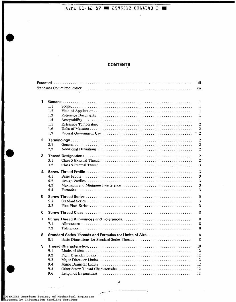
CONTENTS
... Foreword ......................................................................... u1
Standards Committee Roster .......................................................... vii
1 General .................................................................... 1 1.1 Scope ................................................................ 1 1.2 Field of Application .................................................... 1 1.3 Reference Documents .................................................. 1 1.4 Acceptability .......................................................... 1 1.5 Reference Temperature ................................................. 2 1.6 Unitsof Measure ...................................................... 2 1.7 Federal Government Use ................................................. 2
2 Terminology . . . . . . . . . . . . . . . . . . . . . . . . . . . . . . . . . . . . . . . . . . . . . . . . . . . . . . . . . . . . . . . . 2 2.1 General .............................................................. 2 2.2 Additional Definitions .................................................. 2
3 Thread Designations ........................................................ 2 3.1 Class 5 External Thread ................................................ 2 3.2 Class 5 Internal Thread .................................................. 3
4 Screw Thread Profile ........................................................ 3 4.1 Basic Profile .......................................................... 3 4.2 Design Profiles ........................................................ 3 4.3 Maximum and Minimum Interference ..................................... 3
5 Screw Thread Series ........................................................ 3 5.1 Standardseries ........................................................ 3
6 Screw Thread Class ......................................................... 8
7 Screw Thread Allowances and Tolerances ..................................... 8
7.2 Tolerances ............................................................ 8
Standard Series Threads and Formulas for Limits of Size ........................ 8.1 Basic Dimensions for Standard Series Threads .............................. 8
9 Thread Characteristics ....................................................... 10 9.1 Limits ofSize ......................................................... 12 9.2 Pitch Diameter Limits .................................................. 12 9.3 Major Diameter. Limits ................................................. 12 9.4 Minor Diameter Limits ................................................. 12 9.5 Other Screw Thread characteristics ....................................... 12 9.6 Length of Engagement .................................................. 12
4.4 Formulas ............................................................. 3
5.2 Fine Pitchseries ...................................................... 3
........................................................... 7.1 Allowances 8
8 8
ix . .
.Y . COPYRIGHT American Society of Mechanical EngineersLicensed by Information Handling ServicesCOPYRIGHT American Society of Mechanical EngineersLicensed by Information Handling Services

10 Notes on Product Design and Application ..................................... 12
10.2 External Threaded Products . . . . . . . . . . . . . . . . . . . . . . . . . . . . . . . . . . . . . . . . . . . . . . 12 10.3 Internal Threaded Products .............................................. 18 10.4 Lead and Angle Variations .............................................. 18 10.5 Cavity Space for Interference Material ..................................... 18 10.6 Thread Axis Position ................................................... 18 10.7 Surface Roughness ..................................................... 18 10.8 Lubrication . . . . . . . . . . . . . . . . . . . . . . . . . . . . . . . . . . . . . . . . . . . . . . . . . . . . . . . . . . . 20 10.9 Driving Speed . . . . . . . . . . . . . . . . . . . . . . . . . . . . . . . . . . . . . . . . . . . . . . . . . . . . . . . . . 20 10.10 20 10.11 BreaklooseTorques .................................................... 20
11.1 Gaging Systems ....................................................... 20 1 1.2
21
10.1 Conditions ofusage .................................................... 12
Relation of Driving Torque to Length of Engagement ........................
11 Product Screw Thread Acceptability .......................................... 20
Product Thread' Characteristics Conformance Requirements Over Length of Engagement for Gaging Systems 22 and 23 ...............................
12 Torque . . . . . . . . . . . . . . . . . . . . . . . . . . . . . . . . . . . . . . . . . . . . . . . . . . . . . . . . . . . . . . . . . . . . . 21
Figures 1 BasicThreadProfile . . . . . . . . . . . . . . . . . . . . . . . . . . . . . . . . . . . . . . . . . . . . . . . . . . . . . . . . . . . 4 2 Design Profile for External NC-5 HF/CSF/ONF Thread ............................. 5 3 Design Profile for Internal NC-5 IF/INF Thread .................................... 6 4 Maximum and Minimum Interference ............................................ 7 5
Threads ................................................................... 13 Illustration of LE. Ts. Tolerance of Ts. and q. Required for Assembled
Tables 1 Standard NC-5 Threadseries ................................................... 8 2 Allowances for Coarse Thread Series ............................................. 9 3
CoarseThreadSeries . . . . . . . . . . . . . . . . . . . . . . . . . . . . . . . . . . . . . . . . . . . . . . . . . . . . . . . . . 9 4 Basic Dimensions for Coarse Thread Series ........................................ 10 5 Thread Constants ............................................................. 11 6 External Thread Dimensions for Class 5 Standard .................................. 14 7 Internal Thread Dimensions for Class 5 Standard ................................... 15 8 16 9
in Functional Diameter ...................................................... 19 10
and Internal Screw Threads ................................................... 20
Tolerances for Pitch Diameter. Major Diameter. and Minor Diameter for
Interferences, Engagement Lengths, and Torques for Class 5 Standard . . . . . . . . . . . . . . . . . Maximum Allowable Variations in Lead and Maximum Equivalent Change
Maximum Allowable Variation in 30 deg . Basic Half-Angle of External
11 Working Gages . . . . . . . . . . . . . . . . . . . . . . . . . . . . . . . . . . . . . . . . . . . . . . . . . . . . . . . . . . . . . . . 22 12 Setting Gages . . . . . . . . . . . . . . . . . . . . . . . . . . . . . . . . . . . . . . . . . . . . . . . . . . . . . . . . . . . . . . . . 25
Appendices A Obsolete Tentative Standard and Alternate Standard for Class 5
Interference-Fit Thread . . . . . . . . . . . . . . . . . . . . . . . . . . . . . . . . . . . . . . . . . . . . . . . . . . . . . . 27 A l Introduction . . . . . . . . . . . . . . . . . . . . . . . . . . . . . . . . . . . . . . . . . . . . . . . . . . . . . . . . . . 27 A2 Tentative Standard . . . . . . . . . . . . . . . . . . . . . . . . . . . . . . . . . . . . . . . . . . . . . . . . . . . . . 27 A3 Alternate Standard . . . . . . . . . . . . . . . . . . . . . . . . . . . . . . . . . . . . . . . . . . . . . . . . . . . . . 27
X
/-- I
COPYRIGHT American Society of Mechanical EngineersLicensed by Information Handling ServicesCOPYRIGHT American Society of Mechanical EngineersLicensed by Information Handling Services

. ~~
ASME B 1 - 1 2 87 W 2575512 0011342 7 W
B Specifications for Elastic Interference-Fit Thread ............................... 43 B1 Introduction . . . . . . . . . . . . . . . . . . . . . . . . . . . . . . . . . . . . . . . . . . . . . . . . . . . . . . . . . . 43 B2 Thread Designation . . . . . . . . . . . . . . . . . . . . . . . . . . . . . . . . . . . . . . . . . . . . . . . . . . . . 43 B3 External and Internal Threads Compared to NC-5 ........................... 43 B4 44 B5 Gaging . . . . . . . . . . . . . . . . . . . . . . . . . . . . . . . . . . . . . . . . . . . . . . . . . . . . . . . . . . . . . . 45
Class 5 Modified Specifications for Plastic Flow Interference-Fit Thread With Addition of K Monel External Thread .............................. 49 C1 Introduction . . . . . . . . . . . . . . . . . . . . . . . . . . . . . . . . . . . . . . . . . . . . . . . . . . . . . . . . . . 49
C3 Threads . . . . . . . . . . . . . . . . . . . . . . . . . . . . . . . . . . . . . . . . . . . . . . . . . . . . . . . . . . . . 49
C4 Torque and Length of Engagement . . . . . . . . . . . . . . . . . . . . . . . . . . . . . . . . . . . . . . . . 50 C5 50 C6 Gaging . . . . . . . . . . . . . . . . . . . . . . . . . . . . . . . . . . . . . . . . . . . . . . . . . . . . . . . . . . . . . . 50
Comparison of Interference Metal for the Thread Assemblies Tabulated in the Appendices With the American National Standard Class 5 Thread Assemblies . . . . . . . . . . . . . . . . . . . . . . . . . . . . . . . . . . . . . . . . . . . . . . . . . . 55
D2 55
Application Practice for New and Reworked External and Internal Threads . . . . . . .
C
C2 Additions to Thread Designation Letters . . . . . . . . . . . . . . . . . . . . . . . . . . . . . . . . . . . 49 External and Internal Threads Compared to ASME/ANSI B1.12 Class 5
Application Practice for New and Reworked External and Internal Threads . . . . . . .
D
D1 Explanation for Table D1 . . . . . . . . . . . . . . . . . . . . . . . . . . . . . . . . . . . . . . . . . . . . . . . 55 Formulas for Volume of Interference Metal per Turn .........................
Figures A l
A2
A3
A4
A5
Illustration of Tolerances. Allowances. and Crest Clearances for Tentative
Illustration of Loosest Condition for Tentative Class 5 Wrench Fit for
Illustration of Tightest Condition for Tentative Class 5 Wrench Fit for
Illustration of Loosest Condition for Alternate Class 5 Fit for Threaded
Illustration of Tightest Condition for Alternate Class 5 Fit for Threaded
and Alternate Class 5 Fit for Threaded Studs . . . . . . . . . . . . . . . . . . . . . . . . . . . . . . . . . . . . 28
Threaded Studs. I/z in., 13 Threads. Set in Hard Materials .......................... 29
Threaded Studs. */z in., 13 Threads. Set in Hard Materials .......................... 29
34
34
Studs. Yz in., 13 Threads. Set in Hard Materials ..................................
Studs. '/z in., 13 Threads. Set in Hard Materials ..................................
Tables A l Tentative Class 5 Wrench Fit for Threaded Studs. Allowances and
Tolerances for Studs and Tapped Holes. Coarse Threaded Studs Set in HardMaterials . . . . . . . . . . . . . . . . . . . . . . . . . . . . . . . . . . . . . . . . . . . . . . . . . . . . . . . . . . . . . 30
Tolerances for Studs and Tapped Holes. Fine Threaded Studs Set in HardMaterials . . . . . . . . . . . . . . . . . . . . . . . . . . . . . . . . . . . . . . . . . . . . . . . . . . . . . . . . . . . . . 31
National Coarse Thread Series. Steel Studs Set in Hard Materials (Cast Iron. Semisteel. Bronze. etc.) .................................................
National Fine Thread Series. Steel Studs Set in Hard Materials (Cast
Alternate Class 5 Fit for Threaded Studs. Allowances and Tolerances for
Alternate Class 5 Fit for Threaded Studs. Allowances and Tolerances for
A2 Tentative Class 5 Wrench Fit for Threaded Studs. Allowances and
A3 Limiting Dimensions for Tentative Class 5 Wrench Fit for American
32 A4 Limiting Dimensions for Tentative Class 5 Wrench Fit for American
Iron. Semisteel. Bronze. etc.). ................................................
Studs and Tapped Holes. Coarse Threaded Studs Set in Hard Materials . . . . . . . . . . . . . . .
Studs and Tapped Holes. Fine Threaded Studs Set in Hard Materials . . . . . . . . . . . . . . . . .
33
35
35
A5
A6
xi
COPYRIGHT American Society of Mechanical EngineersLicensed by Information Handling ServicesCOPYRIGHT American Society of Mechanical EngineersLicensed by Information Handling Services

ASME B I - 3 2 8 7 W 2575532 0 0 3 3 3 4 3 7
A7
A8
A9
A10
Al 1
A12
B1 B2 B3
B4 c 1
c 2
c 3 c 4 D1
Limiting Dimensions for Alternate Class 5 Fit, American National Coarse Thread Series, Steel Studs Set in Hard Materials (Cast Iron, Semisteel, Bronze, etc.) . . . . . . . . . . . . . . . . . . . . . . . . . . . . . . . . . . . . . . . . . . . . . . . . . . . . . . . . . . . . . . . 36
Thread Series, Steel Studs Set in Hard Materials (Cast Iron, Semisteel, Bronze,etc.) . . . . . . . . . . . . . . . . . . . . . . . . . . . . . . . . . . . . . . . . . . . . . . . . . . . . . . . . . . . . . . . 37
Limiting Dimensions of Setting Plug and Thread Working Gages and Plain Diameter Gages for Alternate Class 5 Fit Threaded Studs, American National Coarse Thread Series . . . . . . . . . . . . . . . . . . . . . . . . . . . . . . . . . . . . . . . . . . . . . . . .
Limiting Dimensions of Thread Working Gages and Plain Diameter Gages for Alternate Class 5 Fit Tapped Holes, American National Coarse Thread Series . . . . . . . . . . . . . . . . . . . . . . . . . . . . . . . . . . . . . . . . . . . . . . . . . . . . . . . . . . . . . . 39
Diameter Gages for Alternate Class 5 Fit Threaded Studs, American National FineThread Series . . . . . . . . . . . . . . . . . . . . . . . . . . . . . . . . . . . . . . . . . . . . . . . . . . 40
Limiting Dimensions of Thread Working Gages and Plain Diameter Gages for Alternate Class 5 Fit Tapped Holes, American National Fine Thread Series . . . . . . . . . . . . . . . . . . . . . . . . . . . . . . . . . . . . . . . . . . . . . . . . . . . . . . . . . . . . . . . . . . . . . 41
46 46
47 48
Aluminum (KMonel) . . . . . . . . . . . . . . . . . . . . . . . . . . . . . . . . . . . . . . . . . . . . . . . . . . . . . . . 50
Space . . . . . . . . . . . . . . . . . . . . . . . . . . . . . . . . . . . . . . . . . . . . . . . . . . . . . . . . . . . . . . . . . . . . . 51 52 53
Turn . . . . . . . . . . . . . . . . . . . . . . . . . . . . . . . . . . . . . . . . . . . . . . . . . . . . . . . . . . . . . . . . . . . . . 56
Limiting Dimensions for Alternate Class 5 Fit, American National Fine
38
Limiting Dimensions of Setting Plug and Thread Working Gages and Plain
External Thread Dimensions for NC-5 HFM. ...................................... Internal Thread Dimensions for NC-5 IFM . . . . . . . . . . . . . . . . . . . . . . . . . . . . . . . . . . . . . . . . Engagement Length, Hole Depth, Interference, and Torque for NC-5
HFM and NC-5 IFM . . . . . . . . . . . . . . . . . . . . . . . . . . . . . . . . . . . . . . . . . . . . . . . . . . . . . . . . Setting Gages for NC-5 HFM and NC-5 IFM. . . . . . . . . . . . . . . . . . . . . . . . . . . . . . . . . . . . . . External Thread Dimensions for Class 5 Modified for Nickel-Copper-
External Thread Dimensions for Class 5 Modified for Greater Cavity
Internal Thread Dimensions for Class 5 Modified. .................................. Interference on Pitch Diameter for Class 5 Modified ................................ Thread Assemblies Compared by Percentage of Interference Metal per
-
xii
COPYRIGHT American Society of Mechanical EngineersLicensed by Information Handling ServicesCOPYRIGHT American Society of Mechanical EngineersLicensed by Information Handling Services

ASMElANSl B1.12-1987
CLASS 5 INTERFERENCE-FIT THREAD
1 GENERAL
1.1 Scope
This Standard provides dimensional tables for exter- nal and internal plastic flow interference-fit (Class 5 ) threads of modified National thread form in the coarse thread series (NC) in sizes 0.250 in. through 1.500 in. This is not the ANSI B1.l UN thread form. It is in- tended that designs conforming with this Standard will provide adequate torque conditions which fall within the limits shown in Table 8. The minimum torques are in- tended to be sufficient to insure that externally threaded members will not loosen in service; the maximum torques establish a ceiling below which seizing, galling, or torsional failure of the externally threaded compo- nents is reduced. This Standard provides for the maxi- mum allowable interference.
Appendices A, B, C , and D contain useful informa- tion that is supplementary to this Standard, such as re- prints of the obsolete tentative and alternate Class 5 standards, U.S. Navy ship specifications for elasiic in- terference-fit coarse thread series from 0.250 in. through 2.000 in., U.S. Navy ship specifications for Class 5 Modified which includes nickel-copper-aluminum al- loy external threads, and an interference metal compar- ison of standard to nonstandard interference-fit threads.
1.2 Field of Application
Interference-fit threads provide a high degree of re- sistance against turning of studs when prevailing torque nuts are used and against loosening of studs caused by load cycling and vibration. These threads are not in- tended for use where regular removal for component maintenance is required.
1.3 Reference Documents
1.3.1 American National Standards. The latest issues of the following standards form a part of this Standard to the extent specified herein.
ANSI B1.l Unified Inch Screw Threads (UN and UNR Thread Form) ANWASME B1.2 Gages and Gaging for Unified Inch Screw Threads ANWASME B 1.3M Screw Thread Gaging Systems for Dimensional Ac- ceptability-Inch and Metric Screw Threads (UN, UNR, UNJ, M, and MJ) ANSUASME B1.7M Nomenclature, Definitions, and Letter Symbols for Screw Threads ANSI B94.9 Taps-Cut and Ground Threads
1.3.2 Other References Metal Cutting Tool Institute. ’ Taps, Ground Thread,
Standards and Dimensions. Cleveland, 1983. Socieiy of Manufacturing Engineers.2 Tool and Manu-
facturing Engineers Handbook- Volume 1, Machin- ing.
American Society for metal^.^ Metals Handbook-Vol- ume 3, Machining.
Metal Cutting Tool Institute. ’ Metal Cutting Tool Hand- book.
Waltermire, W. G. “New Class 5 Interference Fit Thread.” Machine Design (September 6, 1956): 83- 96.
1 .4 Acceptability
Acceptability of product screw threads, based on the gaging method specified, shall be in accordance with ANWASME B1.3M. Gages and gaging are in accor- dance with ANSI/ASME B1.2 but with gaging dimen- sions as specified in Tables 11 and 12. See paras. 11.1.1, 11.1.2, and 11.1.3.
‘1230 Keith Building, CIeveland, Ohio 44115-2180. ‘One SME Drive, P.O. Box 930, Dearborn, Michigan 48128. 3Metals Park, Ohio 44073.
1
COPYRIGHT American Society of Mechanical EngineersLicensed by Information Handling ServicesCOPYRIGHT American Society of Mechanical EngineersLicensed by Information Handling Services

.~
ASME BI-I2 87 U 2575512 0011345 2 i
ASMElANSl 81.12-1987 CLASS 5 INTERFERENCE-FIT THREAD
1.5 Reference Temperature
sions listed. The reference temperature is 68°F (20°C) for dimen-
1.6 Units of Measure
All dimensions and values are expressed in inches un- less otherwise noted.
1.7 Federal Government Use
When this Standard is approved by the Department of Defense and federal agencies and is incorporated into FED-STD-H28/23, Screw Thread Standards for Federal Services, Section 23, the use of this Standard by the federal government will be subject to all requirements and limitations of FED-STD-H28/23.
Appendices B and C are standard for U S . Navy ship use.
2 TERMINOLOGY
2.1 General
For definitions, terms, and symbols relating to screw threads. see ANSI/ASME B1.7M.
2.2 Additional Definitions
breakaway or breakloose torque - torque required to start disassembly of the prevailing torque nut, or torque required to start disassembly of stud from internal threaded part Class 5fit - an interference-fit thread class used for in- terchangeable threaded members which are to be assem- bled by a turning force elastic interference - an interference-fit assembly where the interference material zone is stressed within elastic limits. Upon disassembly, the thread profile usu- ally has not been distorted. ferrous material - iron and steel galling - fracturing and tearing of the alloying mating surfaces and displacement of fractured metal particles during assembly or disassembly, caused by lack of lu- brication, frictional heat, poor geometry of threads, and surface welding lubricant - a liquid, powder, or mixture of both which permits assembly with a minimum of galling
lute - an ingredient of a lubricant such as graphite, rubber, white lead, molybdenum disulfide, or zinc dust inmiinurn driving torque - the maximum assembly torque derived from past experimentation which pre- vents torsional external thread failure ininimum driving torque - the minimum assembly torque for an acceptable assembly based on a torque which is 50% larger than the breakaway torque of the prevailing torque nut plastic Jlow interference - an interference-fit assembly where part of the interference zone materials are per- manently displaced beyond elastic limits. The external thread material tends to flow mostly toward its major diameter and the internal thread material tends to flow toward the minor diameter. resin sealer - an anaerobic plastic cement used to glue and lock the assembly together where service tempera- tures do not exceed 200°F and interference tolerances are not met, where fire safety is not a factor, or where UN Class 3A and 3B threads are used sealer - a lubricant which is insoluble in the medium being used torque - the force required for rotation of the screw multiplied by the perpendicular distance from the axis of the screw (expressed in pound-inches or pound-feet)
3 THREAD DESIGNATIONS
The following examples of external and internal thread designations provide the means for distinguishing the present standard Class 5 thread from the obsolete tentative and alternate American National Class 5 threads which are given in Appendix A.
NOTE: ANSIlASME B1.3M permits gaging systems to be designated in general notes, purchasing specifications, company standards, etc., in which case the individual designation of the thread designation may be omitted.
3.1 Class 5 External Thread
3.1 .I For Driving in Hard Ferrous Material With Brinell Hardness Over 160 HB
EXAMPLE: 0.500-13 NC-5 HF ( ) where
0.500 = 13 = N = C = 5 =
HF = ( ) =
2
nominal size threads per inch American National thread form coarse thread series Class 5 American National tolerance hard ferrous material, external thread System 21, 22, o r 2 3
COPYRIGHT American Society of Mechanical EngineersLicensed by Information Handling ServicesCOPYRIGHT American Society of Mechanical EngineersLicensed by Information Handling Services
CLASS 5 INTERFERENCE-FIT THREAD
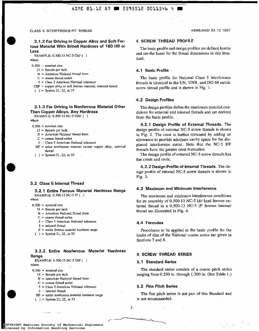
3.1.2 For Driving in Copper Alloy and Soft Fer- rous Material With Brinell Hardness of 160 HB or Less
where EXAMPLE: 0.500-13 NC-5 CSF ( )
0.500 = nominal size 13 = threads per inch N = American National thread form C = coarse thread series 5 = Class 5 American National tolerance
CSF = copper alloy or soft ferrous material, external thread ( ) = System21, 22, or23
3.1.3 For Driving in Nonferrous Material Other Than Copper Alloys, Any Hardness
where EXAMPLE: 0.500-13 NC-5 ONF ( )
0.500 = nominal size 13 = threads per inch N = American National thread form C = coarse thread series 5 = Class 5 American National tolerance
NF = other nonferrous material except copper alloy, external
( ) = System 21, 22, or 23 thread
3.2 Class 5 Internal Thread
3.2.1 Entire Ferrous Material Hardness Range EXAMPLE 0.500-13 NC-5 IF ( )
where
0.500 = nominal size 13 = threads per inch N = American National thread form C = coarse thread series 5 = Class 5 American National tolerance I = internal thread F = entire ferrous material hardness range
( ) = Sysfem21,22, or23
3.2.2 Entire Nonferrous Material Hardness Range
EXAMPLE: 0.500-13NC-5 INF ( ) where
0.500 = nominal size 13 = threads per inch N = American National thread form C = coarse threadseries 5 = Class 5 American National tolerance I = internai thread
NF = entire nonferrous material hardness range ( ) = System21,22, or23
3
ASME/ANSI B I .I 2-1 987
4 SCREW THREAD PROFILE
The basic profile and design profks are defined herein and are the bases for the thread dimensions in this Stan- dard.
4.1 Basic Profile
The basic profile for National Class 5 interference threads is identical to the UN, UNR, and IS0 68 metric screw thread profile and is shown in Fig. 1.
4.2 Design Profiles
The design profiles define the maximum material con- ditions for external and internal threads and are derived from the basic profile.
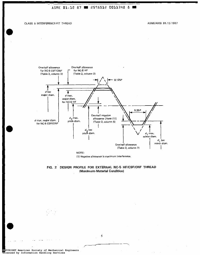
4.2.1 Design Profile of External Threads. The design profile of external NC-5 screw threads is shown in Fig. 2. The crest is further truncated by adding an allowance to provide adequate cavity space for the dis- placed interference metal. Note that the NC-5 HF threads have the greater crest truncation.
The design profile of external NC-5 screw threads has flat crests and roots.
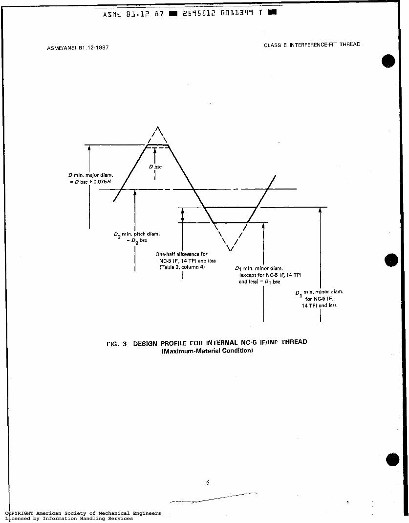
4.2.2 Design Profile of Internal Threads. The de- sign profile of internal NC-5 screw threads is shown in Fig. 3.
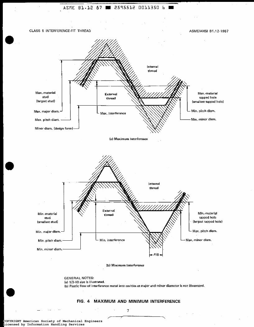
4.3 Maximum and Minimum Interference
The maximum and minimum interference conditions for an assembly of 0.500-13 NC-5 HF hard ferrous ex- ternal thread in a 0.500-13 NC-5 IF ferrous internal thread are illustrated in Fig. 4.
4.4 Formulas
Procedures to be applied to the basic profile for the limits of size of the National coarse series are given in Sections 7 and 8.
5 SCREW THREAD SERIES
5.1 Standard Series
The standard series consists of a coarse pitch series ranging from 0.250 in. through 1.500 in. (See Table 1.)
5.2 Fine Pitch Series
The fine pitch series is not part of this Standard and is not recommended.
COPYRIGHT American Society of Mechanical EngineersLicensed by Information Handling ServicesCOPYRIGHT American Society of Mechanical EngineersLicensed by Information Handling Services

ASME E L - 1 2 87 m 2575532 CIOLL347 b m
ASME/ANSI BI .12-1987
Internal threads
CLASS 5 INTERFERENCE-FIT THREAD
0.125H o-- 0.125P
A
t 4
60 deg.
30 deg.
0.500P
\ 0.250 H
-
D1 bsc,dl bsc
90 deg. I Axis of screw thread -
D2 bsc, d2 bsc
I
External threads
H = ( 6 / 2 ) P = 0.866 025P 0.125H = 0.108 253P 0.250H = 0.21 6 506P 0.375H = 0.324 760P 0.625H = 0.541 266P
FIG. 1 BASIC THREAD PROFILE
COPYRIGHT American Society of Mechanical EngineersLicensed by Information Handling ServicesCOPYRIGHT American Society of Mechanical EngineersLicensed by Information Handling Services
CLASS 5 INTERFERENCE-FIT THREAD
One-half allowance One-half allowance for NC-5 CSF/ONF for NC-5 HF (Table 2, column 3) r (Table 2, column 2)
ASME/ANSI B I .12-1987
One-half negative allowance [Note (I)] (Table 2, column 6) d max. major diam.
for NC-5 CSF/ONF
One-half allowance (Table 2, column 7)
NOTE: (1) Negative allowance i s maximum interference.
FIG. 2 DESIGN PROFILE FOR EXTERNAL NC-5 HF/CSF/ONF THREAD (Maximum-Material Condition)
COPYRIGHT American Society of Mechanical EngineersLicensed by Information Handling ServicesCOPYRIGHT American Society of Mechanical EngineersLicensed by Information Handling Services
ASMElANSl 61.12-1 987
ASME BI-32 87 W 2595532 0033344 T
CLASS 5 INTERFERENCE-FIT THREAD
9 1 NC-5 IF, 14 TPI and less (Table 2, column 41 D1 min. minor d im.
(except for NC-5 IF, 14 TPI and less) = D1 bsc
I D min. minor diam.
for NC-5 IF. 14 TPI and less
FIG. 3 DESIGN PROFILE FOR INTERNAL NC-5 IF/INF THREAD (Maximum-Material Condition)
3
COPYRIGHT American Society of Mechanical EngineersLicensed by Information Handling ServicesCOPYRIGHT American Society of Mechanical EngineersLicensed by Information Handling Services
ASME BI-12 87 m 2575532 003L350 b
CLASS 5 INTERFERENCE-FIT THREAD
Maxmaterial stud
(largest stud)
Max. major diam.
Max. pitch diam.
Minor diam. (design form)
Max. interference
ASMElANSl BT.12-1987
Max.-material tapped hole
(smallest tapped hole)
Min. pitch diam.
Min. minor diam.
(a) Maximum Interference
Internal
Min.-material tapped hole
(largest tapped hole)
Max. pitch diam. Min. major diam.
Max. minor diam. Min. interference
Min. minor diam.
(b) Minimum Interference
GENERAL NOTES: (a) 1/2-13 size is illustrated. (b) Plastic flow of interference metal into cavities at major and minor diameter i s not illustrated.
FIG. 4 MAXIMUM AND MINIMUM INTERFERENCE
7
COPYRIGHT American Society of Mechanical EngineersLicensed by Information Handling ServicesCOPYRIGHT American Society of Mechanical EngineersLicensed by Information Handling Services

ASME/ANSI 81.12-1987 CLASS 5 INTERFERENCE-FIT THREAD
TABLE 1 STANDARD NC-5 THREAD SERIES
'h-20 or 0.2500-20
3/~-16 or 0.3750-16 %S-14 or 0.4375-14 %-i3 or 0.5000-13 9/16-1 2 or 0.5625-1 2 5i~-11 or 0.6250-11
'/i6-18 or 0.3125-18 3/4-10 or 0.7500-10 l / ~ - 9 or 0.8750- 9
1 - 8 or 1.0000- 8 1%- 7 or 1.1250- 7 1%- 7 or 1.2500- 7 13/8- 6 or 1.3750- 6 1%- 6 or 1.5000- 6
6 SCREW THREAD CLASS
The Class 5 interference fit was originally published as tentative by the National Screw Thread Commission in 1928. Over the years, some of the tolerances, diam- eters, and negative allowances (maximum interferences) have been modified in accordance with industry re- search.
7 SCREW THREAD ALLOWANCES AND TOLERANCES
7.1 Allowances
7.1 .I Pitch Diameter Allowance. A negative al- lowance (maximum pitch diameter interference) at max- imum material is specified for the Class 5 external thread. Its purpose is to provide interference metal-to- metal contact to provide very high resistance to disas- sembly of the mated thread. (See Table 2.) There is no formula to generate the allowance.
7.1.2 Crest and Root Allowances. Crest and root allowances, tabulated in Table 2, such as differences be- tween nominal size and maximum major diameter for external thread, between nominal size and minimum major diameter for internal thread (see General Notes to Table 2), between basic minor diameter and minimum minor diameter for internal thread, and between maxi- mum minor diameter and basic minor diameter for ex- ternal thread, provide cavity space at the major and minor diameters of Class 5 threads. These allowances are intended to reduce installation torques. These cavi- ties accept displaced material from thread flank inter- ference. (See para. 10.5.)
7.2 Tolerances
7.2.1 Pitch Diameter Tolerance. The pitch diam- eter tolerance for both internal and external threads is the same as for National Class 3. (See Table 3.) There
is no formula to generate the National Class 3 pitch di- ameter tolerance.
7.2.2 Major Diameter Tolerance 7.2.2.1 External Threads. The major diameter
tolerance for all external threads is twice the National Class 3 pitch diameter tolerance. (See Table 3 .)
7.2.2.2 Internal Threads. The major diameter limits for all internal threads are the limits published by the Metal Cutting Tool Institute for the major diameter for ground thread taps, and are given in this Standard as a reference for the internal thread major diameter. These limits are used in the design of the tools that produce the internal thread major diameter. Acceptance of the internal thread major diameter is by the acceptance of the thread by a maximum material GO thread gage. (See Table 3 for tap major diameter tolerance.)
7.2.3 Minor Diameter Tolerance. The minor di- ameter tolerances for internal threads are tabulated in Table 3. For NC-5 IF threads with 20 through 16 TPI and 6 through 4 TPI, and for all NC-5 INF threads, the minor diameter tolerances are those for National Class 3 internal minor diameter rounded to three decimal places. Minor diameter tolerances for the remaining threads for NC-5 IF are one-sixth of 3/4H or 0.125H rounded to three decimal places.
8 STANDARD SERIES THREADS AND FORMULAS FOR LIMITS OF SIZE
8.1 Basic Dimensions for Standard Series Threads
The standard series for National Class 5 screw threads is listed in Table 1. Basic dimensions are given for coarse thread series in Table 4. Thread form data is given in Table 5. The limits of size are established by applying tolerances and allowances to the basic dimen- sions as indicated. These limits are the basis for mea- suring and gaging of the thread.
COPYRIGHT American Society of Mechanical EngineersLicensed by Information Handling ServicesCOPYRIGHT American Society of Mechanical EngineersLicensed by Information Handling Services

ASME 81-12 87 = 2575532 0033352 T M
CLASS 5 INTERFERENCE-FIT THREAD ASME/ANSI B I . 12-1 987
TABLE 2 ALLOWANCES FOR COARSE THREAD SERIES
Difference Between
Max. Minor Diam. and
Basic Minor Diam.,
External Thread
Difference Between Nominal
Size and Max. Major Diam. of NC-5 CSF or
[Note (1 )I NC-5 ONF
Difference Eetween Basic
Minor Diam. and Min.
Minor Diam. of
[Note (1 )I NC-5 IF
Maximum PD Interference or
Negative Allowance,
External Thread
[Note (2i1
Difference Between Nominal
Size and Max. Major Diam. of
[Note (1 )I NC-5 HF
Difference Between Basic Minor Diam.
and Min. Minor Diam. of
NC-5 INF TPI
1 2 3 4 5 6 7
20 18 16 14
13 12 11 10
9 8 7 6
0.0030 0.0045 0.0060 0.0070
0.0080 0.0085 0.01 10 0.0140
0.01 50 0.01 65 0.01 80 0.01 90
0.0030 0.0035 0.0040 0.0045
0.0050 0.0050 0.0055 0.0060
0.0065 0.0065 0.0070 0.0070
0.000 0.000 0.000 0.01 4
0.014 0.01 6 0.01 7 0.01 9
0.022 0.025 0.030 0.034
0.000 0.000 0.000 0.000
0.000 0.000 0.000 0.000
0.000 0.000 0.000 0.000
0.0055 0.0065 0.0070 0.0080
0.0084 0.0092 0.0098 0.0105
0.01 16 0.01 28 0.0143 0.01 72
0.0072 0.0080 0.0090 0.0103
0.01 11 0.01 20 0.0131 0.0144
0.01 60 0.01 80 0.0206 0.0241
GENERAL NOTE: The difference between basic major diameter and internal thread minimum major diameter is 0.075H and is tabulated in Table 3, column 6.
NOTES: (1 ) The allowance values in columns 2, 3, and 4 were obtained from industrial research data. (2) Negative allowance is the difference between the basic pitch diameter and the pitch diameter value at maximum material.
TABLE 3 TOLERANCE§ FOR PITCH DIAMETER, MAJOR DIAMETER, AND MINOR DIAMETER FOR COARSE THREAD SERIES
Minor Diameter Tolerance for
Internal Thread
[Note (311 NC-5 INF
Tolerance 0.075H or
0.065P for Tap
Major Diameter
Pitch Diameter Tolerance for External and
Internal Thread [Note (111
Major Diameter Tolerance for
External Thread [Note (2)I
Minor Diameter Tolerance for
Internal Thread NC-5 IF TPI
1 2 3 4 5 6
20 18 16 14
13 12 11 10
9 8 7 6
0.0026 0.0030 0.0032 0.0036
0.0037 0.0040 0.0042 0.0045
0.0049 0.0054 0.0059 0.0071
0.0052 0.0060 0.0064 0.0072
0.0074 0.0080 0.0084 0.0090
0.0098 0.0108 0.01 18 0.0142
~
0.010 0.01 1 0.01 1 0.008
0.008 0.009 0.010 0.01 1
0.01 2 0.014 0.01 5 0.018
~ ~~
0.010 0.01 1 0.01 1 0.01 2
0.01 2 0.01 3 0.01 3 0.014
0.01 4 0.01 5 0.01 5 0.01 8
0.0032 0.0036 0.0041 0.0046
0.0050 0.0054 0.0059 0.0065
0.0072 0.0081 0.0093 0.01 08
NOTES: (1) National Class 3 pitch diameter tolerance from ASA B I .l-1960 (see p. 85). (2) Twice the NC-3 pitch diameter tolerance. (3) National Class 3 minor diameter tolerance from ASA B I .I-1960 (see p. 85)
COPYRIGHT American Society of Mechanical EngineersLicensed by Information Handling ServicesCOPYRIGHT American Society of Mechanical EngineersLicensed by Information Handling Services
ASME B3*32 87 2575532 0033353 3
ASMElANSl BI. 12-1 987 CLASS 5 INTERFERENCE-FIT THREAD
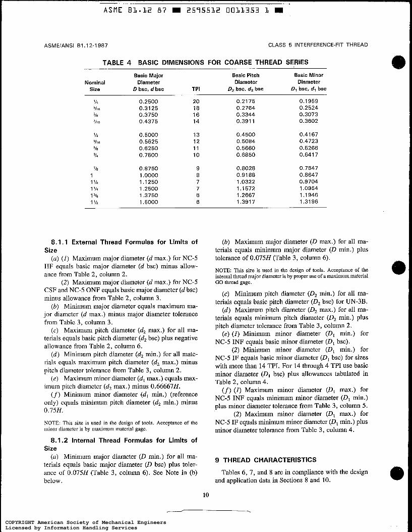
TABLE 4 BASIC DIMENSIONS FOR COARSE THREAD SERIES
Basic Major Basic Pitch Basic Minor Nominal Diameter Diameter Diameter
Size D bsc, d bsc TPI 0 2 bsc, d2 bsc D1 bsc. dq bsc
0.2500 0.31 25 0.3750 0.4375
0.5000 0.5625 0.6250 0.7500
0.8750 1 .oooo 1.1250 1.2500 1.3750 1.5000
20 18 16 14
13 12 1 1 10
9 8 7 7 6 6
0.21 75 0.2764 0.3344 0.391 1
0.4500 0.5084 0.5660 0.6850
0.8028 0.9188 1.0322 1 .I 572 1.2667 1.391 7
0.1959 0.2524 0.3073 0.3602
0.41 67 0.4723 0.5266 0.641 7
0.7547 0.8647 0.9704 1 .OS54 1.1946 1.3196
8.1.1 External Thread Formulas for Limits of Size
(a) (1) Maximum major diameter (d max.) for NC-5 HF equals basic major diameter (d bsc) minus allow- ance from Table 2, column 2.
(2 ) Maximum major diameter (d max.) for NC-5 CSF and NC-5 ONF equals basic major diameter (d bsc) minus allowance from Table 2, column 3.
(b) Minimum major diameter equals maximum ma- jor diameter (d max.) minus major diameter tolerance from Table 3, column 3.
(c) Maximum pitch diameter (d2 max.) for all ma- terials equals basic pitch diameter (d2 bsc) plus negative allowance from Table 2, column 6.
(d ) Minimum pitch diameter (d2 min.) for all mate- rials equals maximum pitch diameter (d2 max.) minus pitch diameter tolerance from Table 3, column 2.
( e ) Maximum minor diameter (d, max.) equals max- imum pitch diameter (d2 max.) minus 0.666678. (f) Minimum minor diameter (d, min.) (reference
only) equals minimum pitch diameter (d2 min.) minus 0.75H.
NOTE: This size is used in the design of tools. Acceptance of the minor diameter is by maximum material gage.
8.1.2 Internal Thread Formulas for Limits of Size
(a) Minimum major diameter (D min.) for all ma- terials equals basic major diameter (D bsc) plus toler- ance of 0.075H (Table 3, column 6). See Note in (b) below.
(b) Maximum major diameter (D max.) for all ma- terials equals minimum major diameter (D min.) plus tolerance of 0.0758 (Table 3, column 6).
NOTE: This size is used in the design of tools. Acceptance of the internal thread major diameter is by proper use of a maximum material GO thread gage.
(c) Minimum pitch diameter (D2 rnin.) for all ma- terials equals basic pitch diameter (D2 bsc) for UN-3B.
(d) Maximum pitch diameter (D2 max.) for all ma- terials equals minimum pitch diameter (D2 min.) plus pitch diameter tolerance from Table 3, column 2.
(e ) (1) Minimum minor diameter (D, min.) for NC-5 INF equals basic minor diameter (D, bsc).
(2) Minimum minor diameter (D, rnin.) for NC-5 IF equals basic minor diameter (D, bsc) for sizes with more than 14 TPI. For 14 through 4 TPI use basic minor diameter (D, bsc) plus allowances tabulated in Table 2, column 4. (f) ( I ) Maximum minor diameter (D, max.) for
NC-5 INF equals minimum minor diameter (D, rnin.) plus minor diameter tolerance from Table 3, column 5.
(2) Maximum minor diameter (D, max.) for NC-5 IF equals minimum minor diameter (D, mh.) plus minor diameter tolerance from Table 3, column 4.
9 THREAD CHARACTERISTICS
Tables 6, 7, and 8 are in compliance with the design and application data in Sections 8 and 10.
10
COPYRIGHT American Society of Mechanical EngineersLicensed by Information Handling ServicesCOPYRIGHT American Society of Mechanical EngineersLicensed by Information Handling Services
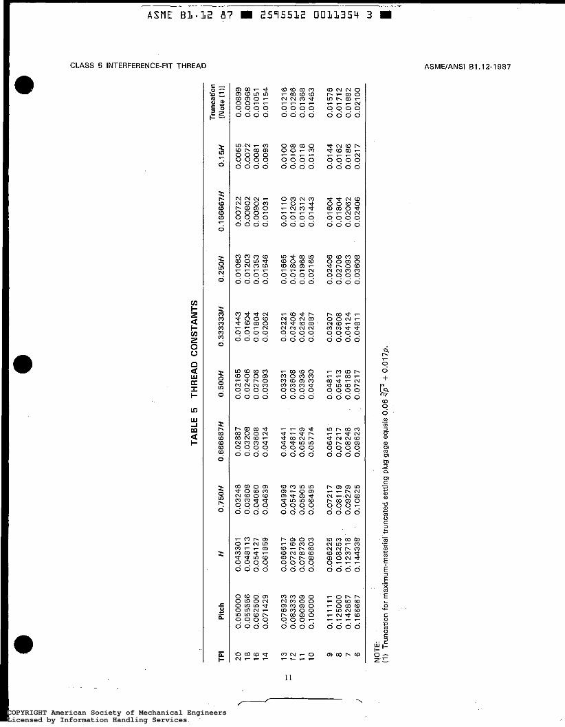
TAB
LE 5
TH
RE
AD
CO
NS
TAN
TS
I
Trun
catio
n TP
I P
itch
H
0.75
0H
0.66
6667
H
0.5
00
H
0.33
3333
H
0.2
50
H
0.16
6667
H
0.1 5H
[Not
e (1
)I
20
0.05
0000
0.
0433
01
0.03
248
0,02
887
0.02
1 65
0.
01 4
43
0.01
083
0.00
722
0.00
65
0.00
899
18
0.05
5556
0.
048
1 1 3
0.03
608
0.03
208
0.02
406
0.01
604
0.
01 2
03
0.00
802
0.00
72
0.00
968
16
0.06
2500
0.
0541
27
0.04
060
0.03
608
0.02
706
0.01
804
0.01
353
0.
0090
2 0.
0081
0.
0105
1 14
0.
0714
29
0.06
1 85
9 0.
0463
9 0.
041
24
0.03
093
0.02
062
0.01
546
0.
0103
1 0.
0093
0.
01 1
54
0.01
21
6 0.
01 66
5 0.
0128
6 12
0.
0833
33
0.07
2 16
9 0.
0541
3
0.04
81 1
0.
0360
8 0.
0240
6 0.
0180
4 11
0.
0909
09
0.07
8730
0.
0590
5 0.
0524
9 0.
0393
6 0.
0262
4 0.
01 9
68
0.01
31
2 0.
01 1
8 0.
01 3
68
0.01
463
10
0.10
0000
0.
0866
03
0.06
495
0.05
774
0.04
330
0.02
887
0.02
1 65
0.
01 4
43
0.01
00
0.01
1 10
0.
0120
3 0.
0108
0.01
30
r
13
0.07
6923
0.
0666
1 7
0.04
996
0.04
441
0.03
331
0.02
221
- 9
0.1
1 1
1 1 1
0.09
6225
0.
0721
7
0.06
41 5
0.
0481
1
0.03
207
0.02
406
0.01
44
0.01
576
0.
01 6
04
8 0.
1250
00
0.10
8253
0.
081
19
0.07
217
0.05
41 3
0.
0360
8 0.
01 8
04
0.01
62
0.01
712
0.02
706
7 0.
1428
57
0.1
2371
8 0.
0927
9 0.
0824
8 0.
061
86
0.04
1 24
0.
0309
3 0.
0206
2 0.
01 8
6 0.
01 8
82
0.04
81 1
0.
0360
8 0.
0240
6 0.
021
7 0.
021
00
6 0.
1 66
667
0.14
4338
0.
1082
5 0.
09 6
23
0.07
21 7
NO
TE:
(1)
Tru
ncat
ion
for
max
imum
-mat
eria
l tr
unca
ted
setti
ng p
lug
gage
equ
als
0.06
+ 0
.01
7~
.
4 I
N
Ln
Jl Ln
Ln
Id N
0
0
t-l
I+ W
Ln
J=
W I
COPYRIGHT American Society of Mechanical EngineersLicensed by Information Handling ServicesCOPYRIGHT American Society of Mechanical EngineersLicensed by Information Handling Services

ASME B3*32 87 = 2575532 0011355 5 M
ASME/ANSI B1.12-1987
9 .1 Limits of Size
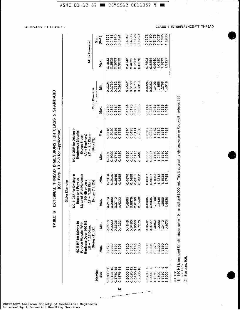
Limits of size for the national coarse series for 0.250 in. through 1 SO0 in. are given in Tables 6 and 7.
NOTE: Specifications for Class 5 Modified for K Monel external threads and usable for more materials are given in Appendix C.
9.2 Pitch Diameter Limits
9.2.1 External Thread. One set of pitch diameter limits is maintained for each size regardless of material. The minimum pitch diameter on external threads is larger than the basic pitch diameter of comparable uni- fied coarse threads.
9.2.2 Internal Thread. One set of pitch diameter limits is maintained for each size regardless of material. The minimum pitch diameter on internal threads is the same as the basic pitch diameter of comparable unified coarse threads,
9.3 Major Diameter Limits
9.3.1 External Thread (a) The major diameter of the external thread is less
than the basic major diameter, which is based on a trun- cation of H/8. This reduction provides a spiral cavity between the major diameters of the external thread and internal thread where the interference material can flow. (See para. 9.4.2.)
(b) The hard ferrous materials and materials of sim- ilar hardness have a smaller major diameter than the soft ferrous and nonferrous materials.
9.3.2 Internal Thread (a) The minimum major diameter of the internal
thread is equal to the minimum tap major diameter. [See para. 8.1.2(a).]
(b) The maximum major diameter of the internal thread is nominally equal to the maximum major di- ameter of the tap. [See para. 8.1.20>).]
9.4 Minor Diameter Limits
9.4.1 Internal Thread. The internal thread minor diameter limits are National Class 3 for all sizes in non- ferrous materials and for sizes 0.0250 in. through 0.375 in. for ferrous materials. For 0.4375 in. and larger sizes in ferrous materials, the minor diameters have been en- larged slightly in order to reduce driving torques.
9.4.2 External Thread. The maximum minor di- ameter of the external thread is less than the basic minor
CLASS 5 INTERFERENCE-FIT THREAD
diameter. This provides a cavity between the 'external and internal thread minor diameters for additional inter- ference material flow. (See para. 9.3.1 .)
9.5 Other Screw Thread Characteristics
Tables 1 and 2 in ANSUASME B1.3M identify the external and internal product screw thread characteris- tic(s), respectively, which singly or cumulatively change both the maximum and minimum interference condi- tions.
9.6 Length of Engagement
For driving into copper alloys and ferrous materials, the length of engagement is 1.250. For driving into other nonferrous materials, the length of engagement is 2.50. These are tabulated in Table 8.
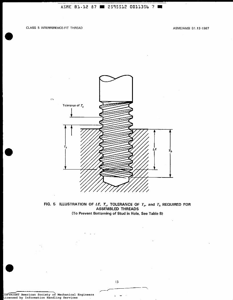
Tolerances for length of full-form external thread and for minimum depth of full-form internal thread in hole are provided because the assembled external thread shall not bottom nor shall the unfinished threads engage. False torque and excessive stress occur if one or both of the above conditions exist. (See Fig. 5.)
10 NOTES ON PRODUCT DESIGN AND APPLICATION
10.1 Conditions of Usage
The following are for plastic flow interference-fit con- ditions on which satisfactory application of products made to dimensions in Tables 6 and 7 are predicated. Deviations from the dimensions and application notes may result in unsatisfactory performance. In the manu- facture or inspection of product threads, control and ver- ification of the limits of size and the various individual thread elements, using measurement methods, ensure that the threads produced will be acceptable. (See Ap- pendix B for information on elastic interference fit.)
10.2 External Threaded Products
10.2.1 Coated Parts. Limits apply to bare or me- tallic coated parts.
10.2.2 Points. Points of externally threaded prod- ucts should be chamfered or otherwise reduced to a di- ameter below the minimum minor diameter of the thread.
12
--. COPYRIGHT American Society of Mechanical EngineersLicensed by Information Handling ServicesCOPYRIGHT American Society of Mechanical EngineersLicensed by Information Handling Services
ASME B L * 3 2 87 W 2575532 003335b 7
CLASS 5 INTERFERENCE-FIT THREAD ASME/ANSI 61.12-1987
FIG. 5 ILLUSTRATION OF LE, T,, TOLERANCE OF T,, and T,, REQUIRED FOR ASSEMBLED THREADS
(To Prevent Bottoming of Stud in Hole, See Table 8)
13
.-------
. " COPYRIGHT American Society of Mechanical EngineersLicensed by Information Handling ServicesCOPYRIGHT American Society of Mechanical EngineersLicensed by Information Handling Services
Ln
Ln
I+,
IiJ
0,
0
t-'
W
Ln 4
PI
TAB
LE 6
E
XTE
RN
AL
THR
EA
D D
IME
NS
ION
S F
OR
CLA
SS
5 S
TAN
DA
RD
(S
ee P
ara.
10
.2.3
for
App
licat
ion)
Maj
or D
iam
eter
NC
-5 C
SF f
or D
rivin
g in
B
rass
and
Fer
rous
M
ater
ial W
ith H
ardn
ess
16
0 H
B o
r Le
ss
LE =
1.2
5 D
iam
. LE
= 1
.25
Dia
m.
[Not
es (
1).
(211
NC
-5 H
F fo
r D
rivin
g in
F
erro
us M
ater
ial W
ith
Har
dnes
s O
ver
16
0 H
B
[Not
es (1
1. (
211
Nom
inal
S
ize
Max
. M
in.
Max
. M
in.
NC
-5 O
NF
for
Driv
ing
in
Non
ferr
ous
Mat
eria
l E
xcep
t Bra
ss
(Any
Har
dnes
s)
LE =
2.5
Dia
m.
Min
or D
iam
eter
[N
ote
(211
P
itch
Dia
met
er
Min
. M
ax.
Min
. M
ax.
Min
. M
ax.
(Ref
.)
0.25
00-2
0 0.
3125
-18
0.37
50-1
6
0.43
75-1
4
0.24
70
0.30
80
0.36
90
0.43
05
0.24
1 8
0.30
20
0.36
26
0.42
33
0.24
70
0.30
90
0.37
10
0.43
30
0.24
1 8
0.30
30
0.36
46
0.42
58
0.24
70
0.30
90
0.37
10
0.43
30
0.24
1 8
0.30
30
0.36
46
0.42
58
0.22
30
0.28
29
0.34
1 4
0.39
91
0.22
04
0.27
99
0.33
82
0.39
55
0.19
32
0.25
08
0.30
53
0.35
79
0.18
79
0.24
38
0.29
76
0.34
91
0.50
00-1
3
0.56
25-1
2
0.62
50-1
1
0.75
00-1
0
0.49
20
0.55
40
0.61
40
0.73
60
0.48
46
0.54
60
0.60
56
0.72
70
0.49
50
0.55
75
0.61
95
0.74
40
0.48
76
0.54
95
0.61
11
0.73
50
0.49
50
0.55
75
0.61
95
0.74
40
0.48
76
0.54
95
0.61
11
0.73
50
0.45
84
0.51
76
0.57
58
0.69
55
0.45
47
0.51
36
0.57
1 6
0.69
10
0.41
40
0.46
95
0.52
33
0.63
78
0.40
47
0.45
95
0.51
26
0.62
60
0.73
73
0.84
50
0.94
78
1.07
28
1.16
85
1.29
35
0.87
50-
9 1.
0000
- 8
1.12
50-
7 1.
2500
- 7
1.37
50-
6 1.
5000
- 6
0.86
00
0.98
35
1.10
70
1.23
20
1.35
60
1.48
10
0.85
02
0.97
27
1.09
52
1.22
00
1.34
10
1.46
70
0.86
85
0.99
35
1.11
80
1.24
30
1.36
80
1.49
30
0.85
87
0.98
27
1.10
62
1.23
1 2
1.35
38
1.47
88 '
.
0.86
85
0.99
35
1.11
80
1 .24
30
1.36
80
1.49
30
0.85
87
0.98
27
1.10
62
1.23
1 2
1.35
38
1.47
88
0.81
44
0.93
1 6
1.04
65
1.17
15
1.28
39
1.40
89
0.80
95
0.92
62
1.04
06
1.16
56
1.27
68
1.40
1 8
0.75
03
0.85
94
0.96
40
1.08
90
1.18
77
1.31
27
I
NOTES:
(1)
160
HB
is s
tand
ard
Brin
ell n
umbe
r usi
ng 1
0 m
m b
all a
nd 3
000
kgf.
Thi
s is
app
roxi
mat
ely
equi
vale
nt to
Roc
kwel
l har
dnes
s B
83
(83
HR
B).
(2)
See
par
a. 9
.6.
m a -n
rn
n
rn z 0
COPYRIGHT American Society of Mechanical EngineersLicensed by Information Handling ServicesCOPYRIGHT American Society of Mechanical EngineersLicensed by Information Handling Services

TAB
LE 7
IN
TER
NA
L TH
RE
AD
DIM
EN
SIO
NS
FO
R C
LAS
S 5
STA
ND
AR
D
(See
Par
a, 1
0.2
.3 fo
r A
pplic
atio
n)
NC
-5 IF
N
C-5
INF
Ferr
ous
Mqt
eria
l N
onfe
rrou
s M
ater
ial
Maj
or D
iam
eter
M
in.
Max
. M
in.
Max
. P
itch
Dia
met
er
, Nom
inal
M
inor
M
inor
Ta
p M
inor
M
inor
Ta
p M
ax.
Siz
e D
iam
. D
iam
. D
rill
Dia
m.
Dia
m.
Dri
ll M
in.
Max
. M
in.
[Not
e (1
11 1
0.25
00-2
0 0.
1 960
0.
2060
0.
2031
0.
1960
0.
2060
0.
2031
0.
2175
0.
2201
0.
2532
0.
2565
0.
31 25
-1 8
0.25
20
0.26
30
0.26
10
0.25
20
, 0.
2610
0.
2764
0.
2794
0.
31 6
1 0.
3197
0.
2630
0.
3759
-1 6
0.
3070
0.
3180
0.
3160
0.
3070
0.
31 8
0 0.
31 6
0 0.
3344
0.
3376
0.
3790
0.
3831
0.
4375
-1 4
0.37
40
0.38
10
0.37
50
0.36
00
0.37
20
0.36
80
0.39
1 1
0.39
47
0.44
21
0.44
68
0.43
10
0.44
00
0.43
31
0.41
70
0.42
1 9
0.45
00
0.45
37
0.50
50
0.51
00
0.42
90
0.56
25-1
2 0.
4880
0.
4970
0.
4921
0.
4720
0.
4850
0.
4844
0.
5084
0.
51 2
4 0.
5679
0.
5733
0.
6250
-1 1
0.54
40
0.55
40
0.54
69
0.52
70
0.54
00
0.53
1 3
0.
5660
0.
5702
0.
6309
0.
6368
0,
7500
-10
0.66
10
0.67
80
0.67
19
0.64
20
0.65
50
0.64
96
0.68
50
0.68
95
0.75
65
0.76
30
ei
vi
0.50
00-1
3
0.87
50-
9 0.
7770
0.
7890
0.
781
2 0.
7550
0.
7690
0.
7656
0.
8028
0.
8077
0.
8822
0.
8894
1.
0000
- 8
0.89
00
0.90
40
0.8g
06
0.86
50
0.88
00
0.87
50
0.91
88
0.92
42
1.00
81
1.01
62
1,12
50-
7 1 .
oooo
1.
01 50
1 .
oooo
0.
9700
0.
9860
0.
9844
1.
0322
I .
0381
1.
1343
1.
1436
1.
2500
- ?'
1 .I 2
so
1.14
00
1,12
50
1.09
50
1.16
31
1.25
93
1,26
86
1 .I 5
72
1.10
94
1,11
10
1.37
50- 6.
1.22
90
1,24
70
1.23
44
1.19
50
1.21
30
1.20
31
1.26
67
1.38
58
1.39
67
1.27
38
1.50
00- 6
1,35
40
1.37
20
1.35
94
1.32
00
1.33
80
1.32
81
1.39
1 7
1.39
88
1.51
08
1.52
17
NO
TE:
(11
Ref
eren
ce, m
axim
um m
ajor
dia
met
er of
tap
.
0
0
P
t.'
W
Ln
I3
0 I
COPYRIGHT American Society of Mechanical EngineersLicensed by Information Handling ServicesCOPYRIGHT American Society of Mechanical EngineersLicensed by Information Handling Services
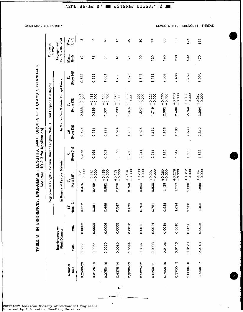
TAB
LE 8
IN
TER
FER
EN
CE
S,
EN
GA
GE
ME
NT
LEN
GTH
S,
AN
D T
OR
QU
ES
FO
R C
LAS
S 5
ST
AN
DA
RD
(S
ee P
ara.
10
.2.3
for
Ap
plic
atio
n)
Eng
agem
ent
Leng
ths,
Ext
erna
l Thr
ead
Leng
ths
[Not
e (1
11, a
nd T
appe
d H
ole
Dep
ths
Torq
ue a
t 1
.25
0
Eng
agem
ent,
Fe
rrou
s M
ater
ial
Max
., M
in.,
Inte
rfer
ence
s on
P
itch
Dia
met
er
In N
onfe
rrou
s M
ater
ial E
xcep
t B
rass
In
Bra
ss a
nd F
erro
us M
ater
ial
Nom
inal
LE
Ts
Th
LE
Ts
T
h
Siz
e M
ax.
Min
. [N
ote
(211
[N
ote
(311
[N
ote
(411
[N
ote
(211
[N
ote
(311
[N
ote
(411
Ib
-ft
Ib-f
t
0.37
5 0.
375
-0.0
00
0.25
00-2
0 0.
0055
0.
0003
0.
31 2
0.
625
+O. 1
25
o.68
8 -0
.000
0.
688
12
3
0.31
25-1
8
0.00
65
0.00
05
0.39
1 +
0.13
9 0.
469
-0.0
00
0.46
9 0.
781
0.85
9 1
9
6
0.37
50-1
6 0.
0070
0.
0006
0.
469
+O. 1
56
0.56
2 -0
.000
0.
562
0.93
8 +
0.15
6 l.
031
-0.0
00
1.03
1 3
5
10
, C
L
0.43
75-1
4 0.
0080
0.
0008
0.
547
0.65
6 Io::::
0.65
6 1.
094
1.20
3 45
1
5
+0.
179
1.20
3 -0
.000
0.50
00-1
3
0.00
84
0.00
1 0
0.62
5 0.
750
~~~~
~~
0.75
0 1.
250
1.37
5 75
20
-0
.000
f0.2
08
0.
5625
-12
0.00
92
0.00
12
0.70
3 +
o'20
8 0.
844
1.40
6 1.
547
90
30
1.54
7 -0
.000
0.
844
-0.0
00
0.62
50-1
1 0.
0098
0.
0014
0.
781
+0
'22
7
0.93
8 1.
562
1.71
9 12
0 37
1
.71
9 -
0.00
0 0.
938
-0.0
00
2.06
2 -0
.000
1.
125
-0.0
00
0.87
50-
9 0.
0116
0.
0018
1.
094
1.31
2 2.
188
+0.
278
2.40
6 25
0 90
2.
406
-0.0
00
1.31
2 -0
.000
2.75
0 -0
.000
+0.
227
0.75
00-1
0 0.
0105
0.
0015
0.
938
1.12
5 1.
875
2.06
2 19
0 60
+
0.25
0
+0.
278
1.00
00-
8 0.
0128
0.
0020
1.
250
1.50
0 2.
500
+0'
312
2.75
0 40
0 1
25
+
0.31
2 -0
.000
1.68
8 C
0.35
7 1.
688
-0.0
00
1.12
50-
7 0.
0143
0.
0025
1.
406
3.09
4 47
0 1
55
3.
094
-0.0
00
2.81
2
A
(D
CU 4
Ln - z n n
rn
n
rn z
0 'i
3
-I m
COPYRIGHT American Society of Mechanical EngineersLicensed by Information Handling ServicesCOPYRIGHT American Society of Mechanical EngineersLicensed by Information Handling Services
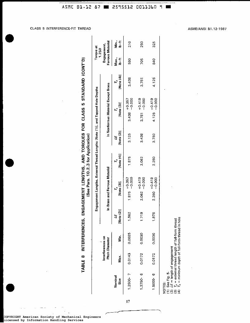
E cn
cn
cn z
z
-n
rn
20
rn z
0
? 9
-I
-I I - m
TAB
LE 8
IN
TER
FER
EN
CE
S,
EN
GA
GE
ME
NT
LEN
GTH
S,
AN
D T
OR
QU
ES
FO
R C
LAS
S 5
STA
ND
AR
D (
CO
NT
'D)
33
(See
Par
a. 1
0.2
.3 fo
r A
pplic
atio
n)
0 E
ngag
emen
t Len
gths
, E
xter
nal T
hrea
d Le
ngth
s [N
ote
(1 )I, a
nd T
appe
d H
ole
Dep
ths
Tor
que
at
I 1
.25
0
Inte
rfer
ence
s on
E
ngag
emen
t, P
itch
Dia
met
er
In B
rass
and
Fer
rous
Mat
eria
l In
Non
ferr
ous
Mat
eria
l Exc
ept
Bra
ss
Fer
rous
Mat
eria
l
Nom
inal
LE
TS
T
h
LE
Ts
Th
M
ax.,
Min
., S
ize
Max
. M
in.
[Not
e i2
i1
[Not
e i3
i1
[Not
e (4
11
[Not
e (2
i1
[Not
e i3
i1
[Not
e (4
11
Ib-f
t Ib
-ft
1.25
00-
7 0.
0143
0.
0025
1.
562
1.87
5 3.
125
+0.3
57
3.43
8 5
80
21
0 3.
438
-0.0
00
+0.3
57
-0.0
00
+0
'41
9
2.06
2 2.
062
-0.0
00
1.37
50-
6 0.
0172
0.
0030
1.
719
+0
'41
9
3.78
1 3.
781
-0.0
00
3.43
8 7
05
2
50
1.50
00-
6 0.
0172
0.
0030
1.
875
2.25
0 3.
750
+0
'41
9
4.12
5 8
40
3
25
4
.12
5
-0.0
00
+0.4
19
2.25
0 -0
.000
I N
OTE
S:
(1)
See
Fig
. 5.
(2
) LE
= le
ngth
of
enga
gem
ent
(3) T
s =
ext
erna
l thr
ead
leng
th o
f ful
l-fo
rm th
read
(4
) Th
= m
inim
um d
epth
of
full-
form
thre
ad in
hol
e
D
cn .
m z 2
COPYRIGHT American Society of Mechanical EngineersLicensed by Information Handling ServicesCOPYRIGHT American Society of Mechanical EngineersLicensed by Information Handling Services
ASME/ANSI B I . I 2-1 987
10.2.3 Materials of Externally Threaded Fer- rous Products. The length of engagement, depth of thread engagement, and pitch diameter in Tables 6 through 8 are designed to produce adequate torque con- ditions when heat-treated medium-carbon steel prod- ucts, ASTM A 325 (SAE Grade 5) or better, Le., minimum ultimate tensile strength of 145,000 psi, are used. In many applications, case-carburized products and nonheat-treated medium-carbon steel products, SAE Grade 4, are satisfactory. SAE Grades 1 and 2 may be usable under certain conditions. This Standard is not in- tended to cover the use of externally threaded products made of stainless steel, silicon bronze, brass, or similar materials. Where such materials are used, the dimen- sions listed herein will probably require adjustment based on pilot experimental work with the combination or materials involved.
10.2.4 Metal Flow. Metal flows into the major di- ameter cavity when hard studs are assembled into hard internal threads.
10.2.5 Cleanliness. Threads should be free from nicks, burrs, chips, grit, or other extraneous material before applying necessary lubricant and driving.
10.3 Internal Threaded Products
10.3.1 Countersinks. Holes should be countersunk to a diameter greater than the major diameter in order to facilitate starting of the externally threaded product and to prevent raising a lip around the hole after driving due to insufficient cavity space at major diameter.
10.3.2 Taper. Internal tapered threads with smaller diameter at the entering end tend to break loose when stud is started.
10.3.3 Metal Flow. Metal flows into the minor di- ameter cavity when hard external threads are assembled into soft internal threads.
10.3.4 Cleanliness. Holes should be free from nicks, burrs, chips, grit, or other foreign material before driving studs or screws.
10.4 Lead and Angle Variations
The lead variation values tabulated in Table 9 are the maximum variations from specified lead between any two points not farther apart than the length of the stan- dard GO thread gage. Flank angle variation values tab- ulated in Table 10 are maximum variations from the basic 30 deg. angle between thread flanks and perpen- diculars to the thread axis.
CLASS 5 INTERFERENCE-FIT THREAD
10.4.1 Stress on Thread Flank. Lead variation does not change the volume of displaced metal, but it exerts a cumulative unilateral stress on the pressure side of the thread flank. For a 'h-20 thread assembly at max- imum-material condition with a lead variation equiva- lent to one-half of the pitch diameter tolerance, an additional 8% of the displaced metal is forced onto the pressure flanks. For 1'12-6 threads, the figure is 5%.
10.4.2 Control. Control of the difference between pitch diameter size and functional diameter size to within one-half the pitch diameter tolerance will hold lead and angle variables to within satisfactory limits. Both of the variations may produce unacceptable torque and faulty assemblies. (See para. 11.2.2.)
10.5 Cavity Space for Interference Material
Calculations show that for the three small sizes of fer- rous and all sizes of nonferrous material, cavity spaces at maximum interference are far less than the volumes of the interference metal displaced. When there is not sufficient reservoir for the escape of interference mate- rial, the probability of assembly failure is higher. (See Appendix D, Section D2.)
For consistency in assembly, selection of mating parts within the tolerance ranges to provide less interference may be necessary so that more space is available.
10.6 Thread Axis Position
A perfect thread has a common axis for the major diameter cylinder, the minor diameter cylinder, and the pitch diameter cylinder.. Interference-fit thread assem- blies of imperfect threads may have three axes either parallel or skew to each other, resulting in erratic torquing, excessive unilateral stress, nonuniform change in interference metal during assembly, and uneven available cavity space for metal to flow into, even though the interference metal displaced remains the same.
The circular runout (full-indicator movement) of the pitch and crest diameters over the thread length shall not exceed one-half the pitch diameter tolerance for the ex- ternal or internal threaded products.
10.7 Surface Roughness
Surface roughness is not a required measurement. Roughness between 63 pin. and 125 pin. Ra is recom- mended. Surface roughness greater than 125 pin. Ra may encourage galling and tearing of threads. Surfaces with roughness less than 63 pin. Ra may hold insuffi- cient lubricant and wring or weld together.
18
.. _ - COPYRIGHT American Society of Mechanical EngineersLicensed by Information Handling ServicesCOPYRIGHT American Society of Mechanical EngineersLicensed by Information Handling Services

- ASME B3.32 87 W 2575532 0033362 2
CLASS 5 INTERFERENCE-FIT THREAD ASME/ANSI BI .I 2-1 987
TABLE 9 MAXIMUM ALLOWABLE VARIATIONS IN LEAD AND MAXIMUM EQUIVALENT CHANGE IN FUNCTIONAL DIAMETER
(See Para. 10.4 and Section 1 1 for Application)
External and Internal Threads
Nominal Size
Maximum Equivalent Change in
Allowable Variation Functional Diameter (Plus for External, Minus for Internal)
in Axial Lead (Plus or Minus)
0.2500-20 0.3125-18 0.3750-16 0.4375-14
0.5000-13 0.5625-1 2 0.6250-1 1 0.7500-1 0
0.8750- 9 1.0000- 8 1.1250- 7 1.2500- 7 1.3750- 6 1.5000- 6
0.0008 0.0009 0.0009 0.001 0
0.001 1 0.001 2 0.001 2 0.001 3
0.0014 0.0016 0.001 7 0.001 7 0.0020 0.0020
0.001 3 0.001 5 0.001 6 0.001 8
0.0018 0.0020 0.0021 0.0022
0.0024 0.0027 0.0030 0.0030 0.0036 0.0036
GENERAL NOTE: The equivalent change in functional diameter applies to total effect of form errors. (See para. 10.4.2.) Maximum allowable variation in lead is permitted only when all other form variations are zero. For sizes not tabulated, maximum allowable variation in lead is equal to 0.57735 times one- half the pitch diameter tolerance.
19
COPYRIGHT American Society of Mechanical EngineersLicensed by Information Handling ServicesCOPYRIGHT American Society of Mechanical EngineersLicensed by Information Handling Services
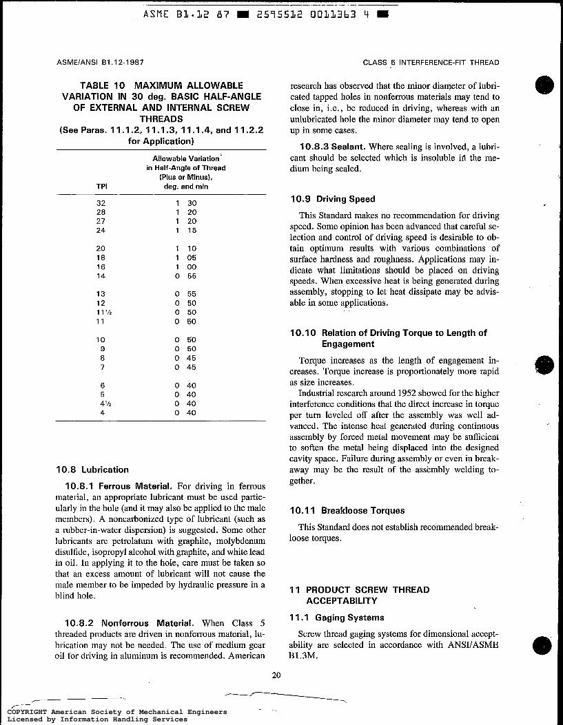
ASMElANSl B1.12-1987
TABLE 10 MAXIMUM ALLOWABLE VARIATION IN 30 deg. BASIC HALF-ANGLE OF EXTERNAL AND INTERNAL SCREW
THREADS (See Paras. 11.1.2, 11.1.3, 11.1.4, and 11.2.2
for Application)
Allowable Variation in Half-Angle of Thread
(Plus or Minus), TPI deg. and min
32 28 27 24
20 18 16 14
13 12 1 1’12 11
10 9 8 7
6 5 4’12 4
1 30 1 20 1 20 1 15
1 10 1 05 1 00 0 55
0 55 0 50 0 50 0 50
0 50 0 50 0 45 0 45
0 40 0 40 0 40 0 40
10.8 Lubrication
10.8.1 Ferrous Material. For driving in ferrous material, an appropriate lubricant must be used partic- ularly in the hole (and it may also be applied to the male members). A noncarbonized type of lubricant (such as a rubber-in-water dispersion) is suggested. Some other lubricants are petrolatum with graphite, molybdenum disulfide, isopropyl alcohol with graphite, and white lead in oil. In applying it to the hole, care must be taken so that an excess amount of lubricant will not cause the male member to be impeded by hydraulic pressure in a blind hole.
10.8.2 Nonferrous Material. When Class 5 threaded products are driven in nonferrous material, lu- brication may not be needed. The use of medium gear oil for driving in aluminum is recommended. American
20
CLASS 5 INTERFERENCE-FIT THREAD
research has observed that the minor diameter of lubri- cated tapped holes in nonferrous materials may tend to close in, i.e., be reduced in driving, whereas with an unlubricated hole the minor diameter may tend to open up in some cases.
10.8.3 Sealant. Where sealing is involved, a lubri- cant should be selected which is insoluble id the me- dium being sealed.
10.9 Driving Speed
This Standard makes no recommendation for driving speed. Some opinion has been advanced that careful se- lection and control of driving speed is desirable to ob- tain optimum results with various combinations of surface hardness and roughness. Applications may in- dicate what limitations should be placed on driving speeds. When excessive heat is being generated during assembly, stopping to let heat dissipate may be advis- able in some applications.
IO. 10 Relation of Driving Torque to Length of Engagement
Torque increases as the length of engagement in- creases. Torque increase is proportionately more rapid as size increases.
Industrial research around 1952 showed for the higher interference conditions that the direct increase in torque per turn leveled off after the assembly was well ad- vanced. The intense heat generated during continuous assembly by forced metal movement may be sufficient to soften the metal being displaced into the designed cavity space. Failure during assembly or even in break- away may be the result of the assembly welding to- gether.
10.1 1 Breakloose Torques
This Standard does not establish recommended break- loose torques.
1 1 PRODUCT SCREW THREAD ACCEPTABILITY
1 1.1 Gaging Systems
Screw thread gaging systems for dimensional accept- ability are selected in accordance with ANSUASME B1.3M.
COPYRIGHT American Society of Mechanical EngineersLicensed by Information Handling ServicesCOPYRIGHT American Society of Mechanical EngineersLicensed by Information Handling Services

CLASS 5 INTERFERENCE-FIT THREAD ASME/ANSI 61.1 2-1987
The design concept for interference-fit thread assem- blies does not lend itself to control of functional diam- eter size only.
11.1.1 System 21. When System 21 of ANSI/ ASME B1.3M is selected, product thread lead (includ- ing helix), flank angle variations, and circular runout are not considered. Where there is assembly and per- formance concern for uniform thickness of interference metal, cavity space, prevailing torque, and uniform stress, System 21 alone may not be acceptable, since it does not provide for minimum-material size control.
11.1.2 System 22. When System 22 of ANSI/ ASME B1.3M is selected, pitch diameter or thread- groove diameter inspection is required, and the product thread lead (including helix) and flank angles shall be considered acceptable when the minimum-material size (pitch diameter or thread-groove diameter in ANSV ASME B1.3M) and the maximum-material size (GO in ANWASME B1.3M) are accepted by the gages speci- fied for System 22, over the standard GO thread gage length.
11.1.3 System 23. When System 23 of ANSI/ ASME B1.3M is selected, pitch diameter or thread- groove diameter inspection is required, and the product thread lead (including helix) and flank angles shall be considered acceptable if they are within the allowable variations, specified in Tables 9 and 10, respectively. Also, the minimum-material size (pitch diameter or thread-groove diameter in ANWASME B1.3M) and maximum-material size (GO in ANWASME B1.3M) must be accepted by the gages specified for System 23, over the sfandard GO thread gage length.
Allowable variations in lead and flank angles are maximum values. Maximum variation in each of these and pitch diameter tolerance cannot be taken simulta- neously. (See paras. 10.4.2 and 11.2.2.)
1 1 .I .4 Modified System. When individual inspec- tions of lead (including helix) and flank angle variations are required, in addition to System 21 or 22 of ANSI/ ASME B1.3M, the allowable variations for these char- acteristics shall be specified.
11.2 Product Thread Characteristics Conformance Requirements Over Length of Engagement for Gaging Systems 22 and 23
1 1.2.1 Diameter Size-Pitch Diameter, Func- tional Diameter Size, Major Diameter, Minor Diameter. Functional diameter size measurement ver- ifies the maximum-material size over the gaging length. Pitch diameter size measurements at positions along and around the product thread Gerify the minimum-material size. Taper and roundness are included in the pitch di- ameter size measurements; therefore, they may not ex- ceed the pitch diameter size limits. (See para. 10.3.2.) Major diameter and minor diameter size verifies the cav- ity space. Table 11 gives limits of size for working gages and Table 12 gives limits of size for setting gages. Table 5 lists constants used in preparing gage dimension.
11.2.2 Form-Lead, Flank Angle, Root Profile, Crest Profile. When specified by fhe gaging system, lead and Hank angles are measured directly or as pitch diameter equivalents. Cumulative form restrictions in para. 10.4.2 apply. Root and crest profile are verified by optical projection or a mechanical/electrical tracer when specified.
11.2.3 Position of Axes When Assembled. The independent measurements of the various screw-thread characteristics do not ensure the required coaxial rela- tionship of the internal and external threads at assembly. When circular runout inspection is specified, refer to para. 10.6 for tolerances.
12 TORQUE
The maximum and minimum torque values were es- tablished by the National Screw Thread Commission in 1925 from data submitted from many companies. They plotted the volume of interference material per turn against the tangential force at the thread surface and de- veloped a parabolic equation.
F2 = 9 x 10' V for maximum torque
where V = volume of interference material per turn, in.3 F = tangential forces per turn at thread surface, lb
COPYRIGHT American Society of Mechanical EngineersLicensed by Information Handling ServicesCOPYRIGHT American Society of Mechanical EngineersLicensed by Information Handling Services
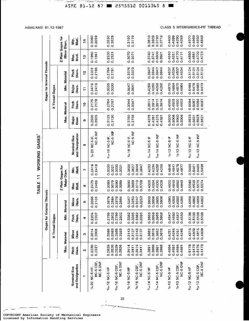
D
cn .
m D z L!?
TAB
LE 1
1
WO
RK
ING
GA
GE
S'
Gag
es fo
r E
xter
nal T
hrea
ds
Gag
es fo
r In
tern
al T
hrea
ds
X T
hrea
d G
ages
X
Thr
ead
Gag
es,
2 P
lain
Gag
es fo
r M
inor
Dia
m.
2 P
lain
Gag
es fo
r M
ajor
Dia
m.
Max
. M
ater
ial
Min
. Mat
eria
l M
ax. M
ater
ial
Min
. M
ater
ial
Pitc
h D
iam
. M
inor
D
iam
. P
itch
Dia
m.
Min
. M
atl:
M
ajor
D
iam
. M
ajor
D
iam
. P
itch
Dia
m.
Max
. M
atl.
Min
. M
atl.
N
omin
al S
ize
and
Des
igna
tion
Nom
inal
Siz
e an
d D
esig
natio
n P
itch
Dia
m.
10
0.21
75
0.21
78
0.27
64
0.27
67
0.33
44
0.33
47
0.39
1 1
0.39
1 4
0.39
1 1
0.39
14
0.45
00
0.45
03
0.45
00
0.45
03
0.50
84
0.50
87
0.50
84
0.50
87
Min
or
Dia
m.
Max
. M
atl.
2 4
5 6
7 8
9 1
1
12
1
'14-2
0 N
C-5
HF,
N
C-5
CSF
, N
C-5
ON
F
'/IS
-I
8 N
C-5
HF
5hs-
l 8 N
C-5
CSF
, N
C-5
ON
F
%-I
6 N
C-5
HF
%-I
6 N
C-5
CSF
, N
C-5
ON
F
'lis-1
4 N
C-5
HF
'116-
14
NC
-5 C
SF,
NC
-5 O
NF
'h-I
3 N
C-5
HF
%-I
3 N
C-5
CSF
, N
C-5
ON
F
9/1
s-l
2 N
C-5
HF
9hs-
l 2 N
C-5
CSF
, N
C-5
ON
F
13
0.1
960
0.19
61
0.25
20
0.25
21
0.30
70
0.30
71
0.37
40
0.37
41
0.36
00
0.36
01
0.43
10
0.43
1 1
0.41
70
0.
41 7
1
0.48
80
0.48
81
0.47
20
0.47
21
3
0.20
14
0.20
09
0.25
88
0.25
83
0.25
88
0.25
83
0.31
43
0.31
37
0.31
43
0.31
37
0.36
82
0.36
76
0.36
82
0.36
76
0.42
51
0.42
45
0.42
51
0.42
45
0.48
1 5
0.48
09
0.48
1 5
0.48
09
14
0.20
60
0.20
59
0.26
30
0.26
29
0.31
80
0.31
79
0.38
10
0.38
09
0.37
20
0.37
1 9
0.44
00
0.43
99
0.42
90
0.42
89
0.4
97
0,
0.49
69
0.48
50
0.48
49
0.22
30
0.22
27
0.28
29
0.28
26
0.28
29
0.28
26
0.34
14
0.34
1 1
0.34
14
0.34
1 1
0.39
91
0.39
88
0.39
91
0.39
88
0.45
84
0.45
81
0.45
84
0.45
81
0.51
76
0.51
73
0.51
76
0.51
73
0.22
04
0.22
07
0.27
99
0.28
02
0.27
99
0.28
02
0.33
82
0.33
85
0.33
82
0.33
85
0.39
55
0.39
58
0.39
55
0.39
58
0.45
47
0.45
50
0.45
47
0.45
50
0.51
36
0.51
39
0.51
36
0.51
39
0.20
96
0.21
01
0.26
79
0.26
84
0.26
79
0.26
84
0.32
47
0.32
53
0.32
47
0.32
53
0.38
00
0.38
06
0.38
00
0.38
06
0.43
80
0.43
86
0.43
80
0.43
86
0.49
56
0.49
62
0.49
56
0.49
62
0.24
70
0.24
69
0.30
80
0.30
79
0.30
90
0.30
89
0.36
90
0.36
89
0.37
1 0
0.
3709
0.43
05
0.43
04
0.43
30
0.43
29
0.49
20
0.49
19
0.49
50
0.49
49
0.55
40
0.55
39
0.55
75
0.55
74
0.24
1 8
0.24
19
0.30
20
0.30
21
0.30
30
0.30
31
0.36
26
0.36
27
0.36
46
0.36
47
0.42
33
0.42
34
0.42
58
0.42
59
0.48
46
0.48
47
0.48
76
0.48
77
0.54
60
0.54
61
0.54
95
0.54
96
'/e20
NC
-5 IF
, N
C-5
INF
0.25
00
0.25
05
0.31
25
0.31
30
0.37
50
0.37
56
0.43
75
0.43
81
0.43
75
0.43
81
0.50
00
0.50
06
0.50
00
0.50
06
0.56
25
0.56
31
0.56
25
0.56
31
0.24
1 8
0.24
1 3
0.30
35
0.30
30
0.36
47
0.36
41
0.42
56
0.42
50
0.42
56
0.42
50
0.48
70
0.48
64
0.48
70
0.48
64
0.54
85
0.54
79
0.54
85
0.54
79
0.22
01
0.21
98
0.27
94
0.27
91
0.33
76
0.33
73
0.39
47
0.39
44
0.39
47
0.39
44
0.45
37
0.45
34
0.45
37
0.45
34
0.51
24
0.51
21
0.51
24
0.51
21
'/is-1
8 N
C-5
IF,
NC
-5 IN
F
3/s-
l 6
NC
-5 IF
, N
C-5
INF
'/is-
14 N
C-5
IF
'116-
14
NC
-5 IN
F
'h-I
3 N
C-5
IF
%-I
3 N
C-5
INF
%6
-l2
NC
-5 IF
9/1s
-l 2
NC
-5 IN
F
COPYRIGHT American Society of Mechanical EngineersLicensed by Information Handling ServicesCOPYRIGHT American Society of Mechanical EngineersLicensed by Information Handling Services
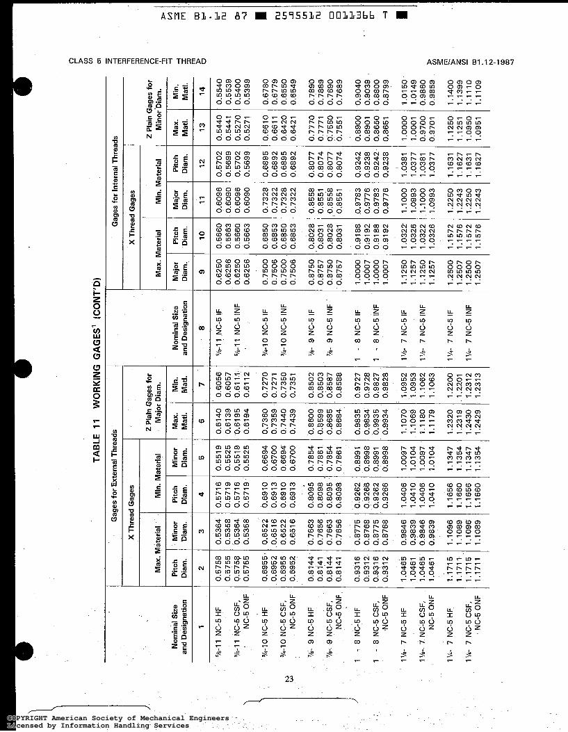
TAB
LE 1
1 W
OR
KIN
G G
AG
ES
' (C
ON
T'D
)
Gag
es fo
r E
xter
nal T
hrea
ds
Gag
es fo
r In
tern
al T
hrea
ds
X T
hrea
d G
ages
Y
Thre
ad G
ages
2 P
lain
Gag
es fo
r M
ajor
Dia
m.
2 P
lain
Gag
es fo
r M
inor
'Dia
m.
Max
. Mat
eria
l M
in.
Mat
eria
l M
ax.
Mat
eria
l M
in.
Mat
eria
l
Pitc
h D
iam
. M
inor
'D
iam
. P
itch
Dia
m.
Min
. M
atl.
Maj
or
Dia
rn.
Nom
inal
Siz
e an
d D
esig
natio
n
1
%-I
1 N
C-5
HF
5/s-
l 1 N
C-5
CSF
, N
C-5
ON
F
?'4-IO
NC
-5 H
F
Nom
inal
Siz
e an
d D
esig
natio
n M
inor
D
iam
. M
ax.
Mat
l. P
itch
Dia
rn.
Maj
or
Dia
m.
Pitc
h D
iam
. M
ax.
Mat
l.
13
Min
. M
atl.
14
6
7 8
10
11
12
2
0.57
58
0.57
55
0.57
58
0.57
55
0.69
55
0.69
52
0.69
55
0.69
52
0.81
44
0.81
41
0.81
44
0.81
41
0.93
1 6
0.93
1 2
0.93
1 6
0.93
1 2.
1.04
65
1.04
61
1.04
65
1.04
61
1.17
15
1.17
11
1.17
15
1.17
11
3
0.53
64
0.53
58
0.53
64
0.53
58
0.65
22
0.65
1 6
0.65
22
0.65
1 6
0.76
63
0.76
56
0.76
63
0.76
56
0.87
75
0.87
68
0.87
75
0.87
68
0.98
46
0.98
39
0.98
46
0.98
39
1.10
96
1.10
89
1.10
96
1.10
89
4
0.57
16
0.57
19
0.57
16
0.57
19
0.69
10
0.69
13
0.69
10
0.69
13
0.80
95
0.80
98
0.80
95
0,80
98
0.92
62
0.92
66
0.92
62
0.92
66
1.04
06
1.04
1 0
1.
0406
1.
041 0
1.16
56
1.16
60
1.16
56
1.16
60
5
0.55
19
0.55
25
0,55
19
0.55
25
0.66
94
0.67
00
0.66
94
0.67
00
0.78
54
0.78
61
0.78
54
0.78
61
0.89
91
0.89
98
0.89
91
0.89
98
1.00
97
1.01
04
1.
0097
1.
0104
1.13
47
1.13
54
1.13
47
1.13
54
9
0.62
50
0.62
56
0.62
50
0.62
56
0.75
00
0.75
06
0.75
00
0.75
06
0.87
50
0.87
57
0.87
50
0.87
57
1 .oo
oo
1.00
07
1 .oo
oo
1 .O
QO
7
1.12
50
1.12
57
1.12
50
1.12
57
1.25
00
1.25
07
1.25
00
1.25
07
0.61
40
0.61
39
9.61
95
0.61
94
0.73
60
0.73
59
0.74
40
0.74
39
0.86
00
0.85
99
0.86
85
0.86
84
0.c1
835
0.48
34
0.99
35
0.99
34
1.10
70
1.10
69
1.11
80
1.11
79
1.23
20
1.23
1 9
1 .24
30
1.24
29
0.60
56
0.60
57
0.61
11
0.61
12
0.72
70
0.72
71
0.73
50
0.73
51
0.85
02
0.85
03
0.85
87
0.85
88
0.97
27
0.97
28
0.98
27
0.98
28
1.09
52
1.09
53
1.10
62
1.10
63
1.22
00
1.22
01
1.23
1 2
1.23
1 3
%-I
1 N
C-5
IF
%-I
1 N
C-5
INF
3/4-'1
0 N
C-5
IF
V4
-IO
N
C-5
INF
7/ü-
9
NC
-5 IF
'/E-
9 N
C-5
INF
1 -
8 N
C-5
IF
1 -
8 N
C-5
1NF
11/ü-
7
NC
-5 IF
ll/ü
- 7
NC
-5 IN
F
1 '/4-
7
"2-5
IF
1%
7 N
C-5
INF
0.56
60
0.56
63
0.56
60
0.56
63
0.68
50
0.68
53
0.68
50
0.68
53
0.80
28
0.80
31
0.80
28
0.80
31
0.91
88
0.91
92
0.91
88
0.91
92
1.03
22
1.03
26
1.03
22
1.03
26
1 .I 5
72
1.15
76
1 .I 57
2 1.
1576
0.60
96
0.60
90
0.60
96
0.60
90
0.73
28
0.73
22
0.73
28
0.73
22
0.85
58
0.85
51
0.85
58
0.85
51
0.97
83
0.97
76
0.97
83
0.97
76
1.10
00
1.09
93
1.10
00
1.09
93
1.22
50
1.22
43
1.22
50
1.22
43
0.57
02
0.56
99
0.57
02
0.56
99
0.68
95
0.68
92
0.68
95
0.68
92
0.80
77
0.80
74
0.80
77
0.80
74
0.92
42
0.92
38
0.92
42
0.92
38
1.03
81
1.03
77
1.03
81
1.03
77
1.16
31
1.16
27
1.16
31
1.16
27
I
0.54
40
0.54
41
0.52
70
0.52
71
0.66
10
0.66
1 1
0.64
20
0.64
21
0.77
70
0.77
71
0.75
50
0.75
51
0.89
09
0.89
01
0.86
50
0.86
51
1 .oo
oo
1.00
01
0.97
00
0.97
01
1.12
50
1.12
51
1.09
50
1.09
51
0.55
40
0.55
39
0.54
00
0.53
99
0.67
80
0.67
79
0.65
50
0.65
49
0.78
90
0.78
89
0.76
90
0.76
89
0.90
40
0.90
39
0.88
00
0.87
99
1.01
50
1.01
49
0.98
60
0.98
59
1.14
00
1.13
99
1.11
10
1.11
09
h)
3/4-
10 N
C-5
CSF
, w
N
C-5
ON
F
'/ü-
9 N
C-5
HF
'/ü- 9
NC
-5 C
SF,
NC
-5 O
NF
1 -
8 N
C-5
HF
1 -
8 N
C-5
CSF
, N
C-5
ON
F
I'h
- 7
NC
-5 H
F
1'h-
7 N
C-5
CSF
, N
C-5
ON
F
1'h-
7 N
C-5
HF
1 '/4
- 7
NC
-5 C
SF,
NC
-5 O
NF
COPYRIGHT American Society of Mechanical EngineersLicensed by Information Handling ServicesCOPYRIGHT American Society of Mechanical EngineersLicensed by Information Handling Services
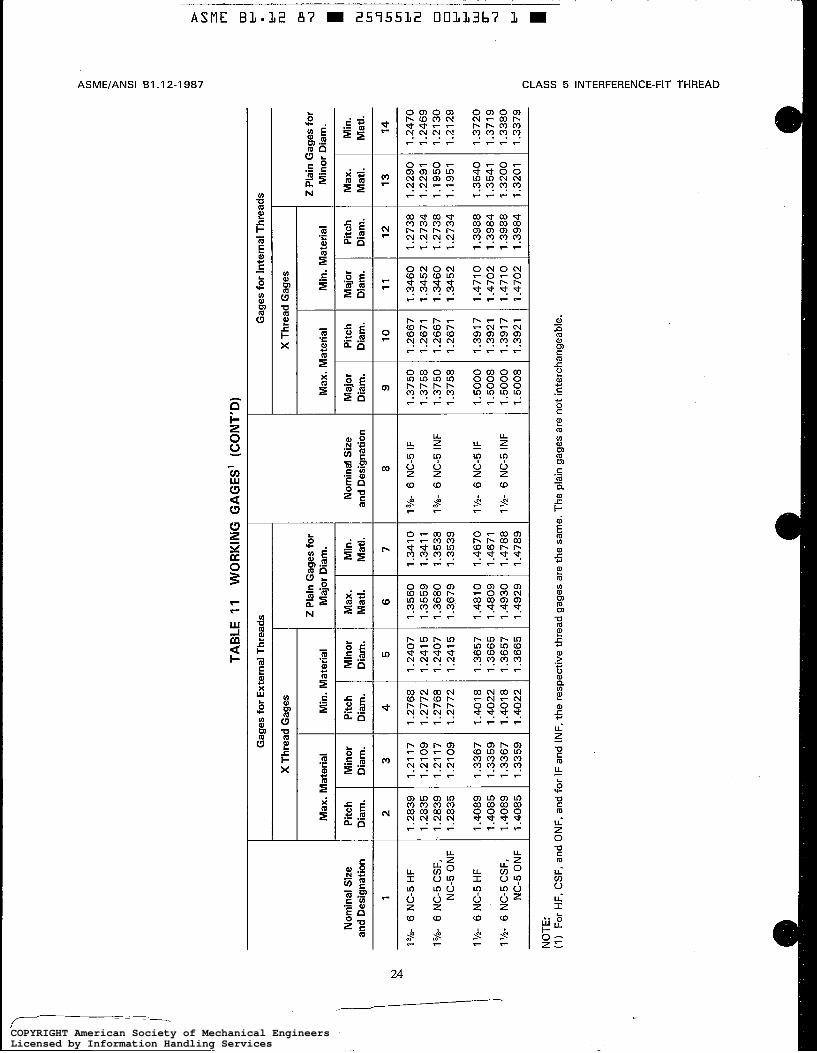
Maj
or
Dia
m.
11
1.34
60
1.34
52
1.34
60
1.34
52
1.47
10
1.47
02
1.47
10
1.47
02
Pitc
h D
iam
.
12
1.27
38
1.27
34
1.27
38
1.27
34
1.39
88
1.39
84
1.39
88
1.39
84
1.24
07
1.24
1 5
1.24
07
1.24
1 5
1.36
57
1.36
65
1.36
57
1.36
65
1.35
60
1.35
59
1.36
80
1.36
79
1.48
1 0
1.48
09
1.49
30
1.49
29
I3h-
6 N
C-5
HF
1%-
6 N
C-5
CSF
, N
C-5
ON
F
1%-
6 N
C-5
HF
l’h-
6 N
C-5
CSF
, N
C-5
ON
F
1.28
39
1.28
35
1.28
39
1.28
35
1.40
89
1.40
85
1.40
89
1.40
85
TAB
LE 1
1 W
OR
KIN
G G
AG
ES
’ (C
ON
T’D
)
Gag
es fo
r In
tern
al T
hrea
ds
Gag
es fo
r E
xter
nal T
hrea
ds
X T
hrea
d G
ages
X
Thr
ead
Gag
es
2 P
lain
Gag
es fo
r M
inor
Dia
m.
Mat
l. M
atl.
2 P
lain
Gag
es fo
r M
in.
Mat
eria
l M
ajor
Dia
m.
Max
. M
ater
ial
Max
. M
ater
ial
Dia
m.
Mat
l.
-‘F
Min
or
Dia
m.
Nom
inai
Siz
e an
d D
esig
natio
n
8
Pitc
h D
iam
.
10
Nom
inal
Siz
e P
itch
Ep
Pitc
h D
iam
.
4
Min
. M
atl.
7
Maj
or
Dia
m.
9
3
1.21
17
1.21
09
1.21
17
1.21
09
1.33
67
1.33
59
1.33
67
1.33
59
1.27
68
1.27
72
1.27
68
1.27
72
1.40
1 8
1.40
22
1.40
1 8
1.40
22
1.34
1 0
1.
341
1 1.
3538
1.
3539
1.46
70
1.46
7 1
1.47
88
1.47
89
1%
6 N
C-5
IF
I3h-
6 N
C-5
INF
1.37
50
1.37
58
1.37
50
1.37
58
1.50
00
1 -5
00
8
1 .5
000
1.50
08
1.26
67
1.26
71
1.26
67
1.26
71
1.39
1 7
1.39
21
1.39
17
1.39
21
1%
- 6
NC
-5 IF
I’h-
6 N
C-5
INF
P $ 5 cn
(J1 -
NO
TE:
(1)
For H
F, C
SF, a
nd O
NF,
and
for
IF a
nd IN
F, t
he r
espe
ctiv
e th
read
gag
es a
re th
e sa
me.
The
pla
in g
ages
are
not
inte
rcha
ngea
ble.
m 3
-n
rn 3
rn z m n -I -I I
3
U
COPYRIGHT American Society of Mechanical EngineersLicensed by Information Handling ServicesCOPYRIGHT American Society of Mechanical EngineersLicensed by Information Handling Services
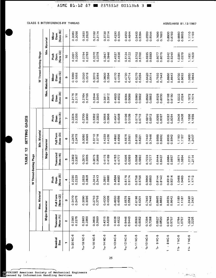
TAB
LE 1
2
SE
TTIN
G G
AG
ES
W T
hrea
d-S
ettin
g P
lugs
Max
. Mat
eria
l M
in.
Mat
eria
l W
Thr
ead-
Set
ting
Rin
gs
Maj
or D
iam
eter
M
ajor
Dia
met
er
Max
. Mat
eria
l M
in. M
ater
ial
Pitc
h D
iam
. [N
ote
i3i1
Min
or
Dia
m.
[No
te i5
i1
Pitc
h D
iam
. [N
ote
i3ii
Min
or
Dia
m.
[No
te 16
11
Pitc
h D
iam
. [N
ote
(3ii
Pitc
h D
iam
. [N
ote
(3ii
4
Nom
inal
S
ize
Trun
cate
d [N
ote
i4ii
Full
Form
[N
ote
(211
Tr
unca
ted
[No
te i1
)i
2
Full
Form
[N
ote
(211
3
1 5
6
0.24
70
0.24
75
0.30
90
0.30
95
0.37
10
0.37
16
0.43
30
0.43
36
0.49
50
0.49
56
0.55
75
0.55
81
0.61
95
0.62
01
0.74
40
0.74
46
0.86
85
0.86
92
0.99
35
0.99
42
1.11
80
1.11
87
1.24
30
1.24
37
7
0.22
04
0.22
05
0.27
00
0.28
00
0.33
82
0.33
83
0.39
55
0.39
56
0.45
47
0.45
48
0.51
36
0.51
38
0.57
16
0.57
18
0.69
10
0.69
12
0.80
95
0.80
97
0.92
62
0.92
64
1.04
06
1.04
08
1.16
56
1.16
58
8
0.21
75
0.21
76
0.27
64
0.27
65
0.33
44
0.33
45
0.39
1 1
0.39
12
0.45
00
0.45
02
0.50
84
0.50
86
0.56
60
0.56
62
0.68
50
0.68
52
0.80
28
0.80
30
0.91
88
0.91
90
1.03
22
1.03
24
1.15
72
1.15
74
9
0.19
60
0.19
55
0.25
20
0.25
1 5
0.30
70
0.30
64
0.36
00
0.35
94
0.41
70
0.41
64
0.47
20
0.47
14
0.52
70
0.52
64
0.64
20
0.64
14
0.75
50
0.75
43
0.86
50
0.86
43
0.97
00
0.96
93
1.09
50
1.09
43
10
0.22
01
0.22
00
0.27
94
0.27
93
0.33
76
0.33
75
0.39
47
0.39
46
0.45
37
0.45
36
0.51
24
0.51
22
0.57
02
0.57
00
0.68
95
0.68
93
0.80
77
0.80
75
0.92
42
0.92
40
1.03
81
1.03
79
1.16
31
1.16
29
11
0.20
60
0.20
55
0.26
30
0.26
25
0.31
80
0.31
74
0.37
20
0.37
14
0.42
90
0.42
84
0.48
50
0.48
44
0.54
00
0.53
94
0.65
50
0.65
44
0.76
90
0.76
83
0.88
00
0.87
93
0.98
60
0.98
53
1.11
10
1 .I 1
03
-I W I
m
U
L-
L- m
m 4 I m
Ln 5
Ln
Ln
I+ Ill
0
0
t-l
L-
W
0-
rn
W I
'h-2
0 N
C-5
'AS-
18 N
C-5
3/a-
l 6 N
C-5
%6-
14 N
C-5
VI %
-I 3
NC
-5
9~6-
1 2 N
C-5
't's-1
1 N
C-5
3/4-
1 0 N
C-5
7/~
- 9 N
C-5
1 -
8 N
C-5
I'/&
7 N
C-5
1'/4
- 7
NC
-5
0.23
80
0.23
75
0.29
93
0.29
88
0.36
05
0.35
99
0.42
1 5
0.42
09
0.48
28
0.48
22
0.54
46
0.54
40
0.60
58
0.60
52
0.72
94
0,72
88
0.85
27
0.85
20
0.97
64
0.97
57
1.07
64
1.07
57
1.22
42
1.22
35
0.24
70
0.24
75
0,30
90
0.30
95
0.37
1 0
0.37
1 6
0.43
30
0.43
36
(0.4
950
9.49
56
0.55
75
0.55
81
0.61
95
0.62
01
0.74
40
0.74
46
0.86
85
0,86
92
0.99
35
0.99
42
1.11
80
1.11
87
1.24
30
1.24
37
0.22
30
0.22
29
0.28
29
0.28
28
0.34
1 4
0.34
1 3
0.39
91
0.39
90
0.45
84
0.45
82
0.51
76
0.51
74
0.57
58
0.57
56
0.69
55
0.69
53
0.81
44
0.81
42
0.93
1 6
0.93
14
1.04
65
1.04
63
1.17
15
1.17
13
0.23
62
0.23
57
0.29
70
0.29
65
0.35
75
0.35
69
0.41
75
0.41
69
0.47
83
0.47
77
0.53
95
0.53
89
0.59
98
0.59
92
0.72
23
0.72
1 7
0.84
44
0.84
37
0.96
64
0.96
57
1.08
71
1.08
54
1.21
21
1.21
14
COPYRIGHT American Society of Mechanical EngineersLicensed by Information Handling ServicesCOPYRIGHT American Society of Mechanical EngineersLicensed by Information Handling Services
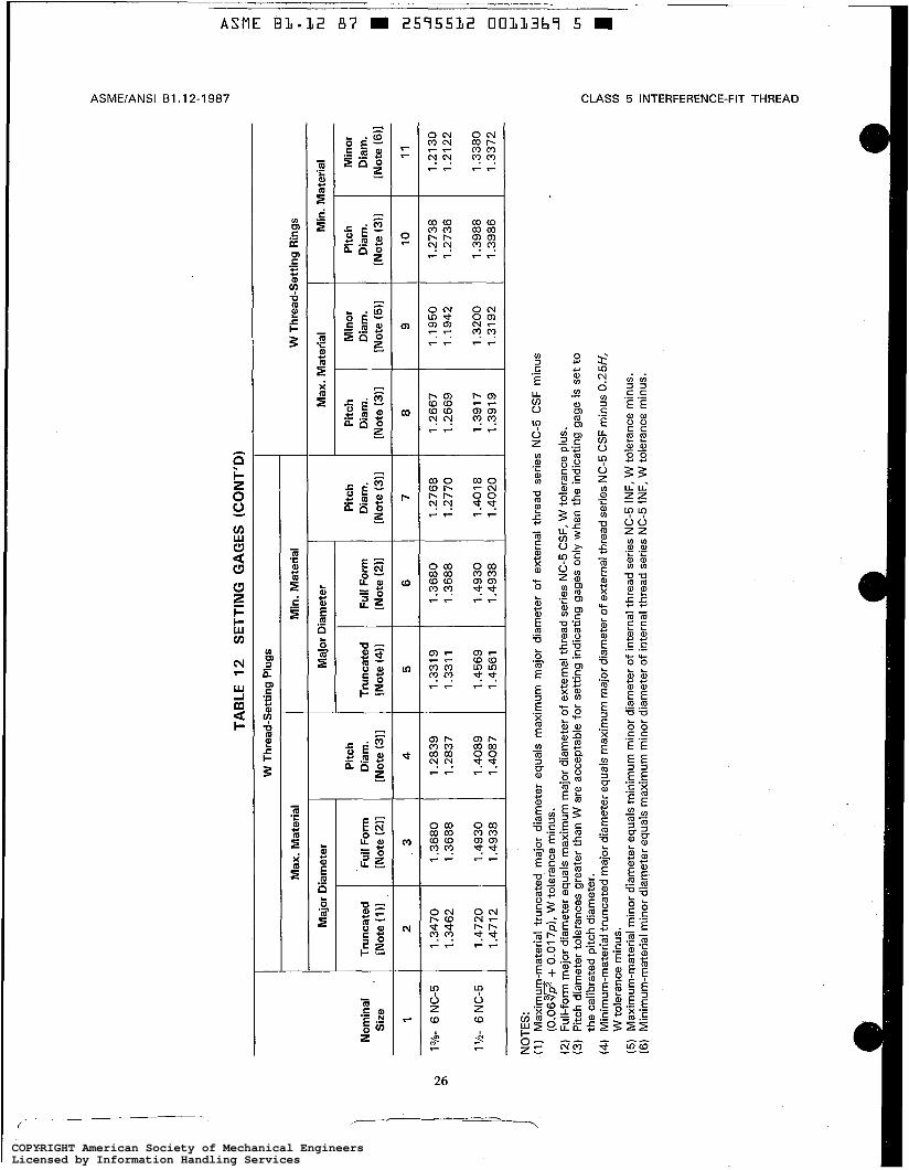
TAB
LE 1
2
SE
TTIN
G G
AG
ES
(C
ON
T'D
)
W T
hrea
d-S
ettin
g P
lugs
Nom
inal
S
ize
1
h>
I3h- 6
NC
-5
Q\
1%-
6 N
C-5
Max
. Mat
eria
l M
in.
Mat
eria
l W
Thr
ead-
Set
ting
Rin
gs
Maj
or D
iam
eter
M
ajor
Dia
met
er
Max
. M
ater
ial
Min
. M
ater
ial
Pitc
h P
itch
Pitc
h M
inor
P
itch
Min
or
Tru
ncat
ed
Ful
l For
m
Dia
m.
Tru
ncat
ed
Ful
l For
m
Dia
m.
Dia
m.
Dia
m.
Dia
m.
Dia
m.
[Not
e (I
)]
[Not
e (2
11
[Not
e (3
)]
[Not
e (4
11
[Not
e (2
11
[Not
e (3
)1
[Not
e (3
)1
[Not
e (5
11
[Not
e (3
11
[Not
e (611
2
3 4
5
6
7
8
9 10
1
1
1.34
62
1.36
88
1.28
37
1.33
1 1
1.36
88
1.27
70
1.26
69
1.19
42
1.27
36
1.21
22
1.21
30
1.27
38
1.34
70
1.36
80
1.28
39
1.33
1 9
1.36
80
1.27
68
1.26
67
1.19
50
1.47
20
1.49
30
1.40
89
1.45
69
1.49
30
1.40
1 8
1.39
17
1.32
00
1.39
88
1.33
80
1.47
12
1.49
38
1.40
87
1.45
61
1.49
38
1.40
20
1.39
19
1.31
92
1.39
86
1.33
72
NO
TES
: (1
) M
axim
um-m
ater
ial t
runc
ated
maj
or d
iam
eter
equ
als
max
imum
maj
or d
iam
eter
of
exte
rnal
thr
ead
serie
s N
C-5
CS
F m
inus
(0
.06
G +
0.0
17
~).
W to
lera
nce
min
us.
(2)
Ful
l-for
m m
ajor
dia
met
er e
qual
s m
axim
um m
ajor
dia
met
er o
f ex
tern
al th
read
ser
ies
NC
-5 C
SF,
W to
lera
nce
plus
. (3
) P
itch
diam
eter
tole
ranc
es g
reat
er th
an W
are
acc
epta
ble
for
setti
ng in
dica
ting
gage
s on
ly w
hen
the
indi
catin
g ga
ge is
set
to
th
e ca
libra
ted
pitc
h di
amet
er.
(4)
Min
imum
-mat
eria
l trun
cate
d m
ajor
dia
met
er e
qual
s m
axim
um m
ajor
dia
met
er o
f ext
erna
l thr
ead
serie
s N
C-5
CS
F m
inus
0.2
5H,
W to
lera
nce
min
us.
(5)
Max
imum
-mat
eria
l min
or d
iam
eter
equ
als
min
imum
min
or d
iam
eter
of i
nter
nal t
hrea
d se
ries
NC
-5 IN
F, W
tole
ranc
e m
inus
. (6
) M
inim
um-m
ater
ial m
inor
dia
met
er e
qual
s m
axim
um m
inor
dia
met
er o
f in
tern
al th
read
ser
ies
NC
-5 IN
F, W
tole
ranc
e m
inus
.
v) 3
m
m
t-l
t-'
Tu
CP
4 I
Tu
Ln
Jl
(n
Ln
t-l N
0
0
t-'
t-'
W
0- d
in
cn
cn F
I
ai
COPYRIGHT American Society of Mechanical EngineersLicensed by Information Handling ServicesCOPYRIGHT American Society of Mechanical EngineersLicensed by Information Handling Services
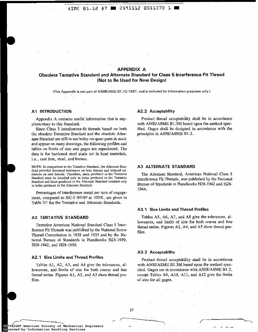
ASME B 1 * 1 2 87 2575512 0011370 1 W
APPENDIX A Obsolete Tentative Standard and Alternate Standard for Class 5 Interference-Fit Thread
(Not to Be Used for New Design)
(This Appendix is not part of ASME/ANSI B I .I 2-1 987, and is incIuded for information purposes only.)
A I INTRODUCTION
Appendix A contains useful information that is sup- plementary to this Standard.
Since Class 5 interference-fit threads based on both the obsolete Tentative Standard and the obsolete Alter- nate Standard are still in use today on spare parts in stock and appear on many drawings, the following profiles and tables on limits of size and gages are reproduced. The data is for hardened steel studs set in hard materials, i.e., cast iron, steel, and bronze.
NOTE: In comparison to the Tentative Standard, the Alternate Stan- dard provided increased tolerances on hole threads and reduced tol- erances on stud threads. Therefore, studs produced to the Tentative Standard must be installed only in holes produced fo the Tentative Standard and those produced to the Alternate Standard installed only in holes produced to the Alternate Standard.
Percentages of interference metal per turn of engage- ment, compared to NC-5 HF/IF at loo%, are given in Table D1 for the Tentative and Alternate Standards.
A2 TENTATIVE STANDARD
Tentative American National Standard Class 5 Inter- ference Fit Threads was publihed by the National Screw Thread Commission in 1928 and 1933 and by the Na- tional Bureau of Standards in Handbooks H25-1939, H28-1942, and H28-1950.
A2.1 Size Limits and Thread Profiles
Tables A l , A2, A3, and A4 give the tolerances, al- lowances, and limits of size for both coarse and fine thread series. Figures Al , A2, and A3 show thread pro- files.
A2.2 Acceptability
Product thread acceptability shall be in accordance with ANSUASME B1.3M based upon the method spec- ified. Gages shall be designed in accordance with the principles in ANSUASME B1.2.
A3 ALTERNATE STAND RD
The Alternate Standard, American National Class 5 Interference Fit Threads, was published by the National Bureau of Standards in Handbooks H28-1942 and H28- 1944.
A3.1 Size Limits and Thread Profiles
Tables A5, A6, A7, and A8 give the tolerances, al- lowances, and limits of size for both coarse and fine thread series. Figures A i , A4, and A5 show thread pro- files.
A3.2 Acceptability
Product thread acceptability shall be in accordance with ANSIIASME B1.3M based upon the method spec- ified. Gages are in accordance with ANWASME B1.2, except Tables A9, A10, All , and A12 give the limits of size for all gages.
27
-.. .- COPYRIGHT American Society of Mechanical EngineersLicensed by Information Handling ServicesCOPYRIGHT American Society of Mechanical EngineersLicensed by Information Handling Services

A S M E B 3 . 3 2 87 = 2575532 0033373 3
TENTATIVE STANDARD AND ALTERNATE STANDARD
Classification and Tolerances
GENERAL NOTE: Heavy line shows basic size.
FIG. A I ILLUSTRATION OF TOLERANCES, ALLOWANCES, AND CREST CLEARANCES FOR TENTATIVE AND ALTERNATE CLASS 5 FIT FOR THREADED STUDS
28
COPYRIGHT American Society of Mechanical EngineersLicensed by Information Handling ServicesCOPYRIGHT American Society of Mechanical EngineersLicensed by Information Handling Services
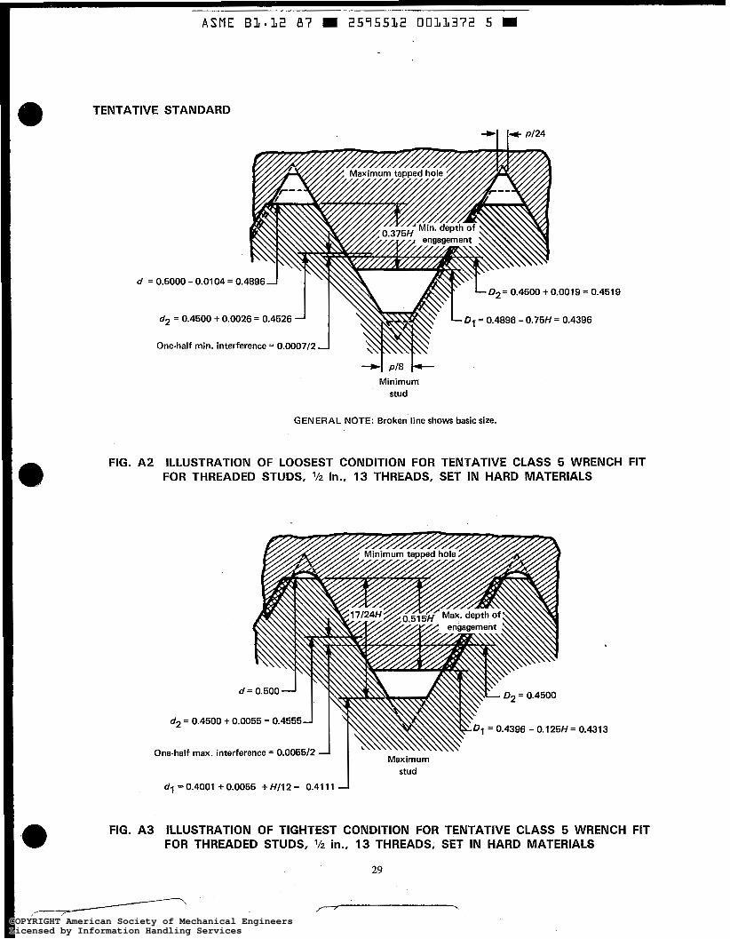
ASME B l . 3 2 8 7 = 2595532 0 0 3 3 3 7 2 5
TENTATIVE STANDARD
d = D2= 0.4500 + 0.0019 = 0.
D~ = 0.4896 - 0 . 7 5 ~ = 0.4396
Minimum stud
GENERAL NOTE: Broken line shows basic size.
,4519
FIG. A2 ILLUSTRATION OF LOOSEST CONDITION FOR TENTATIVE CLASS 5 WRENCH FIT FOR THREADED STUDS, Vz in., 13 THREADS, SET IN HARD MATERIALS a
'""R d = 0.500 1
d2 = 0.4500 + 0.0055 = 0.4555
One-half max. interference = 0.005512 Maximum I stud
dl = 0.4001 + 0.0055 + HI12 = 0.41 11 -1
i = 0.4313
FIG. A3 ILLUSTRATION OF TIGHTEST CONDITION FOR TENTATIVE CLASS 5 WRENCH FIT FOR THREADED STUDS, l/z in., 13 THREADS, SET IN HARD MATERIALS
29
,- / ' \ COPYRIGHT American Society of Mechanical EngineersLicensed by Information Handling ServicesCOPYRIGHT American Society of Mechanical EngineersLicensed by Information Handling Services
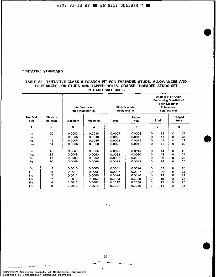
ASME B I - 1 2 87 2575522 0021373 7 W
TENTATIVE STANDARD
TABLE A I TENTATIVE CLASS 5 WRENCH FIT FOR THREADED STUDS, ALLOWANCES AND TOLERANCES FOR STUDS AND TAPPED HOLES, COARSE THREADED STUDS SET
IN HARD MATERIALS
Nominal Size
1
'14
318
'116
'11 6
112
518
314
'/l6
'16
1 1 '18
1 1/4 1 318
1 112
Threads per inch
2
20 18 16 14
13 12 11 10
9 8 7 7 6 6
Interference on Pitch Diameter, in.
Minim u m
3
0.0003 0.0005 0.0005 0.0006
0.0007 0.0008 0.0008 0.0009
0.0010 0.001 1 0.001 1 0.001 2 0.001 2 0.001 3
Maximum
4
0.001 8 0.0040 0.0045 0.0050
0.0055 0.0060 0.0060 0.0065
0.0065 0.0065 0.0065 0.0065 0.0065 0.0070
Pitch Diameter Tolerances, in.
Stud
5
0.0007 0.0020 0.0024 0.0026
0.0029 0.0032 0.0031 0.0033
0.0031 0.0027 0.0024 0.0023 0.001 7 0.0021
Tapped Hole
6
0.0008 0.001 5 0.001 6 0.001 8
0.0019 0.0020 0.0021 0.0023
0.0024 0.0027 0.0030 0.0030 0.0036 0.0036
Errors in Half-Angle Consuming One-Half of
Pitch Diameter Tolerances,
deg. and min
Stud
7
0 16 0 41 0 44 0 42
0 44 0 44 0 39 0 38
0 32 0 25 0 19 0 18 0 12 0 14
Tapped Hole
8
0 25 0 31 0 29 0 29
0 28 0 28 0 26 0 26
0 25 0 25 0 24 0 24 0 25 0 25
COPYRIGHT American Society of Mechanical EngineersLicensed by Information Handling ServicesCOPYRIGHT American Society of Mechanical EngineersLicensed by Information Handling Services

ASME B 1 * 1 2 87 2575532 0011374 7
TENTATIVE STANDARD
TABLE A2 TENTATIVE CLASS 5 WRENCH FIT FOR THREADED STUDS, ALLOWANCES AND TOLERANCES FOR STUDS AND TAPPED HOLES, FINE THREADED STUDS SET
IN HARD MATERIALS
Nominal Size
1
Threads per inch
2
28 24 24 20
20 18 18 16
14 14 12 12 12 12
interference on Pitch Diameter, in.
Minimum
3
0.0005 0.0005 0.0006 0.0006
0.0007 0.0007 0.0008 0.0008
0.0008 0.0009 0.0009 0.001 1 0.001 1 0.001 2
Maximum
4
0.0034 0.0037 0.0044 0.0044
0.0050 0.0050 0.0055 0.0059
0.0061 0.0069 0.0067 0.0060 0.0055 0.0050
Pitch Diameter Tolerances, in.
Stud
5
0.001 8 0.0020 0.0026 0.0025
0.0030 0.0028 0.0032 0.0035
0.0035 0.0042 0.0038 0.0029 0.0024 0.001 8
Tapped Hole
6
0.001 1 0.001 2 0.001 2 0.001 3
0.001 3 0.001 5 0.001 5 0.001 6
0.001 8 0.001 8 0.0020 0.0020 0.0020 0.0020
Errors in Haif-Angle Consuming One-Haif of
Pitch Diameter Tolerances,
deg. and min
Stud
7
0 58 0 55 1 11 0 57
1 9 0 58 1 6 1 4
0 56 1 7 0 52 0 40 0 33 0 25
Tapped Hole
8
0 35 0 33 0 33 0 30
0 30 0 31 0 31 0 29
0 29 0 29 0 28 0 28 0 28 0 28
COPYRIGHT American Society of Mechanical EngineersLicensed by Information Handling ServicesCOPYRIGHT American Society of Mechanical EngineersLicensed by Information Handling Services
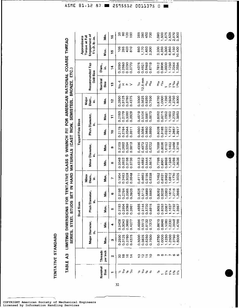
TEN
TATI
VE
STA
ND
AR
D
0.2049
0.2622
0.31 86
0.3736
0.431 3
0.4882
0.5444
0.6614
0.7768
0.8901
0.9998
1.1248
1.2286
1.3536
0.2103
0.2682
0.3254
0.3813
0.4396
0.4972
0.5542
0.6722
0.7888
0.9036
1.01 52
1.1402
1.2466
1.371 6
0.2500
0.31 25
0.3750
0.4375
0.5000
0.5625
0.6250
0.7500
0.8750.
1.1250
1.2500
1 .oo
oo
1.3750
1.5000
No.
4
0.2090
105
H
0.2660
265
P 0.3230
420
V
0.3770
610
850
'/IS
0.4375
12.5 rn
m
0.4921
1,170
%4
0.5469
1,450
43/64
0.6719
2,300
'%2
0.7812
3,200
1 1.0000
5,300
1%
1.1250
6,950
57/64
0.8906
4,250
1'%
4
1.2344
8,150
1 23/64
1.3594
10,400
TAB
LE A
3
LIM
ITIN
G D
IME
NS
ION
S F
OR
TE
NTA
TIV
E C
LAS
S 5
WR
EN
CH
FIT
FO
R A
ME
RIC
AN
NA
TIO
NA
L C
OA
RS
E T
HR
EA
D
SE
RIE
S,
STEE
L S
TUD
S S
ET
IN H
AR
D M
ATE
RIA
LS (
CA
ST
IRO
N,
SE
MIS
TEE
L, B
RO
NZE
, ET
C.1
I
I m
S
tud
Siz
es
Tapp
ed H
ole
Siz
es
Ap
pro
xim
ate
Maj
or
Torq
ue a
t Fu
ll R
ecom
men
ded
Tap
E
ngag
emen
t of
Dri
ll S
ize
1 V2
D, I
b-in
.
Min
or
Dia
m.,
in.
Max
.
7
Maj
or D
iam
eter
, in
. P
itch
Dia
met
er,
in.
Pitc
h D
iam
eter
, in
. M
inor
Dia
met
er,
in.
Min
. N
omin
al
Siz
e Th
read
s pe
r in
ch
2 20
18
16
14
13
12
11
10 9 8 7 7 6 6
Max
. M
in.
Min
. S
ize
Min
.
16
Min
.
10
Max
.
11
Max
.
5 1 '/4
VI B
w-
h)
'/l6
'A
518
314
7/8
1 1 '/0
1 '/4
1 3/0
1 1/2 '/l6
4
6 3
0.2500
0.31 25
0.3750
0.4375
0.5000
0.5625
0.6250
0.7500
0.8750
1 .oo
oo
1.1250
1.2500
1.3750
1.5000
0.2428
0.3043
0.3660
0.4277
0.4896
0.551 3
0.61 32
0.7372
0.8610
0.9848
1.1080
1.2330
1.3548
1.4798
0.21 86
0.2784
0.3365
0.3935
0.4526
0.51 12
0.5689
0.6882
0.8062
0.9226
1.0363
1.1614
1.2715
1.3966
0.1904
0.2483
0.3028
0.3549
0.41 11
0.4663
0.5195
0.6338
0.7452
0.8531
0.9562
1.0812
1.1770
1.3025
0.2175
0.2764
0.3344
0.391 1
0.4500
0.5084
0.5660
0.6850
0.8028
0.91 88
1.0322
1 .I 572
1.2667
1.391 7
0.21 83
0.2779
0.3360
0.3929
0.451 9
0.5104
0.5681
0.6873
0.8052
0.921 5
1.0352
1.1602
1.2703
1.3953
35
80
120
180
265
360
450
730
1,080
1,500
1,875
2,535
2,970
3,900
0.2193
0.2804
0.3389
0.3961
0.4555
0.5144
0.5720
0.691 5
0.8093
0.9253
1.0387
1 .I 637
1.2732
1.3987
COPYRIGHT American Society of Mechanical EngineersLicensed by Information Handling ServicesCOPYRIGHT American Society of Mechanical EngineersLicensed by Information Handling Services
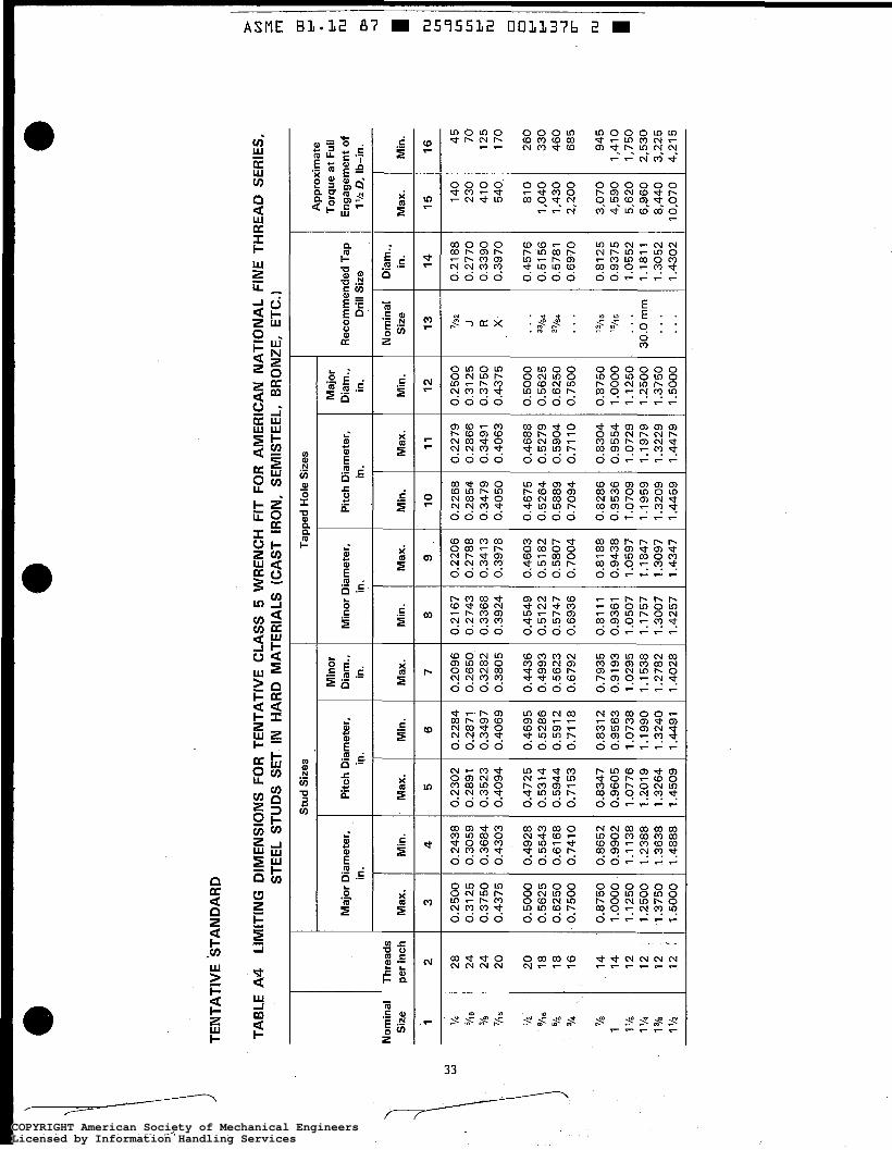
0.21 67
0.2743
0.3368
0.3924
0.4549
0.5122
0.5747
0.6936
0.81 1
1 0.9361
1.0507
1.1757
1.3007
1.4257
0.2206
0.2788
0.341 3
0.3978
0.4603
0.5182
0.5807
0.7004
0.8188
0.9438
1.0597
1.1847
1.3097
1.4347
0.2279
0.2866
0.3491
0.4063
0.4688
0.5279
0.5904
0.71 10
0.8304
0.9554
1.0729
1 .I 979
1.3229
1.4479
0.2500
0.31 25
0.3750
0.4375
0.5000
0.5625
0.6250
0.7500
0.8750
1 .OO
OO
1 .I 250
1.2500
1.3750
1.5000
0.2302
0.2891
0.3523
0.4094
0.4725
0.5314
0.5944
0.71 53
0.8347
0.9605
1.0776
1.2019
1.3264
1.4509
0.2284
0.2871
0.3497
0.4069
0.4695
0.5286
0.591 2
0.71 18
0.831 2
0.9563
1.0738
1.1990
1.3240
1.4491
TEN
TATI
VE
STA
ND
AR
D
P
cn 3
m
m
t-'
t-l m
m 4
1
m
fn
5
fn
Ln
I+
m 0
0
I+
t-'
W 4
0-
m 1
TAB
LE A
4 LI
MIT
ING
DIM
EN
SIO
NS
FO
R T
EN
TATI
VE
CLA
SS
5 W
RE
NC
H F
IT F
OR
AM
ER
ICA
N N
ATI
ON
AL
FIN
E T
HR
EA
D S
ERIE
S,
STEE
L S
TUD
S S
ET I
N H
AR
D M
ATE
RIA
LS (
CA
ST
IRO
N,
SE
MIS
TEE
L, B
RO
NZE
, E
TC.)
Stu
d S
izes
Ta
pped
Hol
e S
izes
A
pp
roxi
mat
e To
rque
at
Full
Eng
agem
ent
of
1 lh
D.
Ib-in
.
Min
or
Dia
m.,
in.
Maj
or
Maj
or
Dia
met
er,
in.
Pitc
h D
iam
eter
, in
. M
inor
Dia
met
er,
in.
Rec
omm
ende
d T
ap
Dri
ll S
ize
Nom
inal
S
ize
Thre
ads
per
inch
N
om
inal
S
ize
Dia
m.,
in.
14
Ma
x.
Min
. M
in.
10
0.2268
0.2854
0.3479
0.4050
0.4675
0.5264
0.5889
0.7094
0.8286
0.9536
1.0709
1.1959
1.3209
1.4459
-
Min
.
16
Max
.
3
Ma
x.
15
1
2 4
7 1
3
I
'/4
318
%6
'/I 6
112
9/16
518
3/4
,
718
1 1 118
1 '/4 1 3/8
1 v2
28
24
24
20
20
18
18
16
14
14
12
12
12
12
'
0.2438
0.3059
0.3684
0.4303
0.4928
0.5543
0.6168
0.7410
0.8652
0.9902
1.1138
1.2388
1.3638
1.4888
I 0.2096
0.2650
0.3282
0.3805
0.4436
0.4993
0.5623
0.6792
0.7935
0.91 93
1.0295
1.1538
1.2782
1.4028
'/32 J R X
...
37/e
4
... 6
%6
...
30.0 rn
m
...
0.21 88
0.2770
0.3390
0.3970
0.4576
0.51 56
0.5781
0.6970
0.81 25
0.9375
1.0552
1.1811
1.3052
1.4302
140
230
410
540
810
1,040
1,430
2,200
3,070
4,590
5,620
6,960
8,440
10,070
45
70
125
170
260
330
460
685
945
1,410
1,750
2,530
3,225
4,215
0.2500
0.31 25
0.3750
0.4375
0.5000
0.5625
0.6250
0.7500
0.8750
1 .oo
oo
1.1250
1.2500
1.3750
1 .5000
COPYRIGHT American Society of Mechanical EngineersLicensed by Information Handling ServicesCOPYRIGHT American Society of Mechanical EngineersLicensed by Information Handling Services
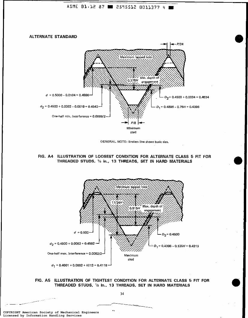
-- ASME 81.12 87 2595532 0031377 4
ALTERNATE STANDARD a
d = 0.5000 - 0.01
d2 = 0.4500 + 0.0062
One-half min.
D2= 0.4500 + 0.0034 = 0.
- 0.0019 = 0.4543 D1 = 0.4896 - 0.75H = 0.4396
interference = 0.0009/2
4534
Minimum stud
GENERAL NOTE: Broken line shows basic size.
FIG. A4 ILLUSTRATION OF LOOSEST CONDITION FOR ALTERNATE CLASS 5 FIT FOR THREADED STUDS, l/z in., 13 THREADS, SET IN HARD MATERIALS
d2 = 0.4500 + 0
One-half max. interference = 0.0062/2-1 Maximum J stud
dl = 0.4001 + 0.0062 + HI12 = 0.41 18
= 0.4313
FIG. A5 ILLUSTRATION OF TIGHTEST CONDITION FOR ALTERNATE CLASS 5 FIT FOR THREADED STUDS, in., 13 THREADS, SET IN HARD MATERIALS
34
/---
--\ w
I. COPYRIGHT American Society of Mechanical EngineersLicensed by Information Handling ServicesCOPYRIGHT American Society of Mechanical EngineersLicensed by Information Handling Services
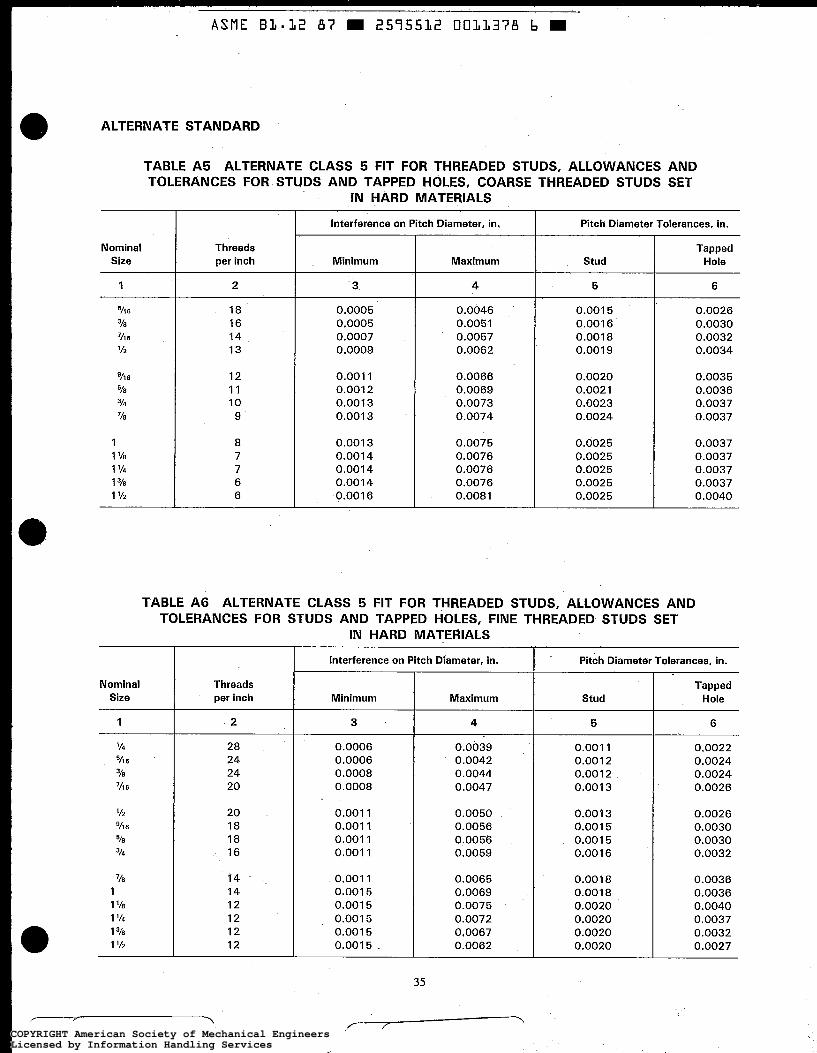
ALTERNATE STANDARD
TABLE A5 ALTERNATE CLASS 5 FIT FOR THREADED STUDS, ALLOWANCES AND TOLERANCES FOR STUDS AND TAPPED HOLES, COARSE THREADED STUDS SET
IN HARD MATERIALS
Pitch Diameter Tolerances, in. Interference on Pitch Diameter, in,
Tapped Hole
Nominal Size
Threads per inch Minimum Maximum Stud
5 1 2 3 4 6
6
Y E
Y2
Y 1 6
VE 3/4
7%
' h 6
1 1 '/E 1 '/4 1 1 '12
18 16 14 13
12 11 10 9
0.0005 0,0005 0.0007 0.0009
0.001 1 0.001 2 0.001 3 0.001 3
0.0046 0.0051 0.0057 0.0062
0.001 5 0.001 6 0.0018 0.001 9
0.0020 0.0021 0.0023 0.0024
0.0025 0.0025 0.0025 0.0025 0.0025
0.0026 0.0030 0.0032 0.0034
0.0035 0.0036 0.0037 0.0037
0.0037 0.0037 0.0037 0.0037 0.0040
0.0066 0.0069 0.0073 0.0074
0.001 3 0.001 4 0.0014 0.001 4 0.001 6
0.0075 0.0076 0.0076 0.0076 0.0081
TABLE A6 ALTERNATE CLASS 5 FIT FOR THREADED STUDS, ALLOWANCES AND TOLERANCES FOR STUDS AND TAPPED HOLES, FINE THREADED STUDS SET
IN HARD MATERIALS
Interference on Pitch Diameter, in. Pitch Diameter Tolerances, in.
Nominal Size
Threads per inch
Tapped Hole Maximum Stud Mini m u m
3
0.0006 0.0006 0.0008 0.0008
0.001 1 0.001 I 0.001 1 0.001 1
0.001 1 0.001 5 0.001 5 0.001 5 0.001 5 0.0015
1 2 4 5 6
0.0022 0.0024 0.0024 0.0026
28 24 24 20
20 18 18 16
T4 14 12 12 12 12
0.0039 0.0042 0.0044 0.0047
0.0050 0.0056 0.0056 0.0059
0.0065 0.0069 0.0075 0.0072 0.0067 0.0062
0.001 1 0.001 2 0.001 2 0.001 3
0.001 3 0.001 5 0.001 5 0.001 6
0.001 8 0.001 8 0.0020 0.0020 0.0020 0.0020
0.0026 0.0030 0.0030 0.0032
0.0036 0.0036 0.0040 0.0037 0.0032 0.0027
35
COPYRIGHT American Society of Mechanical EngineersLicensed by Information Handling ServicesCOPYRIGHT American Society of Mechanical EngineersLicensed by Information Handling Services

Min
.
6
0.2795
0.3379
0.3950
0.4543
0.5130
0.5708
0.6900
0.8078
0.9238
1.0373
1.1623
1.2718
1.3973
Max
.
7
0.2489
0.3034
0.3556
0.41 18
0.4669
0.5204
0.6346
0.7461
0.8541
0.9573
1.0823
1.1781
1.3036
9
0.2682
0.3254
0.3813
0.4396
0.4972
0.5542
0.6722
0.7888
0.9036
1.01 52
1.1402
1.2466
1.371 6
10
0.2764
0.3344
0.391 1
0.4500
0.5084
0.5660
0.6850
0.8028
0.9188
1.0322
1.1572
1.2667
1.391 7
265
420
610
850
1,170
1,450
2,300
3,200
4,250
5,300
6,950
8,150
10,400
80
120
195
295
425
560
880
1,230
1,630
2,120
2,780
3,210
4,340
ALT
ER
NA
TE S
TAN
DA
RD
TAB
LE A
7
LIM
ITIN
G D
IME
NS
ION
S F
OR
ALT
ER
NA
TE C
LAS
S 5
FIT
, A
ME
RIC
AN
NA
TIO
NA
L C
OA
RS
E T
HR
EA
D S
ER
IES
. S
TEE
L S
TUD
S S
ET
IN H
AR
D M
ATE
RIA
LS (
CA
ST
IRO
N,
SE
MIS
TEE
L,
BR
ON
ZE,
ETC
.)
Ap
pro
xim
ate
To
rqu
e a
t Ful
l E
ngag
emen
t of
1%
D. I
b-in
.
Stu
d S
izes
Ta
pped
Ho
le S
izes
Maj
or
Dia
m.,
in.
Min
or
in.
Maj
or
Dia
met
er,
in.
Rec
omm
ende
d Ta
p D
rill
Siz
e, i
n.
in. M
Ilj
~
Max
. N
om
inal
S
ize
No
min
al
Siz
e Th
read
s pe
r in
ch
Max
. M
in.
Max
. M
in.
Dia
m.
Min
. I
1 2
3
4
5 8
11
12
13
14
'/7 6
'h6
'/2 9h 6
5/6
3/4
'10
1 1 '/E 1 '14
1 1 '/
2
18
16
14
13
12
11
10 9
8 7
7 6 6
0.31 25
0.3750
0.4375
0.5000
0.5625
0.6250
0.7500
0.8750
1 .oo
oo
1.1250
1.2500
1.3750
I. 5000
0.3043
0.3660
0.4277
0.4896
0.5513
0.6132
0.7372
0.8610
0.9848
1.1080
1.2330
1.3548
1.4796
0.2810
0.3395
0.3968
0.4562
0.5150
0.5729
0.6923
0.8102
0.9263
1.0398
1.1648
1.2743
1.3998
0.2622
0.31 86
0.3736
0.431 3
0.4882
0.5444
0.6614
0.7768
0.8901
0.9998
1.1248
1.2286
1.3536
0.2790
0.3374
0.3943
0.4534
0.51 19
0.5696
0.6887
0.8065
0.9225
1.0359
1 .I 609
1.2704
1.3957
0.31 25
0.3750
0.4375
0.5000
0.5625
0.6250
0.7500
0.8750
1 .oo
oo
1.1250
1.2500
1.3750
1.5000
0.2656
0.3230
0.3750
0.4375
12.5 m
m
%4 ' '/3
2
"/64
1 1 '/E
1 ''/e4
1 23/64
0.2656
0.3230
0.3750
0.4375
0.4921
0.5469
0.671 9
0.781 2
0.8906
1 .oo
oo
1.1250
1.2344
1.3594
COPYRIGHT American Society of Mechanical EngineersLicensed by Information Handling ServicesCOPYRIGHT American Society of Mechanical EngineersLicensed by Information Handling Services
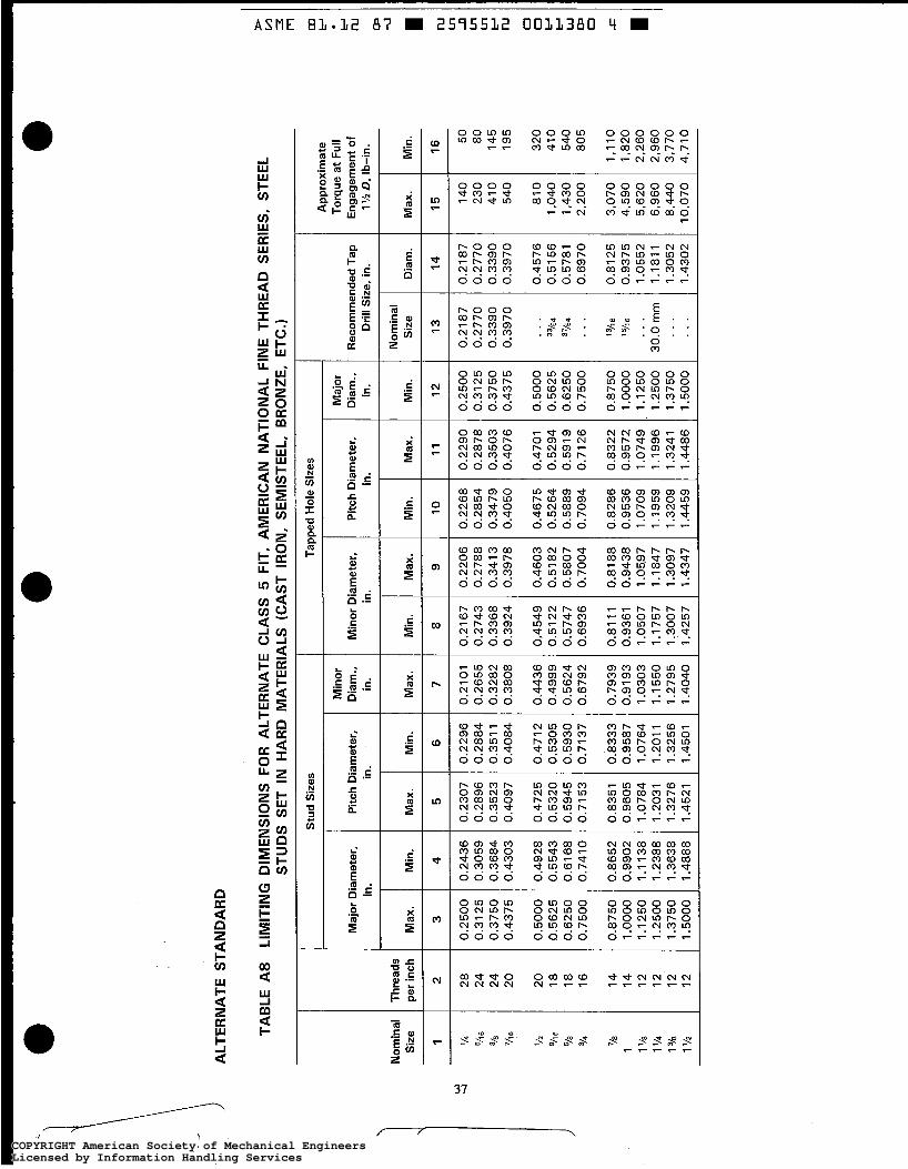
Min
.
8
0.21
67
0.27
43
0.33
68
0.39
24
0,45
49
0.51
22
0.57
47
0.69
36
0.81
11
0.
9361
1.
0507
1.
1757
1.
3007
1,
4257
Max
.
9
0.22
06
0.27
88
0.34
13
0.39
78
0.46
03
0.51
82
0.
5807
0.
7004
0.81
88
0.94
38
1.05
97
1.18
47
1.30
97
1.43
47
Nom
inal
S
ize
13
0.21
87
0.27
70
0.33
90
0.39
70
. . .
%4
37
/~4
. . .
‘%e
...
30
.0m
m
...
...
Dia
m.
14
0.21
87
0.27
70
0.33
90
0.39
70
0.45
76
0.51
56
0.57
81
0.69
70
0.81
25
0.93
75
1.05
52
1.18
11
1.30
52
1.43
02
. ..,
ALT
ER
NA
TE S
TAN
DA
RD
TAB
LE A
8
LIM
ITIN
G D
IME
NS
ION
S F
OR
ALT
ER
NA
TE C
LAS
S 5
FIT
, A
ME
RIC
AN
NA
TIO
NA
L FI
NE
TH
RE
AD
SER
IES,
STE
EL
STU
DS
SET
IN
HA
RD
MA
TER
IALS
(C
AS
T IR
ON
, SE
MIS
TEEL
, B
RO
NZE
, E
TC.)
Stu
d S
izes
Ta
pped
Hol
e S
izes
A
ppro
xim
ate
Torq
ue a
t Fu
ll E
ngag
emen
t of
1 V2
D, I
b-in
.
Maj
or
Dia
m.,
in.
Min
or
Dia
m.,
in.
Max
.
Maj
or D
iam
eter
, in
. P
itch
Dia
met
er,
in.
Min
or D
iam
eter
, in
. P
itch
Dia
met
er,
in.
Rec
omm
ende
d Ta
p D
rill
Siz
e, i
n.
Thre
ads
per
inch
2
Nom
inal
S
ize
1
w 4
’/b
E/’ B
318
’/I B
Min
. M
ax.
Min
. M
ax.
Min
. M
ax.
Min
. M
ax.
3
Min
.
5 6
7 1
0
11
4
16
50
80
145
195
320
410
540
805
1,11
0 1,
820
2,26
0 2,
960
3,77
0 4,
710
12
0.25
00
0.31
25
0.37
50
0.43
75
0.50
00
0.56
25
0.62
50
0.75
00
0.87
50
1 .oo
oo
1.12
50
1.25
00
1.37
50
1.50
00
15
140
230
41 0
54
0
81 0
1,
040
1,43
0 2,
200
3,07
0 4,
590
5,62
0 6,
960
8,44
0 10
,070
28
24
2
4
20
20
1
8
18
1
6
14
1
4
12
12
12
1
2
0.25
00
0.31
25
0.37
50
0.43
75
0.50
00
0.56
25
0.62
50
0.75
00
0.87
50
1 .oo
oo
1.12
50
1.25
00
1.37
50
1.50
00
0.24
36
0.30
59
0.36
84
0.43
03
0.49
28
0.55
43
0.61
68
0.74
10
0.86
52
0.99
02
1.11
38
1.23
88
1.36
38
1.48
88
0.23
07
0.28
96
0.35
23
0.40
97
0.47
25
0.53
20
0.59
45
0.71
53
0.83
51
0.96
05
1.07
84
1.20
31
1.32
76
1.45
21
0.22
96
0.28
84
0.35
1 1
0.40
84
0.47
1 2
0.53
05
0.59
30
0.71
37
0.83
33
0.95
87
1.07
64
1.20
1 1
1.32
56
1.45
01
0.21
01
0.26
55
0.32
82
0.38
08
0.44
36
0.49
99
0.56
24
0.67
92
0.79
39
0.91
93
1.03
03
1 .I 55
0 1.
2795
1.
4040
0.22
68
0.28
54
0.34
79
0.40
50
0.46
75
0.52
64
0.58
89
0.70
94
0.82
86
0.95
36
1.07
09
1.19
59
1.32
09
1.44
59
0.22
90
0.28
78
0.35
03
0.40
76
0.47
01
0.52
94
0.59
19
0.71
26
0.83
22
0.95
72
1.07
49
1.19
96
1.32
41
1.44
86
‘/2
0118
J =/a
31
4 VS
1 1 ‘10
1 ‘
14
1 318
1 ’/2
COPYRIGHT American Society of Mechanical EngineersLicensed by Information Handling ServicesCOPYRIGHT American Society of Mechanical EngineersLicensed by Information Handling Services
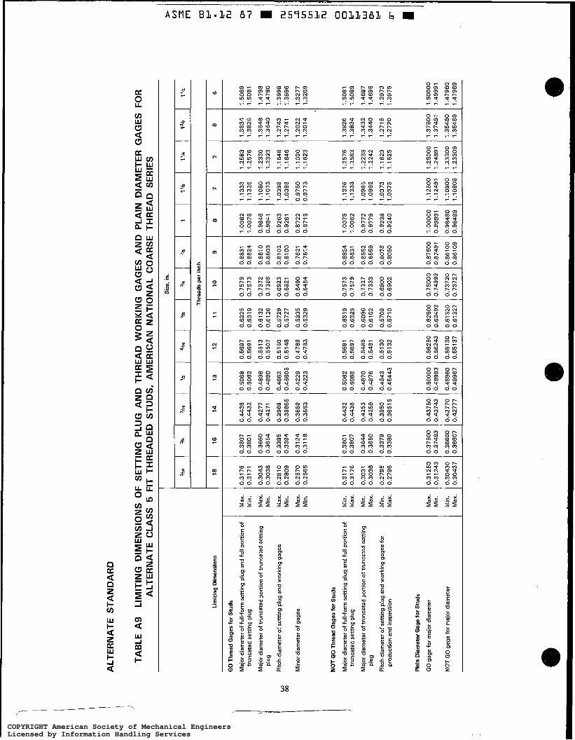
3
0
7
1.1333
1.1 326
1.1080
1,1073
1.0398
1.0396
0.9780
0.9773
1.1326
1.1333
1.0985
1.0992
1.0373
1.0375
ALT
ER
NA
TE S
TAN
DA
RD
7
1.2583
1.2576
1.2330
1.2323
1 .I 648
1 .I 646
1.1030
1.1 623
1.2576
1.2583
1.2235
1.2242
1.1623
1.1 625
TAB
LE A
9 LI
MIT
ING
DIM
EN
SIO
NS
OF
SE
TTIN
G P
LUG
AN
D T
HR
EA
D W
OR
KIN
G G
AG
ES
AN
D P
LAIN
DIA
ME
TER
GA
GE
S F
OR
A
LTE
RN
ATE
CLA
SS
5 F
IT T
HR
EA
DE
D S
TUD
S,
AM
ER
ICA
N N
ATI
ON
AL
CO
AR
SE
TH
RE
AD
SER
IES
GO
Thr
ead
Gag
es fo
r S
tuds
Maj
or d
iam
eter
of f
ull-f
orm
set
ting
plug
and
full
port
ion
of
trun
cate
d se
tting
plu
g
Maj
or d
iam
eter
of t
runc
ated
por
tion
of tr
unca
ted
setti
ng
Plu
g
Lim
iting
Dim
ensi
ons
Max
. M
in.
Max
. M
in.
0.5068
0.5062
0.4896
0.4890
0.4562
0.45605
0.4229
0.4223
Pitc
h di
amet
er o
f set
ting
plug
and
wor
king
gag
es
Min
or d
iam
eter
of
gage
s
0.5697
0.5691
0.5513
0.5507
0.5150
0.5148
0.4789
0.4783
Max
. M
in.
Max
. M
in.
0.6325
0.6319
0.6132
0.61 26
0.5729
0.5727
0.5335
0.5329
0.6319
0.6325
0.6096
0.6102
0.5708
0.5710
0.7579
0.7573
0.7372
0.7366
0.6923
0.6921
0.6490
0.6484
0.7573
0.7579
0.7327
0.7333
0.6900
0.6902
GO
gag
e fo
r m
ajor
dia
met
er
0.3807
0.3801
0.3660
0.3654
0.3395
0.3394
0.3124
0.31 18
NO
T G
O g
age
for
maj
or d
iam
eter
0.4438
0.4432
0.4277
0.4271
0.3968
0.39665
0.3659
0.3653
Max
. M
in.
Min
. M
ax.
NO
T G
O T
hrea
d G
ages
for
Stu
ds
Maj
or d
iam
eter
of
full-
form
set
ting
plug
and
full
port
ion
of
trun
cate
d se
tting
plu
g
Plu
g
prod
uctio
n an
d in
spec
tion
Maj
or d
iam
eter
of t
runc
ated
por
tion
of tr
unca
ted
setti
ng
Pitc
h di
amet
er o
f se
tting
plu
g an
d w
orki
ng g
ages
for
Pla
in D
iam
eter
Gag
e fo
r S
tuds
Siz
e, in
.
Min
. M
ax.
Min
. M
ax.
Min
. M
ax.
18
0.3801
0.3807
0.3644
0.3650
0.3379
0.3380
0.37500
0.37493
0.36600
0.36607
0.3176
0.3171
0.3043
0.3038
0.2810
0.2809
0.2570
0.2565
0.3171
0.3176
0.3031
0.3036
0.2795
0.2796
0.31250
0.31243
0.30430
0.30437
0.4432
0.4438
0.4253
0.4259
0.3950
0.39515
0.43750
0.43743
0.42770
0.42777
16
I 14
0.5062
0.5068
0.4870
0.4876
0.4543
0.45445
0.50000
0.49993
0.48960
0.48967
0.5691
0.5697
0.5485
0.5491
0.5 130
0.5132
0.56250
0.56243
0.55130
0.55137
0.62500
0.62493
0.61320
0.61327
13
I 12
0.75000
0,74993
0.73720
0.73727
1.12500
1.12491
1.10800
1.10809
1.25000
1.24991
1.23300
1.23309
Thr
eads
per
inch
11
I 10
9
0.8831
0.8824
0.8610
0.8603
0.8102
0.8100
0.7621
0.7614
0.8824
0.8831
0.8552
0.8559
0.8078
0.8080
0.87500
0.87491
0.86100
0.86109
8
1.0082
1.0075
0.9846
0.9841
0.9263
0.9261
0.8722
0.871 5
1.0075
1.0082
0.9772
0.9779
0.9238
0.9240
1 .oo
ooo
0.99991
0.98480
0.98489
6
1.3834
1.3826
1.3548
1.3540
1.2743
1.2741
1,2022
1.2014
1.3826
1.3834
1.3432
1.3440
1.2718
1.2720
1.37500
1.37491
1.35480
1.35489
6
1.5089
1.5081
1.4798
1.4790
1.3998
1.3996
1.3277
1.3269
1.5081
1.5089
1.4687
1.4695
1.3973
1.3975
1.50000
1.49991
1.47980
1.47989
COPYRIGHT American Society of Mechanical EngineersLicensed by Information Handling ServicesCOPYRIGHT American Society of Mechanical EngineersLicensed by Information Handling Services

ALT
ER
NA
TE S
TAN
DA
RD
%6
TAB
LE A
10
L
IMIT
ING
DIM
EN
SIO
NS
OF
THR
EA
D W
OR
KIN
G G
AG
ES
AN
D P
LAIN
DIA
ME
TER
GA
GE
S F
OR
ALT
ER
NA
TE C
LAS
S 5
FI
T TA
PP
ED
HO
LES
, A
ME
RIC
AN
NA
TIO
NA
L C
OA
RS
E T
HR
EA
D S
ERIE
S
3re
'/16
'12
9/76
5/a
31
4 7h
1
1 '/E
1 '14
1
3re
1 '12
Lim
iting
Dim
ensi
ons
GO
Thr
ead
Gag
es fo
r Ta
pped
Hol
es
Maj
or d
iam
eter
of
wor
king
gag
es
W
U3
P
itch
diam
eter
of w
orki
ng g
ages
NO
T G
O T
hrea
d G
ages
for
Tapp
ed H
oles
Maj
or d
iam
eter
of
wor
king
gag
es
Pitc
h di
amet
er o
f thr
ead
wor
king
gB
ges
for
prod
uctio
n an
d in
spec
tion
Pla
in D
iam
eter
Gag
es fo
r Ta
pped
Hol
es
GO
gag
es fo
r m
inor
dia
met
er
13
0.50
00
0.50
06
0.45
00
0.45
015
0.48
67
0.48
61
0.45
34
0.45
325
NO
T G
O g
ages
for
min
or d
iam
eter
12
0.56
25
0.56
31
0.50
84
0.50
86
0.54
80
0.54
74
0.51
19
0.51
17
-
Min
. M
ax.
Min
. M
ax.
Max
. M
in.
Max
. M
in.
Min
. M
ax.
Max
. M
in. -
0.43
1 30
0,
4313
7
0.A
3960
0.
4395
3
0.48
820
0.48
827
0.49
720
0.49
713
18
0.31
25
0.31
30
0.27
64
0.27
65
0.30
31
0.30
26
0.27
90
0.27
89
0.26
220
0.26
227
0.26
820
0.26
813
16
0.37
50
0.37
56
0.33
44
0.33
45
0.36
45
0.36
39
0.33
74
0.33
73
0.31
860
0.31
867
0.32
540
0.32
533
14
0.43
75
0.43
81
0.39
1 1
0.39
1 25
0.42
52
0.42
46
0.39
43
0.39
41 5
0.37
360
0.37
367
0.38
130
0.38
1 23
11
0.62
50
0.62
56
0.56
60
0.56
62
0.60
90
0.60
84
0.56
96
0.56
94
0.54
440
0.54
447
0.55
420
0.55
413
10
0.75
00
0.75
06
0.68
50
0.68
52
0.73
20
9.73
14
0.64
87
0.68
85
0.66
140
0.66
147
0.67
220
0.67
213
9
0.87
50
0.87
57
0.80
28
0.80
30
0.85
46
0.85
39
0.80
65
0.80
63
0.77
680
0.7
7 6 8 7
0.78
880
0.78
873
8
1 .oo
oo
1.00
07
0.91
88
0.91
90
0.97
66
0.97
59
0.92
25
0.92
23
0.89
010
0.89
01 9
0.90
360
0.90
351
7
1.12
50
1.12
57
1.03
22
1.03
24
1.09
78
1.09
71
1.03
59
1.03
57
0,99
980
0.99
989
1.01
520
1.
0151
1
7
1.25
00
1.25
07
1.15
72
1.15
74
1.22
28
1.22
21
1.16
09
1.16
07
1.12
480
1.12
489
1.14
020
1.1 4
01 1
6
1.37
50
1.37
58
1.26
67
1.26
69
1.34
26
1.34
1 8
1.27
04
1.27
02
1.22
860
1.22
869
1.24
660
1.24
651
6
1.50
00
1.50
08
1.39
1 7
1.39
1 9
1.46
79
1.46
71
1.39
57
1.39
55
1.35
360
1.35
369
1,37
160
1.37
1 51
COPYRIGHT American Society of Mechanical EngineersLicensed by Information Handling ServicesCOPYRIGHT American Society of Mechanical EngineersLicensed by Information Handling Services

20
0.44
27
0.44
22
0.43
03
0.42
98
0.40
97
0.40
96
0.38
81
0.38
76
0.44
22
0.44
27
0.42
95
0.43
00
0.40
84
0.40
85
0.43
750
0.43
743
0.43
030
0.43
037
20
0.50
55
0.50
50
0.49
28
0.49
23
0.47
25
0.47
24
0.45
09
0.45
04
0.50
50
0.50
55
0.49
23
0.49
28
0.47
1 2
0.47
13
0.50
000
0.49
993
0.49
280
0.49
287
GO
Thr
ead
Gag
es fo
r S
tuds
Maj
or d
iam
eter
of f
ull-f
orm
set
ting
plug
and
fu
ll po
rtio
n of
trun
cate
d se
ttin
g pl
ug
Maj
or d
iam
eter
of t
runc
ated
por
tion
of
Pitc
h di
amet
er o
f set
ting
plug
and
wor
king
trun
cate
d se
ttin
g pl
ug
gage
Max
. M
in.
Max
. M
in.
Max
. M
in.
Maj
or d
iam
eter
of f
ull-f
orm
set
ting
plug
and
fu
ll po
rtio
n o
f tru
ncat
ed s
ettin
g pl
ug
Maj
or d
iam
eter
of t
runc
ated
por
tion
of
trun
cate
d se
ttin
g pl
ug
Pitc
h di
amet
er o
f set
ting
plug
and
wor
king
ga
ges
for
prod
uctio
n an
d in
spec
tion
Pla
in D
iam
eter
Gag
es fo
r S
tuds
Min
. M
ax.
Min
. M
ax.
Min
. M
ax.
ALT
ER
NA
TE S
TAN
DA
RD
TAB
LE A
ll
LIM
ITIN
G D
IME
NS
ION
S O
F S
ETT
ING
PLU
G A
ND
TH
RE
AD
WO
RK
ING
GA
GE
S A
ND
PLA
IN D
IAM
ETE
R G
AG
ES
FO
R
ALT
ER
NA
TE C
LAS
S 5
FIT
TH
RE
AD
ED
STU
DS
, A
ME
RIC
AN
NA
TIO
NA
L FI
NE
TH
RE
AD
SE
RIE
S
D-
v) 3
m
Siz
e, in
.
Thr
eads
per
inch
28
24
2
4
18
18
1
6
14
14
12
1
2
12
1
2
Lim
iting
Dim
ensi
ons
0.25
44
0.25
39
0.24
38
0.24
33
0.23
07
0.23
06
0.21
52
0.21
47
0.25
39
0.25
44
0.24
46
0.24
51
0.22
96
0.22
97
0.25
000
0.24
993
0.24
380
0.24
387
0.31
72
0.31
67
0.30
59
0.30
54
0.28
96
0.28
95
0.27
1 6
0.27
1 1
0.31
67
0.31
72
0.30
59
0.30
64
0.28
84
0.28
85
0.31
250
0.
3124
3
0.30
590
0.30
597
0.37
99
0.37
94
0.36
84
0.36
79
0.35
23
0.35
22
0.33
43
0.33
38
0.37
94
0.37
99
0.36
86
0.36
91
0.35
1 1
0.35
1 2
0.37
500
0.37
493
0.36
840
0.36
847
0.56
86
0.56
81
0.55
43
0.55
38
0.53
20
0.53
185
0.50
80
0.50
75
0.56
81
0.56
86
0.55
41
0.55
46
0.53
05
0.53
065
0.56
250
0.56
243
0.55
430
0.55
437
0.63
1 1
0.63
06
0.61
68
0.61
63
0.59
45
0.59
435
0.57
05
0.57
00
0.63
06
0.63
1 1
0.61
66
0.61
71
0.59
30
0.59
315
0.62
500
0.62
493
0.61
680
0.61
687
0.75
65
0.75
59
0.74
10
0.74
04
0.71
53
0.71
51
0.68
82
0.68
76
0.75
59
0.75
65
0.74
02
0.74
08
0.71
37
0.71
39
0.75
000
0.74
993
0.74
100
0.74
107
0.88
21
0.88
1 5
0.86
52
0.86
46
0.83
51
0.83
49
0.80
42
0.80
36
0.88
1 5
0.88
21
0.86
36
0.86
42
0.83
33
0.83
35
0.87
500
0.87
491
0.86
520
0.86
529
1.00
75
1.00
69
0.99
02
0.98
96
0.96
05
0.96
03
0.92
96
0.92
90
1.00
69
1.00
75
0.98
90
0.98
96
0.95
87
0.95
89
1 .oo
ooo
0.99
991
0.99
020
0.9
9 0 2 9
1.13
31
1.13
25
1.11
38
1.11
32
1.07
84
1.07
82
1.04
23
1.04
1 7
1.13
25
1.13
31
1.11
19
1.11
25
1.07
64
1.07
66
1.12
500
1.1
2491
1.11
380
1.11
389
1.25
78
1.25
72
1.23
88
1.23
82
1.20
31
1.20
29
1.16
70
1.16
64
1.25
72
1.25
78
1.23
66
1.23
72
1.20
1 1
1.20
13
1.25
000
1.24
991
1.23
880
1.23
889
1.38
23
1.38
17
1.36
38
1.36
32
1.32
76
1.32
74
1.29
15
1.29
09
1.38
17
1.38
23
1.36
1 1
1.36
17
1.32
56
1.32
58
1.37
500
1.37
491
1.36
380
1.36
389
1.50
68
1.50
62
1.48
88
1.48
82
1.45
21
1.45
1 9
1.41
60
1.41
54
1.50
62
1.50
68
1.48
56
1.48
62
1.45
01
1.45
03
1.50
000
1.49
991
1.48
880
1.48
889
rLl
Ln
d3
Ln
Ln
t-l
Min
or d
iam
eter
of g
ages
NO
T G
O T
hrea
d G
ages
for
Stu
ds
Max
. M
in.
0
0
t-l
I+ W ? -I
GO
gag
es fo
r m
ajor
dia
met
er
Min
. I Ma
x.
NO
T G
O g
ages
for
maj
or d
iam
eter
M
in.
1 Max.
COPYRIGHT American Society of Mechanical EngineersLicensed by Information Handling ServicesCOPYRIGHT American Society of Mechanical EngineersLicensed by Information Handling Services
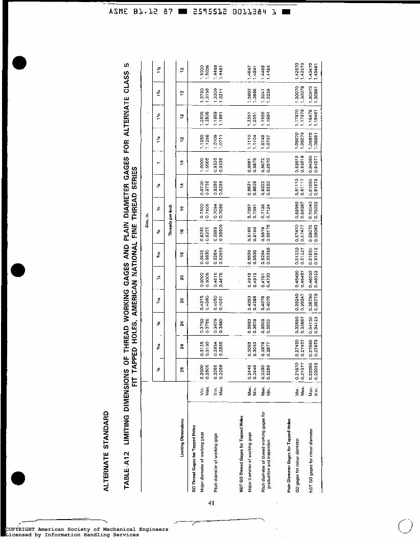
ALT
ER
NA
TE S
TAN
DA
RD
TAB
LE A
12
LI
MIT
ING
DIM
EN
SIO
NS
OF
THR
EA
D W
OR
KIN
G G
AG
ES
AN
D P
LAIN
DIA
ME
TER
GA
GE
S F
OR
ALT
ER
NA
TE C
LAS
S 5
FI
T TA
PP
ED
HO
LES,
AM
ER
ICA
N N
ATI
ON
AL
FIN
E TH
RE
AD
SER
IES
Sir
e, i
n.
Thre
ads
per i
nch
28
24
24
20
2
0
18
1
8
16
14
1
4
12
1
2
12
1
2
Lim
iting
Dlm
ensi
ons
GO
Thr
ead
Gag
es fo
r Tap
ped
Hol
es
Maj
or d
iam
eter
of
wor
king
gag
e
Pitc
h di
amet
er o
f w
orki
ng g
age
e M
in.
Max
.
Min
. M
ax.
Max
. M
in.
Max
. M
in.
Min
. M
ax.
Max
. M
in.
0.25
00
0.25
05
0.22
68
0.22
69
0.24
45
0.24
40
0.22
90
0.22
89
0.21
670
0.21
677
0.22
060
0.22
053
0.31
25
0.31
30
0.28
54
0.28
55
0.30
58
0.30
53
0.28
78
0.28
77
0.27
430
0.27
437
0.27
880
0.27
873
0.37
50
0.37
55
0.34
79
0.34
80
0.36
83
0.36
78
0.35
03
0.35
02
0.33
680
0.33
687
0.34
1 30
0.
3412
3
0.43
75
0.43
80
0.40
50
0.40
51
0.42
93
0.42
88
0.40
76
0.40
75
0.39
240
0.39
247
0.39
780
0.3
9 7 7 3
0.50
00
0.50
05
0.46
75
0.46
76
0.49
18
0.49
13
0.47
01
0.47
00
0.45
490
0.45
497
3.46
030
3.46
023
0.56
25
0.56
30
0.52
64
0.52
655
0.55
35
0.55
30
0.52
94
0.52
925
0.51
220
0.51
227
0.51
820
0.51
813
1.37
50
1.37
56
1.32
09
1.32
1 1
1.36
02
1.35
96
1.32
41
1.32
39
1.30
070
1.30
079
1.30
970
1.30
961
0.62
50
0.62
55
0.58
89
0.58
905
0.61
60
0.61
55
0.59
19
0.59
175
0.57
470
0.57
477
0.58
070
0.58
083
0.75
00
0.75
06
0.70
94
0.70
96
0.73
97
0.73
91
0.71
26
0.71
24
0.69
360
0.69
367
0.70
040
0.70
033
0.87
50
0.87
56
0.82
86
0.82
88
0.86
31
0.86
25
0.83
22
0.83
20
0.81
110
0.
81 1
1 7
0.81
880
0,81
873
1 .oo
oo
1.00
06
0.95
36
0.95
38
0.98
81
0.98
75
0.95
72
0.95
70
0.93
610
0.93
61 9
0.94
380
0.94
371
1.25
00
1.26
06
1.19
59
1.19
61
1.23
57
1.23
51
1.19
96
1.19
94
1,17
570
1.17
579
1.18
470
1.18
461
1.50
00
1.50
06
1.44
59
1.44
61
1.48
47
1.48
41
1.44
86
1.44
84
1.42
570
1.42
579
1.43
470
1.43
461
1.12
50
1.12
56
1.07
09
1.07
11
1.11
10
1.11
04
1.07
49
1.07
47
1.05
070
1.05
079
1.05
970
1.05
961
NO
T G
O T
hrea
d G
ages
for
Tapp
ed H
oles
Maj
or d
iam
eter
of w
orki
ng g
age
Pitc
h di
amet
er o
f thr
ead
wor
king
gag
es fo
r pr
oduc
tion
and
insp
ectio
n
Pla
in D
iam
eter
Gag
es fo
r Ta
pped
Hol
es
GO
gag
es fo
r m
inor
dia
met
er
NO
T G
O g
ages
for
min
or d
iam
erer
COPYRIGHT American Society of Mechanical EngineersLicensed by Information Handling ServicesCOPYRIGHT American Society of Mechanical EngineersLicensed by Information Handling Services

ASME Bl.32 87 W 2575532 OOLL385 3 W
APPEND11 B Specifications for Elastic Interference-Fit Thread
(This Appendix is not part of ASMEIANSI B I . 12-1 987, and is included for information purposes only.)
B I INTRODUCTION
Appendix B contains useful information that is sup- plementary to this Standard.
The elastic interference-fit threads are precision threads. The stud and hole are matched for maximum interference. Studs are hardened steel, CRES (corrosion resistant steel), Monel (Monel400), B16 (ASTM A 193 High Temperature Alloy Steel B16), and K Monel (Monel K500) set in HY-80 steel (80,000 psi yield strength), HTS (high tensile steel hull plate), and cast Monel (Monel 410). Specifications have also proven satisfactory for nonferrous materials. With good geom- etry parts, successful interference fits with satisfactory resistance to breakloose torque and minimum distortion to the thread form are common. Percentages of interfer- ence metal per turn, compared to maximum interference for NC-5 HF/IF at loo%, are greatly reduced for the elastic flow interference-fit thread (see Appendix D, Ta- ble Dl). These threads are used in ship construction.
B 2 THREAD DESIGNATION
B2.1 Class 5 External Thread Made in Monel and Hard Ferrous Material
EXAMPLE: 0.625-11 NC-5 HFM where
0.625 = nominal size 11 = threads per inch N = American National thread form C = coarse thread series 5 = Class 5 Modified tolerance
HF = hard ferrous external thread a M = Monel and K Mond
B2.2 Class 5 Internal Thread Made in Monel, K Monei, and Entire Ferrous Material Hardness Range
EXAMPLE: 0.625-11 NC-5 E M where
0.625 = nominal size 11 = threads per inch N = American National thread form C = coarse thread series 5 = Class 5 Modified tolerance I = internal thread
FM = ferrous, Monel, and K Monel materials
B3 EXTERNAL AND INTERNAL THREADS COMPARED TO NC-5
Examination of Tables B1, B2, and B3 on limits of size, tap drill size, length of engagement, and torque reveals the following.
83.1 Tolerances
5 threads for ferrous materials. Tolerances are smaller than standard National Class
B3.2 External Thread
(U) Maximum major diameter is much smaller than the standard NC-5 threads. The major diameter allow- ance is approximately equal to 0.020d + 0.001 in.
(b) Major diameter tolerance is 0.002 in. for 'h, %6,
and 3/s sizes, 0.003 in. for 7/i6 size, and 0.004 in. for V2
in. size and larger. (c) Pitch diameter is always larger than basic pitch
diameter. (d) Pitch diameter tolerance is 0.001 in. for 3/8 in.
and smaller and 0.002 in. for 9/16 in. and larger.
43
COPYRIGHT American Society of Mechanical EngineersLicensed by Information Handling ServicesCOPYRIGHT American Society of Mechanical EngineersLicensed by Information Handling Services
(e) Maximum minor diameter is smaller than basic
( f ) Minimum minor diameter is specified. by 0.006 in. to 0.026 in.
B3.3 internal Thread
(a) Minimum minor diameter is from 0.005 in. to 0.041 in. greater than basic.
(b) Minor diameter tolerance is from 0.008 in. to 0.027 in.
(c) Minimum pitch diameter is 0.0003 in. to 0.0023 in. larger than basic pitch diameter.
( d ) Pitch diameter tolerances increase from 0.0005 in. to 0.0011 in. between '14 in. and 2 in. sizes.
(e) Minimum major diameter is nominal size. ( f ) Taps have a minimum and maximum pitch di-
ameter tolerance specified.
B3.4 Torque
For assemblies made without a locking resin, the minimum assembly torque shall meet the minimum torque values tabulated in Table B3 or shall be at least one and one-half times the breakloose torque.
B4 APPLICATION PRACTICE FOR NEW AND REWORKED EXTERNAL AND INTERNAL THREADS
B4.1 Additional Conditions of Usage (See Section I O )
The following are for elastic interference-fit threads on which satisfactory application of products made to dimensions in Tables B1 and B2 are predicated.
B4.1 .I External Thread. Studs are measured by size-indicating gages and selected to be within 0.0005 in. of the maximum-interference functional size speci- fied in Table B3 for a reworked tapped hole. The stud shall be of uniform quality and condition and shall not have fins, seams, laps, cracks, burrs, an irregular sur- face, or other injurious defects detrimental to the per- formance of the part. The geometry of the stud requires that the measured difference between functional size and pitch diameter size does not exceed 50% of the pitch diameter tolerance.
B4.1.2 Internal Thread. Tapped holes are mea- sured by size-indicating gages. Negative taper in hole (small at entering end) is not permitted. Holes shall be bottom tapped. Geometry of profile and hole is con- trolled by requiring the difference between measured functional size and pitch diameter size to be within 50%
of the pitch diameter tolerance. A hole with a defective thread profile, prior to reassembly, is repaired by retap- ping with the next larger tap until the profile is restored. Holes are remeasured and studs are matched to holes. In other cases, holes are enlarged to tabulated size to accept stock studs intended for reworking.
B4.1.3 Pitch Diameter interference (a) Maximum Pitch Diameter Interference. Selection
of thread assemblies for maximum pitch diameter inter- ference will ensure that the torque values tabulated in Table B3 will be met.
(b) Minimum Pitch Diameter Interference. An ex- amination of the minimum interference column in Table B3 reveals zero interference on pitch diameter. In prac- tice, when measured external and internal threads are both at minimum material, variations within acceptable limits for lead, angle, taper, roundness, etc., do provide some functional metal-to-metal interference. If the as- sembly does not meet the torque requirements stated in para. B3.4, a resin sealant may be required to lock the assembly for those applications when sealants are ac- ceptable.
B4.1.4 Resin Sealants. Under specified condi- tions, reworked assemblies with poor interference or clearance may be locked together with anaerobic seal- ant. These assemblies may not be subject to tempera- tures above 200°F.
Before applying sealant, clean parts with oil-free cleaner, dry, and prime with MIL-S-22773 Grade N. Let dry. Use sealant MIL-S-22773 Grade AV when clearance is under 0.005 in. and Grade AVV for larger clearances.
B4.1.5 Surface Roughness. The optimum surface roughness for both external and internal threads was found to be 63 pin. Ra. Values under 125 pin. Ra are recommended. Rougher surfaces are fractured and may release bits of metal during the engagement and get trapped in the interference zone. This results in the need for greater torque with heat generation which may pro- duce more assembly failures. Surface roughness less than 63 pin. Ra may inhibit flow of lubricant, permit buildup of hydraulic pressure, and require higher assem- bly torque.
B4.1.6 Driving Speed. Torque should be applied smoothly and evenly. Torque readings should contin- ually increase as the length of engagement becomes greater. When K Monel studs are driven into Monel or K Monel holes, a great deal of heat is generated. Driv- ing should be stopped several times to let the heat dis- sipate. When excessive torque builds up, backing off one or two turns before driving the stud home may re-
COPYRIGHT American Society of Mechanical EngineersLicensed by Information Handling ServicesCOPYRIGHT American Society of Mechanical EngineersLicensed by Information Handling Services
duce the torque 30 or 40 lb-ft on a %3 in. thread. The mechanic must determine the optimum driving speed, because type of lubricant, hardness, surface texture, and materials vary with the application.
B4.1.7 Assembly and Disassembly. A set stud must resist rotation when seating and breaking away the prevailing torque nut. Otherwise, the assembly is a fail- ure. After studs are seated, the end faces are scribed with lines, all directed toward the center of the compo- nent or some designated point. Rotation resulting from movement of prevailing torque nut can be easily rec- ognized when lines do not line up. When studs are re- moved during overhaul, questionable profiles are measured and reworked, if necessary. Reapplication up to four times without reworking is feasible, but assem- bly torque may decrease 60 % .
B4.1.8 Acceptability. Acceptability of elastic in- terference-fit threads shall be determined based upon System 23 of ANSUASME B1.3M. The following mod- ifications of System 23 apply.
I
(a) Size-indicating gages are required. (b) Roundness, lead variation, flank angle variation
runout, and surface texture are not required.
NOTE: Application may require one or more of these measurements.
B5 GAGING
B5.1 Limits of Size
The limits of size for maximum-material setting gages, specifically for plug gages for external threads and solid ring gages for internal threads, are tabulated in Table B4. Indicating gages need only one reference gage for setting.
85.2 Unified Class 3A and 3B Setting Gages
Unified Class 3A and 3B setting gages, as tabulated in ANSUASME B1.2, may be substituted for the gages in Table B4 if the indicating gages have sufficient travel.
COPYRIGHT American Society of Mechanical EngineersLicensed by Information Handling ServicesCOPYRIGHT American Society of Mechanical EngineersLicensed by Information Handling Services
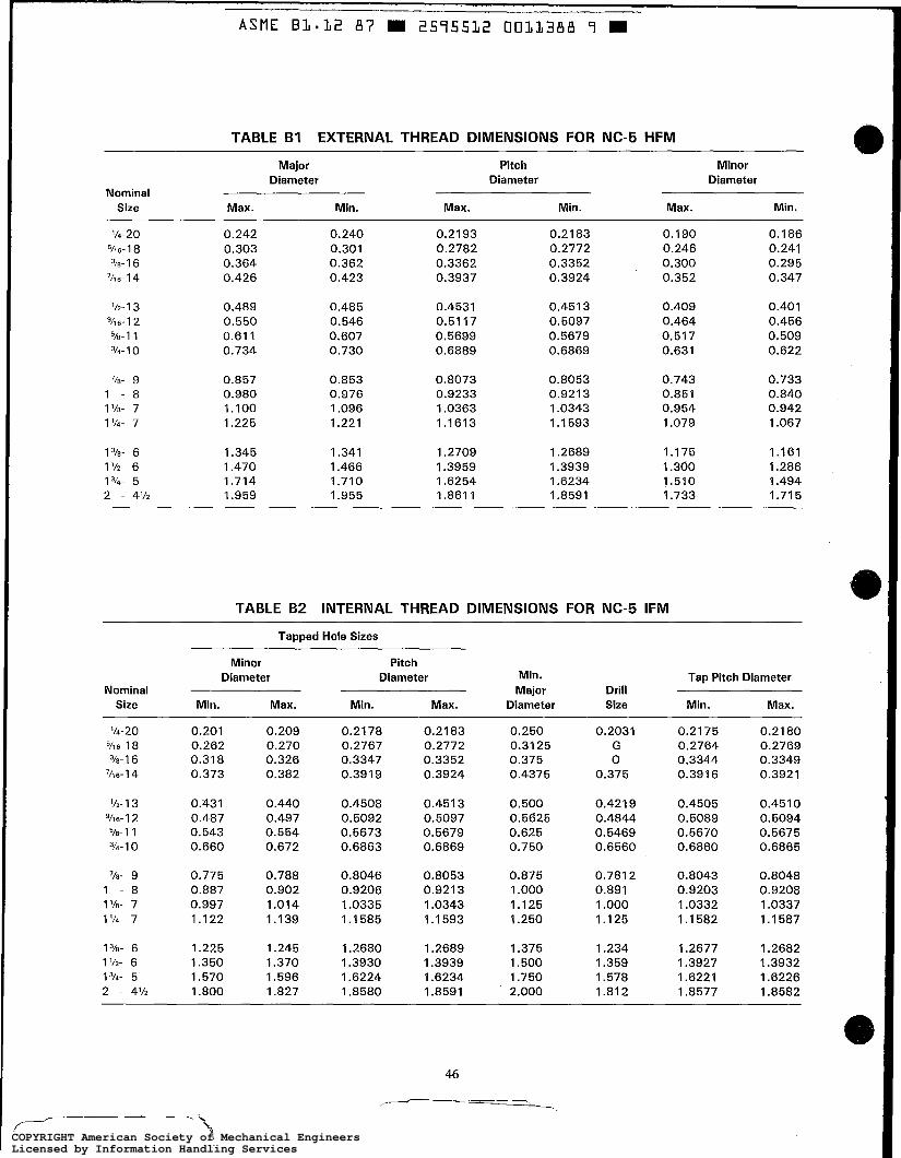
ASflE B 1 . 1 2 87 = 2595512 0011388 9 B
TABLE B I EXTERNAL THREAD DIMENSIONS FOR NC-5 HFM
Major Pitch Minor Diameter Diameter Diameter
Nominal Size Max. Min. Max. Min. Max. Min.
’14-20 5/i 6- 1 a
3iü- I 6 ‘116- 1 4
’/2- 1 3 VI 6- I 2
510- 1 1 314- 1 0
’18- 9 I - 8 1’18- 7 1 114- 7
1 31ü- 6 1’12- 6 1314- 5 2 - 4’12
0.242 0.303 0.364 0.426
0.489 0.550 0.61 1 0.734
0.857 0.980 1.100 1.225
1.345 1.470 1.714 1.959
0.240 0.301 0.362 0.423
0.485 0.546 0.607 0.730
0.853 0.976 1.096 1.221
1.341 1.466 1.710 1.955
0.21 93 0.2782 0.3362 0.3937
0.4531 0.51 17 0.5699 0.6889
0.8073 0.9233 1.0363 1.1613
1.2709 1.3959 1.6254 I .a61 I
0.21 83 0.2772 0.3352 0.3924
0.451 3 0.5097 0.5679 0.6869
0.8053 0.9213 1.0343 1.1593
I
I .a591
1.3939 1.6234
0.190 0.246 0.300 0.352
0.409 0.464 0.517 0.631
0.743
0.954 1.079
1.175 1.300 1.510 1.733
0.851
0.186 0.241 0.295 0.347
0.401 0.456 0.509 0.622
0.733
0.942 1.067
1.161 1.286 1.494 1.71 5
0.840
TABLE B 2 INTERNAL THREAD DIMENSIONS FOR NC-5 IFM
Tapped Hole Sizes
Minor Pitch Diameter Diameter Min. Tap Pitch Diameter
Size Min. Max. Min. Max. Diameter Size Min. Max. Nominal Major Drill
’14-20 51’ 6- 1 a
7~ 6- 1 4
‘12- 1 3 91’ 6- 1 2
510-1 1 3/4- 1 0
3/ü- 1 6
’18- 9 I - 8 1 ’18- 7 1114- 7
1 3/~- 6 1 ‘12- 6 1314- 5 2 - 4’12
0.201 0.262
0.373
0.431
0.543 0.660
0.775
0.997 1.122
1.225 1.350 1.570
0.318
0.487
0.887
I .aoo
0.209 0.270 0.326 0.382
0.440 0.497 0.554 0.672
0.788 0.902 1.014 1.139
1.245 1.370 1.596 I .a27
0.2178 0.2767 0.3347 0.391 9
0.4508
0.6863
0.5092 0.5673
0.8046 0.9206 1.0335 1.1585
I .2680
I ,8580
1.3930 1.6224
0.21 83 0.2772 0.3352 0.3924
0.451 3 0.5097 0.5679 0.6869
0.8053 0.9213 1.0343 1.1593
I
I .a591
1.3939 1.6234
0.250 0.31 25 0.375 0.4375
0.500 0.5625 0.625 0.750
0.875 1 .ooo 1.125 1.250
1.375 1.500 1.750 2.000
0.2031 G 0
0.375
0.421 9
0.5469 0.6560
0.4844
0.7812 0.891 1 .ooo 1.125
1.234 1.359
1.812 I .578
0.2175 0.2764 0.3344 0.3916
0.4505
0.5670 0.5089
0.6860
0.8043 0.9203 1.0332 1.1582
1.2677 1.3927 1.6221 I .a577
0.2180 0.2769 0.3349 0.3921
0.451 0 0.5094 0.5675 0.6865
0.8048 0.9208 1.0337 1.1587
I .ma2 1.3932 1.6226 1.8582
46
COPYRIGHT American Society of Mechanical EngineersLicensed by Information Handling ServicesCOPYRIGHT American Society of Mechanical EngineersLicensed by Information Handling Services
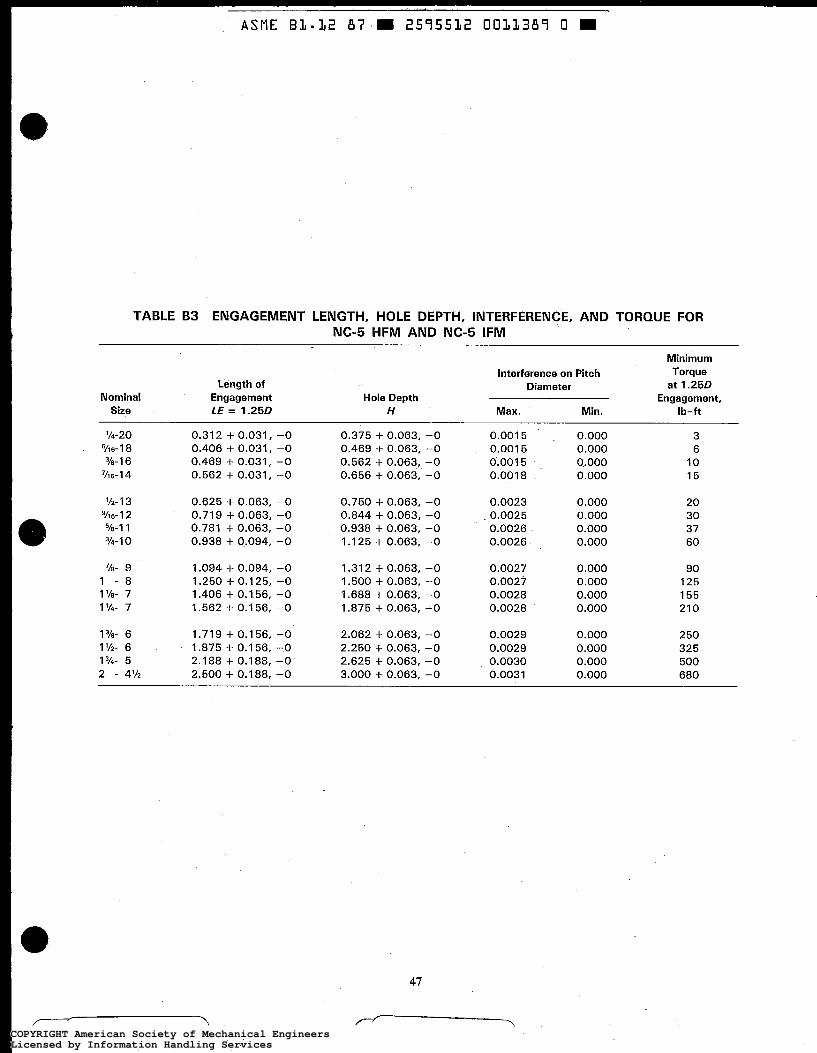
TABLE B3 ENGAGEMENT LENGTH, HOLE DEPTH, INTERFERENCE, AND TORQUE FOR NC-5 HFM AND NC-5 IFM
Minimum
at 1.250 Interference on Pitch Torque
Length of Diameter Nominal Engagement Hole Depth Engagement,
Size LE = 1.250 H Max. Min. Ib-ft
'14-20 6- I 8
3/8-1 6 71' 6- 1 4
'12- 1 3 911 6- 1 2 Ta-1 1 3/4- I 0
716- 9 1 - 8 1 '/a- 7 1 '14- 7
0.312 + 0.031, -0 0.406 + 0.031, -0 0.469 + 0.031, -0 0.562 + 0.031, -0 0.625 + 0.063, -0 0.719 + 0.063, -0 0.781 + 0.063, -0 0.938 + 0.094, -0 1.094 + 0.094, -0 1.250 + 0.1 25, -0 1.406 + 0.156, -0 1.562 + 0.1 56, -0
0.375 + 0.063, -0 0.469 + 0.063, -0 0.562 + 0.063, -0 0.656 + 0.063, -0 0.750 + 0.063, -0 0.844 + 0.063, -0 0.938 + 0.063, -0 1.125 + 0.063, -0 1.31 2 + 0.063, -0 1.500 + 0.063, -0 1.688 + 0.063, -0 1.875 + 0.063, -0
0.001 5 0.001 5 0.001 5 0.001 8
0.0023 0.0025 0.0026 0.0026
0.0027
0.0028 0.0028
0.0027
0.000 0.000 0.000 0.000
0.000 0.000 0.000 0.000
0.000 0.000 0.000 0.000
3 6 10 15
20 30 37 60
90 125 155 21 0
1 '/a- 6 1.719 + 0.156, -0 2.062 + 0.063, -0 0.0029 0.000 250 1 '12- 6 1.875 + 0.156, -0 2.250 + 0.063, -0 0.0029 0.000 325 1314- 5 2.188 + 0.188, -0 2.625 + 0.063, -0 0.0030 0.000 500 2 - 4'12 2.500 + 0.188, -0 3.000 + 0.063, -0 0.0031 0.000 680
47
COPYRIGHT American Society of Mechanical EngineersLicensed by Information Handling ServicesCOPYRIGHT American Society of Mechanical EngineersLicensed by Information Handling Services

Nominal Size
1
1/4-20
% 6- 1 8
'1s- 1 6
7i1 6- 1 4
'12- 1 3
9/i6-12
5%-1 1
314- 1 0
'10- 9
1 - 8
114- 7
1'14- 7
1 '18- 6
1 '12- 6
I V4- 5
2 - 4'12
TABLE B 4 SETTING GAGES FOR NC-5 HFM AND NC-5 IFM
Full-Form Major Diameter
2
0.2420 0.2425 0.3030 0.3035
0.3640 0.3646 0.4260 0.4266
0.4890 0.4896 0.5500 0.5506
0.61 10 0.61 16 0.7340 0.7346
0.8570 0.8577 0.9800 0.9807
1.1000 1.1007 1.2250 1.2257
1.3450 1.3458 1.4700 1.4708
1.7140 1.7148 1.9590 1.9598
W Thread-Setting Plugs, Maximum Material
Pitch Diameter [Note (1 )I
3
0.2193 0.2192 0.2782 0.2781
0.3362 0.3361 0.3937 0.3936
0.4531 0.4530 0.51 17 0.51 15
0.5699 0.5697 0.6889 0.6887
0.8073 0.8071 0.9233 0.9231
1.0363 1.0361 1.1613 1.1611
1.2709 1.2707 1.3959 1.3957
1.6254 1.6252 1.861 1 1.8608
Maximum Minor Diameter
4
0.1900 0.1895 0.2460 0.2455
0.3000 0.2994 0.3520 0.3514
0.4090 0.4084 0.4640 0.4634
0.51 70 0.5164 0.6310 0.6304
0.7430 0.7423 0.8510 0.8503
0.9540 0.9533 1.0790 1.0783
1.1750 1.1742 1.3000 1.2992
1.5100 1.5092 1.7330 1.7322
W Thread-Setting Rings, Maximum Material
Pitch Diameter [Note (1 )I
5
0.2178 0.21 79 0.2767 0.2768
0.3347 0.3348 0.391 9 0.3920
0.4508 0.451 0 0.5092 0.5094
0.5673 0.5675 0.6863 0.6865
0.8046 0.8048 0.9206 0.9208
1.0335 1.0337 1.1585 1.1587
1.2680 1.2682 1.3930 1.3932
1.6224 1.6226 1.8580 1.8582
Minimum Minor Diameter
6
0.2010 0.2005 0.2620 0.261 5
0.3180 0.31 74 0.3730 0.3724
0.4250 0.4244 0.4870 0.4864
0.5430 0.5424 0.6560 0.6554
0.7750 0.7743 0.8870 0.8863
0.9970 0.9963 1.1220 1.1213
1.2250 1.2242 1.3500 1.3492
1 .5700 1.5692 1.8000 1.7992
NOTE: (I 1 Pitch diameter tolerances greater than W are acceptable for setting indicating gages provided the indicating gage is set t o the
calibrated pitch diameter.
48
COPYRIGHT American Society of Mechanical EngineersLicensed by Information Handling ServicesCOPYRIGHT American Society of Mechanical EngineersLicensed by Information Handling Services
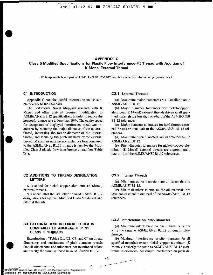
' ASME BI-12 87 m 2575512 OOLL37L 7 m
APPENDIX C Class 5 Modified Specifications for Plastic Flow Interference-Fit Thread with Addition of
K Monel External Thread
(This Appendix is not part of ASME/ANSI B I . 12-1 987, and is included for information purposes only.)
C I INTRODUCTION
Appendix C contains useful information that is sup- plementary to the Standard.
The Portsmouth Naval Shipyard research with K Monel and other material required modification to ASME/ANSI B1.12 specifications in order to reduce the nonconformance rate to less than 10 % . The cavity space for acceptance of displayed interference metal was in- creased by reducing the major diameter of the external thread, increasing the minor diameter of the internal thread, and reducing the pitch diameter of the external thread. Maximum interference metal per turn compared to the ASME/ANSI B1.12 threads is less for the Mod- ified Class 5 plastic flow interference thread (see Table Dl).
C2 ADDITIONS TO THREAD DESIGNATION LETTERS
K is added for nickel-copper-aluminum (K Monel) external threads.
S is added after the last letter of ASME/ANSI B1.12 designations for Special Modified Class 5 external and internal threads.
C3 EXTERNAL AND INTERNAL THREADS COMPARED TO ASME/ANSI B I . I 2 CLASS 5 THREADS
Examination of Tables C1, C2, C3, and C4 on thread dimensions and interference of pitch diameter reveals that all dimensions and tolerances not mentioned below are exactly the same as those in ASME/ANSI B1,12.
C3.1 External Threads
(a) Maximum major diameters are all smaller than in
(b) Major diameter tolerances for nickel-copper- aluminum (K Monel) external threads driven in all spec- ified materials are less than one-half of the ASME/ANSI B1.12 tolerances.
(c) Major diameter tolerances for hard ferrous exter- nal threads are one-half of the ASME/ANSI B1.12 tol- erances.
(d) Maximum pitch diameters are all smaller than in ASME/ANSI B1.12.
(e) Pitch diameter tolerances for nickel-copper-alu- minum (K Monel) external threads are approximately one-third of the ASME/ANSI B1.12 tolerances.
' ASME/ANSI B1.12.
C3.2 Internal Threads
(a) Minimum minor diameters are all larger than in ASME/ANSI B1.12.
(b) Minor diameter tolerances for all materials are less than or equal to one-half of the ASME/ANSI B1.12 tolerances.
C3.3 Interference on Pitch Diameter
(a) Minimum interference on pitch diameter is ex- actly the same as ASME/ANSI B1.12 minimum inter- ference.
(b) Maximum Interference on pitch diameter for all specified materials except nickel-copper-aluminum (K Monel) is exactly the same as ASME/ANSI B1.12 max- imum interference. Maximum interference on pitch di-
49
COPYRIGHT American Society of Mechanical EngineersLicensed by Information Handling ServicesCOPYRIGHT American Society of Mechanical EngineersLicensed by Information Handling Services
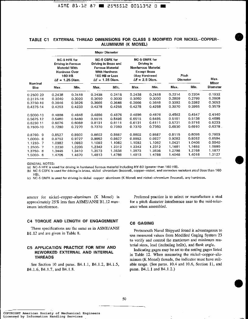
A S M E B3.12 87 2575532 0033372 0
TABLE C I EXTERNAL THREAD DIMENSIONS FOR CLASS 5 MODIFIED FOR NICKEL-COPPER- ALUMINUM (K MONEL)
Major Diameter
NC-5 HFK for Driving in Ferrous
Material With Hardness Over
160 HB LE = 1.25 Diam.
Size Max. Min. Nominal
NC-5 CSFK for Driving in Brass and
Ferrous Material With Hardness 160 HB or Less
LE = 1.25 Diam.
Max. Min.
NC-5 ONFK for Driving in
Nonferrous Material Except Brass
(Any Hardness) Pitch LE = 2.5 Diam. Diameter Max.
Minor Max. Min. Max. Min. Diameter
0.2500-20 0.31 25-1 8 0.3750-1 6 0.4375-14
0.5000-1 3 0.5625-12 0.6250-1 1 0.7500-1 0
0.8750- 9 1.0000- 8 1.1250- 7 1.2500- 7 1.3750- 6 1.5000- 6
0.2438 0.3040 0.3646 0.4253
0.4866 0.5480 0.6076 0.7290
0.8527 0.9752 1.0982 1.2230 1.3445 1.4705
0.241 8 0.3020 0.3626 0.4233
0.4846 0.5460 0.6056 0.7270
0.8502 0.9727 1.0952 1.2200 1.3410 1.4670
0.2438 0.3050 0.3666 0.4278
0.4896 0.551 5 0.6131 0.7370
0.8602 0.9852 1.1092 1.2342 1.3573 1.4813
0.241 8 0.3030 0.3646 0.4258
0.4876 0.5495 0.61 11 0.7350
0.8587 0.9827 1.1062 1.231 2 1.3538 1.4788
0.2438 0.3050 0.3666 0.4278
0.4896 0.5515 0.6131 0.7370
0.8602 0.9852 1.1092 1.2342 1.3573 1.4813
0.241 8 0.3030 0.3646 0.4258
0.4876 0.5495 0.61 11 0.7350
0.8587 0.9827 1.1062 1.231 2 1.3538 1.4788
0.2214 0.2809 0.3392 0.3970
0.4562 0.5151 0.5731 0.6930
0.81 15 0.9282 1.0431 1.1681 1.2798 1.4048
0.2204 0.2799 0.3382 0.3955
0.4547 0.5136 0.5716 0.6910
0.8095 0.9262 1.0406 1.1656 1.2768 1.401 8
0.1932 0.2508 0.3053 0.3579
0.4140 0.4695 0.5233 0.6378
0.7503 0.8594 0.9640 1.0890 1.1877 1.31 27
GENERAL NOTES: (a) NC-5 HFK is used for driving in hardened ferrous material including HY-80 (greater than 160 HB). (b) NC-5 CSFK is used for driving in brass, nickel-chromium (Inconel), copper-nickel, and corrosion resistant steer (less than 160
HB). (c) NC-5 ONFK is used for driving in nickel-copper-aluminum (K Monel) and nickel-chromium (Inconel), any hardness.
ameter for nickel-copper-aluminum (K Monel) is approximately 25 % less than ASME/ANSI B1.12 max- imum interference.
C4 TORQUE AND LENGTH OF ENGAGEMENT
These specifications are the same as in ASMEIANSI B 1.12 and are given in Table 8.
C5 APPLICATION PRACTICE FOR NEW AND REWORKED EXTERNAL AND INTERNAL THREADS
See Section 10 and paras. B4.1.1, B4.1.2, B4.1.5, B4.1.6, B4.1.7, andB4.1.8.
50
Preferred practice is to select or manufacture a stud for a pitch diameter interference near to the mid-toler- ance when assembled.
C6 GAGING
Portsmouth Naval Shipyard found it advantageous to use measured values from Modified Gaging System 23 to verify and control the maximum and minimum ma- terial sizes, lead (including helix), and flank angle.
Indicating gages may be set to the setting gages listed in Table 12. When measuring the nickel-copper-alu- minum (K Monel) threads, the indicator must have suit- able range. (See paras. 10.4 and 10.6, Section 11, and paras. B4.1.1 and B4.1.2.)
COPYRIGHT American Society of Mechanical EngineersLicensed by Information Handling ServicesCOPYRIGHT American Society of Mechanical EngineersLicensed by Information Handling Services

T
ASME 81.12 87 = 2595512 0011393 2 =
TABLE C2 EXTERNAL THREAD DIMENSIONS FOR CLASS 5 MODIFIED FOR GREATER CAVITY SPACE
Major Diameter
NC-5 HFS for Driving in Ferrous
Material With Hardness Over
160 HB LE = 1.25 Diam.
Size Max. Min. Nominal
NC-5 CSFS for Driving in Brass and
Ferrous Material With Hardness 160 HB or Less
LE = 1.25 Diam.
Max. Min.
NC-5 ONFS for Driving in
Nonferrous Material Except Brass
(Any Hardness) Pitch LE = 2.5 Diam. Diameter Max.
Minor Max. . Min. Max. Min. Diameter
0.2500-20 0.2449 0.2418 0.2449 0.2418 0.2449 0.2418 0.2230 0.2204 0.1932 0.31 25-18 0.3050 0.3020 9.3060 0.3030 0.3060 0.3030 0.2829 0.2799 0.2508 0.3750-16 0.3658 0.3626 0.3678 0.3646 0.3678 0.3646 0.3414 0.3382 0.3053 0.4375-1 4 0.4269 0.4233 0.4294 0.4258 0.4294 0.4258 0.3991 0.3955 0.3579
0.5000-13 0.4883 0.4846 0.4913 0.4876 0.4913 0.4876 0.4584 0.4547 0.4140 0.5625-12 0.5500 0.5460 0.5538 0.5495 0.5538 0.5495 0.5176 0.5136 0.4695 0.6250-1 1 0.6098 0.6056 0.6153 0.61 11 0.61 53 0.61 11 0.5758 0.5716 0.5233 0.7500-10 0.731 5 0.7270 0.7395 0.7350 0.7395 0.7350 0.6955 0.6910 0.6378
0.8750- 9 0.8531 0.8502 0.8636 0.8587 0.8636 0.8587 0.8144 0.8095 0.7503 1.0000- 8 0.9781 0.9727 0.9881 0.9827 0.9881 0.9827 0.9316 0.9262 0.8594 1.1250- 7 1.1011 1.0952 1.1121 1.1062 1.1121 1.1062 1.0465 1.0406 0.9640 1.2500- 7 1.2260 1.2200 1.2371 1.2312 1.2371 1.2312 1.1715 1.1656 1.0890 1.3750- 6 1.3485 1.3410 1.3609 1.3538 1.3609 1.3538 1.2839 1.2768 1.1877 1.5000- 6 1.4740 1.4670 1.4859 1.4788 1.4859 1.4788 1.4089 1.4018 1.3127
GENERAL NOTES: (a) NC-5 HFS is used for driving in hardened ferrous material including HY-80 (greater than 160 HB). (b) NC-5 CSFS is used for driving in brass, nickel-chromium (Inconel), copper-nickel, and corrosion resistant steel (less than 160
HB). (c) NC-5 ONFS is used for driving in nickel-copper-aluminum (K Monel) and nickel-chromium (Inconel), any hardness.
COPYRIGHT American Society of Mechanical EngineersLicensed by Information Handling ServicesCOPYRIGHT American Society of Mechanical EngineersLicensed by Information Handling Services
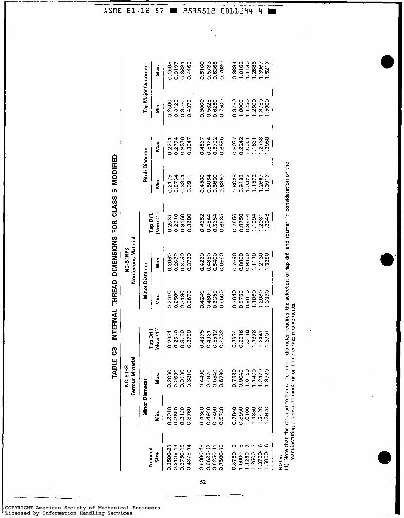
TAB
LE C
3 IN
TER
NA
L TH
RE
AD
DIM
EN
SIO
NS
FO
R C
LAS
S 5
MO
DIF
IED
NC
-5 IF
S
NC
-5 IN
FS
Fer
rous
Mat
eria
l N
onfe
rrou
s M
ater
ial
Min
or D
iam
eter
M
inor
Dia
met
er
Pitc
h D
iam
eter
T
ap M
ajor
Dia
met
er
Siz
e M
in.
Max
. [N
ote
(1 11
Min
. M
ax.
[Not
e (1
11 M
in.
Max
. M
in.
Max
. N
omin
al
Tap
Dril
l T
ap D
rill
0.2
500-
20
0.31
25-
1 8
0.37
50-1
6
0.43
75-1
4
0.20
10
0.25
80
0.31
30
0.37
60
0.20
60
0.26
30
0.31
80
0.
381
0
0.20
31
0.26
10
0.31
60
0.
3780
0.20
10
0.25
80
0.3
130
0.36
70
0.20
60
0.26
30
0.31
80
0.37
20
0.20
31
0.26
10
0.31
60
0.36
80
0.21
75
0.27
64
0.33
44
0.39
1 1
0.22
01
0.27
94
0.33
76
0.39
47
0.25
00
0.31
25
0.37
50
0.43
75
0.25
65
0.31
97
0.38
31
0.44
68
0.50
00-1
3 0.
5625
-1 2
0.
6250
-1 1
0.75
00-1
0
0.43
50
0.49
20
0.54
90
0.67
30
0.44
00
0.49
70
0.55
40
0.67
80
0.43
75
0.49
21
0.55
12
0.67
32
0.42
40
0.48
00
0.53
50
0.65
00
0.42
90
0.48
50
0.54
00
0.65
50
0.42
52
0.48
44
0.53
54
0.65
35
0.45
00
0.50
84
0.56
60
0.68
50
0.45
37
0.51
24
0.57
02
0.68
95
0.50
00
0.56
25
0.62
50
0.75
00
0.51
00
0.57
33
0.63
68
0.76
30
0.87
50-
9 1.
0000
- 8
1.12
50-
7 1.
2500
- 7
1.37
50-
6 1.
5000
- 6
0.78
40
0.89
90
1.01
00
1.13
50
1.24
20
1.36
70
0.78
90
0.90
40
1.01
50
1.14
00
1.24
70
1.37
20
0.78
74
0.90
1 6
1.01
18
1.13
78
1.24
41
1.37
01
0.76
40
0.87
50
0.98
10
1.10
60
1.20
80
1.33
30
0.76
90
0.88
00
0.98
60
1.11
10
1.21
30
I .33
ao
0.76
56
0.87
50
0.98
44
1.10
94
1.20
31
1.33
46
0.80
28
0.91
88
1.03
22
1.15
72
1.26
67
1.39
17
0.80
77
0.92
42
1.03
81
1.16
31
1.27
38
1.39
88
0.87
50
1 .oo
oo
1.12
50
1.25
00
1.37
50
1 .50
00
0.88
94
1.01
62
1.14
36
1.26
86
1.39
67
1.52
1 7
NO
TE:
(1)
Not
e th
at
the
redu
ced
tole
ranc
e fo
r m
inor
dia
met
er r
equi
res
the
sele
ctio
n of
tap
dril
l an
d re
amer
, in
con
side
ratio
n of
the
m
anuf
actu
ring
proc
ess,
to
mee
t min
or d
iam
eter
siz
e re
quire
men
ts.
a t
COPYRIGHT American Society of Mechanical EngineersLicensed by Information Handling ServicesCOPYRIGHT American Society of Mechanical EngineersLicensed by Information Handling Services
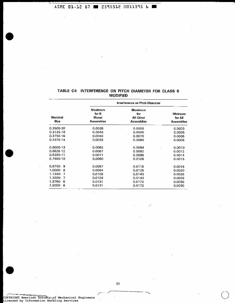
ASME B3.32 87 m 2575532 0033375 b m
TABLE C4 INTERFERENCE ON PITCH DIAMETER FOR CLASS 5 MODIFIED
Interference on Pitch Diameter
Nominal Size
Maximum for K
Monel Assemblies
Maximum for
All Other Assem blies
Minimum for All
Assemblies
0.2 500-20 0.31 25-1 8 0.3750-1 6 0.4375-14
0.0039 0.0045 0.0048 0.0059
0.0055 0.0065 0.0070 0.0080
0.0003 0.0005 0.0006 0.0008
0.5000-1 3 0.5625-1 2 0.6250-1 1 0.7500-10
0.0062 0.0067 0.0071 0.0080
0.0084 0.0092 0.0098 0.0105
0.0010 0.001 2 0.0014 0.001 5
0.8750- 9 0.0087 0.01 16 0.001 8 1.0000- 8 0.0094 0.01 28 0.0020 1.1250- 7 0.0109 0.0143 0.0025 1.2500- 7 0.01 09 0.01 43 0.0025 1.3750- 6 0.0131 0.01 72 0.0030 1.5000- 6 0.0131 0.01 72 0.0030
53 - COPYRIGHT American Society of Mechanical EngineersLicensed by Information Handling ServicesCOPYRIGHT American Society of Mechanical EngineersLicensed by Information Handling Services
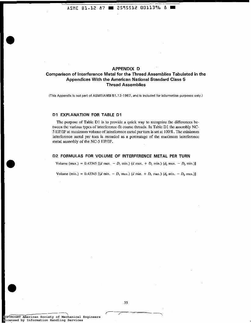
ASME B 1 . 1 2 87 m 2575532 0011376 B m
APPENDIX D Comparison of Interference Metal for the Thread Assemblies Tabulated in the
Appendices With the American National Standard Class 5 Thread Assemblies
(This Appendix is not part of ASME/ANSI B I . 12-1 987, and is included for information purposes only.)
D1 EXPLANATION FOR TABLE D1
The purpose of Table D1 is to provide a quick way to recognize the differences be- tween the various types of interference-fit coarse threads. In Table D1 the assembly NC- 5 HF/IF at maximum volume of interference metal per turn is set at 100%. The minimum interference metal per turn is recorded as a percentage of the maximum interference metal assembly of the NC-5 HFm.
D2 FORMULAS FOR VOLUME OF INTERFERENCE METAL PER TURN
Volume (max.) = 0.45345 [(d max. - DI min.) (d max. + DI min.) (d2 max. - D2 min.)]
Volume (min.) = 0.45345 [(d min. - DI max.) (d min. + DI max.) (d2 min. - 0 2 max.)]
COPYRIGHT American Society of Mechanical EngineersLicensed by Information Handling ServicesCOPYRIGHT American Society of Mechanical EngineersLicensed by Information Handling Services

TAB
LE D
1
THR
EA
D A
SS
EM
BLI
ES
CO
MP
AR
ED
BY
PE
RC
EN
TAG
E O
F IN
TER
FER
EN
CE
ME
TAL
PER
TU
RN
~
~ ~
~~~~
~~~
~ ~
~ ~
Inte
r-
61
.12
A
ppen
dix
A
App
endi
x A
A
ppen
dix
C
App
endi
x C
N
omin
al
feri
ng
BI .
12
C
SFl
lNF
Tent
ativ
e A
ltern
ate
App
endi
x B
A
ppen
dix
C
CS
FKllN
FS
App
endi
x C
C
SFS
llNFS
O
NFS
/INFS
S
ize
Met
al
HF
llF
ON
FlIN
F H
28
H
28
H
FM
/IFM
H
FK/IF
S
ON
FK/IN
FS
HFS
/IFS
1/4-20
Y1 6- I 8
3/s- I
6
'/16-
1 4
v2- 1 3
si1 6- 1 2
vi o\
%-I
1
3/4- I O
7/8-
9
1-8
1 %- 7
1 '/4
- 7
1 3/8- 6
1%-
6
Max
. M
in.
Max
. M
in.
Max
. M
in.
MaF
. M
in.
Max
. M
in.
Max
. M
in.
Max
. M
in.
Max
. M
in.
Max
. M
in.
Max
. M
in.
Max
. M
in.
Max
. M
in.
Max
. M
in.
Max
. M
in.
100.0
3.9
100.0
5.5
100.0
6.2
100.0
7.5
100.0
8.7
100.0
9.7
100.0
10.5
100.0
9.4
100.0
11.5
100.0
11.5
100.0
13.1
100.0
13.1
100.0
12.9
100.0
13.1
100.0
3.9
103.8
5.7
103.5
6.5
127.4
9.4
126.3
11.4
127.9
12.7
130.8
14.4
134.9
15.2
135.6
16.7
136.3
17.1
137.1
19.5
137.2
19.5
135.1
19.2
135.2
19.2
30.0
3.5
57.8
5.2
60.0
4.8
71.3
6.2
74.4
6.9
74.0
7.2
71.2
6.9
73.9
7.5
66.9
7.6
60.3
7.5
53.6
6.7
53.6
7.3
43.9
6.0
47.2
6.5
...
66.4
5.2
69.0
4.8
81.2
7.2
83.9
8.8
81.4
9.9
81.9
10.4
90.5
10.8
76.2
9.8
69.5
8.9
62.7
8.6
62.7
8.5
51.3
7.2
54.6
8.0
21.9
0.0
17.4
0.0
16.0
0.0
21 .o
0.0
25.9
0.0
25.8
0.0
25.7
0.0
24.4
0.0
22.9
0.0
20.9
0.0
18.8
0.0
18.8
0.0
15.8
0.0
15.8
0.0
59.8
3.9
58.1
5.5
57.2
6.2
64.1
7.5
62.3
8.7
61.7
9.7
59.7
10.5
57.1
9.4
62.1
11.5
59.9
11.5
62.7
13.1
62.7
13.1
61.5
12.9
62.1
13.1
59.8
3.9
59.5
5.7
59.6
6.5
78.4
9.4
78.6
11.4
78.1
12.7
80.1
14.4
87.7
15.2
86.2
16.7
85.9
17.1
90.6
19.5
90.7
19.5
88.9
19.2
88.3
19.2
86.6
3.9
87.4
5.5
85.5
6.2
89.9
7.5
87.4
8.7
87.9
9.7
86.9
10.5
78.4
9.4
83.3
11.5
84.8
11.5
85.3
13.1
85.2
13.1
84.0
12.9
84.4
13.1
86.6
3.9
87.9
5.7
89.0
6.5
109.3
9.4
109.4
11.4
110.9
12.7
114.0
14.4
118.7
15.2
119.3
16.7
120.3
17.1
121.7
19.5
121.8
19.5
11 9.6
19.2
119.7
19.2
COPYRIGHT American Society of Mechanical EngineersLicensed by Information Handling ServicesCOPYRIGHT American Society of Mechanical EngineersLicensed by Information Handling Services

L ..... ....... ........ . .... .. I ~ .
ASME Bl.32 87 m 2595532 OOLL378 3 m
1
AMERICAN NATIONAL STANDARDS FOR SCREW THREADS
(Published by The American Society of Mechanical Engineers)
TITLE OF STANDARD
Unified Inch Screw Threads (UN and UNR Thread Form) ................................. B I . 1-1 982
Screw Thread Gaging Systems for Dimensional Acceptability . Inch and Metric Screw Threads (UN, UNR, UNJ, M, and MJ) . . . . . . . . . B I .3 M.1986
Acme Screw Threads ................................................................ B I . 5.1977 Nomenclature, Definitions, and Letter Symbols for Screw Threads ..................... B I .7 M.1984 Stub Acme Screw Threads ........................................................... B I . 8.1977 Buttress Inch Screw Threads 7O145O Form With 0.6 Pitch Basic Height of
Thread Engagement ........................................................ B I . 9.1973(RI 985) Unified Miniature Screw Threads .................................................... B I . 10-1 958 Microscopic Objective Thread ................................................ B I . 11-1 958(R1978) Class 5 Interference-Fit Thread ...................................................... B I . 12-1 987 Metric Screw Threads - M Profile ................................................. B I . 13M-1983 Gages and Gaging for Metric M Screw Threads ...................................... B I . 16M-1984 Metric Screw Threads for Commercial Mechanical
Fasteners - Boundary Profile Defined ............................................ B I . 18M-1982 Gages for Metric Screw Threads for Commercial Mechanical
Fasteners - Boundary Profile Defined ............................................ B I . 19M-1984 Pipe Threads, General Purpose (Inch) Dryseal Pipe Threads (Inch) ................................................ B I .20. 3.1976(RI 982) Dryseal Pipe Threads (Metric Translation of B I .20. 3.1976) . . . . . . . . . . . . . . . . . . . B I .20. 4.1976(RI 982) Gaging for Dryseal Pipe Threads (Inch) .............................................
Hose Coupling Screw Threads ............................................. B I .20. 7.1966(R1 983) Metric Screw Threads - MJ Profile ................................................ B I . 21 M-I 978 Gages and Gaging for MJ Series Metric Screw Threads .............................. B I .22 M.1985
Gages and Gaging for Unified Inch Screw Threads ...................................... B I . 2.1983
.......................................... ... . . B I .20. 1.1983
1
B I .20. 5.1978 Gaging for Dryseal Pipe Threads (Metric Translation
............................................................. of B1.20.5-1978) B1.20.6M-1984 4
The ASME Publications Catalog shows a complete list of all the Standards published b y the Society . The catalog and binders for holding these Standards are available upon request .
~
/-r /-, 7 ~~
COPYRIGHT American Society of Mechanical EngineersLicensed by Information Handling ServicesCOPYRIGHT American Society of Mechanical EngineersLicensed by Information Handling Services


