ASME PTC-8!2!1990_Centrifugal Pump
77
Transcript of ASME PTC-8!2!1990_Centrifugal Pump


Centrifugal Pumps
ASME PTC 8.2-1990
i PERFORMANCE ' i TEST j CODES
T H E A M E R I C A N S O C I E T Y O F M E C H A N I C A L E N G I N E E R S
United Engineering Center 345 East 47th Street New York, N.Y. 1001 7

Date of Issuance: February 15, 1991
This document will be revised when the Society approves the issuance of the next edition, scheduled for 1995. There will be no Addenda issued to PTC 8.2-1990.
Please Note: ASME issues written replies to inquiries concerning interpretation of technical aspects of this document. PTC 8.2-1990 is being issued with an automatic suhscription service to the interpretations that will be issued to it up to the publication of the 1995 edition.
ASME is the registered trademark of The American Society of Mechanical Engineers.
This code or standard was developed under procedures accredited as meeting the criteria for American National Standards. The Consensus Committee that approved the code or standard was balanced to assure that individuals from competent and concerned interests have, had an opportunity to participate. The proposed code or standard was made available for public review and comment which provides an opportunity for additional public input from industry, academia, regulatory agencies, and the public-at-large.
ASME does not "approve," "rate," or "endorse" any item, construction, proprietary device, or activity.
ASME does not take any position with respect to the validity of any patent rights asserted in connection with any items mentioned in this document, and does not undertake to insure anyone utilizing a standard against liability for infringement of any applicable Letters Patent, nor assume any such liability. Users of a code or standard are expressly advised that determination of the validity of any such patent rights, and the risk of infringement of such rights, is entirely their own responsibility.
Participation by federal agency representative(s) or person(s) affiliated with industry is not to be interpreted as government or industry endorsement of this code or standard,
ASME accepts responsibility for only those interpretations issued in accordance with governing ASME procedures and policies which preclude the issuance of interpretations by individual vol- unteers.
No part of this document may be reproduced in any form, in an electronic retrieval system or otherwise,
without the prior written permission of the publisher.
Copyright Q 1991 by THE AMERICAN SOCIETY OF MECHANICAL ENGINEERS
All Rights Reserved Printed in the U.S.A.

FOREWORD
(This Foreword is not part of ASME/ANSI PTC 8.2-1990.)
In 1952, the Power Test Code Committee organized a subcommittee under PTC Committee No. 8 on Centrifugal Pumps with instructions to prepare a test code applicable to a broad range of centrifugal pumps. Superseding PTC 8.1 -1 954, the new Code, PTC 8.2, was approved and adopted by the Society in August 1965. It was revised by addendum in 1973.
In 1974, the revised Code was submitted to the American National Standards Institute (ANSI) for acceptance as an ANSI Standard. By spring of 1977, concensus had not been achieved. While this did not invalidate existing PTC 8.2, ASME concluded that PTC 8.2 might better satisfy current industry needs and achieve broader acceptance through review and update.
Through 1977 a committee was formed with select membership from a broad spectrum of the pump industry. Initial work on the new code began in December of 1977. This Code achieved preliminary acceptance by the ASME Board on Performance Test Codes in July 1987. Final detail issues were resolved and the Code approved for publication on March 21, 1990.
This Code supersedes ASME Performance Test Code 8.2-1965 along with its 1973 Addendum.
iii
All ASME codes are copyrighted, with all rights reserved to the Society. Reproduction of this or any other ASME code is a violation of Federal Law. Legalities aside, the user should appreciate that the publishing of the high quality codes that have typified ASME documents requires a substantial commitment by the Society. Thousands of volunteers work diligently to develop these codes. They participate on their own or with a sponsor's assistance and produce documents that meet the requirements of an ASME consensus standard. The codes are very valuable pieces of literature to industry and commerce, and the effort to improve these "living documents" and develop additional needed codes must be continued. The monies spent for research and further code development, administrative staff support and publication are essential and constitute a substantial drain on ASME. The purchase price of these documents helps offset these costs. User reproduction undermines this system and represents an added financial drain on ASME. When extra copies are needed, you are requested to call or write the ASME Order Department, 22 Law Drive, Box 2300, Fairfield, New Jersey 07007-2300, and ASME will expedite delivery of such copies to you by return mail. Please instruct your people to buy required test codes rather than copy them. Your cooperation in this matter is greatly appreciated.
IV

PERSONNEL OF PERFORMANCE TEST CODES COMMITTEE NO. 8.2 ON CENTRIFUGAL PUMPS
(The following is the roster of the committee at the time of approval of this Code.]
OFFICERS R. J. Biese, Chairman
W. L. Dornaus, Vice Chairman G. Osolsobe, Secretary
COMMITTEE PERSONNEL R. J. Biese, Gilbert/Commonwealth Inc. L. W. Boyd, Tennessee Valley Authority J. J. Brunner, Bechtel Power Corp. W. L. Dornaus, Consultant (past Chairman) C. A. Eubanks, Westinghouse Electric Corp. J. W. Leavitt, CE-KSB Pump Co. F. J. Monaghan, Public Service Electric & Gas Research Corp. J. S. Robertson, US. Army Corps of Engineers (retired) J. W. Umstead, Duke Power Co. R. J. Walker, Consultant
Acknowledgments
The PTC 8.2 Committee wishes to acknowledge the contribution of the following individuals:
A. J. Acosta, California Institute of Technology F. W. Buse, Ingersoll-Rand Inc. J. L. Dicrnas, Consultant W. A. Ellwood, American Electric Power Service Corp. C. S. Goolsby, Duke Power Co. R. Johansen, Duke Power Co. W. L. Krutzsch, Worthington Pump Co. K. O'DOflflell, Goulds Pumps K. L. Peterson, Byron Jackson Pump Division P. Schaub, Potomac Electric Power Co.
V

BOARD ON PERFORMANCE TEST CODES PERSONNEL
J. S. Davis, Jr., Vice President R. Jorgensen, Vice Chairman
W. 0. Hays, Secretary
A. F. Armor R. L. Bannister J. A. Booth B. Bornstein W. A. Crandall H. G. Crim J. S. Davis N. R. Deming
W. L. Garvin G. J. Gerber R. Jorgensen D. R. Keyser J. E. Kirkland W. G. McLean J. W. Murdock S. P. Nuspl
R. P. Perkins R. W. Perry A. L. Plumley J. A. Reynolds C. B. Scharp J. W. Siegmund R. E. Sommerlad J. C. Westcott
vi

CONTENTS
... Foreword ................................................................................ 111
Committee Roster ..................................................................... V
. . 1 Object and Scope ............................................................. 1 2 Terms. Definitions. Symbols. and Units ...................................... 5 3 Guiding Principles .............................................................. 11 4 Instruments and Method of Measurement ................................... 15 5 Computation of Results ........................................................ 37 6 Report of Test .................................................................. 41
Figures 2.2 Datum Location for Typical Pump Types ..................................... 4.7.1 Typical Pressure Tap Connections ............................................
Pu In p .........................................................................
Suction Pump ................................................................
Measurements of Head Using Gages or Manometers ...................... 4.7.5 Ring Manifold on Suction Using a Gage ...................................... 4.7.6 Ring Manifold on Discharge Using a Gage ...................................
4.7.8 Single Tap on Suction and Discharge Nozzles ............................... 4.7.9 Single Tap on Discharge Using a Manometer ................................ 4.7.1 0 Single Tap on Suction Using a Manometer ................................... 4.1 2.1 A Typical Air or Water Purge System ......................................... 4.12.2 A Typical Seal With Intermittent Purge ....................................... 4.40.1 NPSH Test Arrangement ...................................................... 4.40.2 NPSH Test Arrangement ...................................................... 4.40.3 NPSH Test Arrangement ...................................................... 4.40.4 NPSH Test Arrangement ...................................................... 4.43.1 Constant Capacity ............................................................. 4.43.2 Constant Capacity ............................................................. 4.43.3 Constant Capacity ............................................................. 4.44.1 Constant NPSH ................................................................ 4.44.2 Constant NPSH ................................................................ 5.7.1 .................................................................................. 5.7.2 .................................................................................. 5.7.3 .................................................................................. 5.7.4 .................................................................................. 5.7.5 ..................................................................................
4.7.2 Typical Pressure Tap Arrangement for an Open-Pit Vertical
4.7.3 Typical Pressure Tap Arrangement for a Vertical Canned
4.7.4 Typical Piezometer Ring Manifold Arrangements for
4.7.7 Typical Piezometer Ring Manifold Arrangement for Measurement of Head Using a Differential Manometer ...................
8 16
18
19
20 21 21
22 23 24 24 26 27 30 30 31 32 33 33 33 34 34 38 38 38 38 38
vii

Tables 1 .I I Acceptable Instrument Accuracies. Flow Uncertainty. and
4.22 Classification of Fluid Meters and Methods of Fluid Fluctuation of Readings ...................................................... Measurement ................................................................
Appendices A Summary of Agreements by the Parties to the Test ........................... B Test Criteria Locator for Type A and Type B Tests ................ *. .......... C Uncertainty Analysis Example .................................................. D Cavitation ....................................................................... E Model Testing .................................................................. F Effect of Suction-Side Hydraulics .............................................. G Conversion to SI (Metric) Units ............................................... H Additional Guidance on NPSH Testing ........................................
Figures
H2.2 Typical Examples of NPSH Test Run Results .................................. H2.3 NPSHR at Break-off and Alternate Head Reductions .......................... H3 NPSH Test Results for Constant NPSH Values ................................
H2.1 General NPSH Vs . Head Performance (Constant Capacity) ..................
Table . Cl Uncertainty Summary Table ...................................................
3
25
43 45 47 57 61 65 67 69
70 71 72 73
49
Complete Listing of ASME Performance Test Codes .......................... 75
viii

ASME PTC 8.2-1990
SECTION 1 OBJECT AND SCOPE
1.1 Prepared in accordance with ASME PTC 1 on General Instructions, this Code provides standard di- rections for conducting and reporting performance tests of centrifugal pumps, including those of the mixed flow and axial flow types, hereinafter inclu- sively covered by the term “pumps.”
1.2 The objective of this Code is to establish rules for conducting tests of pumps to determine, under specified conditions, the following characteristics:
(a) total head produced by the pump; (6) pump capacity (rate of flow through the
(c) power input to the pump; (dl efficiency; (e) net positive suction head requirements of the
pump. The above characteristics are hereinafter inclu-
sively covered by the term “performance.” In addition to the foregoing, this Code provides
nonmandatory appendices which provide additional guidance related to the application of this Code.
pump);
1.3 This Code applies to the testing of pumps utiliz- ing liquids or mixtures of miscible liquids which have Newtonian viscosity characteristics.
1.4 If specific directions in this Code for any partic- ular measurement differ from those given in a refer- ence code for similar measurements, the instructions of this Code shall prevail. It is the intent of this Code that the meaning of all terms be understood and ap- plied as defined in Section 2 of this Code.
1.5 This Code mandates testing procedures and ac- ceptable instrumentation for tests designated Type A and Type B. Subsequent reference in this Code will be made to these as Type A and Type B (see Section 3). Prior to the test, the parties to the test must agree
in writing to the type of test to.be conducted. If this Code is invoked without reference to type, the test shall be conducted in accordance with criteria estab- lished for Type A.
Tests may be designated as “single” or “mixed” type tests.
(a) Single-type tests are conducted when proce- dures and instrumentation from only one type are specified.
(6) The user of this Code may wish to reduce some aspects of the Type A test to Type B. Procedures spec- ified from both types render the test designation as Type B. Upgrading some Type B criteria to Type A is also permissible but again the resultant designation shall be Type. B. Any such tests shall be agreed in writing by the parties to the test.
Only tests which comply with, and do not exclude or violate the mandatory requirements of, this Code may be designated as tests conducted in accordance with this Performance Test Code. Characteristics (a) through (d), inclusive, of para. 1.2 shall be deter- mined for both Type A and Type B tests.
1.6 Instruments and methods of measurement to satisfy Type A, Type 8, or mixed-type tests are given in Section 4 of this Code. Descriptions of instruments and apparatus beyond those specified, but necessary to the conduct of tests under this Code, may be found in the ASME Performance Test Code Supplements on Instruments and Apparatus (PTC 19 Series). If specific directions in this Code for any particular measure- ment differ from those given in the PTC 19 Series, the instructions in this Code shall prevail.
1.7 The tests specified in this Code may be con- ducted in the manufacturer’s shops, on the user’s premises or elsewhere as agreed upon, provided such tests meet the requirements of this Code.
1.8 Results of tests conducted in accordance with this Code apply solely to the specific pump actually
1

ASME PTC 8.2-1990 CENTRIFUGAL PUMPS
tested. The measured test data refer only to the pump test system. The record of the test and the final test report may include information on the composite unit, including driving and auxiliary equipment.
1.9 Tests of model pumps and/or substitute liquids, if in conformance with all mandatory sections of this Code, may be reported as tests conducted in accord- ance with this Code but, as specified in para. 1.6 of this Code, pertain solely to that liquid and pump. Results extrapolated from tests of model pumps and/ or substitute liquids and presented as another pump’s performance in meeting guarantees, are outside the scope of this Code. Although the method of extrap- olation of the results to predict another pump’s per- formance may be agreed upon by the parties to the test, such extrapolated results shall not be designated results of a test conducted in accordance with this Code [see para. 3.4(b) and (g) and Appendix El.
1.10 Reference by this Code to other codes or stan- dards shall be interpreted to impose the referenced code or standard in effect at the time the agreement to conduct the test is made by the parties to the test.
1.11 Test results adjusted for speeds outside the range noted in Table 1 .I 1 are outside the Scope of this Code. Tests shall be conducted at the specified
test speed within the criteria established by Table 1.11.
1.12 Measurement Uncertainty. By satisfying the instrument accuracy criteria in Table 1 .I 1, and the balance of the procedural requirements of this Code, Types A and B testing will generally provide 95% or greater confidence that the measurement of the tested parameters identified in Table 1.11 will yield results for which the bounds of the differences be- tween the reported test results and the true values are closely approximated as follows:
Type A Discharge head ? 0.44% 2 1.89% Suction head ?0.91% f 3.99% Total head [Note (1 ) I f 0.45% 21.91% Efficiency t l . 3 3 % t2.45% Capacity ?0.81% 22.12%
Using PTC 19.1, the foregoing values are based on significant typical experience and precision indices for that experience. They are given in this Code as generic values which closely approximate the bound- ing values for type A and B tests. If specific test values are required for the overall test, PTC 19.1 shall be utilized to determine the specific test uncertainty. This shall be done only by agreement of the parties to the test. Appendix C of this Code provides an ex- ample of the use of PTC 19.1 for pump test uncer- tainty analysis.
2

CENTRIFUGAL PUMPS ASME PTC 8.2-1990
TABLE 1.1 1 ACCEPTABLE INSTRUMENT ACCURACIES, FLOW UNCERTAINTY, AND FLUCTUATION OF READINGS (See paras. 3.8, 3.9, and 4.4)
Allowable Fluctuations Acceptable Measurement of Test Instrument
[Notes (2) and (3)l
Test Quantities Uncertainty U Type A Type B Type A Type
Total Pump Head, H . . . . . . . . . f 2% -c4% [Note (4)l Total Discharge Head, Hd A f 0.25% f 0.5% 2 2% rt 4% Total Suction Head, H. A f 0.25% 20.5% f 3% f 6% Capacity, Q [Note (5)l U +- 0.75% f 2.0% 5 2% f 4% Pump Speed, n A f O . 1 % f 0.5% 2 0.3% +0.75% Pump Power Input, BHP A & 1 .O% f 2.0% * 1 .O% 52.0%
NOTES:
Accuracy A AccuracyhJncertainty Readings
or [Note (111
~~
A speed variation from that specified for test is allowed within the following ranges: Type A k 3%, Type B f 5%. Allowable fluctuations are applicable within 2 10% of peak efficiency under noncavitating con- ditions. See para. 4.4. The table presumes that total pump head is computed as the algebraic difference between dis- charge and suction heads. If total pump head is measured directly, the criteria for Type A and B tests for total suction and total discharge heads apply. This is total measurement uncertainty, including differential measurement, temperature meas- urement, and element calibration. For an example of computation methodology to satisfy the criteria established in this table, refer to PTC 19.1 on Measurement Uncertainty. The Type B test assumes an uncalibrated nozzle.
3

CENTRIFUGAL PUMPS ASME PTC 8.2-1990
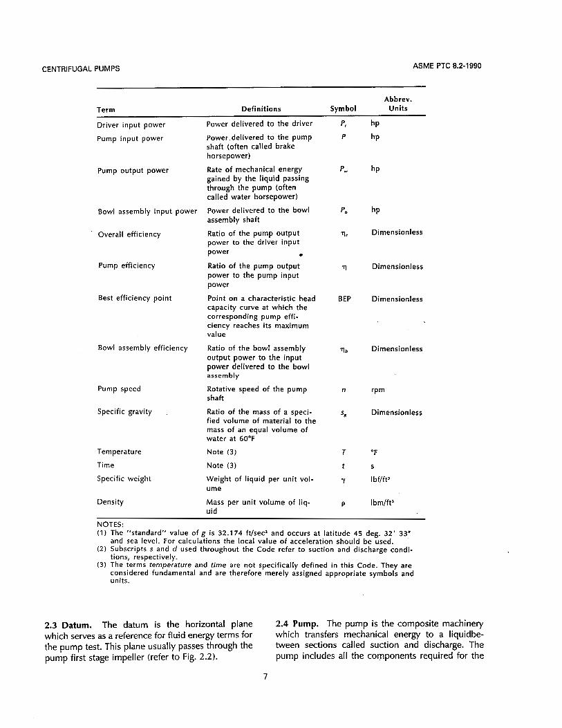
SECTION 2 - TERMS, DEFINITIONS, SYMBOLS, AND UNITS
2.1 System of Units. The U.S. customary system of units i s the system selected for this Code.
Term Force Mass Length Time Gravity Standard
Symbol F M L t g = 7 ma
Pound Pound (pound mass) (foot) Units Force Mass Foot Second (pound force) (secondz)
32.1 74
Units I bf Ibm ft S Abbrev.
(Ibm) (ft)/(lbf) (sz)
2.2 Terms and Definitions. The terms, definitions, symbols, and units are listed below
Term Abbrev.
Definitions Symbol Units
Pump capacity
Area
Mean velocity
Gage pressure
Absolute pressure
Gravity
Head
Volume rate of flow delivered by the pump
Flow cross section
Flow rate divided by the cross-sectional area at the point of measurement
The measure of the cumula- tive static and dynamic force exerted by or on a liquid per unit area, exclusive of atmos- pheric influence
The measure of the cumula- tive static and dynamic force exerted by or on a liquid per unit area, inclusive of atmos- pheric influence
Acceleration due to gravity INote ( ? ) I The term used to express the mechanical energy content of the liquid referred to an arbi- trary datum. In terms of en- ergy, all head terms have the dimension ft.
5
Q ft’ls gal/min
A f t 2
V ft/s
P S Ibf/in2
P. Ibf/in.2
g ft/s2
No symbol f t

ASME PTC 8.2-1990 CENTRIFUGAL PUMPS
Term Abbrev.
Definitions Symbol Units
Total pump head [Note (2)] The algebraic difference be- tween the total discharge head and the total suction head
Total discharge head The algebraic sum of the [Note (2)l pressure head, the elevation
head and the velocity head at the pump discharge referred to datum (see Fig. 2.2)
Total suction head [Note (2)l
Pressure head
Elevation head
Velocity head
Vapor pressure head
The algebraic sum of the pressure head, the elevation head and the velocity head at the pump suction referred to -datum (see Fig. 2.2)
Head of liquid equivalent to the gage preshre. This term may be positive (called “head”) or negative (called “lift”) when referred to the pump datum (see Fig. 2.2)
Vertical distance from datum. Can be either positive (above datum) or negative (below datum) (see Fig. 2.2 and Figs. 5.7.1 through 5.7.5)
Kinetic energy of fluid per unit mass at the point of measurement (see para. 2.7)
Vapor pressure of the fluid at the pumping temperature ex- pressed as head of l iquid being pumped during the test
Net positive suction head Total suction head plus baro- metric head, less the vapor pressure head of the liquid
Net positive suction head NPSH available to the pump available referenced to datum (see Fig.
2.2)
H f t
H,, f t
H, ft
H, f t
H, f t
H, f t
H, ft
NPSH f t
NPSHA ft
Net positive suction head The NPSH of .a pump at any NPSHR ft required discrete capacity and associ-
ated speed at which the per- formance begins to deteriorate
Barometric head Atmospheric pressure ex- Ha, ft press.ed i n feet of l iquid
Total bowl assembly head Algebraic sum of the pressure H, f t head, the elevation head and the velocity head determined at the gage connection, plus the losses in equipment be- tween the bowl assembly and the point at which the pres- sure is measured
Torque The turning moment about 7 Ib-ft or Ib-in. the axis of a power transmit- t ing shaft
6
CENTRIFUGAL PUMPS ASME PTC 8.2-1990
Abbrev. Term Definitions Symbol Units
Driver input power
Pump input power
Pump output power
Bowl assembly input power
Overall efficiency
Pump efficiency
Best efficiency point
Bowl assembly efficiency
Pump speed
Specific gravity .
Temperature
Time
Specific weight
Density
power delivered to the driver
Power delivered to the pump shaft (often called brake horsepower)
Rate of mechanical energy gained by the liquid passing through the pump (often called water horsepower)
power delivered to the bowl assembly shaft
Ratio of the pump output power to the driver input power 0
Ratio of the pump output power to the pump input power
Point on a characteristic head capacity curve at which the corresponding pump effi- ciency reaches i t s maximum value
Ratio of the bowl assembly output power to the input power delivered to the bowl assembly
Rotative speed of the pump shaft
Ratio of the mass of a speci- fied volume of material to the mass of an equal volume of water at 60°F
Note (3)
Note ( 3 )
Weight of liquid per unit vol- ume
Mass per unit volume of liq- uid
p i
P
Pw
' b
I l t
11
BEP
? b
n
ss
T
t
Y
P
hP
Dimensionless
Dimensionless
Dimensionless
Dimensionless
rPm
Dimensionless
"F
S
Ibf/ft3
Ibm/ft3
NOTES: (1) The "standard" value of g i s 32.174 ft/sec2 and occurs at latitude 45 deg. 32' 33"
and sea level. For calculations the local value of acceleration should be used. (2) Subscripts s and d used throughout the Code refer to suction and discharge condi-
( 3 ) The terms temperature and time are not specifically defined in this Code. They are tions, respectively.
considered fundamental and are therefore merely assigned appropriate symbols and units.
2.3 Datum. The datum is the horizontal plane which serves as a reference for fluid energy terms for the pump test. This plane usually passes through the pump first stage impeller (refer to Fig. 2.2).
2.4 Pump. The pump is the composite machinery which transfers mechanical energy to a liquidbe- tween sections called suction and discharge. The pump includes all the components required for the
7

ASME PTC 8.2-1990 CENTRIFUGAL PUMPS
Horizontal Centrifugal
Datum
Datum
Inclined "\. Axial Flow
Horizontal Double Suction Centrifugal
Horizontal Axial Flow
Vertical Axial Flow
43
I
Datum
Vertical Double Vertical Centrifugal Suction Centrifugal
Vertical Mixed Flow
Vertical Centrifugal Enclosed Impeller
FIG. 2.2 DATUM LOCATION FOR TYPICAL PUMP TYPES
8

CENTRIFUGAL PUMPS ASME PTC 8.2-1990
transfer of pump input power to the liquid. Unless integrally attached to the pump, the driver is not part of the pump (refer to para. 3.3). In the case of a vertical diffuser type pump, the pump includes the discharge head or elbow, column pipe and shafting.
2.5 Bowl Assembly. The bowl assembly is that por- tion of a vertical diffuser type pump which is below the discharge column and/or discharge head, usually . consisting of the suction bell, impeller(s), diffuser(s), and the section of shafting contained therein. The assembly may include a single bowl or multiple bowls, and is so defined as to allow its testing under this Code, since such tests are commonly required for this type of pump.
2.6 Velocity Head. The velocity head is specifically defined by the expression
V Z H, = -
2g
The velocity head shall be calculated by using a mean velocity computed as the ratio of the volume rate of flow to the pipe area, both determined at the measuring section. When the velocity head at the measuring section is computed to be greater than 5% of the total head produced by the pump, the velocity head shall be determined by Pitot tube traverses. In this event, the velocity head shall be determined by
two or more Pitot tube traverses. The angular dis- placement between the traverses shall be 180 deg. divided by the number of traverses.
2.7 If a liquid resists shear in linear proportion to the time rate of shear, the liquid is referred to as "Newtonian." Only liquids of Newtonian viscosity characteristics are covered by this Code.
2.8 Cavitation.' Cavitation is a condition in which vapor bubbles formed by local dynamic pressure re- duction in a flow stream, collapse or implode when carried into a region of higher pressure exceeding the vapor pressure of the liquid. Cavitation is generally detected by observation of a change in head and/or horsepower. Increases in noise and vibration are also associated with cavitation.
2.9 Testing Nomenclature
(a) A reading is a measurement of a test parameter. (b) A test point is a set of readings that describe
performance characteristics at a specific operating condition.
(c) A test run is a set of test points. (d) A test report is the formal compilation and doc-
umentation of results in accordance with Sections 5 and 6 of this Code.
9

CENTRIFUGAL PUMPS ASME PTC 8.2-1990
SECTION 3 - GUIDING PRINCIPLES
3.1 As stated in Section 1, this Code includes two types of tests. The purpose of the two classifications is to provide a Code which offers options to those who apply the Code, so that an appropriate level of precision and uncertainty can be selected without compromising the technical requirements of the ap- plication.
3.2 The selection of the test type specified should be made carefully after a thorough study of the Code and options available within it.
3.3 The determination of what is to be tested as the “pump” is not always clear. In most cases, the con- figuration of the machine normally called the pump fits the Code definition with no potential for confu- sion. However, there are many special cases in which the pump is not simply identified. It is encumbent on the parties to the test to reach written agreement concerning the envelope of equipment which is to be identified as the pump, carefully specifying what sec- tions are to be identified as suction and discharge. In cases where bleed or injection flows are encoun- tered, the method of assessment of these flows as they affect performance should be agreed upon in writing prior to the test.
TYPE A TYPE B
3.4A Items on which agreement shall be reached 3.4B The test facility shall establish the liquid, test prior to conducting the tests are: location, test personnel, driver, instrumentation and
(a) pump to be tested (refer to paras. 1.8 and 1.9); test stand configuration. NPSH testing per require- (b) whether or not NPSH testing per requirements ments of paras. 4.38 through 4.44 may be added to
of paras. 4.38 through 4.44 will be included; Type B tests by written agreement of parties to the (c) test liquid and its properties; test. (d) location of test; (e) instrumentation and test personnel to be pro-
vided and by whom;
11

ASME PTC 8.2-1990 CENTRIFUGAL PUMPS
(0 test setup and procedures to be used; (@ driver to be used (see paras. 4.32 through
4.34).
3.5A Documentary evidence of current calibrations shall be available for review, prior to the test, for all instruments usgd in determining the pump hydraulic and mechanical performance (see para. 4.45).
3.6A The test shall not start until steady state con- ditions have been established to assure proper op- eration of pump and test equipment, and a correct routine of observations has been established.
3.7A Accumulation of test data shall begin only when steady test conditions have been established and fluc- tuations are within the limits of Table 1 .I 1.
3.8A Five or more readings shall be taken and re- 3.8B One reading shall be taken at each test point. corded at equal time intervals for each test point. The Test results shall be computed after the test in ac- result shall be the average of the readings. Test results cordance with the directions given in Section 5 and shall be computed during or immediately after the shall be kept on record. A performance curve shall test in accordance with the directions given in Section be furnished. A report shall be furnished in accord- 5. Complete records of all information and results ance with the directions given in Section 6.
given in Section 6. shall be furnished in accordance with the directions
3.9A The test shall include a sufficient number of points, but not fewer than 10, to accurately define the head-capacity curve over the range from mini- mum to maximum capacity. Within this range, test points shall be selected such that the increment in capacity between adjacent points does not exceed 10% of the specified capacity, and at least one of the test points shall be within +2% of the specified ca- pacity, or 2 2 % of the specified head. The increment between shut-off and the lowest test capacity may be 15% of the specified capacity. Testing at shut-off or at capacities below 25% of BEP shall be done only by agreement by the parties to the test.
3.9B The test shall include a minimum of eight test points between 25% of specified capacity and the maximum test capacity, which shall be at least 105% of specified capacity, or as otherwise agreed by the parties to the test. At least one point shall be with ? 3% of the specified capacity, or t 3% of the spec- ified. head, and no increment in capacity between ad- jacent points shall exceed 15% of the specified capacity. Testing at shut-off or at capacities below 25% of BEP shall be done only by agreement by the parties to the test.
3.1 OA In accordance with PTC 1 , tests conducted un- der this Code may be used to compare performance of a pump with specified values of capacity, head, efficiency and NPSH.
12

CENTRIFUGAL PUMPS ASME PTC 8.2-1990
3.11A The test arrangement shall be free from hy- draulic conditions which adversely affect pump per- formance. This is especially important for high capacity, low-head pumps or pumps that will operate in a sump with limited submergence (see Appendix F). NPSHA shall be greater than predicted NPSHR at all test flow rates during the test except during NPSH testing. On tests where the velocity head is greater than 5% of the total head, two or more pitot traverses may be required for accurate determination of aver- age velocity head. The angular displacement between the traverses shall be 180 deg. divided by the number of traverses. This should be agreed upon by the par- ties to the test, prior to the test, including the type of test apparatus.
3.12A The NPSH required by the pump shall be de- termined in accordance with the procedures de- scribed in Section 4 of this Code. NPSH tests shall be made at a specified capacity for the pump, and at the minimum and maximum operating flows, or more capacities as specified. NPSH tests shall be con- ducted only when agreed upon in advance by parties to the test (see paras. 4.38 through 4.44).
3.13A If physical limitations prevent testing with full number of stages or other parameters, the parties to the test may agree upon altered conditions. The al- terations shall be as few as possible to permit testing. The results shall then be computed as directed in Section 5 (see paras. 1.8 and 1.9).
3.12B The NPSH required by the pump shall be de- termined in accordance with the procedures de- scribed in Section 4 of this Code. It shall be determined for one specific condition. Unless oth- erwise agreed by the parties to the test, the NPSH test shall be conducted at the pump runout condition. NPSH tests shall be conducted when agreed upon in advance by parties to the test.
3.136 When a complete pump cannot be tested, the method of accounting for losses attributable to the omitted parts shall be agreed upon prior to the test.
3.14A In the event that a complete vertical diffuser 3.14B Vertical diffuser pump bowl assemblies may pump cannot be tested due to depth limitations im- be tested with test facility column and discharge el- posed by the test facility, sections of column and bow (see para. 3.43B). shaft may be removed to permit maximum length required for proper submergence while testing. The method of accounting for column and shaft losses shall be agreed upon by the parties prior to the test.
3.1 5A During the test, the test fluid temperature var- iation shall not exceed 30°F.
3.16A Test fluid temperature variation shall not ex- 3.16B A test fluid temperature variation limitation ceed 2°F at each test point. will not be imposed at any test point (see paras. 1.8
and 1.9).
13

CENTRIFUGAL PUMPS ASME PTC 8.2-1990
SECTION 4 - INSTRUMENTS AND METHOD OF MEASUREMENT
4.1 This Section presents detailed information on in- struments and methods of measurement to be used in testing pumps.
4.2 In testing, it is generally necessary to measure (a) pressure (suction, discharge, barometric) (6) temperature (liquid and ambient) (c) volume rate of flow (pump capacity) (d) pump speed (e) pump input power In addition, by agreement of the parties to the test,
it may be necessary to determine the following test liquid properties: (0 specific weight or specific gravity (@ viscosity (h) vapor pressure
4.3 Instruments and, indicating devices acceptable for these tests are given in the following list. It must be demonstrated by the test facility that instrumen- tation is suitable for the test and can produce the required levels of accuracy and precision for the type test specified. Refer to the appropriate documents identified below.
(a) PTC 19.2: Barometers, gages, manometers, transducers, or other pressure measuring devices
(b) PTC 19.3: Thermometers, thermocouples, or other thermal measuring devices
(c) PTC 19.5: Flow nozzles, venturi tubes, orifice plates, pitot tubes, elbow meters, turbine me- ters,volumetric meters, or other flow measuring de- vices
(d, Fluid Meters, Their Theory and Application: Magnetic flow meters, rotameters, weight and volu- metric tanks, sonic meters, or other similar devices
(e) PTC 19.6 and PTC 19.22: Electrical and elec- tronic instruments and computerized data acquisition equipment (0 PTC 19.7: Dynamometers, torque meters (@ Calibrated motors: See paras. 4.32 and 4.33 (h) PTC 19.12: Time measuring devices
(i) PTC 19.1 3: Tachometers, revolution counters or
Q PTC 19.16: Density and specific gravity mea-
(k) PTC 19.1 7: Viscosity measuring devices
other speed counting devices
suring devices
4.4 When fluctuations in a measured variable exceed those listed in Table 1 .I 1, it may be necessary to use damping techniques to extract the true signal from the signal-and-noise combination. Damping tech- niques fall into three categories:
(a) the application of mechanical devices such as throttling valves and volume chambers;
(b) the use of electrical circuits such as resistance- capacitance-inductance networks;
(c) the application of mathematical signal averag- ing techniques.
Any of these is acceptable, provided that the output of the device gives a true average output and that i t s response time is fast enough not to mask changes in the measured variable.
PRESSURE MEASUREMENT 4.5 The measurement of pressure for the determi- nation of head is carried out by pressure-indicating devices (gages, manometers, transducers) connected to the liquid passage through pressure taps, or through pressure transmitters which are in turn con- nected to the liquid passage through pressure taps.
4.6 Steady flow conditions shall exist at the gage connection(s) and pressure tap(s). Table 1 .I 1 shows the limits below which fluctuations may be disre- garded and steady flow conditions presumed to exist.
4.7 Pressure taps (see Fig. 4.7.1) shall be placed in sections of constant diameter, concentric with the suction and discharge nozzles . They shall be located a minimum of two pipe diameters upstream from the pump suction flange, and a minimum of two pipe
15

ASME PTC 8.2-1990 CENTRIFUGAL PUMPS
Note contour of plug to match pipe
D / 4 max. radius (or chamfer)
Noncorrosive Plug
Ground smooth
GENERAL NOTES: ( 1 ) 1/8 in. < D < 1 / 4 in. (2) For small bore pipe (less than 1-1/4 in. ID),
D shall not exceed 1 /10 of the inside diameter of the pipe.
FIG. 4.7.1 TYPICAL PRESSURE TAP CONNECTIONS
16

CENTRIFUGAL PUMPS
diameters downstream from the pump. discharge flange. .
For pumps which includeea pipe elbow or other disturbance upstream from the pressure tap connec- tion, such as Figs. 4.7.2 and 4.7.3, it is necessary to locate the pressure tap sufficient distance away from the disturbance to assure a uniform flow profile. Five diameters of straight pipe upstream of the pressure tap is the minimum distance for pressure tap location after a single disturbance. An eccentric reducer con- nected to either the pump suction or discharge noz- zle is considered a "disturbance" when tests are conducted in accordance with this Code.
For Type A tests, where multiple pipe bends or disturbances exist within five diameters upstream of the pressure taps, velocity profile traverses shall be made within one diameter of the tap location and shall be used to adjust the readings by methods agreed upon by the parties to the test. For Type B tests, a five diameter minimum is imposed but the velocity traverse is not required.
For bowl assembly tests, the pressure tap in the column pipe shall be located two diameters of straight pipe downstream from the bowl or concen- tric reducer (see Fig. 4.7.2).
4.7.1 The number of pressure taps will depend on the type of test. For Type A, four static pressure taps shall be provided equally spaced about the periphery of the pipe at the suction and discharge measuring sections. The pressure at'the section is to be taken as the average of these four separate readings.
If any of the four readings differ by more than 1% from the average, the cause should be found and the discrepancy corrected, if possible. The four pressure tap readings need not be measured separately for each test data point (need only be demonstrated once). The four taps shall be connected through nor- mally open shut-off valves to a piezometer ring man- ifold (see Figs. 4.7.4 through 4.7.7) of cross-sectional area not less than the sum of the cross-sectional areas of the taps. '
This ring arrangement makes it possible to deter- mine the pressures at each tap separately by closing the shut-off valves leading to the other three taps. A vent valve shall be placed at the high point of the ring and a drain valve at the low point.
As an alternative to this arrangement, separate gages or manometers shall be provided for each tap.
4.7.2 For Type 8, a single suction and a single dis- charge tap may be used (see Figs. 4.7.2, 4.7.3, and 4.7.8 through 4.7.10).
17
ASME PTC 8.2-1990
4.8 Pressure taps in the pipe shall be flush with and normal to the wall of the liquid passage. For a dis- tance of 6 in. or 25% internal pipe diameter, which- ever is greater, up and downstream of the measuring section, all roughness shall be removed that is greater than the general internal condition of the pipe. The edges of the openings shall be tangent to the wall of the liquid passage and shall be free of burrs or irreg- ularities.
Figure 4.7.1 shows four pressure tap designs in conformity with the above.
4.9 Permissible exceptions to the procedure speci- fied in para. 4.7.1 shall be on metering devices, such as venturi meters, where proper calibrations have been made, or when using a dry-tube type manom- eter, as specified in para. 4.10.
4.10 The instrument lines from the pressure taps to the manometers and gages shall be as short and di- rect as practical to avoid objectionably slow re- sponse. These lines shall be at least 1/8 in. larger in diameter than the piezometer openings, but not less than 1/4 in. inside diameter. For the wet-tube type of lines, vent valves shall be provided at any high point or loop crest to assure that instrument lines do not contain any air or gas. Where conditions prevent the use of wet-tube type lines, dry-tube lines must be used. One or more dry-type pressure taps may be used. For dry-type taps, transparent lines must be used to provide visual assurance that no liquid exists in the line.
4.1 1 All instrument lines, piping and fittings shall be checked under pressure prior to taking test readings to assure that there are no leaks. All lines between pressure taps and measuring instruments shall be vented prior to the test. Liquid-filled lines should slope upward continuously from the instrument to the tap. If this is not possible, the high points must be vented, to eliminate gas pockets. Gas-filled lines should slope downward to automatically drain any liquid. If this is not possible, the low points must be drained to prevent the collection of liquid. A slope of not less than one inch per foot in horizontal lines from pressure tap to instrument is acceptable.
4.12 In applications with corrosive or hazardous fluids, complex mixtures, flocculent or dirty fluids, a limited or continuous fluid purge (of inert gas or
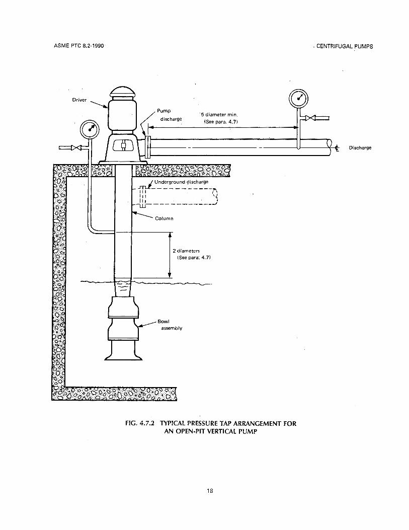
ASME PTC 8.2-1990
Column
t
i 2 diameters (See para. 4.7)
G
- CENTRIFUGAL PUMPS
Discharge
FIG. 4.7.2 TYPICAL PRESSURE TAP ARRANGEMENT FOR AN OPEN-PIT VERTICAL PUMP
18

CENTRIFUGAL PUMPS
R- Driver
Suction
FIG. 4.7.3 TYPICAL PRESSURE TAP ARRANGEMENT FOR A VERTICAL CANNED SUCTION PUMP
ASME PTC 8.2-1990
NOTE? (1) See para. 4.7
19

ASME PTC 8.2-1990 CENTRIFUGAL PUMPS
(1 ) See para. 4.7 for pipe dimensions.
FIG. 4.7.4 TYPICAL PIEZOMETER RING MANIFOLD ARRANGEMENTS FOR MEASUREMENTS OF HEAD USING GAGES OR MANOMETERS
20

CENTRIFUGAL PUMPS ASME PTC 8.2-1990
Gage (typical) 7
fL Drain (typical)
NOTE: ( 1 ) See para. 4.7 for pipe dimensions.
suction
Pump suction
NOTE: ( I ) See para. 4.7 for pipe dimensions.
FIG. 4.7.5 RING MANIFOLD O N SUCTION USING A GAGE
FIG. 4.7.6 RING MANIFOLD O N DISCHARGE USING A GAGE
clean, dry and oil-free air, water or other acceptable and appropriate fluid) of the pressure line shall be applied. The flow of the purge fluid shall not ad- versely affect the pressure reading as determined by tests under steady state conditions. See Fig. 4.12.1 for a typical installation.
Alternatively, a suitable liquid, capsule or other ac- ceptable seal may be used to exclude corrosive or hazardous fluids from susceptible instruments. See Fig. 4.12.2 for a typical installation.
4.12.1 In corrosive, explosive or contaminated ap- plications, an instrument may need to be air-purged for i ts protection by providing a constant supply of air to maintain the internal pressure of the instrument slightly above the pressure of the fluid or surrounding atmosphere.
4.12.2 In a purge system, means of venting to at- mosphere shall be provided and a shut-off valve should also be provided for instrument and fluid iso- lation.
4.1 3 Prior to the test, consideration shall be given by the parties to the clearing of tap connections for dirty fluid or similar applications.
4.1 4 Care shall be taken when pumping a liquid that changes phase at ambient temperature. Such a phase change may be prevented by maintaining the tem- perature by jacketing with heating (heat tracing) or cooling coils so as to assure the reliable, calculable transmission of the stream pressure to the gage or transmitter.
4.15 In instrument installations, care shall be taken to insure that the temperature of the liquid in the instrument line between the pressure tap and the in- strument is at ambient conditions, except as noted in para. 4.14. This may be achieved by routing the line a sufficient horizontal (sloped) distance before the vertical run. Changes in temperature of the liquid in the interconnecting line and/or of the transmitter will affect the calibration.
4.16 Care shall be taken to provide instrument lines with sufficient clearance from piping containing hot fluids to avoid any adverse heat transfer effects.
4.1 7 Care shall be taken concerning the capillary ef- fects of manometer indications (which are compli-
21

ASME PTC 8.2-1990 CENTRIFUGAL PUMPS
A Vent
Vent (typical)
NOTE: (1) See para. 4.7 for pipe dimensions.
FIG. 4.7.7 TYPICAL PIEZOMETER RING MANIFOLD ARRANGEMENT F O R M E A S U R E M E N T O F H E A D U S I N G USING
A DIFFERENTIAL MANOMETER
22

CENTRIFUGAL PUMPS
Gage
7
ASME PTC 8.2-1990
NOTE: ( 1 ) See para. 4.7 for pipe dimensions.
FIG. 4.7.8 SINGLE TAP O N SUCTION AND DISCHARGE NOZZLES
23

ASME PTC 8.2-1990 CENTRIFUGAL PUMPS
NOTE: (1) See para. 4.7 for pipe dimensions.
FIG. 4.7.9 SINGLE TAP ON DISCHARGE USING A MANOMETER
cated by the surface-tension effects between the liq- uid and manometer tube and other secondary ef- fects). The common manometric liquids are mercury or water because they are readily obtainable in pure form with precisely .known density. Other liquids such as carbon tetrachloride and red oil are used be- cause of their convenient densities, low vapor pres- sure, insolubility or other desirable properties (see PTC 19.2 on Pressure Measurement).
4.18 Manometers shall be of the vertical U-tube or single leg type with a minimum bore of 5/16 in.
4.19 Suitable column arrangements for measuring positive and negative pressures are shown in Figs. 4.7.2 through 4.7.10. All column lines shall be filled completely with the liquid in the system for measur- ing positive pressures, or be completely void of liquid for negative pressures relative to atmospheric pres- sure.
4.20 For services where the pump is always under positive pressure, the manometers shall be mounted below the pump connection. If the pump can expe- rience positive or negative pressure, the manometer
NOTE: (1) See para. 4.7 for pipe dimensions.
FIG. 4.7.10 SINGLE TAP ON SUCTION USING A MANOMETER
shall be mounted above the pump connection and a positive air supply with purge flow regulator used to keep the instrument line free of condensate. If the fluid is always under vacuum, the manometer shall be mounted above the pump connection and an at- mospheric bleed valve used for purge.
4.21 When the line between the pressure tap and the manometer is completely filled with liquid from the pump circuit (wet-tube), acceptable manometer arrangements are shown in Figs. 4.7.2 through 4.7.10. The indicating liquid cannot be the same as that in the pump circuit.
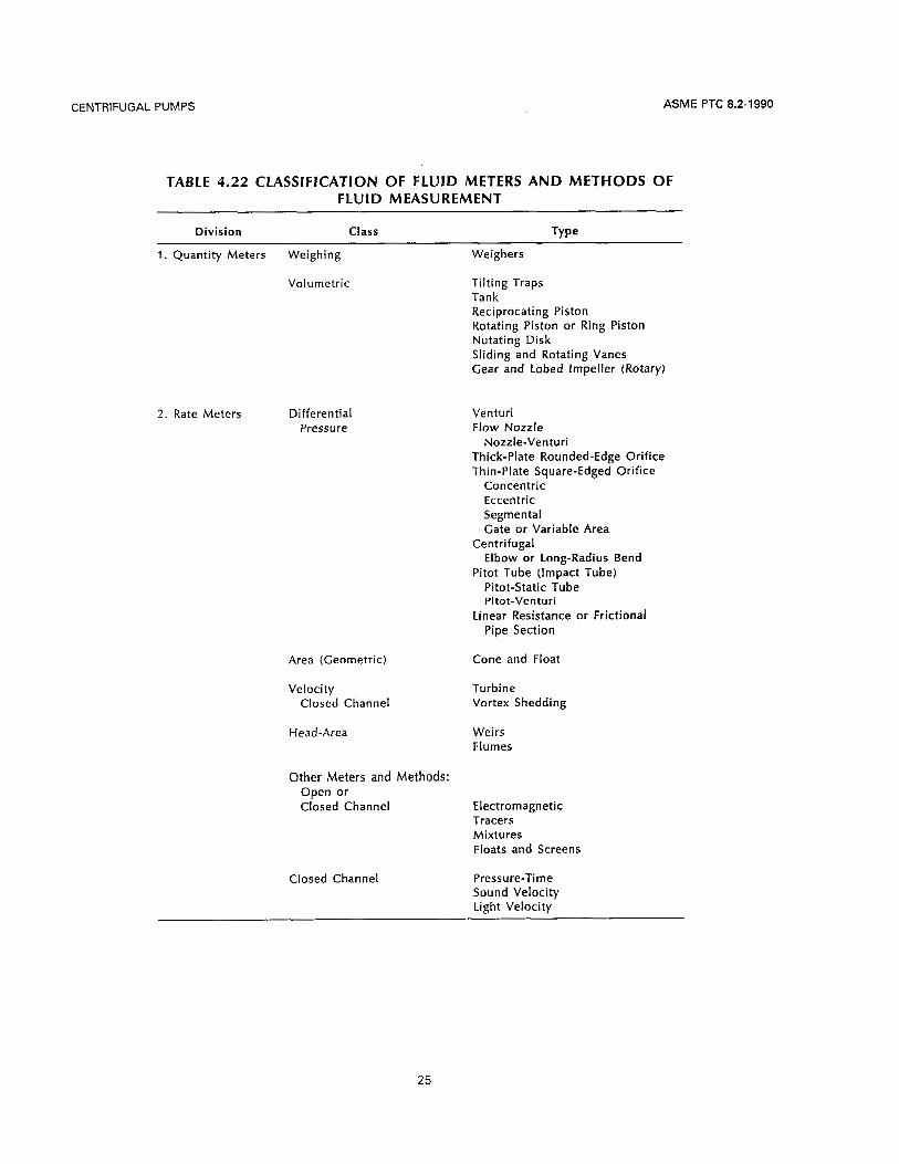
CAPACITY MEASUREMENT 4.22 Because of the wide range of viable flow mea- suring techniques available, Code users are referred to “Fluid Meters, Their Theory and Application.” In this Code (PTC 8.2), Table 4.22 lists a variety of ac- ceptable flow measuring devices. The Code user is cautioned, however, that the use of any device to satisfy Code requirements means that i ts calibration and accuracy must satisfy the criteria established in Table 1 .I 1 and throughout this Code.
24
CENTRIFUGAL PUMPS ASME PTC 8.2-1990
TABLE 4.22 CLASSIFICATION OF FLUID METERS AND METHODS OF FLUID MEASUREMENT
Division Class Type
1. Quantity Meters Weighing
Volumetric
2. Rate Meters Differential Pressure
Area (Geometric)
Velocity Closed Channel
Head-Area
Other Meters and Methods: Open or Closed Channel
Closed Channel
Weighers
Tilting Traps Tank Reciprocating Piston Rotating Piston or Ring Piston Nutating Disk Sliding and Rotating Vanes Gear and Lobed Impeller (Rotary)
Venturi Flow Nozzle
Thick-Plate Rounded-Edge Orif ice Thin-Plate Square-Edged Orif ice
Nozzle-Venturi
Concentric Eccentric Segmental Gate or Variable Area
Elbow or Long-Radius Bend
Pitot-static Tube
Centrifugal
Pitot Tube (Impact Tube)
Pitot-Venturi
Pipe Section
Cone and Float
Linear Resistance or Frictional
Turbine Vortex Shedding
Weirs Flumes
Electromagnetic Tracers Mixtures Floats and Screens
Pressure-Time Sound Velocity LiEht Velocity
25

ASME PTC 8.2-1990 CENTRIFUGAL PUMPS
Gage
Purge connection
Shut-off valve
urge feed pressure to not less than twice or more than three times that of maximum pressure to be measured)
Gate (shut-off) valve of material corrosion resistant to pressure medium
IMPORTANT - Always open this valve after purge is on. Always close valve before purge is turned off
GENERAL NOTE: For water purge, substitute a small rotometer for purge f low regulator.
FIG. 4.12.1 A TYPICAL AIR O R WATER PURGE SYSTEM
26

CENTRIFUGAL PUMPS ASME PTC 8.2-1990
.
Purging inlet valve
II [Capillary tubing
Drain
Gage
FIG. 4.1 2.2 A TYPICAL SEAL WITH INTERMITTENT PURGE
4.23 Quantity-type metering is usually accomplished by either weighing or measuring a quantity of fluid collected over a known time period or by measuring the time necessary to collect a known volume of fluid. These methods are more commonly used for calibrating rate-of-flow meters than for measuring pump capacity.
4.24 Rate-of-flow metering is usually accomplished by a venturi tube, flow nozzle, or an orifice plate, where a differential pressure is measured. The mea- surement is then used to calculate a flow rate.
4.25 Other devices, such as variable-area, impact head-area type or velocity type, along with acoustic or tracer techniques, may be used for capacity mea- surement provided their accuracy and repeatability can be demonstrated by acceptable calibration meth- ods and the parties to the test agree to their use.
VISCOSITY MEASUREMENT 4.26 When using liquids other than water, viscosity shall be known at three or more liquid temperatures that span the temperature of the test range. For a detailed discussion of viscosity measurement, see PTC 19.1 7 on Determination of the Viscosity of Liquids.
SPECIFIC GRAVITY DETERMINATION
4.27 When using liquids other than water, specific gravity may be determined by pycnometer, hydro- static weighing or hydrometer. Specific gravity deter- minations shall be made at three or more liquid temperatures that span the temperature range of the test. When it is known that the test liquid may exhibit significant variation in specific gravity over the test range, i ts specific gravity shall be determined im- mediately before and after the test. There shall be not more than a + 1 .O% variation of the specific gravity at the test temperature. When it is not possible to span the test temperature range, extrapolation can be used, provided the method of extrapolation is agreed upon by the parties to the test. For a detailed discus- sion of specific gravity determination, see PTC 19.1 6 on Density Determination.
VAPOR PRESSURE DETERMINATION 4.28 At any temperature less than the critical, all sin- gle component liquids exert a corresponding unique pressure above their liquid surface.
This is referred to as the "vapor pressure" at that temperature. For mixtures of completely miscible liq- uids, the vapor pressure is a function of mixture com- position, as well as temperature. Impurities such as dissolved gases and traces of volatile substances can cause the vapor pressure to vary appreciably from the true or equilibrium value of the pure liquid.
27

ASME PTC 8.2-1990
When it is necessary to determine the vapor pres- sure, the temperature of the liquid shall be measured. Using this value, the vapor pressure shall be found in the ASME Steam Tables for water (latest edition), or similar sources for liquids other than water.
TEMPERATURE MEASUREMENT
4.29 The temperature(s) of the pumped fluid may be determined by any of the following three measuring devices:
(a) etched-stem, liquid-in-glass thermometers; (b) thermocouples used with potentiometric in-
(c) resistance thermometers used with resistance
For a detailed discussion of temperature measure-
struments;
bridge instruments.
ment, see PTC 19.3 on Temperature Measurement.
4.30 When the temperature to be measured differs . from the surrounding temperature by more than
50”F, temperature-measuring devices are to be in- sulated. It is preferred that all temperature sensing instruments be installed directly into the liquid stream. When adequate support cannot be provided, thermowells may be used.
4.31 Temperature shall be measured as close to the section in question as possible, without having an effect on the measurements of pressure and flow rate. If the measuring section is in a region of high tem- perature gradient, the connection to, and the pipe immediately before and after, the various instru- ments, shall be insulated sufficiently to assure the accuracy of the temperature measurement.
ELECTRIC POWER INPUT/MOTOR EFFICIENCY MEASUREMENT
4.32 For Type A tests, the motor efficiency shall be determined by measurement in accordance with the latest revision procedures outlined in the following publications:
(a) “Standard Test Procedures for Polyphase In- duction Motors and Generators,” IEEE Standard I1 2
(b) “Standard Test Procedures for Direct Current Machines,“ IEEE Standard 11 3
(c) “Standard Test Procedures for Synchronous Machines,’’ IEEE Standard 11 5
For Type B tests, the motor manufacturer’s guar- anteed motor efficiency for the type, model, speed, and percent of rated load may be used to determine the input power to the pump, provided the motor i s manufactured according to NEMA Standards.
CENTRIFUGAL PUMPS
4.33 The power input to the pump shaft of a direct- connected motor-driven pump is equal to the prod- uct of the electrical input power to the motor and the motor efficiency at the observed load. The electrical input power to the driving motor shall be measured by any one of the following acceptable methods:
(a) two-wattmeter method (for three-phase mo- tors);
(b) one-wattmeter method (for dc motois or sin- gle-phase ac motors);
(c) polyphase wattmeter method (for three-phase motors);
(d) voltmeter and ammeter for dc motors; (e) voltmeter, ammeter, and measured power fac-
tor for ac motors per phase. For the proper application of the above measuring
methods, refer to PTC 19.6 (“Electric Measurements in Power Circuits”) or IEEE Standard 120.
In the case of submersible or canned pumps, power measurement may be made at the incoming end of the cable. Cable losses shall be taken into account and reported for Type A and Type B tests. The reported efficiency shall exclude cable and starter losses. Submersible cable requirements shall be in conformance with procedures outlined in the follow- ing publication: 0 American National Standard for Vertical Turbine Pumps - “Line Shaft and Submersible Types,” ANSI/ A W A E l 01.
4.34 Other acceptable means of measuring power include transmission dynamometers and torsion dy- namometers (see PTC 19.7 on Measurement of Shaft Power). These devices may be used in lieu of cali- brated motors and acceptable motor data (see paras. 4.32 and 4.33). When a driver other than an electric motor is used, an appropriate transmission or torsion dynamometer shall be used to measure pump input power. The transmission dynamometer shall be checked at test speed to assure that the balance is correct (against standard weights). Test speed shall be within 1% of pump speed. The torsion dynamom- eter shall be calibrated statically (measured angular deflection for a given torque). The transmission dy- namometer shall be calibrated dynamically at rated speed. Test speed shall not vary more than 1% from pump speed. The temperature of the dynamometer during the test shall not vary more than 10°F from the calibration temperature.
SPEED MEASUREMENT
4.35 The speed may be measured by revolution counters, including but not limited to tachometers,
28

CENTRIFUGAL PUMPS ASME PTC 8.2-1990
tachometer generators, optical or electrical revolu- tion pickup and frequency counters. In the case of a pump driven by an ac motor, the pump speed may be determined from observations of the mean fre- quency and motor slip.
4.36 A stroboscope may be used to determine ro- tative speed provided:
(a) the stroboscope shall be synchronized to line frequency and the slip counted; or
(b) the stroboscope shall have been demonstrated to be adequate to resolve the speed of rotation to 0.01% if direct readings are taken.
4.37 When the speed of rotation cannot be directly measured, mutually agreeable corrections based on voltage, frequency, and power shall be made to the motor’s rated speed.
NPSH TESTING
4.38 NPSH tests shall be conducted when agreed to by the parties to the test. The test arrangement se- lected and the procedure to be followed shall be agreed upon prior to the test. Directions for the com- putation of NPSH values are found in paras. 5.10 and 5.1 1. Guidance on interpretation of NPSH test results is provided in Appendix H. Descriptions of NPSH and cavitation phenomena are found in Appendix D.
4.39 NPSHR shall be determined as required by para. 3.1 2.
4.40 The complete single stage pump shall be used for both Type A and Type B tests. Only the first stage of multistage pumps shall be tested in its casing or a geometrically similar casing for Type A tests.
Type B NPSH tests may be conducted using the full pump assembly of a multistage pump. The first stage head may be measured directly or computed by di- viding the total head by the number of stages. Total measured head drop shall be applied against the first stage only. Inducers shall be considered part of the first stage. The test liquid temperature shall be es- sentially constant and as low as possible (see para. 3.1 5). It shall not exceed 175°F unless agreed to prior to the test [see para. 3.4(b)l. Four typical test arrange- ments for determining the NPSH characteristics of both horizontal and vertical pumps are shown sche- matically in Figs. 4.40.1, 4.40.2, 4.40.3, and 4.40.4.
Not all arrangements will be suitable for all types of pumps. Modifications of these arrangments will be acceptable as long as the desired results are achieved.
4.41 In Fig. 4.40.1, the flow is supplied from a pit having a free liquid surface. The NPSHA can be varied by changing the level in the suction pit. The maxi- mum NPSHA attainable is with the liquid at its high- est pit level. Losses in the suction pipe will reduce the net reading at all levels.
4.42 Figure 4.40.2 utilizes a constant level suction pit, with a throttling valve to change the NPSHA. Cav- itation at the valve should be avoided. Flow into the pit should be low velocity (less than 3 Ws) to avoid air entrainment and vortexing. Suction pipe, valve, and straightening vane losses will reduce the NPSHA.
CONSTANT CAPACITY TESTS
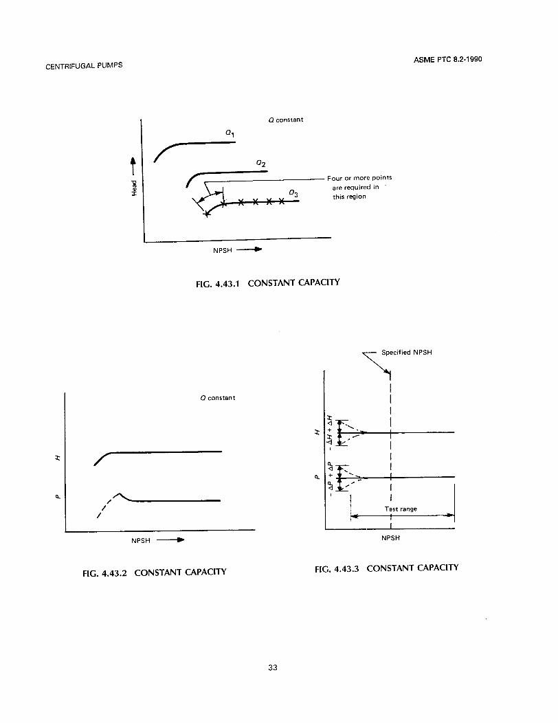
4.43 Figures 4.40.2, 4.40.3, and 4.40.4 show ar- rangements to provide constant capacity while vary- ing the NPSHA at constant speed. Plots of head versus NPSH (Fig. 4.43.11, and head versus NPSH and horsepower versus NPSH (Fig. 4.43.2) will give curves from which stable operation as indicated will show minimum NPSHR for various flows. NPSHA range for these tests shall be from an NPSH of 2 times the specified minimum NPSHA down to an NPSH corresponding to a significant deviation in head or horsepower. A minimum of eight test points shall be determined to define each head versus NPSH curve. At least three points shall be in the linear portion, one of a minimum deviation of IO%, and four or more to define the shape of the curve between the linear and minimum. In most cases, a deviation of &20% is sufficient (see Fig. 4.43.3).
A deviation of up to 50% may be required when the head at the specified capacity is very low (a few feet or less).
CONSTANT NPSH TESTS
4.44 As an alternate method, Figs. 4.40.1, 4.40.3, and 4.40.4 show arrangements to provide constant NPSH while head and capacity points change to pro- vide curves (Fig. 4.44.1) from which limits of flow for each NPSHR may be obtained. Flow range shall be from that head corresponding to 50% of the test ca- pacity down to a head that is 80% of the test head (see Fig. 4.44.2). Head reduction may be less if the break-off characteristic is established prior to that point.
29

ASME PTC 8.2-1990 CENTRIFUGAL PUMPS
FIG. 4.40.1 NPSH TEST ARRANGEMENT
Min. length
Straightening vanes
---__ -----Y
Constant level
FIG. 4.40.2 NPSH TEST ARRANGEMENT
30

CENTRIFUGAL PUMPS ASME PTC 8.2-1990
- Heating or cool ing coils
Isolation valve
Straightening vanes Control valve or back pressure valve
FIG. 4.40.3 NPSH TEST ARRANGEMENT
The minimum capacity for performing each NPSH test run shall be 50% of the capacity Q corresponding to the NPSH value selected. Each curve is defined by increasing the capacity until the measured head sig- nificantly deviates from the noncavitating head-ca- pacity curve to a minimum of 20% reduction in head
. (see Fig. 4.44.2). The test points shall be at 50% Q, 90% Q, and 2.5% Q increments thereafter until the 20% reduction in head (0.8H) has been achieved.
CALIBRATION 4.45 Calibrations
'4.45.1 Calibrations, records, and data for all instru- ments shall be made available to the parties to the test. All calibrations of the test instrumentation shall be traceable to the National Bureau of Standards or a basic reference standard (e.g., a mercury column).
Calibration data showing actual error at each point is preferable, but a manufacturer's calibration certif- icate stating the traceability and error band is ac- ceptable. Data may be considered as correct within the accuracy defined by the band of error which in- cludes all calibration points over the range of mea- sured data. For significant error of the instrument from the standard, corrections may be applied to in- dividual data points if the error is repeatable.
31
It is the responsibility of the testing facility to main- tain records of initial calibrations and the periodic recalibrations. Any instrument may be recalibrated before or after a test, if agreed upon by the parties to the test.
If an instrument is subject to a correction due to calibration, the actual reading of the instrument shall be recorded on the test data sheet along with the corrected value. The correction chart shall be in- cluded as part of the final test report.
4.45.2 Test instrumentation shall be calibrated .be- fore first use, taking care to ensure that calibration and test conditions are compatible. Test instrumen- tation is defined as any device used to measure the parameters of the test. This includes all primary and secondary devices. I t . i s preferable to calibrate the complete instrument system by applying a known in- put to the primary sensing device and reading the final output devices for calibration comparison. This is very easily done in the case of direct-reading de- vices such as Bourdon gages, but becomes more dif- ficult as the complexity of the instrumentation increases. When it is not practical to calibrate the components of the complete instrument system si- multaneously, separate calibration of primary sensing devices and'the readout equipment is acceptable.

ASME PTC 8.2-1990 CENTRIFUGAL PUMPS
Control valve or back pressure valve Pressure
Vacuum
4 Straightening vanes
r------ A
r- I n L - - - - - - - --
/
Pi---- Heating or cooling coils
Isolation valve 1
GENERAL NOTE: Arrangements shown are typical and may be used with any pump covered by this Code.
n
1 Isolation valve
- ___)
i
I
FIG. 4.40.4 NPSH TEST ARRANGEMENT
4.46 The frequency of instrument recalibration will depend on the instrument type, i ts frequency of use, i ts calibration history, and the data accuracy require- ments. A systematic program for recalibration shall be developed by the test facility personnel responsi- ble for the instrumentation and be based on these criteria. Documentation supplied by the instrument manufacturer, compiled by the user, or published in technical papers shall be available to support recali- bration frequency decisions. Agreement to test spe- cific calibrations either before, or both before and after, the test, may be reached in writing by the par- ties to the test. The frequencies prescribed in paras. 4.47 through 4.52 shall be ‘adopted.
4.47 Bourdon gages, weights scales, dial thermom- eters, and other devices with mechanical meter movements should have minimum six (6) month cal- ibration intervals.
4.48 Thermometers, thermocouples, and resistance temperature devices (RTD) should be calibrated be-
fore first use. Associated readout devices and leads shall have maximum twelve (12) month calibration intervals.
4.49 Strain gage devices such as pressure trans- ducers, torque meters, load cells, and target flow- meters shall be recalibrated every 12 months against a standard traceable to NBS.
4.50 Electrical measuring instrumentation such as voltmeters, ammeters, wattmeters, and pulse counters shall have six (6) month calibration inter- vals. Transformers used for stepping down voltage and current for input into the above meters shall be of instrumentation or metering grade and calibrated before first use. Recalibration of these transformers is not required unless rewound or exposed to tran- sients beyond manufacturer’s recommendations.
4.51 Rate meter calibration frequencies depend on the meter type.
32
CENTRIFUGAL PUMPS ASME PTC 8.2-1990
I 0 constant
I Q1
? I- 0 2 I z f
Four or more points are required in '
this region
NPSH 4
FIG. 4.43.1 CONSTANT CAPACITY
I '
0 constant
Q d
P + P 4 I
I
I NPSH 4
FIG. 4.43.2 CONSTANT CAPACITY FIG. 4.43.3 CONSTANT CAPACITY
33

ASME PTC 8.2-1990 CENTRIFUGAL PUMPS
P H - I
0.8H
1 Test Capacity ___)
FIG. 4.44.1 CONSTANT NPSH
r Test range for each NPSH (see Fig. 4 .44.1)
I
2-1/2 percent Q increments
I Predicted NPSH curve
I I
Test range for each NPSH (see Fig. 4.44.
I 0.5Q 0.9Q Q \ ' 0.8H
Test Capacity
1)
FIG. 4.44.2 CONSTANT NPSH
34

CENTRIFUGAL PUMPS ASME PTC 8.2-1990
4.51.1 After an initial calibration, verification of crit- ical dimensions, general condition, cleanliness, and pressure tap conditions i s required at intervals not greater than 12 months for meters without moving parts such as venturis, nozzles, and orifice plates. More frequent intervals of verification may be nec- essary for abrasive or dirty liquids. Additional verifi- cations or calibrations may be performed by prior agreement of the parties to the test.
A recalibration is required when dimensional changes are found which would affect the original calibration. These meters shall be calibrated with their associated piping unless the piping conforms to the straight run distances recommended in the ASME “Fluid Meters, Their Theory and Application.” When flange or pipe taps are utilized, they are considered as part of the meter, and the actual pipe or flanges must be included in the calibration.
4.51.2 Meters with mechanical movements and bearings such as turbine meters and paddle meters are more susceptible to errors due to wear. A 1 year recalibration interval is required. Since meters of this type are of various design, durability, and accuracy, the manufacturer’s recommendation on calibration and installation should be followed. Piping effects on calibration vary greatly and shall be considered dur- ing calibration.
4.51.4 It must be recognized that some flow meters are too large to calibrate using standard volumetric or gravimetric methods. In these cases, a calculation may be used based on the theory as given in ASME “Fluid Meters, Their Theory and Application.” Every attempt shall be made to verify this calculation by use of other flow-measuring devices such as a pitot traverse, comparison to another calculated meter, or dye injection.
4.52 Electric Motors - Drivers
4.52.1 Type A Test. Calibrated electric motors shall have an initial calibration by actual load testing, or if this i s impractical, calculation by the segregation- of-losses method may be used. These shall be done in accordance with the ANSVIEEE Standard (see para. 4.33) and performed on the actual motor. Calibra- tions based on tests of a similar motor or one of the same manufacturer, design, or frame size are not ac- ceptable. Recalibration or recalculation shall be done in the event of rewinding or major overhaul.
4.52.2 Type B Test. The manufacturer‘s guaran- teed efficiency values may be used to calculate the brake horsepower from measured electrical input.
4.51.3 Other designs such as electromagnetic and doppler meters shall have a maximum calibration in- terval of 1 year.
35

CENTRIFUGAL PUMPS ASME PTC 8.2-1990
SECTION 5 COMPUTATION OF RESULTS
5.1 If the test specifications require that multiple readings be taken at each test point (see para. 3.81, the arithmetic average of the readings taken shall be used in the computation of results.
NPSHR = NPSHR, - (:I
5.2 The observed readings, or the average of the ob- served readings, shall be corrected using either the accepted or the average of the pre- and post-test cal- ibration of each individual instrument. The exact methods of calculating capacity, head, power and NPSH will depend on the specific instruments em- ployed.
5.5 Head. Total pump head, in accordance with para. 2.2, is the algebraic difference between total discharge head and total suction head.
H = H, - H,
and 5.4 Adjustment of Results to Other Than Test Speed. To adjust the pump capacity, head, required NPSH and pump input power obtained at the speeds recorded during the test to any other speed within the range of speed variation given in Note (1) of Table 1 .I 1, the following formulas may be used. The sub- script t refers to the conditions obtained during the test.
Q =
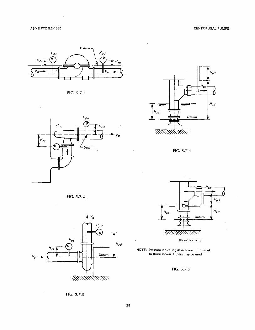
5.7 Figures 5.7.1 through 5.7.5 indicate typical gage and manometer arrangements for determining dis- charge and suction heads for various types of pump installations. It should be noted that in all cases Hz is the vertical distance from the datum (refer to Fig. 2.2) to the center line of the gage or zero on the manom- eter. Velocity head H, is determined at the point of gage attachment. H,,d and H,,,s should be corrected for the losses incurred between the pump discharge flange or coupling and the gage or manometer. Refer to paras. 4.5 through 4.22 for details relative to the various manometer and gages used.
37
ASME PTC 8.2-1990 CENTRIFUGAL PUMPS
FIG. 5.7.1
FIG. 5.7.4
I
FIG. 5.7.2
t vd
NOTE. Pressure indicating devices are not limited to those shown. Others may be used.
FIG. 5.7.5
FIG. 5.7.3
38

CENTRIFUGAL PUMPS ASME PTC 8.2-1990
5.8 On a vertical pump, similar to those indicated in Figs. 5.7.4 and 5.7.5, the entrance losses to the pump are charged to the pump. The average velocity head of the flows in the sump are small enough to be ne- glected. Therefore the total suction head is equal to Hz,
H, = 0 + H, + 0 = H,
5.9 Total Bowl Head. Total bowl head is defined in para. 2.2. As indicated in Fig. 5.7.5, the measuring section is located immediately downstream of the pump diffuser section. Therefore, total bowl head is equal to
H, = Hd - h,
where
5.1 0 Net Positive Suction Head Available (Test Con- ditions). Net positive suction head is defined in para. 2.2 as being the total suction head plus barometric head minus the vapor pressure head of liquid, ex- pressed in feet of the liquid and can be written as
NPSHA = H, + H,,, - H,
For arrangements similar to those shown in Figs. 5.7.1 and 5.7.3, where the suction side pressure is above the datum, the general equation can be trans- formed to
NPSHA = (+Hps + H, + H, + Hat) - H,
For arrangements similar to Fig. 5.7.2, where suction side pressure gage is below the datum, equation becomes
the the
NPSHA = (kH,, - H, + H, + Hat) - H,
For arrangements similar to those shown in Figs. 5.7.4 and 5.7.5, the general equation can be trans- formed to
5.1 1 Net Positive Suction Head Characteris- tics. NPSHR is determined by utilizing data from NPSH tests conducted in accordance with directions provided in paras. 3.12, and 4.38 through 4.44 of this Code.
5.1 i .1 In the case of a constant capacity test, as test NPSHA is reduced, the head generated by the pump will begin to change and break away from the linear portion of the plot of head versus test NPSHA. As NPSHA is further reduced, pump performance will be impaired. The method to be used in interpreting the test results, and in establishing the breakaway point (critical point), or a magnitude of deviation from non- cavitating conditions, shall be mutually agreed upon in advance by the parties to the test.
5.1 1.2 An alternative method of determining NPSHR is to utilize the data from NPSH tests conducted at constant test NPSHA. In this case, as capacity is in- creased, the head generated by the pump will de- crease and break away from the previously determined plot of head versus capacity for noncav- itating conditions. As attempts are made to continue to increase capacity, the head will begin to drop se- verely, tending toward a limiting capacity and im- paired pump performance. The method to be used in interpreting the test results and in establishing the breakaway point (critical point), or a magnitude of deviation from noncavitating conditions, shall be mu- tually agreed upon by the parties to the test.
5.12 Pump Input Power. Pump input power (brake horsepower) can be determined in a number of ways. For instance, if torque is measured in ft-lb, then
When using a calibrated motor, then
p = (pi) x (motor efficiency)
5.13 Pump Output Power. Pump output power (water horsepower) is the liquid horsepower deliv- ered by the pump and is equivalent to the rate of mechanical energy gained by the liquid passing through the pump.
39

ASME PTC 8.2-1990 CENTRIFUGAL PUMPS
5.14 Efficiency. Pump efficiency is the ratio of the pump output power to the pump input power.
5.15 Overall Efficiency. Overall efficiency is the ra- tio of the pump output power to the driver input power.
40

CENTRIFUGAL PUMPS
SECTION 6
ASME PTC 8.2-1990
REPORT OF TEST
6.0 Paragraphs 6.1 through 6.7 describe the mini- mum information which is required by this Code when reporting tests performed under this Code. Par- agraph 6.8 identifies addditional examples of infor- mation which may be added for convenience or required by agreement of the parties to the test.
6.1 Type of Test Conducted
(a) Overall Performance - A or B (b) NPSH - A, 6, or Not Conducted
6.2 General Information
(a) Name of party for whom the test is conducted (b) Location and elevation of user’s service instal-
lation for which the pump is to be tested (if known) (c) Date($ of the test(s) (d) Name and address of the test facility (e) Name of responsible supervisory test person(s) (0 Name($ of witness(es) (g.) Certification signature by the responsible per-
son from the test facility. (Note: Certification signa- ture for overall test results is certification that all instruments used are calibrated and satisfy the ac- curacy requirements of this Code.)
(h) Schematic diagram of the test setup identifying (not necessarily to scale) all dimensions which are mandated by this Code. (In addition, photographs and/or fully dimensioned sketches or drawings are recommended but not mandatory.)
6.3 Pump Identification
(a) Manufacturer (b) Type and model designations (c) Size (d) Serial number (e) Number of all stages, types, and diameters of
each (including any special first stage or inducer no- menclature)
(0 Nominal suction nozzle diameter (@ Nominal discharge nozzle diameter
6.4 Driver Identification
(a) Type of driver used for test (6) Nameplate data from driver (c) Nameplate data from any intermediate drive
transmission, if employed
NOTE: If a driver other than an electric motor drive is used, and nameplate data is not sufficient to identify energy source and con- ditions, such data shall be supplied with the test results. For ex- ample, steam conditions and flow rate are required for a steam turbine drive.
6.5 Test Instrumentation. For all instruments or in- strument systems used in the conduct of the tests, the following shall be reported:
(a) type of instrument; (6) manufacturer and serial number of each; (c) date of last calibration; (d) calibration correction charts or tables for each
instrument subject to a correction due to calibration.
6.6 Test Results
(a) Recorded Data. Data taken to directly deter- mine or report each test point required by this Code shall be provided. Tabulation of such data shall in- clude both raw (i.e., directly observedhecorded data) and calibration corrected data. Additional data re- corded to provide information for the balance of the performance curves shall be maintained by the test facility and are subject to review by the parties to the test.
In addition, data supporting performance deter- mination shall also be provided in raw and corrected form. These data shall include suction and discharge temperature, density/specific gravity of the test liquid (taken from the latest edition of the ASME steam ta- bles or water, measured or taken from suitable ref-
41

ASME PTC 8.2-1990 CENTRIFUGAL PUMPS
erences for liquids other than water), barometric head (when conducting NPSH tests), speed of rota- tion, and driver input power or data from which it is computed.
(6) Performance Results. For each test point man- dated by this Code, the following computed or di- rectly measured data shall -be reported as a single '
value for each of the following: (3) capacity; (2) total suction head (may be excluded if the
total pump head is measured ,directly. Always in- cluded when NPSH testing is conducted.);
(3) total discharge head (may be excluded if the total pump head is measured directly.);
(4) total pump head; (5) pump input power; (6) pump output power; (7) pump or bowl assembly efficiency; (8) net positive suction head (when agreed
(9) temperature variation at both suction and discharge during test;
(10) temperature change from suction to dis- charge.
(c) Graphic Presentation of Results. Performance curves of head versus capacity, horsepower, NPSHR (if NPSH is tested), and efficiency shall be prepared and certified in the same manner as the overall test report. All points mandated by this Code shall be identified on the curves. If NPSH is tested, the NPSH
upon);
test curves shall be included and shall identify the points mandated by the Code. The criteria for percent head drop used as the basis for the NPSH curve shall be stated on the graph.
6.7 Calculation. For Type A tests, certified copies of calculations performed to arrive at the reported re- sults shall be supplied with the test report. For Type B tests, the calculations may be retained by the test facility.
6.8 Other !nformation. By agreement of the parties to the test, additional information such as that ex- emplified by the following may be included in the report:
(a) instrument system diagrams; (6) detailed dimensional description of the pump
or inclusion of a detailed drawing of the pump or reference to a detailed drawing'giving the information agreed upon;
fc) mechanical operating characteristics informa- tion such as water and/or airborne noise, vibrations, bearing temperatures, cooling water flows, various injection or leakage flows, and post-test inspection results.
The added information allowed by this paragraph is for the convenience of the parties to the test. It is not mandated by PTC 8.2.
42

CENTRIFUGAL PUMPS ASME PTC 8.2-1990
APPENDIX A SUMMARY OF AGREEMENTS BY THE PARTIES
TO THE TEST
This Appendix cover agreed upon by the format of this listing
's all the items noted in this Code to be determined and parties to the test, prior to the test. Compliance with the is nonmandatory.
Pump Designation Service Station
Model No. Serial No.
Appropriate Information Identifying the Test and Parties to Test
Code Paragraph Topic Agreement
1.5 Test Type: A or B (or mixed)
1.7 Test facility if outside manufacturer's facilities
1.10 Other codes
1.11 Method of adjusting the test results to speeds outside the range of the allowable deviations given in Table 1.11 for Type A tests
1.12 Specific uncertainty analysis required for this test
3.3 Envelope of equipment to be tested
3.4(a) Choice of NPSH testing
3.4(b) Test liquid and its properties
3.4(c) Location of test
3.4(d) Test instrumentation and test personnel to be provided by whom
3.4(e) Test setup and procedures to be used
3.4(f) Driver to be used
3.404 Scale factor if a sub-scale model is to be tested
43
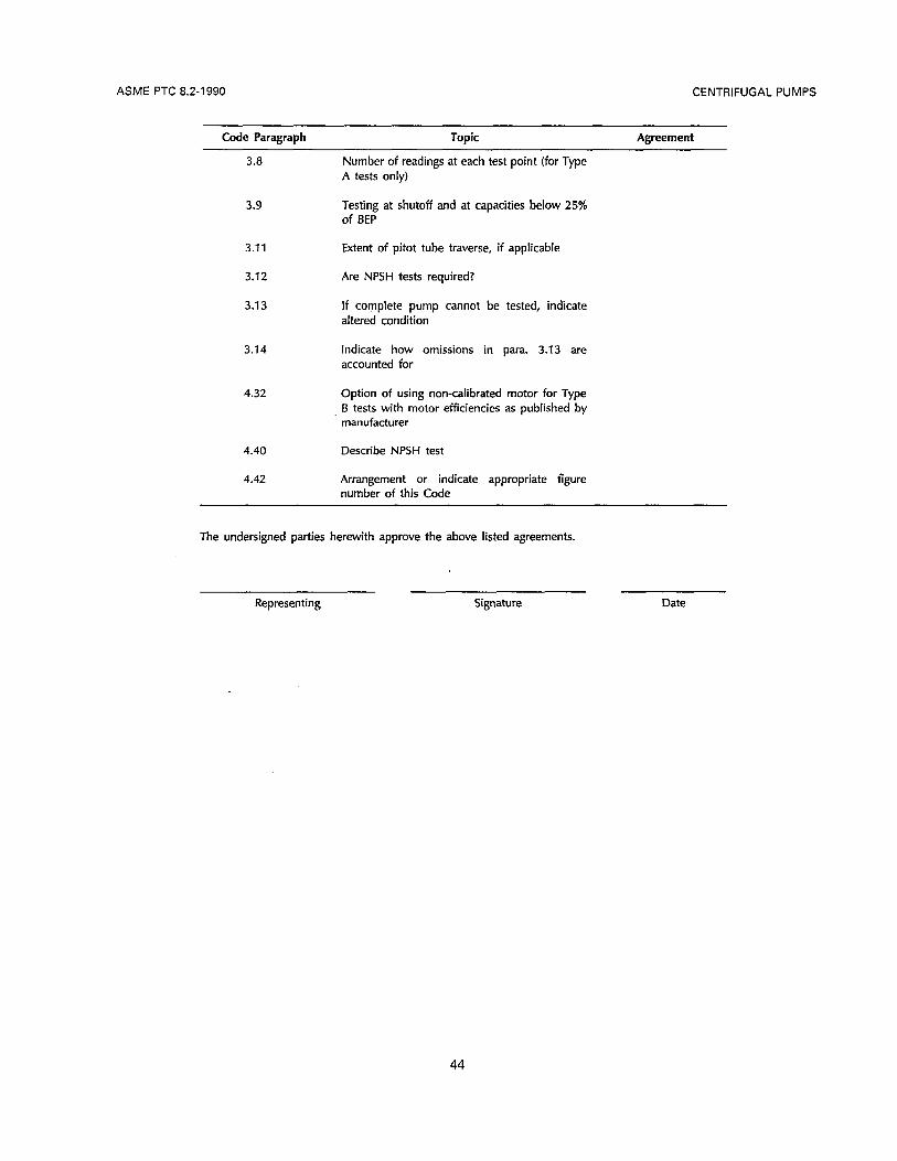
ASME PTC 8.2-1990 CENTRIFUGAL PUMPS
Code Paragraph Topic Agreement
3.8 Number of readings at each test point (for Type A tests only)
3.9 Testing at shutoff and at capacities below 25% of BEP
3.1 1 Extent of pitot tube traverse, if applicable
3.12 Are NPSH tests required?
3.1 3 If complete pump cannot be tested, indicate altered condition
3.14 Indicate how omissions in para. 3.13 are accounted for
4.32 Option of using non-calibrated motor for Type B tests with motor efficiencies as published by manufacturer
4.40 Describe NPSH test
4.42 Arrangement or indicate appropriate figure number of this Code
The undersigned parties herewith approve the above listed agreements.
Representing Signature Date
44

CENTRIFUGAL PUMPS ASME PTC 8.2-1990
APPENDIX B TEST CRITERIA LOCATOR FOR TYPE A AND TYPE B TESTS
Only requirements that vary with test type are listed.
Code Requirement
Item Topic Para. Type A Type B
1
2
3
4
5
6
7
8
9
10
11
Test Type recommendation
Number of readings per test point
Number of test points
NPSH test to be con- ducted at the following
pacities minimum number of ca-
Test of vertical diffuser pumps
Instrument accuracies and allowable fluctuations of test instrument readings
Number of pressure taps - Suction - Discharge
Motor calibration
Multistage pumps NPSHR head basis
Test report information re- quired
Test speed
3.2 Custom engineered Standard commer- application cia1 pump
3.8 5 minimum One
3.9 10 minimum 8 minimum
3.12 Rated, runout and One point as spec- 4.39 min. operating ified
3.14 Allows reduction of Allows bowl tests column and shaft
Table 1.1 1 See Table 1.1 1 See Table 1.11
4.7.1 Four Four
Single Single
4.32 Required Not required
4.40 Test first stage only Allows testing of complete pump
6.0 See Section 6 See Section 6
1.11 Equal to operating May be different speed or within and results ad- the range of allow- justed to operat- able deviations ing speed (See Table 1.1 1)
45

CENTRIFUGAL PUMPS ASME PTC 8.2-1990
APPENDIX C UNCERTAINTY ANALYSIS EXAMPLE
C1 The following analysis provides an example use of PTC 19.1 Measurement Uncertainty for the computation of uncertainty regarding centrifugal pump test parameters. The specific example chosen is the detailed analysis of the data used to develop the Type A information provided in Para. 1 .I 2 of this Code. Refer to PTC 19.1 for specific definition of terms and further development of the example.
C2 Type B information in Para. 1 .I 2 was computed in the same general manner as that for Type A, in accordance with PTC 19.1 , and using the requirements for Type B tests from Table 1 .I 1 of this Code.
C3 The example analysis i s shown in Table C1.
The following equations are used in determining the test results, and they will be used in the subsequent uncertainty analysis.
or
P (QIA)' Head = - + - P 2 g c
where A = (d4) D2
Efficiency (q) = (") (Ht) / (1.341P) 3960
or
Efficiency (11) = (SG) Q (HJ 3960 (P) 1.341
For Discharge Head:
A, = (d4) Dd2 (area of discharge pipe)
47

ASME PTC 8.2-1990
The following equation is used to calculate the absolute bias limit:
sHd = [(e,, X B,J~ + (e, x + (e, X sQ)z + (e, x ~ , ) 2 1 1 ~
In similar fashion, the absolute precision index is calculated as follows:
SHd = [(e,, x SpZ)’ + (e, x S,)’ + (0, x SQ)’ + ( e D d x Sm)2]‘n
Uncertainty is calculated by the following:
u,,, = [BHd + (tg5 x S,)l
Also,
CENTRIFUGAL PUMPS
(1 1
For Discharge Head:
The following list of bias limits and precision indices is based on experience and is made for the independent parameter of the preceding equations for head and efficiency. Degrees of freedom is greater than 30.
Parameter Bias Limit Precision Index Sensitivity (6) p2 21.75 psi = 2252 psf k2.0 psi = r 2 8 8 psf 0.01 68 ft3/lb P 2 0.004 Ib/ft’ r 0.002 1b/ft3 -26.01 ft‘/lb Qt k20.0 gpm = r0.0446 cfs 22.0 gpm = k0.00446 cfs 0.108 s/ft2 Dd %0.001 in. = -c0.0000833 ft 0 -0.957

CENTRIFUGAL PUMPS ASME PTC 8.2-1990
TABLE C1 UNCERTAINTY SUMMARY TABLE ~~~~~ ~~~~ ~ ~ ~ ~ ~ ~~
UA,, UR,,
Result X B 2s Abs. % Abs. %
H, 1545.5 ft 4.23 ft 5.58 ft 9.81 ft 0.63 7.00 ft 0.45 H, 39.57 ft 0.302 ft 0.28 ft 0.582 ft 1.47 0.412 ft I .04 H, 1505.93 ft 4.24 ft 2.79 ft 9.82 ft 0.65 7.01 ft 0.47 I, 75.03% 0.0098 0.00091 0.01 16 1.55 0.01 00 1.33
Q 2487.7 gpm 19.94 gpm 3.30 gpm 23.24 gpm 0.93 20.21 gpm 0.81 H 1472.7 ft 5.09 ft 4.24 ft 9.33 ft 0.63 6.62 ft 0.45
HdC 1511.3 ft 5.12 ft 4.28 f t 9.40 ft 0.62 6.67 ft 0.44
HSc 38.70 ft 0.305 ft 0.1 74 ft 0.479 ft 1.25 0.351 ft 0.91 P 875.33 kW 9.09 kW 2.58 kW 11.67 kW 1.33 9.45 kW 1 .oa
where
H, = H, = H, =
Ir =
Q = H = H,, =
H., =
P =
Note: Degrees of freedom for all results is >30, so t,, = 2.
Test Discharge Head Test Suction Head Test Total Head Test Efficiency Flow corrected for speed Total head corrected for speed Discharge head corrected for speed
Suction head corrected for speed
Power corrected for speed
BHd = i(0.0168 X 252.00)l + (26.01 X 0.004)2 + (0.108 X 0.0446)2 + (0.957 X 0.0000833)2]'R
BHd = k4.23 ft (bias limit of discharge head)
SHd = I(0.0168 X 288)2 + (26.01 X 0.002)2 + (0.108 X 0.00446)2 + Ozl ln
SHd = k4.84 ft For an average of three readings, N = 3. So, Swd = 4.84/3In = 22.79 ft (precision limit of discharge head)
Substituting these limits into the uncertainty E q . (3) yields:
U,,, = [4.23 + (2 x 2.79)J = 29.81 ft at - 99% coverage or
U,,JHd = 9.8111545.5 = 20.63% at -99% coverage
Similarly,
U, = [(4.23)2 + (2 x 2.79)2]1R = k7.00 ft at -95% coverage or
U,JHd = 7.00J1545.5 = r 0.45% at - 95% coverage
The same procedure as above is then followed below for the remainder of the test parameters. 1
49

ASME PTC 8.2-1990
For Suction Head:
CENTRIFUGAL PUMPS
A, = (7r/4)D,Z (area of suction pipe)
aHs - 1 1 ap1 P
e , = - - aHs p, (1 6.27) (1 44) aP P2
ep = - _ - aHs Q, aQ, 4’gc
e =
59.4 - 0.01 68 ft3/lb
- = - - (59.4)’
(1.62)2 (32.2)
= -0.664 ft4/lb
(5*605) = 0.0663 s/ft2 I ,
- - aHs - - 2Q: 2(5.60512 aD, (6/4)2D,”gc eDs = - ( ~ / 4 ) ~ (1 .94)5 (32.2) = -0.115
Parameter Bias Limit Precision Index Sensitivity (e) PI +-0.125 psi = * 18 psf 20.10 psi = t 1 4 . 4 psf 0.01 68 ft3/lb P k0.004 Ib/ft’ 20.002 1b/ft3 -0.664 ft4/lb Q, 0, *0.001 in. = ?0.0000833 ft 0 -0.51 1
k20.0 gpm = 20.0446 cfs k2.0 gpm = 50.00446 cfs 0.0661 s/ft2
For averaged result of 3 readings, N = 3. So, SH, = 0.242/3j2 = 20.140 ft
U,,, = L0.302 + (2 x 0.14O)J = a0.582 ft at - 99% coverage
U,,JH, = 0.582/39.57 = & 1.47% at - 99% coverage ,,
or
U,, = [(0.302)’ + (2 X 0.1 40)2]1/2 = k0.412 ft at - 95% coverage or
U,JH, = 0.412/39.57 = +1.04% at - 95% coverage
For Total Head:
All sensitivities are I by inspection.
5, = [(l X 4.23)’ i- (1 X 0.302)211’2 = C4.24 ft
S., = [(I X 2.7912 + (1 X 0.140)21’n = k2.79 ft
D 50

CENTRIFUGAL PUMPS ASME PTC 8.2-1990
U,,, = t4.24 + (2 x 2.79)l = r9.82 ft at -99% coverage
U,,dH, = 9.82/1505.93 = r0.65% at -99% coverage or
U,, = [(4.24)2 +- (2 x 2.79)211n = 27.01 ft at -95% coverage
or
U,JHr = 7.01h505.93 = 20.47% at -94% coverage
For Test Efficiency:
- - al l , Qr W r ) (2515.70) (1505.93) = o.788 dSG 3960 (PJl.341 = 3960 (905.1 7) 1.341
-
Parameter Bias Limit SC t0.0002 Q, f 20.0 gpm H, iz4.24 ft p, 29.0 kW
Precision Index Sensitivity (0) rc_0.0001 0.788 t 2 . 0 gpm 0.000298 l/gpm
k0.5 kW -0.000829 l/kW 52.79 ft 0.000498 l/ft
8, = I(0.788 X 0.0002)2 + (0.000298 X 20.0)2 + (0.000498 X 4.2412 + (0.000827 X 9.0)2]'n B, = -C0.00980 S, = [(0.788 X 0.0001)2 + (0.000298 X 2.0)2 + (0.000498 X 2.79)2 + (0.000827 X 0.5)2]1n S, = 20.00157 For an average of three readings, N = 3. So, S, = 0.00157/3'n = C0.000906
U,,, = [0.00980 + (2 x 0.000906)] = -C0.0116 at -99% coverage
U,,dq = 0.01 16/0.7503 = -I 1.55% at -99% coverage
U,, = t(0.00980)2 + (2 x 0.000906)2]1n = zkO.0100 at -95% coverage or
U,Jq = 0.0100/0.7503 = 21.33% at -95% coverage
or
51
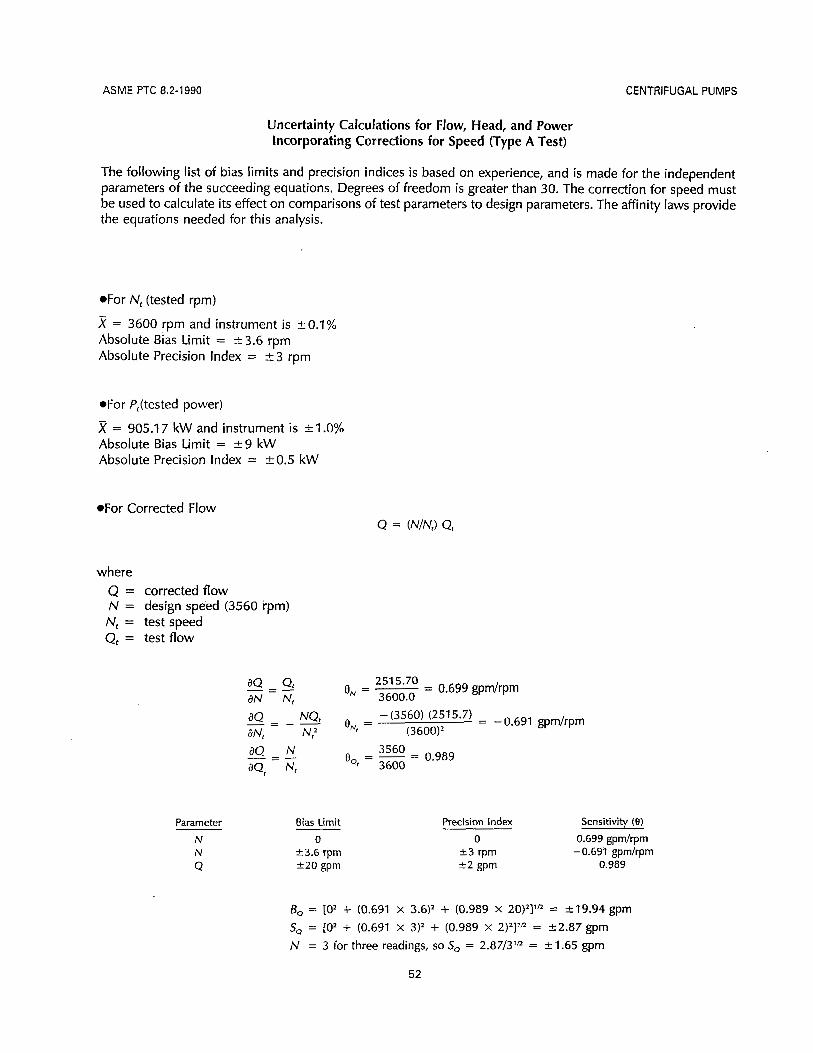
ASME PTC 8.2-1990 CENTRIFUGAL PUMPS
Uncertainty Calculations for Flow, Head, and Power Incorporating Corrections for Speed (Type A Test)
The following l ist of bias limits and precision indices is based on experience, and is made for the independent parameters of the succeeding equations. Degrees of freedom is greater than 30. The correction for speed must be used to calculate its effect on comparisons of test parameters to design parameters. The affinity laws provide the equations needed for this analysis.
.For N, (tested rpm)
x = 3600 rpm and instrument is +-0.1% Absolute Bias Limit = c3.6 rpm Absolute Precision Index = 2 3 rpm
*For /‘,(tested power)
x = 905.1 7 kW and instrument is + I .O% Absolute Bias Limit = +-9 kW Absolute Precision Index = +0.5 kW
.For Corrected Flow
where Q = corrected flow N = design speed (3560 rpm) Nt = test speed Q, = test flow
dQ Qt 251 5.70 dN Nr
O N = - = 3600.0
0.699 gpmhpm - = -
Parameter Bias Limit N N
Q
0 k 3.6 rprn +.20 gprn
Precision Index Sensitivity (9) 0 0.699 gprnhprn
2 3 rpm - 0.691 gpm/rpm 2 2 gprn 0.989
B, = io2 + (0.691 X 3.6)’ + (0.989 X 20)2]1R = &19.94 gpm sQ = LO’ + (0.691 X 312 + (0.989 X 2)2]1n = 42.87 gpm N = 3 for three readings, so So = 2.87/3lR = +- 1.65 gpm
52

CENTRIFUGAL PUMPS ASME PTC 8.2-1990
*For Corrected Head
where H = corrected total head H, = test total head
Parameter Bias Limit N
N, Ht
0 -c 3.6 rpm k4.24 ft
Precision Index Sensitivity (9)
+ 3 rpm - 0.81 8 fthpm f2 .79 ft 0.978
0 0.827 ft/rpm
B, = [O’ + (0.818 X 3.6)’ + (0.978 X 4.24)2]’R = 25.09 ft S, = [O’ + (0.818 X 3)2 + (0.978 X 2,79)2]1R = 23.67 ft N = 3 for three readings, so S, = 3.6713’” = k 2 . 1 2 ft
The above equations may also be used to calculate bias and precision limits for corrected discharge and suction head.
Corr. Discharge Head: B, = r4.23 ft Corr. Suction Head: B, = &0.302 ft S,,, = t2.79 ft SHs = 20.140 ft
e, = 0.849 e, = 0.0217 eNr = -0.840 e,, = -0.0215
e, = 0.978 eHs = 0.978
6Hdc = [02 + (0.840 x 3.6)’ + (0.978 x 423)2]’/2 = 25.12 ft S.,, = [O’ + (0.840 X 3)’ + (0.978 X 2.79)2]’R = k3.71 ft/31R = 52.14 ft BHSc = [O’ + (0.021 5 X 3.6)’ + (0.978 X 0.302)2]’n = t0.305 ft SHsc = 10’ + (0.0215 X 3)‘ + (0.978 X 0.140)2]’R = ?0.151 ft/3ln = 20.0872 ft
*For Corrected Power P = (N3/N,3)Pt
where P = corrected power
P, = test power
53

ASME PTC 8.2-1990 CENTRIFUGAL PUMPS
Parameter Bias Limit 0
23.6 rpm t 9.00 kW
(3560)’ (3600)’
= 0.967
Precision Index Sensitivity (e) 0 0.738 kW/rpm
?3 rpm -0.729 kW/rpm e0.50 kW 0.967
B, = 10’ + (0.729 x 3.6)’ + (0.967 x 9.00)21’n = 29.09 kW Sp = [O’ + (0.729 X 3)* + (0.967 X 0.50)2]1” = k2.24 kW N = 3 for three readings, so Sp = 2.2413’” = rt1.29 kW
UNCERTAINTIES
Substituting the above bias and precision limits in the uncertainty equation provides the total test uncertainty, including the correction for speed. (Note: Underlined uncertainties are the values used in para. 1.12.)
.For Corrected Flow
UADD = l19.94 + (2 X 1.6511 = k23.24 gpm at -99% coverage
U,,,dQ = 23,2412487.70 = 20.93% at -99% coverage Of
U,, = [(19.94)2 + (2 x 1.65)2]1n = r20.21 gpm at -95% coverage or
U,JQ = 20.2112487.70 = 20.81% at -95% coverage
[5.09 + (2 X 2.12)] = k9.33 ft.at -99% coverage
9.3311472.7 = 20.63% at -99% coverage or
[(5.09)2 + (2 x 2.12)’l’” = 26.62 f ta t -95%coverage
6.6211472.7 = 20.45% at -95% coverage or
[5.12 + (2 X 2.14)] = &9.40 ft at -99% coverage
9.40/1511.3 = 20.62% at -99% coverage or
[(5.12)’ + (2 x 2.14)211R = k6.67 ft at -95% coverage
6.6711 51 1.3 = +- 0.44% at -95% coverage or
54

CENTRIFUGAL PUMPS
.For Corrected Suction Head:
U A D D = 10.305 + (2 x 0.0872)l = k0.479 ft at -99% coverage or
UADJHsc = 0.479138.4 = 51.25% at -99% coverage
U,, = [(0.305)2 + (2 X 0.0872)2]1R = 50.351 ft at -95% coverage or
URSJHr, = 0.351138.4 = kO.91% at -95% coverage
.For Corrected Power
U,,, = 19.09 + (2 x 1.2911 = 2 11.67 kW at -99% coverage
U,JP = 11.671875.33 = -c 1.33% at -99% coverage or
ASME PTC 8.2-1990
U,, = [(9.09)2 + (2 X 1.29)2]1” = k9.45 kW at -95% coverage or
URSJP = 9.451875.33 = 51.08% at -95% coverage
55

CENTRIFUGAL PUMPS ASME PTC 8.2-1990
APPENDIX D CAVITATION
Dl Introduction. ”Cavitation” as used in pump test- ing usually refers to the formation of a gaseous phase in the flow of a liquid by a decrease in the fluid static pressure caused by the fluid motion. In a pure liquid, the gaseous phase consists only of the vapor of the liquid at a pressure equal to the vapor pressure of the pure liquid at the temperature of the liquid. next to the vapor. Most pump testing is carried out with water which unless deaerated contains dissolved gas, usually air. The “cavity” for the gaseous phase formed then will contain both the vapor phase of the liquid and gas that has come out of solution, and the pressure of this gaseous mixture is equal to the sum of the partial pressures of the two. It is necessary that the local liquid static pressure be less than the ”sat- uration” pressure for the dissolved gas to come out of solution. This process is a dynamic one controlled by mass diffusion and the detailed geometry of the cavitating flow; hence the gas partial pressure in a cavitating flow is usually not known. If the liquid is a multicomponent one, such as a mixture of hydrocar- bons, then the gaseous phase in a cavitating flow may consist of the partial pressures of the various com- ponents as well as dissolved air.
“Boiling” is also a process of forming a gaseous phase in a liquid and it is caused by heating the liquid so that the vapor pressure exceeds the local liquid static pressure. The two processes, cavitation and boiling, are somewhat similar in this respect except that in cavitation the gaseous phase formation is usu- ally caused by dynamic pressure reduction.
There is an intermediate condition possible for cav- itation in pumps, in which the normal growth of a “Cavity” is accompanied by a significant cooling of the liquid layers next to the cavity, thus decreasing the normal vapor pressure of the liquid. The cavity pressure is thus decreased, and as a consequence, the pump can operate with a lower suction pressure or NPSH for the same cavitation performance. This is called the “thermodynamic” effect in the pump cavitation literature and may become important for
fluids having vapor-to-liquid density ratio significantly greater than that of cold water.
D2 Consequences of Cavitation. The consequences of operation with cavitation include performance changes to the normal capacity rate characteristic, erosion of structural components, noise, and altera- tion of the unsteady pump behavior, thereby affecting system’stability.
Pump efficiency and head are usually decreased at constant speed and flow with onset of cavitation; the permissible amount of this decrease depends upon the particular application. In many commercial ap- plications, up to 3% head decrease may be an ac- ceptable amount to define the acceptable NPSHR; in other cases, such as those requiring long life, as little as 0.5% or less might be needed. A change in noise, both airborne and waterborne, and/or vibration, may also be detected in cavitation conditions.
D3 Detection of Cavitation. The frequently ac- cepted 3% head drop of cavitation performance gen- erally occurs with significant cavitation development in the inlet blading. “Inception” or first appearance of cavitation is usually determined visually under stroboscopic lighting or, less commonly, by acoustic means and has no influence on head or power. The ratio of NPSH at inception to the NPSH at which “defined” cavitation occurs, may vary roughly from 2 to 20 depending upon the specific speed, blade shape details and fraction of design flow. It has been generally conceded in the.pump industry that “cavi- tation-free” operation of commercial pumps over normal ranges of operation is economically unfeasi- ble, yet considerations of life under cavitation erosion may require NPSH values significantly greater than the 3% value mentioned but less than that of incep- tion. For this purpose,recourse is often made to direct visual observation of the cavitation in the impeller
57

ASME PTC 8.2-1990
inlet with stroboscopic illumination. As a practical matter, such observation is limited to cold water pumps and on a size scale agreed to between test parties. There the location, cause and observed form of cavitation are readily visible from inception to de- veloped states.
Because almost all pump operation occurs with some extent of cavitation leading eventually to ma- terial erosion, an alternative type of test has been used in which soft coatinis are applied to blade inlet regions. These coatings may be paint, dye, electro- platings, or in one case frangible microcapsules of dye which may then be eroded by -cavitation within only a few minutes. The locations and extent of cav- itation are then "witnessed" by the coatings but it is problematic whether such tests can be used to pre- dict actual machine life.
D4 Forms of Observed Cavitation. The physical ap- pearance and forms of cavitation at inception and at more developed conditions of operation may differ widely; cavitation may occur on the blade surface either as an attached cavity or as a disconnected stream of travelling, growing and collapsing bubbles. Cavitation also occurs in the blade tip clearance (if any) and wearing ring leakage flows, and usually then as clouds of bubbles. The "attached" cavities vary widely in form; the cavity itself sometimes appears as an envelope of small recirculating cavitating bub- bles, as a "frosty" surface of more or less wedge shape seen from above with apex upstream, and in some cases as a two-dimensional nearly glassy sheet springing from the leading edge.
Several phenomena are believed to govern these forms, chief of which is the Reynolds number, and second is the air content of the liquid. The total air content of liquid can be measured with a Van Slyke apparatus. For example: the total air content contains both free air existing in the form of microbubbles 5 to 100 micrometers diameter typically and dissolved gas. Although both are important for cavitation, the free microbubbles are believed to be the more im- portant. A standard test apparatus for microbubbles is not yet available; for this reason, the total gas con- tent is often recorded so that relative degree of gas saturation of the liquid is at least known.
Both the Reynolds number' and surface roughness determine if a laminar or turbulent flow prevails at
'Here ant consistent measure of Reynolds number is satisfactory, e.g., inlet tip speed times blade thicknesdkinematic viscosity.
CENTRIFUGAL PUMPS
blade inlets; frequently, model test pumps experience a leading edge laminar separation whereas the full scale may not. The physical forms and scaling laws of cavitation development of these two flows are known to be different. From this it would seem very desirable to carry out model cavitation tests at the highest possible Reynolds number.
The concentration of free-air microbubbles has been shown to have a major effect on cavitation in- ception and even on developed cavitation for special cavitation test bodies, shear flows and propellers. The normal amount or fraction of volume occupied by these microbubbles is still very small, typically being .less than O.Ol%, and is thus far removed from being a "two-phase" flow in which significant performance changes can occur. Pump cavitation is of course sub- ject to the same physical phenomena, but perhaps because of the focus on operation with a significant amount of cavitation, the "scaling" effects discussed above have not been as controlling as for these other flows.
D5 Implications for Pump Testing. The accepted scaling rules for cavitation in general, including the thermodynamic effect, make use of the difference be- tween upstream total head or pressure and the head or pressure within the cavity. The cavity pressure dif- fers from the vapor pressure of the surrounding liquid by the presence of the gas partial pressure, and the vapor pressure itself there may not be the same as that of the upstream bulk liquid if substantial cooling of the growing region of cavitation occurs (this is the thermodynamic effect). The number of the growing cavitating regions/bubbles is related principally to the free microbubbles concentration, which is itself in- directly related to total air content. The normal mea- sure of suction pressure or head is the suction total head minus the vapor pressure of the incoming pure fluid or NPSH. For the reasons mentioned, this vapor pressure may differ from the one actually governing the development of cavitation.
All these complex physical phenomena suggest that a single physical scaling law is unlikely to cover all cases of interest and this has turned out to be so in a wide variety of situations for cavitation inception as well as for cavitation erosion. There are some use- ful guidelines, however, that can be inferred from these phenomena applicable to cavitation or NPSH testing of pumps, as follows.
(a) Cavitation testing should be done at the highest Reynolds number possible with available speed and power limitations.
58

CENTRIFUGAL PUMPS ASME PTC 8.2-1990
(b) Where possible, tests of models should be made at the same tip speed and fluid as the proto- type, so that the relative amount of gas saturation will be the same in test and prototype test fluid. This does not mean the microbubble concentrations are equal in the two cases but it is an attempt to make them
(c) In any case, it i s useful to monitor total gas content of the liquid as a normal data item in cavi- tation testing.
(d) For special “engineered” pumps, it has be- come more customary to carry out visual tests of the pump inlet to determine the NPSH for inception, the location of inception around the inlet, and the type and extent, of cavitation region observed on or near the impeller inlet edges of the blade at the duty points of the application. The extent of the cavitation so observed, together with the tip speed, can have an important bearing on the service life of the pump, along with other suction parameters.
so.
D6 Discussion. Cavitation is one of the most im- portant factors affecting satisfactory pump operation and service life. Yet many aspects of cavitation are too little known to recommend standard test proce- dures. One such effect, briefly mentioned, is the un- steady behavior of a cavitating pump within the hydraulic circuit of which it is a part. The well-known phenomenon of pipeline acoustic resonance is one such case. Another is the “low frequency’’ surge or chugging that occasionally happens. The pump plays an important part in these sometimes hazardous os- cillations and cavitation is an essential feature of this behavior. To characterize the cavitation pump behav- ior for these unsteady flows requires measurement of six frequency dependent parameters in addition to the usual NPSH test. Such measurements are still too
few and instrumentation is still insufficiently devel- oped to recommend standard tests at the present time.
The prediction of cavitation damage or erosion for new applications continues to be a most difficult problem. Cavitation erosion is of vital importance to users and manufacturers alike and is therefore a sub- ject of intense current study.
Further Readings
(1) Handbook of Fluid Dynamics, Streeter, V. L., ed.,seeed., see Chapter 12, “Cavitation,” by Eisen- berg, P. and Tulin, M., 1961.
(2) Cavitation State of Knowledge, (Robertson, J. M., and Wislicenus, G. F., eds.), ASME Vol. 69, especially article by Hoil, J. W., “Limited Cavitation,” pp. 26- 64.
(3) Cavitation, Knapp, R. T., Daily, J. W., and Ham- mitt, F. G., 1979 Inst. Hyd. Res., Iowa City, Iowa.
(4) “Cavitation Inception and Internal Flows With Cavitation,” Acosta, A. J., Fourth David W. Taylor Lecture, DTNSRDC-79/011, 1979.
( 5 ) “The Unsteady Dynamic Characterization of Hy- draulic Systems With Emphasis on Cavitation and Turbomachines,” Brennen, C.E., Symp. Res. & Op- eration of Fluid Machinery, ASME/ASCE/IAHR, Ft. Collins, 1978.
(6) “Cavitation in Fluid Machinery and Hydraulic Structures,” article by Arndt, R. E. A., in Annual Re- view of Fluid Mechanics, Vol. 13, 1981, pp. 273-329.
(7)“The Stability of Pumping Systems,” the 1980 Freeman Scholar Lecture, by Grietzer, E. M., journal of Nuid Engineering, ASME, Vol. 103, No. 2, June 1981, pp. 193-243.
59

CENTRIFUGAL PUMPS ASME PTC 8.2-1990
APPENDIX E M O D E L TESTING’
The testing of a model pump is done to obtain hydraulic information on a pump when testing a pro- totype pump is not feasible. (“Prototype” is here used to describe a unit after which the model has been patterned.) Model testing is generally con- ducted to secure data on a prototype pump, for one or more of the following reasons:
(a) to determine the performance; (b) to determine NPSHR characteristics; (c) to supplement a field test; (d) to serve as an acceptance test. The prototype pump-to-model ratio that will be
used must be agreed to by the parties involved. All model testing should be conducted in the same
horizontal or vertical orientation as that in which the prototype pump will be operated.
Unless otherwise specified, the model shall be geo- metrically similar to the prototype pump in all the hydraulic wetted passageways between the inlet and outlet sections of the pump.
The specific speed N of the model shall be the same as the specific speed of the prototype pump. If NPSH tests are conducted on the model, i ts suction specific speed must be the same as that of the full- size pump.
In the foregoing, specific speed N, is defined by the equation
nQrn N, = -
H3f4
Suction specific speed S is defined by the equation
nQ’/2
(NPSHR)3/4 S =
’Parties to the test are cautioned that reporting and use of model test results are governed by paras. 1.8 and 1.9 of this Code.
Definitions of N, and S apply at the best efficiency point (BEP). H represents the head developed in the pump’s first stage. In U. S. practice, Q in definitions of specific speed has the units of gal/min. In com- puting N,,Q equals the full pump capacity for both single and double suction pumps. In computing S, Q equals the full pump capacity for single suction im- pellers and one half the full pump capacity for double suction impellers.
Suction Specific Speed Available (SA) describes suction conditions of the system during pump oper- ation.
SA = nQln
(NPSHA)3/4
When corresponding diameters of the model and prototype are Dl and D respectively (subscript “ I ” will denote model), and the model operates at the same head as the prototype pump (i.e., H, = HI, then
( I ) The prototype pump speed
n = n,($)
(2) The prototype pump capacity
Q = Q, (g)’ (3) The prototype pump horsepower
When the head of the model does not equal the head of the prototype pump (H, = HJ, then
61

ASME PTC 8.2-1990 CENTRIFUGAL PUMPS
(a) The full-size pump speed
(b) The prototype pump capacity
(c) The prototype pump power
NOTE: The above equations assume that the efficiency is the same for prototype pump and model.
As noted above, the efficiency of the model may not be the same as the prototype pump. Exact hy- draulic similarity will not be realized unless the rel- ative surface roughness of the impeller and pump casing surfaces are the same. However, if the abso- lute surface roughness in the model and prototype pump are the same, the efficiency of the model will be lower than the larger prototype pump. Generally, it is not practical to model running clearances; there- fore, the model efficiency can be further reduced. The degree to which the efficiency is reduced must be mutually agreed to by the parties to the test,
The efficiency of the pump model can then be es- timated by using the Moody Formula
Typical Example of Calculations Relating a Model Pump to a Prototype
A single-stage model, when tested, delivers 3,920 gpm against a head of 320 ft at 1,825 rpm and, with a total suction head of 1.45 ft, has an impeller di- ameter of 1.5 ft. The larger prototype pump has been designed with a 6.8 ft diameter impeller and will pro- duce a head of 400 ft.
The intent of the example is to check the speed, capacity, and suction head for the above prototype.
Applying the above relationships:
n = n, (2)
= 1,825 (E) @
n = 450.1 rpm
Q = Q, (grfl
= 3,920 (E)*@
Q = 90,070 gpm
5 = (;)"(;y 1-11 The prototype will run at a speed of 450 rpm de-
livering 90,000 gpm against a head of 400 ft. To check these results, it will be noted that the
The exponents n and y should be developed from Vecific Veed Of the model test data for a given type of pump on the basis of an adequate number of model and prototype tests. The value of the exponent n has been found to vary be- tween 0 and 0.26, depending on the relative rough- ness of the model to prototype surfaces and other and the speed ofthe ProtWPe Pump Will be factors. In utilizing the foregoing, it is recommended
N,, = n, ~ - 1,825 ~ = 1,510 H, 3r4 3203/'
that the parties to the test carefully review the data from which the exponents have been empirically de- veloped.
fi m N, = Nm = 450.1 = 1,510 42O3l4
62

CENTRIFUGAL PUMPS ASME PTC 8.2-1990
The suction specific speed S for the model which should be the same as that of the prototype pump, assuming the usual water temperature of 80°F as a maximum probable value, is
n f i SA = ~ N PS H A3I4
where
NPSHA = - (Pa - P,) = H, 144 W
= - (14.7 - 0.5) + 1.45 = 34.22 ft 144 62.4
Therefore
1,825- (34.22I3I4
SA, =
SA, = 8,076
nVG SA = ~ NPSHA3/'
n V 3 4/3 NPSHA = (F) - - (450.1 + j t i 3 7 4 1 3
8,076
NPSHA = 42.78 ft
and therefore
H, = 42.78 - - (14.7 - 0.5) 144 62.4
H, = 10.01 ft
The prototype unit should perform satisfactorily with a positive suction head of 10.01 ft.
Further reference to model testing may be found in PTC 19.23 (Guidance Manual on Model Testing).
Assuming SA = SA,, compute the value of the pro- totype pump NPSHA
63

CENTRIFUGAL PUMPS ASME PTC 8.2-1990
APPENDIX F EFFECT OF SUCTION-SIDE HYDRAULICS
F1 Tests are conducted to demonstrate that the hydraulic performance of the pump is satisfactory. To achieve satisfactory results, good instrumentation is needed, as well as a test installation that is free of harmful flow disturbances on the suction side of the pump. However, it should be remembered that the errors induced in the measurements by poor suction- side hydraulics cannot be corrected by even the most accurate instrumentation.
Configuration of the intake, the actual flow path, and resulting intake velocities and flow patterns are key factors in both the test situation or actual instal- lation. Consideration of end, back, and side wall clearances from the pump suction, along with the distance from the suction to the bottom of the intake are important factors. Submergence, or the free water level above the pump suction must be considered. While the available submergence equals NPSHA, sub- mergence requirements are often different from NPSHR to assure proper suction flow dynamics. Fi- nally, intake channel disturbances must be avoided. Channelling devices installed to “improve” flow con- ditions must be carefully designed if they are to have the desired beneficial effect.
F3 Geometry-induced circulation, as opposed to pre-swirl at reduced capacities, would normally go unnoticed even though it could drastically affect pump performance over the operating range of the pump. Tests to detect the existence of such a circu- lation in a pump suction line for low specific speed pumps are not, as a rule, conducted without cause as they could be time consuming and expensive. In open-pit and closed-loop test arrangements for high specific-speed wet-pit pumps, they could be detected if the facility is equipped with viewing windows.
This would be the exception rather than the rule. For both high and low specific-speed pumps, one possibility for determining the presence of circulation is to run performance tests at two different submer- gences. If the results are not congruent, circulation could be a reason for the difference. In any event, congruent results should be obtained before a Code test is done.
F4 Copying the actual full-size sump arrangement in a test pit when testing wet pit pumps is advocated only when the flow patterns upstream of the sump and those entering it can be duplicated in the test
draulic disturbances. In many instances, such dis- turbances created by the test geometry cannot be turbances exist but go undetected because they can’t considered indicative of those that would be experi-
F2 Very few test installations are totally free Of hy- pit. If approach flows cannot be duplicated, the dis-
be Seen Or easily and conveniently measured. “Or- enced in the field, It is conceivable that such flow Of the surface and submerged VPe which en- conditions could be worse than those in the field
train air will usually induce noise and vibration in the installation, and they could adverseiy affect pump pump but will not necessarily affect the hydraulic per- performance. formance of the pump. Hydraulic performance, how- ever, is affected when the vortices are of such a magnitude that the entrained air blocks a portion of the water passage. In such cases, unit shutdown will be mandated by the amount of vibration being ex- F5 As indicated, not all flow disturbances are ob- perienced long before performance i s affected. How- vious. Consequently, attention to any and all signs ever, good practice dictates that intermittent and that would signal the presence of such disturbances, sustained air entraining vortices be eliminated before and the immediate correction of same, is the only the test is done. way in which satisfactory results can be obtained.
65

CENTRIFUGAL PUMPS ASME PTC 8.2-1990
APPENDIX G CONVERSIONS TO SI (METRIC) UNITS
Quantity Conversion Multiplication Factor
Acceleration ft/sec2 to m/s2 3.048; E-01 - Linear standard gravity t o m/s2 9.806 65' E + O O
Area in.2 to m2 ft2 to r n 2
6.451 6 E-04 9.290 304; E-02
Density Ibm/ft3 to kg/m3 1.601 846 E+01
Energy, work, heat
Flow rate, mass
Btu (IT) to J ft- lbf to J
1.055 056 E+03 1.355 818 E + O O
Ibm/sec to kg/s 4.535 924 E-01 Ibm/min to kg/s 7.559 873 E-03 Ibrn/hr t o kg/s 1.259 979 E-04
Flow rate, ft3/min to m3/s 4.719 474 E-04 volume ft3/sec to m3/s 2.831 685 E-02
gallons (US liquid)/min to m3/s 6.309 020 E-05
Force Ibf to N 4.448 222 E + O O
Length in. t o m f t to m
2.54. E-02 3.048; E-01
Mass Ibm to kg 4.535 924 E-01
Power
Pressure
ft-lbf/sec to W 1.355 818 E + O O hp (550 ft-lbf/sec) to W 7.456 999 E+02
standard atmosphere to Pa 1.013 25* E+05 bar to Pa 1* E+05
Ibf/ft2 to Pa 4.788 026 E+01 Ibf/in.2 to Pa 6.894 757 E+03
Specific speed (suction spe-
rpm (gpm)'/2 rpm (m~/s)%
cific speed)** ft3/. m3/. to
1.936 E-02
Specific volume
ft3/lbm to m3/kg 6.242 797 E-02
Specific weight Ibf/ft3 to N/m3 1.570 875 E+02 (force)
Temperature interval
"F to "C 5.555 556 E-01
67

ASME PTC 8.2-1990 CENTRIFUGAL PUMPS
Quantity Conversion Multiplication Factor
Temperature, "F to "C measured t, = ( t , - 32)/1.8
Torque Ibf-in. to N (m) 1.129 848 E-01 Ibf-ft to N ( m ) 1.355 818 E + O O
Velocity ft/sec to m/s 3.048* E-01
Viscosity, dynamic
Viscosity, kinematic
Volume
centipoise to Pa (s) 1 * E-03 poise to Pa (s) 1 * E-01
Ibm/ft-sec to Pa ( s ) 1.488 164 E+OO Ibf-sec/ft* to Pa (5) 4.788 026 E+01
centistoke to mz/s 1* E-06 stoke to mz/s 1* E-04 ft2/sec to m2/s 9.290 304* E-02
gallon (US liquid) to m3 3.785 412 E-03 ft' to m3 2.831 685 E-02 in.' to m3 1.638 706 E-05 liter to m3 1 * E-03
GENERAL NOTE: The factors are written as a number greater than one and less than ten with six decimal places. The number i s followed by the letter E (for exponent), a plus or minus symbol, and two digits which indicate the power of 10 by which the number must be multiplied to obtain the correct value.
~~
Example:
3.785 412 E-03 i s 3.785 412 X lo- ' or 0.003 785 412
NOTES:
**gpm = U S gallons per minute. *Exact relationships in terms of the base units.
68

CENTRIFUGAL PUMPS ASME PTC 8.2-1990
APPENDIX H ADDITIONAL GUIDANCE ON NPSH TESTING
H1 NPSH data may be obtained and interpreted in a variety of ways. The relationships of the mechani- cal, hydraulic, and thermodynamic phenomena which govern cavitation are extremely complex with regard to cavitation induced effects on pump per- formance. No single relationship exists which can be universally applied to the broad spectrum of centrif- ugal pumps.
Recognizing this, the body of PTC 8.2 establishes criteria solely for gathering and reporting NPSH test data and describing the specific performance asso- ciated with that data.
Interpretation of this data in terms of “break-off‘’ or other NPSH related characterizations of pump per- formance is a matter of understanding by the parties to the test and is beyond the scope of this Code.
NPSHR is typically reported on the basis of head reduction from noncavitating conditions. PTC 8.2 does not define the value of that head reduction. It does, however, require that the basis for reporting it be clearly understood as part of the test results (see paras. 3.1 1 through 3.13, 4.38 through 4.44, and 6.6.2)..
H2 Constant Capacity. For a “noncavitating” pump, the head at any capacity and speed is a fixed value (see Fig. H2.1). It is possible to have test conditions which balance suction and discharge pressure to es- tablish “noncavitating” operation (see Figs. 4.43.1 and those in this Appendix). A practical way to begin the test is to establish an NPSH in the range of 100 to 400% of the anticipated value of the noncavitating NPSH. For the initial run to establish the test routine, an estimate for the 100 to 400% range may be based on the NPSHA conditions for which the pump will be utilized in service. At least 3 test points should be established in decreasing values of NPSH approach- ing an anticipated NPSH break off. For many types of pumps, plotting the data which describes the pump’s capacity versus NPSH performance will result in an essentially straight line curve parallel to the NPSH
abscissa. As NPSH is reduced, a deviation from the straight line curve will be observed. When this devia- tion is first observed, points should be established by reducing NPSH in small increments. The point along the “flat” portion of the curve at which departure is identified may be called the break-off point, and in this Appendix this is named the “point of tangency.“ Several points may need to be taken near the point of tangency to determine its location.
The accuracy to which this point may be deter- mined will depend on:
(a) the magnitude of the incremental NPSH reduc- tions;
(b) the number of points established; (c) the accuracy to which changes in head are mea-
sured; (d) plotting a smooth curve on a scale suitable to
identify the point of tangency. To characterize NPSH performance with this data,
it is possible to select a point on the “flat” portion of the curve at which no noticeable departure from “noncavitating” conditions is observed. Values of head drop other than that at the point of tangency (break-off) may be obtained by plotting straight line curves parallel to the NPSH abscissa at discrete per- centages of head less than the head at the initially selected point (see Fig. H2.2). Record the value of the NPSH at the intercept of the two curves. This procedure will be repeated for several capacities. The set of values of NPSH determined in this manner can be plotted on the head capacity curve at the corre- sponding flow values. Plotted in this manner, they form the basis for an NPSHR curve (see Fig. H2.3). Figure H2.3 depicts the effect of alternative choices of the basis for reporting the NPSHR characteristic of the pump. The “percentages” shown in Fig. H2.3 are the percentage departures from “noncavitating” con- ditions. A noncavitating condition may be, and typi- cally is, defined at the point of tangency (break-off).
In some cases, the constant capacity curves may not be parallel to the abscissa (NPSH axis) but may slope slightly. Provided, however, that the initial val-
69

ASME PTC 8.2-1990 CENTRIFUGAL PUMPS
X
Cavitating
I Noncavitating
NPSHA 2 NPSHA
FIG. H2.1 GENERAL NPSH VS. HEAD PERFORMANCE (CONSTANT CAPACITY)
ues of test NPSH are large enough, decreasing NPSH incrementally will provide straight line results over a range of NPSH values.
In some pumps, especially those of high specific speed (high capacity, low head), it may be advanta- geous to determine both head and horsepower char- acteristics during constant capacity NPSH tests. The points of tangency for both head and horsepower are obtained as described for head in the preceding par- agraphs. In some cases, the point of tangency for horsepower may be observed to occur at conditions different from the point of tangency for head as NPSH is reduced. In such cases, characteristic curves as shown in Fig. H2.3 can be derived on both head and horsepower bases.
Some pumps, again especially those of high spe- cific speed (very low head per stage) are very sensi- tive to flow disturbances on the suction side of the pump. Repeated test runs in both increasing and de- creasing NPSH increments may be required.
H 3 Constant NPSH. If NPSH is maintained at a con- stant value as flow is incrementally increased, a fam- ily of performance curves will result as depicted by Figs. 4.44.1 and H3. For selected values of NPSH, there will be a limiting capacity. Attempts to increase capacity beyond this limit will result in deterioration of head with little or no capacity increase. This is shown by the dashed head capacity curves at varied NPSH values on Fig. 4.44.1 and the constant NPSH performance curves on Fig. H3. The point of tan- gency, or break-off, is the point at which the char- acteristic for a specific NPSH value initially separates from the "noncavitating" head capacity curve (see Fig. H3).
Determination of breakaway tangency points re- quires that small increments of capacity be recorded for both the noncavitating head capacity curve and the constant NPSH test condition in the anticipated zone of breakaway. This is required in order to es- tablish the performance characteristics well enough to precisely determine the breakaway point.
Figure H3 depicts a common method of reporting NPSH requirements based on tests such as these. The NPSHR is identified as the NPSH at the point of tan- gency. Identifying this point depends on the same basic criteria as described in para. H2.
From a practical point of view, it may be appro- priate to report NPSHR values at incrementally lower or higher capacities than those at the points of tan- gency established by test. As stated in para. HI, PTC 8.2 requires that the basis for reporting be clear.
H4 Analytical Techniques. Modern instrumenta- tion, used directly, or coupled to electronic measur- ing and recording systems, provides at least two characteristics which may be used to enhance the reporting and interpretation of NPSH test results. First, test parameters may be varied in small incre- ments with accurate results. Secondly, data may be taken rapidly with direct recording which results in greater volumes of reliable data. Such data may be reduced to empirically based higher order equations representing pump performance. While both manual and computer based techniques can be used to de- rive the equations, reliable computer based curve fit codes are available to perform this function.
Selection of a curve fit methodology must be done carefully, and correlation to test results must be con- firmed. Merely choosing a higher-order curve fit will
70

CENTRIFUGAL PUMPS ASME PTC 8.2-1990
I I I - T - I - I ~ 3%
< NPSH Point of tangency
(b)
NPSH
C )
FIG. H2.2 TYPICAL EXAMPLES OF NPSH TEST R U N RESULTS
71

ASME PTC 8.2-1990 CENTRIFUGAL PUMPS
Operating range t
NPSHR
NPSHR 1%
NPSHR 2%
NPSHR 3%
I
Capacity
, .
FIG. H2.3 NPSHR AT BREAK-OFF AND ALTERNATE HEAD REDUCTIONS
72

CENTRIFUGAL PUMPS ASME PTC 8.2-1990
P I
Point of tangency I
Noncavitating / head-capacity
I
Capacity
FIG. H 3 NPSH TEST RESULTS FOR CONSTANT NPSH VALUES
not necessarily ensure analytical stability or that the curve will truly fit and not “smooth out” or otherwise misconstrue real inflections. For all curve fits, a proper balance among the number of data points, their incremental differences and the range of appl- icability (and even stability) of the curve fit equa- tion(s) must be achieved and maintained.
Once a satisfactory curve fit is established, the equations may be analysed to determine NPSH par- amaters. In the case of constant capacity testing, the point of tangency might be determined by the rate of change of slope. Depending upon the complexity of the equation, this could be done digitally (substitute in values for small incremental changes in NPSH) or analytically through differentiation. For those cases in which the slope of the curve approaching break-off
is very close to zero, only computed values of head need be determined to describe the drooping char- acteristic and identify the break-off point.
For constant NPSH tests, two characteristic equa- tions would be required. The first is the equation of the noncavitating performance; the second is the per- formance at each constant NPSH. Subtraction of these two, or comparing their slopes at descrete ca- pacity values, can be used to identify the point of tangency.
The foregoing is meant to acknowledge that ana- lytical techniques can be used to present and inter- pret NPSH test results. This Code neither favors nor excludes such analyses. It merely requires that test data be recorded and reported directly, and that the means of reporting the data can be clearly identified.
73

COMPLETE LISTING OF ASME PERFORMANCE TEST CODES
PTC 1 PTC 2
PTC 3.1
PTC 3.2
PTC 3.3
PTC 4.1
PTC 4.1 a
PTC 4.1 b
PTC 4.2
PTC 4.3
PTC 4.4
PTC 5 PTC 6
PTC 6A
PTC 6
PTC 6s
PTC 6.1
Report
Report
PTC 7
PTC 7.1
PTC 8.2
General Instructions . . . . . . . . . . . . . . . . . . . . . . . . . . . . . . . . . . . . . . . . . . . . . . . . . . . . I986 Definitions and Values . . . . . . . . . . . . . . . . . . . . . . . . . . . . . . . . . . . . . . . . . . . . . . . . . I 980
(R1985) Diesel and Burner Fuels , . . , . . . . . . . . . . . . . . . . . . . . . . . . . . . . . . . . . . . . . . . . . . . . I958
(R1985) Solid Fuels . . . . . . . . . . , . . , . . . . . . . . . . . . . . . . . . . . . . . . . . . . . . . . . . . . . . . . . . . . . . . . I954
(R1984) Gaseous Fuels . . . . . . . . . . . . . . . , . , . . . . . . . . . . . . . . . , . . . . . . . , . . . . . . . . . . . . . . . .1969
(R1985) Steam-Generating Units (With 1968 and
1969 Addenda) . . . . . . . . . . . . . . . . . . . . . . . . . . . . . . . . . . . . . . . . . . . . . . . . . . . . . . I964 (R1985)
Diagram for Testing of a Steam Generator, Fig. 1 (Pad of 100)
Heat Balance of a Steam Generator, Fig. 2 (Pad of 100)
ASME Test Form for Abbreviated Efficiency Test - Summary Sheet (Pad of 100) . , . . , . . . .. , . , .. , .. .. ... .. , .. .. . .. . . . .. . .I964
ASME Test for Abbreviated Efficiency Test - Calculation Sheet (Pad of 100) . ... ........................ ....... ... 1964
Coal Pulverizers . . . . . . . . . . . . . . . . . . . . . . . . . . . . . . . . . . . . . . . . . . . . . . . . . . . . . . . . I969 (R1985)
Air Heaters . . . . . . . . . . . . . . . . . . . . . . . . . . . . . . . . . . . . . . . . . . . . . . . . . . . . . . . . . . . . .1968 (R1985)
Cas Turbine Heat Recovery Steam Generators . . . . . . . . . . . . . . . . . . . . . . . . I981 (R1987)
Reciprocating Steam Engines . . . . . . . . . . . . . . . . . . . . . . . . . . . . . . . . . . . . . . . . . . I949 Steam Turbines , . , . , . . . . . . . . , . , . . , . . . . . . . . . . . . . . . . . . . . . . . . . . . . . . . . . . . . . .1976
(R1982) Appendix A to Test Code for Steam Turbines
(With 1958 Addenda) . . . . . . . . . . . . , . . . . . . . . . . . . . . . . . . . . . . . . . . . . . . . . . . I982 Guidance for Evaluation of Measurement Uncertainty
in Performance Tests of Steam Turbines . . . . , . . , . . . . . . . . . . . . . . . . . . . . I985 Procedures for Routine Performance Tests
of Steam Turbines . . . . . . . . . . . . . . . . . . . . . . . . . . . . . . . . . . . . . . . . . . . . . . . . . . . 1988 Interim Test Code for an Alternative Procedure
for Testing Steam Turbines . . . . . . . . . . . . . . . . . , . . . . , . . . . . . . . . . . . . . . . . . . I984 PTC 6 on Steam Turbines- Interpretations 1977-1983 Reciprocating Steam-Driven Displacement Pumps . . . . . . . . . . . . . . . . . . . . I949
(R1969) Displacement Pumps . , . . . . . . . . . . . . . . . . . . . . , . . , . . , . . . . . . . . . . . . . . . . . . . . . . I962
(R1969) Centrifugal Pumps . . . . . . . . . , . . . . . . . . . . . . . . . . . . . . . . . . . . . . . . . . . . . . . . . . . . . . I990
75

PTC 9
PTC 10
PTC 11 PTC 12.1
PTC 12.2 PTC 12.3
PTC 14
PTC 16
PTC 1 7
PTC 18 PTC 18.1
PTC 19.1 PTC 19.2 PTC 19.3
PTC 19.5
PTC 19.5.1 PTC 19.6 PTC 19.7 PTC 19 8
PTC 19.1 0 PTC 19.1 1
PTC 19.1 2 PTC 19.1 3 PTC 19.1 4 PTC 19.1 6 PTC 19.1 7 PTC 19.22 PTC 19.23
PTC 20.1
PTC 20.2
PTC 20.3
. Displacement Compressors. Vacuum Pumps and Blowers (With 1972 Errata) ......................................... 1970
(R1985) . Compressors and Exhausters .......................................... 1965
(R1986) . Fans ..................................................................... 1984 . Closed Feedwater Heaters ............................................. 1978
(R1987) . Steam-Condensing Apparatus .......................................... 1983 . Deaerators .............................................................. 1977
(R1984) . Evaporating Apparatus ................................................. 1970
(R1985) . Gas Producers and Continuous Gas Generators ...................... 1958
(R1985) . Reciprocating Internal-Combustion Engines ........................... 1973
(R1985) . Hydraulic Prime Movers ............................................... 1949 . Pumping Mode of PumpRurbines ..................................... 1978
(R1984) . Measurement Uncertainty ............................................. 1985 . Pressure Measurement ................................................. 1987 . Temperature Measurement ............................................ 1974
(RI 986)
on Instruments and Apparatus ...................................... 1972 . Weighing Scales ........................................................ 1964 . Electrical Measurements in Power Circuits ............................ 1955 . Measurement of Shaft Power .......................................... 1980 . Measurement of Indicated Horsepower ............................... 1970
(RI 985) . Flue and Exhaust Gas Analyses ........................................ 1981
. Application, Part I I of Fluid Meters: Interim Supplement
. Water and Steam in the Power Cycle (Purity and Quality, Lead Detection and Measurement) ................................. 1970
. Measurement of Time .................................................. 1958
. Measurement of Rotary Speed ......................................... 1961
. Linear Measurements .................................................. 1958
. Density Determinations of Solids and Liquids ........................ 1965
. Determination of the Viscosity of Liquids ............................. 1965
. Digital Systems Techniques ............................................ 1986
. Guidance Manual for Model Testing .................................. 1980 (R1985)
Turbine-Generator Units ............................................. 1977 (R1988)
Units ................................................................. 1965 (R1986)
Turbine-Generator Units ............................................. 1970 ( R19 79)
. Speed and Load Governing Systems for Steam
. Overspeed Trip Systems for Steam Turbine-Generator
. Pressure Control Systems Used on Steam
76

PTC 21 PTC 22 PTC 23 PTC 23.1 PTC 24
PTC 25.3 PTC 26
PTC 2 8
PTC 29
PTC 31
PTC 32.1
PTC 32.2
PTC 33
PTC 33a
PTC 36 PTC 38
PTC 39.1
PTC 42
- Dust Separating Apparatus . . . . . . . . . . . , . . . . . . . . . .. . . . . . . . . . . . . . . . . . . . . . .I941 - Gas Turbine Power Plants . . . . . . . . . . . . . . . . . . . . . . . .. . . . . . . . . . . . . .. . .. .. . .I985 - Atmospheric Water Cooling Equipment .. . . . .. . . . . . . . . . . . .. . . . . . . . . .. . I986 - Spray Cooling Systems . . . . . . . . . . . . . . . . . . . . . .. ... .. ... . . . .. . . . .. .. . .. . . . I983 - Ejectors . . . . . . . . . . . , . . . . . . . , . . . , . . . . . . . . . . . . . . . . . . . . . . . . . . . . . . . , . . . . . . . . .I976
(R1982) - Safety and Relief Valves . . . .. . . . . . .. . . . . . , , . .. . .. . . , .. . . . . . . . . , .. . . . . . , ,1988 - Speed-Governing Systems for Internal Combustion
Engine-Generator Units . . . . . . . . . . . . . . . . . . . . . . . . . . . . . . . . . . . . . . . . . . . . . .I962 - Determining the Properties of Fine Particulate Matter . .. .. . .. . . . . . .. .I965
(R1985) - Speed Governing Systems for Hydraulic
Turbine-Generator Units . . . . . . . . . . . . . . . . . . . . , . . . . . . . . . . . . . . . . . . . . . . . .I965 (R1985)
- Ion Exchange Equipment .. .. ... .. . .. .. .. . . . . .. ... ... .. ... ... .. ..... .... 1973 (R1985)
- Nuclear Steam Supply Systems ... .. . .. ... ..... ..... ... .. ... .. . .... .... 1969 (R1985) .
- Methods of Measuring the Performance of Nuclear Reactor Fuel in Light Water Reactors . ... .. .. ... .. . .. .. . .. . .. .. . . . , .1979
(R1986) - Large Incinerators . , . . . . . . . . . . . . . . . . . . . . . . . . . . . . . . . . . . . . . . . . . . . . , . . . . . . .I978
(R1985) - Appendix to PTC 33-1978 - ASME Form for
Abbreviated Incinerator Efficiency Test (Form PTC 33a-1980) . . . . . . . . . . . . . . . . . . . . . . . . . . . . . . . . . . . . . . . . . . . . . . .1980
(R1987) - Measurement of Industrial Sound . .. . . . .. ... .. . .. .. . .. . .. . .. .. . .. . . . .. 1985 - Determining the Concentration of Particulate
Matter in a Gas Stream , . . .. , . . .. ... , .. .. ........ ... .. ..... ... .. ... .. 1980 (R1985)
- Condensate Removal Devices for Steam Systems . . . . . . . . . . . . . . . . . . . .I980 (R1985)
- Wind Turbines . . . . . . . . . . . . . . . . . . . . . . . . . . . . . . . . . . . . . . .. . .. .. . .. . . . .. . .. .. 1988
The Philosophy of Power Test Codes and Their Development
77


![[Revision of ANSI/ASME PTC 23-1986 (R1997)] ATMOSPHERIC PTC... · 2017. 2. 19. · ATMOSPHERIC WATER COOLING EQUIPMENT ASME PTC 23-2003 [Revision of ANSI/ASME PTC 23-1986 (R1997)]](https://static.fdocuments.us/doc/165x107/61127fdf431fc5075641421a/revision-of-ansiasme-ptc-23-1986-r1997-atmospheric-ptc-2017-2-19.jpg)