Asian Journal of Scientific Research 8 (3): 392-402,...
12
Transcript of Asian Journal of Scientific Research 8 (3): 392-402,...


Asian Journal of Scientific Research 8 (3): 392-402, 2015ISSN 1992-1454 / DOI: 10.3923/ajsr.2015.392.402© 2015 Asian Network for Scientific Information
Hand Gesture Based Control of Robotic Hand using Raspberry PiProcessor
R. Deepan, Santhana Vikrama Rajavarman and K. NarasimhanDepartment of Electronics and Communication Engineering, School of Electrical and Electronics Engineering,SASTRA University, Thanjavur, Tamil Nadu, India
Corresponding Author: R. Deepan, Department of Electronics and Communication Engineering, School of Electrical andElectronics Engineering, SASTRA University, Thanjavur, Tamil Nadu, India
ABSTRACTA Novel approach has been proposed in this paper for the control of an intelligent hand which
can mimic the natural movement of the human hand. Implementing such intellectual hand findsits application in humanoid as well as personal robots. In this paper vision-based interactiontechniques are used to track the motion of the fingers and to extract the motion of the hand gestureaccurately and promptly. Accuracy and effectiveness plays the key role for real time motion basedapplications. Raspberry pi processor is used to control the entire set up which has a camera moduleattached in it, to capture the motion. Face subtraction, skin color detections are used tocharacterize the hand in the video. Mean shift algorithm is used to track the motion of the finger.The mechanical structure and the ratio between number of actuators and number of Degrees OfFreedoms (DOFs) have been optimized in order to cope with the strict size and weight constraintsthat are typical application of artificial hands for the implication of humanoid robotics. Theproposed hand has a structure similar to that of the natural hand featuring articulated fingers(every finger with 4 degree of freedom) which is controlled by DC motors.
Key words: Hand gesture, open CV, HCI, degrees of freedom
INTRODUCTIONFlexibility and accuracy of the robotic hand movement depends up on the selection of sensing
mechanism, actuator and communication. A brief survey of Anthropomorphic robotic hand designis done by Melo et al. (2014). In the development of dexterous robotic hand there are twoapproaches in literature (1) Anthropomorphic approach (2) Minimalistic approach. First approachis used in this paper that is to make the hand look and function as much human-like as possible.Human Computer Interface is the computer technology that focuses on interfaces between peopleand computers (Jaimes and Sebe, 2007). Motion tracking is becoming one of the key technologiesand it is the process of observing the movement of object. This technology is introduced in humancomputer interaction.
In many researches, motion tracking algorithm and extracting the hand from the video hasbeen used. Haar feature based cascade classifier is an effective method for face subtraction toeliminate the face in the video and then Skin color detection technique is used to extract the handregion from the video (Fanwen and Zhiquan, 2013). To capture the video optical camera is used.The improvement of convexity defects and centroid of the image has been exploited by Lai and Lai
392
Asian J. Sci. Res., 8 (3): 392-402, 2015
Accelerometers/MEMS/f lex
sensor/tactilesensing/gesture
Atmege/raspberry piboard/FPGA Processing unit
Robotic armactuators
(servo motors)
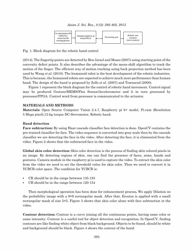
Fig. 1: Block diagram for the robotic hand control
(2014). The fingertip points are detected by Ben-Israel and Moses (2007) using starting point of theconvexity defect points. It also describes the advantage of the mean-shift algorithm to track themotion of the finger. The efficient way of motion tracking using back projection method has beenused by Wang et al. (2010). The humanoid robot is the best development of the robotic industries.This is because, the humanoid robots are expected to achieve much more performance than humanhand. The design of the hand is proposed by Zollo et al. (2007) and Townsend (2000).
Figure 1 represent the block diagram for the control of robotic hand movement. Control signalmay be produced Gesture/MEMS/Flex Sensor/Accelerometer and it in turn processed byprocessor/FPGA. Control word from processor is communicated to the actuator.
MATERIALS AND METHODSMaterials: Open Source Computer Vision 2.4.7, Raspberry pi b+ model, Pi-cam (Resolution5 Mega pixel),12-kg torque DC-Servomotor, Robotic hand.
Hand detectionFace subtraction: By using Haar cascade classifier face detection is done. OpenCV contains thepre-trained classifier for face. The video sequence is converted into gray scale then by the cascadeclassifier we are detecting the face in the video. After detecting the face, it is eliminated from thevideo. Figure 2 shows that the subtracted face in the video.
Global skin color detection: Skin color detection is the process of finding skin colored pixels inan image. By detecting regions of skin, one can find the presence of faces, arms, hands andgestures. Camera module in the raspberry pi is used to capture the video. To extract the skin colorfrom the video we need to set the threshold value for skin color. Then we need to convert it inYCBCR color space. The condition for YCBCR is:
C CR should be in the range between 135-183C CB should be in the range between 120-154
Then morphological operation has been done for enhancement process. We apply Dilation onthe probability image with a 9×9 rectangular mask. After that, Erosion is applied with a smallrectangular mask of size 5×5. Figure 3 shows that skin color alone with face subtraction in thevideo.
Contour detection: Contour is a curve joining all the continuous points, having same color orsame intensity. Contour is a useful tool for object detection and recognition. In OpenCV, findingcontours are like finding white object from black background. Objects to be found, should be whiteand background should be black. Figure 4 shows the contour of the hand.
393

Asian J. Sci. Res., 8 (3): 392-402, 2015
Fig. 2: Face subtraction
Fig. 3: Skin color detection
Fig. 4: Contour detection of the hand
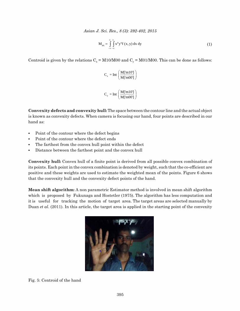
Centroid of the hand (Fig. 5): To find the centroid of the hand we are using image momentsfunction. Image moment will give the average of the image pixels intensities. For the 2D continuousfunction f (x, y) the moment is given by:
394
Asian J. Sci. Res., 8 (3): 392-402, 2015
(1)p qpqM x y f (x, y) dx dy
Centroid is given by the relations Cx = M10/M00 and Cy = M01/M00. This can be done as follows:
x
M['m10']C = Int
M['m00']
y
M['m10']C = Int
M['m00']
Convexity defects and convexity hull: The space between the contour line and the actual objectis known as convexity defects. When camera is focusing our hand, four points are described in ourhand as:
C Point of the contour where the defect beginsC Point of the contour where the defect endsC The farthest from the convex hull point within the defectC Distance between the farthest point and the convex hull
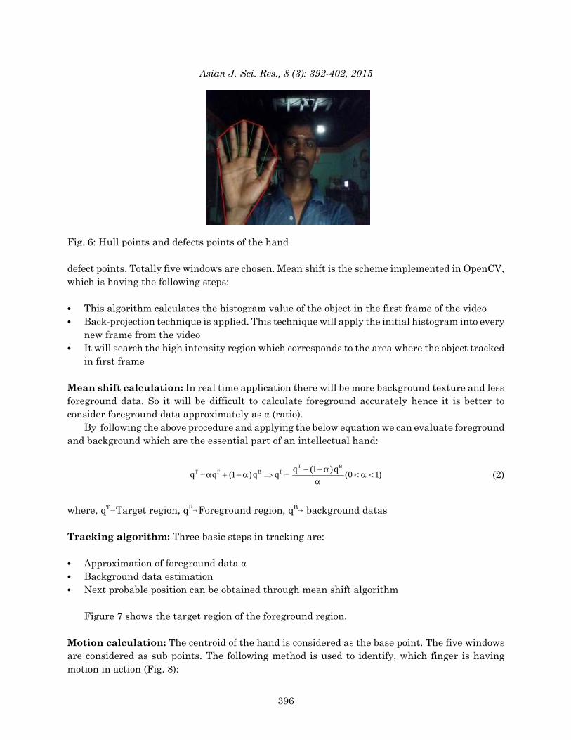
Convexity hull: Convex hull of a finite point is derived from all possible convex combination ofits points. Each point in the convex combination is denoted by weight, such that the co-efficient arepositive and these weights are used to estimate the weighted mean of the points. Figure 6 showsthat the convexity hull and the convexity defect points of the hand.
Mean shift algorithm: A non parametric Estimator method is involved in mean shift algorithmwhich is proposed by Fukunaga and Hostetler (1975). The algorithm has less computation andit is useful for tracking the motion of target area. The target areas are selected manually byDuan et al. (2011). In this article, the target area is applied in the starting point of the convexity
Fig. 5: Centroid of the hand
395
Asian J. Sci. Res., 8 (3): 392-402, 2015
Fig. 6: Hull points and defects points of the hand
defect points. Totally five windows are chosen. Mean shift is the scheme implemented in OpenCV,which is having the following steps:
C This algorithm calculates the histogram value of the object in the first frame of the videoC Back-projection technique is applied. This technique will apply the initial histogram into every
new frame from the videoC It will search the high intensity region which corresponds to the area where the object tracked
in first frame
Mean shift calculation: In real time application there will be more background texture and lessforeground data. So it will be difficult to calculate foreground accurately hence it is better toconsider foreground data approximately as α (ratio).
By following the above procedure and applying the below equation we can evaluate foregroundand background which are the essential part of an intellectual hand:
(2)T B
T F B F q (1 )qq q (1 )q q (0 1)
where, qT6Target region, qF6Foreground region, qB6 background datas
Tracking algorithm: Three basic steps in tracking are:
C Approximation of foreground data α C Background data estimationC Next probable position can be obtained through mean shift algorithm
Figure 7 shows the target region of the foreground region.
Motion calculation: The centroid of the hand is considered as the base point. The five windowsare considered as sub points. The following method is used to identify, which finger is havingmotion in action (Fig. 8):
396

Asian J. Sci. Res., 8 (3): 392-402, 2015
V Ip L p
H p
V h p
H hp
A
Ce n tr o id
Fig. 7: Image for mean shift algorithm
Fig. 8: Geometric relation finger tip and centroid
C (xc, yc)-centroid pointC (x0, y0)-line of intersection(lp) of principle axis and (0, y) line (implies)6(0, y0)C (x, y)-Hull point (hp)
Vertical distances:
Vhp = xc-x
Vlp = xc-x0, since, x0 = 0, Vlp = xc
Horizontal distances:
Hhp = yc-y
Hlp = yc-y0
Angle between principle axis and line joining Hull point (finger tip) and centroid of the palm, if Hlp and Vlp are negative or positive:
397
Asian J. Sci. Res., 8 (3): 392-402, 2015
Vhp VlpA = PI-atan -atan radians
Hhp Hlp
(Hlp and Vlp having opposite signs):
PI VhpA = -atan radians
2 Hhp
So, now we can find angle for five fingers. Now assemble the five angles in ascending order.Then we can able to identify the each finger separately.
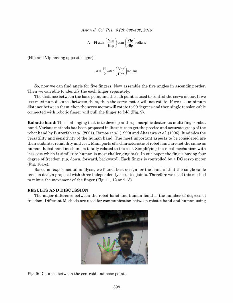
The distance between the base point and the sub point is used to control the servo motor. If weuse maximum distance between them, then the servo motor will not rotate. If we use minimumdistance between them, then the servo motor will rotate to 90 degrees and then single tension cableconnected with robotic finger will pull the finger to fold (Fig. 9).
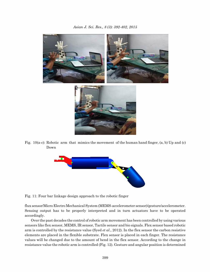
Robotic hand: The challenging task is to develop anthropomorphic dexterous multi-finger robothand. Various methods has been proposed in literature to get the precise and accurate grasp of therobot hand by Butterfab et al. (2001), Ramos et al. (1999) and Akazawa et al. (1996). It mimics theversatility and sensitivity of the human hand. The most important aspects to be considered aretheir stability, reliability and cost. Main parts of a characteristic of robot hand are not the same ashuman. Robot hand mechanism totally related to the cost. Simplifying the robot mechanism withless cost which is similar to human is most challenging task. In our paper the finger having fourdegree of freedom (up, down, forward, backward). Each finger is controlled by a DC servo motor(Fig. 10a-c).
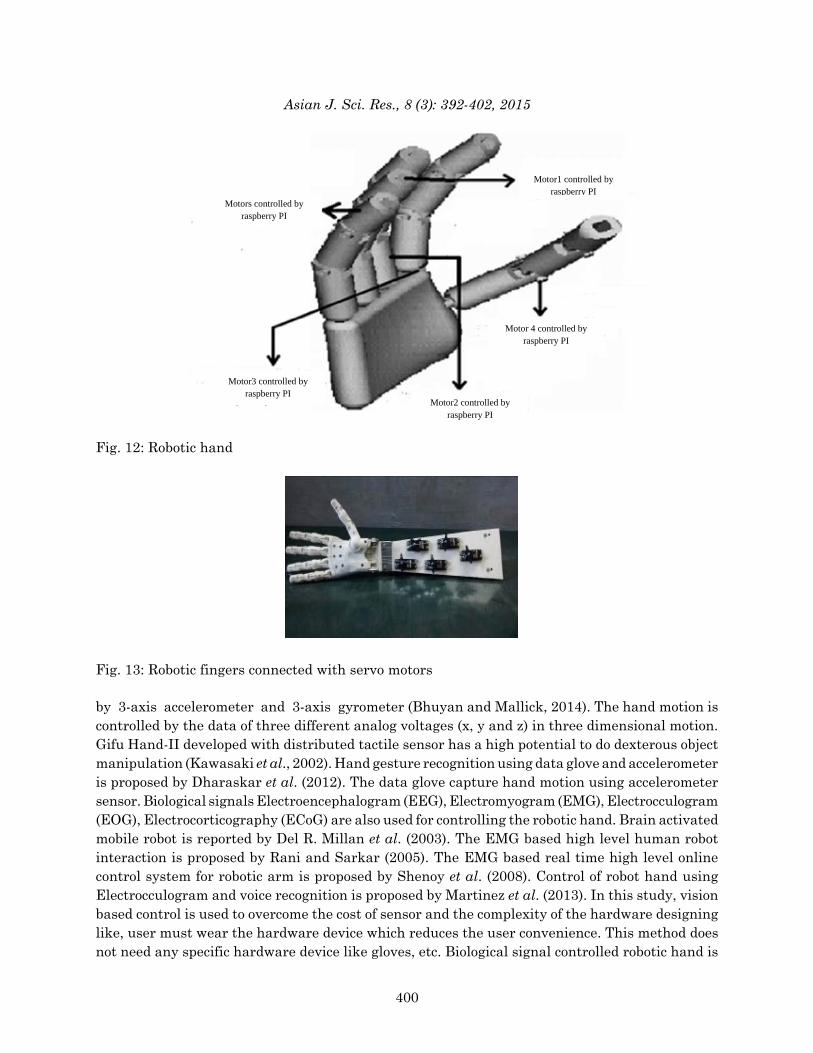
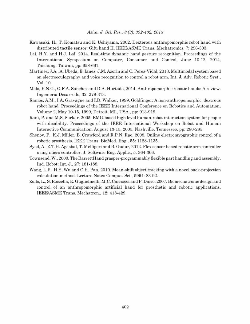
Based on experimental analysis, we found, best design for the hand is that the single cabletension design proposal with three independently actuated joints. Therefore we used this methodto mimic the movement of the finger (Fig. 11, 12 and 13).
RESULTS AND DISCUSSIONThe major difference between the robot hand and human hand is the number of degrees of
freedom. Different Methods are used for communication between robotic hand and human using
Fig. 9: Distance between the centroid and base points
398
Asian J. Sci. Res., 8 (3): 392-402, 2015
Fig. 10(a-c): Robotic arm that mimics the movement of the human hand finger, (a, b) Up and (c)Down
Fig. 11: Four bar linkage design approach to the robotic finger
flux sensor/Micro Electro Mechanical System (MEMS-accelerometer sensor)/gesture/accelerometer.Sensing output has to be properly interpreted and in turn actuators have to be operatedaccordingly.
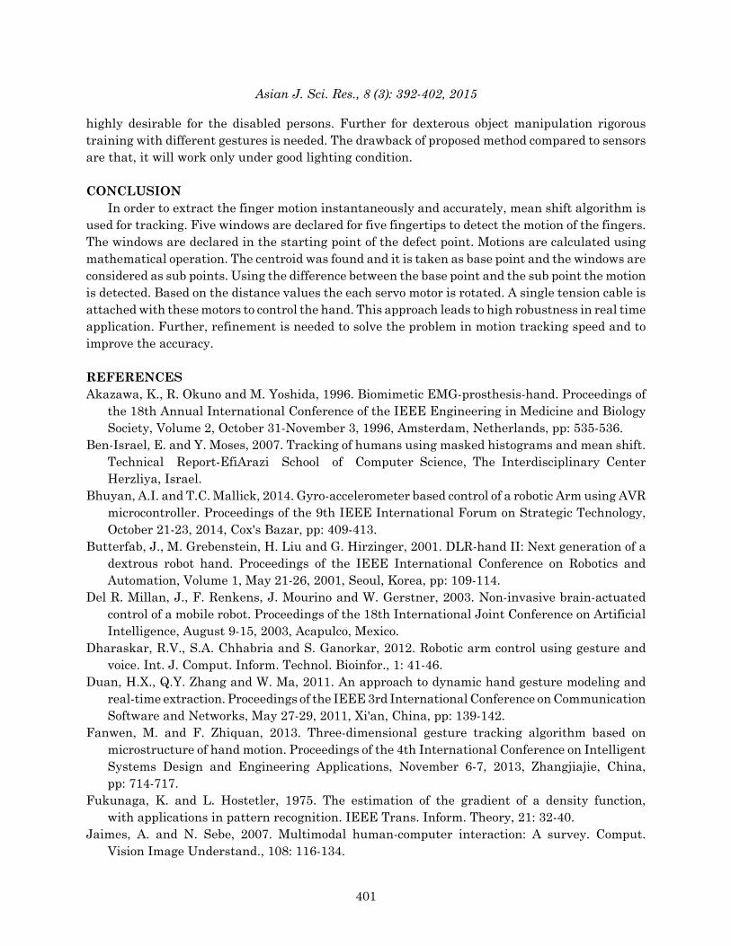
Over the past decades the control of robotic arm movement has been controlled by using varioussensors like flex sensor, MEMS, IR sensor, Tactile sensor and bio signals. Flex sensor based roboticarm is controlled by the resistance value (Syed et al., 2012). In the flex sensor the carbon resistiveelements are placed in the flexible substrate. Flex sensor is placed in each finger. The resistancevalues will be changed due to the amount of bend in the flex sensor. According to the change inresistance value the robotic arm is controlled (Fig. 12). Gesture and angular position is determined
399
(a) (b)
(c)
Asian J. Sci. Res., 8 (3): 392-402, 2015
Fig. 12: Robotic hand
Fig. 13: Robotic fingers connected with servo motors
by 3-axis accelerometer and 3-axis gyrometer (Bhuyan and Mallick, 2014). The hand motion is controlled by the data of three different analog voltages (x, y and z) in three dimensional motion.Gifu Hand-II developed with distributed tactile sensor has a high potential to do dexterous objectmanipulation (Kawasaki et al., 2002). Hand gesture recognition using data glove and accelerometeris proposed by Dharaskar et al. (2012). The data glove capture hand motion using accelerometersensor. Biological signals Electroencephalogram (EEG), Electromyogram (EMG), Electrocculogram(EOG), Electrocorticography (ECoG) are also used for controlling the robotic hand. Brain activatedmobile robot is reported by Del R. Millan et al. (2003). The EMG based high level human robotinteraction is proposed by Rani and Sarkar (2005). The EMG based real time high level onlinecontrol system for robotic arm is proposed by Shenoy et al. (2008). Control of robot hand usingElectrocculogram and voice recognition is proposed by Martinez et al. (2013). In this study, visionbased control is used to overcome the cost of sensor and the complexity of the hardware designinglike, user must wear the hardware device which reduces the user convenience. This method doesnot need any specific hardware device like gloves, etc. Biological signal controlled robotic hand is
400
Motors controlled by raspberry PI
Motor3 controlled by raspberry PI
Motor2 controlled by raspberry PI
Motor 4 controlled by raspberry PI
Motor1 controlled by raspberry PI
Asian J. Sci. Res., 8 (3): 392-402, 2015
highly desirable for the disabled persons. Further for dexterous object manipulation rigoroustraining with different gestures is needed. The drawback of proposed method compared to sensorsare that, it will work only under good lighting condition.
CONCLUSIONIn order to extract the finger motion instantaneously and accurately, mean shift algorithm is
used for tracking. Five windows are declared for five fingertips to detect the motion of the fingers.The windows are declared in the starting point of the defect point. Motions are calculated usingmathematical operation. The centroid was found and it is taken as base point and the windows areconsidered as sub points. Using the difference between the base point and the sub point the motionis detected. Based on the distance values the each servo motor is rotated. A single tension cable isattached with these motors to control the hand. This approach leads to high robustness in real timeapplication. Further, refinement is needed to solve the problem in motion tracking speed and toimprove the accuracy.
REFERENCESAkazawa, K., R. Okuno and M. Yoshida, 1996. Biomimetic EMG-prosthesis-hand. Proceedings of
the 18th Annual International Conference of the IEEE Engineering in Medicine and BiologySociety, Volume 2, October 31-November 3, 1996, Amsterdam, Netherlands, pp: 535-536.
Ben-Israel, E. and Y. Moses, 2007. Tracking of humans using masked histograms and mean shift.Technical Report-EfiArazi School of Computer Science, The Interdisciplinary CenterHerzliya, Israel.
Bhuyan, A.I. and T.C. Mallick, 2014. Gyro-accelerometer based control of a robotic Arm using AVRmicrocontroller. Proceedings of the 9th IEEE International Forum on Strategic Technology,October 21-23, 2014, Cox's Bazar, pp: 409-413.
Butterfab, J., M. Grebenstein, H. Liu and G. Hirzinger, 2001. DLR-hand II: Next generation of adextrous robot hand. Proceedings of the IEEE International Conference on Robotics andAutomation, Volume 1, May 21-26, 2001, Seoul, Korea, pp: 109-114.
Del R. Millan, J., F. Renkens, J. Mourino and W. Gerstner, 2003. Non-invasive brain-actuatedcontrol of a mobile robot. Proceedings of the 18th International Joint Conference on ArtificialIntelligence, August 9-15, 2003, Acapulco, Mexico.
Dharaskar, R.V., S.A. Chhabria and S. Ganorkar, 2012. Robotic arm control using gesture andvoice. Int. J. Comput. Inform. Technol. Bioinfor., 1: 41-46.
Duan, H.X., Q.Y. Zhang and W. Ma, 2011. An approach to dynamic hand gesture modeling andreal-time extraction. Proceedings of the IEEE 3rd International Conference on CommunicationSoftware and Networks, May 27-29, 2011, Xi'an, China, pp: 139-142.
Fanwen, M. and F. Zhiquan, 2013. Three-dimensional gesture tracking algorithm based onmicrostructure of hand motion. Proceedings of the 4th International Conference on IntelligentSystems Design and Engineering Applications, November 6-7, 2013, Zhangjiajie, China,pp: 714-717.
Fukunaga, K. and L. Hostetler, 1975. The estimation of the gradient of a density function,with applications in pattern recognition. IEEE Trans. Inform. Theory, 21: 32-40.
Jaimes, A. and N. Sebe, 2007. Multimodal human-computer interaction: A survey. Comput.Vision Image Understand., 108: 116-134.
401
Asian J. Sci. Res., 8 (3): 392-402, 2015
Kawasaki, H., T. Komatsu and K. Uchiyama, 2002. Dexterous anthropomorphic robot hand withdistributed tactile sensor: Gifu hand II. IEEE/ASME Trans. Mechatronics, 7: 296-303.
Lai, H.Y. and H.J. Lai, 2014. Real-time dynamic hand gesture recognition. Proceedings of theInternational Symposium on Computer, Consumer and Control, June 10-12, 2014,Taichung, Taiwan, pp: 658-661.
Martinez, J.A., A. Ubeda, E. Ianez, J.M. Azorin and C. Perez-Vidal, 2013. Multimodal system basedon electrooculography and voice recognition to control a robot arm. Int. J. Adv. Robotic Syst.,Vol. 10.
Melo, E.N.G., O.F.A. Sanchez and D.A. Hurtado, 2014. Anthropomorphic robotic hands: A review.Ingenieria Desarrollo, 32: 279-313.
Ramos, A.M., I.A. Gravagne and I.D. Walker, 1999. Goldfinger: A non-anthropomorphic, dextrousrobot hand. Proceedings of the IEEE International Conference on Robotics and Automation,Volume 2, May 10-15, 1999, Detroit, MI., USA., pp: 913-919.
Rani, P. and M.S. Sarkar, 2005. EMG-based high level human-robot interaction system for peoplewith disability. Proceedings of the IEEE International Workshop on Robot and HumanInteractive Communication, August 13-15, 2005, Nashville, Tennessee, pp: 280-285.
Shenoy, P., K.J. Miller, B. Crawford and R.P.N. Rao, 2008. Online electromyographic control of arobotic prosthesis. IEEE Trans. BioMed. Eng., 55: 1128-1135.
Syed, A., Z.T.H. Agasbal, T. Melligeri and B. Gudur, 2012. Flex sensor based robotic arm controllerusing micro controller. J. Software Eng. Applic., 5: 364-366.
Townsend, W., 2000. The BarrettHand grasper-programmably flexible part handling and assembly.Ind. Robot: Int. J., 27: 181-188.
Wang, L.F., H.Y. Wu and C.H. Pan, 2010. Mean-shift object tracking with a novel back-projectioncalculation method. Lecture Notes Comput. Sci., 5994: 83-92.
Zollo, L., S. Roccella, E. Guglielmelli, M.C. Carrozza and P. Dario, 2007. Biomechatronic design andcontrol of an anthropomorphic artificial hand for prosthetic and robotic applications.IEEE/ASME Trans. Mechatron., 12: 418-429.
402


![Index [assets.cambridge.org] · associated leuconorite, 402 associated quartz mangerite, 402 coarse grain size, 401, 402 composition of plagioclase, 402 crystal size distribution](https://static.fdocuments.us/doc/165x107/606c9147757c7d7d903e2249/index-associated-leuconorite-402-associated-quartz-mangerite-402-coarse-grain.jpg)