Asetek InRackCDU Installation, Operation & …...Asetek InRackCDU Installation, Operation &...
29
CA92344-3632-01 Installation, Operation & Maintenance Guide InRackCDU (4U-V2) Oct. 2019
Transcript of Asetek InRackCDU Installation, Operation & …...Asetek InRackCDU Installation, Operation &...

CA92344-3632-01
Installation, Operation & Maintenance Guide InRackCDU (4U-V2)
Oct. 2019

Asetek InRackCDU Installation, Operation & Maintenance Guide 1
Table of Contents
1. Product Introduction ............................................................................................................................ 2
1.1 CDU Cabinet ................................................................................................................................. 3
1.2 Coolant Distribution Manifold (CDM).......................................................................................... 4
1.3 Facilities Hoses ............................................................................................................................ 4
1.4 Server to CDM Tube Sets ............................................................................................................. 5
1.5 Coolant ........................................................................................................................................ 5
2 Important Information ......................................................................................................................... 6
3 Tools & Materials Required .................................................................................................................. 8
4 Unpacking the InRackCDU System ....................................................................................................... 8
5 Installation ............................................................................................................................................ 9
5.1 Mounting the CDU Cabinet ......................................................................................................... 9
5.2 Installing the Facility Hoses to the CDU Cabinet ......................................................................... 9
5.3 Mounting the CDMs to the Rack ............................................................................................... 10
5.4 Connecting CDU Cabinet to CDM .............................................................................................. 11
5.5 Mount Ventilation Tube for Reservoir ...................................................................................... 11
5.6 Connect Power and Networking to Monitoring System ........................................................... 12
5.7 Install 3rd Party External Leak Sensors (Optional(out of support by FUJITSU)) ......................... 12
5.8 Configure Monitoring System on Network ............................................................................... 14
6 System Startup ................................................................................................................................... 15
6.1 Preparation of floor for InRackCDU with for facility tubes connection in the bottom ............. 15
6.2 Connecting the InRackCDU System to Facilities Water ............................................................. 15
6.3 Connect Server Tube Sets to CDM ............................................................................................ 17
6.4 Powering Up Servers ................................................................................................................. 17
7 Routine Maintenance ......................................................................................................................... 18
7.1 Check Reservoir Level and Refill As Necessary .......................................................................... 18
7.2 Replacing Power Supplies .......................................................................................................... 19
8 Other Abnormalities and Failures ...................................................................................................... 20
Appendix I – Spill Response ........................................................................................................................ 20
Appendix II - CDU Specifications ................................................................................................................. 21
Appendix III – Facility Water Requirements ............................................................................................... 22
Appendix IV – Installation of InRackCDU in PCR-M2 rack ........................................................................... 24
Appendix V – Installation of Transportation Lock in PCR-M2 rack ............................................................. 26
Appendix VI – Thermal performance data .................................................................................................. 27

Asetek InRackCDU Installation, Operation & Maintenance Guide 2
1. Product Introduction
Asetek InRackCDU is a data center, warm water, direct-to-chip (D2C), liquid cooling system that is deployable at a rack level. The InRackCDU system consists of six major components:
1. CDU Cabinet containing liquid-to-liquid heat exchanger and coolant reservoir 2. CDU to CDM hoses 3. Coolant Distribution Manifolds (CDM) 4. Power supply for monitoring system 5. Facility hose pair (not shown) 6. Rail kit (not shown)
The first three components of the InRackCDU system are delivered pre-filled with server cooling liquid. There is no need for data center staff to handle server cooling liquid when installing the InRackCDU or when removing and replacing servers during maintenance. Tubes connect between the CDM and server coolers with locking dripless quick connectors. These connectors seal immediately when disconnected keeping the server coolant in the tube, CDM and server cooler.
Asetek InRackCDU Installation, Operation & Maintenance Guide 3
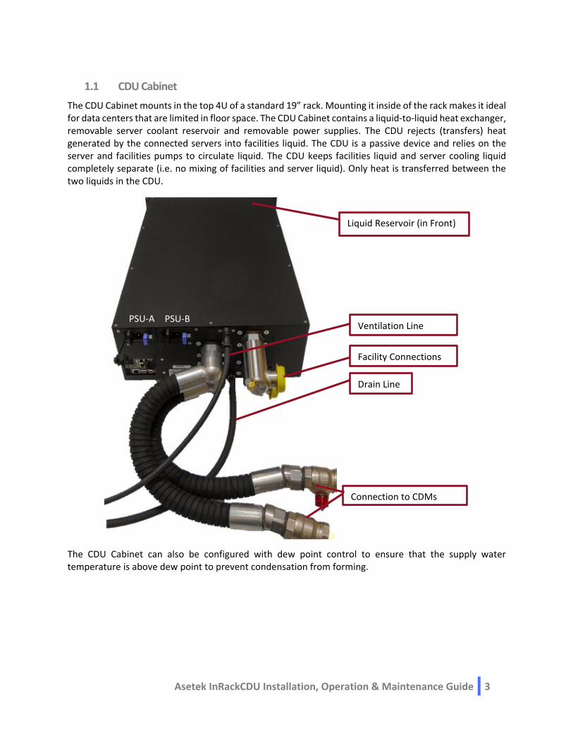
1.1 CDU Cabinet
The CDU Cabinet mounts in the top 4U of a standard 19” rack. Mounting it inside of the rack makes it ideal for data centers that are limited in floor space. The CDU Cabinet contains a liquid-to-liquid heat exchanger, removable server coolant reservoir and removable power supplies. The CDU rejects (transfers) heat generated by the connected servers into facilities liquid. The CDU is a passive device and relies on the server and facilities pumps to circulate liquid. The CDU keeps facilities liquid and server cooling liquid completely separate (i.e. no mixing of facilities and server liquid). Only heat is transferred between the two liquids in the CDU.
The CDU Cabinet can also be configured with dew point control to ensure that the supply water temperature is above dew point to prevent condensation from forming.
Connection to CDMs
Facility Connections
Ventilation Line
Liquid Reservoir (in Front)
Drain Line
PSU-B PSU-A

Asetek InRackCDU Installation, Operation & Maintenance Guide 4
The CDU Cabinet also comes with a monitoring system that monitors the following.
Facility liquid temperature – Supply & Return
Server liquid temperature – Supply & Return
Facility liquid pressure
Facility liquid flow rate
Server liquid pressure
Coolant reservoir level
Heat load
Leak detection (inside cabinet)
Dew point control (optional)
The monitoring system is capable of sending out email alerts and alarms at user-defined thresholds and communicates to with DCiM (Data Center Infrastructure Management) or DCM (Data Center Management) systems via SNMP.
1.2 Coolant Distribution Manifold (CDM)
The CDMs mount like zero-U PDUs in the space at the hot aisle end of the rack. CDMs are delivered in pairs, one supply (cold, with blue quick connectors) and one return (hot, with red quick connectors). CDMs deliver cool coolant from the CDU cabinet to the server liquid coolers and return heated coolant from the server coolers to the CDU cabinet.
1.3 Facilities Hoses
Facilities hoses connect the CDU cabinet to the facilities water system. This system may be located under a raised floor or above the rack, typically above the hot aisle. Connection to the facilities liquid system is made via Camlock fittings. Camlock fittings are a globally-available, tool-less connection system where the dimensions of the matting ends are governed by international standards, allowing a male Camlock purchase on one continent to mate seamlessly with a female Camlock purchased on another continent.

Asetek InRackCDU Installation, Operation & Maintenance Guide 5
1.4 Server to CDM Tube Sets
The CDMs are connected to the server liquid coolers via pairs of connecting tubes. One tube is used to deliver cooled (supply) liquid to the server. The other returns heated (return) liquid from the servers to the heat exchangers for heat rejection into facilities liquid.
1.5 Coolant
The server coolant in InRackCDU systems is a mixture of DI water, propylene glycol with some additional additives for corrosion resistance. It is a safe, environmentally friendly liquid. It provides freeze protection and inhibits corrosion and biological growth within the system. The coolant is not a “Hazardous Chemical” as defined by the OSHA Hazard Communication Standard, 29 CFR 1910.1200. A Material Safety Data Sheet (MSDS) for the coolant is included in the packaging.

Asetek InRackCDU Installation, Operation & Maintenance Guide 6
2 Important Information Any failure to observe the guidelines in this manual, and any improper repairs could expose the
user to risks (electric shock, energy hazards and fire hazards) or damage the equipment.
If the CDU Cabinet enclosure has been moved from a cold environment, into a warm data center condensation may form both inside and on the outside of the machine.
Wait until the CDU Cabinet has acclimatized to room temperature and is absolutely dry before starting it up. Material damage may be caused to the monitoring system if this requirement is not met.
Only transport the InRackCDU and CDMs in the original packaging or in packaging that protects it from impacts and jolts.
The monitoring unit in the CDU Cabinet requires a supply voltage of 100 – 240 V 50/60 Hz. There are two redundant, hot-swappable power supplies.
This device must only be connected to properly grounded power outlets or insulated sockets of the rack's internal power supply with tested and approved power cords.
Never connect or disconnect data transmission lines during a storm (risk of lightning hazard).
Make sure that no objects (e.g. jewelry, paperclips etc.) or liquids can get inside the CDU cabinet (risk of electric shock, short circuit).
In emergencies (e.g. damaged casing, controls or cables, penetration of liquids or foreign bodies), switch off the server enclosure immediately, remove all power plugs and contact your sales outlet or customer service team.
In the unlikely event of a spill or leak of coolant from the server liquid loop follow the suggested spill response procedure listed in Appendix I.
The circuit boards and soldered parts of internal options are exposed and can be damaged by static electricity. Before handling them, first touch a metal part of the CDU cabinet to discharge static electricity from your body.
Do not touch the circuitry on boards or soldered parts. Hold the edges of the circuit boards.
For CDU Cabinet installation use a server lift.
Asetek InRackCDU Installation, Operation & Maintenance Guide 7
This manual is for Service, Factory and Customer. For products shipped from Fujitsu, the division of labor described in each section is as follows.
section division
4. Unpacking the InRackCDU System Factory
5. Installation 5.1 Mounting the CDU Cabinet Factory
5.2 Installing the Facility Hoses to the CDU Cabinet Factory
5.3 Mounting the CDMs to the Rack Factory
5.4 Connecting CDU Cabinet to CDM Factory
5.5 Mount Ventilation Tube for Reservoir
Ventilation Tube Service
Drain Tube Customer
5.6 Connect Power and Networking to Monitoring System Service
5.7 Install 3rd Party External Leak Sensors Customer
5.8 Configure Monitoring System on Network
Default static IP address & subnet mask Customer
Recommended Setting of Monitoring System Customer
Status Service
6. System Startup Customer
7. Routine Maintenance Service
8. Other Abnormalities and Failures # Customer # In case of any other Abnormalities and Failures, the CDU cabinet or CDM will be replaced, and Service-Task will be changed to special care. Please contact your supplier.
The InRackCDU system ships out from the factory in a rack.
When the customer orders the InRackCDU system and LC Server at the same time, the water-cooled tubes that connect the InRackCDU system and LC Server are connected by the factory.

Asetek InRackCDU Installation, Operation & Maintenance Guide 8
3 Tools & Materials Required
The following tools and supplies are needed to unpack and install the InRackCDU System:
Tool Usage Prepared by
Screwdriver with Phillips #2 to install CDU cabinet and CDM into Rack Factory
Tin Snips to open packing box Factory
Box Cutter or Utility knife to open packing box Factory
8mm open-end wrench to install CDM to Rack Factory
22mm open-end wrench to open fillcap of reservoir tank. Service
Bucket to make ventilation of Facility Water Customer
Funnel(end size is 18mm or less) to fulfill reservoir with coolant Customer
Network Cross cable (RJ45 to RJ45) min. 2m in length
to startup monitoring system Service & Customer
Laptop with wired network port to set up network addresses in monitoring system
Service
Server lift to raise and install CDU cabinet into rack Factory
Wet and Dry vacuum cleaner to remove water on floor in case of leakage Customer
O-ring To replace in case of filling coolant to reservoir tank
Customer# Service #
# 10pcs. of O-rings are attached CDU cabinet as accessory, and customers keep them. In case of that 10pcs. finish or customer lost, Service must be order as spare parts.
4 Unpacking the InRackCDU System
WARNING: Removing and installing the CDU Cabinet and CDM is at minimum a three-person job. The CDU Cabinet weighs 80kg and needs to be lifted to the top U-space in the rack. It is recommended that installers use a lift to get the cabinet into the rack
1. The CDU Cabinet and CDMs will arrive in several boxes atop a wooden pallet packed in a cardboard
shipping carton. The weight and dimensions (LxWxH) are: a. HEX Cabinet: 80kg, 116cm x 75cm x 27cm (3’ 9.6” x 2’ 5.5” x 10.6”) b. CDM Pair (42U): 15kg, 180cm x 18cm x 16cm (5’ 10.9” x 7.1” x 6.3”) c. CDM Pair (48U): 17kg, 224cm x 25cm x 13cm (7’ 4.2” x 9.2” x 5.1”)
2. Cut the strapping that holds the cardboard shipping carton to the pallet with the tin snips. 3. Lift the cardboard carton lid off of the HEX Cabinet and CDMs and remove any packing foam inserts. 4. Care should be taken to remove the HEX Cabinet from the crate as it weighs approximately 80kg.
Two or more people are needed to lift the HEX Cabinet vertically from its packaging. 5. Move the HEX Cabinet and CDM clear of the pallet and set on a raised surface. 6. Be careful not to damage the drain tube exiting the rear of the CDU Cabinet.
Asetek InRackCDU Installation, Operation & Maintenance Guide 9
5 Installation
IMPORTANT: Do not power on server nodes at this point. Section 6 – System Startup, will outline when servers should be powered on.
5.1 Mounting the CDU Cabinet
Mount the rails 4U spaces down from the top of the rack (i.e. U39 in a 42U rack or U45 in a 48U rack). Ensure that rails are rated to support at least 80kg of weight. The CDU Cabinet weighs approximately 80kg (~180lbs) and a server lift should be used to lift and place inside of the rack.
The screws that are pressed into the CDU Cabinet are M5. Install an M5 cage nut into the rack.
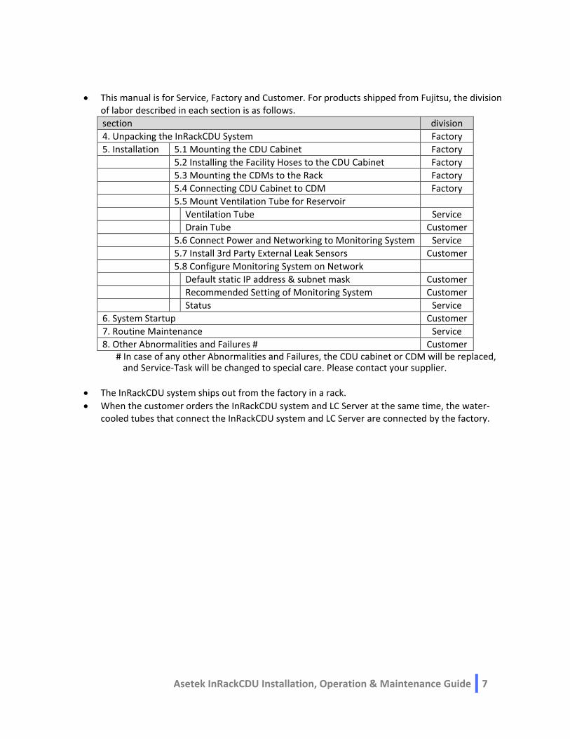
5.2 Installing the Facility Hoses to the CDU Cabinet
Facility tube connections are available on the rear right side of the CDU Cabinet. The facility liquid supply and return lines are marked with an “S” and “R”, respectively. The supply hose will have a female Camlock and the return hose will have a male Camlock.
Remove the protection caps from the return and supply connections. Insert the provided EPDM gasket between the flanges and install the tri-clamp locking ring.
For bottom feed connections, the minimum size opening that needs to be cut in the floor tile is 150mm x 150mm.
Important: For rack widths 700mm, install the pipe adapter in between the facility pipe connection on the CDU and facility hose.
Pipe adapter

Asetek InRackCDU Installation, Operation & Maintenance Guide 10
5.3 Mounting the CDMs to the Rack
Important: Do not use the Quick Connectors on the CDM as supports while mounting the CDM into the rack.
For the Fujitsu solution with Vertiv rack the CDM bracket has to be installed first see Appendix IV
The CDM is hung in the rack with mounting studs that are installed on the rear of the CDMs. Line up the mounting studs with the available key holes in the PDU hanging bracket and lower into place.
The return CDM (red quick connectors) is hung further into the rack and the supply CDM (blue quick connectors) is hung closer to the rear door.
The mounting studs can be adjusted as necessary so that the hose from the CDU cabinet to CDM is aligned.
The CDM(s) on Fujitsu Vertiv Rack are locked in position as described in Appendix V.
CDM(s) on other type of racks are locked into position by installing CDM locking bracket in below steps:
1. Install the CDM locking bracket with its 2 screw on top of the supply CDM (blue quick connectors)
2. Slide the 2 cable ties into the slot in the CDM locking bracket
3. Place the CDM inside the rack without hanging it on the CDM Holder 4. Rout the cable tie into a slot in the CDM bracket as below picture 5. Hang the CDM into the CDM bracket 6. Tighten the cable ties.
CDM lock
Cable tie
Cable tie

Asetek InRackCDU Installation, Operation & Maintenance Guide 11
5.4 Connecting CDU Cabinet to CDM
The two CDM hoses are fixed to the CDU Cabinet. The top hose connects to the supply CDM (blue) while the lower hose connects to the return CDM (red). Place the provided EPDM gasket between the flanges on the hose and the CDM and install the Tri Clamp locking ring.
5.5 Mount Ventilation Tube for Reservoir
To secure atmospheric pressure, a venting tube must be mounted to the Quick Connector on the rear side of the CDU cabinet. Remove the protection caps from the quick connector and ventilation tube, then mount the tube as shown below.
The ventilation tube must be disconnected during transportation and should only be mounted at finale location. When connection is complete, route the ventilation tube and the drain tube inside the rack down to the floor.
If there is a water leak in the CDU cabinet, the drain will drain from the end of the drain tube. Please prepare the drainage facilities at the facility side.
Attach venting tube
Drain tube

Asetek InRackCDU Installation, Operation & Maintenance Guide 12
5.6 Connect Power and Networking to Monitoring System
The connection points for power and network are located on the left rear side of the cabinet as shown below.
The monitoring system requires a supply voltage of 100 - 240V, 50/60Hz. The power inlet on the two, redundant, hot-swappable power supplies in cabinet is a C14 male and requires a power cord with a C13 connector. The power cable is customer supplied to match the sockets on the power distribution units (PDU) of the rack. After connecting the power cord, secure it with the cable relief.
To add the monitoring system to a network, connect a shielded F/UTP network cable with shielded RJ45 connectors to the port at the top left of the monitoring system box.
5.7 Install 3rd Party External Leak Sensors (Optional(out of support by FUJITSU))
Up to two optional 3rd party external leak sensors can be connected to the CDU Cabinet. These external leak sensors must have one of the following types of output:
An open collector output
A relay output which connects the output to ground.
A digital high/low signal, with a high voltage between 3V and 5V.
The sensor output must be active low when the sensor is DRY. The output must be high or open when sensor is wet. Sensors with analog output cannot be used.
There is a 12V DC supply available for the sensor. Each sensor port can deliver max 150mA.
The external sensors are connected to the monitoring box as shown on the picture below.
Network connection
Power connection
C13 Connector
External sensor #2
External sensor #1

Asetek InRackCDU Installation, Operation & Maintenance Guide 13
The external leak sensor #1 connects to the white port in the upper left corner and external leak sensor #2 connects to the red port in the upper right corner.
Pin layout for connection cable between external leak sensor and monitoring box is shown below:
White: External Leak Sensor #1 Red: External Leak Sensor #2
GND P1 P1
Sense Input P4 P5
12V Out P6 P6
Contact Asetek to learn more about 3rd party leak detection solutions.
Asetek InRackCDU Installation, Operation & Maintenance Guide 14
5.8 Configure Monitoring System on Network
Default static IP address & subnet mask
IP address: 192.168.0.199 Gateway: 192.168.0.1 Subnet mask: 255.255.255.0
Configure the laptop to use the same subnet mask and gateway and an address in the subnet besides 199 and point a web browser at the IP address above. You will be asked for a user name and password. Two levels of user name and password are provided: Standard Users and Administrators. Only Administrators may change the network settings on the monitoring system. To log onto the monitoring system as an administrator:
Username: Admin Password: admin
Under the “Settings” heading on the left you will see a “Network” button. Select the Network button and then de-select the DHCP: check box and enter the desired IP address, default gateway and subnet masks.
Additional information on the monitoring system is provided in the monitoring manual.
Recommended Setting of Monitoring System
Refering the leaflet of the InRackCDU system ”Recoomended Setting of Monitoring System”, please define to setting values of Monitoring System.
Additional information on the monitoring system is provided in the monitoring manual.
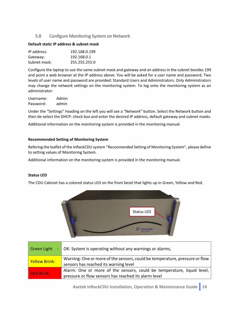
Status LED
The CDU Cabinet has a colored status LED on the front bezel that lights up in Green, Yellow and Red.
Green Light : OK: System is operating without any warnings or alarms,
Yellow Brink: Warning: One or more of the sensors, could be temperature, pressure or flow sensors has reached its warning level
Red Brink: Alarm: One or more of the sensors, could be temperature, liquid level, pressure or flow sensors has reached its alarm level
Status LED

Asetek InRackCDU Installation, Operation & Maintenance Guide 15
6 System Startup
6.1 Preparation of floor for InRackCDU with for facility tubes connection in the bottom
The flooring for InRackCDU with facility connection from the bottom must be prepared with a 100x150mm opening for routing of the facility hoses from underneath the floor to the InRackCDU inside the rack as below example.
6.2 Connecting the InRackCDU System to Facilities Water
The facility water line should be prepared with male and female camlock connectors as shown below. Water flows from the male camlock into the female camlock. Connect the cam locks by bringing the two ends together and then pull back the handles on the female connector as shown in the second picture.
150mm
100mm

Asetek InRackCDU Installation, Operation & Maintenance Guide 16
For Bottom Fed Facility Line Only - Connect both facility hoses (supply & return) to the facility water line and install the Schrader bleed kit onto the Schrader valve on the supply side. Open all the valves including the circuit setter valve and let water flow through the CDU cabinet. With someone holding the end of the bleed kit into a bucket, slowly open the Schrader valve to help bleed the air out of the system. Once there is a steady stream of water flowing out, close the Schrader valve. Check the monitoring system to insure there is facilities liquid flow to the rack.
The facility supply hose is also fitted with a pressure release valve which can be used to relieve the facility pressure release before disconnecting the facility hoses by following the steps below:
Shut down all of the servers in the rack.
Close all shut off valves on facility hoses and facility side.
Position a small container underneath the pressure release valve of the supply hose.
Open pressure release valve and keep it open until the liquid flow out of the release valve stops.
Close the pressure release valve and disconnect facility hoses.
Schrader bleed kit

Asetek InRackCDU Installation, Operation & Maintenance Guide 17
6.3 Connect Server Tube Sets to CDM
The tube sets, and connectors are color coded to simplify connecting the server coolers to the CDM. The supply tubes are marked with a blue ring, while the return tubes are marked with a red ring. They connect to the corresponding color-coded vertical row of connectors on the CDM.
To connect individual servers to the CDM, follow the steps in the picture to the right.
To disconnect the tube from the CDM, push the tube connectors toward the CDM (about 1/8th inch) and twist the connector counterclockwise until it stops. The tube connector will be pushed off the CDM connector by the springs inside.
6.4 Powering Up Servers
IMPORTANT: This procedure is only required when the rack is powered on for the first time in the factory. It is critical to closely follow the instructions below to get any residual air out of the system.
Server coolers connect to the CDM via sets of connecting tubes. These tube sets are factory filled and sealed with coolant. However, a small amount of air remains in the tubes and in the server coolers. While the amount is small on an individual tube and server cooler basis, if the air in all the server coolers and tubes is introduced into the CDU Cabinet at once, it can cause problems. To avoid these problems, follow the steps below:
1. Servers are connected and turned on in IDLE mode from the bottom, 6U slots at a time 2. Let the above 6U servers run for 3-5 minutes. 3. Repeat Steps #1-2 for the next 6U slot servers. 4. Once all servers are powered on, let the entire rack run in idle mode for another 60 minutes. 5. Repeat above steps an eventual 2nd set of CDM’s
This process gradually introduces air into the system at a speed that allows the normal venting process to clear the air from the InRackCDU System.
Once this initial process has been completed, all the servers may be powered off and on simultaneously. This row-by-row power on sequence only needs to be followed the first time all servers are connected to the InRackCDU System.

Asetek InRackCDU Installation, Operation & Maintenance Guide 18
7 Routine Maintenance
There is a reservoir in the 4u InRackCDU cabinet. As the liquid cooling system runs, liquid gradually permeates through the rubber tubing and plastic parts in the system. The reservoir contains sufficient fluid to replenish the liquid that permeates out of the system for more than 50,000 hours of 24/7/365 operation. The RackCDU monitoring system will alert you when the fluid in the reservoir reaches a low point. I
When a low coolant alert is received additional coolant may be added to the reservoir via a fill port at the top of the RackCDU. The RackCDU must be filled with manufacturer provided server coolant. Using water or other types of coolant will damage the server cooling system!
7.1 Check Reservoir Level and Refill As Necessary
The reservoir is located behind the front panel on the CDU cabinet. To access the reservoir, remove the
front of the CDU cabinet and push/lift and swing out the lever. The reservoir will eject out of the cabinet.
Unscrew the plug with a 22mm wrench from the fill port and apply cooling liquid with a small funnel
until the liquid level is 1 cm (0.5 in) from the top of the opening. Keep the reservoir in an upright
position when refilling to prevent spilling.
Reservoir
Reservoir Locking Lever
Front panel

Asetek InRackCDU Installation, Operation & Maintenance Guide 19
Before screwing the plug back into the reservoir, replace the black O-ring on the plug. Replacement O-rings (Asetek PN P00004415) are included on the zipper bag on the below picture and can be purchased from Asetek. Please keep O-rings by customer for preparing that servicemen will use and replace O-ring.
Reinstall reservoir back into the HEX Cabinet, lever and front panel on the CDU cabinet.
7.2 Replacing Power Supplies
The 4u InRackCDU V2 Power Supplies are redundant and designed for hot-swap, tool-less installation. Each power supply has a status LED which will light up in green when the power supplier is operating without problems and be turned off in case of a problem with the power supply.
Follow below steps to replace a power supply:
Disconnect power cable from the PSU up for replacement
Pres the PSU latch to the right while pulling on handle of PSU to remove the hot power supply from chassis.
Insert new hot swap power supply and ensure that the PSU latch locks into position.
Connect power cable and verify that the PSU LED light up in green.
PSU latch PSU handle
PSU-A PSU-B

Asetek InRackCDU Installation, Operation & Maintenance Guide 20
8 Other Abnormalities and Failures
In case of any other Abnormalities and Failures, the CDU cabinet or CDM will be replaced, so please contact your supplier.
Appendix I – Spill Response
In case of spill of server coolant
Server coolant is an electrically conductive liquid: LOOK FIRST FOR ANY POTENTIAL CONTACT BETWEEN THE LIQUID AND POWER CONNECTORS. AVOID CONTACT WITH COOLANT IF A POTENTIAL FOR ELECTRICAL SHOCK DUE TO COOLANT WETTING POWER CONNECTORS IS OBSERVED until power is turned off to the wet connectors!
Eye/Face Protection
Server coolant may cause slight temporary eye irritation. Use safety glasses (with side shields) to prevent any accidental eye contact with liquid. If eye contact occurs, immediately flush with plenty of water. Get to medical attention, if any discomfort continues.
Skin Protection
Prolonged contact is essentially nonirritating to skin. However, hand protection is recommended in the form of gloves chemically resistant to the material including gloves with barrier materials of Butyl rubber, Natural rubber ("latex"), Neoprene, Nitrile/butadiene rubber ("nitrile" or "NBR"), Polyethylene, Ethyl vinyl alcohol laminate ("EVAL"), Polyvinyl alcohol ("PVA"), or Polyvinyl chloride ("PVC" or "vinyl"). If gloves are not worn, wash hands with plenty of water following clean up.
Small Spills
Small spills of less than a cup may be cleaned up with towels or other absorbent materials. Absorb the spilled liquid and wring into bucket. Fill bucket with tap water and pour into sink drain. Refill bucket and rinse towels. Empty bucket and wring towels. Fill bucket half full then return to spill area and rinse area with towels and clean water, wringing rinse water back into bucket. Dump this rinse water into a sink drain and wring towels. Allow cloth towels to dry and then wash. Dry and incinerate paper towels. Flush bucket with plenty of fresh water to clean.
Moderate Spills
For spills were enough liquid is present to collect a reasonable amount in a container, liquid may be collected with a clean wet/dry vacuum or it may be collected with towels or other absorbent material and wrung into a bucket. Collected liquid should be transferred to a sealable container and this container should be sealed and marked as containing “Enhanced Propylene Glycol”. Dispose of waste and residues in accordance with local authority requirements. (Collected liquid may be disposed of by taking to a

Asetek InRackCDU Installation, Operation & Maintenance Guide 21
recycling center for glycol or anti-freeze. Alternatively, they may be disposed of in an incinerator or other thermal destruction device.) Do not dump quantities over 1quart into any sewers on the ground or into any body of water! Dilute any quantities less than 1 quart by at least 5 to 1 before dumping into sanitary sewers.
After collecting the spill, return to the spill area with half a bucket of fresh water and rinse area with towels and clean water, wringing rinse water back into bucket. Dump this rinse water into a sink drain and wring towels. Allow cloth towels dry and then wash. Dry and incinerate paper towels. Flush liquid collection equipment with plenty of fresh water to clean.
Appendix II - CDU Specifications Parameter Specification
Dimension (L x W x H) 73.7cm x 44.4cm x 17.8cm (length is just for cabinet without hoses)
Weight, including coolant CDU Cabinet: 80kg (176.4lbs) CDM (pair): 42U: 10kg (22.0lbs) 48U: 12kg (26.5lbs),
Facility Water Pressure Max: 8.62 bar (125 PSI)
Facility Flow Rate 1¼ inch facility hose: Max 5200 l/h (23 GPM) 1½ inch facility hose: Max 7900 l/h (35 GPM) Cooling capacity is influenced by facility flow rate, max cooling capacity is obtained with max facility flow
Electrical Requirements Power Supply Voltage: 100VAC to 240VAC, 50/60Hz, auto-range Connector: IEC320 C14 (male) Power Consumption: 70W Max, 15W Normal Operation
Electrical Requirements Physical Layer: Copper wire, RJ-45 Connector Application Layer: Web browser interface, SNMP, e-mail alerts & alarms

Asetek InRackCDU Installation, Operation & Maintenance Guide 22
Appendix III – Facility Water Requirements
General Requirements
Parameter Specification
Facilities Supply Water Temperatures for 4u InRackCDU with dew point control
Max: 45°C (113°F) Min: 2°C (5°F) above freezing temperature
Facilities Supply Water Temperatures for 4u InRackCDU without dew point control
Max: 45°C (113°F) Min: 2°C (5°F) above the higher of freezing or dew point temperature
Facilities Return Water Temperatures
Max: 60°C (140°F) Min: 2°C (5°F) above the higher of freezing or dew point
Material Requirements, Facilities Side
ASHRAE D-90564, 5.1.2.5 Wetted Materials Requirements
Particulates Facilities liquid shall be clear of particulate matter greater than 0.84mm in any dimension.
Corrosion Inhibition Compatible with wetted materials in CDU cabinet: • Copper • Brass • Stainless Steel
Pressure drop across the InRackCDU facility side

Asetek InRackCDU Installation, Operation & Maintenance Guide 23
Facilities Water Quality Requirements:
The requirements for the facilities loop are site specific and generally beyond the scope of this document, however, the facilities loop must utilize cooling water that meets or exceeds the water quality standards in ASHRAE’s Liquid Cooling Guidelines for Datacom Equipment Centers, Third Edition, herein after “ASHRAE D-90564” and some additional requirements.
Parameter Value Incl. in ASHRAE D-90564
pH 7 to 9 Yes
Corrosion Inhibitor(s) Required Yes
Sulfides <10 ppm Yes
Sulfate <100 ppm Yes
Chloride <50 ppm Yes
Bacteria < 1000 CFUs / ml Yes
Total Hardness <200 ppm (as CaCO3) Yes
Residue After Evaporation <500 ppm Yes
Turbidity <20 NTU (Nephelometric) Yes
Glycol concentration Max 38% Yes
Total Hardness < 100mg/L. Calcium (Ca) and Magnesium (Mg)
Total Organic Carbon (TOC) <25 mg/L
Suspended Solids (SS) <25 mg/L
Iron (Fe) <10 mg/L

Asetek InRackCDU Installation, Operation & Maintenance Guide 24
Appendix IV – Installation of InRackCDU in PCR-M2 rack Important: Do not power on server node until installation is completed. In addition, perform the installation and powering up in the sequence described in Chapter”6.4 Powering Up Servers” the first time the rack is powered on after installation in the factory.
Vertiv Rack isEMEA market, and CEC Rack is no EMEA market(US, JP, APAC, etc).
The CDM-holder kit is installed in the rack on the rear side as shown below.
Fig: 1PCR-M2 Rack with CDM-Holder (PDU BRACKET DCM RACK H2000)
Fig: RackCDU with CDM in rear only
CDM-Holder Kit
A3C40195628
197m
m
CDM-Holder
P/N: A3C40196331
36m
m
53m
m

Asetek InRackCDU Installation, Operation & Maintenance Guide 25
The CDM hangs inside the rack in the CDM bracket. Install the CDM bracket by following below steps.
1. Installation of the spring nuts into the profile
2. Installation of the CDM-Bracket (Torque of the screws = 5,2Nm)
Installation of the CDM-Holder (Torque of the nuts = 5,2Nm)
Spring Nut M6
P/N: A3C40133889
Nut M5
P/N: A3C40133896
Spring Nut M6
P/N: A3C40133889
PDU-Bracket
P/N: A3C40196332
Screw M6x12 / TX30
P/N: A3C40127330
CDM-Holder
P/N: A3C40196331
Bottom view Top view
Position Vertiv
Position CEC
Position Vertiv
Position CEC
Top view Bottom view

Asetek InRackCDU Installation, Operation & Maintenance Guide 26
Appendix V – Installation of Transportation Lock in PCR-M2 rack
Vertiv Rack is EMEA market and CEC Rack is for no EMEA market(US, JP, APAC, etc).
Installation of the transportation lock (Torque of the screws = 5,2Nm)
Mounting position of spring nuts
Position Vertiv
Position CEC
Position CEC Position Vertiv
Spring Nut M6
P/N: A3C40133889
Screw M6x12 / TX30
P/N: A3C40127330
Asetek InRackCDU Installation, Operation & Maintenance Guide 27
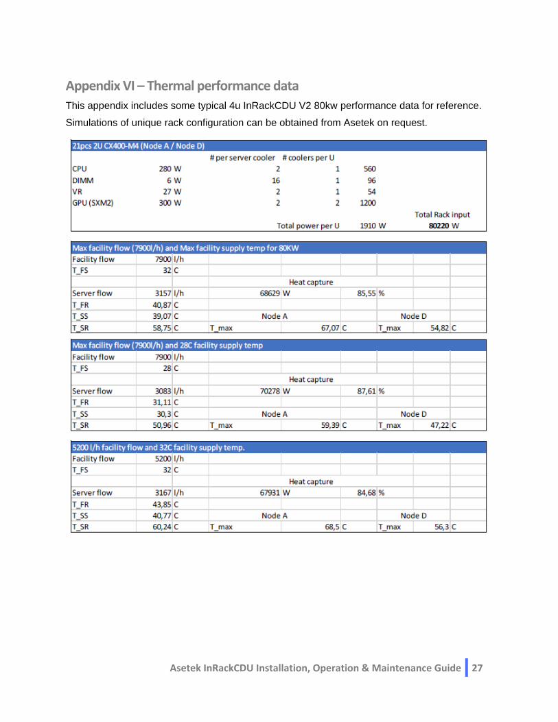
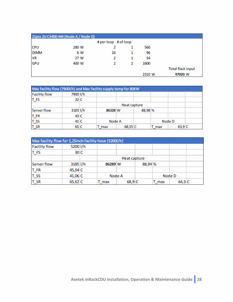
Appendix VI – Thermal performance data
This appendix includes some typical 4u InRackCDU V2 80kw performance data for reference.
Simulations of unique rack configuration can be obtained from Asetek on request.
Asetek InRackCDU Installation, Operation & Maintenance Guide 28