ASEP NSCP SECTION 207 WIND LOADS part 1.pdf
38
8/14/2013 1 WIND LOADS ON BUILDINGS IN ACCORDANCE WITH NSCP 2010 SECTION 207 Lecturer ENGR. ADAM C. ABINALES, M.ENG, F.ASEP Course STRUCTURAL ENGINEERING Introduction/Course Description Introduction One of the major and significant revisions of the NSCP Vol. I Sixth Edition 2010 is Chapter 2 which stipulates provisions on the minimum design loads to be applied on buildings, towers and other vertical structures. Section 207 of the NSCP Vol. I Sixth Edition2010 which discusses the wind load provisions of Chapter 2 Minimum Design Requirements is one of the major and significant changes. Wind load provisions of the NSCP Vol. I 2010 are generally referenced from the wind load criteria of the American Society of Civil Engineers (ASCE) publication, SEI/ASCE Standard 7-05, Minimum Design Loads for Buildings and Other Structures. Objectives and Results Objectives To provide a guide and information on the use of Section 207 of the NSCP Vol. I Sixth Edition 2010 with some illustrative examples for the civil engineering graduates, practicing civil/structural engineers, private and government stakeholders in construction industry and members of the academe community in the Philippines. To present the major and significant provisions of Section 207 Wind Load of Chapter 2 of the NSCP Vol. I Sixth Edition 2010. Results Understand and learn the basic wind load calculation as applied to building using Method 1 or Method 2. Understand and learn the basic wind load calculation as applied to tower structure using Method 2. Skills developed Proficiency on wind load derivation for building Proficiency on wind load derivation for tower structure Vocabulary Basic Wind Speed, denoted by Basic wind speed is a three-second gust speed at 10 m above the ground in Exposure “C” and associated with an annual probability for 2% of being equaled or exceeded (50-year mean recurrence interval). Design Wind Force, denoted by Design wind force is the equivalent static force to be used in the determination of wind loads for open buildings and other structures.
-
Upload
roda-cadiz -
Category
Documents
-
view
3.676 -
download
460
description
Seminar delivered by Engr. Adam Abinales.The Wind and Earthquake Engineering Seminar was held by ASEP in Cagayan de Oro August 2013 to promote correct interpretation of the Structural Code of the Philippines to reduce risk during calamities (typhoon and earthquake).Part 1 discusses the applicability of wind loadings on enclosed buildings.
Transcript of ASEP NSCP SECTION 207 WIND LOADS part 1.pdf

8/14/2013
1
WIND LOADS ON BUILDINGSIN ACCORDANCE WITH NSCP 2010
SECTION 207
Lecturer ENGR. ADAM C. ABINALES, M.ENG, F.ASEP
Course STRUCTURAL ENGINEERING
Introduction/Course Description
� Introduction� One of the major and significant revisions of the
NSCP Vol. I Sixth Edition 2010 is Chapter 2 which stipulates provisions on the minimum design loads to be applied on buildings, towers and other vertical structures.
� Section 207 of the NSCP Vol. I Sixth Edition2010 which discusses the wind load provisions of Chapter 2 Minimum Design Requirements is one of the major and significant changes. Wind load provisions of the NSCP Vol. I 2010 are generally referenced from the wind load criteria of the American Society of Civil Engineers (ASCE) publication, SEI/ASCE Standard 7-05, Minimum Design Loads for Buildings and Other Structures.
Objectives and Results
� Objectives� To provide a guide and information on the use of Section 207 of the
NSCP Vol. I Sixth Edition 2010 with some illustrative examples for the civil engineering graduates, practicing civil/structural engineers, private and government stakeholders in construction industry and members of the academe community in the Philippines.
� To present the major and significant provisions of Section 207 Wind Load of Chapter 2 of the NSCP Vol. I Sixth Edition 2010.
� Results� Understand and learn the basic wind load calculation as applied to
building using Method 1 or Method 2.
� Understand and learn the basic wind load calculation as applied to tower structure using Method 2.
� Skills developed� Proficiency on wind load derivation for building
� Proficiency on wind load derivation for tower structure
Vocabulary
� Basic Wind Speed, denoted by �
� Basic wind speed is a three-second gust speed at 10 m
above the ground in Exposure “C” and associated with
an annual probability for 2% of being equaled or
exceeded (50-year mean recurrence interval).
� Design Wind Force, denoted by �
� Design wind force is the equivalent static force to be used
in the determination of wind loads for open buildings
and other structures.

8/14/2013
2
Vocabulary
� Design Wind Pressure, denoted by �
� Design wind pressure is the equivalent static pressure to
be used in the determination of wind loads for buildings
and may be denoted as:
� �� = pressure that varies with height in accordance
with velocity pressure �� evaluated at height �; or
� �� = pressure that is uniform with respect to the
height as determined by the velocity pressure ��evaluated at mean roof height �.
Vocabulary
� Building, Enclosed
� Building, Enclosed is a building that does not comply with
the requirements for open or partially enclosed
buildings.
� Building, Open
� Building, Open is a building having each wall at least 80%
open.
Vocabulary
� Building, Partially Enclosed
� Building, Partially Enclosed is a building that complies
with both of the following conditions:
� the total area of openings in a wall that receives
positive external pressure exceeds the sum of the
areas of openings in the balance of the building
envelope (walls and roof) by more than 10%; and
� the total area of openings in a wall that receives
positive external pressure exceeds 0.5 m2 or 1% of
the area of that wall, whichever is smaller, and the
percentage of openings in the balance of the
building envelope does not exceed 20%.
Vocabulary
� Building, Low-rise
� Building, Low-rise is an enclosed or partially enclosed
building that comply with the following conditions:
� mean roof height � less than or equal to 18 m; and
� mean roof height � does not exceed least horizontal
dimension.
� Building, Envelope
� Building Envelope consists of cladding, roofing, exterior
wall, glazing, door assemblies, window assemblies,
skylight assemblies and other components enclosing the
building.

8/14/2013
3
Vocabulary
� Building, Flexible
� Building, Flexible is a slender building that has a
fundamental natural frequency less than 1 Hz.
� Building, Rigid
� Building, Rigid is a building or other structure whose
fundamental natural frequency is greater than or equal
to 1 Hz.
Vocabulary
� Components and Cladding (C&C)
� Components and Cladding (C&C) are elements of the
building envelope that do not qualify as part of the main
wind-force resisting system. Cladding receives wind loads
directly and generally transfers the load to other
components or to the MWFRS.
� Main Wind-Force Resisting System (MWFRS)
� Main Wind-Force Resisting System (MWFRS) is defined as
the overall structure receiving wind loading from more
than one surface.
Vocabulary
� Wind Engineering
�Wind Engineering is best defined as the
rational treatment of interactions
between wind in the atmospheric
boundary layer and man and his works
on the surface of the Earth. - Dr. Jack
Cermak (1975)
Highlights of Significant Provisions in
Section 207 – Wind Loads
� Previous Editions of NSCP Volume I
� The wind load criteria of NSCP 1992 Fourth Edition were
essentially different from that of NSCP 2001 Fifth Edition;
the basic wind speed averaging time was changed from
the fastest-mile to 3-second gust. This in turn
necessitated significant changes in boundary-layer profile
parameters, gust effect factor, and some pressure
coefficients.

8/14/2013
4
Highlights of Significant Provisions in
Section 207 – Wind Loads
� NSCP Volume I, Sixth Edition
� In the latest version NSCP 2010 6th Edition, there are
numerous significant provisions that involve expansion of
the simplified procedure, load cases for main wind-force
resisting systems, and introduction of surface roughness
length to define exposure coefficients.
� The basic approach to assessing and determining wind
loading has not been changed (relative to the NSCP 2001
5th Edition), but new parameters, such as roughness
surface length, wind directionality factor, are added to
provide more flexibility to designers.
Highlights of Significant Provisions in
Section 207 – Wind Loads
� The significant provisions that may affect the design
process are listed as follows:
� Introduction of the simplified procedure, which is
expanded (Section 207.4)
Highlights of Significant Provisions in
Section 207 – Wind Loads
� Introduction of wind directionality factor (Section 207.5.4.4)
Highlights of Significant Provisions in
Section 207 – Wind Loads
� Introduction of surface roughness length to define
exposure coefficients (Section 207.5.6.2)

8/14/2013
5
Highlights of Significant Provisions in
Section 207 – Wind Loads
� Exposure A is deleted from the tabulated values
(Section 207.5.6.3)
Highlights of Significant Provisions in
Section 207 – Wind Loads
� Load cases are applied to buildings of all heights for
main wind-force resisting system (MWFRS)
(Figure 207-9)
Highlights of Significant Provisions in
Section 207 – Wind Loads
Highlights of Significant Provisions in
Section 207 – Wind Loads
� New pressure coefficients are provided to determine
wind loads for domed roof buildings (Figure 207-7)

8/14/2013
6
Highlights of Significant Provisions in
Section 207 – Wind Loads
Highlights of Significant Provisions in
Section 207 – Wind Loads
� Provisions for calculating wind loads for parapets
(MWFRS and C&C) are added (Section 207.5.12.2.4)
Highlights of Significant Provisions in
Section 207 – Wind Loads
Highlights of Significant Provisions in
Section 207 – Wind Loads

8/14/2013
7
Highlights of Significant Provisions in
Section 207 – Wind Loads
Highlights of Significant Provisions in
Section 207 – Wind Loads
Highlights of Significant Provisions in
Section 207 – Wind Loads
Highlights of Significant Provisions in
Section 207 – Wind Loads

8/14/2013
8
Highlights of Significant Provisions in
Section 207 – Wind Loads
Highlights of Significant Provisions in
Section 207 – Wind Loads
Highlights of Significant Provisions in
Section 207 – Wind Loads
Highlights of Significant Provisions in
Section 207 – Wind Loads
8/14/2013
9
Highlights of Significant Provisions in
Section 207 – Wind Loads
Highlights of Significant Provisions in
Section 207 – Wind Loads
Highlights of Significant Provisions in
Section 207 – Wind Loads
Highlights of Significant Provisions in
Section 207 – Wind Loads

8/14/2013
10
Highlights of Significant Provisions in
Section 207 – Wind Loads
Highlights of Significant Provisions in
Section 207 – Wind Loads
Highlights of Significant Provisions in
Section 207 – Wind Loads
Highlights of Significant Provisions in
Section 207 – Wind Loads

8/14/2013
11
Highlights of Significant Provisions in
Section 207 – Wind Loads
Highlights of Significant Provisions in
Section 207 – Wind Loads
Highlights of Significant Provisions in
Section 207 – Wind Loads
Highlights of Significant Provisions in
Section 207 – Wind Loads

8/14/2013
12
Highlights of Significant Provisions in
Section 207 – Wind Loads
Highlights of Significant Provisions in
Section 207 – Wind Loads
Highlights of Significant Provisions in
Section 207 – Wind Loads
� Reduction factor is allowed for partially enclosed
building containing large volume
(Section 207.5.11.1.1)
Highlights of Significant Provisions in
Section 207 – Wind Loads
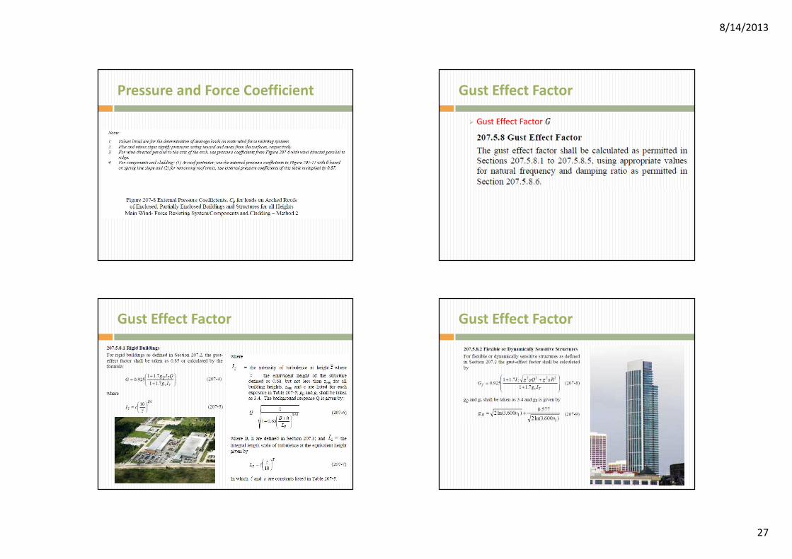
� Gust effect factors are more defined for rigid and
flexible structures (Section 207.5.8).

8/14/2013
13
Highlights of Significant Provisions in
Section 207 – Wind Loads
Highlights of Significant Provisions in
Section 207 – Wind Loads
Highlights of Significant Provisions in
Section 207 – Wind Loads
Highlights of Significant Provisions in
Section 207 – Wind Loads
� Gust effect factors
for other structures
such as poles,
masts, trussed
towers, billboard
structures, free-
standing wall and
solid signs are also
defined.
(Section 207.7)
Table 207-5.

8/14/2013
14
Highlights of Significant Provisions in
Section 207 – Wind Loads
Highlights of Significant Provisions in
Section 207 – Wind Loads
Highlights of Significant Provisions in
Section 207 – Wind Loads
Highlights of Significant Provisions in
Section 207 – Wind Loads

8/14/2013
15
Highlights of Significant Provisions in
Section 207 – Wind Loads
� Wind loads on all
structures
supporting
antennas, cables
and other
attachments and
appurtenances shall
be referred to TIA-
222-G (2005)
(Section 207.5.15.2)
Calculation Procedure
� Sixth Edition of NSCP Volume I, 2010
� Sections 207.4 through 207.6 of the NSCP 2010 prescribe
the provisions for the design procedure that may be
adopted in the calculation of wind forces on the structure
MWFRS and its components and cladding (C&C).
� Method 1 – Simplified Procedure
Calculation Procedure
� Method 1 – Simplified Procedure
� as specified in Section 207.4 the simplified
procedure may be applied to buildings
meeting certain specific requirements
which are set for MWFRS and C&C,
respectively
� generally used for evaluating design loads
for common regular shaped low-rise
buildings
Calculation Procedure

8/14/2013
16
Calculation Procedure
� Method 2 – Analytical
Procedure
Calculation Procedure
� Method 2 – Analytical Procedure
� as specified in Section 207.5 analytical
procedure is applicable to buildings and
other structures – buildings of all heights;
alternate low-rise buildings with mean
roof height less than or equal to 18 m; or
open buildings and other structures not
susceptible to across wind loading or
other special considerations due to
location
Calculation Procedure
� Method 3 – Wind
Tunnel Procedure
Calculation Procedure
� Method 3 – Wind Tunnel Procedure
� must meet certain test conditions as specified in Section 207.6 for the proper conduct of such tests
� particularly useful for obtaining detailed information about pressure distributions on complex shapes and the dynamic response of structures

8/14/2013
17
Design Wind Pressure / Force
� Rigid Buildings of All
Heights
Design Wind Pressure / Force
� Low-Rise Buildings
Design Wind Pressure / Force
� Flexible Buildings
Design Wind Pressure / Force
� Components & Cladding
elements of Parapets

8/14/2013
18
Design Wind Pressure / Force
� Open Buildings with
Monoslope, Pitched or
Trough Slope
Design Wind Pressure / Force
� Solid Free-standing Walls and Solid Signs
Design Wind Pressure / Force
� Other Structures
Velocity Pressure
� Velocity Pressure �� � 47.3�10���������

8/14/2013
19
Velocity Pressure
� �� � 47.3�10���������
Velocity Pressure
Velocity Pressure
� �� � 47.3�10���������
Velocity Pressure

8/14/2013
20
Velocity Pressure Velocity Pressure
Velocity Pressure
� �� � 47.3�10���������
Velocity Pressure

8/14/2013
21
Velocity Pressure
� �� � 47.3�10���������
Velocity Pressure
Velocity Pressure
� Wind Zone Map of
the Philippines
Velocity Pressure
� Wind Zone for the
Different Provinces
of the Philippines

8/14/2013
22
Velocity Pressure
� �� � 47.3�10���������
Exposure Category
� Exposure
Exposure Category Exposure Category

8/14/2013
23
Exposure Category
� Example Scenario of
Exposure Category B
Exposure Category
Exposure Category Exposure Category
� Example Scenario of
Exposure Category C

8/14/2013
24
Exposure Category
� Example Scenario of
Exposure Category C
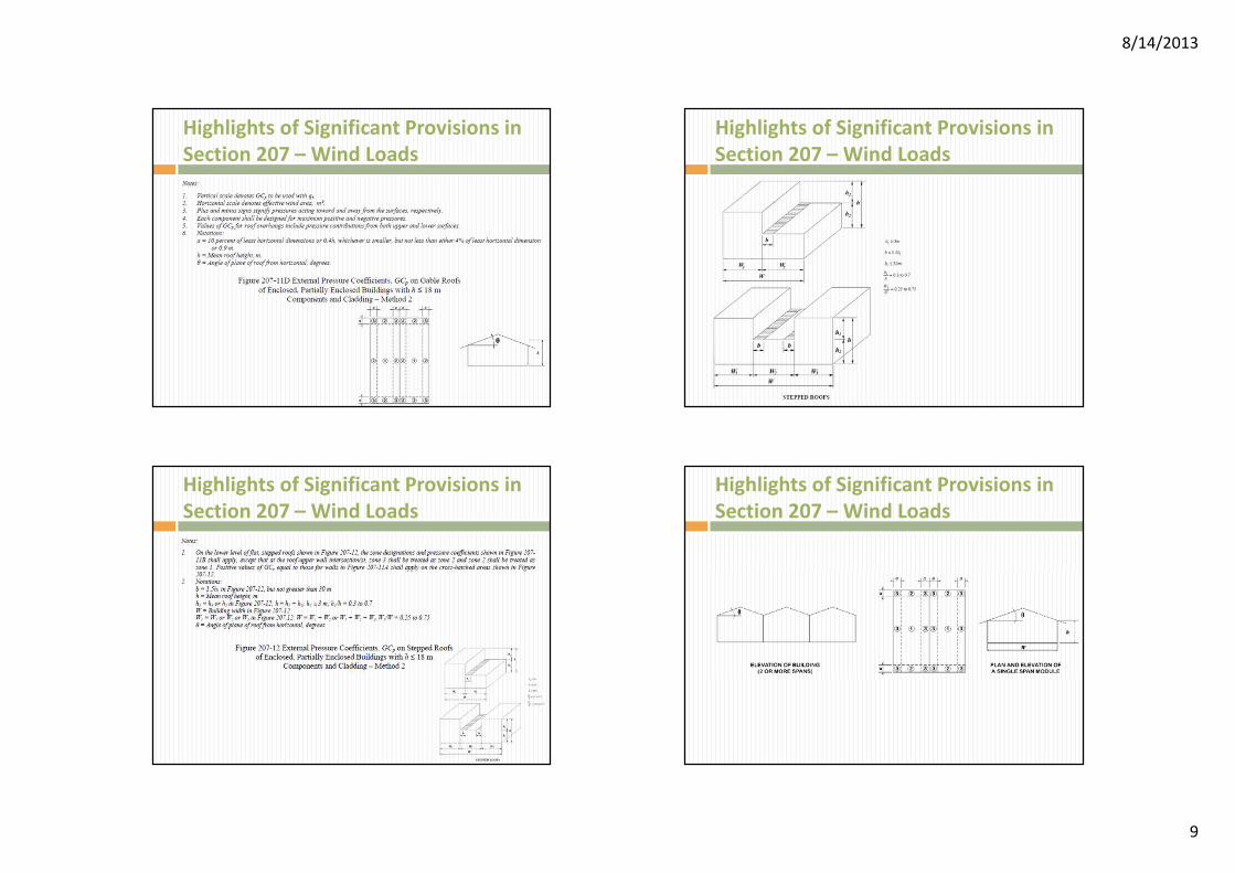
Pressure and Force Coefficient
� Internal Pressure Coefficient ����
Pressure and Force Coefficient Pressure and Force Coefficient
� External Pressure Coefficient ���

8/14/2013
25
Pressure and Force Coefficient
� Refer to Figure 207-6 of NSCP v1 2010
Pressure and Force Coefficient
Pressure and Force Coefficient Pressure and Force Coefficient

8/14/2013
26
Pressure and Force Coefficient Pressure and Force Coefficient
� Refer to Figure 207-7 of NSCP v1 2010
Pressure and Force Coefficient Pressure and Force Coefficient
� Refer to Figure 207-8 of NSCP v1 2010
8/14/2013
27
Pressure and Force Coefficient Gust Effect Factor
� Gust Effect Factor �
Gust Effect Factor Gust Effect Factor

8/14/2013
28
Gust Effect Factor Gust Effect Factor
Example Problem 1
� Given a 60-m x 75-m Gable Roof Warehouse
Building with dimensions and framing as shown
below:
Example Problem 1
� Design parameters:
� Location: The Fort Global City, Taguig City
� Topography: Homogeneous
� Terrain: Flat, open terrain
� Dimensions: 60-m x 75-m in plan
� Eave height = 6 m
� Roof slope 4:12 (18.4°)

8/14/2013
29
Example Problem 1
� Framing configuration:
� Framing: Rigid frames span the 60-m direction
� Rigid frame bay spacing = 7.5 m
� Lateral bracing in the 75-m direction is provided by a “wind truss” spanning the 60-m to side walls and cable/rod bracing in the plane of the walls
� Girts and purlins span between rigid frames (7.5 m)
� Girt spacing = 1.6 m
� Purlin spacing = 1.2 m
Example Problem 1
� Framing configuration:
� Cladding: Roof panel dimensions = 0.6 m
� Roof fastener spacing on purlins = 0.3 m on
center
� Wall panel dimensions = 0.6 m x 6 m
� Wall fastener spacing on girts = 0.3 m on
center
� Openings are uniformly distributed
Solution and Discussion to Example
Problem 1
� Exposure
and Building
Classification
The building is located on flat and
open terrain. It may not fit
Exposure Category B or D;
therefore, Exposure Category C
is considered.
The building function is commercial
- industrial. It is not an essential
facility or likely to be occupied
by 300 persons at one time.
Occupancy Category IV is
appropriate; therefore, �� = 1.0
� Reference /
Notes
Sections
207.5.6.2 and
207.5.6.3
Section
207.5.6
Table 207-3
Solution and Discussion to Example
Problem 1
� Basic Wind
Speed
� Calculation
Procedure
The building location is in Metro
Manila (NCR) which in Zone II
of the Philippine Wind Zone
Map. Therefore, the basic
wind speed is � = 200 kph.
Method 2, Analytical Procedure,
will be used in this example. In
addition, provisions of
buildings of all heights, given
in Section 207.5.12.2.1 for
MWFRS will be used.
� Reference /
Notes
Table 207-1 or
Figure 207-24
Section 207.5

8/14/2013
30
Solution and Discussion to Example
Problem 1
� Wind
Directionality
� Velocity
Pressure
Wind directionality factor = 0.85 for MWFRS and C&C.
The velocity pressures are computed using the following equation:�� � 47.3�10������
���
where
� = ?
�� = 1.0 (no topographic effect)
= 0.85
�� = 1.0
� = 200 kph
� Reference /
Notes
Section
207.5.4.4 or
Table 207-2
Section
207.5.10
Equation 207-
15
Table 207-4
Section
207.5.7
Solution and Discussion to Example
Problem 1
� Velocity
Pressure Substituting the values into
Equation 207-15 yields:�� � 47.3�10����1��0.85� 200
��1�
�� � 1608.2� N/m2
*�� � 1608.2� N/m2
� Reference /
Notes
Section
207.5.4.4 or
Table 207-2
� is based on
Note 2 of
Table 207-4.
Values for �are the same
for Cases 1
and 2 for
Exposure C.
Mean roof
height � = 11
m.
Height Elev. (m) � �� (N/m2)
4.50 0.85 1367
Eave 6.00 0.90 1447
9.00 0.98 1576
� 11.00 1.02 1640*
12.00 1.04 1673
15.00 1.09 1753
Ridge 16.00 1.10 1769
Solution and Discussion to Example
Problem 1
� Design Wind
Pressure
Design wind pressures for MWFRS of this building can be obtained using Section 207.5.12.2.1 for buildings of all heights or Section 207.5.12.2.2 for low-rise buildings. In this example, pressures are determined using buildings of all heights criteria:
� � ���� & ��������
where
� � �� for windward wall at height � above ground
� � �� for leeward wall, side walls, and roof at height �
�� � �� for enclosed buildings
� = gust effect factor
�� = external pressure coefficient
������ = internal pressure coefficient
� Reference /
Notes
Section
207.5.4.4 or
Table 207-2
Section
207.5.12.2.1
Equation 207-
17
Figure 207-6
Figure 207-5
Solution and Discussion to Example
Problem 1

8/14/2013
31
Solution and Discussion to Example
Problem 1
Solution and Discussion to Example
Problem 1
� Design Wind
PressureFor this example, when the wind is
normal to the ridge, the windward roof experiences both positive and negative external pressures. Combining these external pressures with positive and negative external pressures will result in four loading cases when wind is normal to the ridge.
When wind is parallel to the ridge, positive and negative internal pressures result in two loading cases. The external pressure coefficients �� for θ = 0° apply in this case.
� Reference /
Notes
Figure 207-6
Solution and Discussion to Example
Problem 1
� External
Pressure
Coefficient
�� on Wall
The pressure coefficients for the windward wall and for the side walls are 0.8 and -0.7, respectively, for all '/(ratios.
The leeward wall pressure coefficient is a function of '/( ratio. For wind normal to the ridge, '/( = 60/75 = 0.8; therefore, the leeward wall pressure coefficient is -0.5.
� Reference /
Notes
Figure 207-6
Solution and Discussion to Example
Problem 1
� External
Pressure
Coefficient
�� on Wall
� Reference /
Notes

8/14/2013
32
Solution and Discussion to Example
Problem 1
� External
Pressure
Coefficient
�� on Wall
For wind parallel to the ridge, '/( =
75/60 = 1.25; the value of ��,
obtained by linear interpolation, = -
0.45.
In summary, the wall pressure coefficients
are:
� Reference /
Notes
Figure 207-6
Surface Wind direction '/( ��
Windward wall All All 0.80
Leeward wall Normal to
ridge0.8 -0.50
Parallel to
ridge1.25 -0.45
Side wall All All -0.70
Solution and Discussion to Example
Problem 1
� External
Pressure
Coefficient
�� on Roof
The roof pressure coefficients for
the MWFRS are determined
and shown below:
*Values obtained by linear interpolation. For
wind normal to ridge, �/' = 11/60 = 0.186.
� Reference /
Notes
Figure 207-6
Surface 15° 18.4° 20°
Windward
roof-0.5 -0.36* -0.3
0.0 0.14* 0.2
Leeward
roof-0.5 -0.57* -0.6
Solution and Discussion to Example
Problem 1
� External
Pressure
Coefficient
�� on Roof
� Reference /
Notes
Figure 207-6
Solution and Discussion to Example
Problem 1
� Internal
Pressure
Coefficient
����
Values for ���� for buildings are
addressed in:
The openings are evenly distributed in the walls (enclosed building). The reduction factor of Section 207.5.11.1.1 is not applicable for enclosed buildings;
therefore, ���� = ±0.18
� Reference /
Notes
Section
207.5.11.1
Figure 207-5

8/14/2013
33
Solution and Discussion to Example
Problem 1
� Gust Effect
Factor �For rigid structures (where the ratio of
� to the least width of building = 16/60 = 0.18 < 4), hence, rigid building, � can be calculated using Equation 207-4:
� � 0.9251 * 1.7+,��̅.
1 * 1.7+/��̅where
+, = +/ = 3.4
�̅ � 0.6� = 0.6(11) = 6.6 m or �̅ � �0�1 = 4.5 m
2 = 0.2
ℓ = 150 m
ε5 = 1/5
� Reference /
Notes
Section
207.5.8.1
Table 207-5
Solution and Discussion to Example
Problem 1
� Gust Effect
Factor �
� Reference /
Notes
Table 207-5
Solution and Discussion to Example
Problem 1
� Gust Effect
Factor �Then, compute the other notations
��̅ � 267
�̅
6/�
� 0.267
�.�
6/�
��̅ � 0.214
. �1
1 * 0.63( * �'�̅
7.�8
in which
'�̅ � ℓ�̅
10
9̅
� 1506.6
106/;
'�̅ � 138.04
� Reference /
Notes
Section
207.5.8.1
Equation 207-
5
Equation 207-
6, use ( = 60
m (the smaller
value gives
larger value of
�)
Equation 205-
7
Solution and Discussion to Example
Problem 1
� Gust Effect
Factor � Then,
. �6
6<7.�8=>?@@
@AB.>C
>.=A
. � 0.84
Substituting the computed
values to evaluate �:
� � 0.9251 * 1.7�3.4��0.214��0.84�
1 * 1.7�3.4��0.214�
� � 0.883
� Reference /
Notes
Equation 207-
6
Equation 207-
4

8/14/2013
34
Solution and Discussion to Example
Problem 1
� Net Wind
Pressures on
MWFRS
Wind pressure on the MWFRS is
determined as
� � ���� & ��������� � ��0.883��� & �1640��D0.18�
On the windward wall from 0 –
4.5 m, wind normal to ridge:
� � 1367�0.883��0.8� & �1640��D0.18�
� � 670 N/m2 with (+) internal pressure
� � 1261 N/m2 with (-) internal pressure
� Reference /
Notes
Equation 207-
17
Solution and Discussion to Example
Problem 1
� Net Wind
Pressures on
MWFRS
In summary, the net pressures
for the MWFRS (wind normal
to ridge) are shown in table:
� Reference /
Notes
Surface � (m) � (N/m2) � ��Net pressure (N/m2) with
(+����) (-����)
Windward
wall4.50 1367 0.883 0.80 670 1261
6.00 1447 0.883 0.80 727 1317
Leeward
wallAll 1640 0.883 -0.50 -1019 -429
Side walls All 1640 0.883 -0.70 -1309 -719
Windward
roof* - 1640 0.883-0.36 -816 -226
0.14 -92 498
Leeward
roof- 1640 0.883 -0.57 -1120 -530
Solution and Discussion to Example
Problem 1
� Net Wind
Pressures on
MWFRS
From previous calculation, note
that �� = 1640 N/m2; ���� =
±0.18; therefore, the quantity
��(����) = ±295 N/m2
*Two loadings on windward roof
and two internal pressures
yield a total of four loading
cases.
� Reference /
Notes
Refer to
Figures 1-1
through 1-2 in
next slides
Solution and Discussion to Example
Problem 1
� Net Wind
Pressures on
MWFRS
Figure 1-1 – Net Design Wind Pressures for MWFRS
when Wind is Normal to Ridge with Negative
Windward External Roof Pressure Coefficient
� Reference /
Notes
Surface � (m) � (N/m2) � ��Net pressure (N/m2) with
(+����) (-����)
Windward
wall4.50 1367 0.883 0.8 670 1261
6.00 1447 0.883 0.8 727 1317
Leeward
wallAll 1640 0.883 -0.5 -1019 -429
Side walls All 1640 0.883 -0.7 -1309 -719
Windward
roof*- 1640 0.883
-0.36 -816 -226
0.14 -92 498
Leeward
roof- 1640 0.883 -0.57 -1120 -530

8/14/2013
35
Solution and Discussion to Example
Problem 1
� Net Wind
Pressures on
MWFRS
Figure 1-2 – Net Design Wind Pressures for
MWFRS when Wind is Normal to Ridge with
Negative Windward External Roof Pressure
Coefficient
� Reference /
Notes
Surface � (m) � (N/m2) � ��Net pressure (N/m2) with
(+����) (-����)
Windward
wall
4.50 1367 0.883 0.8 670 1261
6.00 1447 0.883 0.8 727 1317
Leeward
wallAll 1640 0.883 -0.5 -1019 -429
Side walls All 1640 0.883 -0.7 -1309 -719
Windward
roof*- 1640 0.883
-0.36 -816 -226
0.14 -92 498
Leeward
roof- 1640 0.883 -0.57 -1120 -530
Solution and Discussion to Example
Problem 1
� Net Wind
Pressures on
MWFRS
Figure 1-3 – Net Design Wind Pressures for
MWFRS when Wind is Normal to Ridge with
Positive Windward External Roof Pressure
Coefficient
� Reference /
Notes
Surface � (m) � (N/m2) � ��Net pressure (N/m2) with
(+����) (-����)
Windward
wall
4.50 1367 0.883 0.8 670 1261
6.00 1447 0.883 0.8 727 1317
Leeward
wallAll 1640 0.883 -0.5 -1019 -429
Side walls All 1640 0.883 -0.7 -1309 -719
Windward
roof*- 1640 0.883
-0.36 -816 -226
0.14 -92 498
Leeward
roof- 1640 0.883 -0.57 -1120 -530
Solution and Discussion to Example
Problem 1
� Net Wind
Pressures on
MWFRS
Figure 1-4 – Net Design Wind Pressures for
MWFRS when Wind is Normal to Ridge with
PositiveWindward External Roof Pressure
Coefficient
� Reference /
Notes
Surface � (m) � (N/m2) � ��Net pressure (N/m2) with
(+����) (-����)
Windward
wall
4.50 1367 0.883 0.8 670 1261
6.00 1447 0.883 0.8 727 1317
Leeward
wallAll 1640 0.883 -0.5 -1019 -429
Side walls All 1640 0.883 -0.7 -1309 -719
Windward
roof*- 1640 0.883
-0.36 -816 -226
0.14 -92 498
Leeward
roof- 1640 0.883 -0.57 -1120 -530
Solution and Discussion to Example
Problem 1
� External
Pressure
Coefficient
�� on Roof
(Wind
Parallel to
Ridge)
� Reference /
Notes
Figure 207-6For wind parallel to ridge, �/' = 11/75 = 0.147 and θ < 10°. The values of
�� for wind parallel to ridge are:
*The values of smaller uplift pressures on the roof can become critical with roof live load; load combinations are given in Sections 203.3 and 203.4.
Surface �/'Distance from
windward edge��
Roof ≤ 0.5 0 to � -0.9, -0.18*
� to 2� -0.5, -0.18*
> 2� -0.3, -0.18*

8/14/2013
36
Solution and Discussion to Example
Problem 1
� External
Pressure
Coefficient
�� on Roof
(Wind
Parallel to
Ridge)
� Reference /
Notes
Figure 207-6
Solution and Discussion to Example
Problem 1
� External
Pressure
Coefficient
�� on Roof
(Wind
Parallel to
Ridge)
� Reference /
Notes
Refer to
Figures 1-5
through 1-6 in
next slide
The net pressures for the MWFRS (wind parallel to ridge) are:
�� = 1640 N/m2; ���� = ±0.18;
�������� = ±295 N/m2
*Distance from windward edge.
Surface � (m) � (N/m2) � ��Net pressure (N/m2) with
(+����) (-����)
Windward wall 0 - 4.50 1367 0.883 0.80 670 1260
6.00 1447 0.883 0.80 727 1317
9.00 1576 0.883 0.80 818 1408
12.00 1673 0.883 0.80 886 1476
15.00 1753 0.883 0.80 943 1533
16.00 1769 0.883 0.80 954 1544
Leeward wall All 1640 0.883 -0.45 -947 -357
Side walls All 1640 0.883 -0.70 -1309 -719
Roof* 0 to h* 1640 0.883 -0.90 -1598 -1008
h to 2h* 1640 0.883 -0.50 -1019 -429
> 2h* 1640 0.883 -0.30 -729 -139
Solution and Discussion to Example
Problem 1
� External
Pressure
Coefficient
�� on Roof
(Wind
Parallel to
Ridge)
Figure 1-5 –Net Design Wind Pressures for MWFRS when Wind
is Parallel to Ridge with Positive Internal Pressure
� Reference /
Notes
Surface � (m) � (N/m2) � ��Net pressure (N/m2) with
(+����) (-����)
Windward wall 0 - 4.50 1367 0.883 0.80 670 1260
6.00 1447 0.883 0.80 727 1317
9.00 1576 0.883 0.80 818 1408
12.00 1673 0.883 0.80 886 1476
15.00 1753 0.883 0.80 943 1533
16.00 1769 0.883 0.80 954 1544
Leeward wall All 1640 0.883 -0.45 -947 -357
Side walls All 1640 0.883 -0.70 -1309 -719
Roof* 0 to h* 1640 0.883 -0.90 -1598 -1008
h to 2h* 1640 0.883 -0.50 -1019 -429
> 2h* 1640 0.883 -0.30 -729 -139
Solution and Discussion to Example
Problem 1
� External
Pressure
Coefficient
�� on Roof
(Wind
Parallel to
Ridge)
� Reference /
Notes
Surface � (m) � (N/m2) � ��Net pressure (N/m2) with
(+����) (-����)
Windward wall 0 - 4.50 1367 0.883 0.80 670 1260
6.00 1447 0.883 0.80 727 1317
9.00 1576 0.883 0.80 818 1408
12.00 1673 0.883 0.80 886 1476
15.00 1753 0.883 0.80 943 1533
16.00 1769 0.883 0.80 954 1544
Leeward wall All 1640 0.883 -0.45 -947 -357
Side walls All 1640 0.883 -0.70 -1309 -719
Roof* 0 to h* 1640 0.883 -0.90 -1598 -1008
h to 2h* 1640 0.883 -0.50 -1019 -429
> 2h* 1640 0.883 -0.30 -729 -139

8/14/2013
37
Solution and Discussion to Example
Problem 1
� External
Pressure
Coefficient
�� on Roof
(Wind
Parallel to
Ridge)
Figure 1-6 –Net Design Wind Pressures for MWFRS when Wind
is Parallel to Ridge with Negative Internal Pressure
� Reference /
Notes
Surface � (m) � (N/m2) � ��Net pressure (N/m2) with
(+����) (-����)
Windward wall 0 - 4.50 1367 0.883 0.80 670 1260
6.00 1447 0.883 0.80 727 1317
9.00 1576 0.883 0.80 818 1408
12.00 1673 0.883 0.80 886 1476
15.00 1753 0.883 0.80 943 1533
16.00 1769 0.883 0.80 954 1544
Leeward wall All 1640 0.883 -0.45 -947 -357
Side walls All 1640 0.883 -0.70 -1309 -719
Roof* 0 to h* 1640 0.883 -0.90 -1598 -1008
h to 2h* 1640 0.883 -0.50 -1019 -429
> 2h* 1640 0.883 -0.30 -729 -139
Solution and Discussion to Example
Problem 1
� Design Wind
Load Cases
� Reference /
Notes
Section 207.5.12.3 requires that
any building whose wind
loads have been determined
under the provisions of
Sections 207.5.12.2.1 and
207.5.12.2.3 shall be
designed for wind load cases
as defined in Figure 207-9.
Solution and Discussion to Example
Problem 1
� Design Wind
Load Cases
� Reference /
Notes
Section
207.5.12.3 has
exception that
if a building is
designed with
flexible
diaphragm,
only load cases
1 and 3 need
to be
considered.
Figure 207-9
p.2-47

8/14/2013
38
Solution and Discussion to Example
Problem 1
� Design Wind
Pressures on
Components
& Cladding
(C&C)
� Reference /
Notes
The following equation is used to obtain
the design pressures for components
and cladding (C&C):
� � �� ��� & ����
� � 1640 ��� & D0.18
where ��� values are obtained
from Figure 207-11A