ASE 8 - Engine Performance - Community College of...
20
ASE 8 - Engine Performance Module 12 Powertrain Control Outputs
Transcript of ASE 8 - Engine Performance - Community College of...
ASE 8 - Engine Performance
Module 12Powertrain Control Outputs

AcknowledgementsGeneral Motors, the IAGMASEP Association Board of Directors, and RaytheonProfessional Services, GM's training partner for GM's Service Technical College wish tothank all of the people who contributed to the GM ASEP/BSEP curriculum developmentproject 2002-3. This project would not have been possible without the tireless efforts ofmany people. We acknowledge:
• The IAGMASEP Association members for agreeing to tackle this large project tocreate the curriculum for the GM ASEP/BSEP schools.
• The IAGMASEP Curriculum team for leading the members to a single vision andimplementation.
• Direct contributors within Raytheon Professional Services for their support oftranslating a good idea into reality. Specifically, we thank:
– Chris Mason and Vince Williams, for their leadership, guidance, and support.– Media and Graphics department under Mary McClain and in particular, Cheryl
Squicciarini, Diana Pajewski, Lesley McCowey, Jeremy Pawelek, & NancyDeSantis.
– For their help on the Engine Performance curriculum volume, Subject MatterExperts, John Beggs and Stephen Scrivner, for their wealth of knowledge.
Finally, we wish to recognize the individual instructors and staffs of the GM ASEP/BSEPColleges for their contribution for reformatting existing General Motors training material,adding critical technical content and the sharing of their expertise in the GM product.Separate committees worked on each of the eight curriculum areas. For the work on thisvolume, we thank the members of the Engine Performance committee:
– Jamie Decato, New Hampshire Community Technical College– Lorenza Dickerson, J. Sargeant Reynolds Community College– Marvin Johnson, Brookhaven College– Jeff Rehkopf, Florida Community College at Jacksonville– David Rodriguez, College of Southern Idaho– Paul Tucker, Brookdale Community College– Kelly Smith, University of Alaska– Ray Winiecki, Oklahoma State University - Okmulgee

ContentsModule 12 – Powertrain Control OuptutsAcknowledgements .......................................................................................... 2Introduction ...................................................................................................... 4Objectives ........................................................................................................ 4
Devices ........................................................................................................................... 5Control Circuits ............................................................................................................... 5Ignition Control .............................................................................................................. 10Fuel Control ...................................................................................................................11Engine Cooling Fans..................................................................................................... 17Transmission and Transaxle Control ............................................................................ 18

© 2002 General Motors CorporationAll Rights Reserved
ASE 8 - EnginePerformance
Module 12 -Powertrain ControlOutputs
12-4
Student WorkbookIntroductionNATEF Area VIII. Engine PerformanceB. Computerized Engine Controls Diagnosis and Repair
6. Inspect and test computerized engine control system sensors,powertrain control module (PCM), actuators, and circuits using agraphing multimeter (GMM)/digital storage oscilloscope (DSO);perform necessary action. P-1
7. Obtain and interpret scan tool data. P-18. Access and use service information to perform step-by-step
diagnosis. P-19. Diagnose driveability and emissions problems resulting from
malfunctions of interrelated systems (cruise control, securityalarms, suspension controls, traction controls, A/C, automatictransmissions, non-OEM-installed accessories, or similar systems);determine necessary action. P-3
STC Standards
ALL Competencies for Electrical Stage 3 18043.03 WB. Automotive Computers
7 Identify types of computer output signals8 Identify types of actuators used
A-8 Competencies for GM Powertrain Performance 16044.10 W/D/HF. PCM Engine Control Management
3 Describe PCM outputs which control engine performance
ObjectivesUpon successful completion of engine performance Module 12, the ASEPstudent will be able to:• Define output circuit terms• Identify output circuit components• Explain output circuit operation• Perform output circuit test

© 2002 General Motors CorporationAll Rights Reserved
ASE 8 - EnginePerformance
Module 12 -Powertrain ControlOutputs
12-5
Student WorkbookOutput DevicesThere are two types of output devices. They are relays and solenoids.Relays are used to control high current draw components with thePCM controlling the low current armature circuit. Solenoids arecontrolled directly by the PCM.
Control CircuitsDiscrete CircuitMost electrically operated devices are controlled by the PCM simply byturning them ON and OFF, often providing and removing ground.
Pulse Width Modulation CircuitTurning a circuit ON and OFF very rapidly or pulsing it can achieve avarying range. Controlling the voltage in this manner is referred to as"Pulse Width Modulation," or PWM. Pulse means turning ON and OFF.Width means the amount of time the voltage is ON compared with theamount it is OFF. Finally, modulation refers to the fact that the circuit isbeing controlled or modulated over an operating range.
Figure 12-1, Pulse Width Modulation Circuit

© 2002 General Motors CorporationAll Rights Reserved
ASE 8 - EnginePerformance
Module 12 -Powertrain ControlOutputs
12-6
Student WorkbookDriver CircuitsThere are several types of quad drivers. Carbureted vehicles built in theearly 1980s were equipped with a fusible quad driver, or QDR, in thePCM. The fusible driver was unprotected and failed when exposed to ahigh amperage load, or when subjected to an amperage load at or near itslimit for a prolonged period of time.A Quad Driver 2, or QDR2, is protected. All new and some reconditionedPCMs are updated with current limiting quad drivers. When this type ofquad driver is overloaded, it limits circuit current to protect itself. If thecurrent to a solenoid or relay is being limited because of a shorted circuitor coil, the amperage may be too low to allow the component to function.If sufficient heat builds up, the quad driver may cease functioning due tothermal shut down. When this happens, all the components controlled bythe QDR will stop functioning.Quad driver modules, or QDMs, work like QDR2s, incorporating protectionagainst circuit faults. They may also contain a fault line to provide afeedback signal to the PCM. The signal allows the PCM to help theservice technician to locate an output fault by setting diagnostic troublecodes through readouts on the data stream.
Figure 12-2, Quad Driver Circuits
Another type of driver is the Output driver Module, or ODM. The ODM isthe latest in output driver technology and can control seven outputs ofvarying currents. ODMs offer circuit protection and data buscommunications with the central processor to specify which output isat fault.

© 2002 General Motors CorporationAll Rights Reserved
ASE 8 - EnginePerformance
Module 12 -Powertrain ControlOutputs
12-7
Student WorkbookOutput CommandsThere are a number of commands given by the PCM as outputs.
Malfunction Indicator Lamp (MIL)The Malfunction Indicator Lamp, or MIL, comes on when the ignition key isturned to the on position, with the engine not running. This position servesas a bulb check. In some newer systems the light comes on for threeseconds and then goes out.With the engine running, the MIL is normally off. If a trouble code storesor the PCM goes into backup mode, the MIL comes on. If the conditionchanges and the trouble no longer exist the light may go off but thediagnostic trouble code, or DTC, remains stored in the PCM memory. InOBD II compliant vehicles, the MIL stays on for three passing trips afterthe fault is no longer present.
Up-shift LightOn manual transmission vehicles, the upshift light on the instrument panelindicates when it is appropriate to shift to the next higher gear to obtainoptimum fuel economy while maintaining comparable vehicleperformance. The PCM uses information from the ECT, TP, VSS, MAP orMAF sensor, and Engine RPM in determining when to illuminate theupshift light.The PCM uses the indicated RPM and vehicle speed to calculate whatgear the transmission is in. Airflow, RPM, and throttle position indicateengine load.
Temp Warning LightSome vehicles have a "Temp" Warning Light in the instrument cluster,controlled by the PCM. The "Temp" warning light is activated by the PCM,which provides a ground path. On some models, for example, the light isilluminated when coolant temperature exceeds two-hundred fifty threedegrees Fahrenheit, or one hundred thirteen degrees Celsius, and noengine coolant temperature DTCs have been set.

© 2002 General Motors CorporationAll Rights Reserved
ASE 8 - EnginePerformance
Module 12 -Powertrain ControlOutputs
12-8
Student WorkbookExhaust Gas Recirculation Valve (EGR)The Exhaust Gas Recirculation, or EGR, system is used to lower Oxidesof Nitrogen emission levels caused by high combustion temperatures. Itdoes this by decreasing combustion temperatures.The main element of the system is the EGR valve. The EGR valve feedssmall amounts of exhaust gas back into the combustion chamber. Withthe air fuel mixture displaced, combustion temperatures are reduced. EGRis usually activated during warm engine operation and above idle speeds.In order to calculate EGR flow, the PCM looks at readings from ECT, TP,MAP or MAF, Ignition reference, and vehicle speed.
Linear EGR ValveMany GM applicationscurrently use a linear EGRvalve as part of emissionscontrol. EGR is used to lowercombustion temperatures tohelp limit Nitrides of Oxygen,or NOX, emissions.The PCM monitors theposition of the EGR valvethrough a feedback signal.The PCM supplies a 5vreference and a ground to theEGR pintle position sensor.A voltage signal representingthe EGR valve pintle positionis sent to the PCM from theEGR valve. A high side driverusing pulse-width modulationpositions the EGR solenoid.Unlike other system outputs,the PCM supplies voltage andground to the EGR valve.
The feedback signal can be monitored on a scan tool and is the actualposition of the EGR pintle. The Actual EGR Position should always benear the commanded or Desired EGR Position.The linear EGR valve is designed to accurately supply EGR to an engineindependent of intake manifold vacuum. The valve controls EGR flow fromthe exhaust to the intake manifold through an orifice. The PCM controlsthe pintle position by varying the magnetic field of the coil through pulse-width modulation. During operation, the PCM adjusts pintle position bymonitoring the pintle position feedback signal. The linear system providesimprovements in flow accuracy and diagnostic capabilities.
Figure 12-3, Linear EGR Valve

© 2002 General Motors CorporationAll Rights Reserved
ASE 8 - EnginePerformance
Module 12 -Powertrain ControlOutputs
12-9
Student WorkbookIdle Air Control (IAC)The Idle Air Control, or IAC, valve is located in the throttle body of bothTBI and MFI systems. It consists of a movable pintle, driven by a smallelectric motor called a stepper motor. The PCM uses the IAC valve tocontrol idle RPM. It does this by changing the pintle position in the idle airpassage of the throttle body. This varies the airflow around the throttleplate when the throttle is closed.The stepper motor is capable of moving in exact, measured amountscalled steps. Currents are reversed in the stators. Reversing the currentwill change the stator polarity, causing the rotor to rotate. Because the IACvalve is controlled by the PCM, it can make continuous precise changes inairflow to maintain proper idle speed under varying conditions.During closed throttle, the PCM constantly compares actual idle RPM withthe programmed desired idle RPM, and adjusts the IAC valve accordinglyto achieve the desired idle. In some engines, the PCM also adjustsignition timing to control idle speed even more precisely.To determine the desired position of the IAC pintle at idle or duringdeceleration, indicated by closed throttle position or zero percent throttleangle, the PCM refers to the Battery voltage, ECT, TP sensor, EngineRPM, vehicle speed, and engine load, which includes MAP or MAFsensor, AC compressor, PSP switch, and PNP switch.The pintle is moved OUT, or away, from the seat to increase airflow andRPM, and IN, or toward, the seat to decrease airflow and RPM.During each ignition key cycle, the PCM commands the IAC valve to seatitself and then to move away from the seat a calibrated number of steps.This establishes a correct reference for operation when the engine isrestarted. It also provides the exact amount of air for start-up, because thethrottle plate remains closed during engine cranking.
Figure 12-4, Idle Air Control System

© 2002 General Motors CorporationAll Rights Reserved
ASE 8 - EnginePerformance
Module 12 -Powertrain ControlOutputs
12-10
Student WorkbookValve DesignsThree styles of IAC valve pintleshave been used on GM fuel injectionsystems. One type has a single-taper, the second has a dual-taper,and the third has a blunt tip. Alwaysreplace an IAC valve with onehaving the same pintle shape anddiameter.If the IAC valve has to be replaced,be sure to observe all precautionsand follow procedures exactly asprovided in the service manual.
Figure 12-4, IAC Valves
Ignition ControlEach ignition control module has a power feed circuit, a chassis groundcircuit, ignition control circuits, and a reference low circuit. The PCMcauses spark to occur by pulsing the IC circuit, which signals the moduleto trigger the coil and fire a spark plug. The PCM and ignition modules arecircuit protected against shorts to power and ground on the IC circuits.
Figure 12-5, Ignition Controls

© 2002 General Motors CorporationAll Rights Reserved
ASE 8 - EnginePerformance
Module 12 -Powertrain ControlOutputs
12-11
Student WorkbookFuel ControlFuel Pump ControlBecause the fuel pump draws high current, it is not directly controlled bythe PCM. Instead, the PCM controls a fuel pump relay that providessystem voltage to the fuel pump.When the ignition is turned ON, before the starter is engaged, the PCMenergizes the fuel pump relay by providing system voltage. If the PCMdoes not receive ignition reference pulses within 2 seconds, it will shut offthe fuel pump relay. The PCM powers the relay circuit as long as itreceives ignition reference pulses.
On some models, the oil pressure switch provides a backup circuit to thefuel pump relay. If the fuel pump relay fails to supply power to the fuelpump, it will receive power from this circuit. This may result in extendedcrank times.This circuit is unique in that the PCM is supplying power instead ofground. This is done for safety reasons. If the fuel pump relay wasconfigured like the other outputs, a short to ground would cause the pumpto continue to operate even when the engine was not running.An inoperative fuel pump will cause a no-start condition. A defective relaycan result in long engine cranking times or a "no-start" condition if thevehicle is not equipped with an oil pressure switch backup circuit.
Figure 12-6, Fuel Pump Control

© 2002 General Motors CorporationAll Rights Reserved
ASE 8 - EnginePerformance
Module 12 -Powertrain ControlOutputs
12-12
Student WorkbookFuel InjectorsFuel is delivered by the fuel injector, which is controlled by the PCM. Thefuel injector is provided a continuous supply of pressurized fuel by theelectric fuel pump. The PCM controls fuel flow by pulse width modulationof the injector, or ON time. The ON time of the injector is determined byEngine temperature, intake air temperature, engine RPM, throttle position,manifold pressure or mass airflow, the oxygen sensor, engine load, andsystem voltage.When fuel requirements increase, the injector on time increases,producing a richer air fuel mixture. When fuel requirements decrease, theinjector on time decreases, producing a leaner mixture.
Figure 12-7, Fuel Injectors
A fuel injector is an electromagnetic device. The precision mechanicalcomponents are controlled by means of the solenoid in the injector, andthe solenoid is energized through an injector driver in the PCM. Theinjector is triggered based on ignition reference pulses.Although engine RPM determines when an injector opens, the PCMdetermines how long to leave the injector open. How long the injector isopen determines how much fuel is delivered; in other words, how richor lean the air fuel mixture is. The duration of this on time is called thepulse width.

© 2002 General Motors CorporationAll Rights Reserved
ASE 8 - EnginePerformance
Module 12 -Powertrain ControlOutputs
12-13
Student WorkbookThe PCM driver circuit controls theon time of the solenoid by providinga ground. When the injector driveropens the circuit to the solenoidagain and turns it off, return springtension closes the ball or pintle onits seat and shuts off fuel flow.There are two principal types ofinjector drivers: saturated switchand peak-and-hold.A saturated switch drive circuit isused with injectors having relativelyhigh resistance, generally twelve tosixteen ohms. The circuit resistancelimits maximum current. There is noseparate current limiting function.With this type of driver, the injectorcoil takes longer to build andcollapse its magnetic field. Whenthe injector driver opens the circuitto the injector's solenoid, returnspring tension closes the ball orpintle on its seat and shuts off fuelflow.
A peak-and-hold injector drive circuit is used in conjunction with relativelylow resistance injectors, one to two ohms. It incorporates a currentlimiting device to prevent overheating of the injector coil. The currentlimiting circuit monitors the current flow through the injectors. Whencurrent reaches the maximum level, it is reduced to avoid damage to theinjector solenoid. Current is then maintained at a level sufficient to holdthe valve off the seat for the required injection period. With this type ofdriver, the injector opens and closes more quickly, giving more precise fuelcontrol over a very broad operating range. Peak-and-hold injector driversare used in both TBI, and bottom feed, and MFI, or top feed, injectors.
Figure 12-8, Injector Voltage Patterns

© 2002 General Motors CorporationAll Rights Reserved
ASE 8 - EnginePerformance
Module 12 -Powertrain ControlOutputs
12-14
Student WorkbookEnhanced Evaporative SystemThe Enhanced Evaporative, or EVAP, Emission system used on OBD IIvehicles consists of an Evaporative system canister, a Fuel tank pressuresensor, Canister purge valve, Canister vent valve, Fuel level sensor, Fueltank, Fuel cap, and Service port.EVAP canister purge occurs when the engine runs for a specified time,coolant temperature is above a specified value, and the vehicle speedabove a specified MPH or throttle is off-idle.
Figure 12-10, Enhanced EVAP System
When energized, the evaporative canister purge valve allows fuel vapor toflow from the canister to the engine. The normally closed valve is pulsewidth modulated by the controlmodule to precisely control vaporflow. The valve is opened during theenhanced evaporative diagnostictests to create a vacuum in the fueltank and then closed to seal thesystem.The evaporative canister vent valvereplaces the fresh air vent used onpast canisters. The normally openvent valve now not only allows freshoutside air to the canister duringpurge modes, but also allows thediagnostic to pull a vacuum on thefuel tank by closing the vent valve.
Figure 12-11, EVAP Valves

© 2002 General Motors CorporationAll Rights Reserved
ASE 8 - EnginePerformance
Module 12 -Powertrain ControlOutputs
12-15
Student WorkbookSecondary Air Injection SystemThe Secondary Air Injection system consists of an air pump, control valvesfor switching and or diverting, check valves, and necessary plumbing. Inmany applications, a belt drives the air pump on the front of the engine. Inthe other applications the air pump is electric, which reduces the load onthe engine.On cold start-up, oxygen is pumped into the exhaust manifold to continuecombustion after the exhaust gases leave the combustion chamber.During cold operation, hydrocarbon, or HC, and Carbon Monoxide, or CO,output can be high. Extending combustion reduces HC and CO emissionsin the exhaust. On some systems, air is switched to the catalyticconverter after warm-up. The catalytic converter is used to control HC andCO emissions through oxidation. The AIR system provides additionaloxygen to help lower HC and CO levels in the exhaust gases even further.
The PCM turns the AIR pump OFF after a set time or under certainengine operating conditions. At the same time, the integral stop valve isde-energized, so no air is directed to the exhaust ports. The AIR systemwill shut OFF when the system goes into closed loop, when the AIR pumphas been "ON" for a set time, when the air fuel mixture is too rich, engineparameters are out of range, when the catalytic converter is overtemperature, the PCM recognizes a problem and sets a diagnostictrouble code.
Figure 12-11, Secondary Air Injection System
© 2002 General Motors CorporationAll Rights Reserved
ASE 8 - EnginePerformance
Module 12 -Powertrain ControlOutputs
12-16
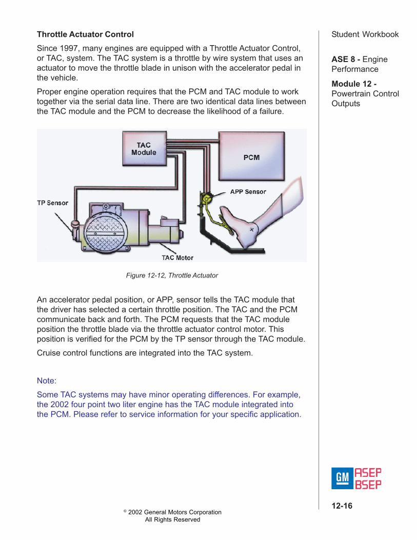
Student WorkbookThrottle Actuator ControlSince 1997, many engines are equipped with a Throttle Actuator Control,or TAC, system. The TAC system is a throttle by wire system that uses anactuator to move the throttle blade in unison with the accelerator pedal inthe vehicle.Proper engine operation requires that the PCM and TAC module to worktogether via the serial data line. There are two identical data lines betweenthe TAC module and the PCM to decrease the likelihood of a failure.
An accelerator pedal position, or APP, sensor tells the TAC module thatthe driver has selected a certain throttle position. The TAC and the PCMcommunicate back and forth. The PCM requests that the TAC moduleposition the throttle blade via the throttle actuator control motor. Thisposition is verified for the PCM by the TP sensor through the TAC module.Cruise control functions are integrated into the TAC system.
Note:Some TAC systems may have minor operating differences. For example,the 2002 four point two liter engine has the TAC module integrated intothe PCM. Please refer to service information for your specific application.
Figure 12-12, Throttle Actuator

© 2002 General Motors CorporationAll Rights Reserved
ASE 8 - EnginePerformance
Module 12 -Powertrain ControlOutputs
12-17
Student WorkbookEngine Cooling FansThe engine cooling system may use a single fan or dual electric fans tocool the radiator and/or the AC condenser under certain conditions. Onmany applications the fan is controlled by the PCM via a cooling fan relay.The PCM grounds the cooling fan relay, providing system voltage to thecooling fan motor under some or all of the following conditions.• The vehicle is at a specified speed,• During an AC System request, or• When AC is on and the vehicle is below a specified RPM.
Figure 12-13, Engine Cooling Fans
© 2002 General Motors CorporationAll Rights Reserved
ASE 8 - EnginePerformance
Module 12 -Powertrain ControlOutputs
12-18
Student WorkbookA/C Clutch ControlTo improve idle quality and Wide Open Throttle performance, the PCMcontrols engagement of the AC clutch on some systems. At idle, the PCMfirst commands the IAC valve to increase engine idle slightly, then groundsthe AC relay. This minimizes poor idle quality or stalling. The PCM willinterrupt AC operation at wide-open throttle, when maximum engineperformance is desired. When the power steering pressure, or PSP,switch signals high power steering pressure at low engine speed, the PCMremoves the ground from the AC clutch relay to prevent stalling caused bythe compressor load on the engine. If the coolant temperature sensorindicates that the engine cooling system is overheating, AC operation isinterrupted.
Transmission and Transaxle ControlOn all GM electronically controlled transmissions and transaxles, two shiftsolenoids work in tandem to provide the four forward gears. They are anON/OFF design, similar to the TCC solenoid. When energized, thesolenoids are closed and prevent fluid from passing through them.When the solenoid is de-energized, the fluid is allowed to exhaust backinside the case.
Torque Converter ClutchThe torque converter clutch, or TCC, is located inside the torqueconverter. The TCC provides a direct mechanical coupling between theengine output and the input shaft of the transmission. Slippage in theconverter is reduced, thereby increasing fuel economy.The PCM controls the TCC operation by providing a ground for an applysolenoid in the transmission. The solenoid controls the hydraulic fluidnecessary for TCC actuation. In order to command the TCC ON, the PCMevaluates inputs from such sensors as the ECT, VSS, MAP or MAF, gearselector, and the transmission fluid temperature sensor.

© 2002 General Motors CorporationAll Rights Reserved
ASE 8 - EnginePerformance
Module 12 -Powertrain ControlOutputs
12-19
Student WorkbookShift Pattern ControlFor each specific gear, the 4T65-E solenoids operate as follows:• In first gear, both solenoids are ON• In second gear, the 1-2 shift solenoid goes OFF and the 2-3 shift
solenoid remains ON• For third gear, both solenoids are OFF, and• In fourth gear, the 1-2 shift solenoid goes ON while the 2-3 shift
solenoid remains OFF.Both the 1-2 and 2-3 shift solenoids receive power from the Trans fusewhenever the ignition is ON. The PCM controls operation by providing theground. The PCM determines shift points using the TP sensor, VSS andRPM. Other transmissions, such as the 4L80 E, will have a different ON/OFF combination.
Figure 12-14, Transmission Control Components

© 2002 General Motors CorporationAll Rights Reserved
ASE 8 - EnginePerformance
Module 12 -Powertrain ControlOutputs
12-20
Student WorkbookA 3/2 downshift control solenoid can also be found on the 4L60 Eelectronic automatic transmission. The 3/2 downshift control solenoid ispulse-width modulated and allows the PCM to control timing of 3/4 clutchrelease and 2/4 band apply based upon VSS and TP sensor signals. ThePCM operates the 3/2 downshift control solenoid at 50 Hertz. A higherduty cycle from the PCM results in increased 3/2 signal fluid pressure.This increased pressure delays the downshift between third and secondgears at higher speeds. As a result, the driver feels a smoother shifttransition
Figure 12-15, 3/2 Downshift Control Solenoid
Shift Quality Control
Many electronic automatic transmissions, such as the 4L60 E, 4L80 E,and 4T80 E feature a line Pressure Control Solenoid, or PCS. Similar tothe PWM solenoid for TCC, the PCS modulates fluid in the torque signalhydraulic circuit for applying components. The PCM primarily looks atthrottle position to determine the PCS duty cycle. At minimum throttle, amaximum duty cycle of about forty percent is commanded, and torquesignal fluid pressure and line pressure are minimized. At the higher throttleopenings, the PCM uses a near zero percent duty cycle to providemaximum signal fluid andline pressure in thetransmission.This solenoid is part of theAdaptive Learning function inthe PCM for transmissioncontrol. With AdaptiveLearning, the PCM cancompensate for componentwear by varying torque signalfluid and line pressures tomaintain originally calibratedshift timing. Figure 12-16, Pressure Control Solenoid