ASE 7 - HVAC - CCBC Faculty Webfaculty.ccbcmd.edu/.../SWB_a7_m02_Compressors.pdf · ASE 7- HVAC...
16
ASE 7 - HVAC Module 2 AC Compressors
-
Upload
nguyenngoc -
Category
Documents
-
view
224 -
download
3
Transcript of ASE 7 - HVAC - CCBC Faculty Webfaculty.ccbcmd.edu/.../SWB_a7_m02_Compressors.pdf · ASE 7- HVAC...
ASE 7 - HVAC
Module 2AC Compressors
AcknowledgementsGeneral Motors, the IAGMASEP Association Board of Directors, and RaytheonProfessional Services, GM's training partner for GM's Service Technical College wish tothank all of the people who contributed to the GM ASEP/BSEP curriculum developmentproject 2002-3. This project would not have been possible without the tireless efforts ofmany people. We acknowledge:
• The IAGMASEP Association members for agreeing to tackle this large project tocreate the curriculum for the GM ASEP/BSEP schools.
• The IAGMASEP Curriculum team for leading the members to a single vision andimplementation.
• Direct contributors within Raytheon Professional Services for their support oftranslating a good idea into reality. Specifically, we thank:
– Chris Mason and Vince Williams, for their leadership, guidance, and support.– Media and Graphics department under Mary McClain and in particular, Cheryl
Squicciarini, Diana Pajewski, Lesley McCowey, Jeremy Pawelek, & NancyDeSantis.
– For his help on the Heating, Ventilation, and Air Conditioning curriculum volume,Subject Matter Expert, Brad Fuhrman, for his wealth of knowledge.
Finally, we wish to recognize the individual instructors and staffs of the GM ASEP/BSEPColleges for their contribution for reformatting existing General Motors training material,adding critical technical content and the sharing of their expertise in the GM product.Separate committees worked on each of the eight curriculum areas. For the work on thisvolume, we thank the members of the Heating, Ventilation, and Air Conditioning committee:
– Steve Ash, Sinclair Community College– Warren Farnell, Northhampton Community College– Rick Frazier, Owens Community College– Marvin Johnson, Brookhaven College– Chris Peace, J. Sargeant Reynolds Community College– Vince Williams, Raytheon
ContentsModule 2 - AC CompressorsIntroduction ...................................................................................................... 4Objectives: ....................................................................................................... 4
General Motors V-5 Compressor .................................................................................... 9General Motors HR-6 Compressor ............................................................................... 10Scroll Compressors........................................................................................................11CCOT Refrigerant System ............................................................................................ 12VDOT Refrigerant System ............................................................................................ 13CCTXV Refrigerant System .......................................................................................... 14VDTXV Refrigerant System .......................................................................................... 15System Lubrication ....................................................................................................... 16
© 2002 General Motors CorporationAll Rights Reserved
ASE 7- HVAC
Module 2 -AC Compressors
2-4
Student WorkbookIntroductionThe operation of the automobile air conditioning compressor is similar tocompressors used in nonautomotive applications. Most are of thereciprocating piston type while the scroll and vane types are less used. Acomplete understanding of compressor operation is necessary fordiagnosis of the system.Servicing of the compressor is now limited to the replacement of the shaftseal or unit replacement, overhaul procedures will not be discussed in thismodule.
Objectives:• Describe the function of thThe compressor performs one main function
to compress the low-pressure refrigerant vapor from the evaporatorinto a high-pressure, high temperature vapor. General Motors iscurrently using compressors made by Harrison and othermanufacturers.
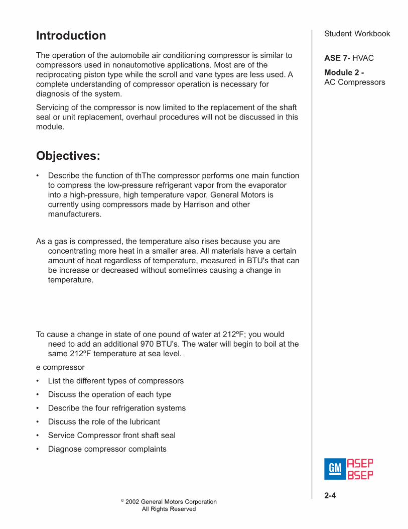
As a gas is compressed, the temperature also rises because you areconcentrating more heat in a smaller area. All materials have a certainamount of heat regardless of temperature, measured in BTU's that canbe increase or decreased without sometimes causing a change intemperature.
To cause a change in state of one pound of water at 212ºF; you wouldneed to add an additional 970 BTU's. The water will begin to boil at thesame 212ºF temperature at sea level.
e compressor• List the different types of compressors• Discuss the operation of each type• Describe the four refrigeration systems• Discuss the role of the lubricant• Service Compressor front shaft seal• Diagnose compressor complaints
© 2002 General Motors CorporationAll Rights Reserved
ASE 7- HVAC
Module 2 -AC Compressors
2-5
Student WorkbookThe compressor performs one main function to compress the low-pressure refrigerant vapor from the evaporator into a high-pressure, hightemperature vapor. General Motors is currently using compressors madeby Harrison and other manufacturers.As a gas is compressed, the temperature also rises because you areconcentrating more heat in a smaller area. All materials have a certainamount of heat regardless of temperature, measured in BTU's that can beincrease or decreased without sometimes causing a change intemperature.
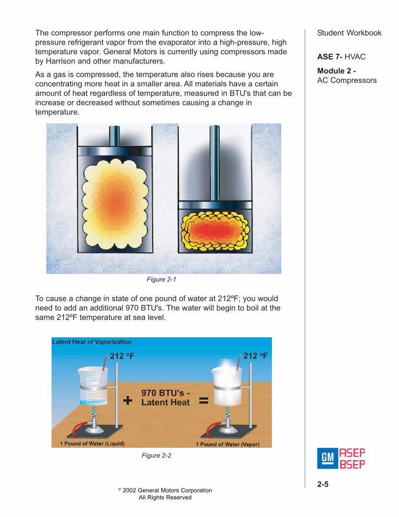
To cause a change in state of one pound of water at 212ºF; you wouldneed to add an additional 970 BTU's. The water will begin to boil at thesame 212ºF temperature at sea level.
Figure 2-1
Figure 2-2
© 2002 General Motors CorporationAll Rights Reserved
ASE 7- HVAC
Module 2 -AC Compressors
2-6
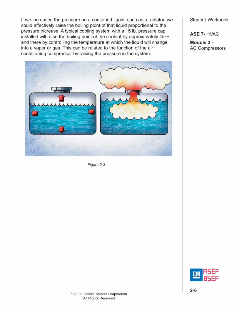
Student WorkbookIf we increased the pressure on a contained liquid, such as a radiator, wecould effectively raise the boiling point of that liquid proportional to thepressure increase. A typical cooling system with a 15 lb. pressure capinstalled will raise the boiling point of the coolant by approximately 45ºFand there by controlling the temperature at which the liquid will changeinto a vapor or gas. This can be related to the function of the airconditioning compressor by raising the pressure in the system.
Figure 2-3
© 2002 General Motors CorporationAll Rights Reserved
ASE 7- HVAC
Module 2 -AC Compressors
2-7
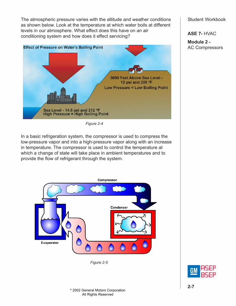
Student WorkbookThe atmospheric pressure varies with the altitude and weather conditionsas shown below. Look at the temperature at which water boils at differentlevels in our atmosphere. What effect does this have on an airconditioning system and how does it effect servicing?
In a basic refrigeration system, the compressor is used to compress thelow-pressure vapor and into a high-pressure vapor along with an increasein temperature. The compressor is used to control the temperature atwhich a change of state will take place in ambient temperatures and toprovide the flow of refrigerant through the system.
Figure 2-4
Figure 2-5
© 2002 General Motors CorporationAll Rights Reserved
ASE 7- HVAC
Module 2 -AC Compressors
2-8
Student Workbook
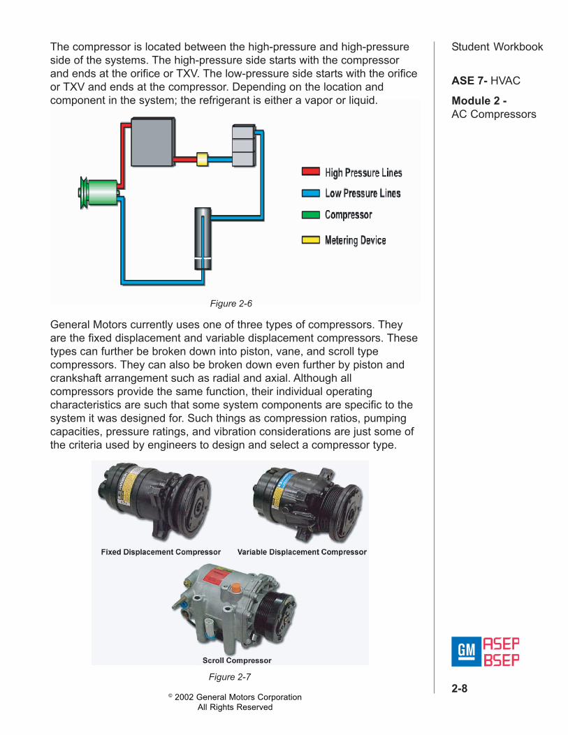
Figure 2-6
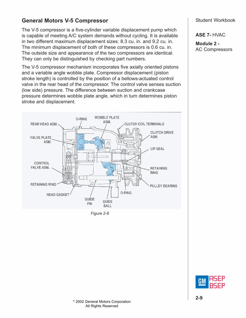
General Motors currently uses one of three types of compressors. Theyare the fixed displacement and variable displacement compressors. Thesetypes can further be broken down into piston, vane, and scroll typecompressors. They can also be broken down even further by piston andcrankshaft arrangement such as radial and axial. Although allcompressors provide the same function, their individual operatingcharacteristics are such that some system components are specific to thesystem it was designed for. Such things as compression ratios, pumpingcapacities, pressure ratings, and vibration considerations are just some ofthe criteria used by engineers to design and select a compressor type.
Figure 2-7
The compressor is located between the high-pressure and high-pressureside of the systems. The high-pressure side starts with the compressorand ends at the orifice or TXV. The low-pressure side starts with the orificeor TXV and ends at the compressor. Depending on the location andcomponent in the system; the refrigerant is either a vapor or liquid.
© 2002 General Motors CorporationAll Rights Reserved
ASE 7- HVAC
Module 2 -AC Compressors
2-9
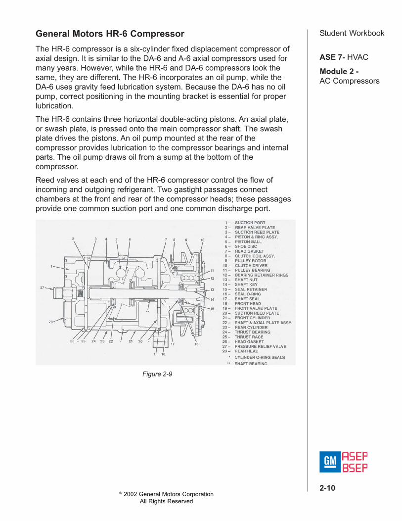
Student WorkbookGeneral Motors V-5 CompressorThe V-5 compressor is a five-cylinder variable displacement pump whichis capable of meeting A/C system demands without cycling. It is availablein two different maximum displacement sizes: 8.3 cu. in. and 9.2 cu. in.The minimum displacement of both of these compressors is 0.6 cu. in.The outside size and appearance of the two compressors are identical.They can only be distinguished by checking part numbers.The V-5 compressor mechanism incorporates five axially oriented pistonsand a variable angle wobble plate. Compressor displacement (pistonstroke length) is controlled by the position of a bellows-actuated controlvalve in the rear head of the compressor. The control valve senses suction(low side) pressure. The difference between suction and crankcasepressure determines wobble plate angle, which in turn determines pistonstroke and displacement.
Figure 2-8
© 2002 General Motors CorporationAll Rights Reserved
ASE 7- HVAC
Module 2 -AC Compressors
2-10
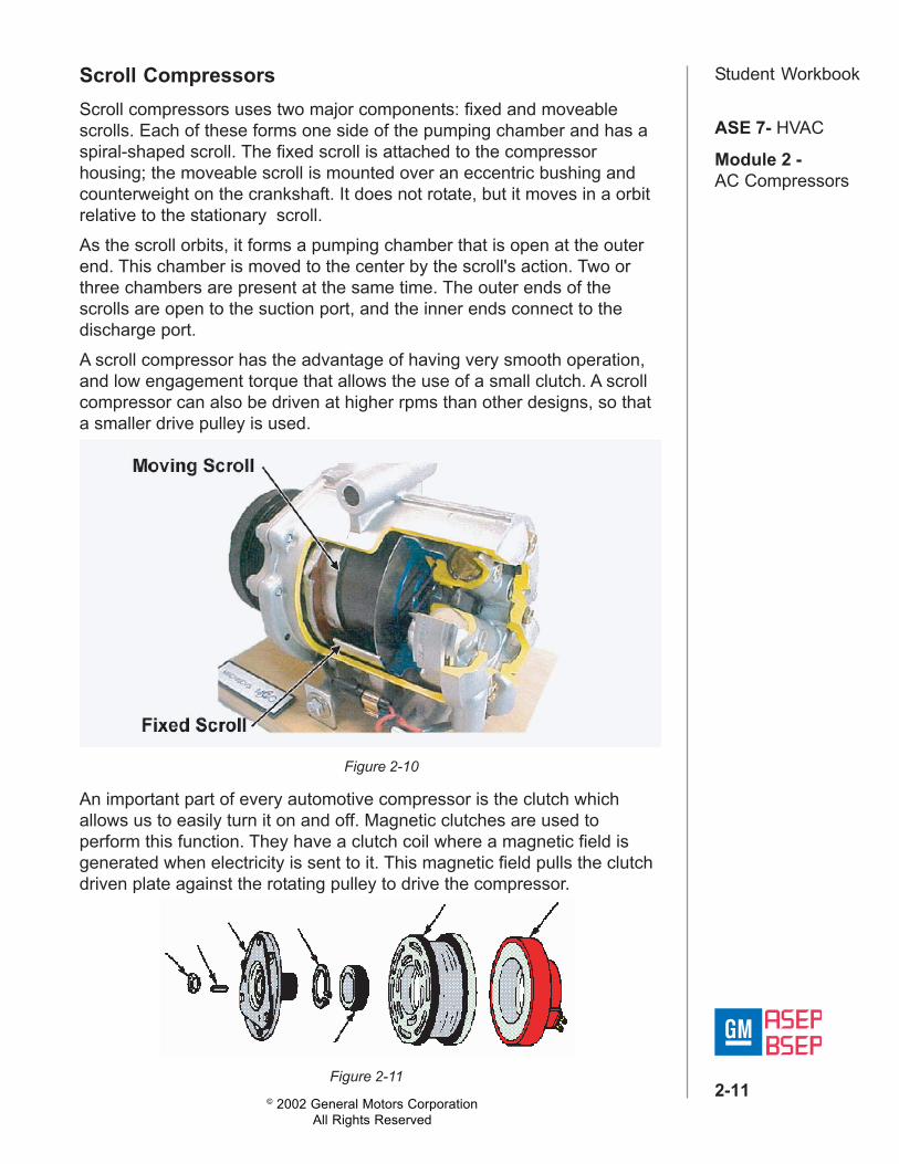
Student WorkbookGeneral Motors HR-6 CompressorThe HR-6 compressor is a six-cylinder fixed displacement compressor ofaxial design. It is similar to the DA-6 and A-6 axial compressors used formany years. However, while the HR-6 and DA-6 compressors look thesame, they are different. The HR-6 incorporates an oil pump, while theDA-6 uses gravity feed lubrication system. Because the DA-6 has no oilpump, correct positioning in the mounting bracket is essential for properlubrication.The HR-6 contains three horizontal double-acting pistons. An axial plate,or swash plate, is pressed onto the main compressor shaft. The swashplate drives the pistons. An oil pump mounted at the rear of thecompressor provides lubrication to the compressor bearings and internalparts. The oil pump draws oil from a sump at the bottom of thecompressor.Reed valves at each end of the HR-6 compressor control the flow ofincoming and outgoing refrigerant. Two gastight passages connectchambers at the front and rear of the compressor heads; these passagesprovide one common suction port and one common discharge port.
Figure 2-9
© 2002 General Motors CorporationAll Rights Reserved
ASE 7- HVAC
Module 2 -AC Compressors
2-11
Student WorkbookScroll CompressorsScroll compressors uses two major components: fixed and moveablescrolls. Each of these forms one side of the pumping chamber and has aspiral-shaped scroll. The fixed scroll is attached to the compressorhousing; the moveable scroll is mounted over an eccentric bushing andcounterweight on the crankshaft. It does not rotate, but it moves in a orbitrelative to the stationary scroll.As the scroll orbits, it forms a pumping chamber that is open at the outerend. This chamber is moved to the center by the scroll's action. Two orthree chambers are present at the same time. The outer ends of thescrolls are open to the suction port, and the inner ends connect to thedischarge port.A scroll compressor has the advantage of having very smooth operation,and low engagement torque that allows the use of a small clutch. A scrollcompressor can also be driven at higher rpms than other designs, so thata smaller drive pulley is used.
Figure 2-10
An important part of every automotive compressor is the clutch whichallows us to easily turn it on and off. Magnetic clutches are used toperform this function. They have a clutch coil where a magnetic field isgenerated when electricity is sent to it. This magnetic field pulls the clutchdriven plate against the rotating pulley to drive the compressor.
Figure 2-11
© 2002 General Motors CorporationAll Rights Reserved
ASE 7- HVAC
Module 2 -AC Compressors
2-12
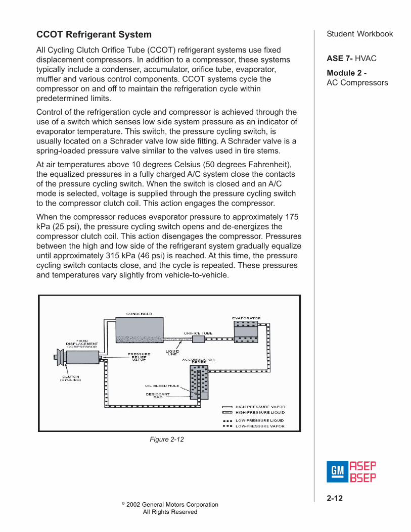
Student WorkbookCCOT Refrigerant SystemAll Cycling Clutch Orifice Tube (CCOT) refrigerant systems use fixeddisplacement compressors. In addition to a compressor, these systemstypically include a condenser, accumulator, orifice tube, evaporator,muffler and various control components. CCOT systems cycle thecompressor on and off to maintain the refrigeration cycle withinpredetermined limits.Control of the refrigeration cycle and compressor is achieved through theuse of a switch which senses low side system pressure as an indicator ofevaporator temperature. This switch, the pressure cycling switch, isusually located on a Schrader valve low side fitting. A Schrader valve is aspring-loaded pressure valve similar to the valves used in tire stems.At air temperatures above 10 degrees Celsius (50 degrees Fahrenheit),the equalized pressures in a fully charged A/C system close the contactsof the pressure cycling switch. When the switch is closed and an A/Cmode is selected, voltage is supplied through the pressure cycling switchto the compressor clutch coil. This action engages the compressor.When the compressor reduces evaporator pressure to approximately 175kPa (25 psi), the pressure cycling switch opens and de-energizes thecompressor clutch coil. This action disengages the compressor. Pressuresbetween the high and low side of the refrigerant system gradually equalizeuntil approximately 315 kPa (46 psi) is reached. At this time, the pressurecycling switch contacts close, and the cycle is repeated. These pressuresand temperatures vary slightly from vehicle-to-vehicle.
Figure 2-12
© 2002 General Motors CorporationAll Rights Reserved
ASE 7- HVAC
Module 2 -AC Compressors
2-13
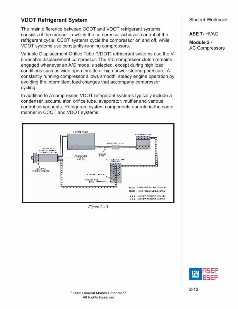
Student WorkbookVDOT Refrigerant SystemThe main difference between CCOT and VDOT refrigerant systemsconsists of the manner in which the compressor achieves control of therefrigerant cycle: CCOT systems cycle the compressor on and off, whileVDOT systems use constantly-running compressors.Variable Displacement Orifice Tube (VDOT) refrigerant systems use the V-5 variable displacement compressor. The V-5 compressor clutch remainsengaged whenever an A/C mode is selected, except during high loadconditions such as wide open throttle or high power steering pressure. Aconstantly running compressor allows smooth, steady engine operation byavoiding the intermittent load changes that accompany compressorcycling.In addition to a compressor, VDOT refrigerant systems typically include acondenser, accumulator, orifice tube, evaporator, muffler and variouscontrol components. Refrigerant system components operate in the samemanner in CCOT and VDOT systems.
Figure 2-13
© 2002 General Motors CorporationAll Rights Reserved
ASE 7- HVAC
Module 2 -AC Compressors
2-14
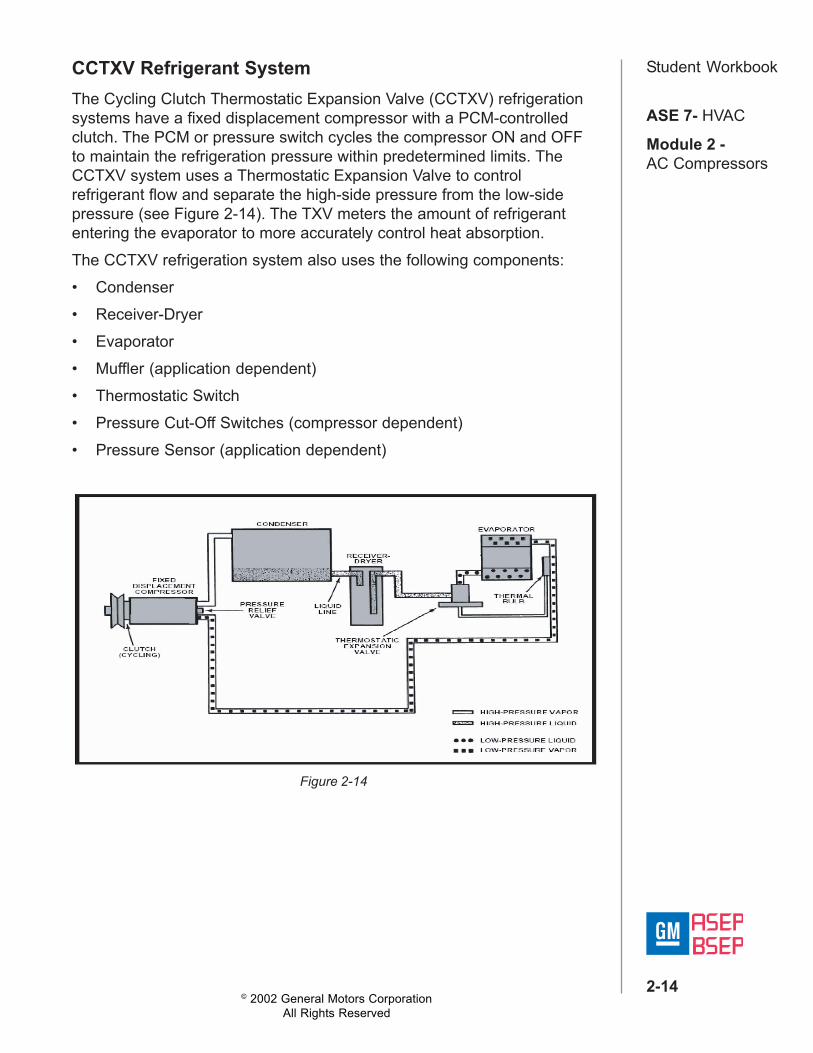
Student WorkbookCCTXV Refrigerant SystemThe Cycling Clutch Thermostatic Expansion Valve (CCTXV) refrigerationsystems have a fixed displacement compressor with a PCM-controlledclutch. The PCM or pressure switch cycles the compressor ON and OFFto maintain the refrigeration pressure within predetermined limits. TheCCTXV system uses a Thermostatic Expansion Valve to controlrefrigerant flow and separate the high-side pressure from the low-sidepressure (see Figure 2-14). The TXV meters the amount of refrigerantentering the evaporator to more accurately control heat absorption.The CCTXV refrigeration system also uses the following components:• Condenser• Receiver-Dryer• Evaporator• Muffler (application dependent)• Thermostatic Switch• Pressure Cut-Off Switches (compressor dependent)• Pressure Sensor (application dependent)
Figure 2-14
© 2002 General Motors CorporationAll Rights Reserved
ASE 7- HVAC
Module 2 -AC Compressors
2-15
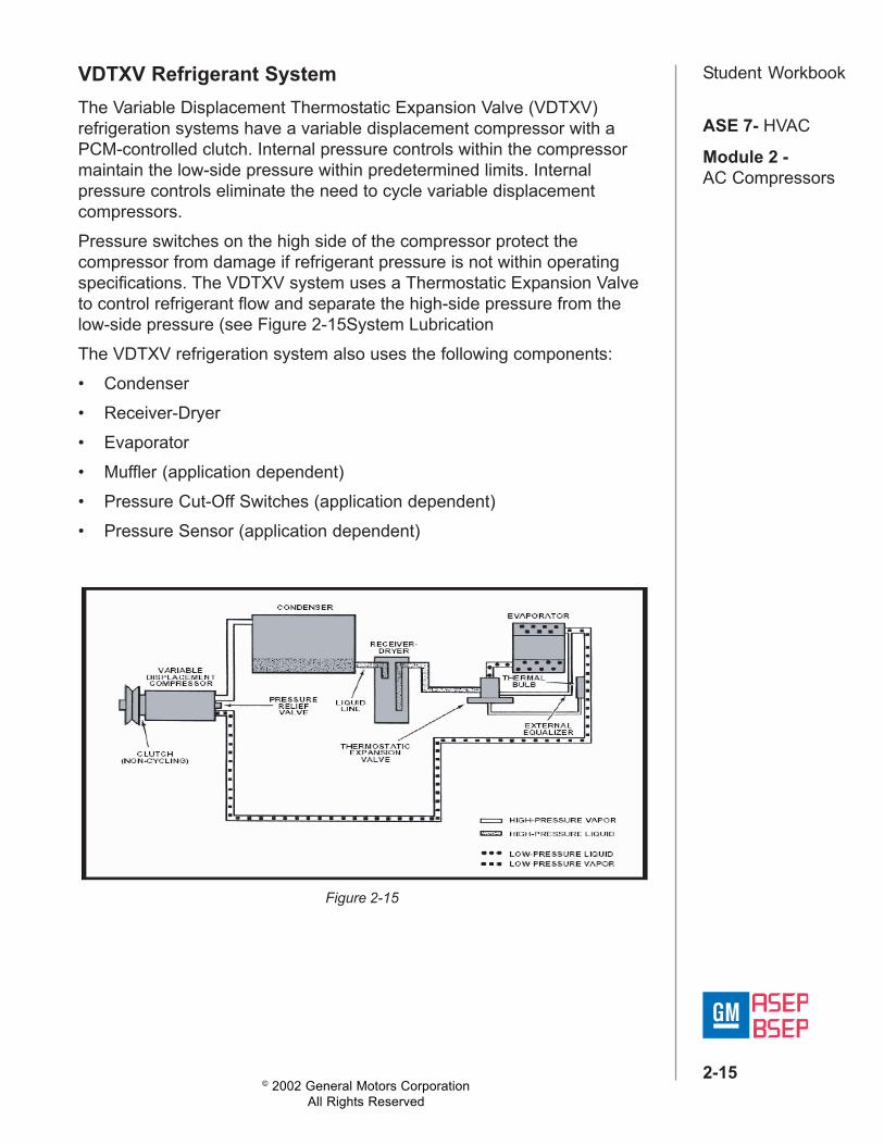
Student WorkbookVDTXV Refrigerant SystemThe Variable Displacement Thermostatic Expansion Valve (VDTXV)refrigeration systems have a variable displacement compressor with aPCM-controlled clutch. Internal pressure controls within the compressormaintain the low-side pressure within predetermined limits. Internalpressure controls eliminate the need to cycle variable displacementcompressors.Pressure switches on the high side of the compressor protect thecompressor from damage if refrigerant pressure is not within operatingspecifications. The VDTXV system uses a Thermostatic Expansion Valveto control refrigerant flow and separate the high-side pressure from thelow-side pressure (see Figure 2-15System LubricationThe VDTXV refrigeration system also uses the following components:• Condenser• Receiver-Dryer• Evaporator• Muffler (application dependent)• Pressure Cut-Off Switches (application dependent)• Pressure Sensor (application dependent)
Figure 2-15
© 2002 General Motors CorporationAll Rights Reserved
ASE 7- HVAC
Module 2 -AC Compressors
2-16
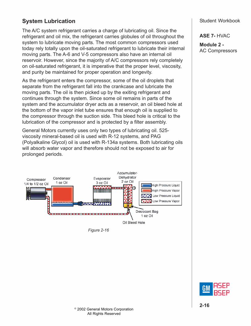
Student WorkbookSystem LubricationThe A/C system refrigerant carries a charge of lubricating oil. Since therefrigerant and oil mix, the refrigerant carries globules of oil throughout thesystem to lubricate moving parts. The most common compressors usedtoday rely totally upon the oil-saturated refrigerant to lubricate their internalmoving parts. The A-6 and V-5 compressors also have an internal oilreservoir. However, since the majority of A/C compressors rely completelyon oil-saturated refrigerant, it is imperative that the proper level, viscosity,and purity be maintained for proper operation and longevity.As the refrigerant enters the compressor, some of the oil droplets thatseparate from the refrigerant fall into the crankcase and lubricate themoving parts. The oil is then picked up by the exiting refrigerant andcontinues through the system. Since some oil remains in parts of thesystem and the accumulator dryer acts as a reservoir, an oil bleed hole atthe bottom of the vapor inlet tube ensures that enough oil is supplied tothe compressor through the suction side. This bleed hole is critical to thelubrication of the compressor and is protected by a filter assembly.General Motors currently uses only two types of lubricating oil. 525-viscosity mineral-based oil is used with R-12 systems, and PAG(Polyalkaline Glycol) oil is used with R-134a systems. Both lubricating oilswill absorb water vapor and therefore should not be exposed to air forprolonged periods.
Figure 2-16