ASE 6 - Electrical Electronic...
64
ASE 6 - Electrical Electronic Systems Module 10 Operation of Automotive Electrical Components & Wire Repair
Transcript of ASE 6 - Electrical Electronic...

ASE 6 - Electrical ElectronicSystems
Module 10Operation of Automotive Electrical
Components & Wire Repair

AcknowledgementsGeneral Motors, the IAGMASEP Association Board of Directors, and RaytheonProfessional Services, GM's training partner for GM's Service Technical College wish tothank all of the people who contributed to the GM ASEP/BSEP curriculum developmentproject 2002-3. This project would not have been possible without the tireless efforts ofmany people. We acknowledge:
• The IAGMASEP Association members for agreeing to tackle this large project tocreate the curriculum for the GM ASEP/BSEP schools.
• The IAGMASEP Curriculum team for leading the members to a single vision andimplementation.
• Direct contributors within Raytheon Professional Services for their support oftranslating a good idea into reality. Specifically, we thank:
– Chris Mason and Vince Williams, for their leadership, guidance, and support.– Media and Graphics department under Mary McClain and in particular, Cheryl
Squicciarini, Diana Pajewski, Lesley McCowey, Jeremy Pawelek, & NancyDeSantis.
– For his help on the Electrical curriculum volume, Subject Matter Expert, KenBeish, Jr., for his wealth of knowledge.
Finally, we wish to recognize the individual instructors and staffs of the GM ASEP/BSEPColleges for their contribution for reformatting existing General Motors training material,adding critical technical content and the sharing of their expertise in the GM product.Separate committees worked on each of the eight curriculum areas. For the work on thisvolume, we thank the members of the Electrical committee:
– Jack Davis, Community College of Baltimore County - Catonsville– Jim Halderman, Sinclair Community College– Megan Kuehm, Community College of Allegheny County– Frank Longbottom, Camden County College– Jeff Rehkopf, Florida Community College at Jacksonville– Randy Peters, Des Moines Area Community College– David Rodriguez, College of Southern Idaho– Ed Schauffler, Longview Community College– Vince Williams, Raytheon

ContentsModule 10 – Operation of Automotive ElectricalComponents & Wire RepairAcknowledgements .......................................................................................... 2Objectives ........................................................................................................ 5
Lesson 1. Review of Circuit Faults ................................................................................. 6Open Circuits .................................................................................................................. 6Shorts To Ground ............................................................................................................ 8Shorts to Power .............................................................................................................. 9Resistance Too High ..................................................................................................... 10Resistance Too Low ...................................................................................................... 10Exercise 10-1 .................................................................................................................11Lesson 2. Operation of Automotive Electrical Components .......................................... 13Wires............................................................................................................................. 13Wire Harnesses ............................................................................................................ 14Wire Harness Zoning .................................................................................................... 15Wire Gage..................................................................................................................... 16Exercise 10-2 ................................................................................................................ 18Wire Repair Techniques ................................................................................................ 20Stripping ........................................................................................................................ 20Crimping ....................................................................................................................... 21Sealed Splice Crimp Matrix ........................................................................................... 24Soldering ....................................................................................................................... 25Taping ........................................................................................................................... 27Crimp and Seal Splice Sleeve ...................................................................................... 27UT-100A Ignition Instructions ........................................................................................ 28Terminals ...................................................................................................................... 29Connectors ................................................................................................................... 30Releasing Terminals from Connectors .......................................................................... 31Grommets ..................................................................................................................... 32Sockets ......................................................................................................................... 32

Exercise 10-3 ................................................................................................................ 35Switches........................................................................................................................ 37Circuit Protectors .......................................................................................................... 38Fuses ............................................................................................................................ 38Fusible Links ................................................................................................................. 39Circuit Breakers ............................................................................................................ 40Exercise 10-4 ................................................................................................................ 41Resistors ....................................................................................................................... 43Resistors and Wattage.................................................................................................. 44Variable Resistors ......................................................................................................... 46Rheostats ...................................................................................................................... 46Potentiometers .............................................................................................................. 47Thermistors ................................................................................................................... 48Failed Resistors ............................................................................................................ 48Exercise 10-5 ................................................................................................................ 49Experiment 10-2 ........................................................................................................... 52Experiment 10-3 ........................................................................................................... 54Capacitors ..................................................................................................................... 55Capacitor Energy Storage ............................................................................................. 55Units of Measurement ................................................................................................... 56Calculating Total Capacitance ....................................................................................... 56Experiment 10-4 ........................................................................................................... 58Capacitor Filter .............................................................................................................. 59Experiment 10-5 ........................................................................................................... 60Capacitor Timer............................................................................................................. 61Experiment 10-6 ........................................................................................................... 62Exercise 10-6 ................................................................................................................ 64

© 2002 General Motors CorporationAll Rights Reserved
ASE 6 - ElectricalElectronic Systems
Module 10 -Operation ofAutomotiveElectricalComponents &Wire Repair
10-5
Student WorkbookObjectivesAt the end of this section, the technician will be able to do the followingtasks:
NATEF Area VI. A.Inspect and test fusible links, circuit breakers, and fuses; determinenecessary action.Inspect and test switches, connectors, relays, solid state devices, andwires of electrical/electronic circuits; perform necessary action.Repair wiring harnesses and connectors.Perform solder repair of electrical wiring.
STC Tasks:Describe the characteristics of wiring used in automotive circuitsDescribe the characteristics of electrical wire terminals and connectorsIdentify the characteristics of wire grommetsIdentify the characteristics of automotive wiring socketsIdentify the techniques used in wire stripping, crimping, and solderingIdentify techniques used to apply heat shrink tubing and taping wireconnectionsIdentify the characteristics of automotive electrical switchesIdentify the characteristics of electrical circuit protectorsIdentify various types of resistorsIdentify the characteristics of fixed resistorsIdentify the characteristics of variable resistorsIdentify the characteristics of capacitors used in automotive electricalcircuits

© 2002 General Motors CorporationAll Rights Reserved
ASE 6 - ElectricalElectronic Systems
Module 10 -Operation ofAutomotiveElectricalComponents &Wire Repair
10-6
Student WorkbookLesson 1. Review of Circuit FaultsObjectiveReview basic circuit faults (open circuits, shorts to ground, shorts topower, resistance problems) and their symptoms.
Open CircuitsAn open is a break in a circuit. Opens prevent current flow, and canprevent the operation of loads. Opens can occur anywhere in a circuit, butpoor electrical connections are the most common cause of opens.Some opens are intentional, such as a switch in the OFF position. Otheropens are the result of proper operation of the component that hascaused the open, such as a fuse that has opened to prevent circuitdamage. Finally, some opens are the result of component failure, such asa wire with cracked insulation, or a lamp with a burned out filament.An open in a series circuit will affect all loads in that circuit.
Figure 10-1, Open in a Series Circuit

© 2002 General Motors CorporationAll Rights Reserved
ASE 6 - ElectricalElectronic Systems
Module 10 -Operation ofAutomotiveElectricalComponents &Wire Repair
10-7
Student WorkbookAn open in the main line of a parallel circuit (Point A) will also affect allloads in the circuit, while an open in one branch of a parallel circuit (PointB) will only affect loads on the branch in which the open occurs.
Note:Some opens are obvious and visible, such as a broken wire. Others canbe hidden; a defective resistor, for instance, would not be immediatelyobvious.
Figure 10-2, Opens in a Parallel Circuit

© 2002 General Motors CorporationAll Rights Reserved
ASE 6 - ElectricalElectronic Systems
Module 10 -Operation ofAutomotiveElectricalComponents &Wire Repair
10-8
Student WorkbookShorts To GroundA short to ground occurs when current flow is grounded before it wasintended to be. This usually happens when wire insulation breaks and thewire touches a ground.In Figure 10-3, the short in View A occurs after the switch and before theload. In such a case, because the load is not resisting current flow in thecircuit, resistance is lowered, and the increased current flow will open thefuse or other circuit protector. Without a circuit protector, the wire mightbecome hot enough to burn.In View B, the short to ground is after the load and before the switch. Theswitch is bypassed in the circuit, making the circuit always closed. Thebulb is lit all of the time.
Figure 10-3, Shorts to Ground

© 2002 General Motors CorporationAll Rights Reserved
ASE 6 - ElectricalElectronic Systems
Module 10 -Operation ofAutomotiveElectricalComponents &Wire Repair
10-9
Student WorkbookShorts to PowerA short to power (also called a short to voltage) occurs when one circuit isshorted to the voltage of another circuit. Such a short can also occurbetween two separate branches of the same circuit. The cause is usuallybroken or damaged wire insulation.The symptoms of a short to power depend on the location of the short inboth circuits. In View A, the short is before the switches on both circuits.When a short such as this occurs, both switches will control both circuits.In View B, the short is before the switches in both branches of the circuit,and before the load on one branch. Switch A will blow the circuit fuse,because its load is out of the circuit. Switch B will control only the load onits circuit branch.
Figure 10-4, Shorts to Power

© 2002 General Motors CorporationAll Rights Reserved
ASE 6 - ElectricalElectronic Systems
Module 10 -Operation ofAutomotiveElectricalComponents &Wire Repair
10-10
Student WorkbookResistance Too HighHigh resistance in a circuit is usually caused by corrosion or dirt at aconnection, or by damaged wires. When resistance is high, a circuit’sloads may operate improperly; a bulb may glow dimly or flicker, forinstance, or a motor may run slower than usual. If resistance is highenough, loads may not function at all.High resistance in a circuit can be measured with a DMM. A voltage droptest performed at various points along the circuit will help you locate highresistance connections. Alternatively, you can use the ΩΩΩΩΩ setting and placethe test probes at two points through which current should be able to flow.If the meter shows infinite or extremely high resistance (ohms), there is nocontinuity.
Note: Do not perform a continuity test on an Electrostatic Discharge(ESD) sensitive device.
Resistance Too LowIf there is too little resistance, and voltage remains constant, thenamperage will rise. This can damage circuit components, such as wires,circuit protection and circuit controllers.Low resistance is usually caused by faulty or missing resistors or loads.

© 2002 General Motors CorporationAll Rights Reserved
ASE 6 - ElectricalElectronic Systems
Module 10 -Operation ofAutomotiveElectricalComponents &Wire Repair
10-11
Student WorkbookExercise 10-1Read each question carefully and choose the correct response.
1. In a series circuit, any open willa. cause current to stop flowingb. cause an increase in current flowc. cause an intermittent failured. have no effect
2. An open in one branch of a parallel circuit will _______a. cause failure of current flow in all branchesb. cause failure of current flow in the branch which is openc. cause the fuse to blowd. cause no problems
3. Which of the following cannot cause an open?a. loose connectionsb. corroded connectionsc. too much solderd. broken wires
4. If a short to ______ occurs before a load that load will not function.a. powerb. openc. groundd. resistance
© 2002 General Motors CorporationAll Rights Reserved
ASE 6 - ElectricalElectronic Systems
Module 10 -Operation ofAutomotiveElectricalComponents &Wire Repair
10-12
Student Workbook5. A short to power can do which of the following:a. cause switches to control loads on other circuitsb. cause loads on some circuits to behave normally, while other loads
do not operatec. both a and bd. neither a nor b
6. If resistance is too high, which of the following may not occur:a. a bulb may light dimlyb. a bulb may not light at allc. a bulb may blow outd. a motor may run slowly
7. Low resistance in a circuit can damage circuit components.a. Trueb. False

© 2002 General Motors CorporationAll Rights Reserved
ASE 6 - ElectricalElectronic Systems
Module 10 -Operation ofAutomotiveElectricalComponents &Wire Repair
10-13
Student WorkbookLesson 2. Operation of Automotive Electrical ComponentsObjective• Familiarize students with components commonly found in automotive
circuits, such as wires, connectors, and capacitors• Demonstrate wire repair techniques• Familiarize students with electrical component operation
WiresWires are the conductors for electrical circuits. Wires are also calledleads.Most wires are stranded (made up of several smaller wires that arewrapped together and covered by a common insulating sheath).There are many types of wires found in General Motors automobiles,including:
• Copper — the most common type. Copper wires are usually stranded.• Fusible Links — circuit protection devices that are made of smaller
wire than the rest of the circuit they protect.• Twisted/Shielded Cable — a pair of small gage wires insulated against
RFI/EMI, used for computer communication signals• Ribbon Cable — copper wires laid out on a plastic “backing,” used in
areas where space is tight, such as the BCM connector on the GMCYukon.
• Hiflex — 266 strand wire used in ABS systems

© 2002 General Motors CorporationAll Rights Reserved
ASE 6 - ElectricalElectronic Systems
Module 10 -Operation ofAutomotiveElectricalComponents &Wire Repair
10-14
Student Workbook
Figure 10-5, Examples of Various Types of Wire (not to scale)
Wire HarnessesMany wires are bound together in groups with one or more commonconnectors on each end. These groups are called wire harnesses. Notethat a harness may contain wires from different circuits and systems. Anexample would be the harness that plugs into the headlight switchassembly, which contains wires for parking lights, tail-lights, and low- andhigh-beam headlights, among others.Some harness wires are enclosed in plastic conduit. These conduits aresplit lengthwise to allow easy access to the harness wires. Other harnesswires are wrapped in tape. Clips (plastic) and clamps (metal) attachharnesses to the vehicle.Service Manuals have harness routing guides to help you easily locate aspecific harness.

© 2002 General Motors CorporationAll Rights Reserved
ASE 6 - ElectricalElectronic Systems
Module 10 -Operation ofAutomotiveElectricalComponents &Wire Repair
10-15
Student Workbook
Figure 10-6, Typical Harness Routing View
Wire Harness ZoningAll grounds, in-line connections, pass-through grommets, and splices areidentified in routing views and other areas by zones, codes which tell youthe location of the harness in the vehicle. Components with numbers inthe 100 range are all located in the engine bay, for instance, while those inthe 400 range are in the trunk area. Some vehicles do not have all zones;a Corvette will not have 700 or 800 zones, since these zones designatecompo-nents found in the left and right rear doors, respectively, of a fourdoor vehicle.
© 2002 General Motors CorporationAll Rights Reserved
ASE 6 - ElectricalElectronic Systems
Module 10 -Operation ofAutomotiveElectricalComponents &Wire Repair
10-16
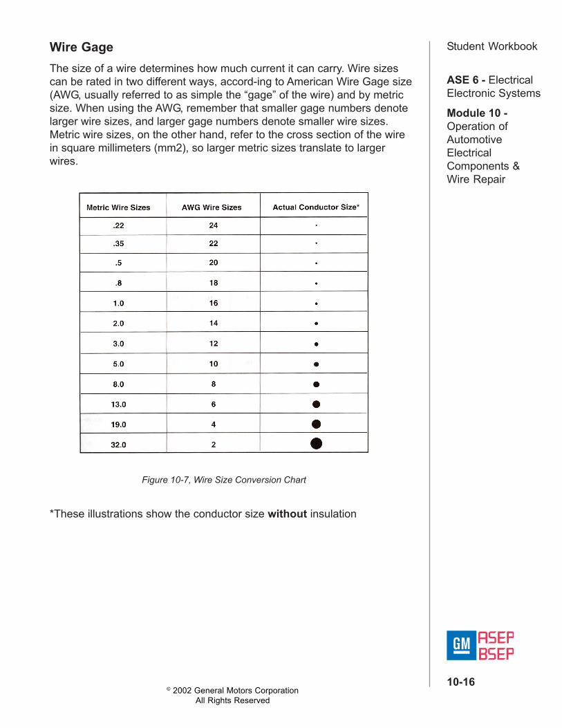
Student WorkbookWire GageThe size of a wire determines how much current it can carry. Wire sizescan be rated in two different ways, accord-ing to American Wire Gage size(AWG, usually referred to as simple the “gage” of the wire) and by metricsize. When using the AWG, remember that smaller gage numbers denotelarger wire sizes, and larger gage numbers denote smaller wire sizes.Metric wire sizes, on the other hand, refer to the cross section of the wirein square millimeters (mm2), so larger metric sizes translate to largerwires.
Figure 10-7, Wire Size Conversion Chart
*These illustrations show the conductor size without insulation

© 2002 General Motors CorporationAll Rights Reserved
ASE 6 - ElectricalElectronic Systems
Module 10 -Operation ofAutomotiveElectricalComponents &Wire Repair
10-17
Student WorkbookResistance increases as wire length increases. Because of this, as therequired length of a wire increases, the wire size must increase toaccommodate the required current. The table below yields the requiredgage for a given length of wire and a given circuit amperage for 12 voltsystems.
Figure 10-8, Wire Gage Requirements for Circuit Length and Amperage

© 2002 General Motors CorporationAll Rights Reserved
ASE 6 - ElectricalElectronic Systems
Module 10 -Operation ofAutomotiveElectricalComponents &Wire Repair
10-18
Student WorkbookExercise 10-2Read each question carefully and choose the correct response.
1. Which of the following is the most common type of wire use in anautomobile?a. Copperb. lsolinearc. ribbon cabled. twisted/shielded
2. A ___________ is a group of wires that are bound together.a. routeb. harnessc. guided. clip
3. ___________ and ___________ are the two methods of measuringwire size.a. standard, oddb. usual, corec. metric, AWGd. metric, gage
© 2002 General Motors CorporationAll Rights Reserved
ASE 6 - ElectricalElectronic Systems
Module 10 -Operation ofAutomotiveElectricalComponents &Wire Repair
10-19
Student Workbook4. When referring to AWG wire gages, a ___________ number denotes a_________wire size, and vice versa.a. larger, largerb. smaller, smallerc. denser, longerd. larger, smaller
5. As wire length increases, ___________ increases.a. resistanceb. amperagec. wattaged. gauge
6. Convert the following AWG wire sizes to metric sizes.a No. 18 _________b. No. 12 _________c. No. 10 _________d. No. 22 _________
7. The larger the AWG number, the _____________________ currentthe wire can carry.

© 2002 General Motors CorporationAll Rights Reserved
ASE 6 - ElectricalElectronic Systems
Module 10 -Operation ofAutomotiveElectricalComponents &Wire Repair
10-20
Student WorkbookWire Repair TechniquesStrippingWhen you must create a new connection to a terminal, or join two or morewires together, the wire(s) should be stripped. You should never “ring cut”a wire (cut around the outside of the insulation with a knife). This can nickor cut individual strands, and reduce the amount of current the wire cancarry.The correct way to strip a wire is with a wire stripper. The stripper isdesigned to remove only wire insulation, not wire. Also, the stripper will notstretch the wire strands, which could reduce the amount of current thewire can carry.When using a stripper, feed the wire until it is seated against the guide,and then make sure that the gripper has engaged the wire firmly beforeclosing the handles.If you must strip more than one wire (such as two wires leading from thesame connector), be sure to cut them both to the same length beforestripping them.
Note: Strippers and other electrical tools are supplied to GM by Kent-Moore.
Figure 10-9, Wire Stripper

© 2002 General Motors CorporationAll Rights Reserved
ASE 6 - ElectricalElectronic Systems
Module 10 -Operation ofAutomotiveElectricalComponents &Wire Repair
10-21
Student WorkbookCrimpingCrimping is the technique used to join two or more wires and/or terminalstogether. Do not twist wires together, as this type of repair will not last forlong. Also, avoid using pliers to crimp terminals or splice clips; the properway to crimp a wire is with a crimping tool. The crimping tool is designedto apply the proper amount of force to close a terminal’s or clip’s wingsaround the conductor and insulator being joined so that neither isdamaged.
Note: Wires that are exposed to weather should be joined with a specialseal splice sleeve to protect them from dirt and moisture.
Different tools are used to crimp terminals and splice clips.
To use the Terminal Crimp Tool:
1. Compress the tool handles until the ratchet automatically opens thejaws.
2. Determine the correct holder per the crimp matrix for core crimp.3. Core wings should be crimped first. Lay the back of the terminal core
wings on the appropriate anvil. Be sure the core wings are pointingtowards the forming jaws.
Figure 10-10, Terminal Crimp Tools
© 2002 General Motors CorporationAll Rights Reserved
ASE 6 - ElectricalElectronic Systems
Module 10 -Operation ofAutomotiveElectricalComponents &Wire Repair
10-22
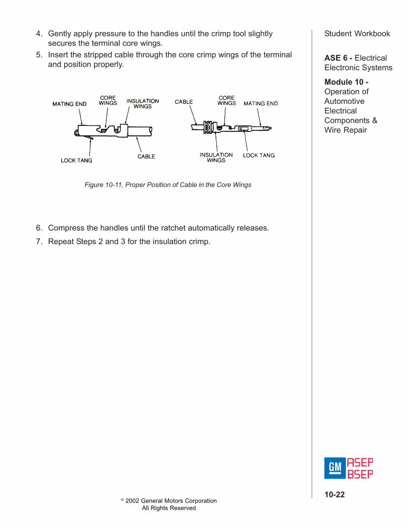
Student Workbook4. Gently apply pressure to the handles until the crimp tool slightlysecures the terminal core wings.
5. Insert the stripped cable through the core crimp wings of the terminaland position properly.
6. Compress the handles until the ratchet automatically releases.7. Repeat Steps 2 and 3 for the insulation crimp.
Figure 10-11, Proper Position of Cable in the Core Wings
© 2002 General Motors CorporationAll Rights Reserved
ASE 6 - ElectricalElectronic Systems
Module 10 -Operation ofAutomotiveElectricalComponents &Wire Repair
10-23
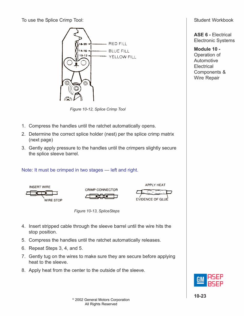
Student WorkbookTo use the Splice Crimp Tool:
1. Compress the handles until the ratchet automatically opens.2. Determine the correct splice holder (nest) per the splice crimp matrix
(next page)3. Gently apply pressure to the handles until the crimpers slightly secure
the splice sleeve barrel.
Note: It must be crimped in two stages — left and right.
Figure 10-12, Splice Crimp Tool
Figure 10-13, SpliceSteps
4. Insert stripped cable through the sleeve barrel until the wire hits thestop position.
5. Compress the handles until the ratchet automatically releases.6. Repeat Steps 3, 4, and 5.7. Gently tug on the wires to make sure they are secure before applying
heat to the sleeve.8. Apply heat from the center to the outside of the sleeve.

© 2002 General Motors CorporationAll Rights Reserved
ASE 6 - ElectricalElectronic Systems
Module 10 -Operation ofAutomotiveElectricalComponents &Wire Repair
10-24
Student WorkbookSealed Splice Crimp Matrix
Crimping makes a mechanical connection between the wires being joined,but it should not be expected to make an electrical connection. Once thewires are crimped, they should be soldered.
Figure 10-14, Workmanship Standards for Terminal Crimping

© 2002 General Motors CorporationAll Rights Reserved
ASE 6 - ElectricalElectronic Systems
Module 10 -Operation ofAutomotiveElectricalComponents &Wire Repair
10-25
Student Workbook
Figure 10-15, Soldering Equipment
SolderingWhile an electrical connection might exist between a wire and a terminalor two wires, it might be incomplete and/or faulty. Soldering creates adependable electrical connection.When soldering, follow these guidelines:• Use the soldering tool to heat the terminal or clip. This will transfer
heat by conductance to the wires, which will become hot enough tomelt the solder. Do not heat the solder directly.
• Make sure that there are solder fillets between the core (conductor)and the terminal or clip, but not on the insulator
• If using a clip, make sure that the solder covers the exposedconductor, and all of the clip.
• If soldering around a terminal, make sure the solder covers theconductor, but does not extend past the conductor. (It may be helpfulto tilt the terminal end of the wire being repaired slightly up to preventsolder from flowing onto the terminal.)
• Do not apply so much solder that the individual wire strands aren’tvisible.
• Do not allow the soldering tool to burn the terminal or insulation.• Do not leave sharp points of solder; these can tear tape used to
insulate the repair.• Do not allow individual wire strands to protrude from the repair, or to
protrude over the insulator.• Do not solder wires in a live circuit. Always disconnect power from
wires and then make the repair.
Note: Some new 02 sensors draw oxygen through the wire. Alwaysconsult a brand specific service manual before servicing an 02 sensorlead.

© 2002 General Motors CorporationAll Rights Reserved
ASE 6 - ElectricalElectronic Systems
Module 10 -Operation ofAutomotiveElectricalComponents &Wire Repair
10-26
Student Workbook
Figure 10-16, Workmanship Standards for Soldering

© 2002 General Motors CorporationAll Rights Reserved
ASE 6 - ElectricalElectronic Systems
Module 10 -Operation ofAutomotiveElectricalComponents &Wire Repair
10-27
Student WorkbookTapingTaping is the final step in a wire repair. Taping provides insulation for thenew connection, and protects the wire splice from damage.When taping a splice, make sure the tape is rolled smooth and flat. Don’tleave any “tape flags” that can snag on components and begin to peelaway the tape. Delphi Packard recommends splice tape, which should beapplied in squares of approximately 2 inches.
Figure 10-17, Workmanship Standards for Taping
Crimp and Seal Splice SleeveGM requires the use of crimp and seal tubing for repairs to wires that areexposed to the elements. To use heat shrink tubing, first cut a section oftubing of an appropriate length and slide it onto one of the wires beingrepaired. Crimp as usual, then slide the crimp and seal tubing over thesplice. Apply heat to the tubing, and once it starts to shrink, rotate the wireto get even heating and shrinking. Finally, apply heat to the ends of thetubing until melted adhesive is visible on the wire outside the tube.
Figure 10-18, Workmanship Standards for Crimp and Seal Splice Sleeve Application
Note: Twisted/Shielded Cables require special repair techniques. SeeService Manual for details.

© 2002 General Motors CorporationAll Rights Reserved
ASE 6 - ElectricalElectronic Systems
Module 10 -Operation ofAutomotiveElectricalComponents &Wire Repair
10-28
Student WorkbookUT-100A Ignition Instructions
1. For UT-100A only, pull off the protective cap. Do not twist it off.2. Open the ignition vent by lowering the shutter lever. Do not touch the
hot air exhaust opening.3. Position the gas control lever to 3. (Set at a lower setting when in a hot
room, and at a higher setting in a cooler room.)4. Turn ON/OFF lever to the ON position and ignite at ignition vent
(Step A).5. Wait until a glow is seen at the catalyst (seen through the ignition vent
after about 4-5 seconds).6. Close the ignition vent completely by raising the shutter lever (Step B).
The flame will go out and the gas will react with the catalyst producingheat.
7. The heat of the soldering or heat tip (whichever is being used) can becontrolled by the gas control lever (Step C).
8. Extinguish by turning the gas ON/OFF lever to OFF (Step D).
Figure 10-19, UT-100A Ultratorch

© 2002 General Motors CorporationAll Rights Reserved
ASE 6 - ElectricalElectronic Systems
Module 10 -Operation ofAutomotiveElectricalComponents &Wire Repair
10-29
Student WorkbookTerminalsThe metal piece attached to the end of a wire is called a terminal.Although terminals are sometimes referred to as connectors, it’s moreaccurate to think of a terminal as part of a wire, rather than part of aconnector.There are several series of terminals in use in GM automobiles, includingMetri-Pack, Micro-Pack, Weather Pack (used for applications that will beexposed to the elements), Pack-Con, Pin Grip, tangless 1 00-W, Metri-Pack tangless, and GT terminals. Also, some terminals are “pull-to-seat,”meaning that the terminal must be pulled into its connector from the sidewith the mating face, while others are “push-to-seat,’ meaning that theymust be pushed into the connector on the opposite side of the matingface. Note that, when using a “pull-to-seat” terminal, the wire must bethreaded through the connector before the terminals are crimped to thewire. Reference informa-tion is available from Delphi Packard.Most terminals have a) one or more lock tangs, which lock the terminalinto a connector, b) core wings, which are crimped over the conductor, c)insulation wings, which are crimped over the insulation. Tanglessterminals, such as the Micro-Pack 100W and some of the Metri-Packseries, have no tangs; part of the connector serves a similar function forthese terminals.
Figure 10-20, Parts of a Typical Connector

© 2002 General Motors CorporationAll Rights Reserved
ASE 6 - ElectricalElectronic Systems
Module 10 -Operation ofAutomotiveElectricalComponents &Wire Repair
10-30
Student WorkbookConnectorsTerminals fit into connectors, which are the plastic components used toprovide the mechanical connection for a circuit when fitted to a matingconnector. Two mating connectors (which can be called “male” and“female”) are said to make a single connection.A single connector might hold a single terminal or it might hold many.When it holds more than one terminal, a connector is called a multi-cavityconnector.Some connectors also have CPA (connector position assurance), plastictabs that lock the male and female connectors together, and/or TPA(terminal position assurance), tabs that lock the terminals in place insidethe connector.
© 2002 General Motors CorporationAll Rights Reserved
ASE 6 - ElectricalElectronic Systems
Module 10 -Operation ofAutomotiveElectricalComponents &Wire Repair
10-31
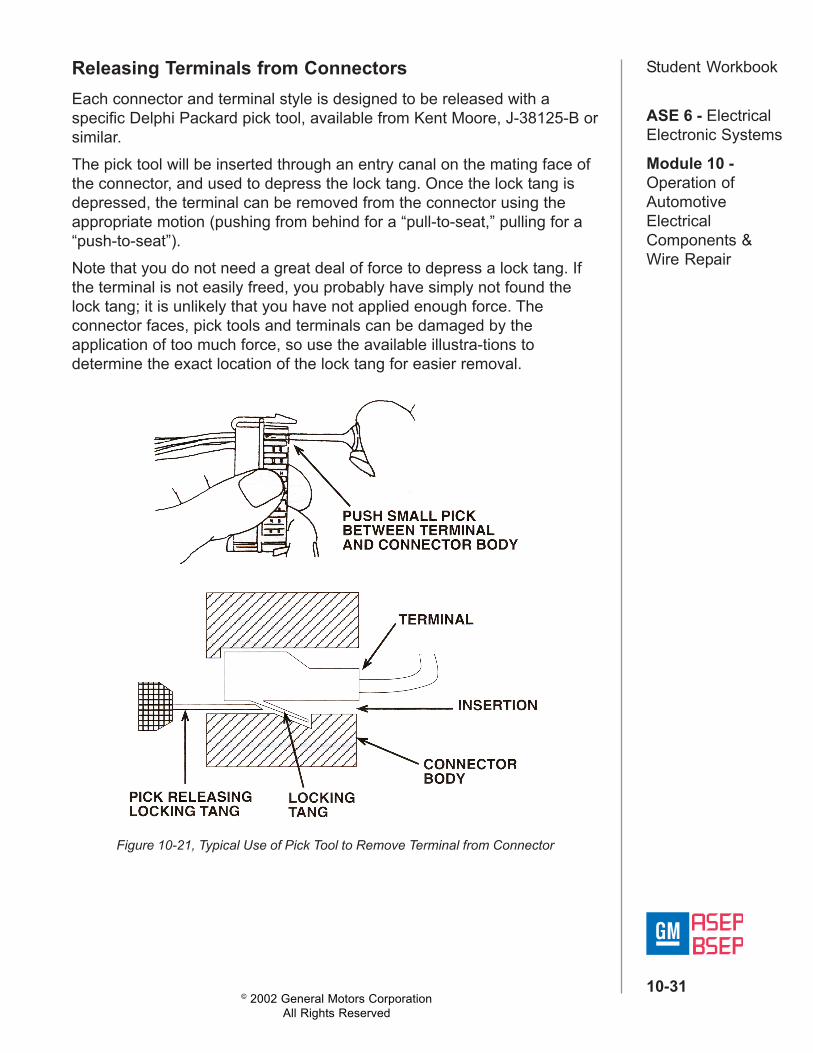
Student WorkbookReleasing Terminals from ConnectorsEach connector and terminal style is designed to be released with aspecific Delphi Packard pick tool, available from Kent Moore, J-38125-B orsimilar.The pick tool will be inserted through an entry canal on the mating face ofthe connector, and used to depress the lock tang. Once the lock tang isdepressed, the terminal can be removed from the connector using theappropriate motion (pushing from behind for a “pull-to-seat,” pulling for a“push-to-seat”).Note that you do not need a great deal of force to depress a lock tang. Ifthe terminal is not easily freed, you probably have simply not found thelock tang; it is unlikely that you have not applied enough force. Theconnector faces, pick tools and terminals can be damaged by theapplication of too much force, so use the available illustra-tions todetermine the exact location of the lock tang for easier removal.
Figure 10-21, Typical Use of Pick Tool to Remove Terminal from Connector

© 2002 General Motors CorporationAll Rights Reserved
ASE 6 - ElectricalElectronic Systems
Module 10 -Operation ofAutomotiveElectricalComponents &Wire Repair
10-32
Student WorkbookGrommetsGrommets provide a sealed transition between two different environments,e.g. between the engine compartment and passenger compartment.Grommets are made of either rubber or plastic.Grommets are identified on schematics using the symbol illustrated below.The proper identification of grommets can help you in tracing circuitsthrough an automobile.
Figure 10-22. Grommet Schematic Symbol
SocketsSockets are metal and plastic housings designed to hold bulbs. Socketsare part of the wiring harness. Note that sockets are not shown onschematic diagrams; a bulb can be assumed to be mounted in a socket.
Figure 10-23, Typical Sockets

© 2002 General Motors CorporationAll Rights Reserved
ASE 6 - ElectricalElectronic Systems
Module 10 -Operation ofAutomotiveElectricalComponents &Wire Repair
10-33
Student Workbook
Figure 10-24, Wire Harness Components

© 2002 General Motors CorporationAll Rights Reserved
ASE 6 - ElectricalElectronic Systems
Module 10 -Operation ofAutomotiveElectricalComponents &Wire Repair
10-34
Student WorkbookExperiment 10-1, Wire Repair
Experiment Objective: Learn to properly strip, crimp, and solder a wiresplice.Your instructor will hand out the materials for two projects, a fused jumperwire and a wire with PTC protection.
Part I1. Begin by selecting the components for the fused jumper wire: a pack-
con III auto fuse holder connector, a 10 amp fuse, two pack-con seriesIII terminals, and wire with alligator clip terminals attached.
2. Cut the wire into two approximately equal length pieces.3. Strip an appropriate amount of insulation from the ends of the two
wires opposite the alligator clips.4. Crimp the terminals onto the wires.5. Insert the terminals into the connector, making sure that the ends of
the terminals are centered in the connector.6. Insert the fuse into the fuse holder portion of the connector.
Part II7. Select the components for the PTC protected jumper wire: one PTC,
two wires with alligator clip terminals attached, two pieces of heatshrink tubing.
8. Cut the wire into two approximately equal length pieces.9. Slide one piece of heat shrink tubing onto each wire half, well away
from the repair.10.Solder one piece of wire to each terminal of the PTC.11. Slide the tubing over the soldered connections, and apply heat to
shrink it around the connections.
Part Ill12.On the project wire harness, identify one each of the following
terminals: metri-pack push to seat, metric-pack pull to seat, micro-pack, tangless.
13.For each terminal type, find a proper replacement terminal, cut theterminal from the wire, crimp the re-placement terminal to the wire, andsolder the crimped terminal, then replace the terminal in its connector.

© 2002 General Motors CorporationAll Rights Reserved
ASE 6 - ElectricalElectronic Systems
Module 10 -Operation ofAutomotiveElectricalComponents &Wire Repair
10-35
Student WorkbookExercise 10-3Read each question carefully and choose the correct response.
1. Which of the following is not a step in a successful wire repair?a. ring cuttingb. strippingc. crimpingd. soldering
2. When soldering, you should heat the ___________, and not the___________.a. insulation, coreb. terminal, corec. terminal, solderd. solder, insulation
3. When taping, you should leave tape flags to make the tape easier toremove.a. Trueb. False
4. Crimp and seal splice sleeves should be used ___________.a. when you don’t want to use tapeb. when the insulation has been burned off of a conductorc. when the circuit is exposed to the elementsd. when all else fails

© 2002 General Motors CorporationAll Rights Reserved
ASE 6 - ElectricalElectronic Systems
Module 10 -Operation ofAutomotiveElectricalComponents &Wire Repair
10-36
Student Workbook5. A connector is made of __________.
6. A terminal is made of ________.
7. When two connectors fit together, we say they _____________.
8. A connector with six _________________ can hold six wires.
9. Give an example of each type of connector listed below.
Three-cavity connector _________________________High-density connector _________________________Weather Pack connector _________________________
10.List three terminal types used in General Motors automobiles.____________________________________________________
11. List three tools used in wire repair.________________________________________________________________________________________________________________________________________________________________________

© 2002 General Motors CorporationAll Rights Reserved
ASE 6 - ElectricalElectronic Systems
Module 10 -Operation ofAutomotiveElectricalComponents &Wire Repair
10-37
Student WorkbookSwitchesA switch is a device used to complete or interrupt a current path. Typically,switches are placed between two conductors (or wires).The simplest switch is a set of contacts that are opened or closedmanually. More complicated switches might operate several different setsof contacts. For example, the ignition switch on a vehicle could have ACC,RUN, and START and OFF positions, controlling and/or delivering powerto several components at a time.
Figure 10-25, Typical Switches
Sometimes, switches are linked so that they always open and close at thesame time. In schematics, this is shown by connecting linked switcheswith a dashed line.
Figure 10-26, Schematic Symbol for Linked Switches

© 2002 General Motors CorporationAll Rights Reserved
ASE 6 - ElectricalElectronic Systems
Module 10 -Operation ofAutomotiveElectricalComponents &Wire Repair
10-38
Student Workbook
Note that fuse ratings are also molded into the top of the fuse.
Circuit ProtectorsFuses, fusible links, and circuit breakers are circuit protectors. If there isexcess current in a circuit, it causes heat. The heat — not the current —causes the circuit protector to open before the wiring can be damaged.This has the same effect as turning a switch OFF.Note that circuit protectors are designed to protect the wiring, notnecessarily other components.Fuses and circuit breakers can help you diagnose circuit problems. If acircuit protector opens repeatedly, there is probably a more seriouselectrical problem that needs to be repaired.
FusesFuses are the most common circuit protectors. A fuse is made of a thinmetal strip or wire inside a holder made of glass or plastic. When thecurrent flow becomes higher than the fuse rating, the metal melts and thecircuit opens. A fuse must be replaced after it opens.Fuses are rated according to the amperage they can carry beforeopening. In late model cars, the plastic fuse holders are molded indifferent colors to denote fuse ratings:

© 2002 General Motors CorporationAll Rights Reserved
ASE 6 - ElectricalElectronic Systems
Module 10 -Operation ofAutomotiveElectricalComponents &Wire Repair
10-39
Student Workbook
Figure 10-27, Typical Fuses: In Order Above, Auto Fuse, Mini Fuse, Maxi Fuse.(Shown Actual Size)
Fusible LinksA fusible link is a short section of insulated wire that’s thinner than the wirein the circuit it protects. Excess current causes the wire inside the link tomelt. Like fuses, fusible links must be replaced after they’re blown(opened or melted like a regular fuse).Fusible links are commonly used on the ignition lead from the positiveterminal of the battery.
Figure 10-28, Expanded Duty Fusible Link
You can tell if a fusible link is blown by pulling on its two ends. If itstretches like a rubber band, the wire must have melted and the link is nolonger good. (The insulation of a fusible link is thicker than regular wireinsulation so that it can contain the melted link metal after it blows.)
Note: When replacing a fusible link, never use a length longer than 225mm (about 9 inches). Also, a fusible link should be 4 gauge sizes smallerthan the wire(s) it is protecting.

© 2002 General Motors CorporationAll Rights Reserved
ASE 6 - ElectricalElectronic Systems
Module 10 -Operation ofAutomotiveElectricalComponents &Wire Repair
10-40
Student WorkbookCircuit BreakersA circuit breaker is similar to a fuse, but it resets itself after it opens.Circuit breakers that automatically reset are called “cycling” circuitbreakers. Circuit breakers are built into several automotive components,such as the head-light switch.There are also “non-cycling” circuit breakers. This type operates with aheated wire that opens contacts until current flow is removed. This type iscommon in medium duty truck fuse blocks.A cycling circuit breaker contains a strip made of two different metals.Current higher than the circuit breaker rating makes the two metalschange shape unevenly. The strip bends, and a set of contacts is openedto stop current flow. When the metal cools, it returns to its normal shape,closing the contacts. Current flow can resume. Automatically resettingcircuit breakers are also called “cycling” because they cycle open andclosed until the current returns to a normal level.A PTC (for Positive Temperature Coefficient) is a special type of circuitbreaker called a thermistor (or thermal resistor). PTCs are made from aconductive polymer. In its normal state, the material is in the form of adense crystal, with many carbon particles packed together. The carbonparticles provide conductive pathways for current flow. When the materialis heated, the polymer expands, pulling the carbon chains apart. In thisexpanded state, there are few pathways for current. PTCs are commonlyused to protect power window and power door lock circuits.A PTC is a solid state device; it has no moving parts. When tripped, thedevice remains in the “open circuit” state as long as voltage remainsapplied to the circuit. It resets only when voltage is removed and thepolymer cools. PTCs are used to protect power window and power doorlock circuits.
Figure 10-29, Two States of a PTC Circuit Breaker

© 2002 General Motors CorporationAll Rights Reserved
ASE 6 - ElectricalElectronic Systems
Module 10 -Operation ofAutomotiveElectricalComponents &Wire Repair
10-41
Student WorkbookExercise 10-4Read and answer each question carefully and choose the correct answer.
1. Wires are also called __________.a. terminalsb. leadsc. crimpsd. connectors
2. Terminals provide the ___________ connection, and connectorsprovide ___________ connection in the circuit.a. mechanical, electricalb. electrical, mechanicalc. complete, partiald. positive, negative
3. Connectors which hold more than one terminal are called___________.a. dual cavityb. multi-cavityc. expandabled. collapsible
4. Which of the following are circuit protectors?a. Fusesb. Fusible linksc. PTCsd. All of the above

© 2002 General Motors CorporationAll Rights Reserved
ASE 6 - ElectricalElectronic Systems
Module 10 -Operation ofAutomotiveElectricalComponents &Wire Repair
10-42
Student Workbook5. Which of the following is not a part of the wire repair process?a. Strippingb. Twistingc. Crimpingd. Soldering
6. ___________ are used to complete or interrupt a current path.a. terminalsb. connectorsc. switchesd. wires
7. PTCs protecta. power door lock circuitsb. power window circuitsc. both a and bd. neither a nor b

© 2002 General Motors CorporationAll Rights Reserved
ASE 6 - ElectricalElectronic Systems
Module 10 -Operation ofAutomotiveElectricalComponents &Wire Repair
10-43
Student WorkbookResistorsSometimes it’s necessary to reduce the amount of voltage or current at aspecific point in a circuit. The easiest way to reduce the voltage or currentsupplied to a load is to increase the resistance. This is done by addingresistors. Resistors come in two types: variable and fixed. Common usesfor resistors in automotive circuits are the audio system steering wheelcontrols and the blower motor control circuit, which uses several resistorswired to vary voltage.Resistors are rated in both ohms (for the amount of resistance theyprovide the circuit) and watts (for the amount of heat they can dissipate).You can tell the rating of a resistor by looking at the bands of color on it.The bands should be closer to one end of the resistor than the other. Theend with the color bands should be on your left as you read them. Thebands are read from left to right. The last color band tells you the resistorTOLERANCE, which refers to how much the actual resistor value can varyfrom the specified rating, given as a percentage of the total rating. Someresistors have no band in this last position. Such a resistor has a toleranceof 20% of the resistance value.
Figure 10-30, Resistor Color Coding
© 2002 General Motors CorporationAll Rights Reserved
ASE 6 - ElectricalElectronic Systems
Module 10 -Operation ofAutomotiveElectricalComponents &Wire Repair
10-44
Student WorkbookSome circuits are designed with very precise resistance values and won’toperate properly otherwise. For this reason, you should never replace aresistor with one of a higher tolerance.
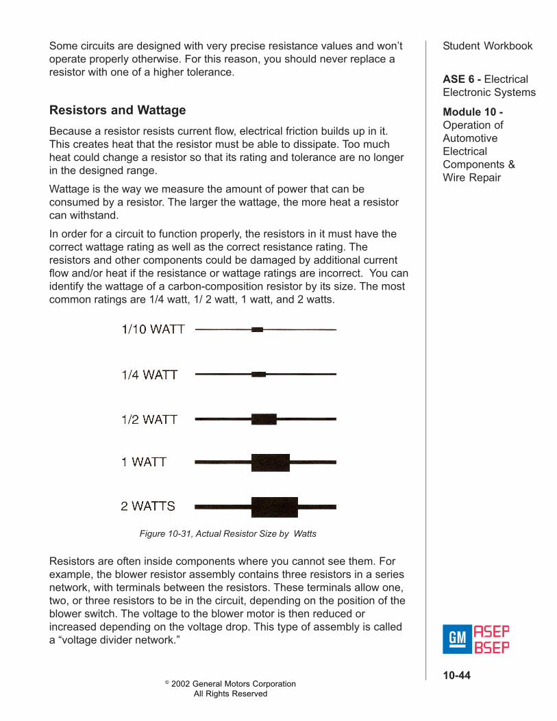
Resistors and WattageBecause a resistor resists current flow, electrical friction builds up in it.This creates heat that the resistor must be able to dissipate. Too muchheat could change a resistor so that its rating and tolerance are no longerin the designed range.Wattage is the way we measure the amount of power that can beconsumed by a resistor. The larger the wattage, the more heat a resistorcan withstand.In order for a circuit to function properly, the resistors in it must have thecorrect wattage rating as well as the correct resistance rating. Theresistors and other components could be damaged by additional currentflow and/or heat if the resistance or wattage ratings are incorrect. You canidentify the wattage of a carbon-composition resistor by its size. The mostcommon ratings are 1/4 watt, 1/ 2 watt, 1 watt, and 2 watts.
Resistors are often inside components where you cannot see them. Forexample, the blower resistor assembly contains three resistors in a seriesnetwork, with terminals between the resistors. These terminals allow one,two, or three resistors to be in the circuit, depending on the position of theblower switch. The voltage to the blower motor is then reduced orincreased depending on the voltage drop. This type of assembly is calleda “voltage divider network.”
Figure 10-31, Actual Resistor Size by Watts

© 2002 General Motors CorporationAll Rights Reserved
ASE 6 - ElectricalElectronic Systems
Module 10 -Operation ofAutomotiveElectricalComponents &Wire Repair
10-45
Student Workbook
Resistors are also used in the Steering Wheel Control system, in anassembly referred to as a resistor ladder. In this system, a button press onone of the steering wheel controls changes the resistance to currentflowing through the circuit to either the entertainment system control or theenvironmental system control. The head units then interpret the voltagelevel as a command.
Figure 10-32, Blower Resistor and Switch Schematic
Figure 10-33, Steering Wheel Control Resistor Ladder Network

© 2002 General Motors CorporationAll Rights Reserved
ASE 6 - ElectricalElectronic Systems
Module 10 -Operation ofAutomotiveElectricalComponents &Wire Repair
10-46
Student WorkbookVariable ResistorsThe kinds of resistors we have discussed so far are fixed. This meanstheir rating cannot be adjusted. Other resistors are variable. This meansthat their resistance can be changed by adjusting a control. The controlmoves a contact over the surface of a resistance. As current flows througha greater length of resistor material, the current decreases; as it flowsthrough less resistor material, current increases.The amount of variance and the number of resistance positions dependon how the variable resistor is con-structed. Some have only two differentresistance values, while others have an infinite range between their mini-mum and maximum values.Variable resistors can be linear or non-linear. The resistance of a linearresistor increases evenly. When the control is set at one fourth of itstravel, resistance increases to one fourth of the maximum; when thecontrol is set to half of its travel, resistance increases to half of itsmaximum.Variable resistors may be combined with an ON/OFF switch, such as theswitch used to control pulse wipers. The fuel tank sending unit is anexample of a simple variable resistor.
RheostatsRheostats are variable resistors that have two terminals connected inseries with the circuit. They are used to control current flow. Thewindshield wiper delay switch is an example of a rheostat.
Figure 10-34, Schematic Symbol for a Rheostat, and Wiper Delay Switch

© 2002 General Motors CorporationAll Rights Reserved
ASE 6 - ElectricalElectronic Systems
Module 10 -Operation ofAutomotiveElectricalComponents &Wire Repair
10-47
Student WorkbookPotentiometersA potentiometer - also called a pot - has three terminals and works bydividing the voltage between two of them.Potentiometers can be designed to work as rheostats.Potentiometers are often used in dimmer switches that control lightsthrough a solid state control module. The throttle position sensor (TPS) isalso a potentiometer.
Figure 10-35, Schematic Symbol for a Potentiometer, and a TPS

© 2002 General Motors CorporationAll Rights Reserved
ASE 6 - ElectricalElectronic Systems
Module 10 -Operation ofAutomotiveElectricalComponents &Wire Repair
10-48
Student WorkbookThermistorsThermistors (thermal resistors) are a type of variable resistor that operatewithout human control. A thermistor is made of carbon. The resistance ofcarbon decreases instead of increasing at higher temperatures. Thisproperty can be useful in certain electrical circuits. We’ve already seenthermistors used as circuit protectors; another common application of athermistor is in a circuit to measure temperature, such as a coolanttemperature sensor or an ambient air sensor.
Figure 10-37, Schematic Symbol for a Ptc, and an Ambient Air Sensor
Failed ResistorsFixed resistors either work (passing the proper amount of current) or theydo not (they pass no current, or allow too much current to pass).Variable resistors, on the other hand, can exhibit a “flat spot” where themoving parts brush against one another and cause wear. This canbecome evident as lack of response through a portion of the resistor’stravel.

© 2002 General Motors CorporationAll Rights Reserved
ASE 6 - ElectricalElectronic Systems
Module 10 -Operation ofAutomotiveElectricalComponents &Wire Repair
10-49
Student WorkbookExercise 10-5Read and answer each question carefully and choose the correct answer.
1. Resistors can be used to reducea. voltageb. powerc. currentd. all of the above
2. Resistors are rated in ___________.a. sizeb. resistance (ohms)c. power handling capability (watts)d. bands
3. A resistor capable of changing its resistance is called a ___________resistor.a. multi-ohmicb. solid statec. variabled. bi-ohmic
4. A throttle position sensor is an example of what type of resistor?a. rheostatb. potentiometerc. thermistord. none of the above

© 2002 General Motors CorporationAll Rights Reserved
ASE 6 - ElectricalElectronic Systems
Module 10 -Operation ofAutomotiveElectricalComponents &Wire Repair
10-50
Student Workbook5. A coolant temperature sensor is an example of what kind of resistor?a. rheostatb. potentiometerc. thermistord. none of the above
6. An analog steering control is an example of what kind of resistor?a. rheostatb. potentiometerc. thermistord. none of the above
7. Identify the following schematic symbols and give an example of eachtype.

© 2002 General Motors CorporationAll Rights Reserved
ASE 6 - ElectricalElectronic Systems
Module 10 -Operation ofAutomotiveElectricalComponents &Wire Repair
10-51
Student Workbook
Figure 10-38

© 2002 General Motors CorporationAll Rights Reserved
ASE 6 - ElectricalElectronic Systems
Module 10 -Operation ofAutomotiveElectricalComponents &Wire Repair
10-52
Student WorkbookExperiment 10-2Experiment Objectives: Demonstrate the operation of a potentiometerBuild the circuit shown in Figure 10-38.Set up the DVM to measure the voltage drop between the two terminals ofthe LED module.
1. Turn the potentiometer knob until it is completely OFF (all the waycounter-clockwise, with the LED not lit).
2. Activate the circuit by flipping the switch.3. While watching the DVM readout, slowly turn the potentiometer knob
clockwise.
What happens to the readings?
______________________________________________________________________
Observe the LED. At what voltage reading does it begin to glow? Why?
______________________________________________________________________
______________________________________________________________________
At what voltage reading does it glow the brightest? Why?
______________________________________________________________________
______________________________________________________________________

© 2002 General Motors CorporationAll Rights Reserved
ASE 6 - ElectricalElectronic Systems
Module 10 -Operation ofAutomotiveElectricalComponents &Wire Repair
10-53
Student Workbook
Figure 10-39
© 2002 General Motors CorporationAll Rights Reserved
ASE 6 - ElectricalElectronic Systems
Module 10 -Operation ofAutomotiveElectricalComponents &Wire Repair
10-54
Student WorkbookExperiment 10-3Experiment Objective: Demonstrate how a potentiometer is used as asensor.In Experiment 2-1, the potentiometer was used to control the current tothe LED module and thus control its intensity, but many variableresistance devices are used as sensors. In those cases, the potentiometeris used to change the voltage that is measured through the middleterminal.Replace Module C with a Fluke DVM set up to measure voltage, asshown.
1. Turn the potentiometer knob all the way counter-clockwise.2. Activate the circuit by flipping the switch.3. Slowly turn the potentiometer knob clockwise while observing the fuel
gauge.4. Slowly turn the potentiometer knob while observing the Fluke meter.
What happens to the meter reading once the potentiometer is turned allthe way clockwise?
______________________________________________________________________
What is the potentiometer simulating in this experiment?
______________________________________________________________________
What is the Fluke meter simulating in this experiment?
______________________________________________________________________
What does this experiment tell you the construction and operation ofvarious types of sending units?
______________________________________________________________________

© 2002 General Motors CorporationAll Rights Reserved
ASE 6 - ElectricalElectronic Systems
Module 10 -Operation ofAutomotiveElectricalComponents &Wire Repair
10-55
Student WorkbookCapacitorsA capacitor is a device that can store an electrical charge, thereby creatingan electrical field which can in turn store energy. The measurement of thisenergy storing ability is called “capacitance.” In automotive electricalsystems, capacitors are used to store energy, as timer circuits, and asfilters. The tachometer filter and the theatre dimming timer are bothcapacitors.Construction methods vary, but a simple capacitor can be made from twoplates of conductive material separated by an insulating material called a“dielectric.” Typical dielectric materials are air, paper, plastic and ceramic.
Capacitor Energy StorageIn some circuits, a capacitor can take the place of a battery. If a capacitoris placed in a circuit with a voltage source, current flows in the circuitbriefly while the capacitor “charges.” That is, electrons accumulate on thesurface of the plate connected to the negative terminal and move awayfrom the plate connected to the positive terminal. This continues until theelectrical charge of the capacitor and the voltage source are equal. Howfast this happens depends on several factors, including the voltageapplied and the size of the capacitor; it usually happens quickly.When the capacitor is charged to the same potential as the voltagesource, current flow stops. The capacitor can then hold its charge when itis disconnected from the voltage source. With the two plates separated bya dielectric, there is nowhere for the electrons to go. The negative plateretains its accumulated electrons, and the positive plate still has a deficitof electrons. This is how the capacitor stores energy.A charged capacitor can deliver its stored energy just as a battery would(although it is important to note that, unlike a battery, a capacitor storeselectricity, but does not create it). When used to deliver a suitable smallcurrent, a capacitor has the potential to deliver voltage to a circuit for aslong as a few weeks.
Figure 10-40, Charges Accumulate on the Plates of the Capacitor
© 2002 General Motors CorporationAll Rights Reserved
ASE 6 - ElectricalElectronic Systems
Module 10 -Operation ofAutomotiveElectricalComponents &Wire Repair
10-56
Student WorkbookUnits of MeasurementCapacitors are rated in units of measurement called “Farads” (representedby the symbol “F”). These specify how many electrons the capacitor canstore. The farad is a very large number of electrons. In the systems weuse, you’ll see capacitors rated in “micro-farads” (mF). A micro-farad isone millionth of a farad.In addition to being rated in farads, capacitors are also rated according tothe maximum voltage that they can handle. When replacing a capacitor,never use a capacitor with a lower voltage rating.Three factors combine to determine the capacitance of a given capacitor:1. The area of the conductive plates2. The distance between the conductive plates3. The material used as the dielectric
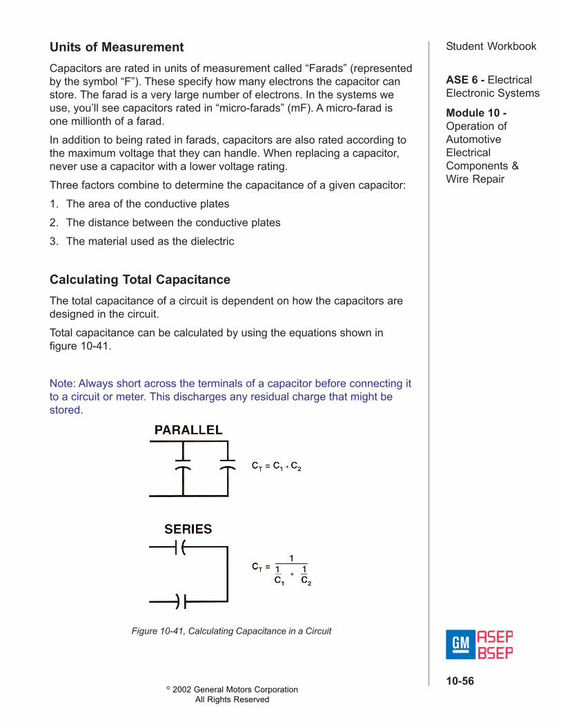
Calculating Total CapacitanceThe total capacitance of a circuit is dependent on how the capacitors aredesigned in the circuit.Total capacitance can be calculated by using the equations shown infigure 10-41.
Note: Always short across the terminals of a capacitor before connecting itto a circuit or meter. This discharges any residual charge that might bestored.
Figure 10-41, Calculating Capacitance in a Circuit

© 2002 General Motors CorporationAll Rights Reserved
ASE 6 - ElectricalElectronic Systems
Module 10 -Operation ofAutomotiveElectricalComponents &Wire Repair
10-57
Student Workbook
Figure 10-42

© 2002 General Motors CorporationAll Rights Reserved
ASE 6 - ElectricalElectronic Systems
Module 10 -Operation ofAutomotiveElectricalComponents &Wire Repair
10-58
Student WorkbookExperiment 10-4Experiment Objective: Demonstrate the effects that a capacitor has on aDC powered circuit.Assemble the circuit shown in figure 10-42. The purpose of the bulb in thecircuit is to show current flow. Record your results below.
Capacitor voltage after charging_________________________________
Capacitor voltage after discharging ______________________________
Does the bulb light? Why? _____________________________________
Does a capacitor block the flow of direct current? ___________________

© 2002 General Motors CorporationAll Rights Reserved
ASE 6 - ElectricalElectronic Systems
Module 10 -Operation ofAutomotiveElectricalComponents &Wire Repair
10-59
Student Workbook
Figure 10-43
Capacitor FilterAn important property of capacitors is their ability to pass alternatingcurrent (AC) while blocking direct current (DC). By tuning the capacitor forspecific applications, it can be used to pass desirable signals while it filtersout unwanted signals. You’ll find capacitors used in this way in audiosystems.

© 2002 General Motors CorporationAll Rights Reserved
ASE 6 - ElectricalElectronic Systems
Module 10 -Operation ofAutomotiveElectricalComponents &Wire Repair
10-60
Student WorkbookExperiment 10-5Experiment Objective: Demonstrate the effect that a capacitor has on anAC powered circuit.Connect the circuit shown in Figure 10-43 to the 12 volt power supply onyour project board.
When you apply power to the circuit which LEDs light?
BOTH________________________ONLY LED 1__________________ONLY LED 2__________________
Turn off the project board power, turn around Module M and re-connect(reversing the voltage to the module).Reapply power and check to see which LEDs lights.
BOTH_______________________ONLY LED 1__________________ONLY LED 2__________________
Does a capacitor block the flow of alternating current? ___________
Figure 10-44, Where to Add Capacitors to Control “Switch Pop”
To use these charts, first determine the type of device that is causing the“pop”; i.e. direct switch activated or relay activated. Next, add capacitorsone at a time, and then test to see if each capacitor adequately controlsthe “pop”. If the capacitor in position 1 does not control the “pop” then addthe capacitor in position 2, etc.

© 2002 General Motors CorporationAll Rights Reserved
ASE 6 - ElectricalElectronic Systems
Module 10 -Operation ofAutomotiveElectricalComponents &Wire Repair
10-61
Student Workbook
Figure 10-45
Capacitor TimerIf a charged capacitor is placed in a circuit with a resistor, current flows ina predictable way. That is, the amount of time it takes to charge anddischarge the capacitor is predictable and accurately repeatable.Because of this property, capacitors can be used to make up timercircuits.

© 2002 General Motors CorporationAll Rights Reserved
ASE 6 - ElectricalElectronic Systems
Module 10 -Operation ofAutomotiveElectricalComponents &Wire Repair
10-62
Student WorkbookExperiment 10-6Experiment Objective: Demonstrate the operation of a capacitor in atimer circuit.Assemble the circuit shown on in figure 10-45 using the 10K Ω resistor.Record your results below. Repeat the procedure several times to checkyour accuracy.
CAPACITOR VOLTAGE AFTER 60 SECONDS CHARGING __________
CAPACITOR VOLTAGE AFTER 60 SECONDS WAITING __________
TIME REQUIRED FOR LED TO GO OUT __________
CAPACITOR VOLTAGE AFTER 60 SECONDS CHARGING __________
CAPACITOR VOLTAGE AFTER 60 SECONDS WAITING __________
TIME REQUIRED FOR LED TO GO OUT __________
CAPACITOR VOLTAGE AFTER 60 SECONDS CHARGING __________
CAPACITOR VOLTAGE AFTER 60 SECONDS WAITING __________
TIME REQUIRED FOR LED TO GO OUT __________
© 2002 General Motors CorporationAll Rights Reserved
ASE 6 - ElectricalElectronic Systems
Module 10 -Operation ofAutomotiveElectricalComponents &Wire Repair
10-63
Student WorkbookAfter completing the above measurements, replace the 10K Ω resistorwith the 1,000 Ω resistor.
CAPACITOR VOLTAGE AFTER 60 SECONDS CHARGING __________
CAPACITOR VOLTAGE AFTER 60 SECONDS WAITING __________
TIME REQUIRED FOR LED TO GO OUT __________
Finally, replace the 1,000 Ω resistor with the 100 Ω resistor.
CAPACITOR VOLTAGE AFTER 60 SECONDS CHARGING __________
CAPACITOR VOLTAGE AFTER 60 SECONDS WAITING __________
TIME REQUIRED FOR LED TO GO OUT __________
What characteristics of a capacitor make it useful in a timer circuit?

© 2002 General Motors CorporationAll Rights Reserved
ASE 6 - ElectricalElectronic Systems
Module 10 -Operation ofAutomotiveElectricalComponents &Wire Repair
10-64
Student WorkbookExercise 10-6Read and answer each question carefully and answer by filling in theblanks.
1. Capacitors are commonly used as ________________and____________.a. voltage supplies, DC filtersb. resistors, DC filtersc. rheostats, potentiometersd. timers, resistors
2. A charged capacitor acts like a ___________.a. switchb. batteryc. terminald. resistor
3. The basic unit of measurement for capacitor ratings is the___________.a. Jouleb. Ohmc. Faradd. Cochrane
4. A battery ___________ electricity while a capacitor only____________electricity.a. stores, createsb. creates, storesc. distributes, collectsd. collects, distributes
5. Capacitors block the flow of ___________ current but allow___________ current to pass.a. strong, weakb. weak, strongc. AC, DCd. DC, AC