ASCO Solenoid Valves - Hazardous Area ATEX Certified Valves - New Catalogue
16
Hazardous Location Solutions | for the Process Control Industry UL • CSA • FM • ATEX • IECEx • NEPSI • INMETRO • TR CU 4 www.ascovalve.com
-
Upload
thorne-derrick -
Category
Technology
-
view
2.836 -
download
50
Transcript of ASCO Solenoid Valves - Hazardous Area ATEX Certified Valves - New Catalogue

Hazardous Location Solutions | for the Process Control IndustryUL • CSA • FM • ATEX • IECEx • NEPSI • INMETRO • TR CU
4
w w w . a s c o v a l v e . c o m
Jack Nottidge
T&D.com Stamp
Jack Nottidge
T&D.com Stamp

Global ApprovalsFluid automation equipment must operate flawlessly in haz-
ardous or explosive environments. Solenoid-operated valves
are essential components in these challenging applications.
They must comply with the strictest safety regulations while
staying up and running, cycle after cycle, year after year.
ASCO offers the world’s most comprehensive family of prod-
ucts that hold approvals from the leading global agencies —
UL, CSA, FM, ATEX, and IECEx. In addition, our valves are
inspected and certified to NEPSI in China, INMETRO in
Brazil, and TR CU in Russia. That means users can specify
highly reliable ASCO valves in their designs and be assured
they are approved for use in dangerous conditions — anywhere
in the world.
ASCO‘s global solutions for hazardous locationsinclude valves available in the following models: • Standard 3-way and 4-way solenoid valves
• Direct-acting and pilot-operated solenoid valves
• Manual reset and NAMUR valves
• Rugged 316L Stainless Steel valves for harsh environments
• Low Power Intrinsically Safe and Non-Incendive Field Wiring solenoid valves
• Low temperature constructions down to -58˚F (-50˚C)
ASCO offers hundreds of valve constructions with various global
approvals that can be exported worldwide. Our products are
famous for their robust operator heads and extended service lives.
These products are ideal for the mission-critical demands of
power generation, chemical processing, oil, gas, and refining
applications, plus general machinery, wellhead control, mining
equipment and measuring and controlling devices.
With more than 100 specialists and over 140 distributors in the
U.S. alone, ASCO has the technical expertise that can rapidly
solve application problems and help interpret confusing product
codes and classifications. Our one-stop shopping offers time-
saving convenience and rapid fulfillment. There’s only one
source to specify; one contact number to call; one solution to
keep in inventory.
Only ASCO solenoid valves deliver the advanced designs,
top-grade materials, meticulous manufacturing, and unequaled
quality assurance that maximize durability and achieve unsur-
passed performance in hazardous and explosive environments.
If you cannot find the product you need or if youneed more detailed specifications, visitwww.ascovalve.com or call 800-972-2726.
CAUTION: Users should consult www.ascovalve.com or Catalog 35 to see complete specifications for the products selected from this catalog.
WARNING: Improper selection or use of products and related items in this catalog can cause death, serious injury, or property damage.
^ # %
1
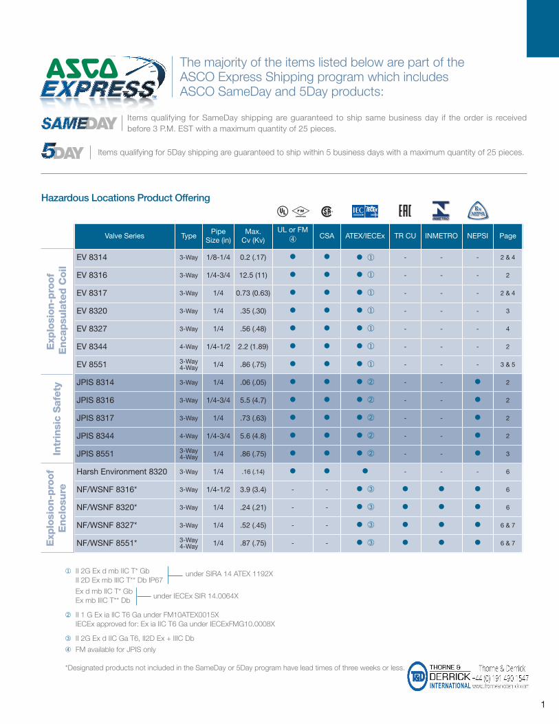
Valve Series TypePipe
Size (in)Max.Cv (Kv)
UL or FM√
CSA ATEX/IECEx TR CU INMETRO NEPSI Page
EV 8314 3-Way 1/8-1/4 0.2 (.17) • • • ¨ - - - 2 & 4
EV 8316 3-Way 1/4-3/4 12.5 (11) • • • ¨ - - - 2
EV 8317 3-Way 1/4 0.73 (0.63) • • • ¨ - - - 2 & 4
EV 8320 3-Way 1/4 .35 (.30) • • • ¨ - - - 3
EV 8327 3-Way 1/4 .56 (.48) • • • ¨ - - - 4
EV 8344 4-Way 1/4-1/2 2.2 (1.89) • • • ¨ - - - 2
EV 8551 3-Way4-Way 1/4 .86 (.75) • • • ¨ - - - 3 & 5
JPIS 8314 3-Way 1/4 .06 (.05) • • • ¡ - - • 2
JPIS 8316 3-Way 1/4-3/4 5.5 (4.7) • • • ¡ - - • 2
JPIS 8317 3-Way 1/4 .73 (.63) • • • ¡ - - • 2
JPIS 8344 4-Way 1/4-3/4 5.6 (4.8) • • • ¡ - - • 2
JPIS 8551 3-Way4-Way 1/4 .86 (.75) • • • ¡ - - • 3
Harsh Environment 8320 3-Way 1/4 .16 (.14) • • • - - - 6
NF/WSNF 8316* 3-Way 1/4-1/2 3.9 (3.4) - - • ¬ • • • 6
NF/WSNF 8320* 3-Way 1/4 .24 (.21) - - • ¬ • • • 6
NF/WSNF 8327* 3-Way 1/4 .52 (.45) - - • ¬ • • • 6 & 7
NF/WSNF 8551* 3-Way4-Way 1/4 .87 (.75) - - • ¬ • • • 6 & 7
^ # %
¨ II 2G Ex d mb IIC T* Gb
II 2D Ex mb IIIC T** Db IP67
Ex d mb IIC T* Gb
Ex mb IIIC T** Db
¡ II 1 G Ex ia IIC T6 Ga under FM10ATEX0015X
IECEx approved for: Ex ia IIC T6 Ga under IECExFMG10.0008X
¬ II 2G Ex d IIC Ga T6, II2D Ex + IIIC Db
√ FM available for JPIS only
*Designated products not included in the SameDay or 5Day program have lead times of three weeks or less.
under SIRA 14 ATEX 1192X
under IECEx SIR 14.0064X
Exp
losi
on-p
roof
Enca
psu
late
d C
oil
Intr
insi
c S
afet
yE
xplo
sion
-pro
of
Encl
osure
The majority of the items listed below are part of the ASCO Express Shipping program which includes ASCO SameDay and 5Day products:
Items qualifying for SameDay shipping are guaranteed to ship same business day if the order is received before 3 P.M. EST with a maximum quantity of 25 pieces.
Items qualifying for 5Day shipping are guaranteed to ship within 5 business days with a maximum quantity of 25 pieces.
Hazardous Locations Product Offering
Jack Nottidge
T&D.com Stamp

Hazardous Location Solutions 4
2
PipeSize(in)
OrificeSize
in (mm)
Cv FlowFactor
(Kv=m3/h)
Operating PressureDifferential psi (bar)
Max.Fluid andAmbient
Temp. °F (˚C)
Brass Body Stainless Steel BodyAir-Inert Gas
Pressure toCylinder
Cylinder toExhaust Min. Max. Catalog Number Catalog Number
Low Power (1.4 Watt)3/2 VALVES, UNIVERSAL OPERATION (Normally Closed or Normally Open) with NBR Disc – SIL 3 Capable, Certified by Exida ∆ ≥
1/4 1/16 (2) .08 (.07) .08 (.07) 0 150 (10) 140 (60) EV8314G300 EV8314G301 ≈
3/2 VALVES, NORMALLY CLOSED (Closed when de-energized) with NBR Disc – SIL 3 Capable, Certified by Exida ∆1/4 5/16 (8) 1.5 (1.29) 1.5 (1.29) ƒ 150 (10) 140 (60) EV8316G301 ¬ EV8316G381 ≈3/8 5/16 (8) 1.8 (1.37) 1.8 (1.37) ƒ 150 (10) 140 (60) EV8316G302 ¬ EV8316G382 ≈3/8 5/8 (16) 4 (3.43) 4 (3.43) ƒ 150 (10) 140 (60) EV8316G303 ¬ -
1/2 5/8 (16) 4 (3.43) 4 (3.43) ƒ 150 (10) 140 (60) EV8316G304 ¬ EV8316G384 ≈3/2 VALVES, UNIVERSAL (Normally Closed or Normally Open) "Quick Exhaust" with CR Diaphragm and NBR Disc
1/4 ¡ .08 (.07) .73 (.63) 5 (0.3) 150 (10) 140 (60) - EV8317G308 ¨≈
4/2 VALVES, Brass Body with NBR Disc
1/4 1/4 (6) .80 (0.69) 1 (0.86) 10 (0.7) 150 (10) 140 (60) EV8344G370 ¨¬ -
3/8 3/8 (10) 1.4 (1.20) 2.2 (1.89) 10 (0.7) 150 (10) 140 (60) EV8344G372 ¨¬ -
1/2 3/8 (10) 1.4 (1.20) 2.2 (1.89) 10 (0.7) 150 (10) 140 (60) EV8344G374 ¨¬ -
Intrinsically Safe3/2 VALVES, UNIVERSAL OPERATION (NORMALLY CLOSED or NORMALLY OPEN) with NBR Disc – SIL 3 Capable, Certified by Exida ∆ ≥
1/4 1/20 (1.3) .06 (.05) .06 (.05) 0 130/105 (9/7) ≈ 149 (65) JPIS8314B300 -
3/2 VALVES, NORMALLY CLOSED (Closed when de-energized) with NBR Disc or FKM (Suffix V), as Listed – SIL 3 Capable, Certified by Exida ∆1/4 5/16 (8) 1.5 (1.3) 1.5 (1.3) ƒ 130 (9) 149 (65) JPIS8316B301 ¬ -
3/8 5/16 (8) 1.8 (1.6) 1.8 (1.6) ƒ 130 (9) 149 (65) JPIS8316B302 ¬ -
3/8 5/8 (16) 4 (3.5) 4 (3.5) ƒ 130 (9) 149 (65) JPIS8316B303 ¬ -
1/2 5/8 (16) 4 (3.5) 4 (3.5) ƒ 130 (9) 149 (65) JPIS8316B304 ¬ -
3/4 11/16 (17) 5.5 (4.7) 5.5 (4.7) 10 (0.7) 130 (9) 149 (65) JPIS8316B374 ¬ -
3/2 VALVES, UNIVERSAL (NORMALLY CLOSED or NORMALLY OPEN) "Quick Exhaust" with NBR Diaphragm and NBR Disc
1/4 ¡ .06 (.07) .73 (.63) 5 (0.3) 130 (9) 149 (65) JPIS8317B307 ¨ -
4/2 VALVES, Brass Body with NBR Disc
1/4 1/4 (6) .80 (.69) 1 (.86) 10 (0.7) 130 (9) 149 (65) JPIS8344B370 ¨¬ -
3/8 3/8 (10) 1.5 (1.3) 2.2 (1.9) 10 (0.7) 130 (9) 149 (65) JPIS8344B372 ¨¬ -
1/2 3/8 (10) 1.5 (1.3) 2.2 (1.9) 10 (0.7) 130 (9) 149 (65) JPIS8344B374 ¨¬ -
3/4 3/4 (19) 5.2 (4.5) 5.6 (4.8) 10 (0.7) 130 (9) 149 (65) JPIS8344B376 ¨¬ -
¨ There are two exhaust flows in the exhaust mode (pilot and main). The pilot exhaust must be connected to the main exhaust when the air or inert gas cannot be exhausted to atmosphere.¡ For "Quick Exhaust" valves, pressure port is 1/16", exhaust port is 1/4".¬ IMPORTANT: A Minimum Operating Pressure Differential must be maintained between the pressure and exhaust ports. Supply and exhaust piping must be full area, unrestricted. ASCO flow controls and other similar components must be installed in the cylinder lines only.
ƒ Zero minimum when valve selection gasket is in external position and proper auxiliary air pressure is applied. Minimum 15 psi (1 bar) Operating Pressure Differential when selection gasket is in the internal position.
≈ Can be used for drynatural gas service with EV prefix.∆ Safety manual and FMEDA (Failure Modes Effects and Diagnostic Analysis) report available.≥ SIL 3 Capable, Certified by Exida only valid when used as Normally Closed.
Low Power & Intrinsically SafeLow Power• Molded one-piece solenoid with highly efficient solenoid cartridge and special low wattage coil• Designed for use in automation of plant control systems to provide PLC compatibility and reduced battery drainIntrinsically Safe• Designed solely for installation in intrinsically safe or Non-Incendive Field Wiring (NIFW) areas, with properly approved and sized limiting barriers
• Compatible with supervisory current applications
^ # %
Jack Nottidge
T&D.com Stamp

Hazardous Location Solutions4
3
BodyMaterial
PipeSize (in)
OrificeSize
in (mm)
Cv FlowFactor
(Kv=m3/h)
Single Solenoid – SIL 3 Capable, Certified by Exida ∆
Operating Pressure Differential psi (bar)
Max. FluidTemp. ˚F (˚C)
CatalogNumber
Air-Inert Gas
Min. Max.
Low power - Spool Valves (1.4 Watt)
3/2, 5/2 VALVES, with NBR and PUR Seals, NAMUR Mount
Aluminum 3/2, 5/2 1/4 1/4 (6) .86 (.7) 30 (2) 150 (10) 140 (60) EV8551G301 ¨
316L Stainless Steel 3/2, 5/2 1/4 1/4 (6) .86 (.7) 30 (2) 150 (10) 140 (60) EV8551G309 ¬≈
Intrinsically Safe - Spool Valves
3/2, 5/2 VALVES, with NBR and PUR Seals, NAMUR Mount
Aluminum 3/2, 5/2 1/4 1/4 (6) .86 (.74) 35 (2.4) 130 (9) 149 (65) JPIS8551B301 ¨
316L Stainless Steel 3/2, 5/2 1/4 1/4 (6) .86 (.74) 35 (2.4) 130 (9) 149 (65) JPIS8551B309
¨ 1/8" NPT exhaust for 1/4" aluminum and brass.¬ Stainless steel construction supplied standard with EV solenoid.≈ Can be used for drynatural gas service with EV prefix.∆ Safety manual and FMEDA (Failure Modes Effects and Diagnostic Analysis) report available.
Low Power & Intrinsically Safe
PipeSize(in)
OrificeSize (in)
Cv FlowFactor
(Kv=m3/h)
Operating PressureDifferential psi (bar) Max. Fluid
Temp. ˚F (˚C)
Brass Body Stainless Steel BodyWatt Rating/Class of CoilInsulation Max. AC Max. DC
Catalog Number Catalog NumberAir-InertGas
Waterƒ
Lt. Oil@ 300SSU
Air-InertGas
Waterƒ
Lt. Oil@ 300SSU AC DC AC DC
3-Way EV 8320 SeriesUNIVERSAL OPERATION (Pressure at any port)
1/4 1/16 (1.6) 0.09 (0.08) 125 (9) 130 (9) 130 (9) 75 (5) 75 (5) 75 (5) 200(93) 150 (66) EV8320G172 - 10.1/F 11.6/F
1/4 3/32 (2) 0.12 (0.10) 100 (7) 100 (7) 100 (7) 60 (4) 60 (4) 60 (4) 200(93) 150 (66) EV8320G174 EV8320G200 ¬√ 17.1/F 11.6/F
1/4 1/8 (3.2) 0.25 (0.21) 50 (3) 50 (3) 50 (3) 25 (2) 25 (2) 25 (2) 200(93) 150 (66) EV8320G176 - 17.1/F 11.6/F
1/4 11/64 (4.4) 0.35 (0.30) 20 (1) 20 (1) 20 (1) 12 (1) 12 (1) 12 (1) 200(93) 150 (66) EV8320G178 - 10.1/F 11.6/F
NORMALLY CLOSED (Closed when de-energized) – PFDAVG = 6.81 x 10⁻⁴
1/4 1/16 (1.6) 0.09 (0.08) 210 (14) 225 (15) 225 (15) 160 (11) 160 (11) 160 (11) 200(93) 150 (66) EV8320G182 - 17.1/F 11.6/F
1/4 3/32 (2) 0.12 (0.10) 150 (10) 150 (10) 150 (10) 115 (8) 115 (8) 115 (8) 200(93) 150 (66) EV8320G184 EV8320G202 ¬√ 10.1/F 11.6/F
1/4 1/8 (3.2) 0.25 (0.21) 85 (6) 85 (6) 85 (6) 60 (4) 60 (4) 60 (4) 200(93) 150 (66) - EV8320G203 ¬√ 10.1/F 11.6/F
NORMALLY OPEN (Open when de-energized)
1/4 1/16 (1.6) 0.09 (0.08) 235 (16) 250 (17) 250 (17) 160 (11) 160 (11) 160 (11) 200(93) 150 (66) EV8320G192 - 17.1/F 11.6/F
1/4 3/32 (2) 0.12 (0.10) 150 (10) 140 (10) 140 (10) 100 (7) 100 (7) 100 (7) 200(93) 150 (66) EV8320G194 - 10.1/F 11.6/F
1/4 1/8 (3.2) 0.25 (0.21) 70 (5) 70 (5) 70 (5) 55 (4) 55 (4) 55 (4) 200(93) 150 (66) EV8320G196 - 10.1/F 11.6/F
¬ Can be used for drynatural gas service with the EV prefix.√ Constructions standard rated -40˚F (-40˚C) ambient temperature. EVX prefix and TPL # not required.ƒ Water rating, CSA certified up to 232 psi (16 bar).
3-Way | General Service8320 Series
• All NPT connections are in the valve body to allow in-line piping• No Minimum Operating Pressure Differential required
^ # %
^ # %
Jack Nottidge
T&D.com Stamp

Hazardous Location Solutions 4
4
PipeSize(in)
OrificeSize
in (mm)
Cv FlowFactor
(Kv=m3/h)
Operating Pressure Differential psi (bar)Max. FluidTemp.˚F (˚C)
Brass BodyStainless Steel
Body Watt Rating/Class of CoilInsulation ¬Max. AC Max. DC
CatalogNumber
CatalogNumberPress. Exh. Press. Exh. Min. ¨
Air-InertGas Water
Lt. Oil ¨@45 SSU
Air-InertGas Water
Lt. Oil ¨@45 SSU AC DC AC DC
3-Way EV 8317 Series
NORMALLY CLOSED (Closed when de-energized)
1/4 3/32 (2) 1/4 (6) .20 (.17) .73( .63) 5 (.3) ≠ 150 (10) 150 (10) 95 (7) 75 (5) 55 (4) 30 (2) 180 (82) 104 (40) EV8317G035 EV8317G036 10.1/F 11.6/F
¨ Rating for 8321 valves established with 300 SSU light oil. ≠ Minimum Operating Pressure Differential on light oil is 10 psi (0.7 bar).
PipeSize(in)
OrificeSize
in (mm)
Cv FlowFactor
(Kv=m3/h)2-1
Cv FlowFactor
(Kv=m3/h)1-3
Operating Pressure Differential psi (bar)Max. Fluid
Temp.˚F (˚C) ¨
Brass Body Stainless Steel Body Watt Rating/Class of Coil InsulationMax. AC Max. DC
CatalogNumber
CatalogNumber
Air-InertGas
Water¡
Light Oil@ 45 SSU
Air-InertGas
Water¡
Light Oil@ 45 SSU AC DC AC DC
3-Way EV 8314 Series
UNIVERSAL OPERATION (Pressure at any port)
1/8 3/64 (1.2) 0.05 (0.04) 0.06 (0.05) 200 (14) 200 (14) 200 (14) 200 (14) 200 (14) 200 (14) 200 (93) 200 (93) EV8314H041 - 10.1/F 11.6/F
1/4 3/64 (1.2) 0.05 (0.04) 0.06 (0.05) 200 (14) 200 (14) 200 (14) 200 (14) 200 (14) 200 (14) 200 (93) 200 (93) EV8314H006 - 10.1/F 11.6/F
NORMALLY CLOSED (Closed when de-energized) – PFDAVG = 4.77 x 10⁻⁴
1/4 3/32 (2.4) 0.15 (0.13) 0.20 (0.17) 205 (14) 205 (14) 190 (13) 150 (10) 120 (8) 90 (6) 200 (93) 200 (93) EV8314H035 EV8314H121 10.1/F 11.6/F
¨ Maximum fluid temperature for light oil @ 45 SSU is 180˚F (82˚C). ¡ Water rating, CSA certified up to 232 psi (16 bar).
PipeSize(in)
OrificeSize
in (mm)
Cv FlowFactor
(Kv=m3/h)Maximum Operating
Pressure Differential psi (bar) Max. FluidTemp.˚F(˚C)
Brass Body316 StainlessSteel Body
Const.Ref.
Watt Rating/Class of CoilInsulation
Ports 1-2
Ports2-3 Air-Inert Gas Water
Light Oil @ 300 SSU Catalog Number Catalog Number AC DC
3-Way EV 8327 Series
UNIVERSAL OPERATION (Pressure at any port)
1/4 1/4 (6) .49 (.42) .56 (.48) 150 (10) 150 (10) 150 (10) 176 (80) EV8327G041 – 1 12.0/F 11.6/F
1/4 1/4 (6) .49 (.42) .56 (.48) 150 (10) 150 (10) 150 (10) 248 (120) – EV8327G042 1 12.0/F 11.6/F
3-Way | General Service
8317 Series
• Designed for quick exhaust to 0 psi through the exhaust orifice• Resilient seated poppets for tight shutoff
8314 Series
• No minimum operating pressure required • Simplest valve for basic 3-way piloting operation, only one spring and two moving parts
8327 Series
• Designed for high flow piloting with no minimum operating pressure required• Balanced poppet construction for high flow at minimum power levels
^ # %
Jack Nottidge
T&D.com Stamp
Hazardous Location Solutions4
5
BodyMaterial
PipeSize(in)
OrificeSize
in (mm)
Cv FlowFactor
(Kv=m3/h)
Single Solenoid – SIL 3 Capable, Certified by Exida ¨Watt Rating/Class of Coil Insulation
Operating Pressure Differential psi (bar) Max. FluidTemp.˚F (˚C)
CatalogNumber
Air-Inert Gas
Min. Max. AC Max. DC AC DC AC DC
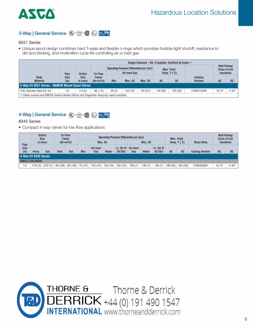
3-Way EV 8551 Series - NAMUR Mount Spool Valves316L Stainless Steel 3/2, 5/2 1/4 1/4 (6) .86 (.75) 30 (2) 150 (10) 120 (8.2) 140 (60) 120 (48) EV8551G409 10.1/F 11.6/F
¨ Safety manual and FMEDA (Failure Modes Effects and Diagnostic Analysis) report available.
PipeSize(in)
OrificeSize
in (mm)
Cv FlowFactor
(Kv=m3/h)
Operating Pressure Differential psi (bar) Max. FluidTemp.˚F (˚C) Brass Body
Watt Rating/Class of Coil InsulationMax. AC Max. DC
Press. Exh. Inlet Exh. Min.Air-InertGas Water
Lt. Oil @50 SSU
Air-InertGas Water
Lt. Oil @50 SSU AC DC Catalog Number AC DC
4-Way EV 8345 SeriesSINGLE SOLENOID1/4 1/16 (2) 3/32 (2) .09 (.08) .09 (.08) 10 (.07) 150 (10) 150 (10) 150 (10) 100 (7) 100 (7) 100 (7) 180 (82) 104 (40) EV8345G001 10.1/F 11.6/F
4-Way | General Service
3-Way | General Service
8551 Series
• Unique spool design combines hard T-seals and flexible o-rings which provides bubble-tight shutoff, resistance to dirt and sticking, and multimillion cycle life controlling air or inert gas
8345 Series
• Compact 4-way valves for low flow applications
^ # %
^ # %
Jack Nottidge
T&D.com Stamp
Hazardous Location Solutions 4
6
PipeSize
in (mm)
OrificeSize
in (mm)
Cv FlowFactor
(Kv=m3/h)
Operating Pressure Differential psi (bar)
Ambient Temp. °F (°C)
Brass Stainless
Watt Rating/Class of
Coil Insulation
Min.
Max. AC Max. DC
Air-Inert Gas Water
Light Oil@ 300SSU
Air-InertGas Water
Light Oil@ 300SSU Min Max. AC Max. DC AC DC
3/2 VALVES, UNIVERSAL, DIRECT ACTING, BALANCED POPPET
1/4 0.22 (5.7) 0.52 (0.45) 0 (0) 145 (10) 145 (10) - 145 (10) 145 (10) - -4 (-20) 248 (120) 248 (120) NF8327B101 ¨ WSNF8327B102 3.7 3.6
1/4 0.22 (5.7) 0.52 (0.45) 0 (0) 145 (10) 145 (10) - 145 (10) 145 (10) - -58 (-50) 140 (60) 140 (60) NF8327B111 ¬ WSNF8327B112 3.7 3.6
¨ Fluoroelastomer sealings and poppets. ¬ Fluorosilicone sealings and poppets.
3/2 VALVES, DIRECT ACTING, UNIVERSAL
1/4 0.13 (3.2) 0.24 (0.21) 0 (0) 49 (3.4) 49 (3.4) 50 (3.4) 25 (1.7) 25 (1.7) 25 (1.4) 32 (0) 126 (52) 104 (40) NF8320B176 WSNF8320A201 17.1 11.6
1/4 0.09 (2.4) 0.12 (0.1) 0 (0) 102 (7) 102 (7) - 58 (4) 58 (4) - -4 (-20) 194 (90) 194 (90) NF8320B174 WSNF8320A200 16.7 11.2
3/2 VALVES, DIRECT ACTING, NORMALLY CLOSED
1/4 0.09 (2.4) 0.12 (0.1) 0 (0) 145 (10) 145 (10) - 116 (8) 116 (8) - -4 (-20) 194 (90) 194 (90) NF8320A184 WSNF8320A202 10.5 11.2
3/2 VALVES, DIRECT ACTING, NORMALLY OPEN
1/4 0.09 (2.4) 0.12 (0.1) 0 (0) 73 (5) 73 (5) - 58 (4) 58 (4) - -4 (-20) 194 (90) 194 (90) NF8320A196 WSNF8320A205 10.5 11.2
1/4 0.09 (2.4) 0.12 (0.1) 0 (0) 145 (10) 145 (10) - 102 (7) 102 (7) - -4 (-20) 194 (90) 194 (90) NF8320A194 WSNF8320A204 10.5 11.2
3/2 VALVES, ZERO MINIMUM, NORMALLY CLOSED
1/4 0.31 (8) 1.5 (1.3) 0 (0) √ 145 (10) - - 116 (8) - - -4 (-20) 176 (80) 176 (80) NF8316A001 ƒ WSNF8316A081V ≈ 10.5 11.2
1/4 0.31 (8) 1.5 (1.3) 0 (0) √ 145 (10) - - 145 (10) - - -4 (-20) 140 (60) 140 (60) NF8316A301 ƒ WSNF8316A381V ≈ 1.8 1.8
3/8 0.31 (8) 1.7 (1.5) 0 (0) √ 145 (10) - - 116 (8) - - -4 (-20) 176 (80) 176 (80) NF8316A002 ƒ WSNF8316A082V ≈ 10.5 11.2
3/8 0.31 (8) 1.7 (1.5) 0 (0) √ 145 (10) - - 145 (10) - - -4 (-20) 140 (60) 140 (60) NF8316A302 ƒ WSNF8316A382V ≈ 1.8 1.8
3/8 0.63 (16) 3.9 (3.4) 0 (0) √ 145 (10) - - 116 (8) - - -4 (-20) 176 (80) 176 (80) NF8316A003 ƒ - 10.5 11.2
3/8 0.63 (16) 3.9 (3.4) 0 (0) √ 145 (10) - - 145 (10) - - -4 (-20) 140 (60) 140 (60) NF8316A303 ƒ - 1.8 1.8
1/2 0.63 (16) 3.9 (3.4) 0 (0) √ 145 (10) - - 116 (8) - - -4 (-20) 176 (80) 176 (80) NF8316A004 ƒ WSNF8316A084V ≈ 10.5 11.2
1/2 0.63 (16) 3.9 (3.4) 0 (0) √ 145 (10) - - 145 (10) - - -4 (-20) 140 (60) 140 (60) NF8316A304 ƒ WSNF8316A384V ≈ 1.8 1.8
√ Zero minimum when valve selection gasket is in external position and proper auxiliary air pressure is applied. Minimum 15 psi (1 bar) operating pressure differential when selection gasket is in the internal position. ƒ Nitrile seal materials. ≈ Fluoroelastomer seal materials.
3/2 VALVES, PILOT OPERATED, SPOOL TYPE, NORMALLY CLOSED
1/4 0.24 (6) 0.87 (0.75) 30 (2) 145 (10) - - 145 (10) - - -13 (-25) 140 (60) 140 (60) NF8551B405 ≤ 10.5 11.2
1/4 0.24 (6) 0.87 (0.75) 30 (2) 145 (10) - - 145 (10) - - -40 (-40) 176 (80) 176 (80) - WSNF8551A413 10.5 11.2
≤ Aluminum body
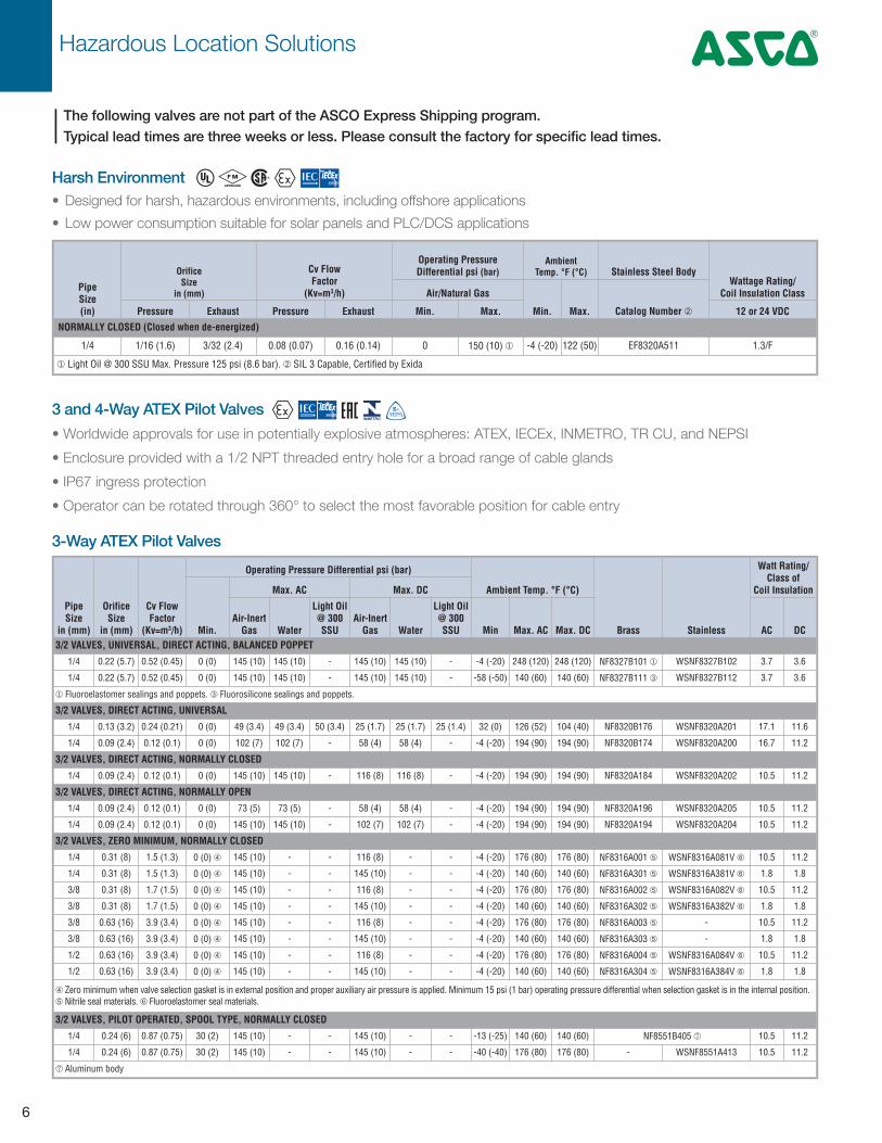
3 and 4-Way ATEX Pilot Valves
The following valves are not part of the ASCO Express Shipping program. Typical lead times are three weeks or less. Please consult the factory for specific lead times.
• Worldwide approvals for use in potentially explosive atmospheres: ATEX, IECEx, INMETRO, TR CU, and NEPSI
• Enclosure provided with a 1/2 NPT threaded entry hole for a broad range of cable glands
• IP67 ingress protection
• Operator can be rotated through 360° to select the most favorable position for cable entry
3-Way ATEX Pilot Valves
PipeSize(in)
OrificeSize
in (mm)
Cv FlowFactor
(Kv=m3/h)
Operating Pressure Differential psi (bar)
AmbientTemp. °F (°C) Stainless Steel Body
Wattage Rating/Coil Insulation ClassAir/Natural Gas
Min. Max. Catalog Number ¡Pressure Exhaust Pressure Exhaust Min. Max. 12 or 24 VDC
NORMALLY CLOSED (Closed when de-energized)
1/4 1/16 (1.6) 3/32 (2.4) 0.08 (0.07) 0.16 (0.14) 0 150 (10) ¨ -4 (-20) 122 (50) EF8320A511 1.3/F
¨ Light Oil @ 300 SSU Max. Pressure 125 psi (8.6 bar). ¡ SIL 3 Capable, Certified by Exida
Harsh Environment• Designed for harsh, hazardous environments, including offshore applications
• Low power consumption suitable for solar panels and PLC/DCS applications
^ # %
|

Hazardous Location Solutions4
7
PipeSize
in (mm)
OrificeSize
in (mm)
Cv FlowFactor
(Kv=m3/h)
Operating Pressure Differential psi (bar)
Ambient Temp. °F (°C)
Aluminum Stainless
Watt Rating/Class of
Coil Insulation
Min.
Max. AC Max. DC
Air-Inert Gas Water
Light Oil@ 300SSU
Air-InertGas Water
Light Oil@ 300SSU Min
Max.AC
Max.DC AC DC
5/2 VALVES, PILOT OPERATED, SPOOL TYPE, SINGLE SOLENOID
1/4 0.24 (6) 0.87 (0.75) 0 (0) 145 (10) - - 145 (10) - - -13 (-25) 140 (60) 140 (60) NF8551B417 - 10.5 11.2
1/4 0.24 (6) 0.87 (0.75) 0 (0) 145 (10) - - 145 (10) - - -13 (-25) 140 (60) 140 (60) NF8551B317 - 1.9 1.9
1/4 0.24 (6) 0.87 (0.75) 0 (0) 145 (10) - - 145 (10) - - -40 (-40) 176 (80) 176 (80) - WSNF8551A421 10.5 11.2
1/4 0.24 (6) 0.87 (0.75) 0 (0) 145 (10) - - 145 (10) - - -40 (-40) 176 (80) 176 (80) - WSNF8551A321 1.9 1.9
5/2 VALVES, PILOT OPERATED, SPOOL TYPE, DUAL SOLENOID
1/4 0.24 (6) 0.87 (0.75) 0 (0) 145 (10) - - 145 (10) - - -13 (-25) 140 (60) 140 (60) NF8551B418 10.5 11.2
1/4 0.24 (6) 0.87 (0.75) 0 (0) 145 (10) - - 145 (10) - - -40 (-40) 176 (80) 176 (80) - WSNF8551A422 10.5 11.2
1/4 0.24 (6) 0.87 (0.75) 0 (0) 145 (10) - - 145 (10) - - -40 (-40) 140 (60) 140 (60) - WSNF8551A322 1.9 1.9
5/2 VALVES, PILOT OPERATED, SPOOL TYPE, SINGLE SOLENOID, NAMUR
1/4 0.24 (6) 0.87 (0.75) 0 (0) 145 (10) - - 145 (10) - - -13 (-25) 140 (60) 140 (60) NF8551B401 - 10.5 11.2
1/4 0.24 (6) 0.7 (0.6) 0 (0) 145 (10) - - 145 (10) - - -40 (-40) 176 (80) 176 (80) - WSNF8551A409 10.5 11.2
1/4 0.24 (6) 0.7 (0.6) 0 (0) 145 (10) - - 145 (10) - - -40 (-40) 176 (80) 176 (80) - WSNF8551A309 1.9 1.9
PipeSize
in (mm)
OrificeSize
in (mm)
Cv FlowFactor
(Kv=m3/h)
Operating Pressure Differential psi (bar)Ambient
Temp. °F (°C)
Brass Stainless
Watt Rating/Class of
Coil Insulation
Min.
Max. AC Max. DC
Air-Inert Gas Water
Light Oil@ 300SSU
Air-InertGas Water
Light Oil@ 300SSU Min
Max.AC
Max.DC AC DC
3/2 VALVES, MANUAL RESET, NO VOLTAGE RELEASE
1/4 0.22 (5.7) 0.52 (0.45) 0 (0) 145 (10) 145 (10) - 145 (10) 145 (10) - -4 (-20) 248 (120) 248 (120) NF8327B121 WSNF8327B122 3.7 3.6
1/4 0.22 (5.7) 0.52 (0.45) 0 (0) 145 (10) 145 (10) - 145 (10) 145 (10) - -40 (-40) 104 (40) 104 (40) NF8327B171 WSNF8327B172 3.7 3.6
4-Way ATEX Pilot Valves
3-Way ATEX Pilot Valves | Manual Reset
EV Explosion-proof Encapsulated Coil
JPIS Intrinsically Safe
NF Aluminum Epoxy Coated
WSNF 316L Stainless Steel
Refer to Specification Section AC 120/60, 110/50,
230/50
DC 24V
EV 8316G301 24/DC
Enclosure Base Catalog Number Voltage
ATEX, IECEx
NF Aluminum Epoxy Coated
WSNF 316L Stainless Steel
Refer to Specification Section AC 230/50
DC 24V
22560 NEPSI
26350 INMETRO
18460 TR CU
WSNF X 225608327B212 24/DC
Enclosure Base Catalog Number VoltageApproval
NEPSI, INMETRO, and TR CU (ATEX, IECEx Standard)
How to Order
The following valves are not part of the ASCO Express Shipping program. Typical lead times are three weeks or less. Please consult the factory for specific lead times.|
Jack Nottidge
T&D.com Stamp

8
DEFINITION OF A LOCATION WHERE A POTENTIALLY EXPLOSIVE ATMOSPHERE MAY OCCURThe classification of an installation into distinct zones has two objectives (according to ATEX 1999/92/EC):- To define the categories of equipment used in the zones indicated, provided they are suitable for gases, vapours or mists and/or dusts.
- To classify hazardous places into zones to prevent ignition sources and be able to select the correct electrical and non-electrical
equipment accordingly. The zones are defined on the basis of the occurrence of explosive gaseous or dusty atmospheres.
GAS GROUPSGroup II: Equipment intended for use in places with an explosive gas atmosphere other than mines susceptible to firedamp.
Group I: Equipment intended for use in mines susceptible to firedamp.
Zone Category (ATEX 94/9/EC) Presence of explosive atmosphereszone 0 1 G ¨ Continuous, frequent or for long periods
Group II zone 1 2 G Intermittent in normal operation (likely)
zone 2 3 G Occasional or for short periods (never in normal operation)
Group I M1 ¨ Presence (methane, dust)
(mines) M2 Risk of presence (methane, dust)
DUST GROUPS (according to the fifth edition, IEC 60079-0, 2011 (EN 60079-0, 2012)¡)Group III: Equipment intended for use in places with an explosive dust atmosphere other than mines susceptible to firedamp.
Zone Category (ATEX 94/9/EC) Presence of explosive atmosphereszone 20 1 D ¨ Continuous, frequent or for long periods (air/cloud of combustible dust)
Group III zone 21 2 D Intermittent in normal operation
zone 22 3 D Occasional or for short periods
Equipment Group
II Industrial
Equipment Category
2 High Protection
Suitability of Use
G Gas
Mark for Explosion Proof Protection Method
d Flameproof
Gas/Dust Group
IIC Hydrogen/AcetyleneEquipment Protection Level
Gb High Protection (Gas)
Temperature Code
T3 200˚C
T4 135˚C
T5 100˚C
T6 85˚C
I I 2 G Ex IIC
Encapsulation
Gasses and Vapors, Dust
mb
Encapsulation
Gasses and Vapors, Dust
mbd T3.. .T6
Temperature Code
T200
T135
T100
T85
T85
Gb
Equipment Group
II Industrial
Equipment Category
2 High Protection
Suitability of Use
D Dust
Mark for Explosion Proof Protection By Enclosure
tb Dust
Gas/Dust Group
IIIC Conductive DustEquipment Protection Level
Db High Protection (Dust)
Temperature Code
6 Dust Tight
7 Temporary Submersion
I I 2 D Ex II ICtb IP67Db
Safety Code Explained
¨ G = gas ; D = dust ; M = mines¡ Including IEC 61241-0 (dusts)
Reference Guide

Reference Guide4
9
Typical Gas/Dust Group
Gas
Propane IIA
Ethylene IIB
Acetylene IIC
Dust
Combustible Fyings IIIA
Non-Conductive Dust IIIB
Conductive Dust IIIC
Level of Protection Against Solid Objects,Materials or Dust
Level of Protection Against Waterand Other Liquids
0 No protection 0 No protection
1 Protected against solid objects down to 50 mm 1 Protection against vertically fall- ing drops of water (e.g. conden- sation)
2 Protected against solid objects down to 12 mm 2 Protection against direct sprays of water up to 15 degrees from vertical
3 Protected against solid objects down to 2.5 mm 3 Protection against direct sprays of water up to 60 degrees from vertical
4 Protected against solid objects down to 1 mm 4 Protection against water sprayed from all directions - limited in- gress permitted
5 Protected against dust, limited ingress (no harmful deposits) 5 Protection against low pressure jets of water from all directions - limited
ingress permitted
6 Totally protected against dust 6 Protection against low pressure jets of water, limited ingress per- mitted (e.g. ship deck)
7 Protected against the effect of immersion between 6 in. / 15 cm and 3 ft / 1m
8 Protected against long periods of immersion under pressure
Gas & Dust Groups Ingress Protection (i.e. IP67)
EquipmentGroup
EquipmentCategory
EquipmentProtection Level
(EIC)Level of Protection
Hazard Zone (Flammable Material Present)
Gas Dust0 - 20
(Continuosly)1 - 2
(Intermittently)2 - 22
(Abnormally)
IM 1 Ma Very High - - Operable in Ex atmosphere
M 2 Mb High - - De-energized in Ex atmosphere
II
1Ga Very High G - 0 1 2
Da Very High - D 20 21 22
2Gb High G - - 1 2
Db High - D - 21 22
3Gc Normal G - - - 2
Dc Normal - D - - 22
Groups, Categories, & Zones (i.e. II 2 G Ex d IIC Gb T6 … T4)
Flammable /CombustableSubstance
ProtectionSymbol
ZonesDescription0 1 2
Gas
d l l Flameproof Enclosure
p l l Pressurised enclosure
q l l Powdery filling
o l l Immersion
e l l Increased safety
ia/ib/ic l l l Intrinsically safety
n l Non incendiaire
ma/mb/mc l l l Encapsulation
Dust
ia l Intrinsically safety
tD l Flameproof Enclosure
mD l l Encapsulation
Protection Methods
Jack Nottidge
T&D.com Stamp
Jack Nottidge
T&D.com Stamp
Reference Guide 4
10
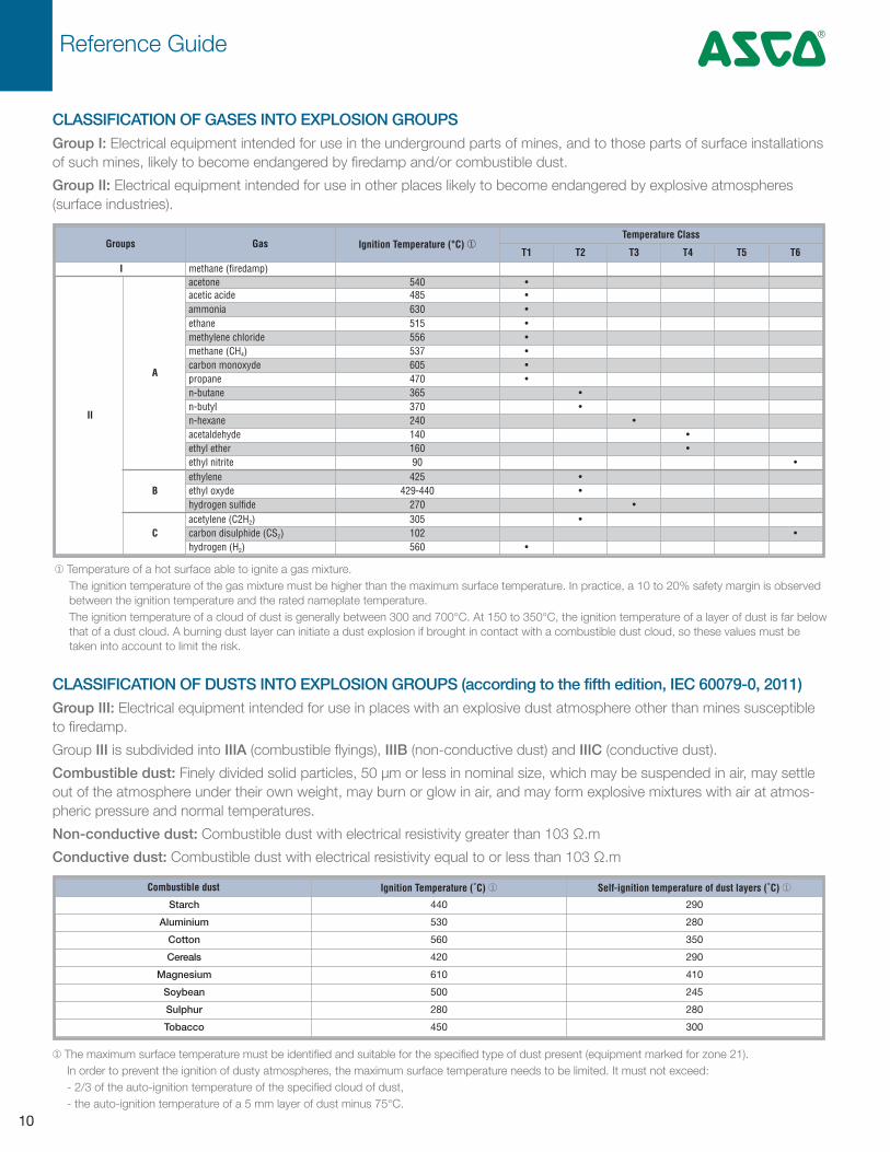
CLASSIFICATION OF GASES INTO EXPLOSION GROUPSGroup I: Electrical equipment intended for use in the underground parts of mines, and to those parts of surface installations
of such mines, likely to become endangered by firedamp and/or combustible dust.
Group II: Electrical equipment intended for use in other places likely to become endangered by explosive atmospheres
(surface industries).
¨ Temperature of a hot surface able to ignite a gas mixture.
The ignition temperature of the gas mixture must be higher than the maximum surface temperature. In practice, a 10 to 20% safety margin is observed
between the ignition temperature and the rated nameplate temperature.
The ignition temperature of a cloud of dust is generally between 300 and 700°C. At 150 to 350°C, the ignition temperature of a layer of dust is far below
that of a dust cloud. A burning dust layer can initiate a dust explosion if brought in contact with a combustible dust cloud, so these values must be
taken into account to limit the risk.
CLASSIFICATION OF DUSTS INTO EXPLOSION GROUPS (according to the fifth edition, IEC 60079-0, 2011)Group III: Electrical equipment intended for use in places with an explosive dust atmosphere other than mines susceptible
to firedamp.
Group III is subdivided into IIIA (combustible flyings), IIIB (non-conductive dust) and IIIC (conductive dust).
Combustible dust: Finely divided solid particles, 50 µm or less in nominal size, which may be suspended in air, may settle
out of the atmosphere under their own weight, may burn or glow in air, and may form explosive mixtures with air at atmos-
pheric pressure and normal temperatures.
Non-conductive dust: Combustible dust with electrical resistivity greater than 103 Ω.m
Conductive dust: Combustible dust with electrical resistivity equal to or less than 103 Ω.m
¨ The maximum surface temperature must be identified and suitable for the specified type of dust present (equipment marked for zone 21).
In order to prevent the ignition of dusty atmospheres, the maximum surface temperature needs to be limited. It must not exceed:
- 2/3 of the auto-ignition temperature of the specified cloud of dust,
- the auto-ignition temperature of a 5 mm layer of dust minus 75°C.
Groups Gas Ignition Temperature (°C) ¨Temperature Class
T1 T2 T3 T4 T5 T6
I methane (firedamp)
II
A
acetone 540 •acetic acide 485 •ammonia 630 •ethane 515 •methylene chloride 556 •methane (CH4) 537 •carbon monoxyde 605 •propane 470 •n-butane 365 •n-butyl 370 •n-hexane 240 •acetaldehyde 140 •ethyl ether 160 •ethyl nitrite 90 •
Bethylene 425 •ethyl oxyde 429-440 •hydrogen sulfide 270 •
Cacetylene (C2H2) 305 •carbon disulphide (CS2) 102 •hydrogen (H2) 560 •
Combustible dust Ignition Temperature (˚C) ¨ Self-ignition temperature of dust layers (˚C) ¨
Starch 440 290
Aluminium 530 280
Cotton 560 350
Cereals 420 290
Magnesium 610 410
Soybean 500 245
Sulphur 280 280
Tobacco 450 300

Reference Guide4
11
Valve Parts in Contact with FluidValve Series
8262 8320 8327 8316 8551 / 8553
Body 303 SS BR/303 SS BR/316 SS BR 316 SS AL/BR 316 SS
Core and Plugnut 430F SS 430F SS 430F SS 430F SS 430F SS 430F SS 430F SS
Core Tube 303 SS 303 SS 303 SS 303 SS 303 SS 303 SS 303 SS
Disc and Seals Sealings & Poppet (8327) NBR NBR FPM/VMQ/FVMQ NBR NBR NBR/PUR VMQ/PUR
Diaphragms (8316) - - - NBR FPM
Disc Holder & Core Guide - CA - - - POM POM
Springs 303 SS 303 SS 303 SS 303 SS 303 SS 303 SS 303 SS
Shading Coil SILVER Copper/Silver - Copper Silver - -
Rider Ring - - PTFE PTFE PTFE PTFE PTFE
ATEX Wetted Parts
Enclosure Type NF WSNF JPIS EV
Conduit 1/2 NPT 1/2 NPT 1/2 NPT 1/2 NPT
Solenoid Enclosure Chromated Aluminum epoxy coated 316L Stainless steel Aluminum Epoxy Encapsulated
Bonnet Steel (zinc plated) Stainless steel (nickel plated) 430F Stainless steel 416 Stainless steel
Core, Core Tube & Plugnut 430F Stainless Steel 430F Stainless steel 430F Stainless steel
Shading coil Copper or silver Not Applicable Copper or silver
Nameplate Stainless Steel 304 Stainless steel 304 Stainless steel
Electrical Connection Screw Terminals Screw Terminals Lead Wires
Fasteners and Screws Stainless steel 316 Stainless Steel Not Applicable
Materials of construction
TEMPERATURE CLASSThe temperature classification is based on the maximum surface temperature of equipment. That is the highest temperature
any part of or the entire surface of an electrical device can reach under the most unfavorable operating conditions capable
of igniting a surrounding explosive atmosphere.
Group I: Temperature ≤ 150°C or ≤ 450°C according to coal dust accumulation on equipment
Group II: Equipment must be classified and marked:
- preferably with the temperature class (T classification)
- defined by the surface temperature or, limited to the specified flammable gases or dusts for which it is approved,
if necessary (and marked accordingly).
Temperature Class Maximum Temperature (˚C) Ignition Temperature (˚C)
T1 450 > 450
T2 300 > 300
T3 200 > 200
T4 135 > 135
T5 100 > 100
T6 85 > 85
Jack Nottidge
T&D.com Stamp

Reference Guide 4
12
ProtectionSymbol
ZonesDescription Drawing
0 1 2
d
e
i
iaR L
CUib
ic
m
ma
mb
mc
n
o
p
q
Type of protection in which the parts which can ignite an explosive atmosphere are placed in an enclosure which can withstand the pressure developed during an internal explosion of an explosive mixture and which prevents the transmission of the explosion to the explosive atmospheres surrounding the enclosure.
Type of protection in which measures are applied so as to prevent with a higher degree of safety the possibility of exces-sive temperatures and of the occurrence of arcs or sparks in the interior and on the external parts of electrical apparatus, which does not produce them in normal service.
Type of protection when no spark or any thermal effect in the circuit, produced in the test conditions prescribed in the standard (which include normal operation and specific fault conditions), is capable of causing ignition.
Type of protection in which the parts which can ignite an explosive atmosphere are enclosed in a resin sufficiently resistant to the environmental influences in such a way that this explosive atmosphere cannot be ignited by either sparking or heating which may occur within the encapsulation.
Method of protection for electrical equipment designed so that it will not ignite the surrounding explosive atmosphere in normal operation and under certain fault conditions specified in the standard. There are 4 categories of equipment: nA (non-sparking), nC (enclosed break), nR (restricted breathing), nL (limited energy).
Type of protection in which the electrical apparatus is immersed in oil.
Type of protection in which the protective inert gas inside the enclosure is maintained at a higher pressure than that of the surrounding atmosphere.
Type of protection in which the enclosure is filled with a material in a finely granulated state.
TYPES OF PROTECTION FOR ELECTRICAL APPARATUS FOR USE IN GAS ATMOSPHERES.It is the comprehensive range of protective measures applied to an electrical apparatus to prevent possible ignition of the
surrounding atmosphere.
Jack Nottidge
T&D.com Stamp

Reference Guide4
13
Protectionsymbol
ZonesDescription Drawing
0 1 2
tD
mD
maD
mbD
iD
Electrical apparatus protected by enclosure and surface temperature limitation for use in areas where combustible dust may be present in quantities which could lead to a fire or explosion hazard. The ignition protection is based on the limitation of the maximum surface temperature of the enclosure and other surfaces which may come into contact with dust and on the restriction of dust ingress into the enclosure by the use of “dust-tight” or “dust-protected” enclosures. This standard is not applicable to electrical apparatus intended for use in underground parts of mines as well as those parts of surface installations of such mines endangered by firedamp and/or combustible dust; nor does it take account of any risk due to an emission of flammable or toxic gas from the dust.
Electrical apparatus protected by encapsulation type of protection ‘mD’ and surface temperature limitation for use in areas where combustible dust may be present in quantities which could lead to a fire or explosion hazard. Type of protection in which the parts which can ignite an explosive atmosphere are enclosed in a resin sufficiently resistant to environmental influences in such a way that a dust cloud or layer cannot be ignited during installation or operation.
Intrinsically safe apparatus intended for use in potentially explosive dust cloud or dust layer environments and for associated apparatus that is intended for connection to intrinsically safe circuits which enter such environments. Applicable to electrical apparatus in which the electrical circuits themselves are incapable of causing an explo-sion in the surrounding combustible dust environment.
R L
CU
TYPES OF PROTECTION FOR ELECTRICAL APPARATUS FOR USE IN THE PRESENCE OF COMBUSTIBLEDUST (EN 60241-0)Applicable to electrical apparatus for use in areas where combustible dust may be present in quantities which could lead to a
fire or explosion hazard.
EN 61241-1 = tD ; EN 61241-18 = mD ; EN 61241-11 = iD
Jack Nottidge
T&D.com Stamp

ASCO Valve, Inc. (USA) | Tel (1) 800.972.2726 | www.ascovalve.com | e-mail: [email protected] 06/15 — V7715
Global Contacts
Australia (61) 2-9-451-7077
Brazil (55) 11-4208-1700
Canada (1) 519-758-2700
China (86) 21-3395-0000
Czech Republic (420) 235-090-061
Dubai - UAE (971) 4 811 8200
France (33) 2-37-24-42-24
Germany (49) 7237-9960
India (91) 44-39197300
Italy (39) 02-356931
Japan (81) 798-65-6361
Mexico (52) 55-5809-5640
Netherlands (31) 33-277-7911
Singapore (65) 6556-1100
South Korea (82) 2-3483-1570
Spain (34) 942-87-6100
United Kingdom (44) 1695-713600
Jack Nottidge
T&D.com Stamp