ASCO 7000 Series Power Transfer Switch Technical Data and ... · ATS/NTS/MTS Only J = 150A-600A H =...
16
ASCO 7000 SERIES Power Transfer Switch Technical Data and Ordering Information
Transcript of ASCO 7000 Series Power Transfer Switch Technical Data and ... · ATS/NTS/MTS Only J = 150A-600A H =...

ASCO 7000 Series Power Transfer SwitchTechnical Data and Ordering Information

7000 SERIES ORDERING INFORMATIONTo order an ASCO 7000 SERIES Power Transfer Switch, complete the following catalog number:
Frame Transition Type Neutral CodePhasePoles
AmperesVoltage Code
GroupCode
Enclosure
D1 = 30A-230AATS/NTS/MTSOnly
J = 150A-600A
H = 800A-1200A
G = 1600A-4000A
Automatic07ATS Automatic, Open 7ACTS Automatic, Closed Transition
7ADTS Automatic, Delayed Transition
07ATB Automatic, Open Transition Bypass
7ACTB Automatic, Closed Transition Bypass
7ADTB Automatic, Delayed Transition Bypass
Non-Automatic07NTS Non Automatic, Open
07MTS Non Automatic, Open 7NCTS Non Automatic, Closed Transition 7NDTS Non Automatic Delayed Transition
7NTB Non Automatic, Open Transition Bypass
7NCTB Non Automatic, Closed Transition Bypass
7NDTB Non Automatic, Delayed Transition Bypass
0 = No Neutral A = Solid Neutral
B = Switched Neutral
C2 = Overlapping Neutral
2
3
0030
0070
0100
0150
0200
02301
0260
0400
0600
0800
1000
1200
1600
2000
2600
3000
4000
A = 115
B = 120
C = 208
D = 220
E = 230
F = 240
H = 380
J = 400
K = 415
L = 440
M = 460
N = 480
P = 550
Q = 575
R = 600
50No Optional Accessories
5XOptional
Accessories
5ZVATS
5DVATS with
Distribution Breakers
0 = Open Type (zero)
C = Type 1 Enclosure
F = Type 3R3 Enclosure
G = Type 4 Enclosure
H = Type 4X4 Enclosure
L = Type 12 Enclosure M = Type 3R3 Secure Double Door5 Enclosure N = Type 4 Secure Double Door5 Enclosure
P = Type 4X4 Secure Double Door5 Enclosure Q =Type 12 Enclosure Double Door5 Enclosure R = Type 3RX4 Secure Double Door5 Enclosure S = Type 3RX Secure Double Door5 Enclosure (316 Stainless Steel) U = Type 4X Enclosure (316 Stainless Steel) V = Type 4X Secure Double Door5 Enclosure (316 Stainless Steel)
J 07ATS A 3 0600 N 5X C
Notes: 1. 230 amp switch limited to 480 volts maximum, for D7ATS only.2. Overlapping neutral is only available on J, H & G open transition transfer switches. D-frame overlapping neutral is only available for IEC listed switches 30 to 225
amps. Overlapping switch neutral is only available on "D" frame 30-230 amp IEC listed product.3. Type 3R enclosures are not suitable for installations likely to experience windblown snow or rain conditions.4. Type 304 stainless steel is standard. To provide an improved reduction in corrosion in salt or marine environments, specify optional type 316 stainless steel.5. Double door enclosures are door over internal dead front panels/doors. All controls are mounted on internal panel/door. External door is pad-lockable for
secure applications.
A comprehensive ASCO Limited Guardian Warranty covers 7000 SERIES Power Transfer Switch(s) and warranties the product to be free of defects in material and workmanship from date of shipment. The warranty provides:
• 2 years for labor and travel expenses (extendable in 1 year increments up to 5 years for a nominal fee).• 5 years for parts (2 years for circuit breakers).• 10 years for main contacts.
Refer to Publication 3227 for warranty details, terms and conditions.
The Example Catalog Number above is J07ATSA30600N5XC2

7000 SERIES ORDERING INFORMATION — POWER CONNECTION DETAILS
Transfer Switch Configurations 7ATS, 7NTS, 7ADTS, 7ACTS, 7NDTS, 7NCTS
Transfer Switch Configurations 7ATB, 7NTB, 7ADTB, 7ACTB, 7NDTB, 7NCTB
Sizes of UL-Listed Solderless Screw-Type Terminals for External Power Connections
Sizes of UL-Listed Solderless Screw-Type Terminals for Power Connections
Notes: 1. All main terminals are rear connected
Notes: 1. 200 and 230 amp rating for copper conductors only for transfer switch configurations only.2. All main terminals are rear connected.
Switch Rating Amps Max # of Conductors per TerminalRange of AL-CU Conductor Sizes
Open Type Enclosed Type
D1 Frame 30-230A ATS & NTS Only One #14 to 4/0 AWG #14 to 4/0 AWG
J Frame 150 - 400AOne #4 AWG to 600 MCM #4 AWG to 600 MCM
Two #1/0 AWG to 600 MCM #1/0 AWG to 600 MCM
J Frame 600A Two #1/0 AWG to 600 MCM #1/0 AWG to 600 MCM
H Frame 600A Two #1/0 AWG to 600 MCM #1/0 AWG to 600 MCM
H Frame 800 - 1200A Four #1/0 AWG to 750 MCM #1/0 AWG to 600 MCM
G Frame 1000 - 1200A Four #1/0 AWG to 750 MCM #1/0 AWG to 600 MCM
G Frame 1600 - 2000A Six #1/0 AWG to 750 MCM #1/0 AWG to 600 MCM
G Frame 2600 - 4000A2 Twelve #1/0 AWG to 750 MCM #1/0 AWG to 600 MCM
Switch Rating Amps Max # of Conductors per TerminalRange of AL-CU Conductor Sizes
Open Type Enclosed Type
J Frame 150 - 400AOne #4 AWG to 600 MCM #4 AWG to 600 MCM
Two #1/0 AWG to 600 MCM #1/0 AWG to 600 MCM
J Frame 600A Two #2 AWG to 600 MCM #2 AWG to 600 MCM
H Frame (Front & Rear Connected) 600A Two #2 AWG to 600 MCM #2 AWG to 600 MCM
H Frame (Front Connected) 800 - 960A Three #1/0 AWG to 600 MCM #1/0 AWG to 600 MCM
H Frame (Rear Connected) 800 – 1200A Four #1/0 AWG to 750 MCM #1/0 AWG to 600 MCM
G Frame 1000 - 1200A1 Four #1/0 AWG to 750 MCM #1/0 AWG to 600 MCM
G Frame 1600 – 2000A1 Six #1/0 AWG to 750 MCM #1/0 AWG to 600 MCM
G Frame 2600 – 3000A1 Ten #1/0 AWG to 750 MCM #1/0 AWG to 600 MCM
G Frame 4000A1 Twelve #1/0 AWG to 750 MCM #1/0 AWG to 600 MCM
3

7000 SERIES DESIGNED TO FIT ANYWHEREAutomatic Transfer Switching – Open Transition: 7ATS, 7NTS, 7MTS (Non-Bypass)
Dimensions and Shipping Weights*
Notes: 1. Consult ASCO for dimensions on enclosures other than UL type 1. 2. Open weights include transfer switch and controller. 1200-4000 amp enclosures require ventilation openings, refer to drawing for details.3. Enclosures are free-standing with removable top, sides, and back.4. Order accessory 40MY for 1600A and 40NY for 2000A Front Connected (F/C) design.
*All dimensions and weights shown are approximate and should not be used for construction purposes. Verified dimensions can be furnished upon request.
FrameSwitch Ratings
Amp
Neutral Type & Poles
Type 1 Enclosure1 Open Switch ConfigurationWidth In
(mm) Height In
(mm)Depth In
(mm)Weightlb (kg)
Width In(mm)
Height In(mm)
Depth In(mm)
Open2
lb (kg)
D 30, 70, 100
02 or A2
18 (457) 48 (1219) 13 (330)
70 (32)
10 (260) 10 (260) 5.5 (140)
30 (14)
03 or A3 80 (36) 35 (16)
B3 85 (39) 40 (18)
D 150, 200, 230
02 or A2
18 (457) 48 (1219) 13 (330)
115 (52)
10 (260) 10 (260) 5.5 (140)
35 (16)
03 or A3 120 (55) 40 (18)
B3 130 (59) 45 (21)
J 150, 260, 400
02 or A2
24 (610) 56 (1422) 14 (356)
270 (123)
19 (470) 25 (635) 8 (203)
220 (100)
03 or A3 280 (128) 230 (105)
B3 290 (132) 240 (109)
J 600
02 or A2
24 (610) 63 (1600) 17 (432)
270 (123)
19 (470) 30 (762) 10 (251)
260 (119)
03 or A3 280 (128) 270 (123)
B3 290 (132) 280 (128)
H 600, 800, 1000
02 or A2
34 (864) 72 (1829) 20 (508)
470 (214)
27 (686) 31 (787) 13 (327)
260 (119)
03 or A3 480 (219) 270 (123)
B3 490 (223) 280 (128)
H 1200
02 or A2
38 (965) 87 (2210) 23 (584)
670 (308)
27 (686) 31 (787) 13 (327)
300 (137)
03 or A3 680 (310) 310 (141)
B3 690 (315) 320 (146)
G 1000, 16003, 20003
02 or A2
38 (965) 91 (2311) 48 (1219)
1330 (606)
33 (845) 28 (711) 26 (667)
450 (205)
03 or A3 1350 (616) 470 (214)
B3 1400 (638) 500 (228)
G1600, 2000
(Front Connected)4
02 or A2
38 (965) 87 (2210) 23(584)
1300 (590)
33 (845) 28 (711) 26 (667)
450 (205)
03 or A3 1345 (612) 470 (214)
B3 1390 (635) 500 (228)
G 26003, 30003
02 or A2
38 (965) 91 (2311) 60 (1524)
2150 (980)
33 (845) 29 (711) 31 (781)
890 (406)
03 or A3 2180 (994) 920 (420)
B3 2230 (1017) 1000 (456)
G 40003
02 or A260
(1524) 92 (2311) 72 (1829)
2250 (1026)
60 (1524) 70 (1778) 53 (1272)
990 (451)
03 or A3 2280 (1040) 1020 (465)
B3 2330 (1062) 1100 (502)
4

7000 SERIES DESIGNED TO FIT ANYWHEREAutomatic Transfer Switching – Closed and Delayed Transition: 7ACTS, 7ADTS, 7NCTS, 7NDTS
Dimensions and Shipping Weights*
Notes: 1. Consult ASCO for dimensions on enclosures other than UL type 1.2. Open weights include transfer switch and control panel. 1200-4000 amp enclosures require ventilation openings, refer to drawings for details.3. Enclosures are free-standing with removable top, sides, and back.4. Order accessory 40MY for 1600A and 40NY for 2000A front connected design.
*All dimensions and weights shown are approximate and should not be used for construction purposes. Verified dimensions can be furnished upon request
FrameSwitch Ratings
Amp
Neutral Type & Poles
Type 1 Enclosure1 Open Switch Configuration2
Width In(mm)
Height In(mm)
Depth In(mm)
Weightlb (kg)
Width In(mm)
Height In(mm)
Depth In(mm)
Weightlb (kg)
J 150, 200, 230, 260, 400
0324 (610) 56 (1422) 14 (356)
320 (146) 18.5 (470) 25 (635) 8 (203)
220 (100)
B3 330 (150) 230 (105)
J 60003
24 (610) 63 (1600) 17 (432)380 (173)
19 (483) 30 (762) 10 (251)260 (119)
B3 390 (178) 270 (123)
H 600, 800, 100003
34 (864) 72 (1829) 20 (508)480 (219)
27 (686) 31 (787) 13 (327)360 (164)
B3 490 (223) 370 (169)
H 120003
38 (965) 87 (2210) 23 (584)680 (310)
27 (686) 31 (787) 13 (327)360 (164)
B3 690 (315) 380 (173)
G 1000, 16003, 2000303
38 (965) 91 (2311) 48 (1219)1350 (616)
33 (845) 28 (711) 26 (667)580 (264)
B3 1400 (638) 600 (274)
G1600, 2000
(Front Connected)4
0338 (965) 87 (2210)
23.5
(597)
1345 (612)33 (845) 28 (711) 26 (667)
580 (264))
B3 1390 (635) 600 (274)
G 26003, 3000303
38 (965) 91 (2311) 60 (1524)2180 (994)
33 (845) 29 (711) 31 (781)1060 (483)
B3 2230 (1017) 1100 (502)
G 4000303 60
(1524) 92 (2311) 72 (1829)2290 (1044)
60 (1524) 70 (1778) 53 (1272)1060 (483)
B3 2380 (1085) 1140 (520)
5

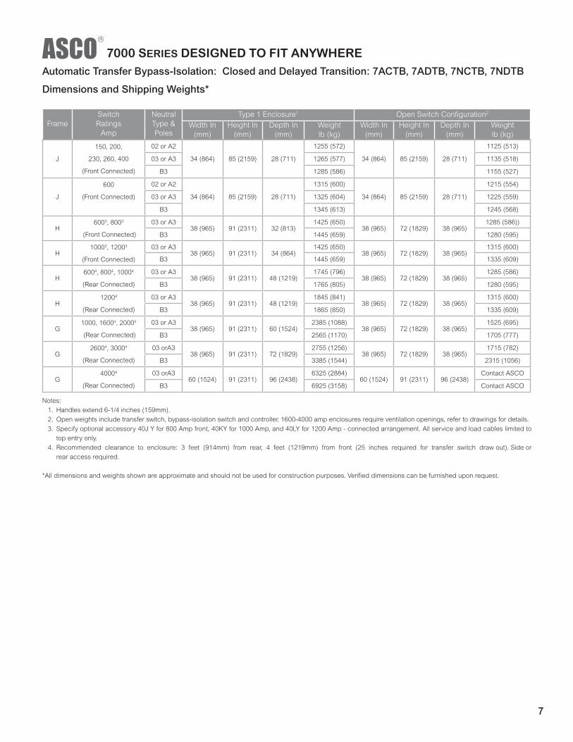
Notes: 1. Handles extend 6-1/4 inches (159mm). 2. Open weights include transfer switch, bypass-isolation switch and controller. 1600-4000 amp enclosures require ventilation openings, refer to drawings for details.3. Specify optional accessory 40J Y for 800 Amp front, 40KY for 1000 Amp, and 40LY for 1200 Amp - front connected arrangement. All service and load cables limited
to top entry only.4. Recommended clearance to enclosure: 3 feet (914mm) from rear, 4 feet (1219mm) from front (25 inches required for transfer switch draw out). Side or
rear access required.
*All dimensions and weights shown are approximate and should not be used for construction purposes. Verified dimensions can be furnished upon request.
7000 SERIES DESIGNED TO FIT ANYWHEREAutomatic Transfer Bypass-Isolation – Open Transition: 7ATB, 7NTB
Dimensions and Shipping Weights*
FrameSwitch Ratings
Amp
Neutral Type & Poles
Type 1 Enclosure1 Open Switch Configuration2
Width In(mm)
Height In(mm)
Depth In(mm)
Weightlb (kg)
Width In(mm)
Height In(mm)
Depth In(mm)
Weightlb (kg)
J
150, 200, 230,
260, 400
(Front Connected)
02 or A2
34 (864) 85 (2159) 28 (711)
1230 (561)
34 (864) 85 (2159) 28 (711)
1100 (502)
03 or A3 1240 (565) 1110 (506)
B3 1260 (575) 1130 (515)
J
600
(Front Connected)
02 or A2
34 (864) 85 (2159) 28 (711)
1290 (588)
34 (864) 85 (2159) 28 (711)
1190 (543)
03 or A3 1300 (593) 1200 (547)
B3 1320 (602) 1220 (556)
H600, 800
(Front Connected)3
03 or A338 (965) 91 (2311) 32 (813)
1400 (638)38 (965) 72 (1829) 38 (965)
1260 (575)
B3 1420 (648) 1280 (584)
H1000, 1200 (Front
Connected)3
03 or A338 (965) 91 (2311) 34 (864)
1430 (650)38 (965) 72 (1829) 38 (965)
1290 (588)
B3 1450 (659) 1310 (597)
H600, 800, 1000 (Rear
Connected)
03 or A338 (965) 91 (2311) 48 (1219)
1720 (784)38 (965) 72 (1829) 38 (965)
1260 (575)
B3 1740 (793) 1280 (584)
H1200
(Rear Connected)4
03 or A338 (965) 91 (2311) 48 (1219)
1820 (830)38 (965) 72 (1829) 38 (965)
1290 (588)
B3 1840 (839) 1310 (597)
G1000, 1600, 2000
(Front Connected)4
03 or A338 (965) 91 (2311) 60 (1524)
2360 (1076)38 (965) 72 (1829) 38 (965)
1500 (684)
B3 2540 (1158) 1680 (766)
G2600, 3000 (Rear
Connected)4
03 or A338 (965) 91 (2311) 72 (1829)
2730 (1245)38 (965) 72 (1829) 38 (965)
1690 (771)
B3 3360 (1532) 2290 (1044)
G4000
(Rear Connected)4
03 or A360 (1524) 92 (2311) 96 (2438)
6300 (2873)60 (1524) 91 (2311) 96 (2438)
Contact ASCO
B3 6900 (3146) Contact ASCO
6
Notes: 1. Handles extend 6-1/4 inches (159mm).2. Open weights include transfer switch, bypass-isolation switch and controller. 1600-4000 amp enclosures require ventilation openings, refer to drawings for details.3. Specify optional accessory 40J Y for 800 Amp front, 40KY for 1000 Amp, and 40LY for 1200 Amp - connected arrangement. All service and load cables limited to
top entry only.4. Recommended clearance to enclosure: 3 feet (914mm) from rear, 4 feet (1219mm) from front (25 inches required for transfer switch draw out). Side or
rear access required.
*All dimensions and weights shown are approximate and should not be used for construction purposes. Verified dimensions can be furnished upon request.
FrameSwitch Ratings
Amp
Neutral Type & Poles
Type 1 Enclosure1 Open Switch Configuration2
Width In(mm)
Height In(mm)
Depth In(mm)
Weightlb (kg)
Width In(mm)
Height In(mm)
Depth In(mm)
Weightlb (kg)
J
150, 200,
230, 260, 400
(Front Connected)
02 or A2
34 (864) 85 (2159) 28 (711)
1255 (572)
34 (864) 85 (2159) 28 (711)
1125 (513)
03 or A3 1265 (577) 1135 (518)
B3 1285 (586) 1155 (527)
J
600
(Front Connected)
02 or A2
34 (864) 85 (2159) 28 (711)
1315 (600)
34 (864) 85 (2159) 28 (711)
1215 (554)
03 or A3 1325 (604) 1225 (559)
B3 1345 (613) 1245 (568)
H6003, 8003
(Front Connected)
03 or A338 (965) 91 (2311) 32 (813)
1425 (650)38 (965) 72 (1829) 38 (965)
1285 (586))
B3 1445 (659) 1280 (595)
H10003, 12003
(Front Connected)
03 or A338 (965) 91 (2311) 34 (864)
1425 (650)38 (965) 72 (1829) 38 (965)
1315 (600)
B3 1445 (659) 1335 (609)
H6004, 8004, 10004
(Rear Connected)
03 or A338 (965) 91 (2311) 48 (1219)
1745 (796)38 (965) 72 (1829) 38 (965)
1285 (586)
B3 1765 (805) 1280 (595)
H12004
(Rear Connected)
03 or A338 (965) 91 (2311) 48 (1219)
1845 (841)38 (965) 72 (1829) 38 (965)
1315 (600)
B3 1865 (850) 1335 (609)
G1000, 16004, 20004
(Rear Connected)
03 or A338 (965) 91 (2311) 60 (1524)
2385 (1088)38 (965) 72 (1829) 38 (965)
1525 (695)
B3 2565 (1170) 1705 (777)
G26004, 30004
(Rear Connected)
03 orA338 (965) 91 (2311) 72 (1829)
2755 (1256)38 (965) 72 (1829) 38 (965)
1715 (782)
B3 3385 (1544) 2315 (1056)
G40004
(Rear Connected)
03 orA360 (1524) 91 (2311) 96 (2438)
6325 (2884)60 (1524) 91 (2311) 96 (2438)
Contact ASCO
B3 6925 (3158) Contact ASCO
Automatic Transfer Bypass-Isolation: Closed and Delayed Transition: 7ACTB, 7ADTB, 7NCTB, 7NDTB
Dimensions and Shipping Weights*
7000 SERIES DESIGNED TO FIT ANYWHERE
7

7000 SERIES 30 CYCLE ORDERING INFORMATIONTo order an ASCO 7000 SERIES Power Transfer Switch, complete the following catalog number:
P 07ATS A 3 0600 N 5X C
Frame Transition Type Neutral CodePhasePoles
AmperesVoltage Code
GroupCode
Enclosure
P = 600A - 800AATS/CTS/DTS
P = 600A - 1200AATB/ACTB/ADTB
Q = 600A - 1600A
S = 800A - 2000A
G = 1600A - 4000A U = 2600A - 4000A
Automatic07ATS Automatic, Open 7ACTS Automatic, Closed Transition
7ADTS Automatic, Delayed Transition
07ATB Automatic, Open Transition Bypass
7ACTB Automatic, Closed Transition Bypass
7ADTB Automatic, Delayed Transition Bypass
Non-Automatic07NTS Non Automatic, Open 7NCTS Non Automatic, Closed Transition
7NDTS Non Automatic, Delayed Transition
7NTB Non Automatic, Open Transition Bypass 7NCTB Non Automatic, Closed Transition Bypass 7NDTB Non Automatic, Delayed Transition Bypass
0 = No Neutral A = Solid Neutral
B = Switched Neutral
3 0600
0800
1000
1200
1600
2000
2600
3000
4000
A = 115
B = 120
C = 208
D = 220
E = 230
F = 240
H = 380
J = 400
K = 415
L = 440
M = 460
N = 480
P = 550
Q = 575
R = 600
50No Optional Accessories
5XOptional
Accessories
5ZVATS
5DVATS with
Distribution Breakers
0 = Open Type (zero)
C = Type 1 Enclosure M = Type 3R1 Secure Double Door3 Enclosure N = Type 4 Secure Double Door3 Enclosure
P = Type 4X2 Secure Double Door3 Enclosure Q = Type 12 Enclosure Double Door3 Enclosure R = Type 3RX1, 2 Secure Double Door4 Enclosure S = Type 3RX1 Secure Double Door3 Enclosure (316 Stainless Steel) V = Type 4X Secure Double Door3 Enclosure (316 Stainless Steel)
The Example Catalog Number above is P07ATSA30600N5XC
Notes: 1. Type 3R enclosures are not suitable for installations likely to experience windblown snow or rain conditions.2. Type 304 stainless steel is standard. To provide an improved reduction in corrosion in salt or marine environments, specify optional type 316 stainless steel.3. Double door enclosures are door over internal dead front panels/doors. All controls are mounted on internal panel/door. External door is pad-lockable for
secure applications.
A comprehensive ASCO Limited Guardian Warranty covers 7000 SERIES Power Transfer Switch(s) and warranties the product to be free of defects in material and workmanship from date of shipment. The warranty provides:
• 2 years for labor and travel expenses (extendable in 1 year increments up to 5 years for a nominal fee).• 5 years for parts (2 years for circuit breakers).• 10 years for main contacts.
Refer to Publication 3227 for warranty details, terms and conditions.
8

30 Cycle Automatic Transfer Switch (Non-Bypass) & Bypass - Isolation Switch7ATS, 7NTS, 7ACTS, 7ADTS, 7NTCS, 7NDTS, 7ATB, 7NTB, 7ACTB, 7ADTB, 7NCTB, 7NTBDimensions and Shipping Weights*
Frame Switch Ratings Amp Switch ConfigurationType 1 Enclosure1, 2
Width In(mm)
Height In(mm)
Depth In(mm)
Weightlb (kg)
P
600 - 800A (Front Connected ATS)
ATS/NTS34 (864) 72 (1829) 20 (508)
470 (214)
ACTS, ADTS, NCTS, NDTS 480 (219)
600 - 800A (Front Connected BPS)
ATB/NTB38 (965) 91 (2311) 48 (1219)
1420 (648)
ACTB, ADTB, NCTB, NDTB 1445 (659)
Q
600 - 1600A(Front Connected ATS)
ATS/NTS38 (965) 87 (2210) 23 (584)
1005 (458)
ACTS, ADTS, NCTS, NDTS 1105 (504)
600 - 1600A(Rear Connected BPS)
ATB/NTB38 (965) 91 (2311) 60 (1524)
2385 (1086)
ACTB, ADTB, NCTB, NDTB 2485 (1131)
S3
800 - 2000A(Rear Connected ATS)
ATS/NTS38 (965) 91 (2311) 60 (1524)
1645 (749)
ACTS, ADTS, NCTS, NDTS 1745 (794)
800 - 2000A(Rear Connected BPS)
ATB/NTB38 (965) 87 (2210)
23.5
(597)
2890 (1318)
ACTB, ADTB, NCTB, NDTB 2990 (1364)
G3
1600 - 2000A(Front & Rear Connected ATS)
ATS/NTS38 (965) 91 (2311) 48 (1219)
1350 (616)
ACTS, ADTS, NCTS, NDTS 1400 (638)
1600 - 2000A(Rear Connected BPS)
ATB/NTB38 (965) 91 (2311) 60 (1524)
2385 (1088)
ACTB, ADTB, NCTB, NDTB 2565 (1170)
2600 - 3000A(Rear Connected ATS)
ATS/NTS38 (965) 91 (2311) 60 (1524)
2180 (994)
ACTS, ADTS, NCTS, NDTS 2230 (1017)
2600 - 3000A(Rear Connected BPS)
ATB/NTB 60
(1524)91 (2311) 72 (1829)
2930 (1329)
ACTB, ADTB, NCTB, NDTB 3360 (1532)
4000A(Rear Connected ATS)
ATS/NTS 60
(1524)91 (2311) 72 (1829)
2290 (1044)
ACTS, ADTS, NCTS, NDTS 2380 (1085)
4000A(Rear Connected BPS)
ATB/NTB 60
(1524)91 (2311) 96 (2438)
6325 (2884)
ACTB, ADTB, NCTB, NDTB 6925 (3158)
U3
26001, 3000A1 (Rear Connected ATS)
ATS/NTS 60 (1524)
91 (2311) 72 (1829)5200 (2373)
ACTS, ADTS, NCTS, NDTS 5300 (2418)
26004, 3000A4 (Rear Connected BPS)
ATB/NTB 60 (1524)
91 (2311) 96 (2438)6700 (3057)
ACTB, ADTB, NCTB, NDTB 6725 (3069)
U3
4000 A(Rear Connected ATS)
ATS/NTS 60 (1524)
91 (2311) 72 (1829)5400 (2464)
ACTS, ADTS, NCTS, NDTS 5600 (2555)
4000A4
(Rear Connected BPS)ATB/NTB 60
(1524)91 (2311) 96 (2438)
6900 (3149)
ACTB, ADTB, NCTB, NDTB 6925 (3160)
Notes: 1. Consult ASCO for dimensions on enclosure other than UL Type 1.2. For Bypass-Isolation Switches Only: handles extend 6-1/4 inches (159 mm).3. Enclosures are free standing with removable top, sides and back.4. Recommended clearance to enclosure: 3 feet (914 mm) from rear, 4 feet (1219 mm) from front (25 inches required for transfer switch draw out).
Notes: 1. Unit is designed for top cable entry of emergency and load
and bottom entry of normal2. All main terminals are rear connected.
* All dimensions and weights shown are approximate and should not be used for construction purposes. Verified dimensions can be furnished upon request.
Switch Rating AmpsMax # of Conductors
per Terminal
Range of AL-CU Conductor Sizes
Open Type Enclosed Type
P Frame 600A Two #2 AWG to 600 MCM #2 AWG to 600 MCM
P Frame 800 - 1200A Four #1/0 AWG to 750 MCM #1/0 AWG to 600 MCM
Q Frame 600 - 1200A Four 300 MCM to 600 MCM 300 MCM to 600 MCM
Q Frame 1600A Six 300 MCM to 600 MCM 300 MCM to 600 MCM
S Frame 800 - 1200A Four #1/0 AWG to 750 MCM #1/0 AWG to 600 MCM
S Frame 1600 - 2000 Six #1/0 AWG to 750 MCM #1/0 AWG to 600 MCM
G Frame 1600 - 2000A Six #1/0 AWG to 750 MCM #1/0 AWG to 600 MCM
G Frame 2600 - 3000A Ten #1/0 AWG to 750 MCM #1/0 AWG to 600 MCM
U Frame 2600 - 40002 Twelve #1/0 AWG to 750 MCM #1/0 AWG to 600 MCM
30 Cycle Automatic Transfer Switch Configurations7ATS, 7NTS, 7ACTS, 7ADTS, 7NCTS, 7NDTS, 7ATB, 7NTB, 7ACTB, 7NCTB, 7ADTB, 7NDTBSizes of UL - Listed Solderless Screw - Type Terminals for External Power Connections
7000 SERIES DESIGNED TO FIT ANYWHERE
9

7000 SERIES SERVICE ENTRANCE POWER TRANSFER SWITCHES ORDERING INFORMATION
To order an ASCO 7000 SERIES Power Transfer Switch, complete the following catalog number:
J 07AUS A 3 0600 N 5X C
Frame Transition Type Neutral CodePhasePoles
AmperesVoltage Code
GroupCode
Enclosure
D = 70A - 225A AUS/NUS Only
J = 150A - 600A, 200A, 225A ADUS/NDUS and ACUS/NCUS Only H = 600A, 800A-1200A
G = 1000A,1600A-4000A
Automatic07AUS Automatic, Open
7ACUS Automatic, Closed Transition
7ADUS Automatic, Delayed Transition
07AUB Automatic, Open Transition Bypass
7ACUB Automatic, Closed Transition Bypass
7ADUB Automatic, Delayed Transition Bypass
Non-Automatic07NUS Non Automatic, Open 7NCUS Non Automatic, Closed Transition 7NDUS Non Automatic, Delayed Transition
07NUB Non Automatic, Open Transition Bypass 7NCUB Non Automatic, Closed Transition Bypass 7NDUB Non Automatic, Delayed Transition Bypass
A = Solid Neutral
B = Switched Neutral
C6 = Overlapping Neutral
2
3
0070
0100
0150
0200
0225
0250
0400
0600
0800
1000
1200
1600
2000
2500
3000
4000
A = 115
B = 120
C = 208
D = 220
E = 230
F = 240
H = 380
J = 400
K = 415
L = 440
M = 460
N = 480
P = 550
Q = 575
R = 600
50No Optional Accessories
5XOptional
Accessories
5ZVATS
5DVATS
Distribution
C = Type 1 Enclosure M = Type 3R1 Secure Double Door4 Enclosure N = Type 4 Secure Double Door4 Enclosure
P = Type 4X2 Secure Double Door4 Enclosure Q = Type 12 Enclosure Double Door4 Enclosure R = Type 3RX2, 3 Secure Double Door4 Enclosure S = Type 3RX2, 3 Secure Double Door4 Enclosure (316 Stainless Steel)
V = Type 4X Secure Double Door4 Enclosure (316 Stainless Steel)
The Example Catalog Number above is J07AUSA30600N5XC (X is used to specify optional accessories).
Notes: 1. CAUTION: Type 3R enclosures are not suitable for installations likely to experience windblown snow or rain conditions.2. Type 304 stainless steel is standard. To provide an improved reduction in corrosion in salt or marine environments, specify optional type 316 stainless steel.3. Type 3RX limited to 1600 - 4000 amperes only.4. Double door enclosures are door over internal dead front panels/doors. All controls are mounted on internal panel/door. External door is pad-lockable for
secure applications.5. AUS represents a switch with a utility service entrance breaker. In addition to the AUS, ASCO offers AGS - Generator breaker, APS - Utility and Generator
breaker, and ARS - Utility and Generator breaker, dual service entrance.6. Overlapping switch neutral is only available on "D" frame 30-230 amp IEC listed product.
A comprehensive ASCO Limited Guardian Warranty covers 7000 SERIES Power Transfer Switch(s) and warranties the product to be free of defects in material and workmanship from date of shipment. The warranty provides:
• 2 years for labor and travel expenses (extendable in 1 year increments up to 5 years for a nominal fee).• 5 years for parts (2 years for circuit breakers).• 10 years for main contacts.
Refer to Publication 3227 for warranty details, terms and conditions.
10

Notes: 1. Type 3R enclosures are not suitable for installations likely to experience windblown snow or rain conditions.2. Unit is designed for top and bottom cable entry for all services and load.
*All dimensions and weights shown are approximate and should not be used for construction purposes. Verified dimensions can be furnished upon request.
A comprehensive ASCO Limited Guardian Warranty covers 7000 SERIES Power Transfer Switch(s) and warranties the product to be free of defects in material and workmanship from date of shipment. The warranty provides:
• 2 years for labor and travel expenses (extendable in 1 year increments up to 5 years for a nominal fee).• 5 years for parts (2 years for circuit breakers).• 10 years for main contacts.
Refer to Publication 3227 for warranty details, terms and conditions.
Service Entrance Power Transfer Switches (Non-Bypass):7AUS, 7NUS, 7ADUS, 7NDUS, 7ACUS, 7NCUSDimensions and Shipping Weights*
FrameSwitch Ratings
Amp
Type 1 Enclosure1 Open Switch Configuration2
Width In(mm)
Height In(mm)
Depth In(mm)
Weightlb (kg)
Width In(mm)
Height In(mm)
Depth In(mm)
Weightlb (kg)
D70, 100, 150, 200, 225
7AUS/7NUS Only36.5 (927) 48.5 (1232) 13.25 (337) 490 (226) 36 (914) 48 (1219) 16 (406) 540 (249)
J 150, 250, 400 38 (965) 91 (2311) 28 (711) 880 (407) 41 (1041) 95 (2426) 33 (838) 1880 (544)
J
200, 225
7ADUS/7NDUS and
7ACUS/7NCUS only
38 (965) 91 (2311) 28 (711) 880 (407) 41 (1041) 95 (2426) 33 (838) 1880 (544)
J 6002 38 (965) 91 (2311) 28 (711) 980 (452) 41 (1041) 95 (2426) 33 (838) 1280 (590)
H 600, 8002 38 (965) 91 (2311) 28 (711) 1280 (590) 41 (1041) 95 (2426) 33 (838) 1480 (683)
H 10002 38 (965) 91 (2311) 48 (1219) 1280 (590) 41 (1041) 95 (2426) 62 (1575) 1480 (683)
H 12002 38 (965) 91 (2311) 48 (1219) 1480 (683) 41 (1041) 95 (2426) 62 (1575) 1940 (895)
G 1000, 16002, 20002 38 (965) 91 (2311) 48 (1219) 1800 (831) 41 (1041) 95 (2426) 62 (1575) 2200 (1015)
G 26002, 30002 38 (965) 91 (2311) 72 (1829) 2180 (1006) 41 (1041) 95 (2426) 85 (2159) 2854 (1317)
G 40002 60 (1524) 91 (2311) 72 (1829) 3485 (1606) 63 (1600) 100 (2540) 91 (2311) 4300 (1981)
7000 SERIES DESIGNED TO FIT ANYWHERE
11

7000 SERIES SERVICE ENTRANCE POWER TRANSFER SWITCH 30 CYCLE ORDERING INFORMATION
To order an ASCO 7000 SERIES 30 Cycle Service Entrance Power Transfer Switch, complete the following catalog number:
P 07AUS A 3 0600 N 5X C
Frame Transition Type Neutral CodePhasePoles
AmperesVoltage Code
GroupCode
Enclosure
P = 600A - 800AAUS/CUS/DUS Only
P = 600A - 1200AAUB/CUB/DUB Only
Q = 600A - 1600A
S = 800A - 2000A
G = 1600A - 4000A U = 2600A - 4000A
Automatic07ATS Automatic , Open
7ACTS Automatic, Closed Transition
7ADTS Automatic, Delayed Transition
07ATB Automatic, Open Transition Bypass
7ACTB Automatic, Closed Transition Bypass
7ADTB Automatic, Delayed Transition Bypass
Non-Automatic07NTS Non Automatic, Open
7NCTS Non Automatic, Closed Transition
7NDTS Non Automatic, Delayed Transition
7NTB Non Automatic, Open Transition Bypass
7NCTB Non Automatic, Closed Transition Bypass
7NDTB Non Automatic, Delayed Transition Bypass
A = Solid Neutral
B = Switched Neutral
2 3
0600
0800
1000
1200
1600
2000
2600
3000
4000
A = 115
B = 120
C = 208
D = 220
E = 230
F = 240
H = 380
J = 400
K = 415
L = 440
M = 460
N = 480
P = 550
Q = 575
R = 600
50No Optional Accessories
5XOptional
Accessories
5ZVATS
5DVATS with
Distribution Breakers
C = Type 1 Enclosure
M = Type 3R1 Secure Double Door3 Enclosure N = Type 4 Secure Double Door3 Enclosure
P = Type 4X2 Secure Double Door3 Enclosure Q = Type 12 Double Door3 Enclosure R = Type 3RX1, 2 Secure Double Door3 Enclosure S = Type 3RX1 Secure Double Door3 Enclosure (316 Stainless Steel)
V = Type 4X Secure Double Door3 Enclosure (316 Stainless Steel)
The Example Catalog Number above is P07AUSA30600N5XC
Notes: 1. Type 3R enclosures are not suitable for installations likely to experience windblown snow or rain conditions.2. Type 304 stainless steel is standard. To provide an improved reduction in corrosion in salt or marine environments, specify optional type 316 stainless steel.3. Double door enclosures are door over internal dead front panels/doors. All controls are mounted on internal panel/door. External door is pad-lockable for
secure applications.
A comprehensive ASCO Limited Guardian Warranty covers 7000 SERIES Power Transfer Switch(s) and warranties the product to be free of defects in material and workmanship from date of shipment. The warranty provides:
• 2 years for labor and travel expenses (extendable in 1 year increments up to 5 years for a nominal fee).• 5 years for parts (2 years for circuit breakers).• 10 years for main contacts.
Refer to Publication 3227 for warranty details, terms and conditions.
12

Notes: 1. Type 3R enclosures are not suitable for installations likely to experience windblown snow or rain conditions.
*Dimensional data is approximate and subject to change. Verified dimensions available upon request.
All 30 cycle service entrance enclosures are freestanding and designed for top and bottom cable entry for all services and load.
30 Cycle Service Entrance Power Transfer Switch (Non-Bypass Configurations)Dimensions and Shipping Weights*
Frame Switch Ratings AmpType 1 Enclosure1 Type 3R Enclosure1
Width In(mm)
Height In(mm)
Depth In(mm)
Weightlb (kg)
Width In(mm)
Height In(mm)
Depth In(mm)
Weightlb (kg)
P
6001, 8001
(Front Connected)
7AUS/7NUS Only
38 (965) 91 (2311) 48 (1219) 1800 (821) 41 (1041) 95 (2426) 62 (1575) 2000 (912)
Q
6001, 8001,
10001, 12001, 16001
(Front Connected)
38 (965) 91 (2311) 48 (1219) 2000 (912)41
(1041)95 (2426) 62 (1575) 2200 (1004)
S
8001, 10001,
12001, 16001, 20001
(Rear Connected)
38 (965) 91 (2311) 72 (1829) 2800 (1278)41
(1041)95 (2426) 86 (2184) 3010 (1374)
G1600 - 2000A
(Rear Connected)38 (965) 91 (2311) 48 (1219) 1800 (831)
41
(1041)95 (2426) 86 (2184) 2200 (1015)
G2600 - 3000A
(Rear Connected)38 (965) 91 (2311) 72 (1829) 2180 (1006)
41
(1041)95 (2426) 62 (1575) 2854 (1317)
G4000A
(Rear Connected)60 (1524) 91 (2311) 72 (1829) 3485 (1606)
63
(1600)100 (2538) 91 (2311) 4300 (1981)
U26001, 30001
(Rear Connected)60 (1524) 91 (2311) 72 (1829) 4850 (2213)
60
(1523)100 (2538) 91 (2311) 5160 (2354)
U40001
(Rear Connected)60 (1524) 91 (2311) 72 (1829) 4850 (2213)
60
(1523)100 (2538) 91 (2311) 6800 (3103)
7000 SERIES DESIGNED TO FIT ANYWHERE
13

17.00
38.76
35.24
91.00
Transfer SwitchCompartment
Controls andIndication
Group 5Controller UserInterface
Field WiringTerminal Block (TB)
Bypass Handle
IsolationHandle
59.05 REF
39.00CG
12.42 REF
32.00
CableCompartment
Ground Bus
Load Lugs
Normal Lugs
Emergency Lugs
Optional Front Connected Design Saves Valuable Space
H Frame 800 Amp Optional Front Connected Design
H Frame 1000-1200 Amp Optional Front Connected Design
Bypass Switch
Manual Operation Handle
IsolationHandle
*All dimensions and weights shown are approximate and should not be used for construction purposes.Verified dimensions can be furnished upon request.
Front Views (Covers Installed) Right Side Views (Covers Removed)
Field WiringTerminal Block (TB)
Group 5Controller UserInterface
Controls andIndication
Transfer SwitchCompartment
Bypass Switch Manual
OperationHandle
Isolation Handle
Load Lugs
Normal LugsEmergency Lugs
Ground Bus
34.00Cable AccessHinge Cover
Isolation Handle
91.00
38.00
59.05 REF
6.22 REF
7000 SERIES DESIGNED TO FIT ANYWHERE*
14

480V
M
ax.
600V
M
ax.
Max
Siz
e,
AC
lass
240V
M
ax.
480V
M
ax.
600V
M
ax.
Tim
e (s
ec)
240V
M
ax.
480V
M
ax.
600V
M
ax.
.13
.2.3
.5.1
.13
.3.5
100k
A-
300
J20
0kA
35kA
200
J35
kA35
kA20
0R
K1
35kA
35kA
200
RK
120
0kA
35kA
200
J35
kA35
kA20
0R
K1
200k
A35
kA20
0J
D20
0-
200k
A-
200
J20
0kA
85kA
14kA
0.02
510
kA10
kA10
kAD
230
-10
0kA
-30
0J
200k
A85
kA14
kA0.
025
10kA
10kA
-E
260,
400
-20
0kA
-60
0J
65kA
42kA
35kA
0.05
35kA
35kA
22kA
600
J80
0L
600
J80
0L
200k
A20
0kA
800
L20
0kA
200k
A60
0J
H8
600
600
200k
A20
0kA
1600
L65
kA65
kA65
kA0.
0550
kA50
kA50
kA-
-P
860
060
020
0kA
200k
A16
00L
65kA
65kA
65kA
0.05
50kA
50kA
50kA
30kA
-P
880
080
0 - 1
200
200k
A20
0kA
1600
L65
kA65
kA65
kA0.
0550
kA50
kA50
kA30
kA-
H80
0 - 1
200
800
- 120
020
0kA
200k
A16
004
L65
kA65
kA65
kA0.
0550
kA50
kA50
kA-
-Q
860
0-16
0060
0-16
0020
0kA
200k
A20
00L
65kA
65kA
65kA
0.05
65kA
65kA
65kA
S8
800
- 120
080
0 - 1
200
200k
A20
0kA
2500
L10
0kA
100k
A65
kA0.
0510
0kA
100k
A65
kAG
810
00 -
1200
1000
- 12
0020
0kA
200k
A20
00L
85kA
85kA
85kA
0.05
85kA
85kA
85kA
G20
0kA
200k
A25
00L
85k
A 8
5kA
85k
A0.
05 8
5kA
85k
A 8
5kA
36kA
G8
1600
- 20
0016
00 -
2000
200k
A20
0kA
3000
L 1
25kA
6 1
25kA
610
0kA
0.05
100
kA 1
00kA
100
kA36
kA-
S8
1600
- 20
0016
00 -
2000
200k
A20
0kA
2500
L10
0kA
100k
A85
kA0.
0510
0kA
100k
A85
kA65
kA65
kAG
2600
- 30
0026
00 -
3000
200k
A20
0kA
4000
L10
0kA
100k
A10
0kA
0.05
100k
A10
0kA
100k
A36
kA-
G8
3200
-20
0kA
-40
00L
100k
A10
0kA
-0.
0510
0kA
100k
A-
G40
0040
0020
0kA
200k
A50
00L
100k
A10
0kA
100k
A0.
0510
0kA
100k
A10
0kA
85K
AU
826
00 -
4000
2600
- 40
0020
0kA
200k
A50
00L
125
kA 1
25kA
125
kA0.
05 1
25kA
125
kA 1
25kA
Not
es:
1) A
ll W
CR
val
ues
indi
cate
d ar
e te
sted
in a
ccor
danc
e w
ith th
e re
quire
men
ts o
f UL
1008
, 7th
Edi
tion.
See
AS
CO
Pub
. 112
8 fo
r mor
e W
CR
info
rmat
ion
2) A
pplic
atio
n re
quire
men
ts m
ay p
erm
it hi
gher
WC
R fo
r cer
tain
sw
itch
size
s.3)
Sho
rt Ti
me
ratin
gs a
re p
rovi
ded
for a
pplic
atio
ns in
volv
ing
circ
uit b
reak
ers
that
util
ize
trip
dela
y se
tting
s fo
r sys
tem
sel
ectiv
e co
ordi
natio
n4)
Max
fuse
ratin
g is
120
0A o
n fro
nt c
onne
cted
H fr
ame
switc
hes
5) S
witc
hes
utiliz
ing
over
lapp
ing
neut
ral (
code
"C")
hav
e 35
kA, 0
.050
Sec
tim
e ba
sed
ratin
g at
480
V M
ax6)
Rat
ing
show
n is
for B
ypas
s sw
itche
s on
ly, T
rans
fer S
witc
h ra
ting
is 1
00kA
7) S
ee A
SC
O fo
r Ser
vice
Ent
ranc
e S
witc
h ra
tings
8) T
hese
fram
es a
re o
nly
avai
labl
e on
the
7000
Ser
ies
prod
uct
9) S
hort
Tim
e R
atin
g ap
plie
s to
600
A B
ypas
s sw
itch
only
, the
600
A T
rans
fer S
witc
h do
es n
ot h
ave
a S
hort
Tim
e R
atin
g
J15
0, 2
00, 2
6015
0, 2
00,
230,
260
200k
A20
0kA
200k
A20
0kA
42kA
0.05
1600
- 20
00 (F
ront
Con
nect
ed T
S O
nly)
J60
060
0
0.05
65kA
42kA
535
kA20
0kA
200k
A65
kA
65kA
50kA
42kA
0.05
65kA
42kA
535
kA
J40
040
0
-
50kA
42kA
10kA
10kA
--
-10
kA
-
7.5k
A9
7.5k
A- -
65kA
42kA
535
kA7.
5kA
--
D30
-22
kA22
kA10
kA0.
025
10kA
85kA
25kA
10kA
300,
400
0 &
700
0 Se
ries
4000
& 7
000
Serie
s
6-A
ug-1
8
(RM
S Sy
mm
etric
al A
mps
)
Shor
t Tim
e R
atin
gs3(s
ec)
Tran
sfer
Sw
itche
sB
ypas
s Sw
itche
s48
0V M
ax.
600V
Max
.Fr
ame
Switc
h R
atin
g (A
mps
)C
urre
nt L
imiti
ng F
uses
Spec
ific
Bre
aker
7000
Ser
ies
D70
, 100
10kA
D15
0-
150k
A85
kA
-15
0kA
ASC
O U
L100
8 W
ithst
and
and
Clo
sing
Rat
ings
1,2,
7
42kA
42kA
36kA
36kA
36kA
36kA
--
--
25kA
10kA
10kA
10kA
65kA
Tim
e B
ased
0.02
5
0.02
5-
--
-
-
42kA
42kA
-
100k
A10
0kA
36kA
36kA
36kA
36kA
-
85kA65
kA -
65kA-
85kA
-
50kA
50kA
65kA
42kA
15

www.ascopower.com switches.ascopower.com
ASCO. Innovative Solutions.
ASCO Power Technologies - Global Headquarters160 Park Avenue
Florham Park, NJ 07932Tel: 800 800 ASCO
© December, 2018 ASCO Power Technologies. All Rights Reserved.Publication 3040 R16-2 DW Printed in the U.S.A.