Ascension 200HR German Equatorial Mount Instruction Manual · 3 Introduction Thank you for your...
47
1 Ascension 200HR German Equatorial Mount Instruction Manual
Transcript of Ascension 200HR German Equatorial Mount Instruction Manual · 3 Introduction Thank you for your...

1
Ascension 200HR German Equatorial Mount
Instruction Manual

2
Contents Introduction ................................................................................................................................................................... 3
Unpacking and Crating................................................................................................................................................... 3
Installing Pier ................................................................................................................................................................. 5
Installing the Mount on the Pier or Tripod .................................................................................................................... 6
Installing the Telescope on to the Mount ..................................................................................................................... 9
Balancing the Telescope .......................................................................................................................................... 13
Note on using the Clutches ..................................................................................................................................... 15
Installing the Electronics and Powering up the Telescope ...................................................................................... 15
Installing the STI Control Software .............................................................................................................................. 16
Introduction to the STI Control Software .................................................................................................................... 20
Telescope Info Tab .................................................................................................................................................. 21
Mount Info Tab ....................................................................................................................................................... 21
Script Window ............................................................................................................ Error! Bookmark not defined.
Polar Alignment, First Mount Model and Setting the Home Switches ........................................................................ 23
Steps before making your first mount model ......................................................................................................... 24
Making a Mount Model using Plate SolveXP........................................................................................................... 24
Mount Model ............................................................................................................................................................... 32
Things That May Invalidate the Mount Model ........................................................................................................ 32
Creating a Mount Model ......................................................................................................................................... 33
Using the Telescope Once After Creating a Mount Model .......................................................................................... 38
Autoguiding ............................................................................................................................................................. 40
Appendix A – Dimensions ............................................................................................................................................ 42
Appendix B – Notes the high resolution encoders ...................................................................................................... 43
Encoder Adjustment ................................................................................................................................................ 43
Appendix C – Running Cables Through-the-Mount ..................................................................................................... 44
Appendix D – Converting sexegesmal to arcminutes and to degrees ......................................................................... 46
Appendix E – Glossary of Terms .................................................................................................................................. 46

3
Introduction Thank you for your purchase of the PlaneWave Instruments Ascension 200HR German Equatorial Mount (A200).
The A200 mount is designed to give peerless performance with up to 275 pounds of payload. It uses 360-tooth,
12.1 inch diameter RA and DEC gears, has built-in homing sensors on each axis, and is supplied with high resolution
encoders directly coupled to each axis. The high-resolution encoders correct for residual mechanical errors
including periodic error and DEC backlash, thereby enabling long, unguided exposures.
The Ascension 200HR is intended for permanent observatories but can also be used for portable applications.
Modularity makes the mount transportable for field work, breaking down into three components. The heaviest
component is 96 pounds.
The PlaneWave Instruments Ascension 200HR mounts are beautifully machined and finished, featuring black
anodized aluminum with stainless steel complements and fasteners.
Included:
• EQ Head
• STI Control System
• Control Software and Driver
• PlaneWave 7.65 inch Saddle - or - PlaneWave's tilt-in EZ Saddle for Losmandy style 3-inch dovetail plates
• Counter-weight Shaft
• Shipping Crate
(In the chapter about unpacking is a full list of everything that comes with the mount)
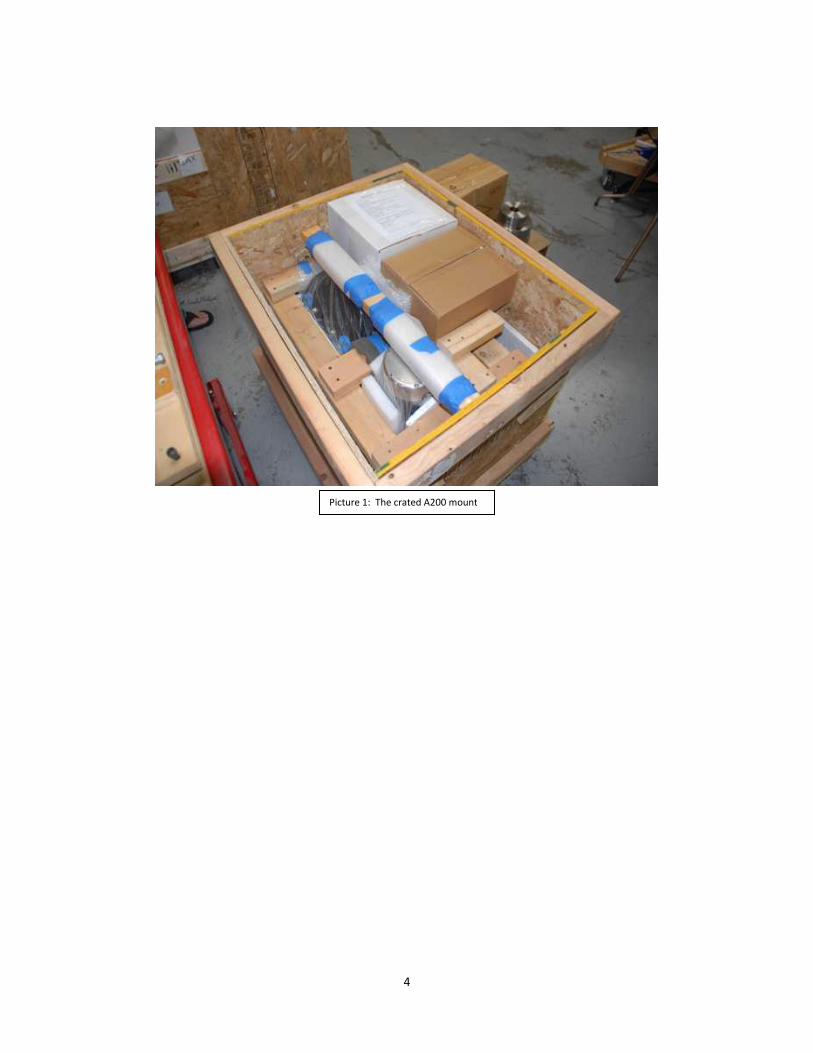
Unpacking and Crating The Ascension 200 comes in one crate as shown in picture 1. Shown in picture 2 are all the items in the crate.
Here is a list of all the items that come in the crate, also see Picture 2.
• RA Axis and the Mount Base
• Declination Axis
• Counterweight Shaft
• Counterweight Safety Stop (A200-148)
• RA Base to Pier Bolts (4X 3/8-24 x 1-1/2 SHC)
• Dec to RA Bolts (4X 1/2-13 x 1-1/4 BHC)
• 4 Communication Cables, 2X 4 pin and 2X 8 pin (gray cables with yellow tips), one of each per axis.
• PlaneWave Saddle (200919) or EZ Saddle (600182)
• Saddle Plate Mounting Hardware, 5x ¼-20x1-1/8 flat head or EZ Saddle Mounting Hardware, Mounting
Bolts,4X ¼-20x 7/8
• 24VDC Power Supply (#2099286)with AC power cord
• 4 Pin to Barrel Power Connector (adapts the power supply to the mount’s power input)
• Electronics Box and USB Cable
• Mounting Hardware for electronics box (2X ¼-20x3/8 SHC with plastic thumb screw and 4x plastic
washers)
• Hand Paddle and Cable
• CDROM of Software
4
Picture 1: The crated A200 mount

5
Installing Pier Make sure the pier is within a few degrees of true North. The azimuth adjustment on the mount base has +/-7.5
degrees so you need to be within that range. And be aware that magnetic North can be quite a bit off from true
North.
The base of the Ascension 200 has 4 mounting holes used to bolt the base of the mount onto a pier plate. Please
see picture 3 and note the orientation of North relative to the mounting hole pattern.
Picture 2: All of the major components that come with the A200HR mount.

6
Installing the Mount on the Pier or Tripod The mount is pretty heavy so it is best to do the installation in parts. It takes at least two strong people to lift the
Base/RA and the Dec axis. Here are the steps to install the mount on the pier.
1. Set the altitude to approximately the correct latitude for your location as it is difficult to move the latitude
adjustment several degrees when the mount is fully loaded. There are not any indications for the
latitude. To get the approximate latitude, place an inclinometer on the RA axis. The angle that RA axis is
above the horizon is equal to your local latitude. There are 5 latitude set points shown in picture 4 and
shown in table 1. PlaneWave will try to ship the mount already set approximately to your latitude, but if
you need to change the position of the latitude adjustment screw here is how it is done.
a. Loosen the blue altitude lock knobs on the either side of the mounts base side plates.
b. Rotate the altitude of the mount up so it is out of the way, then lock the blue altitude lock knobs
again. Make sure they are fairly tight as you do not want the RA axis to slip during this process.
c. Remove the 4 bolts on the side of the latitude adjustment bar
d. Slide the latitude adjustment bar to the correct position to get it into the correct latitude range
for your latitude. See table 1 and picture 4 to figure out the latitude ranges of each position.
e. Secure the latitude adjustment bar with the 4x socket head bolts
f. Rotate or lower the RA axis back into position so it butts up against latitude adjustment screw.
N
Picture 3: Shown here is the base of the A200 mount. The 4 corner holes are used to mount attach the
mount to the pier. The 4 mounting holes are clearance holes for 3/8” socket head cap screws.

7
g. Repeat step 1.
2. Place the mount base on top of the pier mounting plate as shown in picture 5. NOTE: Be sure to tighten
the blue latitude adjustment lock screws to keep the RA axis from moving when you lift it. It is easy to
smash your fingers!
N/A 0-20 Degrees Latitude Requires low latitude kit. Part #
Position 1 20-35 Degrees Latitude
Position 2 35-50 Degrees Latitude
Position 3 50-65 Degrees Latitude
Position 4 65-80 Degrees Latitude
Position 5 80-90 Degrees Latitude
Picture 4: Shows the various mounting latitude adjustment positions. See Table 1 above for the
specific ranges for each position.
Table 1 . PlaneWave will attempt to preset this for you, but in the event that you need to set it, the ranges for each position are listed
above

8
3. Use the 4x 3/8-24 socket head cap screws (provided) to secure the base of the A200 to the mounting
plate of the pier. Use an Allen wrench to make sure these are tight.
4. Rotate the right ascension axis so that the alignment pins are roughly horizontal and tighten the two RA
clutch knobs! This needs be done prior to installing the Dec Axis.
5. Install the Declination Axis. Lift the declination axis with at least two people as it is somewhat of an
awkward shape. You can see in picture 6 how two people can lift it. There are two stainless steel pins
that will hold the dec axis onto the RA axis while you get the bolts to secure it. Once it is mounted, secure
the axis with the 4x ½-13 button head cap screws provided.
Note: Make sure the clutches are tightened before you put the Dec Axis on the RA axis. This is done by
rotating the blue knobs shown in picture 5 clockwise. You only need to hand tighten.
Picture 5: Placing the Mount Base onto the pier base plate

9
Installing the Telescope on to the Mount Step 1: Install the counterweight shaft as shown in picture 8. It is the 20” long stainless steel shaft and it threads
into the bottom of the RA axis. Also install the 8” extension shaft if you have it. See table one below to know if
you need the 8” extension bar or not.
Picture 7: If you have to adjust the latitude with a fully loaded mount, you can have one person lift the
counterweight bar while you are adjusting the latitude knob. This makes it quite a bit easier.
Picture 6: Typical installation of the declination axis.

10
Step 2: Run motor cables through the mount. See Appendix C
(IMPORTANT: Install the counterweights on the mount before putting the telescope on the mount. You never
want to have the mount top heavy as the RA Axis can suddenly rotate due to gravity. Damage to the mount and
instruments mounted on it can occur as well as injury to anyone nearby.)
Step 3: Install the counterweights as shown in figure 9. If you have 18lbs and 40lbs counterweights, you should put
the lighter 18lbs counterweight on first. Below in table 1 is a list of the number of counterweights needed to
balance particular telescopes.
Picture 8: Installing the counter weight shaft

11
Step 3: Install the counterweight safety stop as shown in picture 10. This makes keeps the counterweight from
accidentally sliding off the counterweight shaft and injuring somebody.
Step 4: Run the accessory cables you will be using through the mount. This needs to be done prior to putting on
the PlaneWave Saddle Plate or the EZ Saddle. Examples of cables you may want to run are, USB cables or
Picture 10: Installing the counterweight safety stop.
Figure 9: Installing the counterweights
12
extensions to run CCD cameras. An AC extension cord is recommended as you will likely need AC power to power
the CCD cameras; a serial cable to run the PlaneWave EFA Kit. To install the cables see Appendix C.
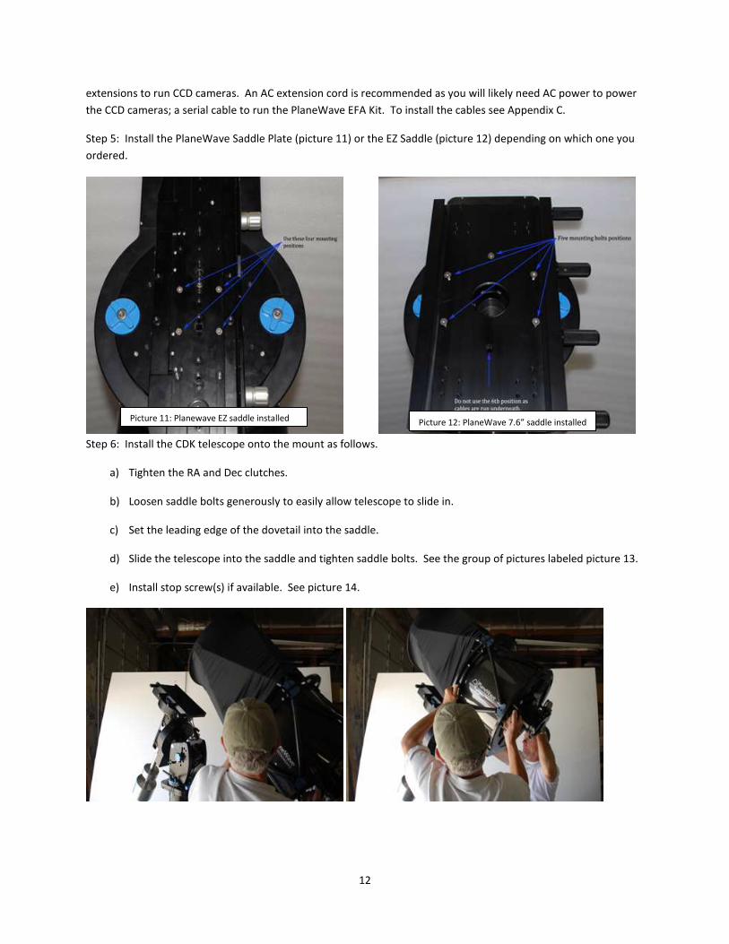
Step 5: Install the PlaneWave Saddle Plate (picture 11) or the EZ Saddle (picture 12) depending on which one you
ordered.
Step 6: Install the CDK telescope onto the mount as follows.
a) Tighten the RA and Dec clutches.
b) Loosen saddle bolts generously to easily allow telescope to slide in.
c) Set the leading edge of the dovetail into the saddle.
d) Slide the telescope into the saddle and tighten saddle bolts. See the group of pictures labeled picture 13.
e) Install stop screw(s) if available. See picture 14.
Picture 11: Planewave EZ saddle installed Picture 12: PlaneWave 7.6” saddle installed

13
CDK24 7X 40lbs counterweights and the 8” extension bar
CDK20 3X 40lbs counterweights and the 8” extension bar
CDK17 2x 40lbs counterweights and 1x 18 lbs
CDK12.5 1x 40lbs counterweight and the 8” extension bar
Balancing the Telescope After the telescope is installed, you will need to balance the system.
The first step will be to get the declination axis balanced.
1. When the telescope/mount system are in the configuration where the counter weights are pointed down
and the optical tube is pointed along the polar axis, as shown in picture 15, we can then loosen the blue
clutch knobs on the declination axis. Be sure to hold the telescope in case it is grossly out of balance!
With the clutch loosened, rotate the telescope toward the horizon. In this position, note when you
Picture 14: Once the telescope is installed, you can place a ¼-20 SHC screw in the hole at the end of the dovetail clamp as a safety stop.
Depending on the balance of the telescope, this option may not always be available.
Picture 13: Four pictures showing the installation of a CDK17 onto the A200 Mount using the PlaneWave 7.6” Saddle.
Table 2: List of the counterweights required for various CDK telescope apertures. It also includes whether the extension shaft is required or
not for a given CDK telescope.

14
release the optical tube whether the front rotates down or up. If the front rotates down then the
telescope is front heavy. If the front of the telescope rotates up, then it is back heavy.
2. If the telescope is front heavy then it needs to be moved back in the saddle plate. If the telescope is back
heavy then it needs to move forward in the saddle plate. To move the telescope in the saddle plate, first
put the telescope back in the position with the counterweights down and the tube pointed along the RA
axis as shown in picture 15. Then have two people hold the back of the telescope and then loosen the
saddle plate knobs to release the telescope. Slowly allow the telescope to slide back or push the
telescope forward depending which way you need to move it. Tighten the saddle plate knobs.
3. Repeat steps 1 and 2 until the declination axis is balanced.
Now the RA axis needs to be balanced. HOLD ON TO THE COUNTERWEIGHT SHAFT BEFORE PROCEEDING AND THE
COUNTERWEIGHT SHOULD ALREADY BE INSTALLED!
1. While holding the counterweight shaft, loosen the RA clutch knobs. The counterweight shaft is long and
gives you a lot of leverage to easily handle minor imbalances. Hold onto it in case the telescope is top
heavy and wants to fall. Rotate the RA Axis so the counterweight shaft is pointed toward the horizon.
2. Now notice whether the mount wants to rotate so that the telescope goes down or up. If the telescope
side goes down then the telescope side is heavy and the counterweights need to be moved out or down
the counterweight shaft. If the telescope rotates up, then the counterweights need to move up the
counterweight shaft.
3. When the counterweight shaft is in the horizontal position like this, you can loosen the counterweight
knobs and not have to worry about them sliding due to gravity and smashing your fingers. That really
hurts, so avoid it. While in the horizontal position, loosen the counterweight lock knobs so you can slide
Picture 15: The Ascension 200 HR mount

15
the weights in the appropriate direction to balance the telescope system. When the telescope is
balanced, the mount will not rotate with the clutches disengaged.
Picture 17: Balancing the RA axis by sliding the counterweights in or out.
Note on using the Clutches Having clutches is convenient for balancing the telescope system and is nice because it allows something to slip in
the event of hitting an obstruction. The clutches should be tightened so there is no slipping, but they should not
be over-tightened. They should only be finger tightened. Do not use a tool to tighten the clutches.
Installing the Electronics and Powering up the Telescope The electronics that we use on the Ascension
200 mount is the Sidereal Technology Servo II
Dual Axis Telescope controller. We package it
ourselves which includes the case, the cover,
the connectors and the cabling.
The board electronics as seen in picture 18
has two RA and Dec connectors, a USB port, a
serial port, a hand pad port, a 24VDC power
input port , a Limit Switch port and an
autoguider port.
The electronics board attaches to a bracket
mounted under the azimuth polar alignment
adjustment on the base of the mount, as seen
in picture 19. The electronics case is attached with two ¼-20 x 3/8” SHC screws with thumb knobs. Do not use
longer than 3/8” bolts as they can hit the electronics inside the case. There are also 4 nylon washers. On each
side, one washer goes between the case and the bracket while the other washer goes between the bolt head and
the bracket.
Picture 18: The Ascension 200 electronics case.
Picture 19: Bracket for mounting the electronics case. Picture 20: Attaching the electronics.

16
Installing the STI Control Software The installation of STI has several steps due to the fact that we have to talk to other ASCOM devices and interact
with other astronomy programs and with different Windows operating systems.
The DVD or memory stick that comes with the mount has this manual and the software needed to control the
A200 mount or other mounts using the PlaneWave controller. Below is a screen shot of the content on the DVD or
memory stick.
Here is an overview of the steps that need to be done for the installation.
• Load the ASCOM Platform
• Install SitechEXE
• Install .Net 1.1 (if not already installed on your computer)
• Replace SitechEXE with STI (this is the interface software)
• Load additional database files for scripting and plate solving
• Load USB Driver
• If using the Sky, load TeleAPI ASCOM driver.
1 - ASCOM Platform
Download the ASCOM Platform 6 from
http://ascom-standards.org/
On the right side of the website, there should be a window to download ASCOM Platform 6 as shown in the picture
below.

17
2 - SitechEXE Installer 0.5.1 - Installer for the old Sitech Interface and ASCOM drivers. This you will find on the
supplied DVD disk or supplied USB memory stick. Go into the directory SiTechEXE, then into the directory
SiTechEXE051, and select Setup.Exe as shown below and install.
* If you have never installed SitechEXE.exe on your computer, you need to do this before the new interface (STI)
will work.
* If the installer says that you need .Net 1.1, proceed to step 3. The link the installer gives you does not work.
3 - Install .Net 1.1, if installer above complains: If the download above went fine, then you already have .Net1.1
so proceed to step 4. If .Net 1.1 isn't already installed then here is the link to Microsoft to download it.
http://www.microsoft.com/downloads/en/details.aspx?FamilyID=262d25e3-f589-4842-8157-
034d1e7cf3a3&displaylang=en
If you’d rather, you can go to PlaneWave’s download site below we have a short cut to the long link above for
downloading .Net 1.1.
http://www.planewave.com/tech/download/
4 – STI (Sidereal Technology Interface): Here we will replace the original SiTechEXE with the newer STI.
Open the STI directory.

18
Open the directory for version 1.2.8 which is directory 128. If there is a higher number (more recent version) than
load that instead.
Select and copy SiTechExe.exe. Copy by right clicking your mouse and select COPY.
4 – Replace SiTechEXE with the new 1.2.8 version.
Navigate to "C:\Program Files\Common Files\ASCOM\Telescope\SiTech\" and paste the SiTechEXE.exe (1.2.8
version) which will overwrite the old version of SiTechEXE.exe. (to paste, right click and select paste).
5 – Additional files for Scripting and Auto-Mapping:
To get the complete capabilities of the Scripting and Auto-Mapping/Mount-Modeling, you need the additional files
that need to be placed in folder
"C:\Program Files\Common Files\ASCOM\Telescope\SiTech\"
Note: With Windows 7, replace "C:\Program Files\" with "C:\Program Files (x86)\"
In the STI directory, open “extra” as shown below.

19
In the directory “extra”, notice two executable programs, CalPointsXP and PlateSolveXP and one .dll file,
Interop.MaxIm.dll.
6- Copy CalPointsXP: Select and copy CalPointsXP.exe and paste it in the directory, "C:\Program Files\Common
Files\ASCOM\Telescope\SiTech\".
CalPointsXP creates an ordered list of (azimuth,altitude) pointing directions above a user defined local horizon.
This is used for making a script of an automated mount modeling run. Read CalPointsXP.pdf for more information
7- Copy PlateSolveXP: Select PlateSolveXP.exe and copy then paste it in the same directory, "C:\Program
Files\Common Files\ASCOM\Telescope\SiTech\".
PlateSolveXP locates for the coordinates of the center of the image used in automated mount modeling runs.
8-Copy Interop.MaxIm.dll: Select Interop.MaxIm.dll and copy then paste it in the same directory, "C:\Program
Files\Common Files\ASCOM\Telescope\SiTech\". This DLL is to allow SiTech and MaxImDL to talk to each other.
9-APM Catalog: The Plate Match Catalog is on the DVD folder "Starry Ridge\APM", Copy all 4610 files into the
folder "C:\Program Files\Starry Ridge\APM\".
Note: With Windows 7, replace "C:\Program Files\" with "C:\Program Files (x86)\"
10-USB Drivers: The USB drivers are on the DVD in the folder "USBdriver\CDM20602".
11-The Sky ASCOM Driver: If the Sky Planetarium software by Software Bisque is going to be used, then proceed
with loading the TeleAPI driver. The Sky ASCOM driver allows the Sky to talk with ASCOM devices.
On the DVD, select the folder “TheSkyTeleAPI” folder.
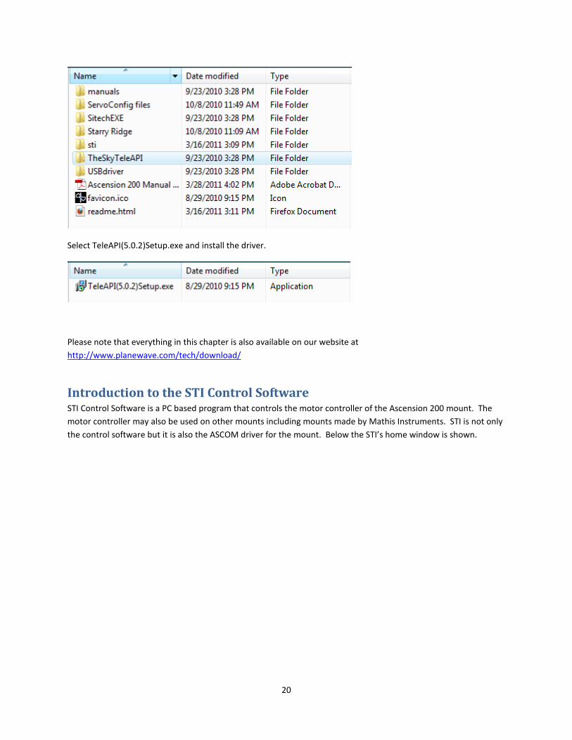
20
Select TeleAPI(5.0.2)Setup.exe and install the driver.
Please note that everything in this chapter is also available on our website at
http://www.planewave.com/tech/download/
Introduction to the STI Control Software STI Control Software is a PC based program that controls the motor controller of the Ascension 200 mount. The
motor controller may also be used on other mounts including mounts made by Mathis Instruments. STI is not only
the control software but it is also the ASCOM driver for the mount. Below the STI’s home window is shown.

21
Click "Edit Config" on the Mount-Panel of STI
Telescope Info Tab Note: Optical Info and Geographical Info need to be correct for some scripting features.
Mount Info Tab Below are the default settings for the A200

22
Scope Encoders Tab
Below are the default settings for the A200HR with High-Resolution-Axis-Encoders. For mounts with high
resolution encoders, like the A200HR, Cascade mode needs to be selected. If there are not High-Resolution-Axis-
Encoders than select Ignore.
Miscellaneous Tab
Set the Com Port for Communication with the SiTech Controller.

23
Enter the Camera Pixel-Count and Pixel-Size(Microns) and click "Calculate Field of View". Note: Optical Info must
be correct in the Telescope Info Tab for this calculation.
Polar Alignment, First Mount Model and Setting the Home Switches The Ascension 200 mount is a German Equatorial mount. That means that when the mounts polar axis is aligned
to the Earth’s axis, the mount need only track in one axis to counter act the rotation of the Earth.
Aligning the polar axis (also known as the Right Ascension axis) to the Earth’s axis is called polar aligning. With
non-computerized telescopes this can be done with a process called drift aligning. It is an iterative process which
is time consuming and takes a certain expertise.
Since the Ascension 200HR is a computerized mount with sophisticated software, the process is much easier. The
first step is to make a small mount model. This means you will align the telescope to about 6 known stars and then
the software will calculate the mounts polar misalignment.
At that point the mount can be adjusted in azimuth and in latitude manually to align the mount to the Earth’s polar
axis.

24
Steps before making your first mount model The mount and the telescope should be installed as done in previous chapters. This will mean the mount should
be within +/-5 degrees from true North in azimuth and you want the altitude to be within +/- 5 degrees too.
The first step is to power on the electronics and attach the computer to the USB port. Open STI. You may need to
find the correct serial port. To do this, you need to go to your computer’s DEVICE MANAGER. See Appendix C.
You will also need an aligned finder scope.
Making a Mount Model using Plate SolveXP In order to determine the mounts polar misalignment, you will need to create a small mount model. Since the
telescope is not polar aligned the pointing error all over the sky to different degrees. So we will start with making
a small quick mount model using the aligned finder scope. Then we will make an accurate automated mount
model to determine the mounts polar misalignment.
1 -Open STI.
2 – Open MaximDL and connect Maxim to your CCD camera.
3 – For convenience, connect Maxim DL to STI. Do this by pressing the Observatory button and selecting the tab
labeled Setup.
4 - Select the Chart menu from the list of options on the top of the STI window. Select “Show Sky Chart”. This will
open the sky chart window.

25
5 - Initialize the telescope to its home switches. Do this by selecting from the commands menu the Home
command. The Homing Operations Window will open. Press the “Initialize Scope Using Homing Switches” button.
The telescope will slew to the home switches.
6- Now select a bright star on the sky chart to align the telescope too. When you do so a window will pop up
telling you the name of the star. Now hit the GOTO button and the telescope will go approximately to the star you
selected. It is not expected that you will hit the star, the telescope is not polar aligned and the home switches
have not yet been trained.

26
7 - Now center the star in the finder scope using the hand pad. Don’t bother centering better than the finder
scope at this point.
Press the MODEL button and the InitPoint window will open. It will assume you are going to do a Simple Offset Init
shown by the yellow arrow below. There will be a 5 second count-down in case you wanted to do something else.
This positions the position of the telescope to the RA of the object.
8 - The window will close. Now press the MODEL button again, and this time when the InitPoint window pops up,
press the Load Cal Star button.
9 – Go back to the Sky Chart and choose another bright star and press GOTO. Center it in the finder scope again
and press MODEL. When MODEL is pressed and the InitPoint window opens, be sure to press the Load Cal Star

27
Button. Repeat this process so you have 3 stars on one side of the meridian and 3 stars on the other side of the
meridian.
10 - Now it is time to make your real mount model. Go to the Commands pull down menu and select Run Script at
the bottom.
11 –The Script window will open as seen below. The three arrows point to camera settings for doing an
automapping run. For this, you should do a 6 to 8 point mount model. So where is says, “How Many Cal Points”,
select 6. Exposure time of 3 seconds is reasonable. Binning set to 2.

28
12 - Once the parameters of the three arrows above are set, now press the “Make PointXP Run” button. This will
open a new program called CalPointsXP which will select the optimum positions for the 6 cal points. Note that the
CalPointsXP window does not need to stay open. And it will actually close itself after 60 seconds unless you check
the Keep Open box.
Whether CalPointsXP is open or closed, it will create a script in the Script window shown with the yellow arrow
below.
13 – Now press the PLAY button in the Script window. This will run the script and start the auto mapping run. This
will cause the telescope to slew to the first position, take an image, plate solve the image (accurately determine by
looking at the stars in the image, what the position of the telescope is), and add the position information to the
mount model.
The window that pops up is the PlateSolveXP window. Under “Status” the state of the system will be displayed.

29
14 – After the mount model is complete, press the PointXP button on STI and the PointXP window will pop up. In
the case below, there is a much larger model. In the lower left corner you will see the window labeled “Polar Axis
Alignment Error”

30
In the Polar Alignment Error window above, you will see the error is listed as “Move Down dd:mm:ss (degrees,
minutes and seconds)” and Move Right dd:mm:ss”. This means move the polar axis down and to the right by the
specified amount. In the case of the window above, the polar axis should be moved down 22 arc minutes and 53
arc seconds and moved to the right 6 arc minutes and 51 arc seconds.
15 – To move the polar axis in azimuth, loosen the six azimuth lock knobs shown in the figure below. Assuming the
polar axis needs to be moved to the right, then turn the Azimuth Adjustment Knobs to do so. First loosen the
Azimuth Adjustment knob on the left, then tighten the Azimuth Adjustment Knob on the right.
NOTE: Azimuth Adjustment Knob: 1 turn = .4 degrees (24 arc minutes).
NOTE2: For a Mathis mount, please see the included mount manual for this information.
In the example above, the polar alignment needs to be adjusted 6 arc minutes and 51 arc seconds. That is the
same as 6.85 arc minutes. See Appendix E. for conversion equation.

31
To calculate how many turns to turn the Azimuth Adjustment Knobs, take the polar misalignment in arc minutes
and divide it by 24 arc minutes. This will give you the number of turns. In our example,
6.85/24 = .28 turns. Just over a ¼ turn.
Once the azimuth has been adjusted, tighten up the Azimuth Lock knobs.
To move the polar axis in altitude, first loosen the Altitude Lock knobs. In our example, the polar axis needs move
down 22 arc minutes and 53 arc seconds or 22.88 arc minutes.
NOTE: Altitude Adjustment Knob: 1 turn = .5 degree (30 arc minutes)
To calculate how many turns to turn the Altitude Adjustment Knobs, take the polar misalignment in arc minutes
and divide it by 24 arc minutes. This will give you the number of turns. In our example,
22.88/24 = .95 turns. Just short of 1 turn.
Once the altitude has been adjusted, tighten up the Altitude Lock knobs.

32
This should complete your polar alignment. Now another mount model should be created. See the next chapter
to create another mount model.
Mount Model A mount model is a very accurate way of aligning the telescope to the sky. It improves the pointing and tracking of
the telescope system. It does this by comparing a number of RA/DEC positions in the sky to the measured position
of the telescope at those RA/DEC positions. The model has several different correction variables whose values can
be adjusted to minimize the RMS error of the true RA/DEC positions and the telescopes measured positions. A
reasonable model should be between 16 and 30 points. But it only takes 4 to 5 points to really start to point well.
Once a mount model is created it is used over and over again until something in the telescope system has changed.
The mount model is a file that can be saved and recalled after the telescope is powered on. The mount model can
be referenced initialized by one of three ways:
1. Home switches
2. Park position
3. Reference to the sky using Offset Init
Once a mount model has been created, a couple things should happen in order to save the mount model and
prepare STI for using the mount model in the future. First the home switch transition angles should be set. Once
this is done and you press OK, the current mount model is automatically saved as HomePointXP.PXP. When the
telescope is powered on and the telescope is initialized using the home switches, this mount model is
automatically opened.
The second thing to do after the first mount model is created is to set a part position. Once you have set a “park”
position and then “park” the telescope, the current mount model is saved as ParkPointXP.PXP. So the next time
you power up the mount, you will need to “unpark” the mount. When the mount is unparked the ParkPointXP.PXP
file will we automatically opened.
The third way is to manually open either ParkPointXP.PXP, HomePointXP.PXP or whatever name you created for a
mount model and use the “Offset Init” function to sync the model to the sky.
Things That May Invalidate the Mount Model Changing the collimation of the telescope, so make sure the telescope is collimated first.
Changing from a camera to a diagonal where the diagonal is not perfectly at 45 degrees.
Changing telescopes – if you change telescopes, you should create a new mount model.
Adding or removing weight from the telescope.
All of these above will affect the mount model. But it may be a small enough of an affect that you can ignore it.
You will have to using the telescope to find out. If the pointing accuracy is negatively impacted enough, you can
creat another mount model. You can even have multiple mount models, one for each equipment setup if you
need it.

33
Creating a Mount Model 1 -Open STI.
2 – Open MaximDL and connect Maxim to your CCD camera.
3 – For convenience, connect Maxim DL to STI. Do this by pressing the Observatory button in MaximDL and
selecting the tab labeled Setup. Under Telescope press the options button. Select SiTech from the options menu
and press connect.
4 - Select the Chart menu from the list of options on the top of the STI window. Select “Show Sky Chart”. This will
open the sky chart window.

34
5 - Initialize the telescope to its home switches. Do this by selecting from the commands menu the Home
command. The Homing Operations Window will open. Press the “Initialize Scope Using Homing Switches” button.
The telescope will slew to the home switches.
6- It is time to start an automapping run. This is an automated way of creating a mount model as you did in the
polar alignment process. From the Commands menu on STI, select Run Script.

35
7 –The Script window will open as seen below. The three arrows point to camera settings for doing an
automapping run. Since this is going to be the main model for the telescope set the number of stars to be at least
16 and no more than 30. Where is says, “How Many Cal Points”, select 16. Exposure time of 3 seconds is
reasonable. Binning set to 2 is also reasonable for 12 micron pixels or smaller. If the CCD camera has larger than
15 micron pixels, 1x1 binning should be used.
8 - Once the parameters of the three arrows above are set, now press the “Make PointXP Run” button. This will
open a new program called CalPointsXP which will select the optimum positions for the calibration points. Note
that the CalPointsXP window does not need to stay open. And it will actually close itself after 60 seconds unless
you check the Keep Open box.

36
Whether CalPointsXP is open or closed, it will create a script in the Script window shown with the yellow arrow
below.
9 – Now press the PLAY button in the Script window. This will run the script and start the auto mapping run. This
will cause the telescope to slew to the first position, take an image, plate solve the image (accurately determine by
looking at the stars in the image, what the position of the telescope is), and add the position information to the
mount model.
The window that pops up is the PlateSolveXP window. Under “Status” the state of the system will be displayed.

37
10 – After the mount model is complete, press the PointXP button on STI and the PointXP window will pop up.
11 – When the mount model is complete, set the home transition angles. You do this one axis at a time. Under
Commands list, select HOME. This will open the HOME dialog box as seen below.
12 – Notice that there are two Find Transition Angle buttons on the dialog box, one for Primary Axis (RA) and one
for Secondary Axis (DEC). Press the Find Transition Angle button for the Secondary Axis first. Don’t press the
button for the Primary axis until the Secondary axis is complete. A new number for the Transition Angle will be
displayed that is close to 90 degree but not exactly. Then press the Find Transition Angle for the Primary Axis.
When it is complete, the number should be something close to 270 degrees.

38
13 – Press the OK button and this will save the PointXP file as HomePointXP.PXP for future use.
14 – If desired, set a park position. Slew the telescope manually with the hand pad or the buttons on STI to the
approximate park position of the telescope. For roll off observatories, this is usually pointing the telescope in a
horizontal position so as to clear the roll off roof.
15 – Once the telescope is in its park position, hit the STOP button to turn off tracking. Then from the Commands
menu, select SET PARK. Once this is done, from the Commands menu, select PARK. This write the current mount
model to a file called ParkPointXP.PXP for future use.
Saving
Using the Telescope Once After Creating a Mount Model The intent of the STI control software is to control the operation of the mount, the use of the high resolution
encoders, homing features and to talk to other ASCOM devices. STI does not have an extensive database. It only
has fairly bright stars and Messier objects that are useful in setting up the mount. But for an extensive database, it
is assumed a planetarium software package will be used in conjunction with STI.
Park, Home and Saving Mount Models Once a mount model has been created a couple of things need to happen. You must train the home sensors and
you must set your park position. This enables the telescope to recover the mount model you created at a later
time.
Set Park
Park is a settable position. Park is a position that is convenient to park the telescope/mount system. An example
would be if you had a roll off observatory where the telescope has to be in a horizontal position to close the roll-off
roof.
To set the Park position:

39
1 – Create a mount model or open an existing mount model.
2 – Turn off tracking.
3 – Manually slew to the position that will be used as the park position.
4 – From the Commands pull down menu select, SET PARK.
5 – A window will pop up verifying that you really want to set the part position. Click YES.
Once this is done, the mount model will be saved as “default.prk”. This is convenient because it will open this
model automatically when you later un-park the telescope.
Unpark
Once the telescope has a mount model and the model has been saved for
Home
Once the mount model is created, you need to calibrate the home sensors. Notice that on the Homing Operations
Window shown below there are two buttons labels “Find Transition Angle”. One is for the Primary Axis (RA or AZ)
and the other is for the Secondary Axis (DEC or Alt).

40
To calibrate the home sensors do the following.
1 – After creating a mount model, open the Home Operations Window by selecting HOME from the Commands
drop down menu.
2 – On the Home Operations Window press the Find Transition Angle button on either the primary or secondary
axis. Only find the transition angle one axis at a time.
3 – When the transition angles have been found on both axes, press the OK button. This is important. By pressing
the okay button, the mount model is saved under the name, “default.hom”. This way later when you cycle power
on the mount and you Initialize using the Home switches, the mount will bring up that model.
Startup of the Mount When the telescope is up and running, meaning has been polar aligned and it has a mount model, then it is ready
for general use. Normally the telescope will be used in the evening and shut off during the day. This section talks
about how to turn on and turn off the telescope at the beginning and end of the night.
There are three ways to get up and running with an existing mount model. First you can UNPARK the telescope.
This only works if you parked the telescope before shutting down the last time the telescope was used. If it was
parked, then when selecting UNPARK, the previous mount model associated with the park position will be opened.
Once the telescope is un-parked the telescope will be aligned and ready to go.
Another method to start up is to initialize the telescope using is home sensors. This will only work if the home
sensors where calibrated previously. Assuming they have been, then once the telescope finds its home position, it
will recall the mount model associated with the home switches and will be aligned and ready to go.
The third option is to recall a previously saved mount model and then perform a sync to the sky.
Autoguiding There are two different ways to autoguide telescopes. One way is doing what is called relay guiding. This is where
the guide camera is connected to the motor control box and as the guide star drifts, the CCD camera sends guide

41
command directly to the motor control box. There is a port called Autoguider on the motor control box for this
use. But relay guiding is not recommended for the A200HR mount or any other mount with high resolution
encoders.
The other method of autoguiding which is recommended for the A200HR mount is pulse guiding also known as
ASCOM guiding. In this method, the guide star drifts on the guide camera and the camera control software notes
this movement (example MaximDL) and through ASCOM commands tells STI to make the appropriate corrections.
Pulse guiding is nice because it doesn’t use any additional cables and it works much better with the A200HR
because of the high resolution encoders. Relay guiding does not work well with the high resolution encoders, but
pulse guiding does.
To set up pulse guiding, all that needs to be done is to connect via ASCOM STI and the camera control software you
are using. This is done in the camera control software. For MaximDL you need to press the button showing the
observatory dome. That will open a window called Observatory. Press the Setup tab and under options select
SiTech. This will connect MaximDL to STI via ASCOM communication.

42
Appendix A – Dimensions
43
Appendix B – Notes the high resolution encoders The A200HR has built in high resolution encoders that are directly coupled to each axis. The encoder directly
underneath RA gear and the DEC gear. They are couple directly to the RA and DEC shafts so the encoders always
record the movement of the telescope whether the clutches are in engaged or not or even if the clutches slip.
The high resolution encoders are used for the position of the telescope and as a second servo loop for tracking.
The mount has anywhere from 5 to 10 arcseconds of peak-to-valley periodic error due to the worm gear and gear
train. But with the hi-res encoders the periodic error is essentially removed. The rms tracking error is between .14
to .22 arcseconds and it happens at a frequency of about 20 cycles per second.
If you notice rms tracking errors consistently about .25 arcseconds then something needs to be adjusted on the
gear train to improve this or the telescope balance needs to change.
Everything in telescopes is balancing act of many variables. For the stiffest possible mount, a very strongly
preloaded worm is needed. But this creates more friction and makes the rms tracking error go up. For the
smoothest tracking possible (the smallest rms tracking error) the worms needs a weaker spring force preload.
The right answer is somewhere in the middle that balances mount stiffness and tracking smoothness. The spring
loaded worms can be adjusted for spring tension if needed. The covers will need to be removed in order to access
the preload spring.
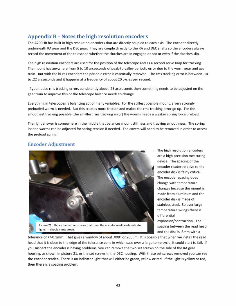
Encoder Adjustment The high resolution encoders
are a high precision measuring
device. The spacing of the
encoder reader relative to the
encoder disk is fairly critical.
The encoder spacing does
change with temperature
changes because the mount is
made from aluminum and the
encoder disk is made of
stainless steel. So over large
temperature swings there is
differential
expansion/contraction. The
spacing between the read head
and the disk is .8mm with a
tolerance of +/-0.1mm. That gives a window of about .008” or 200um. It is possible that when we install the read
head that it is close to the edge of the tolerance zone in which case over a large temp cycle, it could start to fail. If
you suspect the encoder is having problems, you can remove the two set screws on the side of the RA gear
housing, as shown in picture 21, or the set screws in the DEC housing. With these set screws removed you can see
the encoder reader. There is an indicator light that will either be green, yellow or red. If the light is yellow or red,
then there is a spacing problem.
Picture 21: Shows the two set screws that cover the encoder read heads indicator
lights. It should show green.

44
On the underside of each gear housing cover is a panel that can be removed. This panel houses the high resolution
encoder read head. If there needs to be adjustment, it can be done by removing this panel. Please contact
PlaneWave on instructions of adjusting the read head.
Appendix C – Running Cables Through-the-Mount The A200HR mount has the ability to easily run cable through the mount. For the motors, encoders and home
switches on the mount, this needs to be done. But also for other accessories that are on the telescope, it is very
convenient to do this too so there are no dangling cables that can tangle during operation. Usually having an
extension cord is a nice cable to run through the mount as having 110V on the telescope allows you to power
camera and the focuser and guide cameras.
In the figure below we show how to run the declination motor cables. Remove the cover that is pointed too in
picture 22 and run the cables down through the RA axis. There are retaining clips that can be used to fix the cables
in the cable channel on the side of the mount show in picture 23.
Picture 22: Showing the access cover that allows
cable routing through the RA axis.
Picture 23: Shows the cable retaining clips.

45
To run other cables through the mount it is easiest to do this by removing the telescope from the mount and
removing the dovetail from the mount. There is a hole going through the DEC axis and the top plate of the DEC
axis has a cable routing channel. Once the cables are routed you can put the dovetail saddle back on the top plate
of the DEC axis and the cables will be under the dovetail saddle. On the CDK20 and CDK24, the telescope dovetail
has slotted hole in it that allows you to run cables through the mount without taking the telescope off.
Once the cables have been dropped through the DEC axis, they will be accessible through holes on either side of
the stainless steel counter weight shaft holder at the bottom of the DEC axis. Pull the cable out on either side.
Route the cable up to the access hole at the interface point of the RA and DEC axes. Remove the access cover
shown in picture xx and push down the RA axis. The cable will come out the bottom of the RA axis.
When all the cables that need routing through the mount have been routed, secure the cables along the sides of
the DEC axis with the cable clips and put the access covers back on.
Picture 24: Shows routing of a 3 prong extension
cord through the RA axis.
Picture 25: Shows how a cable comes out of the
DEC axis and is then routed through the RA axis.

46
Appendix D – Converting sexegesmal to arcminutes and to degrees Sexagesimal (SG) is degrees, minutes and seconds. To convert from SG to degrees do the following:
SG (dd, mm, ss) -> degrees = dd + mm/60 + ss/3600
To convert SG to arc minutes:
SG (0deg, 22 min, 53 sec) = 22 + 53 / 60 = 22.88 degrees.
Appendix E – Glossary of Terms • Cone (or Cone Error): Cone is the angular error which measures the non-perpendicularity between the
optical axis and the DEC axis / Alt axis. If you had a telescope that had zero cone error and you could
induce the error by adding a 2” diagonal for an eyepiece that was not properly aligned. Say the diagonal
mirror you added was misaligned by 10 arcminutes, you would now have a telescope system with a cone
error of 10 arcminutes.
• Hub: Hub is the angular error which measures the non-perpendicularity between the RA and Dec axes or
Azimuth and Altitude for an Alt/Az mount.
Picture 26: Shows cables going through the mount.

47
• Offset Init or Offset Initialization: This defines the mounts position for one point in the sky. If you point
to a star in the sky and do an Offset initialization, then the telescopes relative position is defined as the
position of that star. This is usually done prior to creating a mount model.
• PlateSolve: Taking an image of a star field and through matching against a known database of stars,
defining the true center of the field very accurately. This is useful when creating a telescope mount
model as it yields a very accurate position of the mount.
• Polar Alignment: Equatorial mounts, like the Ascension 200, have two orthogonal axes. One of the axis is
called the Right Ascension axis or RA. If the RA axis is aligned to the Earth’s axis of rotation, then the
mount is said to be polar aligned. Polar Alignment is the act of polar aligning the mount. The advantage
of an equatorial mount is that in order to cancel out the rotation of the Earth, all that has to happen is to
have the RA axis track in the opposite direction at 1 rotation in 24 hours.
• Mount Model: A mathematical algorithm that corrects for repeatable mechanical, positional, and
atmospheric errors for a telescope mount. Mechanical errors would be flexure, non perpendicularity of
the RA and DEC axes and of the optical axis to the DEC axis. Positional errors would be polar
misalignment, not being perfectly level not having the position of the telescope on Earth perfectly correct.
Atmospheric error would be refraction as you change your altitude. By using 16 to 30 modeling points,
this algorithm can correct for these errors to improve the pointing of the telescope and the tracking.
• RMS: Stands for root mean square. It is a way of looking at a whole group of data and measure how far
the data as a whole deviates from the norm or from perfect. With telescope it is generally used as a
measurement of error. What is the RMS error of tracking or of a mirrors surface or of the pointing
accuracy of a telescope system.