ASCE OC Geo Institute - Dinner Presentation - 08-15-2017
53
Presented by: David Albus, RCE, GE
-
Upload
american-society-of-civil-engineers-orange-county-branch -
Category
Engineering
-
view
126 -
download
0
Transcript of ASCE OC Geo Institute - Dinner Presentation - 08-15-2017

Presented by:
David Albus, RCE, GE
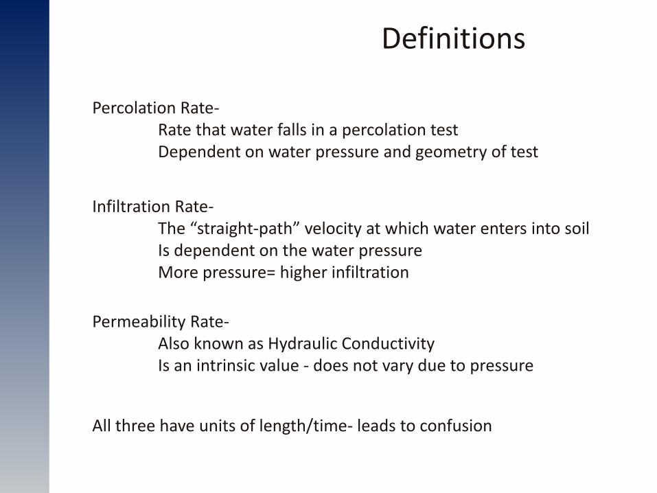
Definitions
Infiltration Rate- The “straight-path” velocity at which water enters into soil Is dependent on the water pressure More pressure= higher infiltration
Permeability Rate- Also known as Hydraulic Conductivity Is an intrinsic value - does not vary due to pressure
Percolation Rate- Rate that water falls in a percolation test Dependent on water pressure and geometry of test
All three have units of length/time- leads to confusion
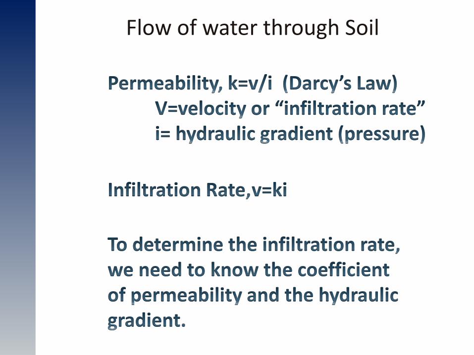
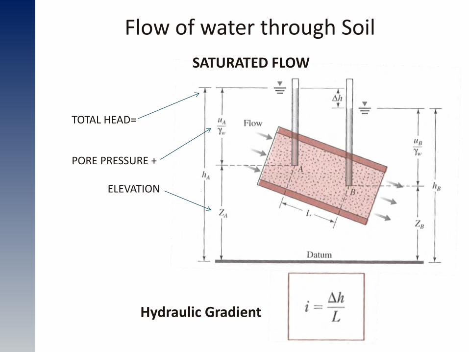
Flow of water through Soil
Flow of water through Soil
Hydraulic Gradient
TOTAL HEAD=
PORE PRESSURE +
ELEVATION
SATURATED FLOW

Flow of water through Soil
AdjacentElements
Element
K·i (X-direction)
K·i (Y-direction)
Boundary Flux
Change in Water Content
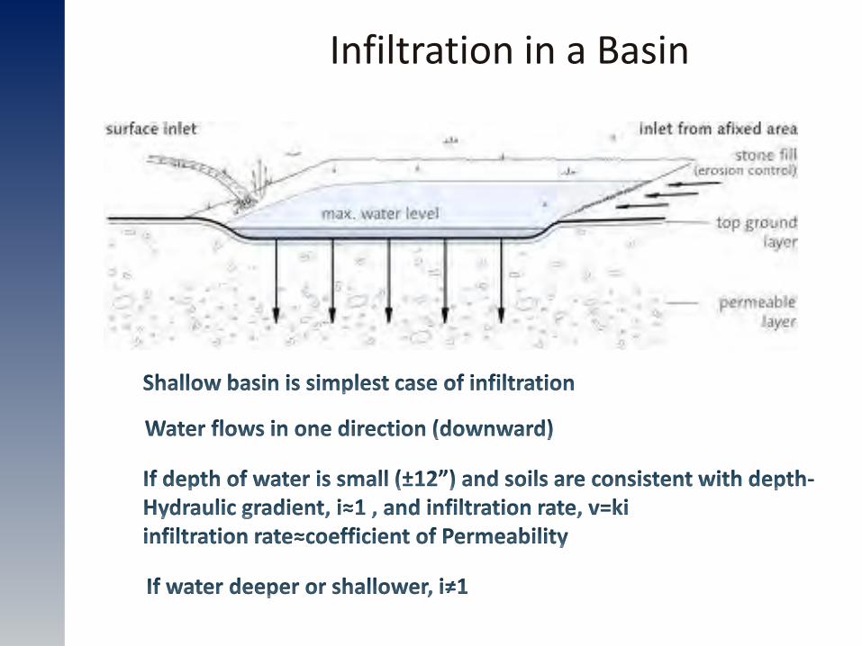
Infiltration in a Basin
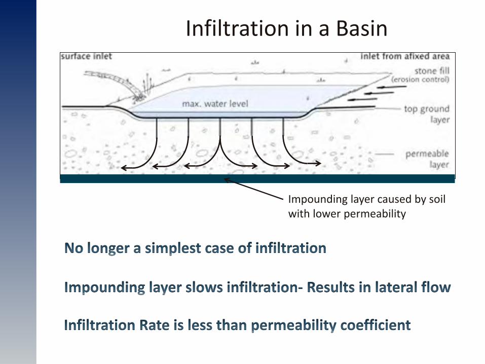
Infiltration in a Basin
Impounding layer caused by soil with lower permeability
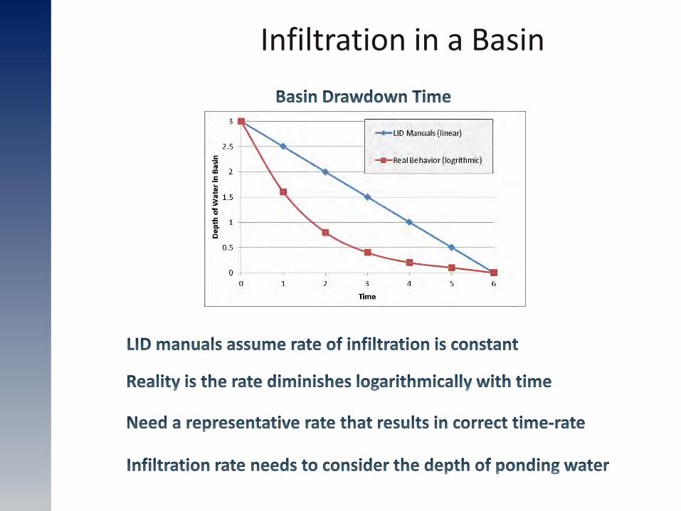
Infiltration in a Basin
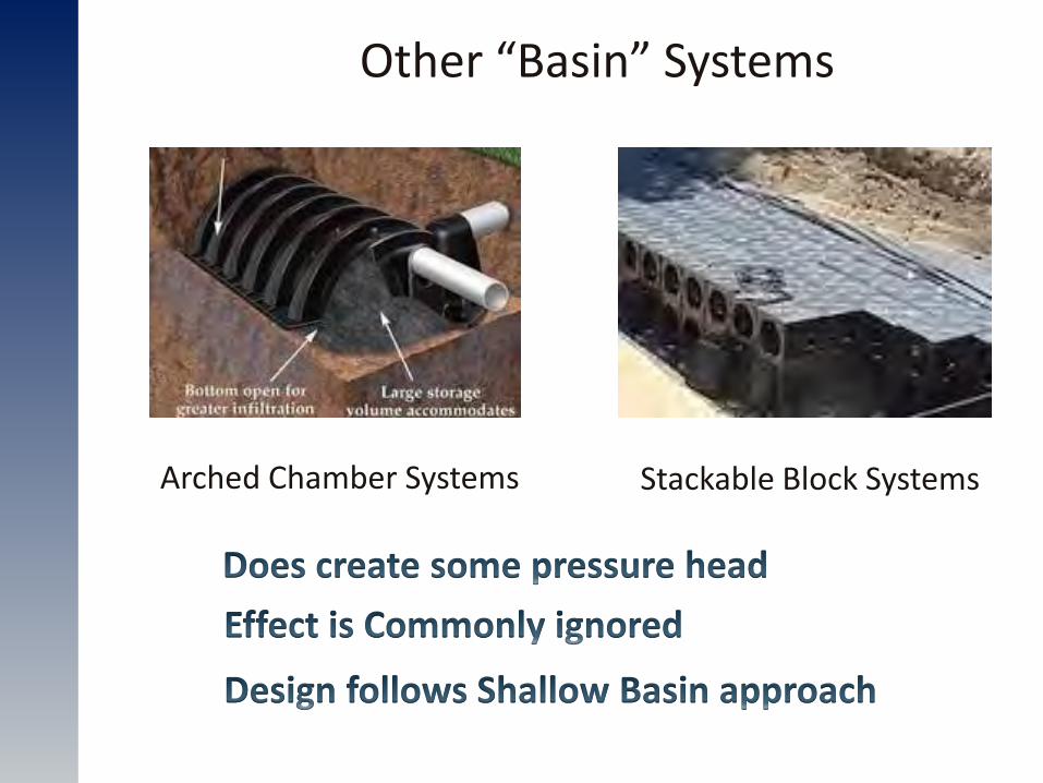
Other “Basin” Systems
Arched Chamber Systems Stackable Block Systems
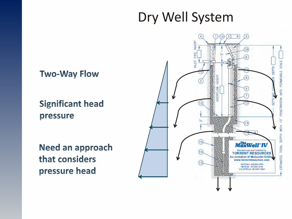
Dry Well System
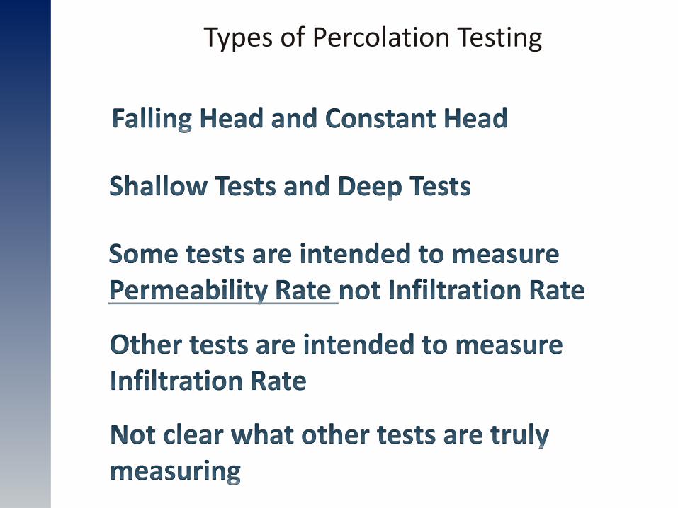
Types of Percolation Testing
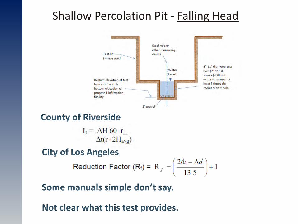
Shallow Percolation Pit - Falling Head
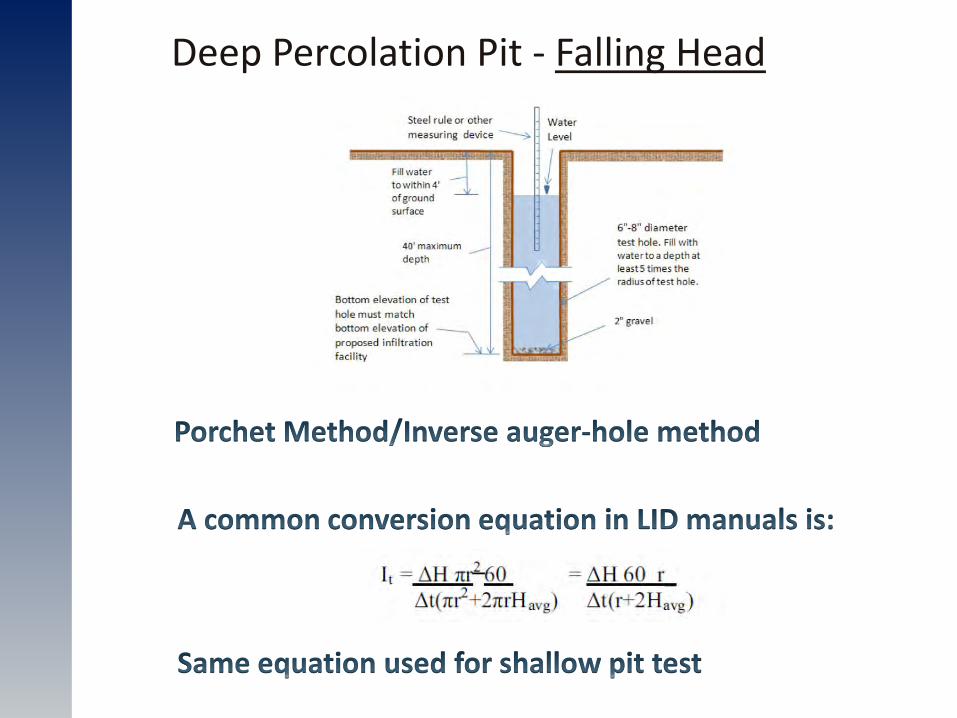
Deep Percolation Pit - Falling Head
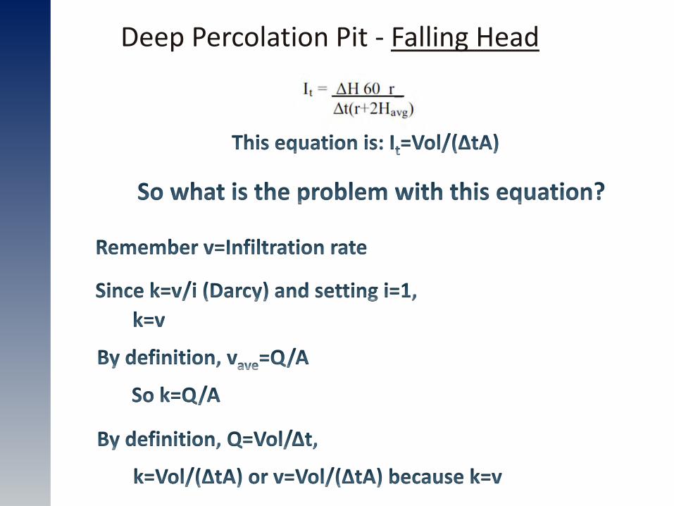
Deep Percolation Pit - Falling Head
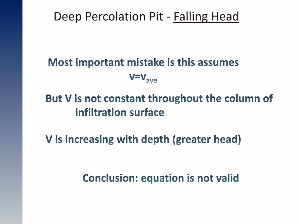
Deep Percolation Pit - Falling Head
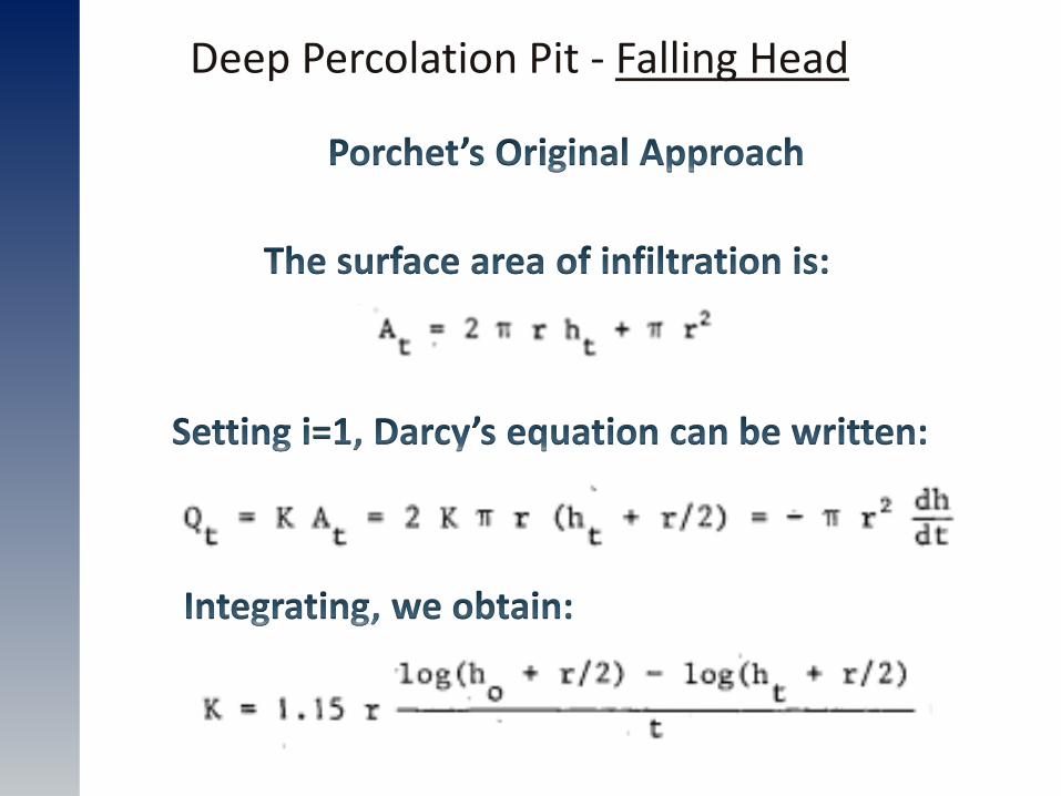
Deep Percolation Pit - Falling Head
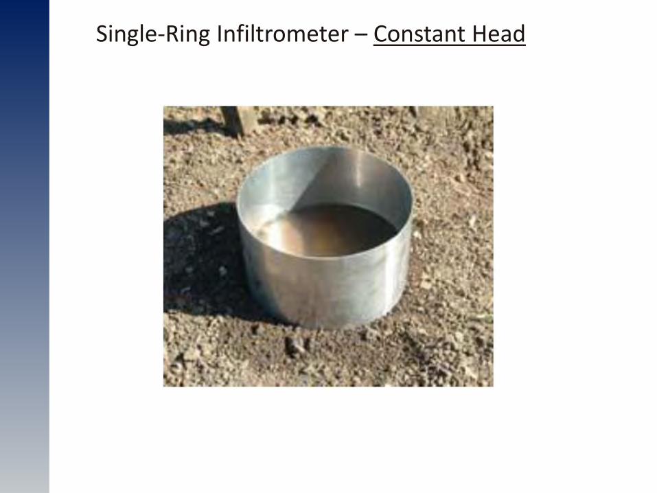
Single-Ring Infiltrometer – Constant Head
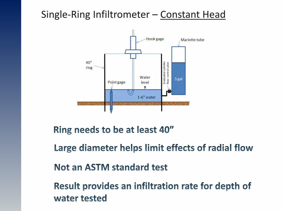
Single-Ring Infiltrometer – Constant Head
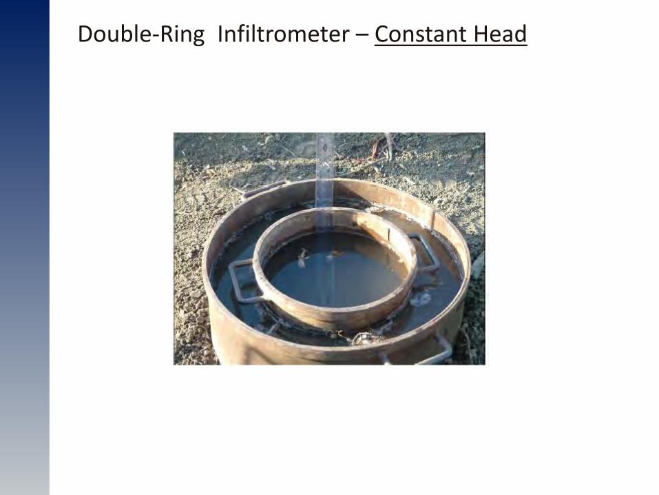
Double-Ring Infiltrometer – Constant Head
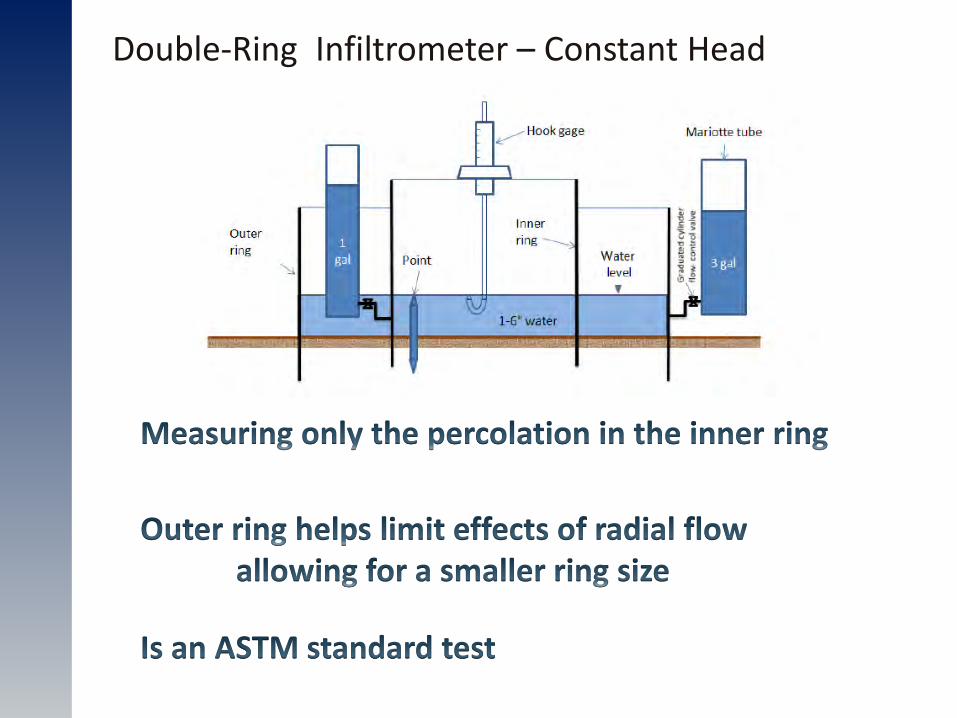
Double-Ring Infiltrometer – Constant Head
Double-Ring Infiltrometer – Constant Head
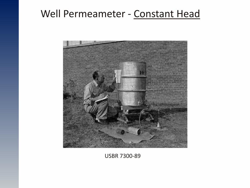
Well Permeameter - Constant Head
USBR 7300-89
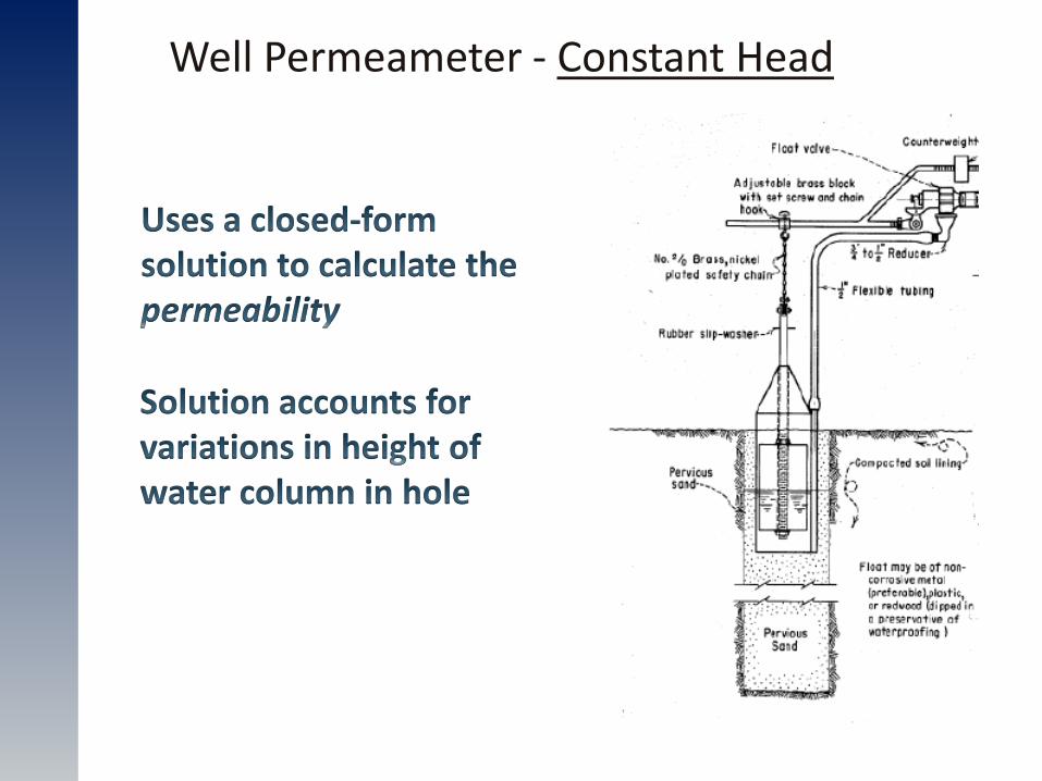
Well Permeameter - Constant Head
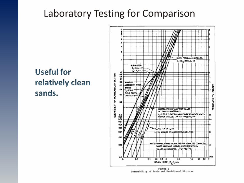
Laboratory Testing for Comparison
Laboratory Testing for Comparison
Laboratory Testing for Comparison
Laboratory Testing for Comparison
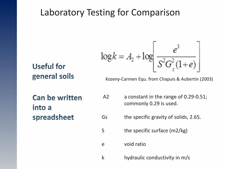
Kozeny-Carmen Equ. from Chapuis & Aubertin (2003)
A2 a constant in the range of 0.29-0.51; commonly 0.29 is used. Gs the specific gravity of solids, 2.65. S the specific surface (m2/kg) e void ratio k hydraulic conductivity in m/s
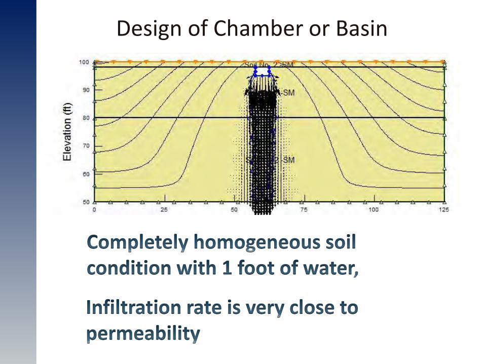
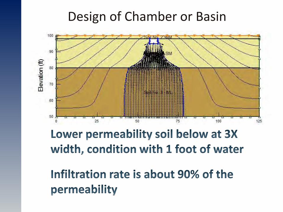
Design of Chamber or Basin
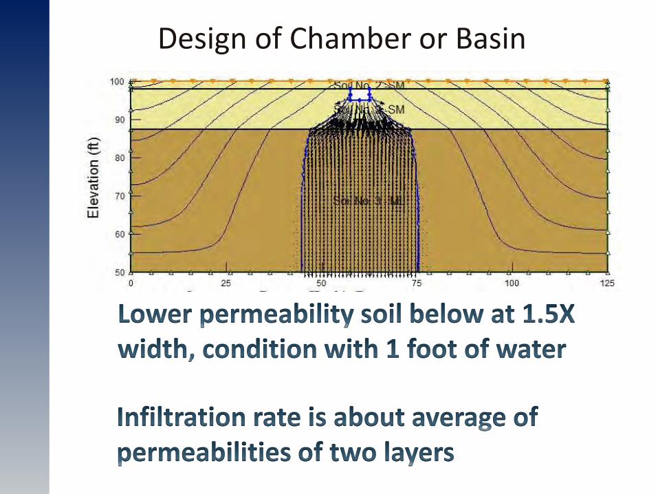
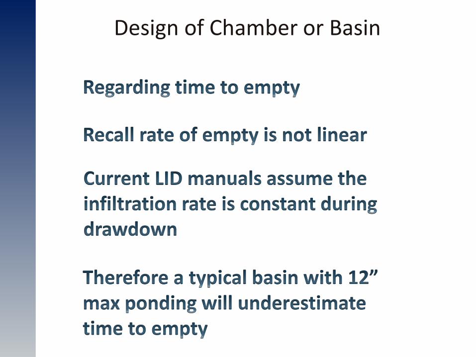
Design of Chamber or Basin
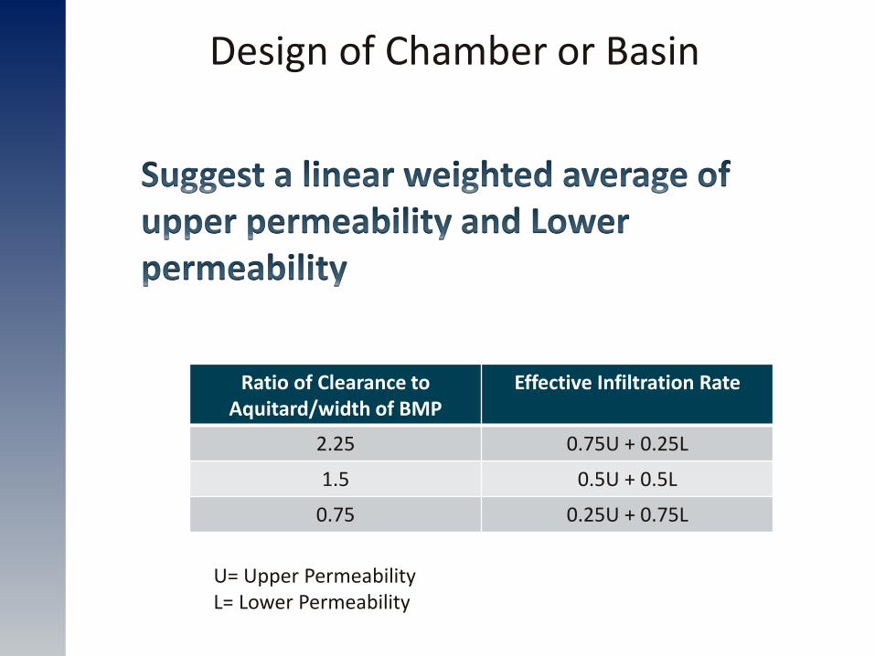
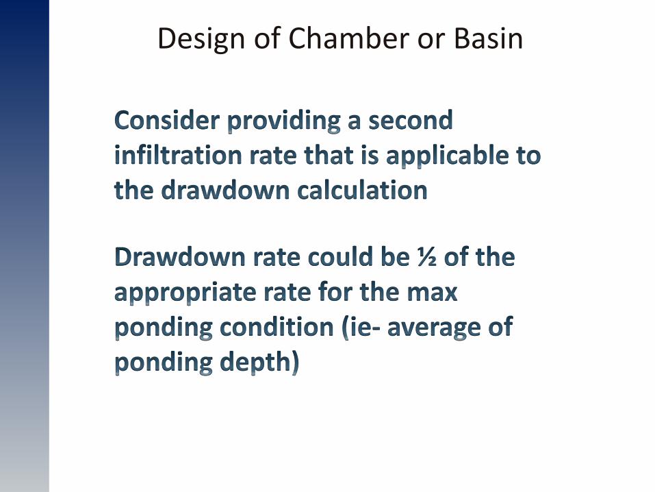
Design of Chamber or Basin
Design of Chamber or Basin
Ratio of Clearance to Aquitard/width of BMP
Effective Infiltration Rate
2.25 0.75U + 0.25L
1.5 0.5U + 0.5L
0.75 0.25U + 0.75L
U= Upper Permeability L= Lower Permeability
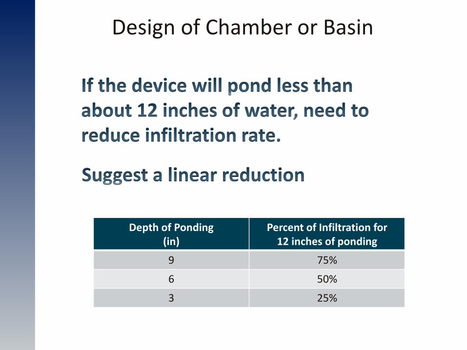
Design of Chamber or Basin
Depth of Ponding (in)
Percent of Infiltration for 12 inches of ponding
9 75%
6 50%
3 25%
Design of Chamber or Basin
Design of Chamber or Basin
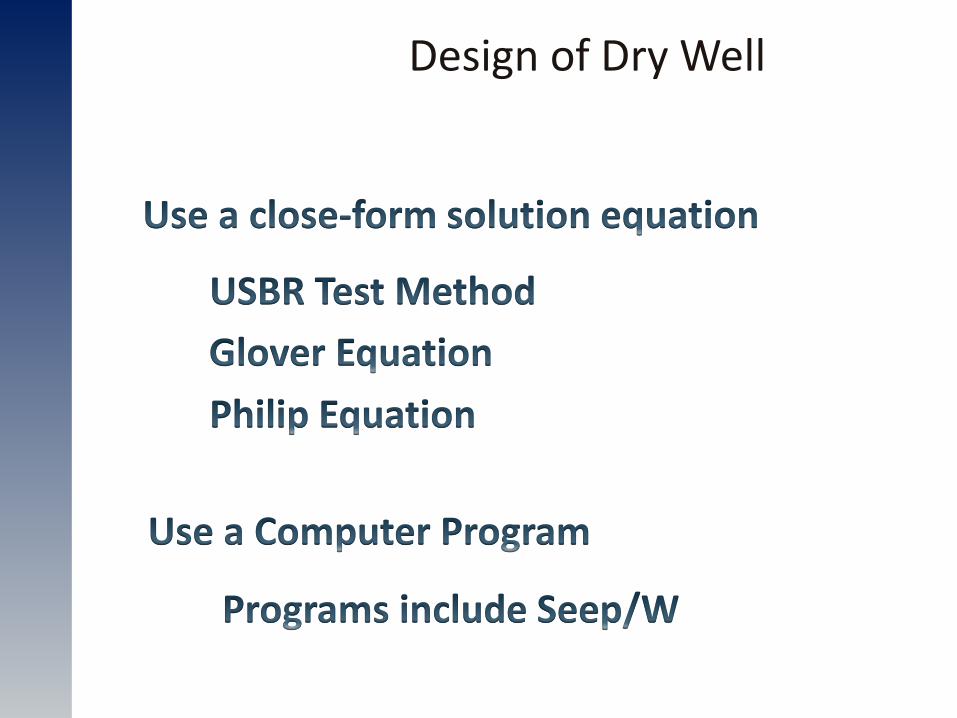
Design of Dry Well
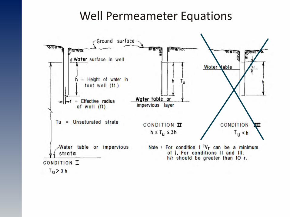
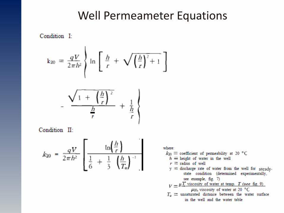
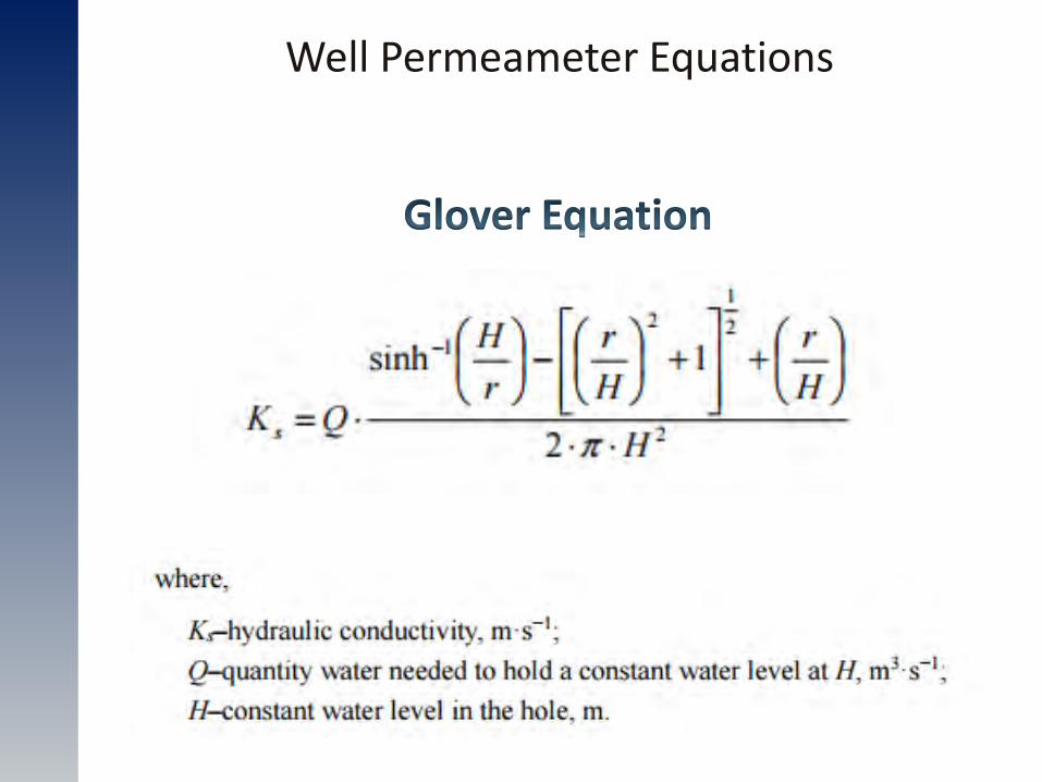
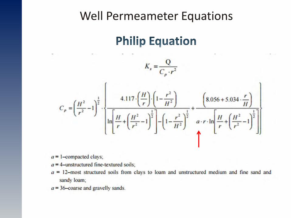
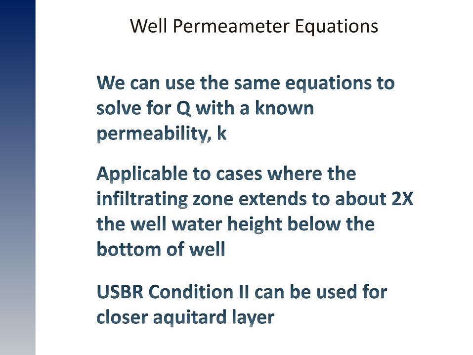
Well Permeameter Equations
Well Permeameter Equations
Well Permeameter Equations
Well Permeameter Equations
Well Permeameter Equations
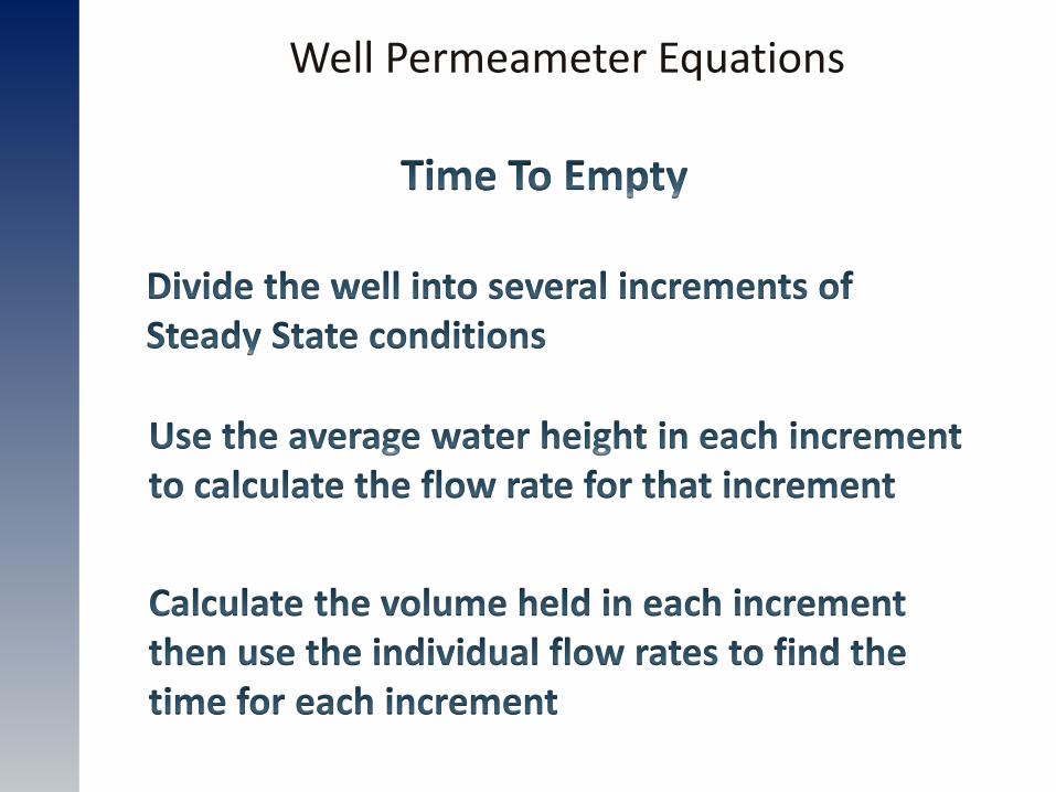
Well Permeameter Equations
Well Permeameter Equations
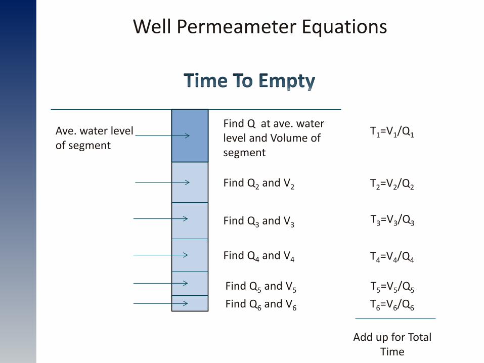
Find Q at ave. water level and Volume of segment
T1=V1/Q1
Find Q2 and V2 T2=V2/Q2
Find Q3 and V3 T3=V3/Q3
Find Q4 and V4 T4=V4/Q4
Find Q5 and V5 T5=V5/Q5
Find Q6 and V6 T6=V6/Q6
Add up for Total Time
Ave. water level of segment
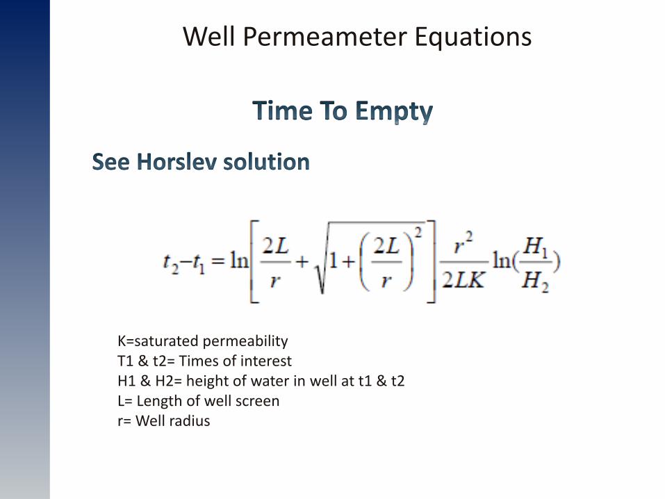
Well Permeameter Equations
K=saturated permeability T1 & t2= Times of interest H1 & H2= height of water in well at t1 & t2 L= Length of well screen r= Well radius
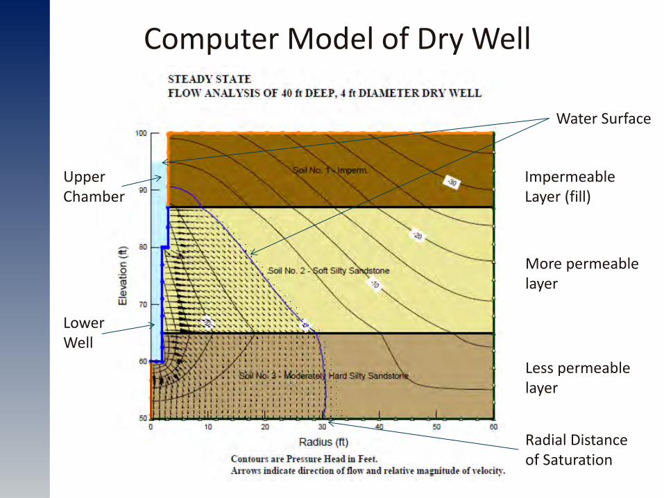
Computer Model of Dry Well
Water Surface
More permeable layer
Less permeable layer
Impermeable Layer (fill)
Radial Distance of Saturation
Upper Chamber
Lower Well
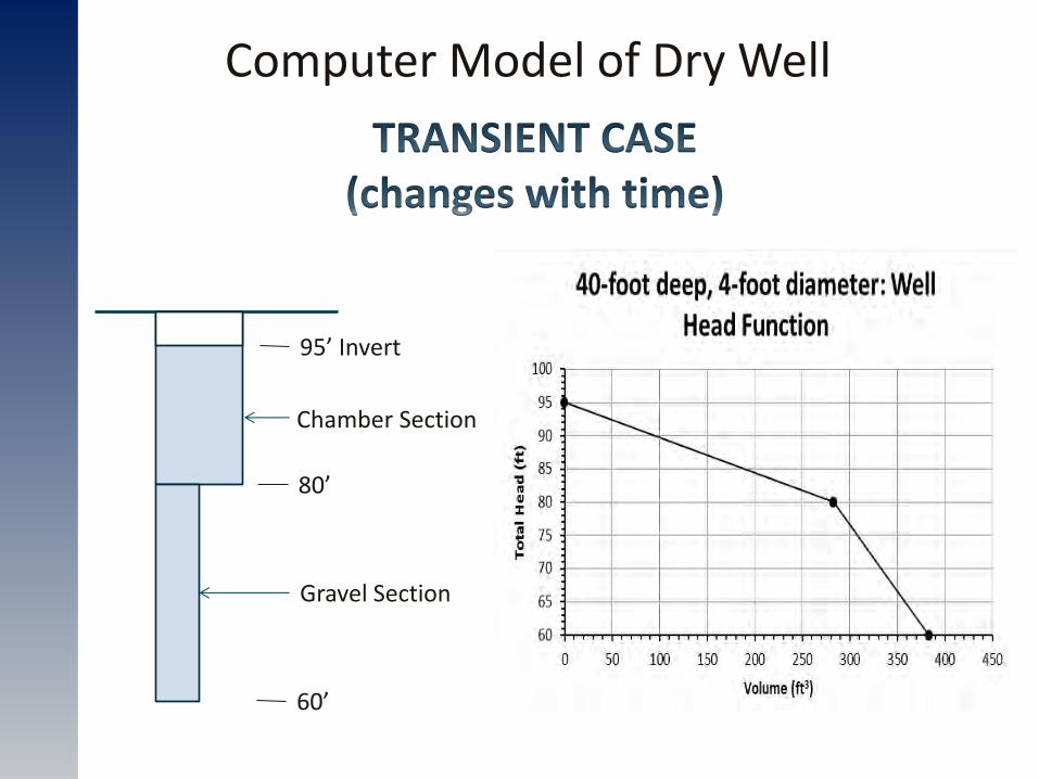
Computer Model of Dry Well
Chamber Section
Gravel Section
95’ Invert
80’
60’

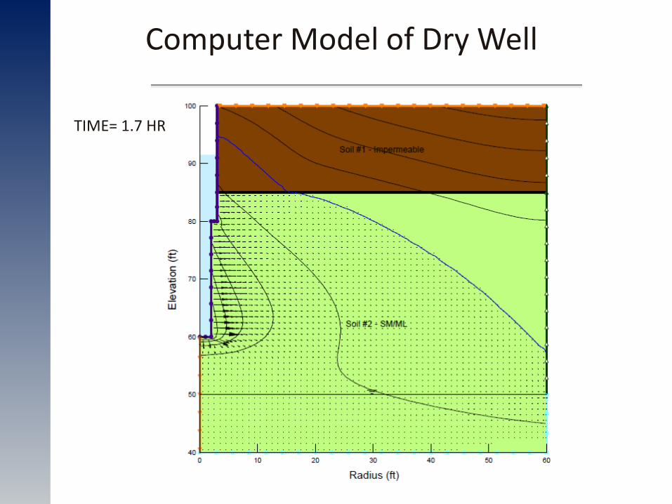
Computer Model of Dry Well
TIME= 0 HR
Groundwater
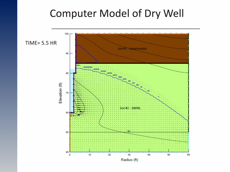
Computer Model of Dry Well
TIME= 1.7 HR
Computer Model of Dry Well
TIME= 5.5 HR

Computer Model of Dry Well
TIME= 9.7 HR
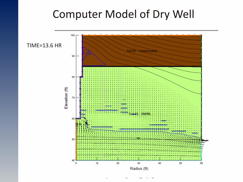
Computer Model of Dry Well
TIME=13.6 HR
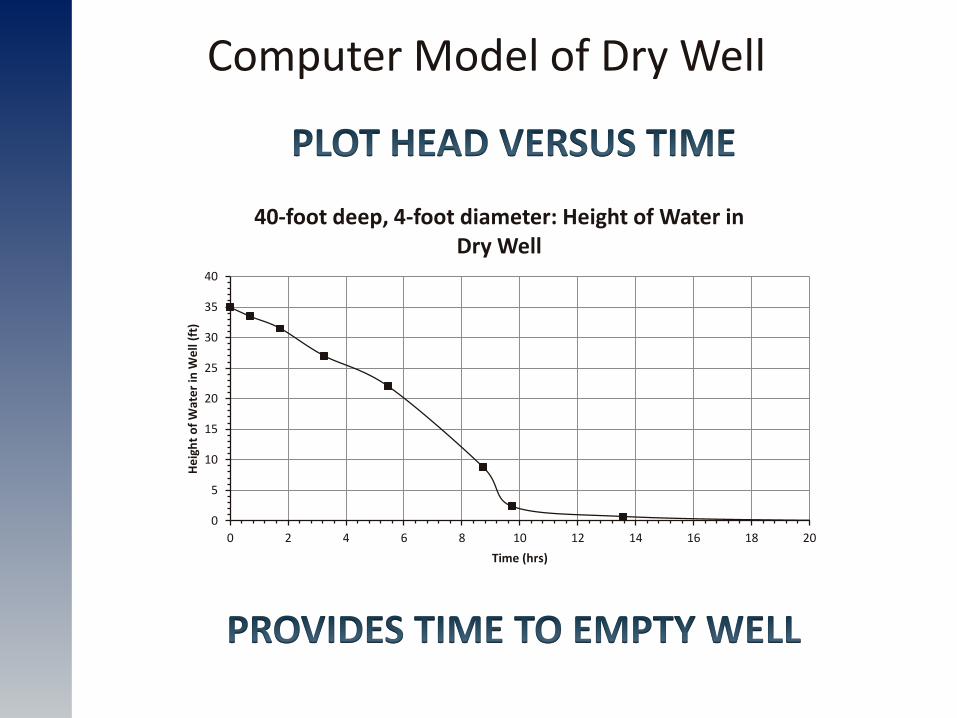
Computer Model of Dry Well
0
5
10
15
20
25
30
35
40
0 2 4 6 8 10 12 14 16 18 20
He
igh
t o
f W
ate
r in
We
ll (f
t)
Time (hrs)
40-foot deep, 4-foot diameter: Height of Water in Dry Well
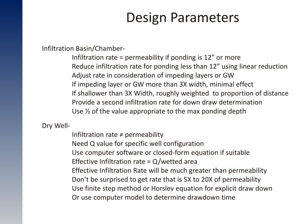
Design Parameters
Infiltration Basin/Chamber- Infiltration rate = permeability if ponding is 12” or more Reduce infiltration rate for ponding less than 12” using linear reduction Adjust rate in consideration of impeding layers or GW If impeding layer or GW more than 3X width, minimal effect If shallower than 3X Width, roughly weighted to proportion of distance Provide a second infiltration rate for down draw determination Use ½ of the value appropriate to the max ponding depth
Dry Well- Infiltration rate ≠ permeability Need Q value for specific well configuration Use computer software or closed-form equation if suitable Effective Infiltration rate = Q/wetted area Effective Infiltration Rate will be much greater than permeability Don’t be surprised to get rate that is 5X to 20X of permeability Use finite step method or Horslev equation for explicit draw down Or use computer model to determine drawdown time

Questions & Answers