AS5160&AS5160T user manual - Ӣ -...
28
AS5160 / AS5160T USER MANUAL Company information: www.vipercleaning.eu [email protected] Model: 50000398 / 50000403 VS10008-EU Rev 02 8 July 2016
Transcript of AS5160&AS5160T user manual - Ӣ -...

B
AS5160 / AS5160T
USER MANUAL
Company information:
www.vipercleaning.eu
Model: 50000398 / 50000403
VS10008-EU
Rev 02
8 July 2016

USER MANUAL ENGLISH
1
TABLE OF CONTENTS
INTRODUCTION ................................................................................................................................ 2 GUIDE PURPOSE AND CONTENTS ....................................................................................................................... 2
HOW TO KEEP THIS GUIDE ................................................................................................................................... 2
DECLARATION OF CONFORMITY ....................................................................................................................... 2
ACCESSORIES AND MAINTENANCE ................................................................................................................... 2
CHANGE AND IMPROVEMENT ............................................................................................................................. 2
SCOPE OF APPLICATION........................................................................................................................................ 2
MACHINE IDENTIFICATION DATA ...................................................................................................................... 2
TRANSPORT AND UNPACKING ............................................................................................................................ 3
SAFETY ................................................................................................................................................ 3 VISIBLE SYMBOLS ON THE MACHINE ............................................................................................................... 3
SYMBOLS THAT APPEAR ON THEINSTRUCTION FOR USEMANUAL .......................................................... 3
GENERAL SAFETY INSTRUCTION ....................................................................................................................... 4
MACHINE DESCRIPTION ............................................................................................................... 6
MACHINE STRUCTURE .......................................................................................................................................... 6
CONTROL PANEL .................................................................................................................................................... 7
DISPLAY WINDOW OF CHARGER INDICATON LIGHT .................................................................................... 7
TECHNICAL PARAMETERS ................................................................................................................................... 8
WIRING DIAGRAM .................................................................................................................................................. 9
OPERATING GUIDE ....................................................................................................................... 11 BATTERY CHECK/SETTING ON A NEW MACHINE ........................................................................................ 11
BATTERY INSTALLATION AND BATTERY TYPESETTING (WET OR GEL/ AGM) ................................... 12
BRUSH/PAD-HOLDER INSTALLATION AND UNINSTALLATION ................................................................ 13
ADJUSTING THE BALANCE OF SQUEEGEE ..................................................................................................... 13
SOLUTION OR WASHING WATER TANK FILLING ......................................................................................... 14
MACHINE START AND STOP ............................................................................................................................... 14
MACHINE OPERATION (SCRUBBERING AND DRYING) ............................................................................... 15
TANK EMPTYING .................................................................................................................................................. 16
AFTER USING THE MACHINE ............................................................................................................................. 17
MACHINE LONG INACTIVITY ............................................................................................................................ 17
FIRST PERIOD OF USE .......................................................................................................................................... 17
MAINTENANCE ............................................................................................................................... 18
SCHEDULED MAINTENANCE TABLE ............................................................................................................... 18
BATTERY CHARGING ........................................................................................................................................... 19
BRUSH/PAD CLEANING ....................................................................................................................................... 20
SOLUTION FILTER CLEANING ........................................................................................................................... 20
SQUEEGEE CLEANING ......................................................................................................................................... 21
SQUEEGEE BLADE CHECK AND REPLACEMENT .......................................................................................... 22
TANK AND VACUUM GRID WITH FLOAT CLEANING, AND COVER GASKET CHECK .......................... 23
MACHINE WORKING HOUR CHECK .................................................................................................................. 24
FUSE CHECK/REPLACEMENT ............................................................................................................................. 24
ACCESSORIES/OPTIONS ....................................................................................................................................... 25
TROUBLESHOOTING .................................................................................................................... 25
SCRAPPING ...................................................................................................................................... 25

USER MANUAL ENGLISH
2
INTRODUCTION
CAUTION!
Some general and detailed machine information is not included in this guide.
Please refer to Instruction for Use Manual on supplied CD-ROM reading by Adobe® Reader
®.
NOTE
The numbers in brackets refer to the components shown in Machine Description chapter.
GUIDE PURPOSE AND CONTENTS
The purpose of this Quick Start Guide is to provide the operator with all basic information to use the machine
properly. For information about technical characteristics, operation, machine inactivity, spare parts and safety con-
ditions etc., please refer to Instruction for Use manual on supplied CD-ROM.
Before performing any procedure on the machine, the operators and qualified technicians must read the Instruction
for Use manual. Contact our company in case of doubts concerning the interpretation of the instructions or for any
further information.
HOW TO KEEP THIS GUIDE
The Quick Start Guide must be kept near the machine, inside an adequate case, away from liquids and other sub-
stances that can cause any damage to it.
DECLARATION OF CONFORMITY
Declaration of Conformity is supplied with the machine and certifies machine conformity with the law in force.
NOTE
The copies of the original declaration of conformity are provided together with the machine
documentation.
ACCESSORIES AND MAINTENANCE
All the necessary operation, maintenance and repair procedures must be made by qualified personnel, our company
appointed repair center. ONLY original or approved spare parts and accessories can be used.
Contact our company customer service for any service or purchase of accessories or spare parts if necessary.
CHANGE AND IMPROVEMENT
We committed to continuous improvement of its products, the company reserves the right to the machine changes
and improvements without informing in additional.
SCOPE OF APPLICATION
The scrubber applies to commercial and industrial use. It is suitable for cleaning smooth and solid floor, operating
by a qualified personnel in safety circumstance. It is not suitable for outdoor use or carpet or rough floor cleaning.
MACHINE IDENTIFICATION DATA
The machine serial number and model name are marked on the serial label.
This information is useful. Use the following table to write down the machine identification data when requiring
spare parts for the machine.
MACHINE MODEL.............................................................................
MACHINE SERIAL NUMBER...........................................................

USER MANUAL ENGLISH
3
TRANSPORT AND UNPACKING
When the carrier delivers the machine, make sure the packaging and machine are both whole and undamaged. If
any damaged, make the carrier know the damage and before accepting the goods, reserve the right in compensation
of the damage.
Follow the instructions on packing strictly when unpacking the machine.
Check the package to ensure following items are included:
1. Technical documentations including Quick Start Guide manual, Instruction for Use Disk and on-board charger
manual if on-board charger is equipped.
2. Charger cable if on-board charger is equipped.
3. Two fuses, the low power circuit fuse (5A) and the Brush release fuse (20A).
SAFETY
The following symbols indicate potentially dangerous situations. Always read this information carefully and take
all necessary precautions to safeguard people and property.
VISIBLE SYMBOLS ON THE MACHINE
WARNING!
Read all the instructions carefully before performing any operation on the machine.
WARNING!
Do not wash the machine with direct or pressurized water jets.
WARNING!
Do not use the machine on slopes with a gradient exceeding that is defined in the specifi-
cation.
SYMBOLS THAT APPEAR ON THEINSTRUCTION FOR USEMANUAL
DANGER!
It indicates a dangerous situation with risk of death for the operator.
WARNING!
It indicates a potential risk of injury for people.
CAUTION!
It indicates a caution or a remark related to important or useful functions.
Pay attention to the paragraphs marked by this symbol.
NOTE
It indicates a remark related to important or useful functions.
CONSULTATION
It indicates the necessity to refer to the Instruction for Use manual before performing any
procedure.

USER MANUAL ENGLISH
4
GENERAL SAFETY INSTRUCTION
Specific warnings and cautions to inform about potential damages to people and machine are shown below.
DANGER!
• This machine must be operated by trained and authorized personnel according to guidance of the
manual.
• Before performing any cleaning, maintenance, repair or replacement procedure, read all the
instructions carefully, ensure to turn the machine OFF and disconnect the battery connector.
• Do not operate the machine near toxic, dangerous, flammable and/or explosive powders, liquids or
vapour. This machine is not suitable for collecting dangerous powders.
• Do not wear jewels when working near electrical components.
• Do not work under the lifted machine without supporting it with safety stands.
• When using lead (WET) batteries, they may emit inflammable gas under normal use, must keep
sparks, flames, smoking materials and radiating, illuminating and burning items away from the
batteries.
• When charging lead (WET) batteries, they may emit hydrogen gas which may cause explosive. Must
ensure the charging environment is well ventilated and away from naked flames.
WARNING!
• Check the machine carefully before each use. Ensure that all the components have been well
assembled before use. Or it may causes damages to people and properties.
• Before using the battery charger, ensure that the values of frequency and voltage indicated on the
machine serial number label match those of mains.
• Never move the machine by pulling the battery charger cable. Do not let the cable through a closed
door, or winding on sharp edges or corners. Do not run the machine on the battery charger cable.
Keep the battery charger cable away from heated surfaces.
Do not charge the batteries if the battery charger cable or the plug are damaged.
• To reduce the risk of fire, electric shock, or injury, make sure machine is off before leaving.
• Use or store the machine indoors in dry conditions, it is not allowed for outdoor use.
• The machine both storage and working temperature must be between 0 °C and +40 °C, the humidity
of air must be between 30% - 95%.
• Do not use the machine on slopes with a gradient exceeding as specification show.
• When using and handling floor cleaning detergents, follow the instructions on the labels of the
detergent bottles and wear suitable gloves and protections.
• Use brushes and pads supplied with the machine or defined in the manual. Using other brushes or
pads could reduce safety.
• In case of machine malfunctions, ensure that these are not due to lack of maintenance. If necessary,
request assistance from the authorized personnel or from an authorized Service Center.
• Take all necessary precautions to prevent hair, jewels and loose clothes from being caught by the
machine moving parts.
• Do not use the machine in particularly dusty areas.
Do not wash the machine with direct or pressured water jets, or with corrosive substances.
• Do not bump into shelves or scaffoldings, especially where there is a risk of falling objects.

USER MANUAL ENGLISH
5
• Do not lean liquid containers on the machine, use the relevant can holder.
• To avoid damaging the floor, do not allow the brush/pad to operate while the machine is stationary.
• In case of fire, use a dry powder fire extinguisher. Do not use liquid fire extinguishers.
• Do not remove or modify the machine stickers.
• Do not tamper with the machine safety guards and follow the ordinary maintenance instructions
scrupulously.
• Pay attention during machine transportation when temperature is below freezing point. The water in
the recovery tank and in the hoses could freeze and cause seriously damage to the machine.
• If spare parts need be replaced, order ORIGINAL spare parts from an Authorized Dealers or
Retailers.
• Return the machine to the Service Center if it doesn’t work as usual or it is in condition such as
damaged, placed outdoors, dropped into water.
• To ensure machine proper and safe operation, the scheduled maintenance shown in the relevant
chapter of this Manual, must be performed by the authorized personnel or an authorized Service
Center.
• The machine must be properly disposed of, because the presence of toxic-harmful materials
(batteries, etc.), which are subject to standards that require disposal in special centers (see Scrapping
chapter).
• This machine as a cleaning tool only, not for any other purpose use.
• Always keep the openings free from dust, hairs and any other foreign material which could reduce
the air flow. Do not use the machine if the openings are clogged.
• Use the machine only where a proper lighting is provided.
• This machine is not intended for use by persons with reduced physical, sensory or mental capabilities,
or lack of experience and knowledge, unless they have been given supervision or instruction
concerning use of the machine by a person responsible for their safety.
• Close attention is necessary when used near children.
• Children should be supervised to ensure that they do not play with the machine.
• While using this machine, take care not to cause damage to people or objects.

USER MANUAL ENGLISH
6
MACHINE DESCRIPTION
MACHINE STRUCTURE (as shown in Figure 1) 1. Recovery tank lid
2. Can holder
3. Handlebar
4. Control panel
5. Serial number plate/technical data
6. Squeegee lifting/lowering lever
7. Power supply cable holder
8. Power cable
9. Deck lifting/lowering pedal
a) Pedal position when deck is lifted
b) Pedal position when deck is lowered
10. Outlet cover
11. Squeegee knobs
12. Reset label
13. Squeegee vacuum hose
14. Squeegee
15. Squeegee balance adjusting knob
16. PA Connector
17. Rear steering wheels
18. Solution filter
19. Front wheels on fixed axle (A).
Driving wheels (B)
20. Brush/pad-holder
21. Brush/pad-holder deck
22. Recovery water drain hose
23. Solution tank
24. Hinge
25. Recovery tank
26. Filter support
27. Filler hose holder
28. Filter cover
29. N/A
30. Tank cover gasket
31. Float ball filter
32. Solenoid valve
(*): Optional
(A): Only for machine without traction
(B): Only for machine with traction
Figure 1
17 16 15 11 14 13
11
6
9
1218
25
24
23
21
20
19
22
27
28
30
31
32
4
5
7
8
10
9b9a
26
2 31

USER MANUAL ENGLISH
7
CONTROL PANEL (as shown in Figure 2) 33. Machine backward switch (B)
34. Safe switch
35. Ignition key (0 - I)
36. Discharged battery warning light (red)
37. Semi-discharged battery warning light (yellow)
38. Charged battery warning light (green)
39. Hour meter
40. Speed adjuster (B)
41. Flow increase switch
42. Solution flow indicator
43. Flow decrease switch
44. Brush/pad-holder release switch
45. Vacuum system switch
46. Brush/pad-holder and vacuum system switch
47. Charging red LED
48. Charging yellow LED
49. Charging green LED
50. Security cover of charging jack
51. Overload protector of brush
52. Overload protector of traction (B)
53. Overload protector of vacuum
54. Battery connector (red).
55. Tank safety cable
(*): Optional
(A): Only for machine without traction
(B): Only for machine with traction
DISPLAY WINDOW OF CHARGER INDICATON LIGHT (as shown in Figure 2)
1. At the beginning of charging, the red LED (47) of charger normally on. It is the first stage of charging.
2. After charging some time, the red LED (47) turns off, the yellow LED (48) turns on, this is the second stage of
charging.
3. After charging finish, the yellow LED (48) off, the green LED (49) turns on to indicate that the battery is fully
charged.
Figure 2
40
42
35
46 45 44
36
39
41
43
3837
54
55
34 3433
47 48 49
53 52 51 50
BRUSHTRACTIONVACUUM

USER MANUAL ENGLISH
8
NOTE
When charging, if the yellow LED (48) of charger is on, it may be caused by: Battery and
charger does not match, battery is not connected well, or output is short-circuited.
The red LED of charger flashing may be caused by charger internal short circuit.
TECHNICAL PARAMETERS
MODEL Units AS5160 AS5160T
Packing dimensions (Lx W x H) mm 1370x600x1220
Machine height mm 1000
Machine length mm 1310
Machine width (without squeegee) mm 550
Machine weight with empty tanks
(without batteries)
Kg 85 93
Gross vehicle weight (GVW) Kg 214.8 222.8
Shipping weight Kg 115 123
Solution tank capacity Liter 61
Recovery tank capacity Liter 61
Vacuum motor power Watt 350
Vacuum capacity mm H₂O 1200
Climbing capacity (Max) % 2%
Front wheel diameter mm 200
Rear wheel diameter mm 76
Sound level dB(A) 69±3
Solution/water Flow CL/M 0 – 240
Working width MM 510
Squeegee width MM 790
Brush/pad diameter MM 510
Brush motor power Watt 450
Brush speed Rpm 150
Brush/pad pressure(Max) Kg 27 23
Drive motor power Watt / 150
Working speed Km/h / 0-4.5
Voltage V 24V
Battery Ah 12V 100--115Ah
Battery charger V/A 24V 10A
Battery compartment size (L x W x H) mm 350X350X300

USER MANUAL ENGLISH
9
WIRING DIAGRAM (MACHINE WITHOUT TRACTION)
COMPONENTS WIRE ROD
BAT 24V BATTERIES RD1 RED/6AWG
CH BATTERY CHARGER RD2 RED/10AWG
EB1 CONTROL PANEL BOARD RD4 RED/20AWG
ES1 ELECTROMAGNETIC SWITCH 24V(BRUSH MOTOR) BK1 BLACK/6AWG
ES2 RELAY 24V(VACUUM MOTOR) BK2 BLACK/10AWG
F1 LOW POWER CIRCUIT FUSE BK3 BLACK/12AWG
F2 CIRCUIT BREAKER(BRUSH MOTOR) BK5 BLACK/20AWG
F3 BRUSH RELEASE FUSE BK6 BLACK/16AWG
F5 CIRCUIT BREAKER(VACUUM MOTOR) RD-BK RED-BLACK/20AWG
K1 KEY SWITCH BN1 BROWN/12AWG
M1 BRUSH MOTOR BN3 BROWN/20AWG
M2 VACUUM MOTOR BN-BK BROWN-BLACK/20AWG
EV SOLENOID VALVE BU BLUE/20AWG
SW1 SAFETY SWITCH(BRUSH) BU-BK BLUE-BLACK/20AWG
SW2 SAFETY SWITCH(BRUSH) YE YELLOW/20AWG
WH WHITE/20AWG
BATCH
K1
EV
M1 M2
EB1
ES1
ES2
F2 F5
RD1
RD2
RD2 BN1
BK3
BN3
RD2
BK3BK2 BK5
BK2
BK1
NC
F1
F3
SW1
RD4
RD-BK
BK2
RD2
BN3
J1
J2
SW2
IN1
8
9 1
16
RD4
ES1
ES2
BN-BK
YE
BU-BK
BN3
BU
BN3
RD-BK
BK6
BK6
2
6
7
3
4
5
10
11
14
15
12
13
IN1
BU
BK6IN2 J5
J4
IN2
BK6
BK5

USER MANUAL ENGLISH
10
WIRING DIAGRAM (MACHINE WITH TRACTION)
COMPONENTS WIRE ROD
BAT 24V BATTERIES RD1 RED/6AWG
CH BATTERY CHARGER RD2 RED/10AWG
EB1 CONTROL PANEL BOARD RD4 RED/20AWG
EB2 ELECTRONIC BOARD(TRACTION SYSTEM) BK1 BLACK/6AWG
ES1 ELECTROMAGNETIC SWITCH 24V(BRUSH MOTOR) BK2 BLACK/10AWG
ES2 RELAY 24V(VACUUM MOTOR) BK3 BLACK/12AWG
ES3 RELAY 24V(TRACTION SYSTEM) BK4 BLACK/14AWG
F1 LOW POWER CIRCUIT FUSE BK5 BLACK/20AWG
F2 CIRCUIT BREAKER(BRUSH MOTOR) BK6 BLACK/16AWG
F3 BRUSH RELEASE FUSE RD-BK RED-BLACK/20AWG
F4 CIRCUIT BREAKER(TRACTION SYSTEM) GN GREEN/20AWG
F5 CIRCUIT BREAKER(VACUUM MOTOR) GN-BK GREEN-BLACK/20AWG
K1 KEY SWITCH BN1 BROWN/12AWG
M1 BRUSH MOTOR BN2 BROWN/14AWG
M2 VACUUM MOTOR BN3 BROWN/20AWG
M3 DRIVE MOTOR BN-BK BROWN-BLACK/20AWG
EV SOLENOID VALVE BU BLUE/20AWG
SW1 SAFETY SWITCH(BRUSH/TRACTION) BU-BK BLUE-BLACK/20AWG
SW2 SAFETY SWITCH(BRUSH/TRACTION) OR ORANGE/20AWG
SW3 REVERSING SWITCH YE YELLOW/20AWG
VR1 SPEED POTENTIOMETER WH WHITE/20AWG

USER MANUAL ENGLISH
11
OPERATING GUIDE
WARNING!
On some points of the machine there are some adhesive plates indicating: ---- DANGER! ---- WARNING! ---- CAUTION! ---- CONSULTATION
While reading this Manual, the operator must pay particular attention to the symbols shown on the plates.
Do not cover these plates for any reason and immediately replace them if damaged.
BATTERY CHECK/SETTING ON A NEW MACHINE
WARNING!
The electric components of the machine can be seriously damaged if the batteries are either
improperly installed or connected. The batteries must be installed by qualified personnel only.
Set the function electronic board and the built-in battery charger according to the type of
batteries used (WET or GEL/AGM batteries).Check the batteries for damage before
installation. Disconnect the battery connector and the battery charger plug. Handle the
batteries with great care. Install the battery terminal protection caps supplied with the machine.
NOTE
The machine requires two 12 V batteries, connected
according to the diagram (Figure3).
The machine can be supplied in one of the following modes:
A) Batteries (WET or GEL/ AGM) already installed and charged
1. Check that the batteries are connected to the machine with the connector (54).
2. Insert the ignition key (35) and turn it to "I". If the green warning light (38) turns on, the batteries are fully
charged. If the yellow (37) or red warning light (36) turns on, the batteries must be charged (see the procedure in
Maintenance chapter).
B) Without batteries
1. Buy appropriate batteries (see the Technical Data paragraph).
2. For battery choice and installation, apply to qualified battery Retailers.
3. Set the machine and the battery charger according to the type of batteries (WET or GEL/ AGM), as shown in the
next paragraph.
Figure 3
12V
+-
12V
+ -

USER MANUAL ENGLISH
12
BATTERY INSTALLATION AND BATTERY TYPESETTING (WET OR GEL/ AGM)
According to the type of batteries (WET or GEL/AGM), set the machine and electronic board of the battery charger
as follows:
NOTE
When install new batteries please refer to figure 4 to adjust the DIP switches. Otherwise the bat-
teries may be damaged.
Machine setting 1. Turn the ignition key (35) to “I” and in the very first seconds of machine operation pay attention to the
following:
• If the first green warning light (38) is flashing, the machine is set to GEL/AGM.
• If the yellow warning light (37) is flashing, the machine is set to Discover EV AGM.
• If the red warning light (36) is flashing, the machine is set to WET.
2. If the setting need to be changed, perform the following procedure.
3. The factory setting is for discover EV AGM batteries. If the setting correspond to the battery installation, go to
step6 directly. Otherwise, follow next steps 4~5.
4. Remove the screws on control panel (C, Figure 4), then turn over the PCB (A Figure 4)to find the DIP switch
(B,Figure4) for setting battery type(WET or Discover EV AGM or GEL/AGM), (Refer to 1 or 2 or 3).
5. If the setting complete to the battery option. Install the screws on control panel.
Battery installation 6. Open the recovery tank cover (1) and check that the recovery tank (25) is empty; otherwise empty it with the
drain hose. (22)
7. Close the recovery tank cover (1).
8. Overturn the recovery tank (25) carefully.
9. The machine is supplied with cables suitable to install 2X12V batteries. Carefully put the batteries into the
compartment, then install them correctly.
10. Route and install the battery cable as shown in (Figure 3), then carefully tighten the nut on each battery termi-
nal.
11. Place the protection cap on each terminal, then connect the battery connector (54).
12. Carefully lower the recovery tank (25).
Battery charging
13. Charge the batteries. (See procedures in maintenance chapter).
Figure 4
1
WET BATTERIES
(NOTE: Turn the DIP switch 1
and 2 both to “OFF”. )
2
DISCOVER EV AGM
BATTERIES
(NOTE: Turn the DIP switch 1
to “ON” ; 2 to “OFF” .)
3
GENERAL GEL/AGM
BATTERIES
(NOTE: Turn the DIP switch 1
and 2 both to “ON” .)
WETB
A
C
D
DIS-EVGEL/AGWOTHER WETDIS-EUGEL/AGWOTHEROFF

USER MANUAL ENGLISH
13
BRUSH/PAD-HOLDER INSTALLATION AND UNINSTALLATION
NOTE
Install either the brush (A, Figure 5) or pad-holder (B and C, Figure5) according to the type of
floor to be cleaned.
CAUTION! Before installation or uninstallation of brush or pad-holder, make sure all the switches on ma-
chine are in off position and lifting up the squeegee from the floor. The operator must be
equipped with suitable personnel protection devices such as gloves to reduce the risk of acci-
dents.
Proceed as following:
1. Insert the ignition key (35) and turn it to "O".
2. Lift the deck by pressing the pedal (9).
3. If equipped, turn the speed adjuster (40) to idle by
turning it counter-clockwise.
4. Place the brushes (A, Figure5) or the pad-holder (B)
under the deck (21).
5. Lower the deck on the brushes/pad-holders by pressing
the pedal (9).
6. Turn the ignition key (35) to "I".
7. Brush/pad-holder and vacuum system switch (46).
8. Press one of the Brush/forward gear switch (34) to
engage the brush/pad-holder, then release it. If
necessary, repeat the procedure until the brushes/pad-holders are engaged.
9. If Step No.8 above proves to be difficult, use the manual method by turning the brush/pad-holder in the
direction opposite to the normal turning direction, and it can be taken off. (as shown in Figure 5)
WARNING! (Only for machine with traction)Turn the speed adjuster (40) counter-clockwise to drive the
machine at the minimum speed.
Slightly press the switch (34), otherwise the machine starts to move.
To engage the brush/pad-holder press the switch (34) which turns on the brush/pad-holder
motor.
10. To remove the brush/pad-holder lift the deck by pressing the pedal (9), then press the switch (44),the
brush/pad-holder will be remove.
ADJUSTING THE BALANCE OF SQUEEGEE 1. Install the squeegee and screw up the nut (H), then connect the vacuum hose (G) to the squeegee.
2. Adjust the squeegee by squeegee adjusting handle (A,
Figure6).
a) If there is gap between the ground and middle section
of rear squeegee blade (B), adjust the knob (A) in
counterclockwise direction (F) until all section of
rear squeegee blade good contact with ground, the
front blade touch the ground slightly.
b) If there is gap between the ground and both end
section of rear blade(C and D), adjust the knob (A) in
clockwise direction (E) until all section of rear blade
good contact with the ground, the front blade touch
the ground slightly.
Figure 5
A C B
Figure 6
DBCE FAH G
H

USER MANUAL ENGLISH
14
SOLUTION OR WASHING WATER TANK
FILLING
1. Open the water inlet cover (B, Figure 7).
2. Filling water or solution suitable for work performance
through the water inlet with filter.
The solution temperature must not exceed +104F
(+40°C).
3. Do not overfill the tank, refer to water level indicator (H)
for the water volume.
WARNING!
Use only low-foam and non-flammable
detergents, intended for automatic scrubber
applications.
MACHINE START AND STOP
Starting the machine
1. Prepare the machine as shown in the previous paragraph.
2. Insert the ignition key (A, Figure 8) and turn it to "I".
Check that the green warning light (B) turns on (charged
battery). If the yellow (C) or red warning light (D) turns
on, turn the ignition key back to “0” and charge the
batteries (see the procedure in Maintenance chapter).
3. Drive the machine to the working area:
• By pushing it with the hands on the handlebar (E) (only
for machine without traction).
• By pushing it with the hands on the handlebar (E) and
pressing the switch (F) to move forward, or pressing the
switch (F) together with the switch (G) to move
backward (only for machine with traction). The forward
speed can be adjusted with the adjuster (H).
4. Lower the squeegee (I) with the lever (J).
5. Lower the brush/pad-holder deck (K) by lifting the pedal
(L).
6. Press the brush/pad-holder switch (M) and the vacuum
system switch (N).
7. Press the washing water flow control switches (O) as
necessary, depending on the type of cleaning to be
performed.
8. Start cleaning:
• (only for machine without traction) by pushing the
machine with the hands on the handlebar (E) and
pressing the switch (F).
• (only for machine with traction) by pushing the machine
with the hands on the handlebar (E) and by pressing the
switch (F). If necessary, the forward speed can be
adjusted with the adjuster (H).
NOTE
To move the machine forward, press either
the left or right switch (F) or both.
Figure 7
H
A
G
ED
F
B
Figure 8
K IJL
FGFO
HA
D C B
E
M
N

USER MANUAL ENGLISH
15
Stopping the machine
9. Stop the machine by using the handlebar (E) (only for machine without traction). Stop the machine by
releasing the switches (F) (only for machine with traction).
10. Stop the brushes and the vacuum system by pressing the switch (M). The vacuum system stops after a few
seconds.
11. Lift the brush/pad-holder deck (K) by pressing the pedal (L).
12. Lift the squeegee (I) with the lever (J).
13. Turn the ignition key (A) to "0".
14. Make sure that the machine cannot move independently.
MACHINE OPERATION (SCRUBBERING AND DRYING)
1. Start the machine as shown in previous paragraphs.
2. While keeping both hands on the handlebar press the safety switch (F, Figure 8), then manoeuvre the machine
and start scrubbing/drying the floor.
3. If necessary, stop the machine then adjust squeegee according to section “Adjusting balance of squeegee”.
NOTE
For correct scrubbing/drying of floors at the sides of the walls, Suggests to go near the walls with
the right side of the machine (A and B, Figure 9) as shown in the figure.
CAUTION!
To avoid any damage to the floor surface, turn off the brushes/pad-holders when the machine
stops in one place.
Figure 9
A
B

USER MANUAL ENGLISH
16
Battery discharge during operation
Until the green warning light (A, Figure 10) stays on, the
batteries allow the machine to work normally. When the
green warning light (A) turns off, and the yellow warning
light (B) turns on, it is advisable to charge the batteries,
because the remaining charge will last for a few minutes
(depending on battery characteristics and work to be
performed). When the red warning light (C) turns on,
batteries are fully discharged. After a few seconds, the
brush/pad-holder is automatically tuned off, while the
(only for machine with traction) drive system stay on, to
finish drying the floor and drive the machine to the
appointed recharging area.
CAUTION!
Do not use the machine with discharged
batteries, to avoid damaging the batteries
and reducing the battery life.
TANK EMPTYING
An automatic float shut-off system (A, Figure 11) blocks
the vacuum system when the recovery water tank (B) is
full. The vacuum system deactivation is signaled by a
sudden increase in the vacuum system motor noise
frequency, also the floor has not dried.
CAUTION!
If the vacuum system turns off
accidentally (for example, when the float
is activated because of a sudden machine
movement), to resume the operation: turn
off the vacuum system by pressing the
switch (D, Figure 10), then open the cover
(C, Figure 11) and check that the float
inside the grid (A) has gone down to the
water level. Then close the cover (C) and
turn on the vacuum system by pressing
the switch (D, Figure 10).
When the recovery water tank (B, Figure 11) is full, empty
it according to the following procedure.
Recovery water tank emptying
1. Stop the machine.
2. Lift the brush/pad-holder deck (E, Figure 10) by
pressing the pedal (F).
3. Lift the squeegee (G) with the lever (H).
4. Drive the machine to the appointed disposal area.
5. Empty the recovery water tank with the hose (I).
Then, rinse the tank (B, Figure 11) with clean water.
Figure 10
Figure 11
C
BA
E
G
H
F
C B A
D
I
USER MANUAL ENGLISH
17
CAUTION!
When draining the wastewater, the vacuum
tube for waste must be folded (A, Figure 12)
and lowered to a lower position (B, Figure
12), and then open the lid of the vacuum tube
for waste to drain the water. Do not make the
outlet of the vacuum tube for waste face up-
ward to drain the water vertically. This is to
avoid wastewater spilling onto the operator.
6. Perform steps 1 to 4.
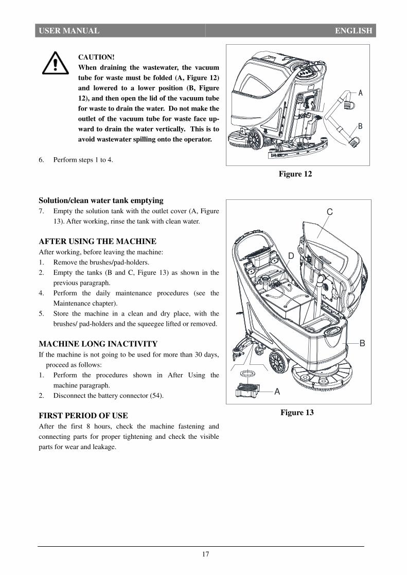
Solution/clean water tank emptying
7. Empty the solution tank with the outlet cover (A, Figure
13). After working, rinse the tank with clean water.
AFTER USING THE MACHINE
After working, before leaving the machine:
1. Remove the brushes/pad-holders.
2. Empty the tanks (B and C, Figure 13) as shown in the
previous paragraph.
4. Perform the daily maintenance procedures (see the
Maintenance chapter).
5. Store the machine in a clean and dry place, with the
brushes/ pad-holders and the squeegee lifted or removed.
MACHINE LONG INACTIVITY
If the machine is not going to be used for more than 30 days,
proceed as follows:
1. Perform the procedures shown in After Using the
machine paragraph.
2. Disconnect the battery connector (54).
FIRST PERIOD OF USE
After the first 8 hours, check the machine fastening and
connecting parts for proper tightening and check the visible
parts for wear and leakage.
Figure 13
Figure 12
D
C
B
A
A
B

USER MANUAL ENGLISH
18
MAINTENANCE
WARNING!
Maintenance procedures must be performed after the machine is turned off and the battery
charger cable is disconnected. In addition, carefully read the safety chapters in the manual.
All scheduled or extraordinary maintenance procedures must be performed by qualified personnel or an authorized
Service Center. This manual only describes the general and common maintenance procedures.
For other maintenance procedures that are not in below maintenance schedule table, please refer to the Service
Manual that can be consulted at any our company Service Center.
SCHEDULED MAINTENANCE TABLE
CAUTION!
The procedure marked with (1) must be performed when the machine is used after 9 hours for
the first time. The procedure marked with (2) must be done by Service Center that qualified by
our company.
Procedure
Daily, after each
use
Weekly semiannually
Yearly
Battery charging
Squeegee cleaning
Brush/Pad-holder cleaning
Tank cleaning
Tank sealing strip inspection
Float ball filter cleaning
Squeegee blade check and replacement
Cleaning water filter cleaning
Suction filter cleaning
WET battery fluid level check
Screw and nut tightness inspection (1)
Brush/Pad-holder carbon brush check or re-
placement
(2)
Suction motor carbon brush check or replace-
ment
(2)
Drive system motor carbon brush check or
replacement (only for machine with traction)
(2)
USER MANUAL ENGLISH
19
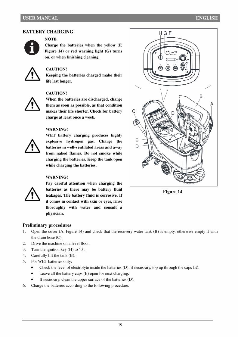
BATTERY CHARGING
NOTE
Charge the batteries when the yellow (F,
Figure 14) or red warning light (G) turns
on, or when finishing cleaning.
CAUTION!
Keeping the batteries charged make their
life last longer.
CAUTION!
When the batteries are discharged, charge
them as soon as possible, as that condition
makes their life shorter. Check for battery
charge at least once a week.
WARNING!
WET battery charging produces highly
explosive hydrogen gas. Charge the
batteries in well-ventilated areas and away
from naked flames. Do not smoke while
charging the batteries. Keep the tank open
while charging the batteries.
WARNING!
Pay careful attention when charging the
batteries as there may be battery fluid
leakages. The battery fluid is corrosive. If
it comes in contact with skin or eyes, rinse
thoroughly with water and consult a
physician.
Preliminary procedures
1. Open the cover (A, Figure 14) and check that the recovery water tank (B) is empty, otherwise empty it with
the drain hose (C).
2. Drive the machine on a level floor.
3. Turn the ignition key (H) to "0".
4. Carefully lift the tank (B).
5. For WET batteries only:
• Check the level of electrolyte inside the batteries (D); if necessary, top up through the caps (E).
• Leave all the battery caps (E) open for next charging.
• If necessary, clean the upper surface of the batteries (D).
6. Charge the batteries according to the following procedure.
Figure 14
D
B
G FH
E
D
C
A

USER MANUAL ENGLISH
20
Battery charging with battery charger installed
on the machine
7. Connect the battery charger cable (A, Figure 15) to the
electrical mains (G) (the electrical mains voltage and
frequency must be compatible with the battery charger
values shown on the machine serial number plate (F).
When the battery charger is connected to the electrical
mains, all machine functions are automatically cut off.
If the red warning light (B) on the battery charger
control panel stays on, the battery charger is charging
the batteries.
8. When the green warning light (C) turns on, the battery
charging is completed.
9. When the battery charging is completed, disconnect the
battery charger cable (A) from the electrical mains (G)
and wind it round its housing (D).
10. Carefully lower the tank.
NOTE
For further information about the operation
of the battery charger (E, Figure 15), see the
relevant Manual.
BRUSH/PAD CLEANING
CAUTION!
It is advisable to use protective gloves when cleaning the brush/pad because there may be sharp
debris.
1. Remove the brush/pad from the machine, as shown in the Use chapter.
2. Clean and wash the brush/pad with water and detergent.
3. Check that the brushes/pads are in working condition and not excessively worn; if necessary replace them.
SOLUTION FILTER CLEANING 1. Drive the machine on a level floor.
2. Ensure that the machine is off and the ignition key (35)
has been removed.
3. Emptying the solution tank (Advice).
4. Remove the transparent cover (D, Figure 16), then
remove the filter strainer (E). Clean and install them on
the support (F).
NOTE
The filter strainer (E) must be correctly
positioned on the housing (H) of the support
(F).
Figure 15
VACUUM TRACTION BRUSHCB
E
D
A
G
F
Figure 16
H
ED
E
G
F

USER MANUAL ENGLISH
21
SQUEEGEE CLEANING
NOTE
The squeegee must be clean and its blades must
be in good conditions in order to get a good
drying.
CAUTION!
It is advisable to wear protective gloves when
cleaning the squeegee because there may be
sharp debris.
1. Drive the machine on a level floor.
2. Turn the ignition key (A, Figure 17) to "0".
3. Lower the squeegee (B) with the lever (C).
4. Loosen the knobs (D) and remove the squeegee (B).
5. Disconnect the vacuum hose (E) from the squeegee.
6. Clean the steel or the aluminum squeegee (Figure18). Clean
the compartments (A) and the hole (B) especially. Check
the front blade (C) and the rear blade (D) for integrity, cuts
and tears; if necessary replace them (see the procedure in
the following paragraph).
7. Assemble the squeegee in the reverse order of disassembly.
Figure 17
Figure 18
B
AD
C
A
A
C
E
B
DD
USER MANUAL ENGLISH
22
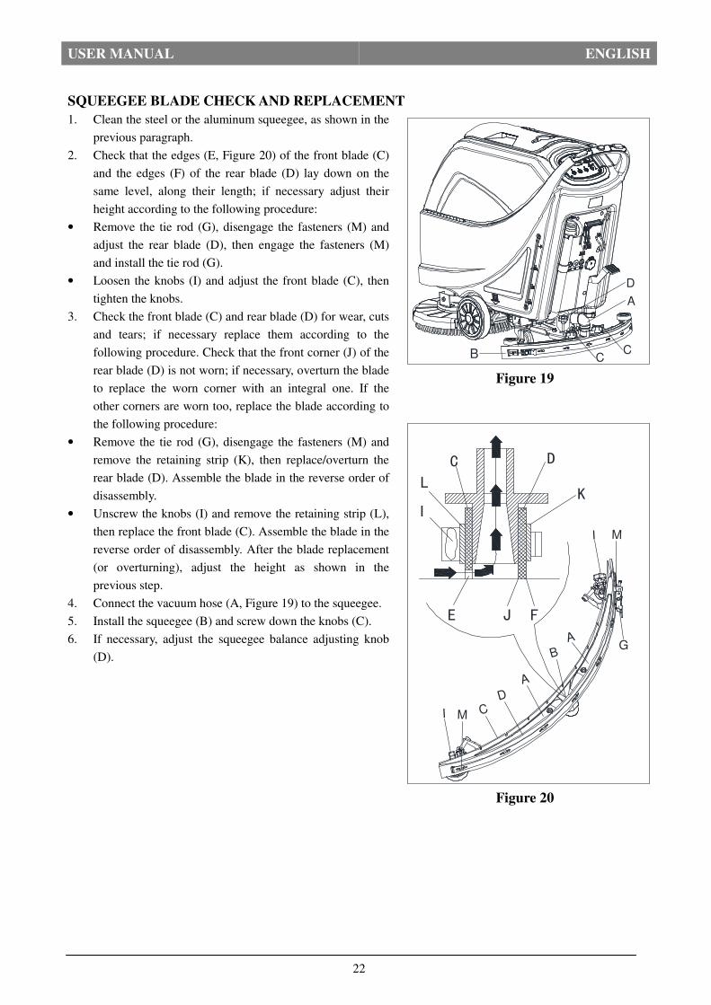
SQUEEGEE BLADE CHECK AND REPLACEMENT
1. Clean the steel or the aluminum squeegee, as shown in the
previous paragraph.
2. Check that the edges (E, Figure 20) of the front blade (C)
and the edges (F) of the rear blade (D) lay down on the
same level, along their length; if necessary adjust their
height according to the following procedure:
• Remove the tie rod (G), disengage the fasteners (M) and
adjust the rear blade (D), then engage the fasteners (M)
and install the tie rod (G).
• Loosen the knobs (I) and adjust the front blade (C), then
tighten the knobs.
3. Check the front blade (C) and rear blade (D) for wear, cuts
and tears; if necessary replace them according to the
following procedure. Check that the front corner (J) of the
rear blade (D) is not worn; if necessary, overturn the blade
to replace the worn corner with an integral one. If the
other corners are worn too, replace the blade according to
the following procedure:
• Remove the tie rod (G), disengage the fasteners (M) and
remove the retaining strip (K), then replace/overturn the
rear blade (D). Assemble the blade in the reverse order of
disassembly.
• Unscrew the knobs (I) and remove the retaining strip (L),
then replace the front blade (C). Assemble the blade in the
reverse order of disassembly. After the blade replacement
(or overturning), adjust the height as shown in the
previous step.
4. Connect the vacuum hose (A, Figure 19) to the squeegee.
5. Install the squeegee (B) and screw down the knobs (C).
6. If necessary, adjust the squeegee balance adjusting knob
(D).
Figure 19
Figure 20
E J F
K
DC
L
I
A
B
A
D
CI M
G
I M
B
D
A
CC

USER MANUAL ENGLISH
23
TANK AND VACUUM GRID WITH FLOAT CLEANING, AND COVER GASKET CHECK
1. Drive the machine on a level floor.
2. Ensure that the machine is off and the ignition key (54) has been removed.
3. Turn the recovery tank lid (A, Figure 21) 90 degree position where it can be took off from the tank, and then
take down the float ball filter (P) from the tank.
4. Clean the recovery tank lid (A), recovery tank (B), clean water tank(C) and the float ball filter support frame
(E). Empty the recovery tank with the drain hose (B, Figure 23).
5. If necessary, follow the symbols “OPEN” and “CLOSE” as shown in (Figure 21) to open the bottom cover (F)
of float ball filter and then clean the float ball (D), filter support frame (E) and filter sponge (I). After cleaning,
fix the float ball (D) into the filter support frame (E) and then align the mark groove (L) of the bottom cap (F)
of the float ball filter with the mark groove (L) of the float filter support frame (E).Screw the bottom cap of the
float ball filter tight, and fix the filter sponge (I) onto the float filter support frame (E). Finally, connect it to
the sewage suction hose (M).
6. Inspect the integrity of the tank sealing strip.
NOTE
Tank sealing strip (G) makes to produce the vacuum inside the tank when suction motor works.
The tank must be sealed can effectively absorb the water from the ground to recovery tank.
7. Check whether the contact surface of sealing strip (G) is integrity and sealing is sufficient. If necessary, take
the sealing strip of the tank out of the groove (H) and replace it. Assembly the new sealing strip as shown in
(Figure 21), the joint should be back in the middle area.
8. Close the recovery tank lid (A).
Figure 21
P
H
G
J
K E
D
F
I
L
M
A
C
B

USER MANUAL ENGLISH
24
MACHINE WORKING HOUR CHECK
1. Turn the ignition key (A, Figure 22) to "I".
2. Press the switch (B), the hour meter (C) begins to work
and it at the same time shows the total number of working
hours (scrubbing/drying) performed by the machine.
3. Release the switch (B).
4. Turn the ignition key (A) to "0".
FUSE CHECK/REPLACEMENT
1. Turn the ignition key (A, Figure 22) to "0".
2. Disconnect the power supply cable(C, Figure 23) from the
electrical mains.
3. Remove the screws(C .Figure 24) on control panel (D),
then turn over the PCB to find the fuse (A, B, Figure 24).
4. Check/replace the following fuses:
A) F1 fuse, low power circuit fuse: (5A)
B) F3 fuse, Brush release fuse: (20A)
5. Perform steps 1 to 3 in the reverse order.
6. Check/press down or replace the following breakers:
E) F5breaker, vacuum motor circuit breaker: (30A)
F) F4 breaker, drive system circuit breaker: (12A) (*)
G) F2breaker, brush motor circuit breaker: (30A)
(*): Only for machine with traction
Figure 23
BC
A
Figure 22
B BA C
Figure 24
A
C
D
WETDIS-EUGEL/AGWOTHER
VACUUM TRACTION BRUSHE F G
B

USER MANUAL ENGLISH
25
ACCESSORIES/OPTIONS
In addition to the standard components, the machine can be equipped with the following accessories/options,
according to the machine specific use:
For further information concerning the above-mentioned optional accessories, contact an authorized Retailer.
ACCESSORIES/OPTIONS
See “Parts List” section
1. GEL/AGM batteries
2. Pads of different materials
TROUBLESHOOTING
Trouble Probable causes Remedy
The motors do not work; no
warning light turns on.
The battery connector is disconnected. Connect the battery connector.
The batteries are completely discharged. Charge the batteries.
The machine does not move
(Only for machine with trac-
tion)
The machine has been turned on by using the igni-
tion key and by keeping one of the switches
pressed.
Turn the ignition key to “0”, then try to
start the machine again without pressing
the switches.
The 3 battery charge indicators
are flashing simultaneously.
Brush motor overload. Use less aggressive brushes
Foreign materials (tangled threads, etc.) which may
prevent the brush from rotating. Clean the brush hub.
The brushes do not work, the
red warning light is on. The batteries are discharged. Charge the batteries.
The recovery water vacuuming
is insufficient.
The recovery water tank is full. Empty the tank.
The hose is disconnected from the squeegee. Connect.
The vacuum grid is clogged or the float is
stuck closed. Clean the grid or check the float.
The squeegee is dirty or the squeegee blades
are worn or damaged. Clean and check the squeegee.
The tank cover is not properly closed, or the gasket
is damaged, or the Bend tube is clogged.
Close the cover correctly, or replace the
gasket or clean the Bend tube.
The recovery water tank is dirty. Clean.
The solution flow to the brush-
es is insufficient. The solution/clean water filter is dirty. Clean the filter.
The squeegee leaves marks on
the floor.
There are debris under the squeegee blades. Remove the debris.
The squeegee blades are worn, chipped or torn. Replace the blades.
The squeegee has not been adjusted with the knob. Adjust.
NOTE
Machine with battery charger installed, cannot operate if the charger is not on board. In case of
battery charger malfunction, contact an authorized Service Center.
For further information refer to the Service Manual, available at any Service Center.
SCRAPPING
Scrap the machine by the qualified waste treatment institution.
Before the machine is scrapped, please take away and segregate below subassembly that relevant laws and regula-
tions request must be disposed in appropriate way. - Battery - Brush/Pad-holder - lastic hose and plastic parts - Electrical and electronic components (*)
(*) Please contact our company service center for any destroy of electrical and electronic components.

Viper Cleaning Equipment Co., Ltd
EC Declaration of Conformity
The undersigned, representing the following:
Manufacturer the authorised representative established within the
European Economic Area:
Company name:
Viper Cleaning Equipment Co., Ltd
Address:
Liang Bian Village, Liao Bu town, Dongguan City,
Guangdong Province, China
Nilfisk A/S
Kornmarksvej 1 DK-2605 Brøndby Denmark
Business name: Viper Cleaning Equipment Co., Ltd
Name and address of person/Company authorised to compile the technical file established in the EU
Community:
herewith declare that the following machinery:
Description of machinery
Generic denomination: Walk Behind Scrubber Function: The machines are available for floor and carpet cleaning for commercial use
Model/s: AS5160, AS5160T
Fulfill the relevant provisions of European Directive 2006/42/EC (MD) and 2004/108/EC (EMC). The harmonized
standards used in order to obtain compliance to 2006/42/EC (MD) and 2004/108/EC (EMC) are the following:
EN 60335-1 Safety of household and similar electrical appliances
EN 60335-2-69 Particular requirements for wet and dry vacuum cleaners, including power brush, for commercial
use
EN 60335-2-72 Particular requirements for automatic machines for floor treatment for commercial use
EN 55014-1 Requirements for household appliance, electric tools and similar apparatus EN 55014-2 Requirements for household appliance, electric tools and similar apparatus
EN 61000-3-2 Limits for harmonic current emissions
EN 61000-3-3 Limitation of voltage fluctuations and flicker in low-voltage supply systems for equipment with
rated current ≤ 16A per phase and not subject to conditional connection
Place: Dongguan
Date: 2016-4-29
Identity and Signature:________________
26
shangfeng.zhang
图章