(as of Jun. 2006) - Elna · Certifications of Quality Management System (as of Jun. 2006)...
172
Transcript of (as of Jun. 2006) - Elna · Certifications of Quality Management System (as of Jun. 2006)...
Certifications of Quality Management System (as of Jun. 2006)
Applicable Organization
SGSISO 9001
ISO 9001
ISO/TS 16949
ISO 9001
ISO 9001
ELNA CO., LTD.SHIRAKAWA Tech.
(Japan)JP05/60268QA
0410 1999 0506 E5
IATF 0038084MY04/0675T2
SG02/20012
FM 68865
Aluminum electrolytic capacitorsElectrolytic double layer capacitors
Aluminum electrolytic capacitors
Aluminum electrolytic capacitors
Aluminum electrolytic capacitors
Tantalum chip capacitor
TANIN ELNA CO., LTD.(Thailand)
ELNA-SONIC SDN. BHD.(Malaysia)
ELNA-LELON ELECTRONICS(SUZHOU) CO., LTD.
(China)
ELNA TOHOKU CO., LTD.AOMORI Factory
(Japan)
TUV
SGS
BSi
ApplicableStandard
FactoryCertification
NumberItem
CAT.No.2007/2008E(2007.10.1)
Please read the following warning and cautions !!
The Electronic components shown in this catalog are designed and produced mainly for such general purpose electronicequipment as audio and visual equipment, home appliances, office equipment and information processing and communicationequipment.
If you wish to use these components in medical equipment, transportation equipment, (automotive, train, ships, etc), aircraft,spacecraft, security systems or other equipment that requires high security application, you are required to confirm applicationthrough your own testing and own judgment.
Regardless of a component intended use, if high safety application is required, it is recommended that you shall establish aprotective or redundant circuit and shall conduct own evaluation test.
It is highly recommended that you shall follow our “Cautions for using”
Also it is recommended that you shall obtain technical specifications from Elna Co., Ltd to ensure that the component is suitablefor your intended use. It is not our responsibility for any kind of problems without technical specifications.
Specifications and dimensions shown in this catalog are subject to change without prior notice.
Certifications of Environmental Management System (as of Jun. 2006)
Applicable Organization
Japan Quality Assurance(JQA)
Reliability Center of Japan(RCJ)
TUV
SGS
SGS
ISO 14001
ISO 14001
ISO 14001
ISO 14001
ISO 14001
ELNA TOHOKU CO., LTD.AOMORI Factory
(Japan)ELNA CO., LTD.
SHIRAKAWA Tech.(Japan)
ELNA TOHOKU CO., LTD.SHIRAKAWA Factory
(Japan)
TANIN ELNA CO., LTD.(Thailand)
ELNA-SONIC SDN. BHD.(Malaysia)
ELNA-LELON ELECTRONICS(SUZHOU) CO., LTD.
(China)
JQA-EM2918
EMS04031A
04104 1999 0506E5
GB03/60718
GB03/59853
ApplicableStandard
FactoryCertification
Number
TECHNICAL NOTE ELECTRIC DOUBLELAYER CAPACITORS
1A 1A5A 10mA 10mA100A 10A100mA 100mA
30 20 10 0 10 20 30 40 50 60 70 80 90
Discharge time (sec)Discharge time (sec)
Time (h)Time (h)
Time (h) Time (h)
Series DZ DZN(2.5V100F)
Vol
tage
(V.
DC
.)
Vol
tage
(V.
DC
.)
Cap
acita
nce
chan
ge(%
)
ES
R(m
) at
1kH
z
ES
R(m
) at
1kH
zC
apac
itanc
e ch
ange
(%)
Cap
acita
nce
chan
ge(%
)
Endurance (70 07(ecnarudnE)xamCD.V5.2C C 2.5V.DC max)
Discharge characteristics
Characteristics at high and low temperature
40
50
30
20
10
10
0
40
50
30
20
10
10
0
0 200 400 600 800 1000 0 200 400 600 800 1000
0 200 400 600 800 10000 200 400 600 800 1000
1 10 100 10000.11 10 100 10000.1 10000 100000
DYNACAP Series DZN2.5V 1F/DZN-2R5D105T 8x22L(mm)
DYNACAP Series DZN2.5V 100F/DZN-2R5D107T 35x50L(mm)
0
50
100
150
200
300
250
100
80
60
40
20
0
0.0
0.5
1.0
1.5
2.0
2.5
3.0
0.0
0.5
1.0
1.5
2.0
2.5
3.0
50
40
30
20
10
10
0
Series DZ
Series DZN
6-2 Cylindrical type for power
TECHNICAL NOTEELECTRIC DOUBLELAYER CAPACITORS
NOTEDesign, Specifications are subject to change without notice.Ask factory for technical specifications before purchase and/or use. CAT.No.2007/2008E(2007.10.1)
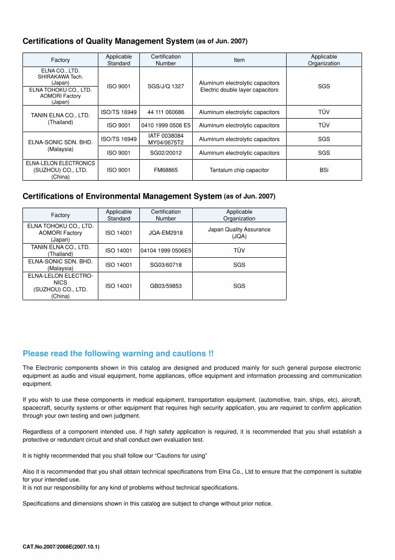
Certifications of Quality Management System (as of Jun. 2007)
FactoryApplicable Standard
Certification Number
ItemApplicable
OrganizationELNA CO., LTD.
SHIRAKAWA Tech. (Japan)
ISO 9001 SGS/J/Q 1327Aluminum electrolytic capacitors Electric double layer capacitors
SGSELNA TOHOKU CO., LTD.
AOMORI Factory (Japan)
TANIN ELNA CO., LTD. (Thailand)
ISO/TS 16949 44 111 060686 Aluminum electrolytic capacitors TÜV
ISO 9001 0410 1999 0506 E5 Aluminum electrolytic capacitors TÜV
ELNA-SONIC SDN. BHD. (Malaysia)
ISO/TS 16949IATF 0038084 MY04/0675T2
Aluminum electrolytic capacitors SGS
ISO 9001 SG02/20012 Aluminum electrolytic capacitors SGS
ELNA-LELON ELECTRONICS (SUZHOU) CO., LTD.
(China)ISO 9001 FM68865 Tantalum chip capacitor BSi
Certifications of Environmental Management System (as of Jun. 2007)
FactoryApplicable Standard
Certification Number
Applicable Organization
ELNA TOHOKU CO., LTD. AOMORI Factory
(Japan)ISO 14001 JQA-EM2918
Japan Quality Assurance (JQA)
TANIN ELNA CO., LTD. (Thailand)
ISO 14001 04104 1999 0506E5 TÜV
ELNA-SONIC SDN. BHD. (Malaysia)
ISO 14001 SG03/60718 SGS
ELNA-LELON ELECTRO-NICS
(SUZHOU) CO., LTD. (China)
ISO 14001 GB03/59853 SGS
®
169
1NOTEDesign, Specifications are subject to change without notice.Ask factory for technical specifications before purchase and/or use.
ENVIRONMENTAL (Green Cap®)
CAT.No.2006/2007E(2006.10.1)
“GREEN CAP”
Lineup of “GREEN CAP”
Category
Category
SMD(Chip type)
SMD(Chip type)
Small type
Largecapacitance
type
General type
For audio type
General type
For audio type
For audio type
General type
GREEN CAP
GREEN CAP
RV(ø8 to ø10), RV2, RV3, RV4, RV5, RVB,RVS, RVL, RVH, RVZ,RVK(ø8 to ø10), RVJ(ø8 to ø10)
PVO, PVH, RVO, RVW
RC3, R3S, RB3, RC2, R2S, RB2,RE3, R2B, RJ5, RJ4, RJ3, (RJJ), RJH, RJB, RJF, RK, RLB
RFS, ROS, ROA, ROB, R2O, R2A,R3A, RFO, RA2, RA3, RBD
SY1, SY2, SY3, SY4, SY5, SY6, SY7, SY8, SY9, SYF, SYL, SPY
LA5, LAG, LAH, LAT, LAV, LUH, LAX
LAO
RTJ, RTH, RTK, RV(ø12.5),RVJ(ø12.5), RVK(ø12.5), RYKThe above series correspond to ‘RoHSDirective’, but cannot be mounted on thecondition in page 28 and standard type.Please contact us for details.
We can respond in all series.For audio capacitors, tone quality may bechanged by changing the “GREEN CAP”.Please contact us for details.
We can respond in all series.
We can respond in all series.For audio capacitors, tone quality may bechanged by changing the “GREEN CAP”.Please contact us for details.
We can respond in all series.For audio capacitors, tone quality may bechanged by changing the “GREEN CAP”.Please contact us for details.
We can respond in all series.
We can respond in all series.
Notes
Notes
ELNA considers the environment, and the lineup “GREEN CAP” is not using hazardous substance.“GREEN CAP” is not using hazardous substance, for terminal plating and PVC sleeve.It is “GREEN CAP” when the note is not in the text.
“GREEN CAP” corresponds to environmental laws including ‘RoHS Directive’.
Aluminum electrolytic capacitors
Category
SMD(Chip type)
Lead type
GREEN CAP
DS, DSK(1.8mm Max.), DSK
DB, DBN, DBJ, DX, DXJ, DK, DH, DC, DCK, DZ, DZN, DP
We can respond in all series.
We can respond in all series.
Notes
Tantalum chip capacitors
Electric double layer capacitors
The prohibition substance isPb: lead, the Cr6+: hexavalent chromium, and Hg: mercury and Cd: cadmium andPBB: the polybrominated biphenyl and PBDE: the polybromo-diphenyl ether andPVC: Polyvinyl chloride.
This product doesn’t use the ozone-depleting substance provided for by the Montreal Protocol“Production process and production process of the material used” intentionally.
®
NOTEDesign, Specifications are subject to change without notice.Ask factory for technical specifications before purchase and/or use. 1 CAT.No.2007/2008E(2007.10.1)
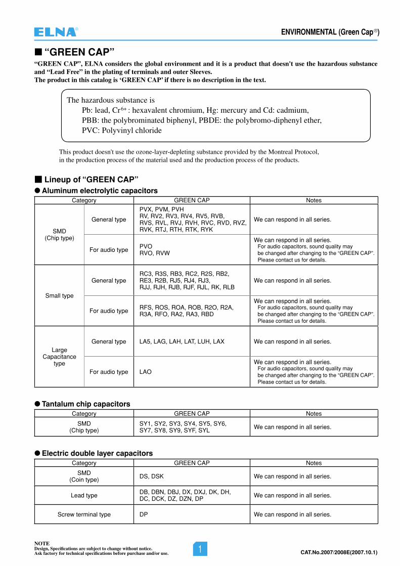
■ “GREEN CAP”“GREEN CAP”, ELNA considers the global environment and it is a product that doesn't use the hazardous substance and “Lead Free” in the plating of terminals and outer Sleeves. The product in this catalog is ‘GREEN CAP’ if there is no description in the text.
The hazardous substance isPb: lead, Cr6+ : hexavalent chromium, Hg: mercury and Cd: cadmium,PBB: the polybrominated biphenyl, PBDE: the polybromo-diphenyl ether,PVC: Polyvinyl chloride
This product doesn't use the ozone-layer-depleting substance provided by the Montreal Protocol,in the production process of the material used and the production process of the products.
■ Lineup of “GREEN CAP”●Aluminum electrolytic capacitors
Category GREEN CAP Notes
SMD(Chip type)
General type
PVX, PVM, PVHRV, RV2, RV3, RV4, RV5, RVB, RVS, RVL, RVJ, RVH, RVC, RVD, RVZ, RVK, RTJ, RTH, RTK, RYK
We can respond in all series.
For audio type PVORVO, RVW
We can respond in all series.For audio capacitors, sound quality maybe changed after changing to the “GREEN CAP”.Please contact us for details.
Small type
General typeRC3, R3S, RB3, RC2, R2S, RB2,RE3, R2B, RJ5, RJ4, RJ3,RJJ, RJH, RJB, RJF, RJL, RK, RLB
We can respond in all series.
For audio type RFS, ROS, ROA, ROB, R2O, R2A,R3A, RFO, RA2, RA3, RBD
We can respond in all series.For audio capacitors, sound quality maybe changed after changing to the “GREEN CAP”.Please contact us for details.
LargeCapacitance
type
General type LA5, LAG, LAH, LAT, LUH, LAX We can respond in all series.
For audio type LAO
We can respond in all series.For audio capacitors, sound quality maybe changed after changing to the “GREEN CAP”.Please contact us for details.
● Tantalum chip capacitorsCategory GREEN CAP Notes
SMD(Chip type)
SY1, SY2, SY3, SY4, SY5, SY6,SY7, SY8, SY9, SYF, SYL We can respond in all series.
● Electric double layer capacitorsCategory GREEN CAP Notes
SMD(Coin type) DS, DSK We can respond in all series.
Lead type DB, DBN, DBJ, DX, DXJ, DK, DH,DC, DCK, DZ, DZN, DP We can respond in all series.
Screw terminal type DP We can respond in all series.

2NOTEDesign, Specifications are subject to change without notice.Ask factory for technical specifications before purchase and/or use.
ENVIRONMENTAL (Green Cap®)
CAT.No.2006/2007E(2006.10.1)
• EU2002/95/EC RoHS Directive: The Restriction of the use of certain Hazardous Substances inelectrical and electronic equipment“Directive which places a ban on the use of hazardous substances” in relation to wasteelectrical and electronic equipment
Objective: To increase the protection of human health, as well as to ensure environmentalIy soundrecovery and disposal of waste eIectrical and electronic equipment.
Description: Lead, cadmium, mercury, hexavalent chromium, PBB (bromine additive), and PBDE(bromine additive) shall not be contained in the equipment to be supplied to theEuropean market from July 1, 2006.
• EU2000/53/EC End-of-Life Vehicle Directive (ELV Directive)Objective: To reduce, collect and reuse wastes from waste vehicles so as to promote recycling of those
parts for environmental protection.Description: In designing vehicles, efforts must be made to reduce the use of hazardous substances.
Vehicles must be so designed and manufactured that waste vehicles are easy to dismantle,reuse, recover, and recycle.In automobile manufacture, the degree of use of recycIed materiaIs shall be as high aspossible.Lead, cadmium, mercury, and hexavaIent chromium are in principle banned from use invehicles sold from July 2003.
• EU91/338/EEC Restriction of the Use of Cadmium in PlasticsObjective: To restrict the use of Cadmium, thereby reducing environmental pollution and improving
human health, whilst concurrently promoting research to find more environmentally friendlysubstitutes.
Description: Council directive 91/338/EEC, amending for the 10th time Directive 76/767/EEC, providesthat;-PIastics such as PVC or its copolymer, polyurethane, polyethylene, cellulose acetate,cellulose acetate butyrate and epoxy resin which are used in packaging materials, clothes,and insulation materials for electrical products shall not contain cadmium of 0.01% or more.In addition, the use of cadmium plating is banned.
• EU94/62/EC Packaging and Waste Packaging DirectiveObjective: To harmonize the policies among the EU countries so as to reduce environmental impacts
by recovering and reusing packaging materials and wastes from packaging materials.Description: This directive of 1994 first provided that the EU countries shaIl achieve the minimum target
of recovering and reuse of packaging materials such as plastic, metal, paper, board, andglass by June 30, 2001. However, the EU council has suggested a new target to beachieved by June 30, 2006, with a possible extension to 2008.The total content of lead, cadmium, mercury and hexavaIent chromium in the componentsof packaging materials shall be 100 ppm or less. This also applies to the “US restrictionof heavy metal content in packaging materiaIs”.
• EU2003/11/EC Amending for the 24th time Council Directive 76/769/EEC relating to restrictions onthe marketing and use of certain dangerous substances and preparations(pentabromodiphenyl ether, octabromodiphenyl ether)
“Green Cap” corresponds to environmental laws below.
®
NOTEDesign, Specifications are subject to change without notice.Ask factory for technical specifications before purchase and/or use.2CAT.No.2007/2008E(2007.10.1)
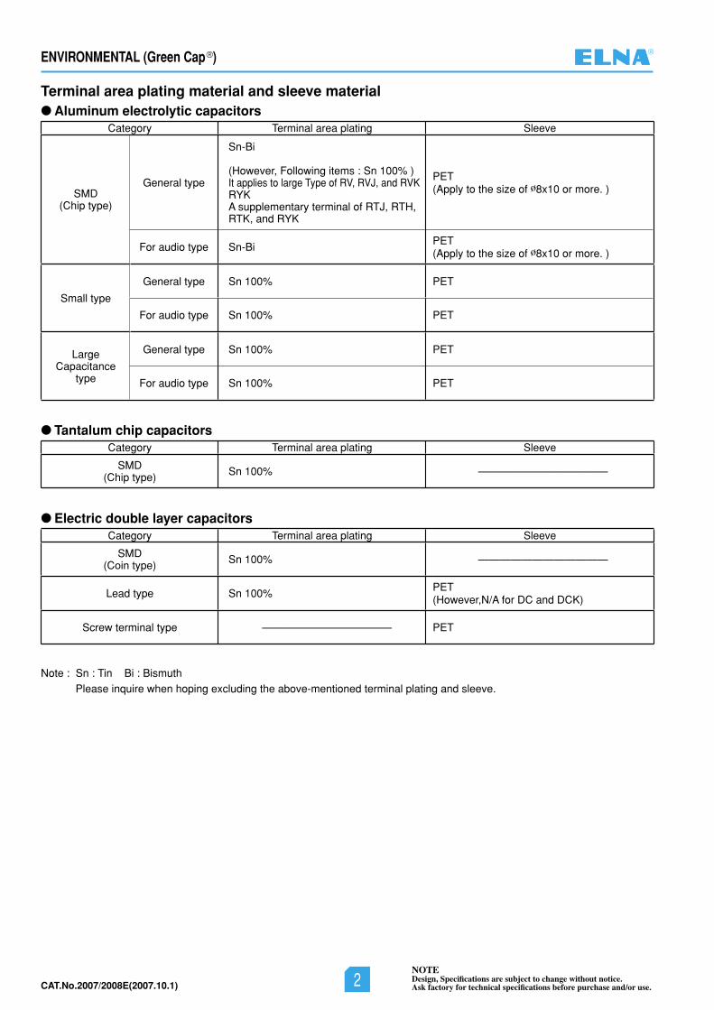
Terminal area plating material and sleeve material●Aluminum electrolytic capacitors
Category Terminal area plating Sleeve
SMD(Chip type)
General type
Sn-Bi
(However, Following items : Sn 100% )It applies to large Type of RV, RVJ, and RVKRYK A supplementary terminal of RTJ, RTH, RTK, and RYK
PET(Apply to the size of ø8x10 or more. )
For audio type Sn-BiPET(Apply to the size of ø8x10 or more. )
Small type
General type Sn 100% PET
For audio type Sn 100% PET
LargeCapacitance
type
General type Sn 100% PET
For audio type Sn 100% PET
● Tantalum chip capacitorsCategory Terminal area plating Sleeve
SMD(Chip type) Sn 100% ————————————
● Electric double layer capacitorsCategory Terminal area plating Sleeve
SMD(Coin type) Sn 100% ————————————
Lead type Sn 100%PET(However,N/A for DC and DCK)
Screw terminal type ———————————— PET
Note : Sn : Tin Bi : BismuthPlease inquire when hoping excluding the above-mentioned terminal plating and sleeve.
2NOTEDesign, Specifications are subject to change without notice.Ask factory for technical specifications before purchase and/or use.
ENVIRONMENTAL (Green Cap®)
CAT.No.2006/2007E(2006.10.1)
• EU2002/95/EC RoHS Directive: The Restriction of the use of certain Hazardous Substances inelectrical and electronic equipment“Directive which places a ban on the use of hazardous substances” in relation to wasteelectrical and electronic equipment
Objective: To increase the protection of human health, as well as to ensure environmentalIy soundrecovery and disposal of waste eIectrical and electronic equipment.
Description: Lead, cadmium, mercury, hexavalent chromium, PBB (bromine additive), and PBDE(bromine additive) shall not be contained in the equipment to be supplied to theEuropean market from July 1, 2006.
• EU2000/53/EC End-of-Life Vehicle Directive (ELV Directive)Objective: To reduce, collect and reuse wastes from waste vehicles so as to promote recycling of those
parts for environmental protection.Description: In designing vehicles, efforts must be made to reduce the use of hazardous substances.
Vehicles must be so designed and manufactured that waste vehicles are easy to dismantle,reuse, recover, and recycle.In automobile manufacture, the degree of use of recycIed materiaIs shall be as high aspossible.Lead, cadmium, mercury, and hexavaIent chromium are in principle banned from use invehicles sold from July 2003.
• EU91/338/EEC Restriction of the Use of Cadmium in PlasticsObjective: To restrict the use of Cadmium, thereby reducing environmental pollution and improving
human health, whilst concurrently promoting research to find more environmentally friendlysubstitutes.
Description: Council directive 91/338/EEC, amending for the 10th time Directive 76/767/EEC, providesthat;-PIastics such as PVC or its copolymer, polyurethane, polyethylene, cellulose acetate,cellulose acetate butyrate and epoxy resin which are used in packaging materials, clothes,and insulation materials for electrical products shall not contain cadmium of 0.01% or more.In addition, the use of cadmium plating is banned.
• EU94/62/EC Packaging and Waste Packaging DirectiveObjective: To harmonize the policies among the EU countries so as to reduce environmental impacts
by recovering and reusing packaging materials and wastes from packaging materials.Description: This directive of 1994 first provided that the EU countries shaIl achieve the minimum target
of recovering and reuse of packaging materials such as plastic, metal, paper, board, andglass by June 30, 2001. However, the EU council has suggested a new target to beachieved by June 30, 2006, with a possible extension to 2008.The total content of lead, cadmium, mercury and hexavaIent chromium in the componentsof packaging materials shall be 100 ppm or less. This also applies to the “US restrictionof heavy metal content in packaging materiaIs”.
• EU2003/11/EC Amending for the 24th time Council Directive 76/769/EEC relating to restrictions onthe marketing and use of certain dangerous substances and preparations(pentabromodiphenyl ether, octabromodiphenyl ether)
“Green Cap” corresponds to environmental laws below.
®
NOTEDesign, Specifications are subject to change without notice.Ask factory for technical specifications before purchase and/or use.2CAT.No.2007/2008E(2007.10.1)
Terminal area plating material and sleeve material●Aluminum electrolytic capacitors
Category Terminal area plating Sleeve
SMD(Chip type)
General type
Sn-Bi
(However, Following items : Sn 100% )It applies to large Type of RV, RVJ, and RVKRYK A supplementary terminal of RTJ, RTH, RTK, and RYK
PET(Apply to the size of ø8x10 or more. )
For audio type Sn-BiPET(Apply to the size of ø8x10 or more. )
Small type
General type Sn 100% PET
For audio type Sn 100% PET
LargeCapacitance
type
General type Sn 100% PET
For audio type Sn 100% PET
● Tantalum chip capacitorsCategory Terminal area plating Sleeve
SMD(Chip type) Sn 100% ————————————
● Electric double layer capacitorsCategory Terminal area plating Sleeve
SMD(Coin type) Sn 100% ————————————
Lead type Sn 100%PET(However,N/A for DC and DCK)
Screw terminal type ———————————— PET
Note : Sn : Tin Bi : BismuthPlease inquire when hoping excluding the above-mentioned terminal plating and sleeve.
CAT.No.2006/2007E(2006.10.1)3
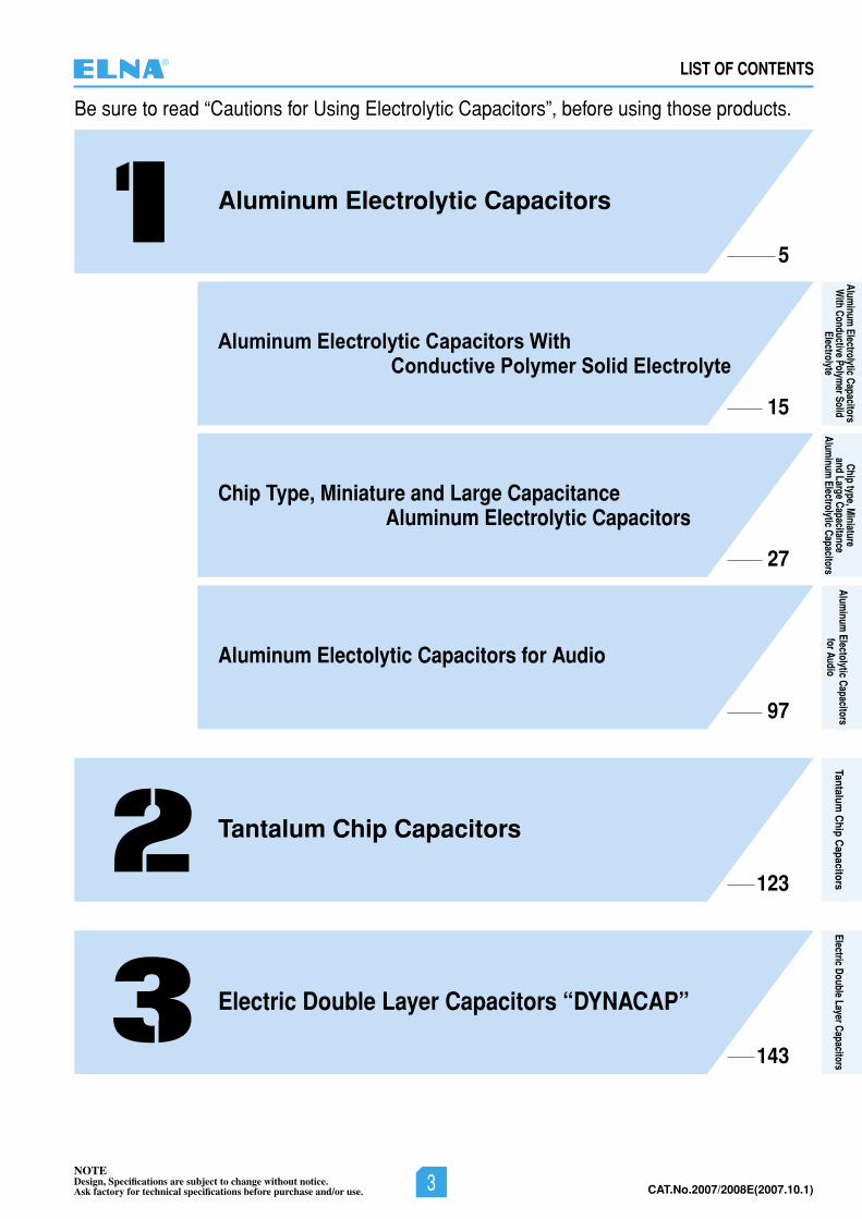
LIST OF CONTENTS
Be sure to read “Cautions for Using Electrolytic Capacitors”, before using those products.
Aluminum Electrolytic Capacitors
5
15
123
143
Aluminum Electrolytic Capacitors With Conductive Polymer Solid Electrolyte
27
Chip Type, Miniature and Large CapacitanceAluminum Electrolytic Capacitors
97
Aluminum Electolytic Capacitors for Audio
Electric Double Layer Capacitors “DYNACAP”
Tantalum Chip Capacitors
®
NOTEDesign, Specifications are subject to change without notice.Ask factory for technical specifications before purchase and/or use. 3 CAT.No.2007/2008E(2007.10.1)
Aluminum
Electrolytic Capacitors W
ith Conductive Polymer Solid
Electrolyte
Chip type, Miniature
and Large CapacitanceAlum
inum Electrolytic Capacitors
Aluminum
Electolytic Capacitorsfor Audio
Tantalum C
hip Capacitors
Electric Double Layer Capacitors
CAT.No.2006/2007E(2006.10.1) 4NOTEDesign, Specifications are subject to change without notice.Ask factory for technical specifications before purchase and/or use.
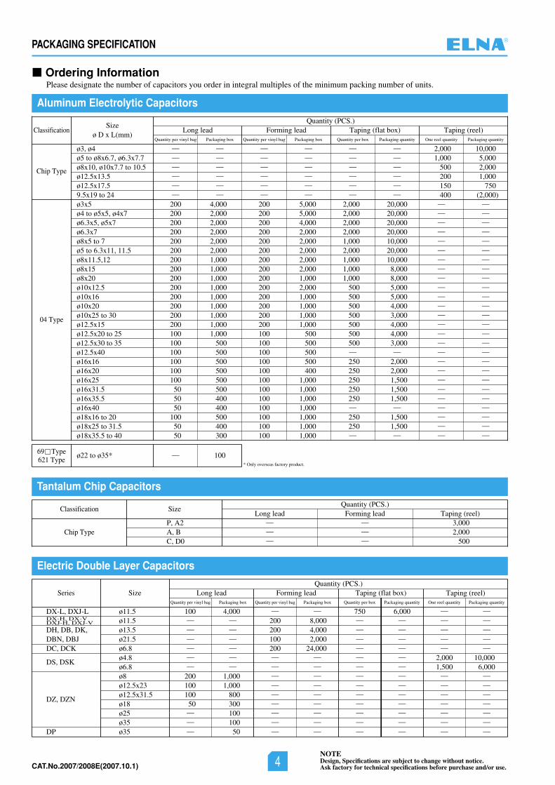
PACKAGING SPECIFICATION
Aluminum Electrolytic Capacitors
Tantalum Chip Capacitors
Electric Double Layer Capacitors
Ordering InformationPlease designate the number of capacitors you order in integral multiples of the minimum packing number of units.
ø3, ø4ø5 to ø8x6.7, ø6.3x7.7ø8x10, ø10x7.7 to 10.5ø12.5x13.5ø12.5x17.59.5x19 to 24ø3x5ø4 to ø5x5, ø4x7ø6.3x5, ø5x7ø6.3x7ø8x5 to 7ø5 to 6.3x11, 11.5ø8x11.5,12ø8x15ø8x20ø10x12.5ø10x16ø10x20ø10x25 to 30ø12.5x15ø12.5x20 to 25ø12.5x30 to 35ø12.5x40ø16x16ø16x20ø16x25ø16x31.5ø16x35.5ø16x40ø18x16 to 20ø18x25 to 31.5ø18x35.5 to 40
ø11.5ø11.5ø13.5ø21.5ø6.8øø
4.8
ø8ø12.5x23ø12.5x31.5ø18ø25ø35ø35
DX-L, DXJ-L
DH, DB, DK,DBN, DBJDC, DCK
DS, DSK
DZ, DZN
DP
DX-H, DX-VDXJ-H, DXJ-V
ø22 to ø35*
Quantity (PCS.)
Quantity (PCS.)
Classification
Classification
— — — — — — 2,000 10,000— — — — — — 1,000 5,000— — — — — — 500 2,000— — — — — — 200 1,000— — — — — — 150 750— — — — — — 400 (2,000)200 4,000 200 5,000 2,000 20,000 — —200 2,000 200 5,000 2,000 20,000 — —200 2,000 200 4,000 2,000 20,000 — —200 2,000 200 2,000 2,000 20,000 — —200 2,000 200 2,000 1,000 10,000 — —200 2,000 200 2,000 2,000 20,000 — —200 1,000 200 2,000 1,000 10,000 — —200 1,000 200 2,000 1,000 8,000 — —200 1,000 200 1,000 1,000 8,000 — —200 1,000 200 2,000 500 5,000 — —200 1,000 200 1,000 500 5,000 — —200 1,000 200 1,000 500 4,000 — —200 1,000 200 1,000 500 3,000 — —200 1,000 200 1,000 500 4,000 — —100 1,000 100 500 500 4,000 — —100 500 100 500 500 3,000 — —100 500 100 500 — — — —100 500 100 500 250 2,000 — —100 500 100 400 250 2,000 — —100 500 100 1,000 250 1,500 — —50 500 100 1,000 250 1,500 — —50 400 100 1,000 250 1,500 — —50 400 100 1,000 — — — —
100 500 100 1,000 250 1,500 — —50 400 100 1,000 250 1,500 — —50 300 100 1,000 — — — —
100 4,000 — — 750 6,000 — —— — 200 8,000 — — — —— — 200 4,000 — — — —— — 100 2,000 — — — —— — 200 24,000 — — — —— — — — — — 2,000 10,000
6.8 — — — — — — 1,500 6,000200 1,000 — — — — — —100 1,000 — — — — — —100 800 — — — — — —50 300 — — — — — —— 100 — — — — — —— 100 — — — — — —— 50 — — — — — —
— 100
Sizeø D x L(mm)
Series Size
Size
Taping (reel)
Taping (reel)
One reel quantity Packaging quantity
Taping (flat box)Quantity per box Packaging quantity
Forming lead
Forming lead
Quantity per vinyl bag Packaging box
Long lead
Long lead
Quantity per vinyl bag Packaging box
Quantity (PCS.)Taping (reel)
One reel quantity Packaging quantity
Taping (flat box)Quantity per box Packaging quantity
Forming leadQuantity per vinyl bag Packaging box
Long leadQuantity per vinyl bag Packaging box
Chip Type
Chip Type
69 Type621 Type
04 Type
* Only overseas factory product.
P, A2A, BC, D0
—— 3,000—— 2,000—— 500
®
NOTEDesign, Specifications are subject to change without notice.Ask factory for technical specifications before purchase and/or use.4CAT.No.2007/2008E(2007.10.1)
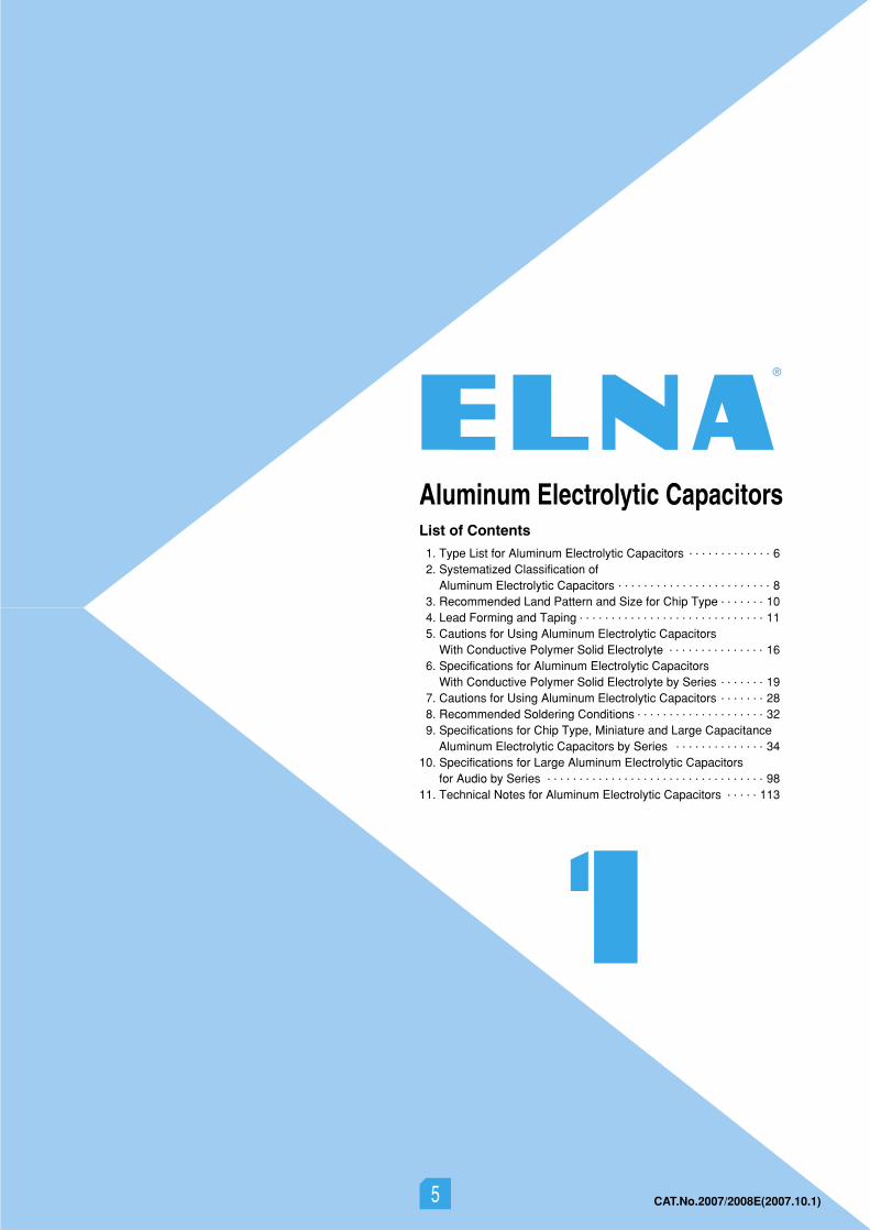
Aluminum Electrolytic CapacitorsList of Contents
1. Type List for Aluminum Electrolytic Capacitors • • • • • • • • • • • • • 62. Systematized Classification of
Aluminum Electrolytic Capacitors • • • • • • • • • • • • • • • • • • • • • • • • 83. Recommended Land Pattern and Size for Chip Type • • • • • • • 104. Lead Forming and Taping • • • • • • • • • • • • • • • • • • • • • • • • • • • • • 11
6. Specifications for Aluminum Electrolytic Capacitors With Conductive Polymer Solid Electrolyte by Series • • • • • • • 19
5. Cautions for Using Aluminum Electrolytic CapacitorsWith Conductive Polymer Solid Electrolyte • • • • • • • • • • • • • • • 16
7. Cautions for Using Aluminum Electrolytic Capacitors • • • • • • • 288. Recommended Soldering Conditions • • • • • • • • • • • • • • • • • • • • 329. Specifications for Chip Type, Miniature and Large Capacitance
Aluminum Electrolytic Capacitors by Series • • • • • • • • • • • • • • 3410. Specifications for Large Aluminum Electrolytic Capacitors
for Audio by Series • • • • • • • • • • • • • • • • • • • • • • • • • • • • • • • • • • 9811. Technical Notes for Aluminum Electrolytic Capacitors • • • • • 113
55 CAT.No.2007/2008E(2007.10.1)
6NOTEDesign, Specifications are subject to change without notice.Ask factory for technical specifications before purchase and/or use.
ALUMINUM ELECTROLYTIC CAPACITORS
CAT.No.2006/2007E(2006.10.1)
ALUMINUM ELECTROLYTIC CAPACITORS
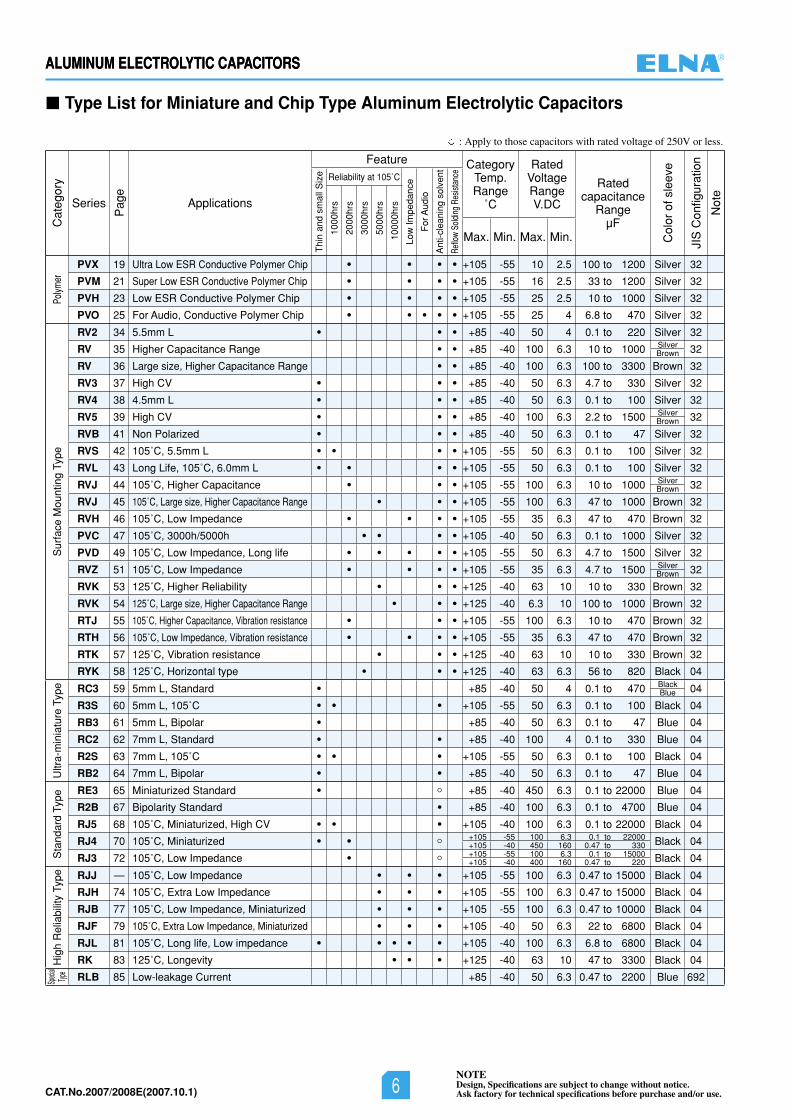
Type List for Miniature and Chip Type Aluminum Electrolytic Capacitors
Sur
face
Mou
ntin
g T
ype
Cat
egor
y
JIS
Con
figur
atio
n
Not
e
Thi
n an
d sm
all S
ize
1000
hrs
2000
hrs
3000
hrs
5000
hrs
1000
0hrs
Low
Impe
danc
e
For
Aud
io
Ant
i-cle
anin
g so
lven
t
Reflo
w So
ldin
g Re
sista
nce
Pag
e
Col
or o
f sle
eve
Sta
ndar
d T
ype
Ultr
a-m
inia
ture
Typ
eSp
ecial
Type
Pol
ymer
Larg
e C
apac
itanc
eT
ype
Series
PVO
PVH
RV2
RV
RV
RV3
RV4
RV5
RVB
RVS
RVL
RVJ
RVJ
RVH
RVZ
RVK
RVK
RTJ
RTH
RTK
RYK
RC3
R3S
RB3
RC2
R2S
RB2
RE3
R2B
RJ5
RJ4
RJ3
RJJ
RJH
RJB
RJF
RK
RLB
LA5
LH7
L3J
LAG
LAH
LAT
LAV
LUH
LAX
CategoryTemp.Range
˚C
RatedVoltageRangeV.DC
Ratedcapacitance
RangeµF
Max. Min. Max. Min.
Applications
Feature
Reliability at 105˚C
32
32
32
32
32
32
32
32
32
32
32
32
32
32
32
32
32
32
32
32
04
04
04
04
04
04
04
04
04
04
04
04
04
04
04
04
04
692
—
692
692
692
692
692
692
692
20
18
30
31
32
33
34
35
37
38
39
40
41
42
43
45
46
47
48
49
50
51
52
53
54
55
56
57
59
60
62
64
—
66
69
71
73
75
76
—
—
78
80
83
—
85
86
Hig
h R
elia
bilit
y Ty
pe
105 55 25 4 6.8 to 470 Silver
105 55 25 2.5 10 to 1000 Silver
85 40 50 4 0.1 to 220 Silver
85 40 100 6.3 10 to 1000
85 40 100 6.3 100 to 3300 Brown
85 40 50 6.3 4.7 to 330 Silver
85 40 50 6.3 0.1 to 100 Silver
85 40 100 6.3 2.2 to 1500
85 40 50 6.3 0.1 to 47 Silver
105 55 50 6.3 0.1 to 100 Silver
105 55 50 6.3 0.1 to 100 Silver
105 55 100 6.3 10 to 1000
105 55 100 6.3 47 to 1000 Brown
105 55 35 6.3 47 to 470 Brown
105 55 35 6.3 4.7 to 1500
125 40 63 10 10 to 330 Brown
125 40 6.3 10 100 to 1000 Brown
105 55 100 6.3 10 to 470 Brown
105 55 35 6.3 47 to 470 Brown
125 40 63 10 10 to 330 Brown
125 40 63 6.3 56 to 820 Black
85 40 50 4 0.1 to 470
105 55 50 6.3 0.1 to 100 Black
85 40 50 6.3 0.1 to 47 Blue
85 40 100 4 0.1 to 330 Blue
105 55 50 6.3 0.1 to 100 Black
85 40 50 6.3 0.1 to 47 Blue
85 40 450 6.3 0.1 to 22000 Blue
85 40 100 6.3 0.1 to 4700 Blue
105 40 100 6.3 0.1 to 22000 Black
Black
Black
105 55 100 6.3 0.47 to 15000 Black
105 55 100 6.3 0.47 to 15000 Black
105 55 100 6.3 0.47 to 10000 Black
105 40 50 6.3 22 to 6800 Black
125 40 63 10 47 to 3300 Black
85 40 50 6.3 0.47 to 2200 Blue
Black
85 40 200 16 470 to 15000 Black
Black
105 25 400 160 56 to 1800 Black
105 25 450 16 56 to 47000 Black
105 25 400 160 82 to 2700 Black
105 25 250 — 82 to 1000 Black
105 25 400 200 68 to 1500 Black
105 25 400 160 56 to 1800 Black
SilverBrown
SilverBrown
1, 2
2
2
2
1, 2
2
2
1, 2
2
1
SilverBrown
SilverBrown
105 55 100 6.3 0.1 to 22000105 40 450 160 0.47 to 330105 55 100 6.3 0.1 to 15000105 40 400 160 0.47 to 220
85 40 400 10 56 to 8200085 25 450 — 47 to 470
105 40 200 10 150 to 22000105 25 400 250 39 to 820
For Audio, Conductive Polymer Chip
For Audio, Low ESR Conductive Polymer Chip
5.5mm L
Higher Capacitance Range
Large size, Higher Capacitance Range
High CV
4.5mm L
High CV
Non Polarized
105˚C, 5.5mm L
Long Life, 105˚C, 6.0mm L
105˚C, Higher Capacitance
105˚C, Large size, Higher Capacitance Range
105˚C, Low Impedance
105˚C, Low Impedance
125˚C, Higher Reliability
125˚C, Large size, Higher Capacitance Range
105˚C, Higher Capacitance, Vibration resistance
105˚C, Low Impedance, Vibration resistance
125˚C, Vibration resistance
125˚C, Horizontal type
5mm L, Standard
5mm L, 105˚C
5mm L, Bipolar
7mm L, Standard
7mm L, 105˚C
7mm L, Bipolar
Miniaturized Standard
Bipolarity Standard
105˚C, Miniaturized, High CV
105˚C, Miniaturized
105˚C, Low Impedance
105˚C, Low Impedance
105˚C, Extra Low Impedance
105˚C, Low Impedance, Miniaturized
105˚C, Extra Low Impedance, Miniaturized
125˚C, Longevity
Low-leakage Current
PCB Terminal,Snap-In Type
105˚C,Standard
High-Reliability,High Ripple
High-Reliability,Ultra-Miniaturized
Super Miniaturization,High Ripple
105˚C,Compatible with VDE
105˚C,Durable against Over Voltage
105˚C,Ultra-Longevity
: Apply to those capacitors with rated voltage of 250V or less.
BlackBlue
®
NOTEDesign, Specifications are subject to change without notice.Ask factory for technical specifications before purchase and/or use.6CAT.No.2007/2008E(2007.10.1)
Cat
egor
y
Series
Pag
e
Applications
Feature CategoryTemp. Range
˚C
RatedVoltage RangeV.DC
Ratedcapacitance
RangeµF
Col
or o
f sle
eve
JIS
Con
figur
atio
n
Not
e
Thi
n an
d sm
all S
ize Reliability at 105˚C
Low
Impe
danc
e
For
Aud
io
Ant
i-cle
anin
g so
lven
t
Reflo
w So
ldin
g Re
sista
nce
1000
hrs
2000
hrs
3000
hrs
5000
hrs
1000
0hrs
Max. Min. Max. Min.
Polym
er
PVX 19 Ultra Low ESR Conductive Polymer Chip ● ● ● ● +105 -55 10 2.5 100 to 1200 Silver 32
PVM 21 Super Low ESR Conductive Polymer Chip ● ● ● ● +105 -55 16 2.5 33 to 1200 Silver 32
PVH 23 Low ESR Conductive Polymer Chip ● ● ● ● +105 -55 25 2.5 10 to 1000 Silver 32
PVO 25 For Audio, Conductive Polymer Chip ● ● ● ● ● +105 -55 25 4 6.8 to 470 Silver 32
Sur
face
Mou
ntin
g Ty
pe
RV2 34 5.5mm L ● ● ● +85 -40 50 4 0.1 to 220 Silver 32
RV 35 Higher Capacitance Range ● ● +85 -40 100 6.3 10 to 1000 Silver 32Brown
RV 36 Large size, Higher Capacitance Range ● ● +85 -40 100 6.3 100 to 3300 Brown 32
RV3 37 High CV ● ● ● +85 -40 50 6.3 4.7 to 330 Silver 32
RV4 38 4.5mm L ● ● ● +85 -40 50 6.3 0.1 to 100 Silver 32
RV5 39 High CV ● ● ● +85 -40 100 6.3 2.2 to 1500 Silver 32Brown
RVB 41 Non Polarized ● ● ● +85 -40 50 6.3 0.1 to 47 Silver 32
RVS 42 105˚C, 5.5mm L ● ● ● ● +105 -55 50 6.3 0.1 to 100 Silver 32
RVL 43 Long Life, 105˚C, 6.0mm L ● ● ● ● +105 -55 50 6.3 0.1 to 100 Silver 32
RVJ 44 105˚C, Higher Capacitance ● ● ● +105 -55 100 6.3 10 to 1000 Silver 32Brown
RVJ 45 105˚C, Large size, Higher Capacitance Range ● ● ● +105 -55 100 6.3 47 to 1000 Brown 32
RVH 46 105˚C, Low Impedance ● ● ● ● +105 -55 35 6.3 47 to 470 Brown 32
PVC 47 105˚C, 3000h/5000h ● ● ● ● +105 -40 50 6.3 0.1 to 1000 Silver 32
PVD 49 105˚C, Low Impedance, Long life ● ● ● ● ● +105 -55 50 6.3 4.7 to 1500 Silver 32
RVZ 51 105˚C, Low Impedance ● ● ● ● +105 -55 35 6.3 4.7 to 1500 Silver 32Brown
RVK 53 125˚C, Higher Reliability ● ● ● +125 -40 63 10 10 to 330 Brown 32
RVK 54 125˚C, Large size, Higher Capacitance Range ● ● ● +125 -40 6.3 10 100 to 1000 Brown 32
RTJ 55 105˚C, Higher Capacitance, Vibration resistance ● ● ● +105 -55 100 6.3 10 to 470 Brown 32
RTH 56 105˚C, Low Impedance, Vibration resistance ● ● ● ● +105 -55 35 6.3 47 to 470 Brown 32
RTK 57 125˚C, Vibration resistance ● ● ● +125 -40 63 10 10 to 330 Brown 32
RYK 58 125˚C, Horizontal type ● ● ● +125 -40 63 6.3 56 to 820 Black 04
Ultr
a-m
inia
ture
Typ
e RC3 59 5mm L, Standard ● +85 -40 50 4 0.1 to 470 Black 04Blue
R3S 60 5mm L, 105˚C ● ● ● +105 -55 50 6.3 0.1 to 100 Black 04
RB3 61 5mm L, Bipolar ● +85 -40 50 6.3 0.1 to 47 Blue 04
RC2 62 7mm L, Standard ● ● +85 -40 100 4 0.1 to 330 Blue 04
R2S 63 7mm L, 105˚C ● ● ● +105 -55 50 6.3 0.1 to 100 Black 04
RB2 64 7mm L, Bipolar ● ● +85 -40 50 6.3 0.1 to 47 Blue 04
Sta
ndar
d Ty
pe
RE3 65 Miniaturized Standard ● ○ +85 -40 450 6.3 0.1 to 22000 Blue 04
R2B 67 Bipolarity Standard ● +85 -40 100 6.3 0.1 to 4700 Blue 04
RJ5 68 105˚C, Miniaturized, High CV ● ● ● +105 -40 100 6.3 0.1 to 22000 Black 04
RJ4 70 105˚C, Miniaturized ● ● ○ +105 -55 100 6.3 0.1 to 22000 Black 04+105 -40 450 160 0.47 to 330
RJ3 72 105˚C, Low Impedance ● ○ +105 -55 100 6.3 0.1 to 15000 Black 04+105 -40 400 160 0.47 to 220
Hig
h R
elia
bilit
y Ty
pe RJJ — 105˚C, Low Impedance ● ● ● +105 -55 100 6.3 0.47 to 15000 Black 04
RJH 74 105˚C, Extra Low Impedance ● ● ● +105 -55 100 6.3 0.47 to 15000 Black 04
RJB 77 105˚C, Low Impedance, Miniaturized ● ● ● +105 -55 100 6.3 0.47 to 10000 Black 04
RJF 79 105˚C, Extra Low Impedance, Miniaturized ● ● ● +105 -40 50 6.3 22 to 6800 Black 04
RJL 81 105˚C, Long life, Low impedance ● ● ● ● ● +105 -40 100 6.3 6.8 to 6800 Black 04
RK 83 125˚C, Longevity ● ● ● +125 -40 63 10 47 to 3300 Black 04
Speci
alTyp
e
RLB 85 Low-leakage Current +85 -40 50 6.3 0.47 to 2200 Blue 692
ALUMINUM ELECTROLYTIC CAPACITORS
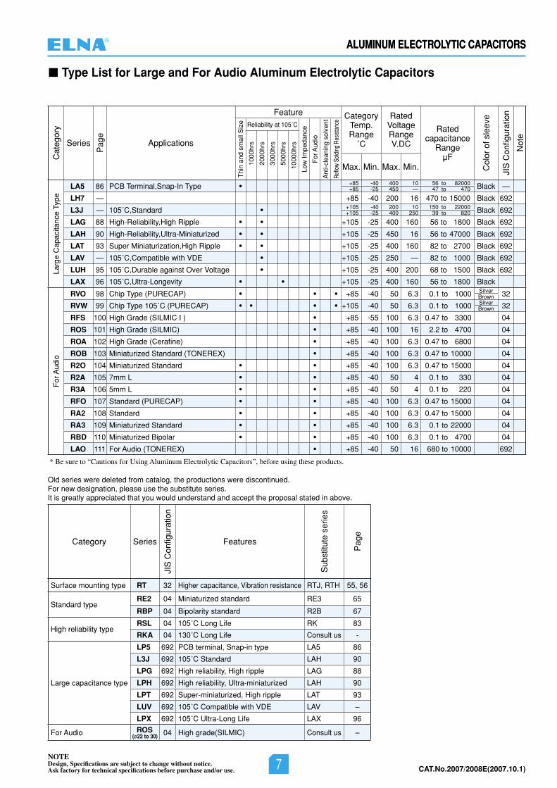
Type List for Large and For Audio Aluminum Electrolytic Capacitors
For
Aud
io
88
89
90
91
92
93
94
95
96
97
98
99
100
101
85 40 50 6.3 0.1 to 1000
105 40 50 6.3 0.1 to 1000
85 55 100 6.3 0.47 to 3300
85 40 100 16 2.2 to 4700
85 40 100 6.3 0.47 to 6800
85 40 100 6.3 0.47 to 10000
85 40 100 6.3 0.47 to 15000
85 40 50 4 0.1 to 330
85 40 50 4 0.1 to 220
85 40 100 6.3 0.47 to 15000
85 40 100 6.3 0.47 to 15000
85 40 100 6.3 0.1 to 22000
85 40 100 6.3 0.1 to 4700
85 40 100 16 680 to 10000 2
SilverBrownSilverBrown
ALUMINUM ELECTROLYTIC CAPACITORS
Be sure to “Cautions for Using Aluminum Electrolytic Capacitors”, before using these products.
1 Please refer to our web-page about RJJ series, LH7 series, L3J series and LAV series. (web-address http://www.elna.co.jp/)
2 There are overseas factory product only on above table.
Chip Type (PURECAP)
Chip Type 105˚C (PURECAP)
High Grade (SILMIC II )
High Grade (SILMIC)
High Grade (Cerafine)
Miniaturized Standard (TONEREX)
Miniaturized Standard
7mm L
5mm L
Standard (PURECAP)
Standard
Miniaturized Standard
Miniaturized Bipolar
For Audio(TONEREX)
32
32
04
04
04
04
04
04
04
04
04
04
04
692
RVO
RVW
RFS
ROS
ROA
ROB
R2O
R2A
R3A
RFO
RA2
RA3
RBD
LAO
Cat
egor
y
JIS
Con
figur
atio
n
Not
e
Thi
n an
d sm
all S
ize
1000
hrs
2000
hrs
3000
hrs
5000
hrs
1000
0hrs
Low
Impe
danc
e
For
Aud
io
Ant
i-cle
anin
g so
lven
t
Reflo
w So
ldin
g Re
sista
nce
Pag
e
Col
or o
f sle
eve
Series
CategoryTemp.Range
˚C
RatedVoltageRangeV.DC
Ratedcapacitance
RangeµF
Max. Min. Max. Min.
Applications
Feature
Reliability at 105˚C
®
NOTEDesign, Specifications are subject to change without notice.Ask factory for technical specifications before purchase and/or use. 7 CAT.No.2007/2008E(2007.10.1)
Cat
egor
y
Series
Pag
e
Applications
Feature CategoryTemp. Range
˚C
RatedVoltage RangeV.DC
Ratedcapacitance
RangeµF
Col
or o
f sle
eve
JIS
Con
figur
atio
n
Not
e
Thi
n an
d sm
all S
ize Reliability at 105˚C
Low
Impe
danc
e
For
Aud
io
Ant
i-cle
anin
g so
lven
t
Reflo
w So
ldin
g Re
sista
nce
1000
hrs
2000
hrs
3000
hrs
5000
hrs
1000
0hrs
Max. Min. Max. Min.
Larg
e C
apac
itanc
e Ty
pe
LA5 86 PCB Terminal,Snap-In Type ● +85 -40 400 10 56 to 82000 Black —+85 -25 450 — 47 to 470
LH7 — +85 -40 200 16 470 to 15000 Black 692
L3J — 105˚C,Standard ● +105 -40 200 10 150 to 22000 Black 692+105 -25 400 250 39 to 820
LAG 88 High-Reliability,High Ripple ● ● +105 -25 400 160 56 to 1800 Black 692
LAH 90 High-Reliability,Ultra-Miniaturized ● ● +105 -25 450 16 56 to 47000 Black 692
LAT 93 Super Miniaturization,High Ripple ● ● +105 -25 400 160 82 to 2700 Black 692
LAV — 105˚C,Compatible with VDE ● +105 -25 250 — 82 to 1000 Black 692
LUH 95 105˚C,Durable against Over Voltage ● +105 -25 400 200 68 to 1500 Black 692
LAX 96 105˚C,Ultra-Longevity ● ● +105 -25 400 160 56 to 1800 Black
For
Aud
io
RVO 98 Chip Type (PURECAP) ● ● ● +85 -40 50 6.3 0.1 to 1000 Silver 32Brown
RVW 99 Chip Type 105˚C (PURECAP) ● ● ● ● +105 -40 50 6.3 0.1 to 1000 Silver 32Brown
RFS 100 High Grade (SILMIC I ) ● +85 -55 100 6.3 0.47 to 3300 04
ROS 101 High Grade (SILMIC) ● +85 -40 100 16 2.2 to 4700 04
ROA 102 High Grade (Cerafine) ● +85 -40 100 6.3 0.47 to 6800 04
ROB 103 Miniaturized Standard (TONEREX) ● +85 -40 100 6.3 0.47 to 10000 04
R2O 104 Miniaturized Standard ● ● +85 -40 100 6.3 0.47 to 15000 04
R2A 105 7mm L ● ● +85 -40 50 4 0.1 to 330 04
R3A 106 5mm L ● ● +85 -40 50 4 0.1 to 220 04
RFO 107 Standard (PURECAP) ● ● +85 -40 100 6.3 0.47 to 15000 04
RA2 108 Standard ● ● +85 -40 100 6.3 0.47 to 15000 04
RA3 109 Miniaturized Standard ● ● +85 -40 100 6.3 0.1 to 22000 04
RBD 110 Miniaturized Bipolar ● ● +85 -40 100 6.3 0.1 to 4700 04
LAO 111 For Audio (TONEREX) ● +85 -40 50 16 680 to 10000 692
* Be sure to “Cautions for Using Aluminum Electrolytic Capacitors”, before using these products.
Old series were deleted from catalog, the productions were discontinued. For new designation, please use the substitute series. It is greatly appreciated that you would understand and accept the proposal stated in above.
Category Series
JIS
Con
figur
atio
n
Features
Sub
stitu
te s
erie
s
Pag
e
Surface mounting type RT 32 Higher capacitance, Vibration resistance RTJ, RTH 55, 56
Standard typeRE2 04 Miniaturized standard RE3 65
RBP 04 Bipolarity standard R2B 67
High reliability typeRSL 04 105˚C Long Life RK 83
RKA 04 130˚C Long Life Consult us -
Large capacitance type
LP5 692 PCB terminal, Snap-in type LA5 86
L3J 692 105˚C Standard LAH 90
LPG 692 High reliability, High ripple LAG 88
LPH 692 High reliability, Ultra-miniaturized LAH 90
LPT 692 Super-miniaturized, High ripple LAT 93
LUV 692 105˚C Compatible with VDE LAV –
LPX 692 105˚C Ultra-Long Life LAX 96
For Audio ROS(ø22 to 30) 04 High grade(SILMIC) Consult us –
8NOTEDesign, Specifications are subject to change without notice.Ask factory for technical specifications before purchase and/or use.
ALUMINUM ELECTROLYTIC CAPACITORS
CAT.No.2006/2007E(2006.10.1)
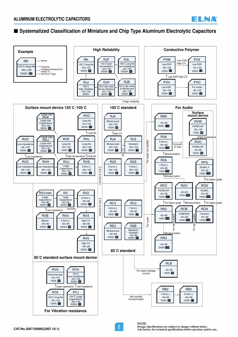
Systematized Classification of Miniature and Chip Type Aluminum Electrolytic Capacitors
High Reliability Conductive Polymer
RK125˚C long life
-40/+1255000h 83
RJF105˚C Super
low impedance-40/+1055000h 79
RJB105˚C high reliabi-
lity Miniaturized-55/+1055000h 77
RJJ105˚C
high reliability-55/+105
5000h
RJH105˚C high reliabi-lity low impedance
-55/+1055000h 74
RJL105˚C Long lifelow impedance
-40/+10510000h 81
Example
Series
FeaturesCategory temperaturerange(˚C)Life time, Page
RK125˚C long life
-40/+1255000h 83
105˚C standard
85˚C standard
RBD
-40/+852000h 110
106
R3A5.0mm L-40/+85
1000h
R2A7.0mm L-40/+85
1000h
RFOPURECAP
-40/+851000h
ytilalopnon
oiduaro
Fo idua
roF
For Audio
RV25.5mm L-40/+85
2000h 34
RVBBipolar-40/+85
2000h 41
RV44.5mm L-40/+85
2000h 38
RV3High CV-40/+85
2000h 37
RVKLong life-40/+1251250h 58
RVLLong life-55/+1052000h 43
RVZLow impedance
-55/+1052000h 51
RVDLow impedance
-55/+1055000h 49
RVHLow impedance
-55/+1052000h 46
RVS5.5mm L-55/+1051000h 42
Surface mount device 125˚C /105˚C
RJ4Miniaturized
-55/+1052000h 70
RJ5Miniaturized
-55/+1051000h 68
RJ3Standard-55/+1052000h 72
R3S5.0mm L-55/+1051000h 60
R2S7.0mm L-55/+1051000h 63
RC35.0mm L-40/+85
1000h 59
RC27.0mm L-40/+85
1000h 62
RE3Miniaturized
-40/+852000h 65
ROBTONEREX
-40/+851000h
ROACerafine-40/+85
1000h
For h
ighe
r gra
de
For h
ighe
r gra
de
For higher grade
Miniaturization
Miniaturization
Miniaturization
ROSSILMIC-40/+85
1000h
RFS
SILMIC II-40/+85
1000h
Surfacemount device
RVOPURECAP
-40/+852000h 98
RVWPURECAP
-55/+1051000h 99
Conventto chip
85˚C standard surface mount device
For Vibration resistance
RTH105˚C
Low impedance-55/+1052000h 56
RTK125˚C long life
-40/+1251250h 57
RTJ105˚C LargeCapacitance
-55/+1052000h 55
RVLarge
Capacitance-40/+85
2000h 35
RVJLarge
Capacitance-55/+1052000h 44
RV(Large)
LargeCapacitance
-40/+852000h 36
Large sizeRVJ
Large sizeCapacitance
-55/+1055000h 45
Large sizeRVK
Large sizeCapacitance
-40/+1255000h 54
High reliability
RA3
-40/+852000h
R2O
-40/+851000h
RA2
-40/+851000h
RLB
-40/+851000h 85
For lower leakagecurrent
RB27.0mm L-40/+85
1000h 64
Non polalityminiaturization
RB35.0mm L-40/+85
1000h 61
Con
vert
to c
hip
R2BBipolaritystandard-40/+85
2000h 67
Con
vert
to c
hip
Hig
h C
V
Low profile
High temperature Long life
RVCLong life-40/+1055000h 47
Long life
Low impedance
RV5High CV-40/+85
2000h 39
For higher grade
For higher grade
Large capacitance
RYKHorizontal type
-40/+1251000h 58
High CV
Miniaturization
High temperature
PVXLow ESR
-55/+105
2000h 19
PVOFor Audio-55/+105
2000h 25
9
Low impedance
Low impedance
PVMLow ESR
-55/+105
2000h 21
PVHLow ESR-55/+105
2000h 23
Low ESR High CV
Low ESRHigh CV
105100
107104 101
108103 102
109
®
NOTEDesign, Specifications are subject to change without notice.Ask factory for technical specifications before purchase and/or use.8CAT.No.2007/2008E(2007.10.1)
9NOTEDesign, Specifications are subject to change without notice.Ask factory for technical specifications before purchase and/or use.
ALUMINUM ELECTROLYTIC CAPACITORS
CAT.No.2006/2007E(2006.10.1)
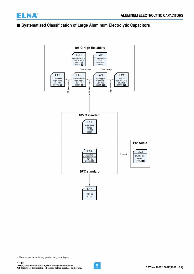
Systematized Classification of Large Aluminum Electrolytic Capacitors
105˚C High Reliability
Min
iatu
rizat
ion
Min
iatu
rizat
ion
Hig
h re
liabi
lity
LUHDurable against
over voltage-25/+1052000h 95
LAVCompatible with
VDE-25/+105
2000h
LAGHigh rippleStandard-25/+1052000h 88
LAHMiniaturization
High ripple-25/+1052000h 90
LATUltra mini
High ripple-25/+1052000h 93
LAXLong life
High reliability-25/+1055000h 96
Over voltageOver voltage
105˚C standard
85˚C standard
L3JWide temp.
range-40/+105
2000h
LAO(TONEREX)
-40/+851000h 112
LA5Standard
(Miniaturization)-40/+85
2000h 86
LH7
-40/+851000h
For audio
For Audio
There are overseas factory product only on this page.
®
NOTEDesign, Specifications are subject to change without notice.Ask factory for technical specifications before purchase and/or use. 9 CAT.No.2007/2008E(2007.10.1)
CAT.No.2006/2007E(2006.10.1) 10NOTEDesign, Specifications are subject to change without notice.Ask factory for technical specifications before purchase and/or use.
CHIP TYPE ALUMINUM ELECTROLYTIC CAPACITORS
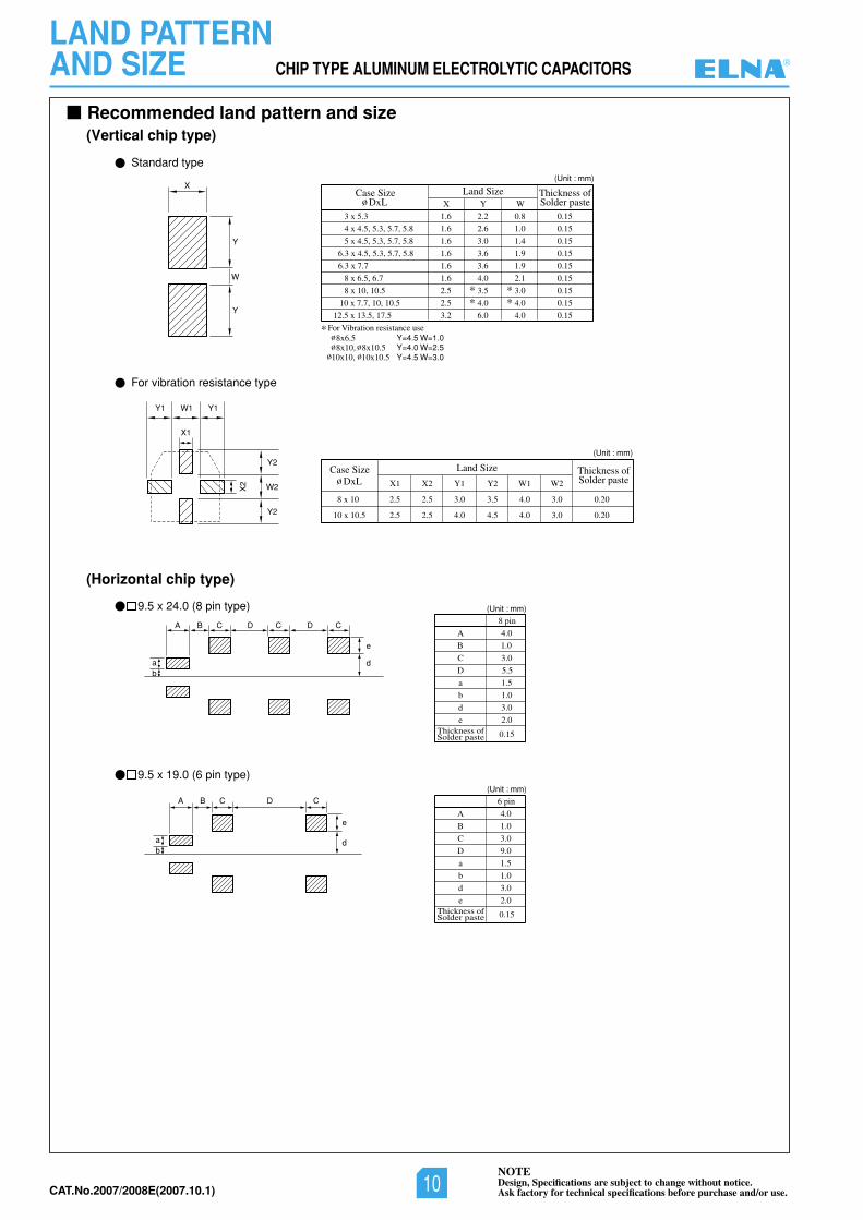
LAND PATTERNAND SIZE
Recommended land pattern and size
Solder paste
Y
Y=4.0 W=2.5Y=4.5 W=3.0
X
Y
W
3 x 5.3
For Vibration resistance use
1.6 2.2
3.0
4.0
4.0
6.0
3.6
3.5
2.6
3.6
0.8
X Y W
Land Size
W2
3.0
3.0
0.20
0.20
W1
4.0
4.0
Y2
3.5
4.5
Y1
3.0
4.0
X2
2.5
2.5
2.5
2.5
X1
8 x 10
10 x 10.5
Case Size
Thickness of
Solder pasteThickness of
Solder pasteThickness of
Land Size
1.0
1.4
1.9
1.9
2.1
3.0
4.0
4.0
0.15
0.15
0.15
0.15
0.15
0.15
0.15
0.15
0.15
4 x 4.5, 5.3, 5.7, 5.8 1.6
5 x 4.5, 5.3, 5.7, 5.8 1.6
6.3 x 4.5, 5.3, 5.7, 5.8
6.3 x 7.7
1.6
1.6
8 x 6.5, 6.7 1.6
8 x 10, 10.5 2.5
2.5
3.2
10 x 7.7, 10, 10.5
8x10, 8x10.510x10, 10x10.5
12.5 x 13.5, 17.5
Y2
W2
Y2
X2
X1
Y1 Y1W1
Standard type
9.5 x 19.0 (6 pin type)
For vibration resistance type
ab
A D C
e
d
C
ab
DA B C
D
C
B C
e
d
Case SizeDxL
A 4.0
8 pin
C 3.0
D
a
5.5
1.5
b 1.0
d 3.0
2.0
0.15
Solder pasteThickness of 0.15
e
DxL
9.5 x 24.0 (8 pin type) (Unit : mm)
A 4.0
3.0
1.0
2.0
1.5
3.0
1.0
9.0
6 pin
B
C
D
a
b
d
e
(Unit : mm)
(Unit : mm)
(Unit : mm)
(Vertical chip type)
(Horizontal chip type)
Y=4.5 W=1.08x6.5
B 1.0
®
NOTEDesign, Specifications are subject to change without notice.Ask factory for technical specifications before purchase and/or use.10CAT.No.2007/2008E(2007.10.1)
CAT.No.2006/2007E(2006.10.1)11NOTEDesign, Specifications are subject to change without notice.Ask factory for technical specifications before purchase and/or use.
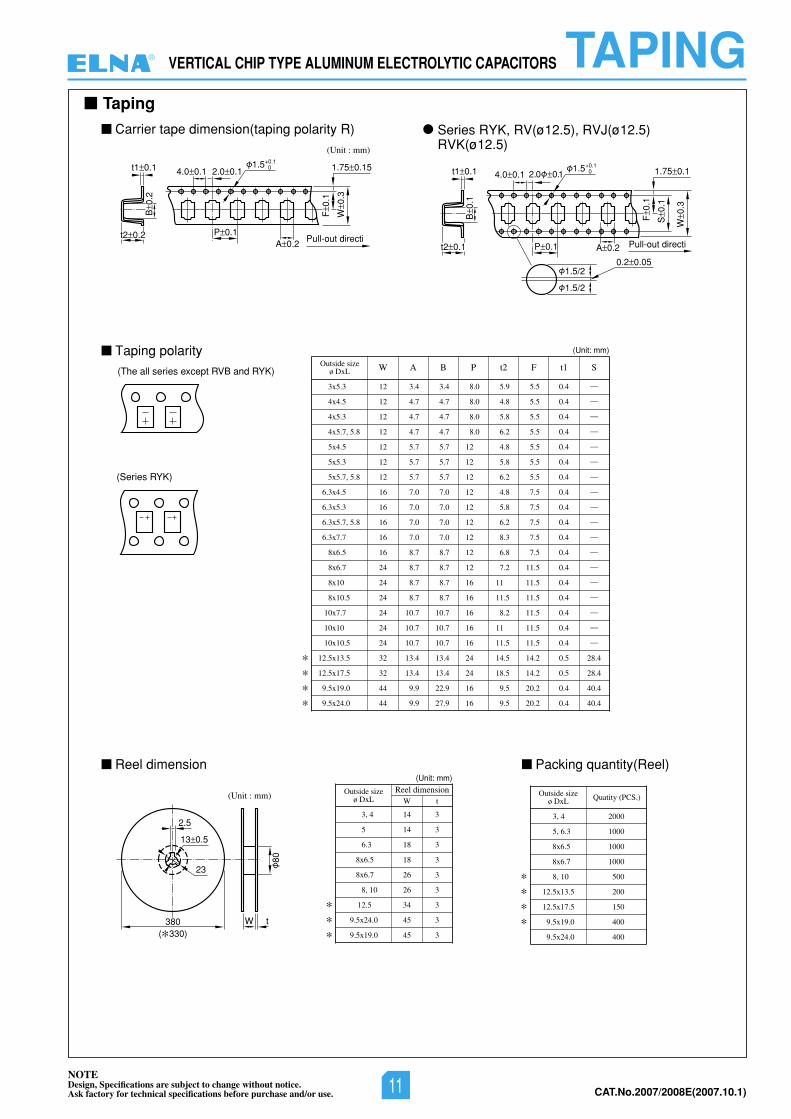
VERTICAL CHIP TYPE ALUMINUM ELECTROLYTIC CAPACITORS TAPING
(Unit : mm)
2.0 0.1
P 0.1
4.0 0.11.5+0.1
0
A 0.2
1.75 0.15
Pull-out directit2 0.2
F0.
1
W0.
3
t1 0.1
B0.
2
2.0 0.1
P 0.1
4.0 0.11.5+0.1
0
A 0.2
0.2 0.05
1.75 0.1
Pull-out directit2 0.1
F0.
1
S0.
1
W0.
3
t1 0.1
B0.
1
1.5/2
1.5/2
(The all series except RVB and RYK)
(Series RYK)
(Unit : mm)
2.5
13 0.5
23
380( 330)
80
W t
3x5.3
4x4.5
4x5.3
4x5.7, 5.8
5x4.5
5x5.3
5x5.7, 5.8
6.3x4.5
6.3x5.3
6.3x5.7, 5.8
6.3x7.7
8x6.5
8x6.7
8x10
8x10.5
10x7.7
10x10
10x10.5
12.5x13.5
12.5x17.5
9.5x19.0
9.5x24.0
12 3.4 3.4 8.0 5.9 5.5 0.4 —
12 4.7 4.7 8.0 4.8 5.5 0.4 —
12 4.7 4.7 8.0 5.8 5.5 0.4 —
12 4.7 4.7 8.0 6.2 5.5 0.4 —
12 5.7 5.7 12 4.8 5.5 0.4 —
12 5.7 5.7 12 5.8 5.5 0.4 —
12 5.7 5.7 12 6.2 5.5 0.4 —
16 7.0 7.0 12 4.8 7.5 0.4 —
16 7.0 7.0 12 5.8 7.5 0.4 —
16 7.0 7.0 12 6.2 7.5 0.4 —
16 7.0 7.0 12 8.3 7.5 0.4 —
16 8.7 8.7 12 6.8 7.5 0.4 —
24 8.7 8.7 12 7.2 11.5 0.4 —
24 8.7 8.7 16 11 11.5 0.4 —
24 8.7 8.7 16 11.5 11.5 0.4 —
24 10.7 10.7 16 8.2 11.5 0.4 —
24 10.7 10.7 16 11 11.5 0.4 —
24 10.7 10.7 16 11.5 11.5 0.4 —
32 13.4 13.4 24 14.5 14.2 0.5 28.4
32 13.4 13.4 24 18.5 14.2 0.5 28.4
44 9.9 22.9 16 9.5 20.2 0.4 40.4
44 9.9 27.9 16 9.5 20.2 0.4 40.4
Outside sizeø DxL W A B P t2 F t1 S
(Unit: mm)
3, 4
5
6.3
8x6.5
8x6.7
8, 10
12.5
9.5x24.0
9.5x19.0
Outside sizeø DxL W t
Reel dimension(Unit: mm)
14 3
14 3
18 3
18 3
26 3
26 3
34 3
45 3
45 3
Packing quantity(Reel)
Taping
3, 4
5, 6.3
8x6.5
8x6.7
8, 10
12.5x13.5
12.5x17.5
9.5x19.0
9.5x24.0
Outside sizeø DxL Quatity (PCS.)
2000
1000
1000
1000
500
200
150
400
400
Carrier tape dimension(taping polarity R) Series RYK, RV(ø12.5), RVJ(ø12.5)RVK(ø12.5)
Taping polarity
Reel dimension
®
NOTEDesign, Specifications are subject to change without notice.Ask factory for technical specifications before purchase and/or use. 11 CAT.No.2007/2008E(2007.10.1)
CAT.No.2006/2007E(2006.10.1) 12NOTEDesign, Specifications are subject to change without notice.Ask factory for technical specifications before purchase and/or use.
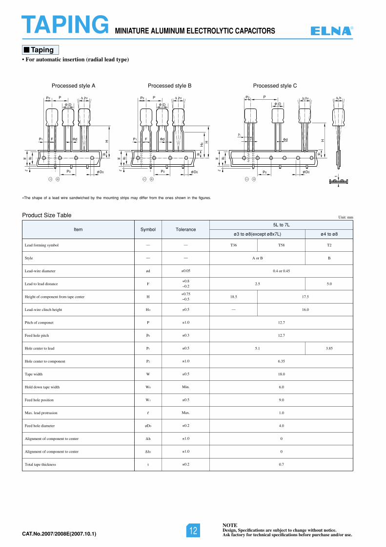
MINIATURE ALUMINUM ELECTROLYTIC CAPACITORSTAPINGTaping
• For automatic insertion (radial lead type)
CelytsdessecorPBelytsdessecorPAelytsdessecorP
h1P2 P
D
dFP1
P0 D0
W0
W1H
We
h1P2 h1P
D
P
D
dFP1 d
P0 D0 P0 D0
W0
W1H
0 H
W
HW1
e
W0We
h
t
P2
P1
F
Product Size Table
The shape of a lead wire sandwiched by the mounting strips may differ from the ones shown in the figures.
Unit: mm
Lead forming symbol
Style
Lead-wire diameter
Lead to lead distance
Height of component from tape center
Lead-wire clinch height
Pitch of componet
Feed hole pitch
Hole center to lead
Hole center to component
Tape width
Hold down tape width
Feed hole position
Max. lead protrusion
Feed hole diameter
Alignment of component to center
Alignment of component to center
Total tape thickness
ød
F
H
H0
P
P0
P1
P2
W
W0
W1
e
øD0
h
h1
t
0.05
0.5
1.0
0.3
0.5
1.0
0.5
Min.
0.5
Max.
0.2
1.0
1.0
0.2
0.80.2
——
— —
0.750.5
2T85T63T
BBroA
0.4 or 0.45
0.55.2
5.715.81
— 16.0
12.7
12.7
58.31.5
6.35
18.0
6.0
9.0
1.0
4.0
0
0
0.7
lobmySmetIø4 to ø8ø3 to ø8(except ø8x7L)
Tolerance5L to 7L
®
NOTEDesign, Specifications are subject to change without notice.Ask factory for technical specifications before purchase and/or use.12CAT.No.2007/2008E(2007.10.1)
CAT.No.2006/2007E(2006.10.1)13NOTEDesign, Specifications are subject to change without notice.Ask factory for technical specifications before purchase and/or use.
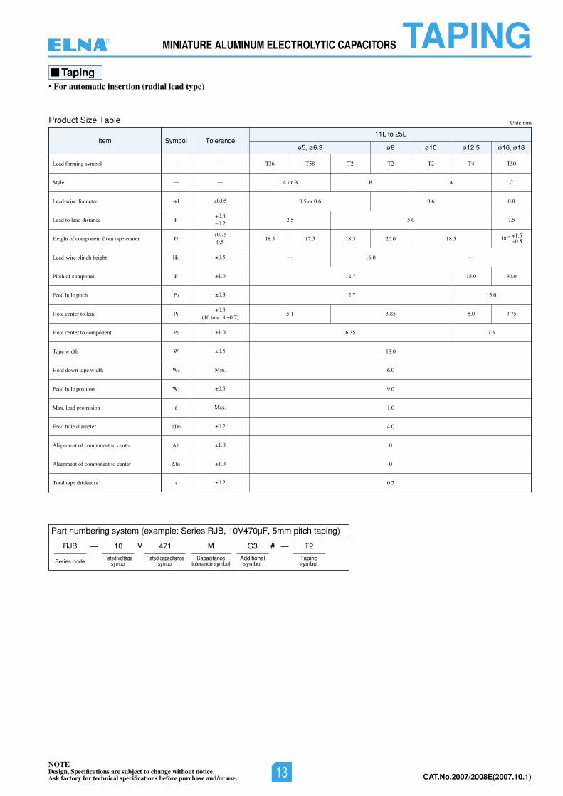
MINIATURE ALUMINUM ELECTROLYTIC CAPACITORS TAPINGTaping
• For automatic insertion (radial lead type)
Part numbering system (example: Series RJB, 10V470µF, 5mm pitch taping)
RJB —
Series code
—
Product Size Table Unit: mm
Lead forming symbol
Style
Lead-wire diameter
Lead to lead distance
Height of component from tape center
Lead-wire clinch height
Pitch of componet
Feed hole pitch
Hole center to lead
Hole center to component
Tape width
Hold down tape width
Feed hole position
Max. lead protrusion
Feed hole diameter
Alignment of component to center
Alignment of component to center
Total tape thickness
ød
F
H
H0
P
P0
P1
P2
W
W0
W1
e
øD0
h
h1
t
0.05
0.5
1.0
0.3
1.0
0.5
Min.
0.5
Max.
0.2
1.0
1.0
0.2
0.5(10 to ø18 0.7)
0.80.2
0.750.5
T36 T58 T2 T2 T2 T4 T50
CABBroA
8.06.06.0ro5.0
5.70.55.2
18.5 17.5 18.5 20.0 18.5
— 16.0 —
0.030.517.21
0.517.21
57.30.558.31.5
5.753.6
18.0
6.0
9.0
1.0
4.0
0
0
0.7
Item Symbolø16, ø18ø12.5ø10ø8ø5, ø6.3
Tolerance11L to 25L
1.518.5 0.5
V10 471 M G3 #
Additionalsymbol
T2
Tapingsymbol
Rated voltagesymbol
Rated capacitancesymbol
Capacitancetolerance symbol
——
— —
®
NOTEDesign, Specifications are subject to change without notice.Ask factory for technical specifications before purchase and/or use. 13 CAT.No.2007/2008E(2007.10.1)
CAT.No.2006/2007E(2006.10.1) 14NOTEDesign, Specifications are subject to change without notice.Ask factory for technical specifications before purchase and/or use.
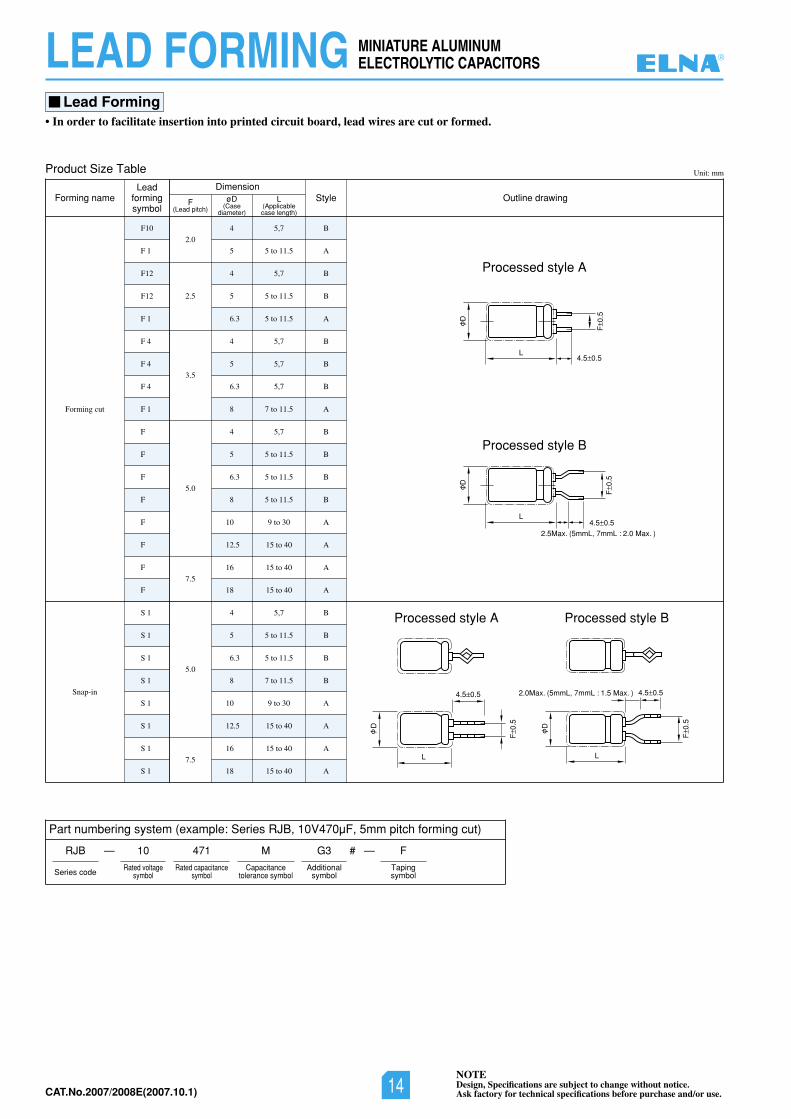
Lead Forming• In order to facilitate insertion into printed circuit board, lead wires are cut or formed.
Part numbering system (example: Series RJB, 10V470µF, 5mm pitch forming cut)
RJB —
Series code
—
Product Size Table Unit: mm
Forming cut
Snap-in
F10
F 1
F12
F12
F 1
F 4
F 4
F 4
F 1
F
F
F
F
F
F
F
F
S 1
S 1
S 1
S 1
S 1
S 1
S 1
S 1
2.0
2.5
3.5
5.0
7.5
5.0
7.5
4 5,7 B
5 5 to 11.5 A
4 5,7 B
5 5 to 11.5 B
6.3 5 to 11.5 A
4 5,7 B
5 5,7 B
6.3 5,7 B
8 7 to 11.5 A
4 5,7 B
5 5 to 11.5 B
6.3 5 to 11.5 B
8 5 to 11.5 B
10 9 to 30 A
12.5 15 to 40 A
16 15 to 40 A
18 15 to 40 A
4 5,7 B
5 5 to 11.5 B
6.3 5 to 11.5 B
8 7 to 11.5 B
10 9 to 30 A
12.5 15 to 40 A
16 15 to 40 A
18 15 to 40 A
Forming nameLead
formingsymbol
StyleDimension
F(Lead pitch)
øD(Case
diameter)
L(Applicablecase length)
Outline drawing
10 471 M G3
Additionalsymbol
F
Tapingsymbol
Rated voltagesymbol
Rated capacitancesymbol
Capacitancetolerance symbol
MINIATURE ALUMINUMELECTROLYTIC CAPACITORSLEAD FORMING
F0.
5
D
4.5 0.5L
F0.
5
F0.
5
D
D
4.5 0.52.5Max. (5mmL, 7mmL : 2.0 Max. )
L
4.5 0.52.0Max. (5mmL, 7mmL : 1.5 Max. )
L
Processed style A
Processed style B
Processed style BProcessed style A
4.5 0.5
L
F0.
5
D
#
®
NOTEDesign, Specifications are subject to change without notice.Ask factory for technical specifications before purchase and/or use.14CAT.No.2007/2008E(2007.10.1)
15NOTEDesign, Specifications are subject to change without notice.Ask factory for technical specifications before purchase and/or use. CAT.No.2006/2007E(2006.10.1)
ALUMINUM ELECTROLYTIC CAPACITORS WITH CONDUCTIVE POLYMER SOLID ELECTROLYTE
Aluminum Electrolytic CapacitorsWith Conductive Polymer Solid Electrolyte
®
Aluminum
Electrolytic Capacitors W
ith Conductive Polymer Solid
Electrolyte
NOTEDesign, Specifications are subject to change without notice.Ask factory for technical specifications before purchase and/or use. 15 CAT.No.2007/2008E(2007.10.1)

NOTEDesign, Specifications are subject to change without notice.Ask factory for technical specifications before purchase and/or use.CAT.No.2006/2007E(2006.10.1)
Please be sure to read this specification before using this product.Before placing an order, please inquire about the Product Specification to check details.
Cautions for Using Aluminum Electrolytic Capacitors With Conductive Polymer Solid Electrolyte
ALUMINUM ELECTROLYTIC CAPACITORSWITH CONDUCTIVE POLYMER SOLID ELECTROLYTETECHNICAL NOTE
Cautions for Usage
1. Solid conductive polymer aluminum electrolyticcapacitors are polarized. • Using a capacitor with reversed polarity causes
abnormal current flow, resulting in a short circuit.
2. Prohibited Circuits• Since leakage current problem may arise, capacitors
cannot be used in the following circuits.Coupling circuitsCircuits greatly affected by leakage current
3. Use capacitors within the rated voltage.• The application of voltages exceeding the rated
•
voltage can significantly increase leakage current,resulting in a short failure. Please do not apply avoltage exceeding the rated voltage.
4. Be careful of excessive rush current.• Using capacitors in the circuit where excessive
rush current passes may cause characteristicdeterioration or a short. When the rush currentexceeds 10 A, we recommend use of protectioncircuits to ensure high reliability.
5. Use the allowable ripple voltage and the ratedripple current below the specified values.•
• The rated ripple current shall be below the specifiedvalue.
6. Changes in characteristics due to operatingtemperature• The characteristics of solid conductive polymer
aluminum electrolytic capacitors vary by tempe-rature as follows. These variations are temporaryand recover when the temperature goes back(except for the case of characteristic deteriorationbecause of high temperatures over a long time).Note that using capacitors over the upper categorytemperature increases leakage current, resulting ina short and destruction.Be careful of the capacitor temperature consideringnot only the ambient temperature where theequipment is placed and the temperature inside theequipment but also radiation heat from the heatingelement inside the equipment, and self-heat
generation by ripple current.Capacitance expressed in the value at 20˚C, 120Hz increases with increased temperature anddecreases with decreasing temperature.Tangent of loss angle (tan ) expressed in thevalue at 20˚C, 120 Hz is temperature-independent.Equivalent series resistance (ESR) expressed inthe value at 20˚C, 100 kHz is temperature-independent.Leakage current increases with increasedtemperature and decreases with decreasingtemperature.
7. Changes in characteristics due to frequency• The characteristics of solid conductive polymer
aluminum electrolytic capacitors vary by operatingfrequency as follows.
Capacitance expressed in the value at 20˚C, 120Hz decreases with increased frequency.Tangent of loss angle (tan ) expressed in thevalue at 20˚C, 120 Hz increases with increasedfrequency.Equivalent series resistance (ESR) expressed inthe value at 20˚C, 100 kHz increases withdecreasing frequency.
8. Failure modes of solid conductive polymeraluminum electrolytic capacitors• The failure modes of solid conductive polymer
aluminum electrolytic capacitors are a wear-outfailure by deterioration of electrical performance anda random failure by a short. The failure rate level is1%/1,000h at the reliability level of 60% with thespecified voltage applied at 105˚C.
• If a short occurs and continues with the applicationof a voltage exceeding the rated voltage, increasingthe internal temperature, the internal pressureincreases by vaporization of the cathode material,which may cause the aluminum case to come off.
9. Operating environments• Do not store capacitors in an environment directly
exposed to water, saltwater spray, oil spill orcondensation.
• Do not store capacitors in an environment filled withtoxic gas such as hydrogen sulfide, sulfurous acid,nitrous acid, chlorine, ammonia, etc.
• Do not store capacitors in a place exposed to ozone,ultraviolet rays, or radiation.
10 . Fumigation Process
1
1
2
2
3
1
2
3
4
Cannot use for the circuit to which the polarity reverses by ripple voltage.
When superimposing a ripple voltage on a DC bias voltage, exercise care that the peak voltage value does not exceed the rated voltage and does not reverse the polarity.
®
NOTEDesign, Specifications are subject to change without notice.Ask factory for technical specifications before purchase and/or use.16CAT.No.2007/2008E(2007.10.1)
NOTEDesign, Specifications are subject to change without notice.Ask factory for technical specifications before purchase and/or use. CAT.No.2006/2007E(2006.10.1)
ALUMINUM ELECTROLYTIC CAPACITORSWITH CONDUCTIVE POLYMER SOLID ELECTROLYTE TECHNICAL NOTE
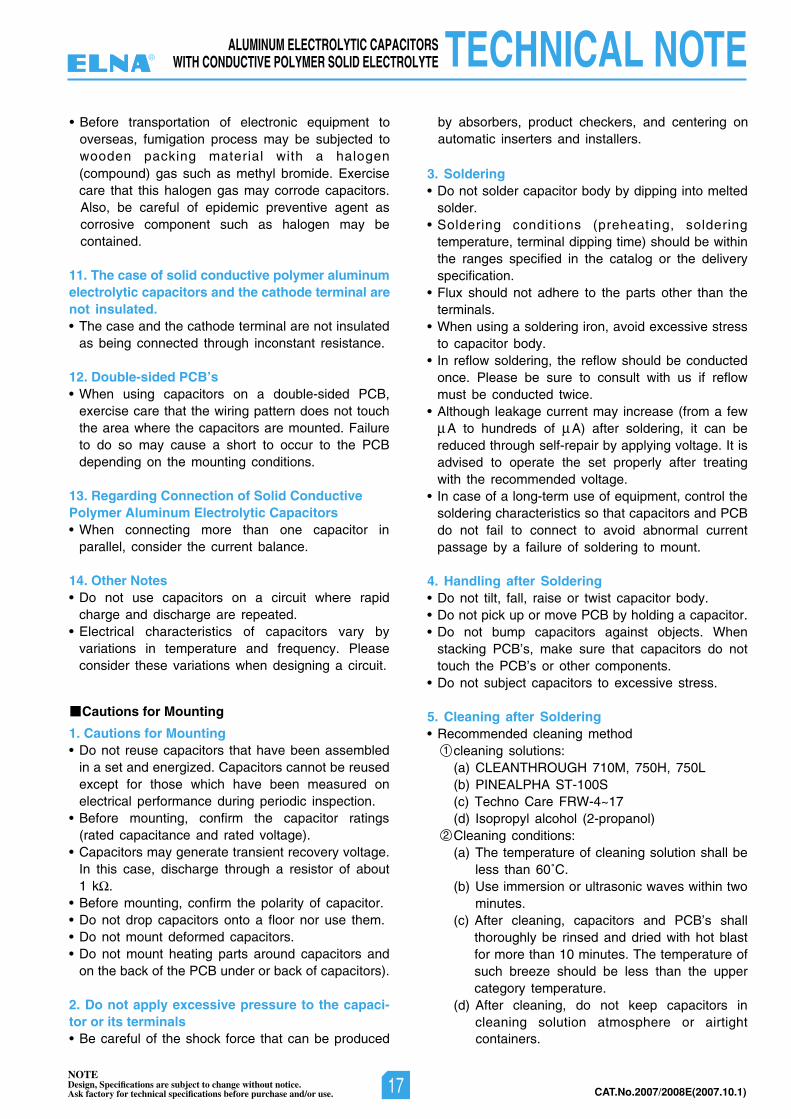
(compound) gas such as methyl bromide. Exercisecare that this halogen gas may corrode capacitors.Also, be careful of epidemic preventive agent ascorrosive component such as halogen may becontained.
11. The case of solid conductive polymer aluminumelectrolytic capacitors and the cathode terminal arenot insulated.• The case and the cathode terminal are not insulated
as being connected through inconstant resistance.
12. Double-sided PCB’s• When using capacitors on a double-sided PCB,
exercise care that the wiring pattern does not touchthe area where the capacitors are mounted. Failureto do so may cause a short to occur to the PCBdepending on the mounting conditions.
13. Regarding Connection of Solid ConductivePolymer Aluminum Electrolytic Capacitors• When connecting more than one capacitor in
parallel, consider the current balance.
14. Other Notes• Do not use capacitors on a circuit where rapid
charge and discharge are repeated.• Electrical characteristics of capacitors vary by
variations in temperature and frequency. Pleaseconsider these variations when designing a circuit.
1. Cautions for Mounting• Do not reuse capacitors that have been assembled
in a set and energized. Capacitors cannot be reusedexcept for those which have been measured onelectrical performance during periodic inspection.
• Before mounting, confirm the capacitor ratings(rated capacitance and rated voltage).
• Capacitors may generate transient recovery voltage.In this case, discharge through a resistor of about1 k .
• Before mounting, confirm the polarity of capacitor.• Do not drop capacitors onto a floor nor use them.• Do not mount deformed capacitors.• Do not mount heating parts around capacitors and
on the back of the PCB under or back of capacitors).
2. Do not apply excessive pressure to the capaci-tor or its terminals• Be careful of the shock force that can be produced
by absorbers, product checkers, and centering onautomatic inserters and installers.
3. Soldering• Do not solder capacitor body by dipping into melted
solder.• Soldering conditions (preheating, soldering
temperature, terminal dipping time) should be withinthe ranges specified in the catalog or the deliveryspecification.
• Flux should not adhere to the parts other than theterminals.
• When using a soldering iron, avoid excessive stressto capacitor body.
• In reflow soldering, the reflow should be conductedonce. Please be sure to consult with us if reflowmust be conducted twice.
• Although leakage current may increase (from a fewA to hundreds of A) after soldering, it can be
reduced through self-repair by applying voltage. It isadvised to operate the set properly after treatingwith the recommended voltage.
• In case of a long-term use of equipment, control thesoldering characteristics so that capacitors and PCBdo not fail to connect to avoid abnormal currentpassage by a failure of soldering to mount.
4. Handling after Soldering• Do not tilt, fall, raise or twist capacitor body.• Do not pick up or move PCB by holding a capacitor.• Do not bump capacitors against objects. When
stacking PCB’s, make sure that capacitors do nottouch the PCB’s or other components.
• Do not subject capacitors to excessive stress.
5. Cleaning after Soldering• Recommended cleaning method
cleaning solutions:(a) CLEANTHROUGH 710M, 750H, 750L(b) PINEALPHA ST-100S(c) Techno Care FRW-4~17(d) Isopropyl alcohol (2-propanol)Cleaning conditions:(a) The temperature of cleaning solution shall be
less than 60˚C.(b) Use immersion or ultrasonic waves within two
minutes.(c) After cleaning, capacitors and PCB’s shall
thoroughly be rinsed and dried with hot blastfor more than 10 minutes. The temperature ofsuch breeze should be less than the uppercategory temperature.
(d) After cleaning, do not keep capacitors incleaning solution atmosphere or airtight
Cautions for Mounting
1
2
• Before transportation of electronic equipment tooverseas, fumigation process may be subjected towooden packing material with a halogen
containers.
®
NOTEDesign, Specifications are subject to change without notice.Ask factory for technical specifications before purchase and/or use. 17 CAT.No.2007/2008E(2007.10.1)
CAT.No.2006/2007E(2006.10.1)
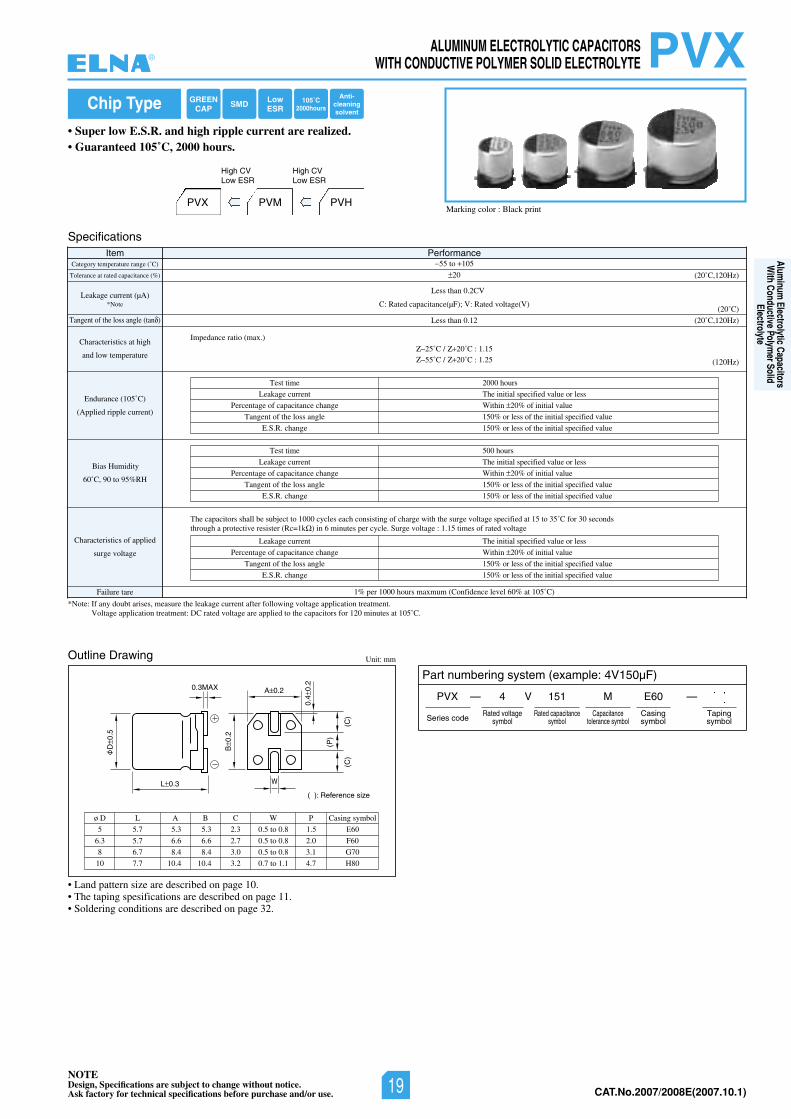
• Super low E.S.R. and high ripple current are realized.• Guaranteed 105˚C, 2000 hours.
NOTEDesign, Specifications are subject to change without notice.Ask factory for technical specifications before purchase and/or use.
Chip Type
Specifications
Outline Drawing
Item PerformanceCategory temperature range (˚C)
Tolerance at rated capacitance (%)
Leakage current (µA)
Tangent of the loss angle (tan )
Characteristics at high
and low temperature
Endurance (105˚C)
(Applied ripple current)
Bias Humidity
60˚C, 90 to 95%RH
Characteristics of applied
surge voltage
Failure tare
*Note: If any doubt arises, measure the leakage current after following voltage application treatment.Voltage application treatment: DC rated voltage are applied to the capacitors for 120 minutes at 105˚C.
1% per 1000 hours maxmum (Confidence level 60% at 105˚C)
55 to 105
20
C: Rated capacitance(µF); V: Rated voltage(V)(20˚C)
(20˚C,120Hz)
(20˚C,120Hz)
(120Hz)
Test time
Leakage current
Percentage of capacitance change
Tangent of the loss angle
E.S.R. change
2000 hours
The initial specified value or less
Within 20% of initial value
150% or less of the initial specified value
150% or less of the initial specified value
Test time
Leakage current
Percentage of capacitance change
Tangent of the loss angle
E.S.R. change
500 hours
The initial specified value or less
Within 20% of initial value
150% or less of the initial specified value
150% or less of the initial specified value
Leakage current
Percentage of capacitance change
Tangent of the loss angle
E.S.R. change
The initial specified value or less
Within 20% of initial value
150% or less of the initial specified value
150% or less of the initial specified value
55˚C / 20˚C : 1.25
Impedance ratio (max.)
25˚C / 20˚C : 1.15
Unit: mm
Part numbering system (example: 4V150µF)
PVX — V
Series code
4 151 M
Rated voltagesymbol
Rated capacitancesymbol
Capacitancetolerance symbol
E60
Casingsymbol
—
Tapingsymbol
PVXALUMINUM ELECTROLYTIC CAPACITORSWITH CONDUCTIVE POLYMER SOLID ELECTROLYTE
Less than 0.12
Less than 0.2CV
The capacitors shall be subject to 1000 cycles each consisting of charge with the surge voltage specified at 15 to 35˚C for 30 seconds through a protective resister (Rc=1k ) in 6 minutes per cycle. Surge voltage : 1.15 times of rated voltage
L 0.3
D0.
5
B0.
2
(P)
(C)
(C)
0.4
0.2
A 0.2
( ): Reference size
0.3MAX
W
6.3
8
10
ø D
5.7
6.7
7.7
L
6.6
8.4
10.4
A
6.6
8.4
10.4
B
2.7
3.0
3.2
C
0.5 to 0.8
0.5 to 0.8
0.7 to 1.1
W
F60
G70
H80
Casing symbol
2.0
3.1
4.7
P
*Note
• Land pattern size are described on page 10.• The taping spesifications are described on page 11.• Soldering conditions are described on page 32.
GREENCAP
LowESRSMD 105˚C
2000hours
Anti-cleaningsolvent
5 5.7 5.3 5.3 2.3 0.5 to 0.8 1.5 E60
PVM PVHPVX
High CVLow ESR
High CVLow ESR
Marking color : Black print
®
Aluminum
Electrolytic Capacitors W
ith Conductive Polymer Solid
Electrolyte
NOTEDesign, Specifications are subject to change without notice.Ask factory for technical specifications before purchase and/or use. 19 CAT.No.2007/2008E(2007.10.1)
NOTEDesign, Specifications are subject to change without notice.Ask factory for technical specifications before purchase and/or use.CAT.No.2006/2007E(2006.10.1)
PVX ALUMINUM ELECTROLYTIC CAPACITORSWITH CONDUCTIVE POLYMER SOLID ELECTROLYTE
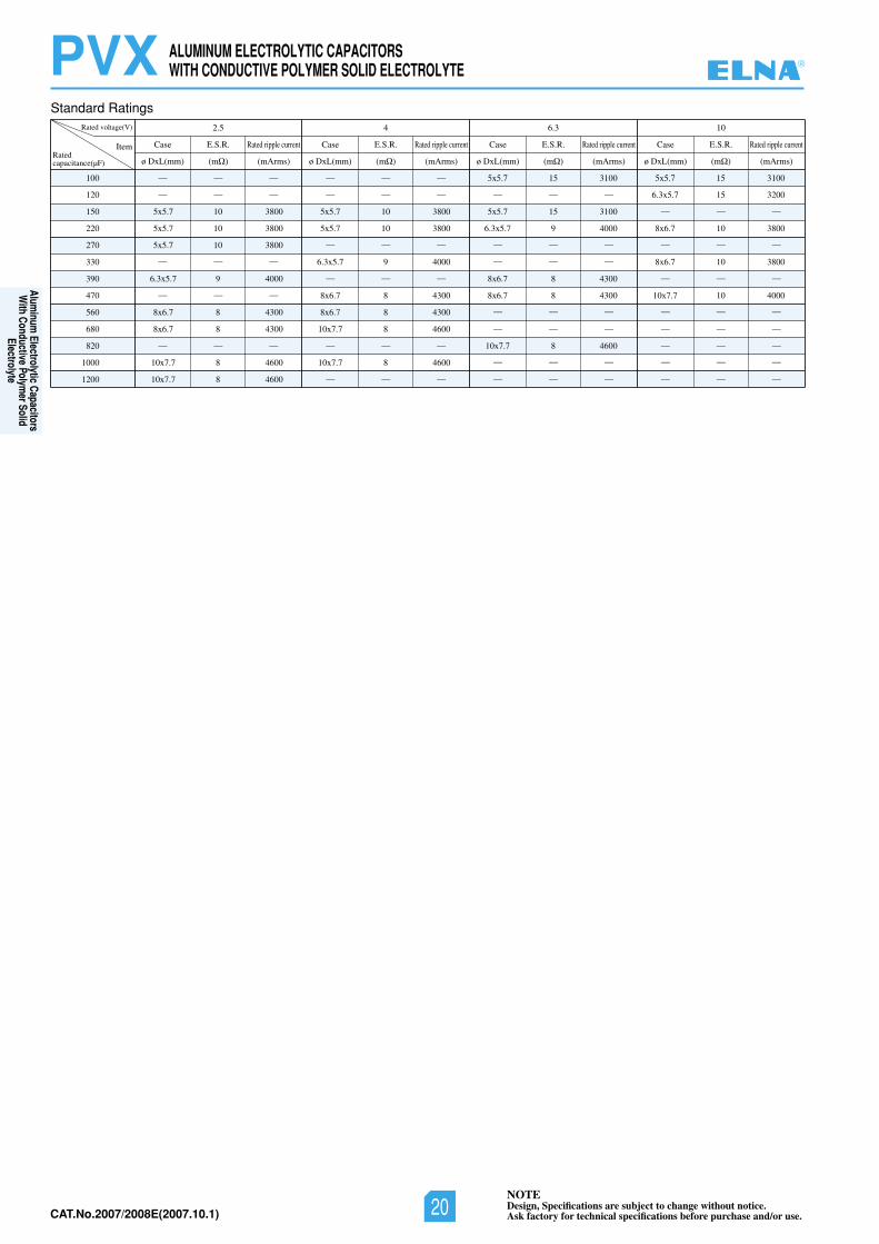
Standard Ratings
100
120
150
220
270
330
390
470
560
680
820
1000
1200
5x5.7
5x5.7
5x5.7
6.3x5.7
8x6.7
8x6.7
10x7.7
10x7.7
10
10
10
9
8
8
8
8
3800
3800
3800
4000
4300
4300
4600
4600
5x5.7
5x5.7
6.3x5.7
8x6.7
8x6.7
10x7.7
10x7.7
10
10
9
8
8
8
8
3800
3800
4000
4300
4300
4600
4600
5x5.7
5x5.7
6.3x5.7
8x6.7
8x6.7
10x7.7
15
15
9
8
8
8
3100
3100
4000
4300
4300
4600
5x5.7
6.3x5.7
8x6.7
8x6.7
10x7.7
15
15
10
10
10
3100
3200
3800
3800
4000
Rated voltage(V) 013.645.2
Item
— — —
— — —
— — —
— — —
— — —
Case E.S.R.
ø DxL(mm) (m ) (mArms)
Rated ripple current Case E.S.R.
ø DxL(mm) (m ) (mArms)
Rated ripple current Case E.S.R.
ø DxL(mm) (m ) (mArms)
Rated ripple current Case E.S.R.
ø DxL(mm) (m ) (mArms)
Rated ripple currentRatedcapacitance(µF)
— — —
— — —
— — —
— — —
— — —
— — —
— — —
— — —
— — —
— — —
— — —
— — —
— — —
— — —
— — —
— — —
— — —
— — —
— — —
— — —
— — —
®
Aluminum
Electrolytic Capacitors W
ith Conductive Polymer Solid
Electrolyte
NOTEDesign, Specifications are subject to change without notice.Ask factory for technical specifications before purchase and/or use.20CAT.No.2007/2008E(2007.10.1)
CAT.No.2006/2007E(2006.10.1)
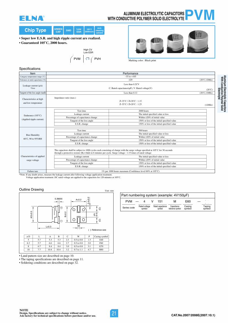
• Super low E.S.R. and high ripple current are realized.• Guaranteed 105˚C, 2000 hours.
NOTEDesign, Specifications are subject to change without notice.Ask factory for technical specifications before purchase and/or use.
Chip Type
Specifications
Outline Drawing
Item PerformanceCategory temperature range (˚C)
Tolerance at rated capacitance (%)
Leakage current (µA)
Tangent of the loss angle (tan )
Characteristics at high
and low temperature
Endurance (105˚C)
(Applied ripple current)
Characteristics of applied
surge voltage
Failure tare
*Note: If any doubt arises, measure the leakage current after following voltage application treatment.Voltage application treatment: DC rated voltage are applied to the capacitors for 120 minutes at 105˚C.
1% per 1000 hours maxmum (Confidence level 60% at 105˚C)
55 to 105
20
C: Rated capacitance(µF); V: Rated voltage(V)(20˚C)
(20˚C,120Hz)
(20˚C,120Hz)
(120Hz)
Test time
Leakage current
Percentage of capacitance change
Tangent of the loss angle
E.S.R. change
2000 hours
The initial specified value or less
Within 20% of initial value
150% or less of the initial specified value
150% or less of the initial specified value
Test time
Leakage current
Percentage of capacitance change
Tangent of the loss angle
E.S.R. change
500 hours
The initial specified value or less
Within 20% of initial value
150% or less of the initial specified value
150% or less of the initial specified value
Leakage current
Percentage of capacitance change
Tangent of the loss angle
E.S.R. change
The initial specified value or less
Within 20% of initial value
150% or less of the initial specified value
150% or less of the initial specified value
55˚C / 20˚C : 1.25
Impedance ratio (max.)
25˚C / 20˚C : 1.15
Unit: mm
Part numbering system (example: 4V150µF)
PVM — V
Series code
4 151 M
Rated voltagesymbol
Rated capacitancesymbol
Capacitancetolerance symbol
E60
Casingsymbol
—
Tapingsymbol
PVM
Less than 0.12
Less than 0.2CV
The capacitors shall be subject to 1000 cycles each consisting of charge with the surge voltage specified at 105˚C for 30 seconds through a protective resister (Rc=1k ) in 6 minutes per cycle. Surge voltage : 1.15 times of rated voltage
L 0.3
D0.
5
B0.
2
(P)
(C)
(C)
0.4
0.2
A 0.2
( ): Reference size
0.3MAX
W
6.3
8
10
ø D
5.7
6.7
7.7
L
6.6
8.4
10.4
A
6.6
8.4
10.4
B
2.7
3.0
3.2
C
0.5 to 0.8
0.5 to 0.8
0.7 to 1.1
W
F60
G70
H80
Casing symbol
2.0
3.1
4.7
P
*Note
• Land pattern size are described on page 10.• The taping spesifications are described on page 11.• Soldering conditions are described on page 32.
GREENCAP
LowESRSMD 105˚C
2000hours
Anti-cleaningsolvent
5 5.7 5.3 5.3 2.3 0.5 to 0.8 1.5 E60
PVM PVH
High CVLow ESR
ALUMINUM ELECTROLYTIC CAPACITORSWITH CONDUCTIVE POLYMER SOLID ELECTROLYTE
Bias Humidity
60˚C, 90 to 95%RH
Marking color : Black print
®
Aluminum
Electrolytic Capacitors W
ith Conductive Polymer Solid
Electrolyte
NOTEDesign, Specifications are subject to change without notice.Ask factory for technical specifications before purchase and/or use. 21 CAT.No.2007/2008E(2007.10.1)
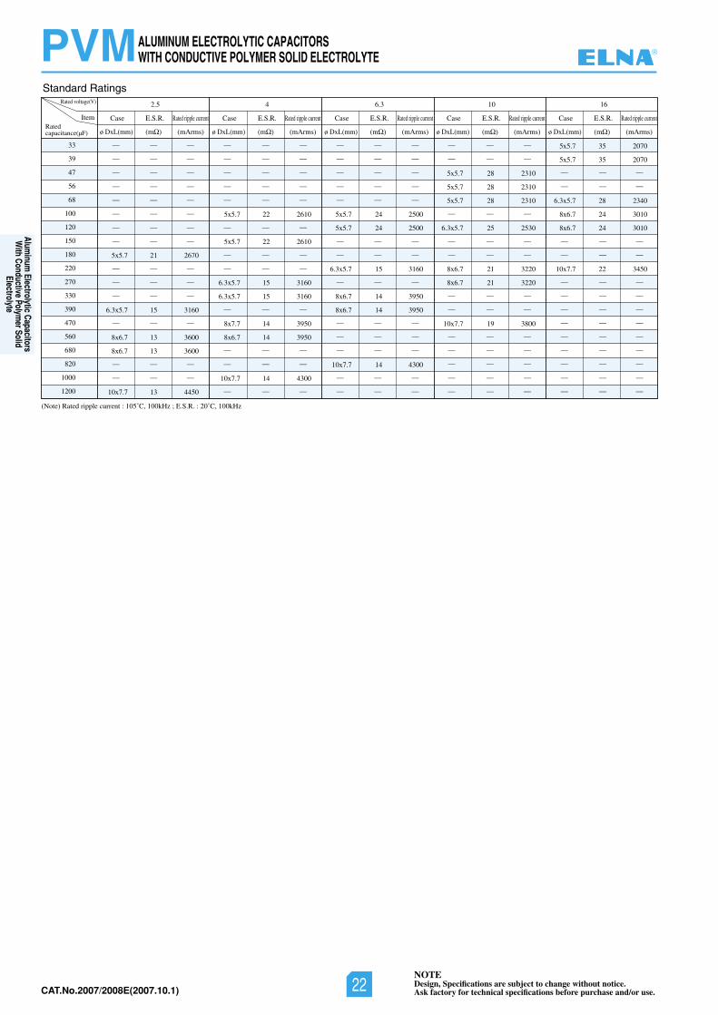
Standard Ratings
(Note) Rated ripple current : 105˚C, 100kHz ; E.S.R. : 20˚C, 100kHz
NOTEDesign, Specifications are subject to change without notice.Ask factory for technical specifications before purchase and/or use.CAT.No.2006/2007E(2006.10.1)
PVM
— — —
— — —
— — —
— — —
— — —
— — —
— — —
— — —
— — —
— — —
— — —
— — —
— — —
— — —
— — —
— — —
— — —
— — —
— — —
— — —
— — —
— — —
— — —
— — —
— — —
— — —
— — —
— — —
— — —
— — —
— — —
— — —
— — —
— — —
— — —
— — —
— — —
— — —
— — —
— — —
— — —
— — —
— — —
— — —
— — —
— — —
— — —
— — —
— — —
— — —
— — — — — —
— — —
— — —
— — —
— — —
— — —
— — —
— — —
— — —
— — —
— — —
— — —
— — —
33
39
47
56
68
100
120
150
180
220
270
330
390
470
560
680
820
1000
1200
5x5.7
6.3x5.7
8x6.7
8x6.7
10x7.7
21
15
13
13
13
2670
3160
3600
3600
4450
5x5.7
5x5.7
6.3x5.7
6.3x5.7
8x7.7
8x6.7
10x7.7
22
22
15
15
14
14
14
2610
2610
3160
3160
3950
3950
4300
5x5.7
5x5.7
6.3x5.7
8x6.7
8x6.7
10x7.7
24
24
15
14
14
14
2500
2500
3160
3950
3950
4300
5x5.7
5x5.7
5x5.7
6.3x5.7
8x6.7
8x6.7
10x7.7
28
28
28
25
21
21
19
2310
2310
2310
2530
3220
3220
3800
5x5.7
5x5.7
6.3x5.7
8x6.7
8x6.7
10x7.7
35
35
28
24
24
22
2070
2070
2340
3010
3010
3450
Rated voltage(V) 2.5 4 6.3 10 16
ItemRatedcapacitance(µF)
Case E.S.R. Rated ripple current
ø DxL(mm) (m (mArms)
Case E.S.R. Rated ripple current
ø DxL(mm) (m (mArms)
Case E.S.R. Rated ripple current
ø DxL(mm) (m (mArms)
Case E.S.R. Rated ripple current
ø DxL(mm) (m (mArms)
Case E.S.R. Rated ripple current
ø DxL(mm) (m (mArms)
ALUMINUM ELECTROLYTIC CAPACITORSWITH CONDUCTIVE POLYMER SOLID ELECTROLYTE ®
Aluminum
Electrolytic Capacitors W
ith Conductive Polymer Solid
Electrolyte
NOTEDesign, Specifications are subject to change without notice.Ask factory for technical specifications before purchase and/or use.22CAT.No.2007/2008E(2007.10.1)
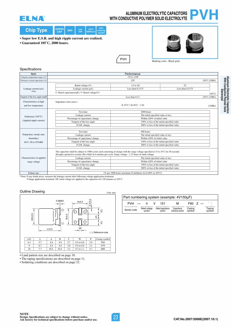
CAT.No.2006/2007E(2006.10.1)
• Super low E.S.R. and high ripple current are realized.• Guaranteed 105˚C, 2000 hours.
NOTEDesign, Specifications are subject to change without notice.Ask factory for technical specifications before purchase and/or use.
Chip Type
Marking color : Black print
Specifications
Outline Drawing
Item PerformanceCategory temperature range (˚C)
Tolerance at rated capacitance (%)
Leakage current (µA)
Tangent of the loss angle (tan )
Characteristics at high
and low temperature
Endurance (105˚C)
(Applied ripple current)
Damp heat, steady state
(humidity)
60˚C, 90 to 95%RH
Characteristics of applied
surge voltage
Failure tare
*Note: If any doubt arises, measure the leakage current after following voltage application treatment.Voltage application treatment: DC rated voltage are applied to the capacitors for 120 minutes at 105˚C.
1% per 1000 hours maxmum (Confidence level 60% at 105˚C)
55 to 105
20
C: Rated capacitance(µF); V: Rated voltage(V)
5202ot5.2)V(egatlovdetaR
VC5.0nahtsseLVC2.0nahtsseLLeakage current (µA)
(20˚C)
(20˚C,120Hz)
(20˚C,120Hz)
(120Hz)
Test time
Leakage current
Percentage of capacitance change
Tangent of the loss angle
E.S.R. change
2000 hours
The initial specified value or less
Within 20% of initial value
150% or less of the initial specified value
200% or less of the initial specified value
Test time
Leakage current
Percentage of capacitance change
Tangent of the loss angle
E.S.R. change
500 hours
The initial specified value or less
Within 20% of initial value
150% or less of the initial specified value
200% or less of the initial specified value
Leakage current
Percentage of capacitance change
Tangent of the loss angle
E.S.R. change
The initial specified value or less
Within 20% of initial value
150% or less of the initial specified value
200% or less of the initial specified value
Impedance ratio (max.)
55˚C / 20˚C : 1.50
Unit: mm
Part numbering system (example: 4V150µF)
PVH — V
Series code
4 151 M
Rated voltagesymbol
Rated capacitancesymbol
Capacitancetolerance symbol
F60
Casingsymbol
—
Tapingsymbol
PVH
Less than 0.12
The capacitors shall be subject to 1000 cycles each consisting of charge with the surge voltage specified at 15 to 35˚C for 30 seconds through a protective resister (Rc=1k ) in 6 minutes per cycle. Surge voltage : 1.15 times of rated voltage
L 0.3
D0.
5
B0.
2
(P)
(C)
(C)
0.4
0.2
A 0.2
( ): Reference size
0.3MAX
W
6.3
8
10
ø D
5.7
6.7
7.7
L
6.6
8.4
10.4
A
6.6
8.4
10.4
B
2.7
3.0
3.2
C
0.5 to 0.8
0.5 to 0.8
0.7 to 1.1
W
F60
G70
H80
Casing symbol
2.0
3.1
4.7
P
*Note
• Land pattern size are described on page 10.• The taping spesifications are described on page 11.• Soldering conditions are described on page 32.
PVH
GREENCAP SMD Low
ESR105˚C
2000hours
Anti-cleaningsolvent
Z
ALUMINUM ELECTROLYTIC CAPACITORSWITH CONDUCTIVE POLYMER SOLID ELECTROLYTE®
Aluminum
Electrolytic Capacitors W
ith Conductive Polymer Solid
Electrolyte
NOTEDesign, Specifications are subject to change without notice.Ask factory for technical specifications before purchase and/or use. 23 CAT.No.2007/2008E(2007.10.1)
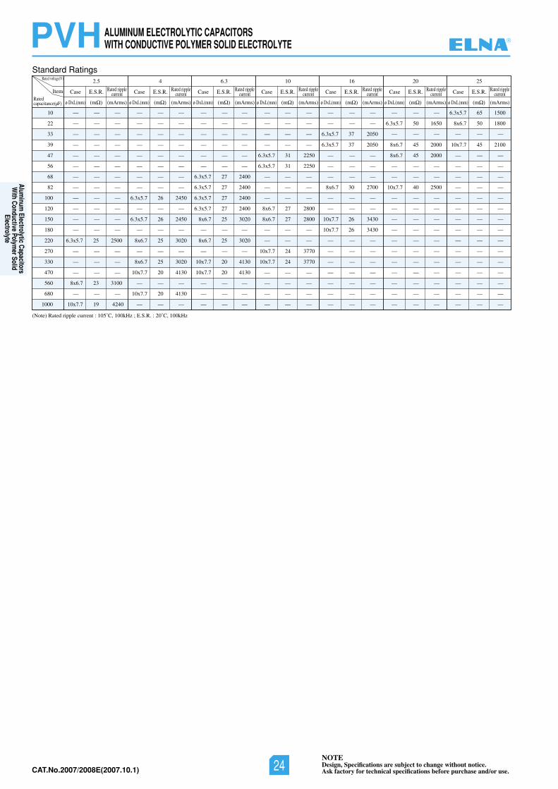
NOTEDesign, Specifications are subject to change without notice.Ask factory for technical specifications before purchase and/or use. CAT.No.2006/2007E(2006.10.1)
PVHStandard Ratings
(Note) Rated ripple current : 105˚C, 100kHz ; E.S.R. : 20˚C, 100kHz
ALUMINUM ELECTROLYTIC CAPACITORSWITH CONDUCTIVE POLYMER SOLID ELECTROLYTE
10
22
33
39
47
56
68
82
100
120
150
180
220
270
330
470
560
680
1000
6.3x5.7 25 2500
8x6.7 23 3100
10x7.7 19 4240
6.3x5.7 26 2450
6.3x5.7 26 2450
8x6.7 25 3020
8x6.7 25 3020
10x7.7 20 4130
10x7.7 20 4130
6.3x5.7 27 2400
6.3x5.7 27 2400
6.3x5.7 27 2400
6.3x5.7 27 2400
8x6.7 25 3020
8x6.7 25 3020
10x7.7 20 4130
10x7.7 20 4130
6.3x5.7 31 2250
6.3x5.7 31 2250
8x6.7 27 2800
8x6.7 27 2800
10x7.7 24 3770
10x7.7 24 3770
6.3x5.7 37 2050
6.3x5.7 37 2050
8x6.7 30 2700
10x7.7 26 3430
10x7.7 26 3430
6.3x5.7 50 1650
8x6.7 45 2000
8x6.7 45 2000
10x7.7 40 2500
6.3x5.7 65 1500
8x6.7 50 1800
10x7.7 45 2100
—
—
—
—
—
—
—
—
—
—
—
—
—
—
—
—
—
—
—
—
—
—
—
—
—
—
—
—
—
—
—
—
—
—
—
—
—
—
—
—
—
—
—
—
—
—
—
—
—
—
—
—
—
—
—
—
—
—
—
—
—
—
—
—
—
—
—
—
—
—
—
—
—
—
—
—
—
—
—
—
—
—
—
—
—
—
—
—
—
—
—
—
—
—
—
—
—
—
—
—
—
—
—
—
—
—
—
—
—
—
—
—
—
—
—
—
—
—
—
—
—
—
—
—
—
—
—
—
—
—
—
—
—
—
—
—
—
—
—
—
—
—
—
—
—
—
—
—
—
—
—
—
—
—
—
—
—
—
—
—
—
—
—
—
—
—
—
—
—
—
—
—
—
—
—
—
—
—
—
—
—
—
—
—
—
—
—
—
—
—
—
—
—
—
—
—
—
—
—
—
—
—
—
—
—
—
—
—
—
—
—
—
—
—
—
—
—
—
—
—
—
—
—
—
—
—
—
—
—
—
—
—
—
—
—
—
—
—
—
—
—
—
—
—
—
—
—
—
—
—
—
—
—
—
—
—
—
—
—
—
—
—
—
—
—
—
—
—
—
—
—
—
—
—
—
—
—
—
—
—
—
—
—
—
—
—
—
—
—
—
—
—
—
—
Rated voltage(V) 2.5
Item
capacitance(µF)Rated
Case E.S.R. Rated ripplecurrent
ø DxL(mm) (m (mArms)
4
Case E.S.R. Rated ripplecurrent
ø DxL(mm) (m (mArms)
6.3
Case E.S.R. Rated ripplecurrent
ø DxL(mm) (m (mArms)
10
Case E.S.R. Rated ripplecurrent
ø DxL(mm) (m (mArms)
16
Case E.S.R. Rated ripplecurrent
ø DxL(mm) (m (mArms)
20
Case E.S.R. Rated ripplecurrent
ø DxL(mm) (m (mArms)
25
Case E.S.R. Rated ripplecurrent
ø DxL(mm) (m (mArms)
®
Aluminum
Electrolytic Capacitors W
ith Conductive Polymer Solid
Electrolyte
NOTEDesign, Specifications are subject to change without notice.Ask factory for technical specifications before purchase and/or use.24CAT.No.2007/2008E(2007.10.1)
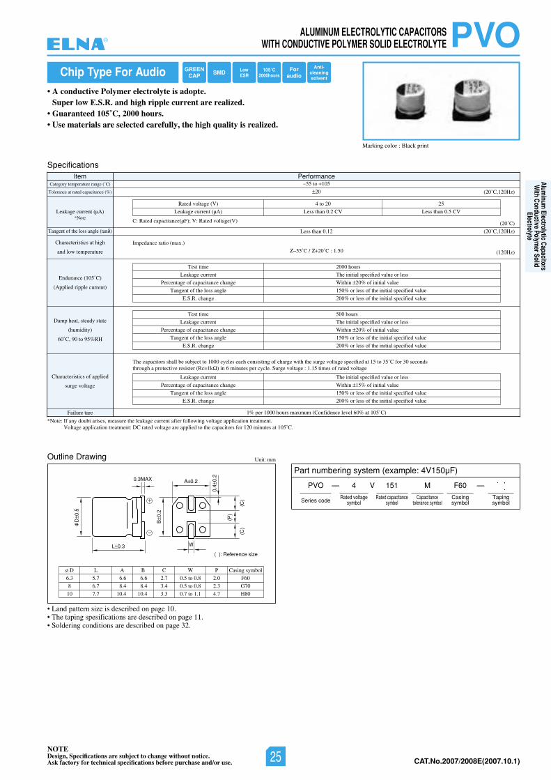
CAT.No.2006/2007E(2006.10.1)
NOTEDesign, Specifications are subject to change without notice.Ask factory for technical specifications before purchase and/or use.
Chip Type For Audio
• A conductive Polymer electrolyte is adopte.Super low E.S.R. and high ripple current are realized.
• Guaranteed 105˚C, 2000 hours.• Use materials are selected carefully, the high quality is realized.
Marking color : Black print
Specifications
Outline Drawing
Item PerformanceCategory temperature range (˚C)
Tolerance at rated capacitance (%)
Leakage current (µA)
Tangent of the loss angle (tan )
Characteristics at high
and low temperature
Endurance (105˚C)
(Applied ripple current)
Damp heat, steady state
(humidity)
60˚C, 90 to 95%RH
Characteristics of applied
surge voltage
Failure tare
*Note: If any doubt arises, measure the leakage current after following voltage application treatment.Voltage application treatment: DC rated voltage are applied to the capacitors for 120 minutes at 105˚C.
1% per 1000 hours maxmum (Confidence level 60% at 105˚C)
55 to 105
20
C: Rated capacitance(µF); V: Rated voltage(V)
5202ot4)V(egatlovdetaR
VC5.0nahtsseLVC2.0nahtsseLLeakage current (µA)
(20˚C)
(20˚C,120Hz)
(20˚C,120Hz)
(120Hz)
Test time
Leakage current
Percentage of capacitance change
Tangent of the loss angle
E.S.R. change
2000 hours
The initial specified value or less
Within 20% of initial value
150% or less of the initial specified value
200% or less of the initial specified value
Test time
Leakage current
Percentage of capacitance change
Tangent of the loss angle
E.S.R. change
500 hours
The initial specified value or less
Within 20% of initial value
150% or less of the initial specified value
200% or less of the initial specified value
Leakage current
Percentage of capacitance change
Tangent of the loss angle
E.S.R. change
The initial specified value or less
Within 15% of initial value
150% or less of the initial specified value
200% or less of the initial specified value
Impedance ratio (max.)
55˚C / 20˚C : 1.50
Unit: mm
Part numbering system (example: 4V150µF)
PVO — V
Series code
4 151 M
Rated voltagesymbol
Rated capacitancesymbol
Capacitancetolerance symbol
F60
Casingsymbol
—
Tapingsymbol
PVO
Less than 0.12
The capacitors shall be subject to 1000 cycles each consisting of charge with the surge voltage specified at 15 to 35˚C for 30 seconds through a protective resister (Rc=1k ) in 6 minutes per cycle. Surge voltage : 1.15 times of rated voltage
L 0.3
D0.
5
B0.
2
(P)
(C)
(C)
0.4
0.2
A 0.2
( ): Reference size
0.3MAX
W
6.3
8
10
ø D
5.7
6.7
7.7
L
6.6
8.4
10.4
A
6.6
8.4
10.4
B
2.7
3.4
3.3
C
0.5 to 0.8
0.5 to 0.8
0.7 to 1.1
W
F60
G70
H80
Casing symbol
2.0
2.3
4.7
P
*Note
• Land pattern size is described on page 10.• The taping spesifications are described on page 11.• Soldering conditions are described on page 32.
GREENCAP SMD Low
ESR105˚C
2000hoursFor
audio
Anti-cleaningsolvent
ALUMINUM ELECTROLYTIC CAPACITORSWITH CONDUCTIVE POLYMER SOLID ELECTROLYTE®
Aluminum
Electrolytic Capacitors W
ith Conductive Polymer Solid
Electrolyte
NOTEDesign, Specifications are subject to change without notice.Ask factory for technical specifications before purchase and/or use. 25 CAT.No.2007/2008E(2007.10.1)
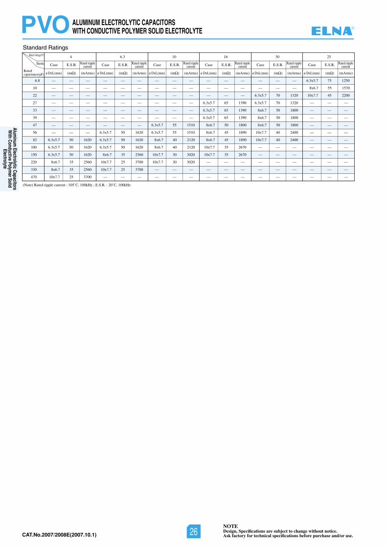
CAT.No.2006/2007E(2006.10.1)
NOTEDesign, Specifications are subject to change without notice.Ask factory for technical specifications before purchase and/or use.
PVOStandard Ratings
(Note) Rated ripple current : 105˚C, 100kHz ; E.S.R. : 20˚C, 100kHz
6.8
10
22
27
33
39
47
56
82
100
150
220
330
470
6.3x5.7 50 1620
6.3x5.7 50 1620
6.3x5.7 50 1620
8x6.7 35 2560
8x6.7 35 2560
10x7.7 25 3700
6.3x5.7 50 1620
6.3x5.7 50 1620
6.3x5.7 50 1620
8x6.7 35 2560
10x7.7 25 3700
10x7.7 25 3700
6.3x5.7 55 1510
6.3x5.7 55 1510
8x6.7 40 2120
8x6.7 40 2120
10x7.7 30 3020
10x7.7 30 3020
6.3x5.7 65 1390
6.3x5.7 65 1390
6.3x5.7 65 1390
8x6.7 50 1800
8x6.7 45 1890
8x6.7 45 1890
10x7.7 35 2670
10x7.7 35 2670
6.3x5.7 70 1320
6.3x5.7 70 1320
8x6.7 50 1800
8x6.7 50 1800
8x6.7 50 1800
10x7.7 40 2400
10x7.7 40 2400
6.3x5.7 75 1250
8x6.7 55 1570
10x7.7 45 2200
—
—
—
—
—
—
—
—
—
—
—
—
—
—
—
—
—
—
—
—
—
—
—
—
—
—
—
—
—
—
—
—
—
—
—
—
—
—
—
—
—
—
—
—
—
—
—
—
—
—
—
—
—
—
—
—
—
—
—
—
—
—
—
—
—
—
—
—
—
—
—
—
—
—
—
—
—
—
—
—
—
—
—
—
—
—
—
—
—
—
—
—
—
—
—
—
—
—
—
—
—
—
—
—
—
—
—
—
—
—
—
—
—
—
—
—
—
—
—
—
—
—
—
—
—
—
—
—
—
—
—
—
—
—
—
—
—
—
—
—
—— — —
Rated voltage(V) 4
Item Case E.S.R. Rated ripplecurrent
ø DxL(mm) (m (mArms)
6.3
Case E.S.R. Rated ripplecurrent
ø DxL(mm) (m (mArms)
10
Case E.S.R. Rated ripplecurrent
ø DxL(mm) (m (mArms)
16
Case E.S.R. Rated ripplecurrent
ø DxL(mm) (m (mArms)
30
Case E.S.R. Rated ripplecurrent
ø DxL(mm) (m (mArms)
25
Case E.S.R. Rated ripplecurrent
ø DxL(mm) (m (mArms)Ratedcapacitance(µF)
ALUMINUM ELECTROLYTIC CAPACITORSWITH CONDUCTIVE POLYMER SOLID ELECTROLYTE ®
Aluminum
Electrolytic Capacitors W
ith Conductive Polymer Solid
Electrolyte
NOTEDesign, Specifications are subject to change without notice.Ask factory for technical specifications before purchase and/or use.26CAT.No.2007/2008E(2007.10.1)
23NOTEDesign, Specifications are subject to change without notice.Ask factory for technical specifications before purchase and/or use. CAT.No.2006/2007E(2006.10.1)
Chip Type, Miniature and Large CapacitanceAluminum Electrolytic Capacitors
ALUMINUM ELECTROLYTIC CAPACITORS®
NOTEDesign, Specifications are subject to change without notice.Ask factory for technical specifications before purchase and/or use. 27 CAT.No.2007/2008E(2007.10.1)
Chip Type, Miniature
and Large CapacitanceAlum
inum Electrolytic Capacitors
CAT.No.2006/2007E(2006.10.1) 24NOTEDesign, Specifications are subject to change without notice.Ask factory for technical specifications before purchase and/or use.
ALUMINUM ELECTROLYTIC CAPACITORS
Please read product specifications before using ELNA products.
The following cautions should be observed when using our aluminum electrolytic capacitors to assure their maximumstability and performance. When your application design conditions or operating conditions exceed the limit of theproduct specification, please contact us. If used under conditions beyond the limit of our specifications, it may causedefects such as short circuit, open circuit, leakage, explosion or combustion.
Cautions for usage
Cautions for Using Aluminum Electrolytic Capacitors
1. DC electrolytic capacitors are polarized. • If used with a wrong polarity, it creates an abnormal
current resulting in a short circuit or damage toitself. Use DC bipolar electrolytic capacitors for usewith uncertain or unknown polarity. DC capacitorscannot be used in AC circuits.
2. Use within the rated voltage. • If a voltage exceeding the rated voltage is applied,
it may cause characteristic deterioration or damagedue to the increased leakage current.
• When ripple current is loaded, make sure that thepeak value of the ripple voltage does not exceedthe rated voltage.
3. Using for powar supply circuit.• While aluminum electrolytic capacitors are operated
electrolyte liquid inside dries up and E.S.R.(Equivalent Series Resistance) of the capacitorincreases. In case operated longer than rated lifetime, the capacitance much decreases, tangent ofloss angle and E.S.R. much increases. Thereforefor some case the sum of bias direct voltage andthe peak of ripple voltage is over the rated voltageof the capacitor.
• For any type of circuit, in case the sum of biasdirect voltage and the peak of ripple voltage is overthe rated voltage of the capacitors or in case theminimum voltage is lower than 0 (zero) volt, thevoltage control for the capacitors shall be provided.
4. Do not use in a circuit which requires rapidcharging or discharging.
• If used in a circuit requiring rapid charging or dis-charging, it may cause characteristic deteriorationor damage to itself due to the heat generated insidethe capacitor. In such cases, contact us for ourrapid charging/discharging capacitors.
5. Use within the rated ripple current.• If applied ripple current exceeds rated ripple current,
the life of the capacitor may be shortened, or in anextreme case it gets destroyed due to its internal heat.Use high-ripple type capacitors for such circuits.
6. Changes in characteristics due to operatingtemperature.
• The characteristics of an electrolytic capacitor willchange with a change in the temperature. Suchchanges are temporary and the original characteris-tics will be restored at the original temperature (if
the characteristics are not deteriorated byremaining at a high temperature for a long time). Ifused at a temperature exceeding the guaranteedtemperature range, the capacitor may be damageddue to the increased leakage current. Pay attentionto the capacitor temperature being affected by theambient temperature of the unit, the temperatureinside the appliance, the heat radiated by anotherhot component in the unit and the heat inside thecapacitor itself due to the ripple current.(1)The electrostatic capacitance is normally shown
as the value at 20˚C-120Hz. It increases as thetemperature raises and decreases as it lowers.
(2)The tangent of loss angle (tan ) is normallyshown as the value at 20˚C-120Hz. It decreasesas the ambient temperature gets high andincreases as it gets low.
(3)The leakage current increases as the tem-perature gets high and decreases as it gets low.
7. Changes in the characteristics due to frequency.• The characteristics of an electrolytic capacitor will
change according to the change in the operatingfrequency.(1)The electrostatic capacity is normally shown as
the value at 20˚C-120Hz. It decreases as thefrequency increases.
(2)The tangent of loss angle (tan ) is normallyshown as the value at 20˚C-120Hz. It increasesas the frequency gets high.
(3)The impedance is normally shown as the value at100kHz 20˚C. It increases as the frequency lowers.
8. Aluminum electrolytic capacitor life.• The life of an aluminum electrolytic capacitor termi-
nates when it fails due to the deterioration in itselectronic characteristics. Temperature and theripple current since they especially affect the life.See chart on page.
9. Changes in aluminum electrolytic capacitorsduring storage.
• After storage for a long period, whether unused ofmounted on the appliance, the leakage current ofan aluminum electrolytic capacitor will increase.This tendency is more prominent when the ambienttemperature is high. If a capacitor has been storedfor more than 2 years under normal temperature(shorter if high temperature) and it shows increasedleakage current, a treatment by voltage applicationis recommended. Addition of a protective circuit in
®
NOTEDesign, Specifications are subject to change without notice.Ask factory for technical specifications before purchase and/or use.28CAT.No.2007/2008E(2007.10.1)
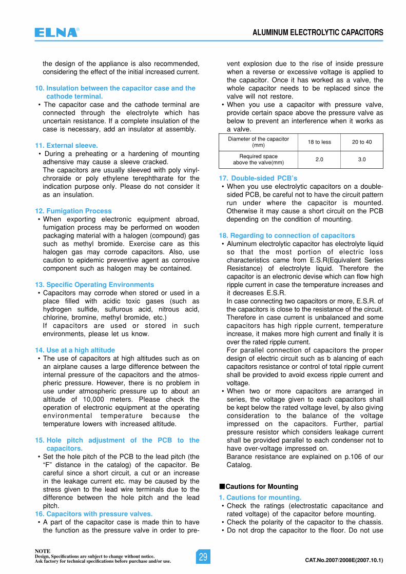
CAT.No.2006/2007E(2006.10.1)25NOTEDesign, Specifications are subject to change without notice.Ask factory for technical specifications before purchase and/or use.
ALUMINUM ELECTROLYTIC CAPACITORS
the design of the appliance is also recommended,considering the effect of the initial increased current.
10. Insulation between the capacitor case and thecathode terminal.
• The capacitor case and the cathode terminal areconnected through the electrolyte which hasuncertain resistance. If a complete insulation of thecase is necessary, add an insulator at assembly.
11. External sleeve. • During a preheating or a hardening of mounting
adhensive may cause a sleeve cracked.The capacitors are usually sleeved with poly vinyl-chroraide or poly ethylene terephtharate for theindication purpose only. Please do not consider itas an insulation.
12. Fumigation Process• When exporting electronic equipment abroad,
fumigation process may be performed on woodenpackaging material with a halogen (compound) gassuch as methyl bromide. Exercise care as thishalogen gas may corrode capacitors. Also, usecaution to epidemic preventive agent as corrosivecomponent such as halogen may be contained.
13. Specific Operating Environments• Capacitors may corrode when stored or used in a
place filled with acidic toxic gases (such ashydrogen sulfide, sulfurous acid, nitrous acid,chlorine, bromine, methyl bromide, etc.)If capacitors are used or stored in suchenvironments, please let us know.
14. Use at a high altitude• The use of capacitors at high altitudes such as on
an airplane causes a large difference between theinternal pressure of the capacitors and the atmos-pheric pressure. However, there is no problem inuse under atmospheric pressure up to about analtitude of 10,000 meters. Please check theoperation of electronic equipment at the operatingenvironmental temperature because thetemperature lowers with increased altitude.
15. Hole pitch adjustment of the PCB to thecapacitors.
• Set the hole pitch of the PCB to the lead pitch (the“F” distance in the catalog) of the capacitor. Becareful since a short circuit, a cut or an increasein the leakage current etc. may be caused by thestress given to the lead wire terminals due to thedifference between the hole pitch and the leadpitch.
16. Capacitors with pressure valves. • A part of the capacitor case is made thin to have
the function as the pressure valve in order to pre-
vent explosion due to the rise of inside pressurewhen a reverse or excessive voltage is applied tothe capacitor. Once it has worked as a valve, thewhole capacitor needs to be replaced since thevalve will not restore.
• When you use a capacitor with pressure valve,provide certain space above the pressure valve asbelow to prevent an interference when it works asa valve.
17. Double-sided PCB’s• When you use electrolytic capacitors on a double-
sided PCB, be careful not to have the circuit patternrun under where the capacitor is mounted.Otherwise it may cause a short circuit on the PCBdepending on the condition of mounting.
18. Regarding to connection of capacitors• Aluminum electrolytic capacitor has electrolyte liquid
so that the most portion of electric losscharacteristics came from E.S.R(Equivalent SeriesResistance) of electrolyte liquid. Therefore thecapacitor is an electronic devise which can flow highripple current in case the temperature increases andit decreases E.S.R.In case connecting two capacitors or more, E.S.R. ofthe capacitors is close to the resistance of the circuit.Therefore in case current is unbalanced and somecapacitors has high ripple current, temperatureincrease, it makes more high current and finally it isover the rated ripple current.For parallel connection of capacitors the properdesign of electric circuit such as b alancing of eachcapacitors resistance or control of total ripple currentshall be provided to avoid excess ripple current andvoltage.
• When two or more capacitors are arranged inseries, the voltage given to each capacitors shallbe kept below the rated voltage level, by also givingconsideration to the balance of the voltageimpressed on the capacitors. Further, partialpressure resistor which considers leakage currentshall be provided parallel to each condenser not tohave over-voltage impressed on.Barance resistance are explained on p.106 of ourCatalog.
1. Cautions for mounting.• Check the ratings (electrostatic capacitance and
rated voltage) of the capacitor before mounting.• Check the polarity of the capacitor to the chassis.• Do not drop the capacitor to the floor. Do not use
Cautions for Mounting
Diameter of the capacitor(mm)
Required spaceabove the valve(mm)
20 to 40
3.0
18 to less
2.0
®
NOTEDesign, Specifications are subject to change without notice.Ask factory for technical specifications before purchase and/or use. 29 CAT.No.2007/2008E(2007.10.1)
CAT.No.2006/2007E(2006.10.1) 26NOTEDesign, Specifications are subject to change without notice.Ask factory for technical specifications before purchase and/or use.
ALUMINUM ELECTROLYTIC CAPACITORS
the dropped capacitor.• Do not deform the capacitor for mounting.
2. Do not apply excessive pressure to the capaci-tor, its terminals or lead wires.
• Make sure that the contact path of the capacitormeets the hole pitch of the PCB before mounting.
• Transient recovery voltage may be generated in thecapacitor due to dielectric absorption. If required,this voltage can be discharged with a resistor witha value of about 1 k .
• A PCB self-standing (snap-in) type capacitor shouldbe pushed to the end (till there is no space) to thePCB for mounting.
• Do not set the automatic insertion machine to clinchthe capacitor lead wires too strong.
• Pay attention to the impact given by the compo-nent receptacles of the automatic insertion/mount-ing machines and the product checker, and fromthe centering operation.
3. Soldering. • Do not dip the capacitor into melted solder.• The soldering conditions
Chip type: Please refer to 28 to 29 page.small and large type: 260˚C, 10 s (max.)
The preliminary heating and other conditionsdescribed in the catalog or product specifications.
• Do not flux other part than the terminals.• If there is a direct contact between the sleeve of
the capacitor and the printed circuit pattern or ametal part of another component such as a leadwire, it may cause shrinkage of crack.
• When you use the capacitor with its sleeve touch-ing directly to the PCB, excessive solder tempera-ture or excessive soldering time may cause thesleeve to shrink or crack during the heat.
• If the application is for extended use, understandand manage the soldering characteristics to avoidabnormal current caused by a contact failurebetween the capacitor and the PCB.
4. Handling after soldering.• After soldering, do not tilt, push down or twist the
capacitor.• After soldering, do not hold the capacitor as a
handle to carry the PCB.• After soldering, do not hit the capacitor with any
obstacle. If PCB’s are piled up for storage, thecapacitor should not touch another PCB or compo-nent.
5. Cleaning after Soldering• Recommended cleaning method
(1)cleaning solutions:(a) CLEANTHROUGH 710M, 750H, 750L(b) PINEALPHA ST-100S(c) Techno Care FRW-4~17(d) Isopropyl alcohol (2-propanol)
(2)Cleaning conditions:(a) The temperature of cleaning solution shall be
less than 60˚C.(b) Use immersion or ultrasonic waves within two
minutes.(c) After cleaning, capacitors and PCB’s shall
thoroughly be rinsed and dried with hot blastfor more than 10 minutes. The temperature ofsuch breeze should be less than the uppercategory temperature.
(d) After cleaning, do not keep capacitors incleaning solution atmosphere or airtightcontainers.
• During cleaning, control the cleaning solutionagainst contamination.
6. Fixing adhesives and coating materials.• Do not use fixing adhesive or coating material
containing halogen-based solvent.• Before applying the fixing adhesive or the coating
material, make sure that there is no remaining fluxor stains between the PCB and the sealed part ofthe capacitor.
• Before applying the fixing adhesive or the coatingmaterial, make sure that the detergent etc. hasdried up.
• Do not cover the whole surface of the sealed part(terminal side) of the capacitor with the fixing ad-hesive or the coating material.
• Observe the description in the catalog or the prod-uct specifications concerning the thermal stiffeningconditions of the fixing adhesive or the coatingmaterial. (If there is no such description, contactus.) When both discrete and SMT components areon the same PCB, the fixing material for the SMTcomponents may cause crack, tear or shrinkage onthe external sleeve depending on the thermalstiffening condition.
• Recommended fixing adhesives and coatingmaterialsFixing adhesives: Cemedine 210,501,540,545N,DiabondDN83K,DA3288,Bond G103Coating materials: Taffy TF1159,HumiSeal 1B66,1A27NS
1. Do not touch capacitor terminals with bare hands.You may get electric shock or your hand may beburnt. Discharge it with a 1 K resistance before useif necessary.
2. Do not short the capacitor terminals with a con-ductor.
Do not spill conductive solution including acid or alka-line solution on the capacitor.
3. Periodical inspections should be establishedfor the capacitors used in industrial appliances.
• The following items should be checked:
Other Cautions
®
NOTEDesign, Specifications are subject to change without notice.Ask factory for technical specifications before purchase and/or use.30CAT.No.2007/2008E(2007.10.1)
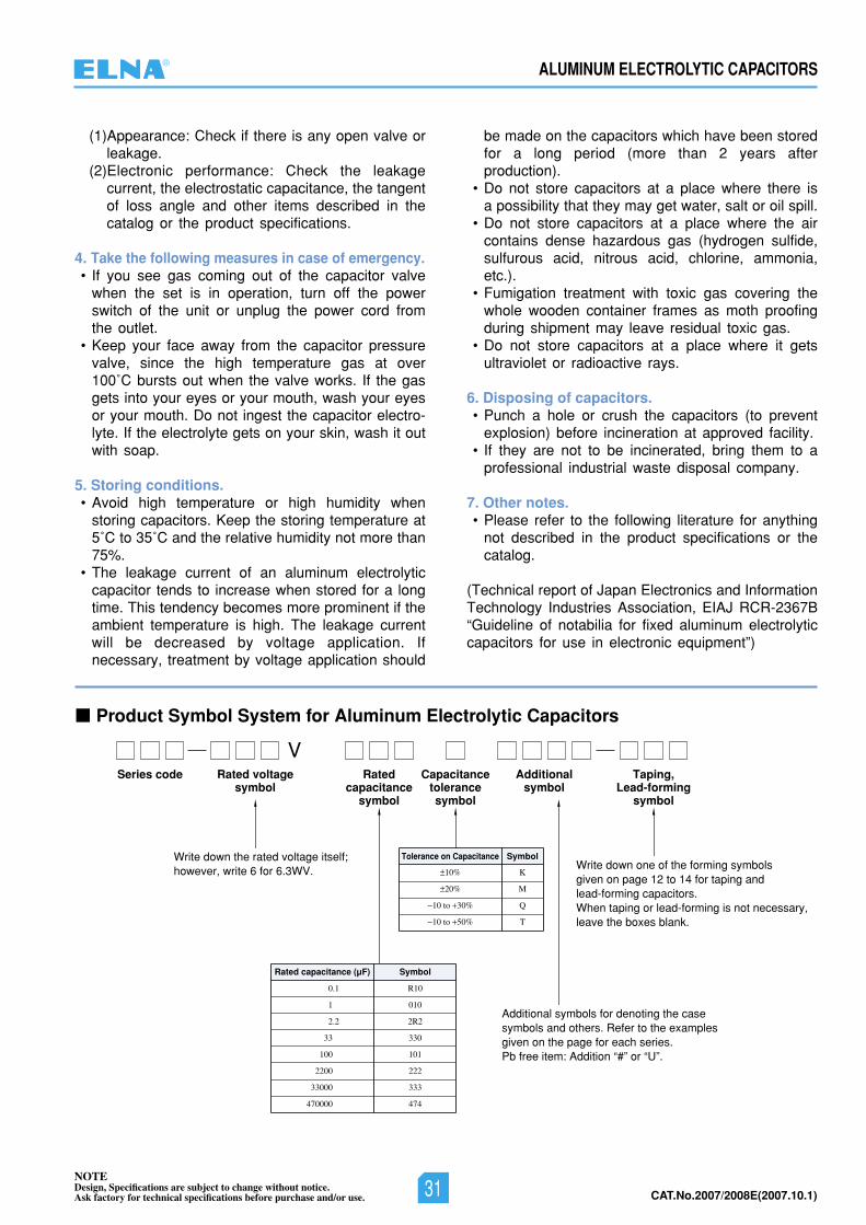
CAT.No.2006/2007E(2006.10.1)27NOTEDesign, Specifications are subject to change without notice.Ask factory for technical specifications before purchase and/or use.
ALUMINUM ELECTROLYTIC CAPACITORS
Product Symbol System for Aluminum Electrolytic Capacitors
Series code Taping,Lead-forming
symbol
Rated voltagesymbol
Ratedcapacitance
symbol
Capacitancetolerancesymbol
Additionalsymbol
Write down the rated voltage itself;however, write 6 for 6.3WV.
V
Additional symbols for denoting the casesymbols and others. Refer to the examplesgiven on the page for each series.Pb free item: Addition “#” or “U”.
Write down one of the forming symbols given on page 12 to 14 for taping and lead-forming capacitors.When taping or lead-forming is not necessary,leave the boxes blank.
10% K
20% M
10 to 30% Q
10 to 50% T
Tolerance on Capacitance Symbol
0.1 R10
1 010
2.2 2R2
33 330
100 101
2200 222
33000 333
470000 474
Rated capacitance (µF) Symbol
(1)Appearance: Check if there is any open valve orleakage.
(2)Electronic performance: Check the leakagecurrent, the electrostatic capacitance, the tangentof loss angle and other items described in thecatalog or the product specifications.
4. Take the following measures in case of emergency.• If you see gas coming out of the capacitor valve
when the set is in operation, turn off the powerswitch of the unit or unplug the power cord fromthe outlet.
• Keep your face away from the capacitor pressurevalve, since the high temperature gas at over100˚C bursts out when the valve works. If the gasgets into your eyes or your mouth, wash your eyesor your mouth. Do not ingest the capacitor electro-lyte. If the electrolyte gets on your skin, wash it outwith soap.
5. Storing conditions.• Avoid high temperature or high humidity when
storing capacitors. Keep the storing temperature at5˚C to 35˚C and the relative humidity not more than75%.
• The leakage current of an aluminum electrolyticcapacitor tends to increase when stored for a longtime. This tendency becomes more prominent if theambient temperature is high. The leakage currentwill be decreased by voltage application. Ifnecessary, treatment by voltage application should
be made on the capacitors which have been storedfor a long period (more than 2 years afterproduction).
• Do not store capacitors at a place where there isa possibility that they may get water, salt or oil spill.
• Do not store capacitors at a place where the aircontains dense hazardous gas (hydrogen sulfide,sulfurous acid, nitrous acid, chlorine, ammonia,etc.).
• Fumigation treatment with toxic gas covering thewhole wooden container frames as moth proofingduring shipment may leave residual toxic gas.
• Do not store capacitors at a place where it getsultraviolet or radioactive rays.
6. Disposing of capacitors.• Punch a hole or crush the capacitors (to prevent
explosion) before incineration at approved facility.• If they are not to be incinerated, bring them to a
professional industrial waste disposal company.
7. Other notes.• Please refer to the following literature for anything
not described in the product specifications or thecatalog.
(Technical report of Japan Electronics and InformationTechnology Industries Association, EIAJ RCR-2367B“Guideline of notabilia for fixed aluminum electrolyticcapacitors for use in electronic equipment”)
®
NOTEDesign, Specifications are subject to change without notice.Ask factory for technical specifications before purchase and/or use. 31 CAT.No.2007/2008E(2007.10.1)
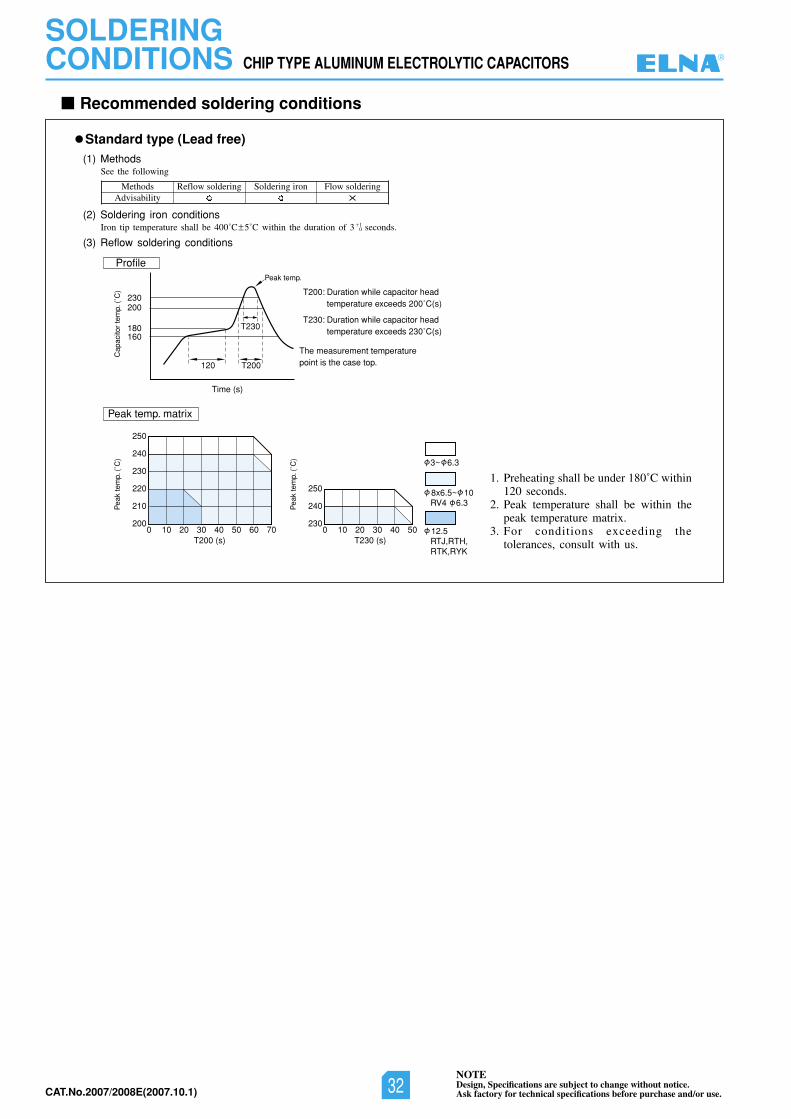
Recommended soldering conditions
(1) MethodsSee the following
(2) Soldering iron conditionsIron tip temperature shall be 400˚C 5˚C within the duration of 3 seconds.
(3) Reflow soldering conditions
Standard type (Lead free)
MethodsAdvisability
Reflow soldering Soldering iron Flow soldering
10
T230
T200
T200: Duration while capacitor head temperature exceeds 200˚C(s)
T230: Duration while capacitor head temperature exceeds 230˚C(s)
The measurement temperaturepoint is the case top.120
Time (s)
160
200
180
230
Cap
acito
r te
mp.
(˚C
)
Peak temp.
Profile
Peak temp. matrix
250
240
230
220
210
2000 10 20 30 40 50 60 70
T200 (s)
Pea
k te
mp.
(˚C
) 3~ 6.3
RV4 6.3 8x6.5~ 10
RTJ,RTH,RTK,RYK
12.5
250
240
2300 10 20 30 40 50
T230 (s)
Pea
k te
mp.
(˚C
)
1. Preheating shall be under 180˚C within120 seconds.
2. Peak temperature shall be within thepeak temperature matrix.
3. For conditions exceeding thetolerances, consult with us.
CHIP TYPE ALUMINUM ELECTROLYTIC CAPACITORS
SOLDERINGCONDITIONS ®
NOTEDesign, Specifications are subject to change without notice.Ask factory for technical specifications before purchase and/or use.32CAT.No.2007/2008E(2007.10.1)
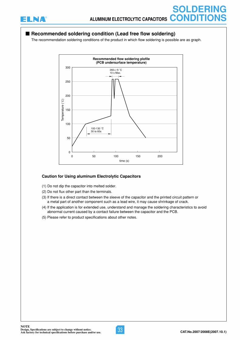
SOLDERINGCONDITIONSALUMINUM ELECTROLYTIC CAPACITORS
0 50 100 150 200
300
250
200
150
100
50
0
time (s)
Recommended flow soldering plofile(PCB undersurface temperature)
100-13030 to 60s
260+/-510 s Max.
Tem
pera
ture
(
)
The recommendation soldering conditions of the product in which flow soldering is possible are as graph.
Recommended soldering condition (Lead free flow soldering)
Caution for Using aluminum Electrolytic Capacitors
(1) Do not dip the capacitor into melted solder.
(2) Do not flux other part than the terminals.
(3) If there is a direct contact between the sleeve of the capacitor and the printed circuit pattern or a metal part of another component such as a lead wire, it may cause shrinkage of crack.
(4) If the application is for extended use, understand and manage the soldering characteristics to avoidabnormal current caused by a contact failure between the capacitor and the PCB.
(5) Please refer to product specifications about other notes.
®
NOTEDesign, Specifications are subject to change without notice.Ask factory for technical specifications before purchase and/or use. 33 CAT.No.2007/2008E(2007.10.1)
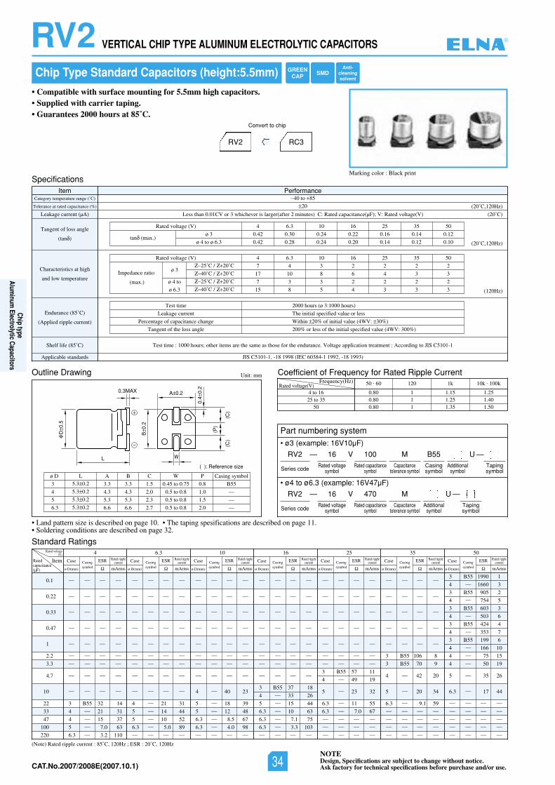
NOTEDesign, Specifications are subject to change without notice.Ask factory for technical specifications before purchase and/or use.CAT.No.2006/2007E(2006.10.1)
RV2 VERTICAL CHIP TYPE ALUMINUM ELECTROLYTIC CAPACITORS
L
D0.
5
B0.
2
(P)
(C)
(C)
0.4
0.2
A 0.2
( ): Reference size
0.3MAX
W
Specifications
Outline Drawing
Standard Ratings
Coefficient of Frequency for Rated Ripple Current
Item PerformanceCategory temperature range (˚C)
Tolerance at rated capacitance (%)
Leakage current (µA)
Tangent of loss angle
(tan )
Characteristics at high
and low temperature
Endurance (85˚C)
(Applied ripple current)
Shelf life (85˚ SIJotgnidroccA:tnemtaertnoitacilppaegatloV.ecnarudneehtrofesohtsaemasehterasmetirehto;sruoh0001:emittseT)C C5101-1
Applicable standards JIS C5101-1, -18 1998 (IEC 60384-1 1992, -18 1993)
40 to 85
20
02()V(egatlovdetaR:V;)Fµ(ecnaticapacdetaR:C)setunim2retfa(regralsirevehcihw3roVC10.0nahtsseL ˚C)
(20˚C,120Hz)
(20˚C,120Hz)
(120Hz)
Test time
Leakage current
Percentage of capacitance change
Tangent of the loss angle
2000 hours (ø 3:1000 hours)
The initial specified value or less
Within 20% of initial value (4WV: 30%)
200% or less of the initial specified value (4WV: 300%)
Unit: mm
Rated voltage(V)Frequency(Hz)
• Land pattern size is described on page 10. • The taping spesifications are described on page 11.• Soldering conditions are described on page 32.
4 to 1625 to 35
50
(Note) Rated ripple current : 85˚C, 120Hz ; ESR : 20˚C, 120Hz
50 . 60 120 1k 10k . 100k
0.80 1 1.15 1.250.80 1 1.25 1.400.80 1 1.35 1.50
• ø3 (example: 16V10µF)
• ø4 to ø6.3 (example: 16V47µF)
0.1
0.22
0.33
0.47
1
2.2
3.3
4.7
10
22
33
47
100
220
6.3 05535261014
Item
— — — —
— — — —
— — — —
— — — —
— — — —
— — — —
— — — —
— — — —
— — — —
3 B55 32 14
4 — 21 31
4 — 15 37
5 — 7.0 63
6.3 — 3.2 110
— — — —
— — — —
— — — —
— — — —
— — — —
— — — —
— — — —
— — — —
— — — —
4 — 21 31
5 — 14 44
5 — 10 52
6.3 — 5.0 89— — — —
— — — —
— — — —
— — — —
— — — —
— — — —
— — — —
— — — —
— — — —
4 — 40 23
5 — 18 39
5 — 12 48
6.3 — 8.5 67
6.3 — 4.0 98— — — —
— — — —
— — — —
— — — —
— — — —
— — — —
— — — —
— — — —
— — — —
3 B55 37 18
4 — 33 26
5 — 15 44
6.3 — 10 63
6.3 — 7.1 75
6.3 — 3.3 103— — — —
— — — —
— — — —
— — — —
— — — —
— — — —
— — — —
— — — —
3 B55 57 11
4 — 49 19
5 — 23 32
6.3 — 11 55
6.3 — 7.0 67— — — —
— — — —
— — — —
— — — —
— — — —
— — — —
— — — —
— — — —
3 B55 106 8
3 B55 70 9
4 — 42 20
5 — 20 34
6.3 — 9.1 59— — — —
— — — —
— — — —
— — — —
3 B55 1990 1
4 — 1660 3
3 B55 905 2
4 — 754 5
3 B55 603 3
4 — 503 6
3 B55 424 4
4 — 353 7
3 B55 199 6
4 — 166 10
4 — 75 15
4 — 50 19
5 — 35 26
6.3 — 17 44
— — — —
— — — —
— — — —
— — — —
— — — —
Case
ø D(mm)
ESR
mArms
Rated ripplecurrent
3
4
5
6.3
ø D5.3 0.2
5.3 0.2
5.3 0.2
5.3 0.2
L
3.3
4.3
5.3
6.6
A
3.3
4.3
5.3
6.6
B
1.5
2.0
2.3
2.7
C
0.45 to 0.75
0.5 to 0.8
0.5 to 0.8
0.5 to 0.8
W
0.8
1.0
1.5
2.0
B55
—
—
—
P Casing symbol
05535261013.64)V(egatlovdetaR
0.42 0.30 0.24 0.22 0.16 0.14 0.12
0.42 0.28 0.24 0.20 0.14 0.12 0.10
Chip Type Standard Capacitors (height:5.5mm)
• Compatible with surface mounting for 5.5mm high capacitors.• Supplied with carrier taping.• Guarantees 2000 hours at 85˚C.
Marking color : Black print
RV2 RC3
Convert to chip
tan (max.)ø 3
ø 4 to ø 6.3
ø 3
ø 4 to
ø 6.3
05535261013.64)V(egatlovdetaR
7 4 3 2 2 2 2
17 10 8 6 4 3 3
7 3 3 2 2 2 2
15 8 5 4 3 3 3
Impedance ratio
(max.)
25˚C / 20˚C
40˚C / 20˚C
25˚C / 20˚C
40˚C / 20˚C
Casingsymbol
Case
ø D(mm)
ESR
mArms
Rated ripplecurrentCasing
symbol
Case
ø D(mm)
ESR
mArms
Rated ripplecurrentCasing
symbol
Case
ø D(mm)
ESR
mArms
Rated ripplecurrentCasing
symbol
Case
ø D(mm)
ESR
mArms
Rated ripplecurrentCasing
symbol
Case
ø D(mm)
ESR
mArms
Rated ripplecurrentCasing
symbol
Case
ø D(mm)
ESR
mArms
Rated ripplecurrentCasing
symbol
Rated voltage(V)
Ratedcapacitance(µF)
Part numbering system
RV2 — V
Series code
16 100 MRated voltage
symbolRated capacitance
symbolCapacitance
tolerance symbol
B55Casingsymbol
—Tapingsymbol
Additionalsymbol
U
RV2 — V
Series code
16 470 MRated voltage
symbolRated capacitance
symbolCapacitance
tolerance symbol
—Tapingsymbol
Additionalsymbol
U
GREENCAP SMD
Anti-cleaningsolvent
®
Chip typeAlum
inum Electrolytic Capacitors
NOTEDesign, Specifications are subject to change without notice.Ask factory for technical specifications before purchase and/or use.34CAT.No.2007/2008E(2007.10.1)
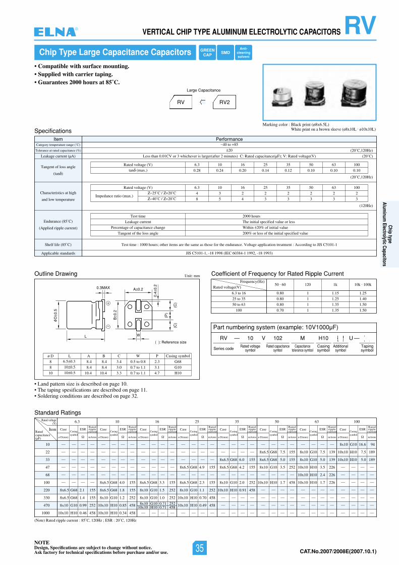
NOTEDesign, Specifications are subject to change without notice.Ask factory for technical specifications before purchase and/or use. CAT.No.2006/2007E(2006.10.1)
L
D0.
5
B0.
2
(P)
(C)
(C)
0.4
0.2
A 0.2
( ): Reference size
0.3MAX
W
Chip Type Large Capacitance Capacitors
• Compatible with surface mounting.• Supplied with carrier taping.• Guarantees 2000 hours at 85˚C.
Marking color : Black print (ø8x6.5L)White print on a brown sleeve (ø8x10L . ø10x10L)
RV RV2
Large Capacitance
Outline Drawing
Standard Ratings
Unit: mm
• Land pattern size is described on page 10.• The taping spesifications are described on page 11.• Soldering conditions are described on page 32.
(Note) Rated ripple current : 85˚C, 120Hz ; ESR : 20˚C, 120Hz
10
22
33
47
68
100
220
330
470
1000
Rated voltage(V) 6.3
ItemRatedcapacitance(µF)
— — — —
— — — —
— — — —
— — — —
— — — —
— — — —
8x6.5 G68 2.1 155
8x6.5 G68 1.4 155
8x10 G10 0.99 252
10x10 H10 0.46 458
Case
ø D(mm)
Casingsymbol
ESR
mArms
8
8
10
ø D6.5 0.3
10 0.5
10 0.5
L
8.4
8.4
10.4
A
8.4
8.4
10.4
B
3.4
3.0
3.3
C
0.5 to 0.8
0.7 to 1.1
0.7 to 1.1
W
G68
G10
H10
Casing symbol
2.3
3.1
4.7
P
SpecificationsItem Performance
Category temperature range (˚C)
Tolerance at rated capacitance (%)
Leakage current (µA)
Tangent of loss angle
(tan )
Characteristics at high
and low temperature
Endurance (85˚C)
(Applied ripple current)
Shelf life (85˚ SIJotgnidroccA:tnemtaertnoitacilppaegatloV.ecnarudneehtrofesohtsaemasehterasmetirehto;sruoh0001:emittseT)C C5101-1
Applicable standards JIS C5101-1, -18 1998 (IEC 60384-1 1992, -18 1993)
40 to 85
20
Less than 0.01CV or 3 whichever is larger(after 2 minutes) C: Rated capacitance(µF); V: Rated voltage(V)
0013605535261013.6)V(egatlovdetaR
0.28 0.24 0.20 0.14 0.12 0.10 0.10 0.10tan (max.)
(20˚C)
(20˚C,120Hz)
(20˚C,120Hz)
(120Hz)
Test time
Leakage current
Percentage of capacitance change
Tangent of the loss angle
2000 hours
The initial specified value or less
Within 20% of initial value
200% or less of the initial specified value
0013605535261013.6)V(egatlovdetaR
4 3 2 2 2 2 2 2
8 5 4 3 3 3 3 3Impedance ratio (max.)
25˚C / 20˚C
40˚C / 20˚C
Coefficient of Frequency for Rated Ripple Current
Rated voltage(V)
Frequency(Hz)
6.3 to 16
25 to 35
50 to 63
100
50 . 60 120 1k 10k . 100k
0.80 1 1.15 1.25
0.80 1 1.25 1.40
0.80 1 1.35 1.50
0.70 1 1.35 1.50
Part numbering system (example: 10V1000µF)
Ratedripplecurrent
10
— — — —
— — — —
— — — —
— — — —
— — — —
8x6.5 G68 4.0 155
8x6.5 G68 1.8 155
8x10 G10 1.2 252
10x10 H10 0.85 458
10x10 H10 0.34 458
Case
ø D(mm)
Casingsymbol
ESR
mArms
Ratedripplecurrent
16
— — — —
— — — —
— — — —
— — — —
— — — —
8x6.5 G68 3.3 155
8x10 G10 1.5 252
8x10 G10 1.0 252
— — — —
8x10 G10 0.71 25210x10 H10 0.71 458
Case
ø D(mm)
Casingsymbol
ESR
mArms
Ratedripplecurrent
25
— — — —
— — — —
— — — —
8x6.5 G68 4.9 155
— — — —
8x6.5 G68 2.3 155
8x10 G10 1.1 252
10x10 H10 0.70 458
10x10 H10 0.49 458
— — — —
Case
ø D(mm)
Casingsymbol
ESR
mArms
Ratedripplecurrent
35
— — — —
— — — —
8x6.5 G68 6.0 155
8x6.5 G68 4.2 155
— — — —
8x10 G10 2.0 252
10x10 H10 0.91 458
— — — —
— — — —
— — — —
Case
ø D(mm)
Casingsymbol
ESR
mArms
Ratedripplecurrent
50
— — — —
8x6.5 G68 7.5 155
8x6.5 G68 5.0 155
8x10 G10 3.5 252
— — — —
10x10 H10 1.7 458
— — — —
— — — —
— — — —
— — — —
Case
ø D(mm)
Casingsymbol
ESR
mArms
Ratedripplecurrent
63
— — — —
8x10 G10 7.5 139
8x10 G10 5.0 139
10x10 H10 3.5 226
10x10 H10 2.4 226
10x10 H10 1.7 226
— — — —
— — — —
— — — —
— — — —
Case
ø D(mm)
Casingsymbol
ESR
mArms
Ratedripplecurrent
100
8x10 G10 16.6 94
10x10 H10 7.5 189
10x10 H10 5.0 189
— — — —
— — — —
— — — —
— — — —
— — — —
— — — —
— — — —
Case
ø D(mm)
Casingsymbol
ESR
mArms
Ratedripplecurrent
RVVERTICAL CHIP TYPE ALUMINUM ELECTROLYTIC CAPACITORS
RV — V
Series code
10 102 MRated voltage
symbolRated capacitance
symbolCapacitance
tolerance symbol
H10Casingsymbol
—Tapingsymbol
Additionalsymbol
U
GREENCAP SMD
Anti-cleaningsolvent
®
Chip typeAlum
inum Electrolytic Capacitors
NOTEDesign, Specifications are subject to change without notice.Ask factory for technical specifications before purchase and/or use. 35 CAT.No.2007/2008E(2007.10.1)
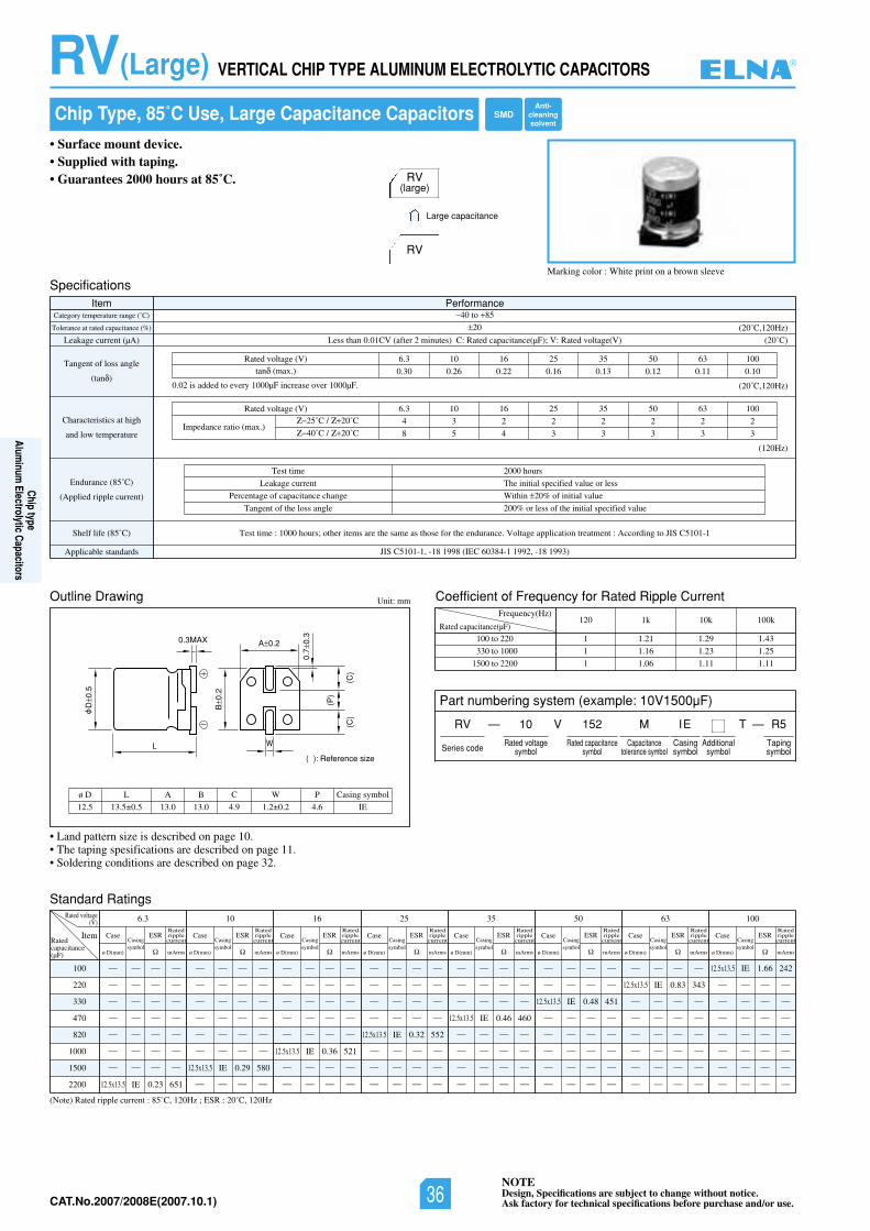
NOTEDesign, Specifications are subject to change without notice.Ask factory for technical specifications before purchase and/or use.CAT.No.2006/2007E(2006.10.1)
• Land pattern size is described on page 10.• The taping spesifications are described on page 11.• Soldering conditions are described on page 32.
Chip Type, 85˚C Use, Large Capacitance Capacitors
• Surface mount device.• Supplied with taping.• Guarantees 2000 hours at 85˚C.
Marking color : White print on a brown sleeve
Specifications
Outline Drawing
Item PerformanceCategory temperature range (˚C)
Tolerance at rated capacitance (%)
Leakage current (µA)
Tangent of loss angle
(tan )
Characteristics at high
and low temperature
Endurance (85˚C)
(Applied ripple current)
Shelf life (85˚ SIJotgnidroccA:tnemtaertnoitacilppaegatloV.ecnarudneehtrofesohtsaemasehterasmetirehto;sruoh0001:emittseT)C C5101-1
Applicable standards JIS C5101-1, -18 1998 (IEC 60384-1 1992, -18 1993)
40 to 85
20
02()V(egatlovdetaR:V;)Fµ(ecnaticapacdetaR:C)setunim2retfa(VC10.0nahtsseL ˚C)
(20˚C,120Hz)
Test time
Leakage current
Percentage of capacitance change
Tangent of the loss angle
2000 hours
The initial specified value or less
Within 20% of initial value
200% or less of the initial specified value
Unit: mm
Part numbering system (example: 10V1500µF)
— VRV
Series code
10
Rated voltagesymbol
152
Rated capacitancesymbol
M
Capacitancetolerance symbol
IE
Casingsymbol
—T R5
Tapingsymbol
RV(large)
RV
Large capacitance
0013605535261013.6)V(egatlovdetaR
0.30 0.26 0.22 0.16 0.13 0.12 0.11 0.10tan (max.)
(20˚C,120Hz)
(120Hz)
0013605535261013.6)V(egatlovdetaR
4 3 2 2 2 2 2 2
8 5 4 3 3 3 3 3Impedance ratio (max.)
25˚C / 20˚C
40˚C / 20˚C
0.02 is added to every 1000µF increase over 1000µF.
Standard Ratings
(Note) Rated ripple current : 85˚C, 120Hz ; ESR : 20˚C, 120Hz
100
220
330
470
820
1000
1500
2200
Rated voltage(V) 6.3
ItemRatedcapacitance(µF)
— — — —
— — — —
— — — —
— — — —
— — — —
— — — —
— — — —
12.5x13.5 IE 0.23 651
Case
ø D(mm)
Casingsymbol
ESR
mArms
Ratedripplecurrent
10
— — — —
— — — —
— — — —
— — — —
— — — —
— — — —
12.5x13.5 IE 0.29 580
— — — —
— — — —
— — — —
— — — —
— — — —
12.5x13.5 IE 0.36 521
— — — —
— — — —
— — — —
— — — —
— — — —
— — — —
12.5x13.5 IE 0.32 552
— — — —
— — — —— — — —
— — — —
— — — —
12.5x13.5 IE 0.48 451
— — — —
— — — —
— — — —
— — — —
— — — —
12.5x13.5 IE 0.83 343
— — — —
— — — —
— — — —
— — — —
— — — —
12.5x13.5 IE 1.66 242
— — — —
— — — —— — — —
— — — —— — — —
— — — —
— — — —
— — — —
— — — —
— — — —
— — — —
— — — —
12.5x13.5 IE 0.46 460
— — — —
— — — —— — — —
— — — —
— — — —
Case
ø D(mm)
Casingsymbol
ESR
mArms
Ratedripplecurrent
16
Case
ø D(mm)
Casingsymbol
ESR
mArms
Ratedripplecurrent
25
Case
ø D(mm)
Casingsymbol
ESR
mArms
Ratedripplecurrent
35
Case
ø D(mm)
Casingsymbol
ESR
mArms
Ratedripplecurrent
50
Case
ø D(mm)
Casingsymbol
ESR
mArms
Ratedripplecurrent
63
Case
ø D(mm)
Casingsymbol
ESR
mArms
Ratedripplecurrent
100
Case
ø D(mm)
Casingsymbol
ESR
mArms
Ratedripplecurrent
Coefficient of Frequency for Rated Ripple Current
Rated capacitance(µF)
Frequency(Hz)
100 to 220
330 to 1000
1500 to 2200
120 1k 10k 100k
1 1.21 1.29 1.43
1 1.16 1.23 1.25
1 1.06 1.11 1.11
L
D0.
5
B0.
2
(C)
(P)
(C)
0.7
0.3
A 0.2
( ): Reference size
0.3MAX
W
12.5
ø D
13.5±0.5
L
13.0 13.0
A B
4.9
C
1.2±0.2
W
4.6 IE
P Casing symbol
RV(Large) VERTICAL CHIP TYPE ALUMINUM ELECTROLYTIC CAPACITORS
SMDAnti-
cleaningsolvent
Additionalsymbol
®
Chip typeAlum
inum Electrolytic Capacitors
NOTEDesign, Specifications are subject to change without notice.Ask factory for technical specifications before purchase and/or use.36CAT.No.2007/2008E(2007.10.1)
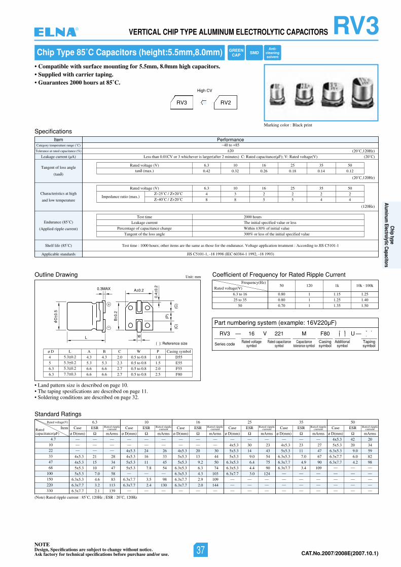
NOTEDesign, Specifications are subject to change without notice.Ask factory for technical specifications before purchase and/or use. CAT.No.2006/2007E(2006.10.1)
RV3VERTICAL CHIP TYPE ALUMINUM ELECTROLYTIC CAPACITORS
Chip Type 85˚C Capacitors (height:5.5mm,8.0mm)
• Compatible with surface mounting for 5.5mm, 8.0mm high capacitors.• Supplied with carrier taping.• Guarantees 2000 hours at 85˚C.
Marking color : Black print
RV3 RV2
High CV
L
D0.
5
B0.
2
(P)
(C)
(C)
0.4
0.2
A 0.2
( ): Reference size
0.3MAX
W
Specifications
Outline Drawing
Standard Ratings
Coefficient of Frequency for Rated Ripple Current
Item PerformanceCategory temperature range (˚C)
Tolerance at rated capacitance (%)
Leakage current (µA)
Tangent of loss angle
(tan )
Characteristics at high
and low temperature
Endurance (85˚C)
(Applied ripple current)
Shelf life (85˚ SIJotgnidroccA:tnemtaertnoitacilppaegatloV.ecnarudneehtrofesohtsaemasehterasmetirehto;sruoh0001:emittseT)C C5101-1
Applicable standards JIS C5101-1, -18 1998 (IEC 60384-1 1992, -18 1993)
40 to 85
20
Less than 0.01CV or 3 whichever is larger(after 2 minutes) C: Rated capacitance(µF); V: Rated voltage(V)
05535261013.6)V(egatlovdetaR
0.42 0.32 0.26 0.18 0.14 0.12tan (max.)
(20˚C)
(20˚C,120Hz)
(20˚C,120Hz)
(120Hz)
Test time
Leakage current
Percentage of capacitance change
Tangent of the loss angle
2000 hours
The initial specified value or less
Within 30% of initial value
300% or less of the initial specified value
05535261013.6)V(egatlovdetaR
4 3 2 2 2 2
8 8 5 5 4 4Impedance ratio (max.)
25˚C / 20˚C
40˚C / 20˚C
Unit: mm
Rated voltage(V)
Frequency(Hz)
6.3 to 16
25 to 35
50
(Note) Rated ripple current : 85˚C, 120Hz ; ESR : 20˚C, 120Hz
50 120 1k 10k . 100k
0.80 1 1.15 1.25
0.80 1 1.25 1.40
0.70 1 1.35 1.50
4.7
10
22
33
47
68
100
150
220
330
Rated voltage(V) 05535261013.6
ItemRatedcapacitance(µF)
— — —
— — —
— — —
4x5.3 21 28
4x5.3 15 34
5x5.3 10 47
5x5.3 7.0 58
6.3x5.3 4.6 83
6.3x7.7 3.2 113
6.3x7.7 2.1 139
— — —
— — —
4x5.3 24 26
4x5.3 16 33
5x5.3 11 45
5x5.3 7.8 54— — —
6.3x7.7 3.5 98
6.3x7.7 2.4 130— — —
— — —
— — —
4x5.3 20 30
5x5.3 13 44
5x5.3 9.2 50
6.3x5.3 6.3 74
6.3x5.3 4.3 103
6.3x7.7 2.9 109
6.3x7.7 2.0 144— — —
— — —
4x5.3 30 23
5x5.3 14 43
5x5.3 9.0 54
6.3x5.3 6.4 75
6.3x5.3 4.4 90
6.3x7.7 3.0 124— — —
— — —
— — —
— — —
4x5.3 23 27
5x5.3 11 47
6.3x5.3 7.0 67
6.3x7.7 4.9 90
6.3x7.7 3.4 109— — —
— — —
— — —
— — —
4x5.3 42 20
5x5.3 20 34
6.3x5.3 9.0 59
6.3x7.7 6.0 82
6.3x7.7 4.2 98— — —
— — —
— — —
— — —
— — —
Case ESR
ø D(mm) mArms
Rated ripplecurrent Case ESR
ø D(mm) mArms
Rated ripplecurrent Case ESR
ø D(mm) mArms
Rated ripplecurrent Case ESR
ø D(mm) mArms
Rated ripplecurrent Case ESR
ø D(mm) mArms
Rated ripplecurrent Case ESR
ø D(mm) mArms
Rated ripplecurrent
4
5
6.3
6.3
ø D5.3 0.2
5.3 0.2
5.3 0.2
7.7 0.3
L
4.3
5.3
6.6
6.6
A
4.3
5.3
6.6
6.6
B
2.0
2.3
2.7
2.7
C
0.5 to 0.8
0.5 to 0.8
0.5 to 0.8
0.5 to 0.8
W
1.0
1.5
2.0
2.5
D55
E55
F55
F80
P Casing symbol
• Land pattern size is described on page 10.• The taping spesifications are described on page 11.• Soldering conditions are described on page 32.
Part numbering system (example: 16V220µF)
RV3 — V
Series code
16 221 MRated voltage
symbolRated capacitance
symbolCapacitance
tolerance symbol
F80Casingsymbol
—Tapingsymbol
Additionalsymbol
U
GREENCAP SMD
Anti-cleaningsolvent
®
Chip typeAlum
inum Electrolytic Capacitors
NOTEDesign, Specifications are subject to change without notice.Ask factory for technical specifications before purchase and/or use. 37 CAT.No.2007/2008E(2007.10.1)
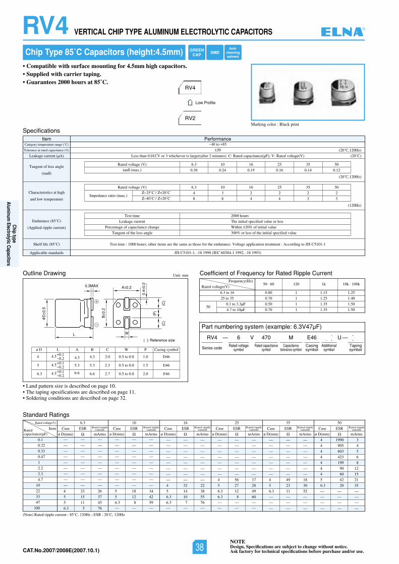
NOTEDesign, Specifications are subject to change without notice.Ask factory for technical specifications before purchase and/or use.CAT.No.2006/2007E(2006.10.1)
RV4 VERTICAL CHIP TYPE ALUMINUM ELECTROLYTIC CAPACITORS
L
D0.
5
B0.
2
(P)
(C)
(C)
0.4
0.2
A 0.2
( ): Reference size
0.3MAX
W
Chip Type 85˚C Capacitors (height:4.5mm)
• Compatible with surface mounting for 4.5mm high capacitors.• Supplied with carrier taping.• Guarantees 2000 hours at 85˚C.
Marking color : Black print
RV4
RV2
Low Profile
Specifications
Outline Drawing
Standard Ratings
Coefficient of Frequency for Rated Ripple Current
Item PerformanceCategory temperature range (˚C)
Tolerance at rated capacitance (%)
Leakage current (µA)
Tangent of loss angle
(tan )
Characteristics at high
and low temperature
Endurance (85˚C)
(Applied ripple current)
Shelf life (85˚ SIJotgnidroccA:tnemtaertnoitacilppaegatloV.ecnarudneehtrofesohtsaemasehterasmetirehto;sruoh0001:emittseT)C C5101-1
Applicable standards JIS C5101-1, -18 1998 (IEC 60384-1 1992, -18 1993)
40 to 85
20
Less than 0.01CV or 3 whichever is larger(after 2 minutes) C: Rated capacitance(µF); V: Rated voltage(V)
05535261013.6)V(egatlovdetaR
0.30 0.24 0.19 0.16 0.14 0.12tan (max.)
(20˚C)
(20˚C,120Hz)
(20˚C,120Hz)
(120Hz)
Test time
Leakage current
Percentage of capacitance change
Tangent of the loss angle
2000 hours
The initial specified value or less
Within 20% of initial value
300% or less of the initial specified value
05535261013.6)V(egatlovdetaR
4 3 2 2 2 2
8 8 4 4 3 3Impedance ratio (max.)
25˚C / 20˚C
40˚C / 20˚C
Unit: mm
Rated voltage(V)
Frequency(Hz)
6.3 to 16
25 to 35
0.1 to 3.3µF
4.7 to 10µF50
(Note) Rated ripple current : 85˚C, 120Hz ; ESR : 20˚C, 120Hz
50 . 60 120 1k 10k . 100k
0.80 1 1.15 1.25
0.70 1 1.25 1.40
0.50 1 1.35 1.50
0.70 1 1.35 1.50
0.1
0.22
0.33
0.47
1
2.2
3.3
4.7
10
22
33
47
100
Rated voltage(V) 05535261013.6
ItemRatedcapacitance(µF)
— — —
— — —
— — —
— — —
— — —
— — —
— — —
— — —
— — —
4 23 26
5 15 37
5 11 45
6.3 5 76
— — —
— — —
— — —
— — —
— — —
— — —
— — —
— — —
— — —
5 18 34
5 12 42
6.3 8 59— — —
— — —
— — —
— — —
— — —
— — —
— — —
— — —
— — —
4 32 22
5 14 38
6.3 10 55
6.3 7 76— — —
— — —
— — —
— — —
— — —
— — —
— — —
— — —
4 56 17
5 27 28
6.3 12 49
6.3 8 60
— — —— — —
— — —
— — —
— — —
— — —
— — —
— — —
— — —
4 49 18
5 23 30
6.3 11 52
— — —
— — —
— — —
4 1990 3
4 905 4
4 603 5
4 423 6
4 199 8
4 90 12
4 60 15
5 42 21
6.3 20 35
— — —
— — —
— — —
— — —
Case ESR
ø D(mm) mArms
Rated ripplecurrent Case ESR
ø D(mm) mArms
Rated ripplecurrent Case ESR
ø D(mm) mArms
Rated ripplecurrent Case ESR
ø D(mm) mArms
Rated ripplecurrent Case ESR
ø D(mm) mArms
Rated ripplecurrent Case ESR
ø D(mm) mArms
Rated ripplecurrent
4
5
6.3
ø D
4.5 0.10.2
4.5 0.10.2
4.5 0.10.2
L
4.3
5.3
6.6
A
4.3
5.3
6.6
B
2.0
2.3
2.7
C
0.5 to 0.8
0.5 to 0.8
0.5 to 0.8
W
1.0
1.5
2.0
D46
E46
F46
P Casing symbol
• Land pattern size is described on page 10.• The taping spesifications are described on page 11.• Soldering conditions are described on page 32.
Part numbering system (example: 6.3V47µF)
RV4 — V
Series code
6 470 MRated voltage
symbolRated capacitance
symbolCapacitance
tolerance symbol
E46Casingsymbol
—Tapingsymbol
Additionalsymbol
U
GREENCAP SMD
Anti-cleaningsolvent
®
Chip typeAlum
inum Electrolytic Capacitors
NOTEDesign, Specifications are subject to change without notice.Ask factory for technical specifications before purchase and/or use.38CAT.No.2007/2008E(2007.10.1)
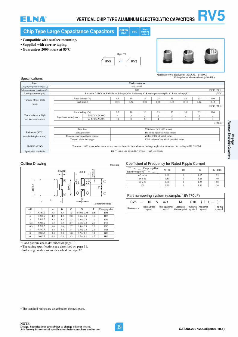
NOTEDesign, Specifications are subject to change without notice.Ask factory for technical specifications before purchase and/or use. CAT.No.2006/2007E(2006.10.1)
RV5VERTICAL CHIP TYPE ALUMINUM ELECTROLYTIC CAPACITORS
• Land pattern size is described on page 10.• The taping spesifications are described on page 11.• Soldering conditions are described on page 32.
Chip Type Large Capacitance Capacitors
• Compatible with surface mounting.• Supplied with carrier taping.• Guarantees 2000 hours at 85˚C.
Marking color : Black print (ø3x5.3L – ø8x10L)White print on a brown sleeve (ø10x10L)
RV5 RV3
High CV
Outline Drawing Unit: mm
SpecificationsItem Performance
Category temperature range (˚C)
Tolerance at rated capacitance (%)
Leakage current (µA)
Tangent of loss angle
(tan )
Endurance (85˚C)
(Applied ripple current)
Shelf life (85˚ SIJotgnidroccA:tnemtaertnoitacilppaegatloV.ecnarudneehtrofesohtsaemasehterasmetirehto;sruoh0001:emittseT)C C5101-1
Applicable standards JIS C5101-1, -18 1998 (IEC 60384-1 1992, -18 1993)
40 to 85
20
Less than 0.01CV or 3 whichever is larger(after 2 minutes) C: Rated capacitance(µF); V: Rated voltage(V)
0013605535261013.6)V(egatlovdetaR
0.35 0.32 0.28 0.18 0.14 0.12 0.12 0.12tan (max.)
(20˚C)
(20˚C,120Hz)
(20˚C,120Hz)
Test time
Leakage current
Percentage of capacitance change
Tangent of the loss angle
2000 hours (ø 3:1000 hours)
The initial specified value or less
Within 30% of initial value
300% or less of the initial specified value
Coefficient of Frequency for Rated Ripple Current
Rated voltage(V)
Frequency(Hz)
6.3 to 16
25 to 35
50 to 63
100
50 . 60 120 1k 10k . 100k
0.80 1 1.15 1.25
0.80 1 1.25 1.40
0.80 1 1.35 1.50
0.70 1 1.35 1.50
L
D0.
5
B0.
2
(P)
(C)
(C)
0.4
0.2
A 0.2
( ): Reference size
0.3MAX
W
3
4
5
6.3
6.3
8
8
10
ø D5.3 0.2
5.3 0.2
5.3 0.2
5.3 0.2
7.7 0.3
6.5 0.3
10 0.5
10 0.5
L
3.3
4.3
5.3
6.3
6.6
8.4
8.4
10.4
3.3
4.3
5.3
6.3
6.6
8.4
8.4
10.4
A B
1.5
2.0
2.3
2.7
2.7
3.4
3.0
3.3
C
0.45 to 0.75
0.5 to 0.8
0.5 to 0.8
0.5 to 0.8
0.5 to 0.8
0.5 to 0.8
0.7 to 1.1
0.7 to 1.1
W
B55
D55
E55
F55
F80
G68
G10
H10
Casing symbol
0.8
1.0
1.5
2.0
2.0
2.3
3.1
4.7
P
Characteristics at high
and low temperature
(120Hz)
0013605535261013.6)V(egatlovdetaR
4 3 2 2 2 2 2 2
10 8 6 4 3 3 3 3Impedance ratio (max.)
25˚C / 20˚C
40˚C / 20˚C
Part numbering system (example: 16V470µF)
RV5 — V
Series code
16 471 MRated voltage
symbolRated capacitance
symbolCapacitance
tolerance symbol
G10Casingsymbol
—Tapingsymbol
Additionalsymbol
U
• The standard ratings are described on the next page.
GREENCAP SMD
Anti-cleaningsolvent
®
Chip typeAlum
inum Electrolytic Capacitors
NOTEDesign, Specifications are subject to change without notice.Ask factory for technical specifications before purchase and/or use. 39 CAT.No.2007/2008E(2007.10.1)
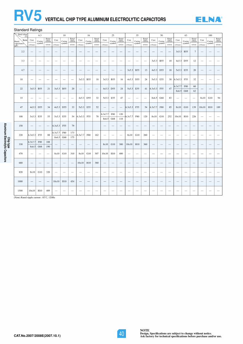
NOTEDesign, Specifications are subject to change without notice.Ask factory for technical specifications before purchase and/or use.CAT.No.2006/2007E(2006.10.1)
RV5 VERTICAL CHIP TYPE ALUMINUM ELECTROLYTIC CAPACITORS
Standard Ratings
(Note) Rated ripple current : 85˚C, 120Hz
2.2
3.3
4.7
10
22
33
47
100
150
220
330
470
680
820
1000
1500
Rated voltage(V) 6.3
ItemRatedcapacitance(µF)
— — —
— — —
— — —
— — —
3x5.3 B55 21
— — —
4x5.3 D55 34
5x5.3 E55 55
— — —
6.3x5.3 F55 88
6.3x7.7 F80 188
8x6.5 G68 190
— — —
— — —
8x10 G10 320
— — —
10x10 H10 489
Case
ø D(mm)
Casingsymbol
mArms
Ratedripplecurrent
Case
ø D(mm)
Casingsymbol
mArms
Ratedripplecurrent
Case
ø D(mm)
Casingsymbol
mArms
Ratedripplecurrent
Case
ø D(mm)
Casingsymbol
mArms
Ratedripplecurrent
Case
ø D(mm)
Casingsymbol
mArms
Ratedripplecurrent
Case
ø D(mm)
Casingsymbol
mArms
Ratedripplecurrent
Case
ø D(mm)
Casingsymbol
mArms
Ratedripplecurrent
Case
ø D(mm)
Casingsymbol
mArms
Ratedripplecurrent
10
— — —
— — —
— — —
— — —
3x5.3 B55 20
— — —
4x5.3 D55 33
5x5.3 E55 54
6.3x5.3 F55 79
6.3x7.7 F80 173
8x6.5 G68 175
— — —
8x10 G10 310
— — —
— — —
10x10 H10 454
— — —
— — —
— — —
— — —
3x5.3 B55 18
— — —
4x5.3 D55 32
5x5.3 E55 52
6.3x5.3 F55 70
6.3x7.7 F80 162
— — —
8x10 G10 307
10x10 H10 380
— — —
— — —
— — —
— — —
— — —
— — —
3x5.3 B55 16
4x5.3 D55 24
5x5.3 E55 47
— — —
6.3x7.7 F80 120
8x6.5 G68 118
— — —
— — —
8x10 G10 300
10x10 H10 400
— — —
— — —
— — —
— — —
— — —
— — —
3x5.3 B55 13
4x5.3 D55 24
5x5.3 E55 41
— — —
6.3x5.3 F55 54
6.3x7.7 F80 120
— — —
8x10 G10 260
10x10 H10 360
— — —
— — —
— — —
— — —
— — —
— — —
3x5.3 B55 10
4x5.3 D55 18
5x5.3 E55 30
6.3x5.3 F55 47
8x6.5 G68 83
6.3x7.7 F80 85
8x10 G10 252
— — —
— — —
— — —
— — —
— — —
— — —
— — —
— — —
3x5.3 B55 7
4x5.3 D55 12
5x5.3 E55 20
6.3x5.3 F55 32
6.3x7.7 F80 60
8x6.5 G68 62
— — —
8x10 G10 139
10x10 H10 226
— — —
— — —
— — —
— — —
— — —
— — —
— — —
— — —
— — —
— — —
— — —
— — —
— — —
8x10 G10 94
10x10 H10 189
— — —
— — —
— — —
— — —
— — —
— — —
— — —
— — —
— — —
16 25 35 50 63 100
®
Chip typeAlum
inum Electrolytic Capacitors
NOTEDesign, Specifications are subject to change without notice.Ask factory for technical specifications before purchase and/or use.40CAT.No.2007/2008E(2007.10.1)
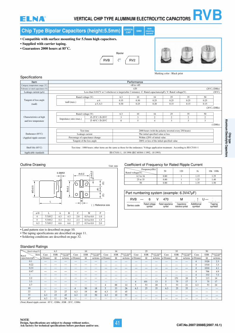
NOTEDesign, Specifications are subject to change without notice.Ask factory for technical specifications before purchase and/or use. CAT.No.2006/2007E(2006.10.1)
RVBVERTICAL CHIP TYPE ALUMINUM ELECTROLYTIC CAPACITORS
L
D0.
5
B0.
2
0.4
0.2
A 0.20.3MAX
W
(P)
(C)
(C)
( ): Reference size
Chip Type Bipolar Capacitors (height:5.5mm)
• Compatible with surface mounting for 5.5mm high capacitors.• Supplied with carrier taping.• Guarantees 2000 hours at 85˚C.
Marking color : Black print
RVB RV2
Bipolar
Specifications
Outline Drawing
Standard Ratings
Coefficient of Frequency for Rated Ripple Current
Item PerformanceCategory temperature range (˚C)
Tolerance at rated capacitance (%)
Leakage current (µA)
Tangent of loss angle
(tan )
Characteristics at high
and low temperature
Endurance (85˚C)
(Applied ripple current)
Shelf life (85˚ SIJotgnidroccA:tnemtaertnoitacilppaegatloV.ecnarudneehtrofesohtsaemasehterasmetirehto;sruoh0001:emittseT)C C5101-1
Applicable standards JIS C5101-1, -18 1998 (IEC 60384-1 1992, -18 1993)
40 to 85
20
Less than 0.01CV or 3 whichever is larger(after 2 minutes) C: Rated capacitance(µF); V: Rated voltage(V)
05535261013.6)V(egatlovdetaR
0.35 0.30 0.25 0.25 0.25 0.25
0.30 0.25 0.20 0.15 0.15 0.15tan (max.)
(20˚C)
(20˚C,120Hz)
(20˚C,120Hz)
(120Hz)
Test time
Leakage current
Percentage of capacitance change
Tangent of the loss angle
2000 hours (with the polarity inverted every 250 hours)
The initial specified value or less
Within 20% of initial value
200% or less of the initial specified value
05535261013.6)V(egatlovdetaR
3 3 2 2 2 2
8 5 4 3 3 3Impedance ratio (max.)
25˚C / 20˚C
40˚C / 20˚C
ø 4
ø 5, 6.3
Unit: mm
Rated voltage(V)
Frequency(Hz)
6.3 to 16
25 to 35
50
(Note) Rated ripple current : 85˚C, 120Hz ; ESR : 20˚C, 120Hz
50 120 1k 10k . 100k
0.80 1 1.15 1.25
0.80 1 1.25 1.40
0.80 1 1.35 1.50
0.1
0.22
0.33
0.47
1
2.2
3.3
4.7
10
22
33
47
Rated voltage(V) 05535261013.6
ItemRatedcapacitance(µF)
— — —
— — —
— — —
— — —
— — —
— — —
— — —
— — —
— — —
5 23 27
6.3 15 45
6.3 11 54
— — —
— — —
— — —
— — —
— — —
— — —
— — —
— — —
4 50 18
6.3 19 40
6.3 13 50— — —
— — —
— — —
— — —
— — —
— — —
— — —
— — —
4 88 14
5 33 26
6.3 15 45
6.3 10 55— — —
— — —
— — —
— — —
— — —
— — —
— — —
4 101 13
5 53 20
6.3 25 35
— — —
— — —— — —
— — —
— — —
— — —
— — —
— — —
4 151 10
5 75 17
5 53 21
6.3 25 35
— — —
— — —
— — —
4 3320 2.3
4 1510 3.3
4 1010 4.1
4 706 4.9
4 332 7.2
5 113 14
5 75 17
6.3 53 24
— — —
— — —
— — —
— — —
Case ESR
ø D(mm) mArms
Rated ripplecurrent Case ESR
ø D(mm) mArms
Rated ripplecurrent Case ESR
ø D(mm) mArms
Rated ripplecurrent Case ESR
ø D(mm) mArms
Rated ripplecurrent Case ESR
ø D(mm) mArms
Rated ripplecurrent Case ESR
ø D(mm) mArms
Rated ripplecurrent
4
5
6.3
ø D5.3 0.2
5.3 0.2
5.3 0.2
L
4.3
5.3
6.6
A
4.3
5.3
6.6
B
2.0
2.3
2.7
C
0.5 to 0.8
0.5 to 0.8
0.5 to 0.8
W
1.0
1.5
2.0
P
• Land pattern size is described on page 10.• The taping spesifications are described on page 11.• Soldering conditions are described on page 32.
Part numbering system (example: 6.3V47µF)
RVB — V
Series code
6 470 MRated voltage
symbolRated capacitance
symbolCapacitance
tolerance symbol
—Tapingsymbol
Additionalsymbol
U
GREENCAP SMD
Anti-cleaningsolvent
®
Chip typeAlum
inum Electrolytic Capacitors
NOTEDesign, Specifications are subject to change without notice.Ask factory for technical specifications before purchase and/or use. 41 CAT.No.2007/2008E(2007.10.1)
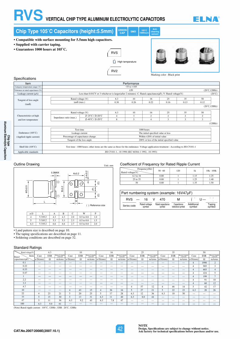
NOTEDesign, Specifications are subject to change without notice.Ask factory for technical specifications before purchase and/or use.CAT.No.2006/2007E(2006.10.1)
RVS VERTICAL CHIP TYPE ALUMINUM ELECTROLYTIC CAPACITORS
Chip Type 105˚C Capacitors (height:5.5mm)
• Compatible with surface mounting for 5.5mm high capacitors.• Supplied with carrier taping.• Guarantees 1000 hours at 105˚C.
Marking color : Black print
RVS
RV2
High temperature
L
D0.
5
B0.
2
(P)
(C)
(C)
0.4
0.2
A 0.2
( ): Reference size
0.3MAX
W
Specifications
Outline Drawing
Standard Ratings
Coefficient of Frequency for Rated Ripple Current
Item PerformanceCategory temperature range (˚C)
Tolerance at rated capacitance (%)
Leakage current (µA)
Tangent of loss angle
(tan )
Characteristics at high
and low temperature
Endurance (105˚C)
(Applied ripple current)
Shelf life (105˚ SIJotgnidroccA:tnemtaertnoitacilppaegatloV.ecnarudneehtrofesohtsaemasehterasmetirehto;sruoh0001:emittseT)C C5101-1
Applicable standards JIS C5101-1, -18 1998 (IEC 60384-1 1992, -18 1993)
55 to 105
20
Less than 0.01CV or 3 whichever is larger(after 2 minutes) C: Rated capacitance(µF); V: Rated voltage(V)
05535261013.6)V(egatlovdetaR
0.30 0.26 0.22 0.16 0.13 0.12tan (max.)
(20˚C)
(20˚C,120Hz)
(20˚C,120Hz)
(120Hz)
Test time
Leakage current
Percentage of capacitance change
Tangent of the loss angle
1000 hours
The initial specified value or less
Within 20% of initial value
200% or less of the initial specified value
05535261013.6)V(egatlovdetaR
4 3 2 2 2 2
8 5 4 3 3 3Impedance ratio (max.)
25˚C / 20˚C
40˚C / 20˚C
Unit: mm
Rated voltage(V)
Frequency(Hz)
6.3 to 16
25 to 35
50
(Note) Rated ripple current : 105˚C, 120Hz ; ESR : 20˚C, 120Hz
50 . 60 120 1k 10k . 100k
0.80 1 1.15 1.25
0.80 1 1.25 1.40
0.80 1 1.35 1.50
0.1
0.22
0.33
0.47
1
2.2
3.3
4.7
10
22
33
47
100
Rated voltage(V) 05535261013.6
ItemRatedcapacitance(µF)
— — —
— — —
— — —
— — —
— — —
— — —
— — —
— — —
— — —
4 23 21
5 15 30
5 11 36
6.3 5.0 61
— — —
— — —
— — —
— — —
— — —
— — —
— — —
— — —
4 43 15
5 20 25
5 13 31
6.3 9.2 43— — —
— — —
— — —
— — —
— — —
— — —
— — —
— — —
— — —
4 36 16
5 17 28
6.3 11 40
6.3 7.8 47— — —
— — —
— — —
— — —
— — —
— — —
— — —
— — —
4 57 12
5 27 21
6.3 12 36
6.3 8.0 44
— — —— — —
— — —
— — —
— — —
— — —
— — —
— — —
— — —
4 46 14
5 22 23
6.3 10 50
— — —
— — —
— — —
4 1990 2
4 905 3
4 603 4
4 424 5
4 199 7
4 91 10
4 60 12
5 42 17
6.3 20 26
— — —
— — —
— — —
— — —
Case ESR
ø D(mm) mArms
Rated ripplecurrent Case ESR
ø D(mm) mArms
Rated ripplecurrent Case ESR
ø D(mm) mArms
Rated ripplecurrent Case ESR
ø D(mm) mArms
Rated ripplecurrent Case ESR
ø D(mm) mArms
Rated ripplecurrent Case ESR
ø D(mm) mArms
Rated ripplecurrent
4
5
6.3
ø D5.3 0.2
5.3 0.2
5.3 0.2
L
4.3
5.3
6.6
A
4.3
5.3
6.6
B
2.0
2.3
2.7
C
0.5 to 0.8
0.5 to 0.8
0.5 to 0.8
W
1.0
1.5
2.0
P
• Land pattern size is described on page 10.• The taping spesifications are described on page 11.• Soldering conditions are described on page 32.
Part numbering system (example: 16V47µF)
RVS — V
Series code
16 470 MRated voltage
symbolRated capacitance
symbolCapacitance
tolerance symbol
—Tapingsymbol
Additionalsymbol
U
105˚C1000hours
GREENCAP SMD
Anti-cleaningsolvent
®
Chip typeAlum
inum Electrolytic Capacitors
NOTEDesign, Specifications are subject to change without notice.Ask factory for technical specifications before purchase and/or use.42CAT.No.2007/2008E(2007.10.1)
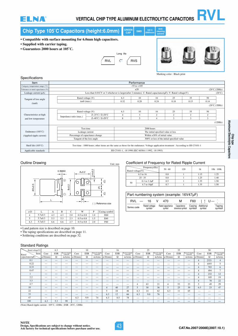
NOTEDesign, Specifications are subject to change without notice.Ask factory for technical specifications before purchase and/or use. CAT.No.2006/2007E(2006.10.1)
RVLVERTICAL CHIP TYPE ALUMINUM ELECTROLYTIC CAPACITORS
Ratedcapacitance(µF)
Chip Type 105˚C Capacitors (height:6.0mm)
• Compatible with surface mounting for 6.0mm high capacitors.• Supplied with carrier taping.• Guarantees 2000 hours at 105˚C.
Marking color : Black print
RVL RVS
Long life
L
D0.
5
B0.
2
(P)
(C)
(C)
0.4
0.2
A 0.2
( ): Reference size
0.3MAX
W
Specifications
Outline Drawing
Standard Ratings
Coefficient of Frequency for Rated Ripple Current
Item PerformanceCategory temperature range (˚C)
Tolerance at rated capacitance (%)
Leakage current (µA)
Tangent of loss angle
(tan )
Characteristics at high
and low temperature
Endurance (105˚C)
(Applied ripple current)
Shelf life (105˚ SIJotgnidroccA:tnemtaertnoitacilppaegatloV.ecnarudneehtrofesohtsaemasehterasmetirehto;sruoh0001:emittseT)C C5101-1
Applicable standards JIS C5101-1, -18 1998 (IEC 60384-1 1992, -18 1993)
55 to 105
20
Less than 0.01CV or 3 whichever is larger(after 2 minutes) C: Rated capacitance(µF); V: Rated voltage(V)
05535261013.6)V(egatlovdetaR
0.32 0.28 0.24 0.18 0.15 0.14tan (max.)
(20˚C)
(20˚C,120Hz)
(20˚C,120Hz)
(120Hz)
Test time
Leakage current
Percentage of capacitance change
Tangent of the loss angle
2000 hours
The initial specified value or less
Within 30% of initial value
300% or less of the initial specified value
05535261013.6)V(egatlovdetaR
4 3 2 2 2 2
8 5 4 3 3 3Impedance ratio (max.)
25˚C / 20˚C
40˚C / 20˚C
Unit: mm
Rated voltage(V)
Frequency(Hz)
6.3 to 16
25 . 35
0.1 to 3.3µF
4.7 to 10µF50
(Note) Rated ripple current : 105˚C, 120Hz ; ESR : 20˚C, 120Hz
50 . 60 120 1k 10k . 100k
0.8 1 1.15 1.25
0.8 1 1.25 1.40
0.5 1 1.35 1.50
0.7 1 1.35 1.50
0.1
0.22
0.33
0.47
1
2.2
3.3
4.7
10
22
33
47
100
Rated voltage(V) 05535261013.6
Item
— — —
— — —
— — —
— — —
— — —
— — —
— — —
— — —
— — —
— — —
— — —
— — —
6.3 5.3 99
— — —
— — —
— — —
— — —
— — —
— — —
— — —
— — —
— — —
— — —
— — —
6.3 9.9 74— — —
— — —
— — —
— — —
— — —
— — —
— — —
— — —
— — —
4 40 27
5 18 46
6.3 12 66
6.3 8.5 78— — —
— — —
— — —
— — —
— — —
— — —
— — —
— — —
4 63 21
5 30 36
6.3 14 62
6.3 9.0 76
— — —— — —
— — —
— — —
— — —
— — —
— — —
— — —
— — —
4 53 23
5 25 39
6.3 11 65
— — —
— — —
— — —
4 2321 4
4 1055 5
4 703 6
4 494 7
4 232 12
4 105 19
4 70 22
5 49 29
6.3 23 47
— — —
— — —
— — —
— — —
Case ESR
ø D(mm) mArms
Rated ripplecurrent Case ESR
ø D(mm) mArms
Rated ripplecurrent Case ESR
ø D(mm) mArms
Rated ripplecurrent Case ESR
ø D(mm) mArms
Rated ripplecurrent Case ESR
ø D(mm) mArms
Rated ripplecurrent Case ESR
ø D(mm) mArms
Rated ripplecurrent
4
5
6.3
ø D5.7 0.3
5.7 0.3
5.7 0.3
L
4.3
5.3
6.6
A
4.3
5.3
6.6
B
2.0
2.3
2.7
C
0.5 to 0.8
0.5 to 0.8
0.5 to 0.8
W
1.0
1.5
2.0
D60
E60
F60
P Casing symbol
• Land pattern size is described on page 10.• The taping spesifications are described on page 11.• Soldering conditions are described on page 32.
Part numbering system (example: 16V47µF)
RVL — V
Series code
16 470 MRated voltage
symbolRated capacitance
symbolCapacitance
tolerance symbol
F60Casingsymbol
—Tapingsymbol
Additionalsymbol
U
105˚C2000hours
GREENCAP SMD
Anti-cleaningsolvent
®
Chip typeAlum
inum Electrolytic Capacitors
NOTEDesign, Specifications are subject to change without notice.Ask factory for technical specifications before purchase and/or use. 43 CAT.No.2007/2008E(2007.10.1)
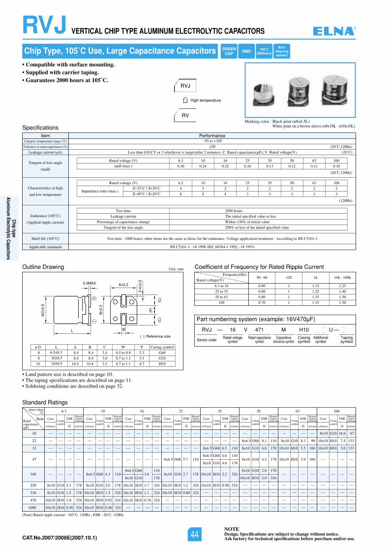
NOTEDesign, Specifications are subject to change without notice.Ask factory for technical specifications before purchase and/or use.CAT.No.2006/2007E(2006.10.1)
RVJ VERTICAL CHIP TYPE ALUMINUM ELECTROLYTIC CAPACITORS
Chip Type, 105˚C Use, Large Capacitance Capacitors
• Compatible with surface mounting.• Supplied with carrier taping.• Guarantees 2000 hours at 105˚C.
Marking color : Black print (ø8x6.5L)White print on a brown sleeve (ø8x10L . ø10x10L)
RVJ
RV
High temperature
L
D0.
5
B0.
2
(P)
(C)
(C)
0.4
0.2
A 0.2
( ): Reference size
0.3MAX
W
tnerruCelppiRdetaRrofycneuqerFfotneiciffeoCgniwarDeniltuO Unit: mm
Rated voltage(V)
Frequency(Hz)
6.3 to 16
25 to 35
50 to 63
100
50 . 60 120 1k 10k . 100k
0.80 1 1.15 1.25
0.80 1 1.25 1.40
0.80 1 1.35 1.50
0.70 1 1.35 1.50
8
8
10
ø D6.5 0.3
10 0.5
10 0.5
L
8.4
8.4
10.4
A
8.4
8.4
10.4
B
3.4
3.0
3.3
C
0.5 to 0.8
0.7 to 1.1
0.7 to 1.1
W
2.3
3.1
4.7
G68
G10
H10
P Casing symbol
SpecificationsItem Performance
Category temperature range (˚C)
Tolerance at rated capacitance (%)
Leakage current (µA)
Tangent of loss angle
(tan )
Characteristics at high
and low temperature
Endurance (105˚C)
(Applied ripple current)
Shelf life (105˚ SIJotgnidroccA:tnemtaertnoitacilppaegatloV.ecnarudneehtrofesohtsaemasehterasmetirehto;sruoh0001:emittseT)C C5101-1
Applicable standards JIS C5101-1, -18 1998 (IEC 60384-1 1992, -18 1993)
55 to 105
20
Less than 0.01CV or 3 whichever is larger(after 2 minutes) C: Rated capacitance(µF); V: Rated voltage(V)
0013605535261013.6)V(egatlovdetaR
0.30 0.24 0.22 0.16 0.13 0.12 0.11 0.10tan (max.)
(20˚C)
(20˚C,120Hz)
(20˚C,120Hz)
(120Hz)
Test time
Leakage current
Percentage of capacitance change
Tangent of the loss angle
2000 hours
The initial specified value or less
Within 20% of initial value
200% or less of the initial specified value
0013605535261013.6)V(egatlovdetaR
4 3 2 2 2 2 2 2
8 5 4 3 3 3 3 3Impedance ratio (max.)
25˚C / 20˚C
40˚C / 20˚C
Standard Ratings
(Note) Rated ripple current : 105˚C, 120Hz ; ESR : 20˚C, 120Hz
10
22
33
47
100
220
330
470
1000
Rated voltage(V) 6.3
ItemRatedcapacitance(µF)
— — — —
— — — —
— — — —
— — — —
— — — —
8x10 G10 2.3 178
8x10 G10 1.5 178
10x10 H10 1.0 324
10x10 H10 0.50 324
Case
ø D(mm)
Casingsymbol
ESR
mArms
Ratedripplecurrent
10
— — — —
— — — —
— — — —
— — — —
8x6.5 G68 4.3 110
8x10 G10 2.0 178
10x10 H10 1.3 324
10x10 H10 0.92 324
10x10 H10 0.40 324
Case
ø D(mm)
Casingsymbol
ESR
mArms
Ratedripplecurrent
16
— — — —
— — — —
— — — —
— — — —
8x6.5 G683.6
110
8x10 G10 178
10x10 H10 1.7 324
10x10 H10 1.1 324
10x10 H10 0.78 324
— — — —
Case
ø D(mm)
Casingsymbol
ESR
mArms
Ratedripplecurrent
25
— — — —
— — — —
— — — —
8x6.5 G68 5.7 110
8x10 G10 2.7 178
10x10 H10 1.2 324
10x10 H10 0.80 324
— — — —
— — — —
Case
ø D(mm)
Casingsymbol
ESR
mArms
Ratedripplecurrent
35
— — — —
— — — —
8x6.5 G68 6.5 110
8x6.5 G68 4.6 110
8x10 G10 4.6 178
10x10 H10 2.2 324
10x10 H10 0.98 324
— — — —
— — — —
— — — —
Case
ø D(mm)
Casingsymbol
ESR
mArms
Ratedripplecurrent
50
— — — —
8x6.5 G68 9.1 110
8x10 G10 6.0 178
8x10 G10 4.2 178
8x10 G10 2.0 178
10x10 H10 2.0 324
— — — —
— — — —
— — — —
— — — —
Case
ø D(mm)
Casingsymbol
ESR
mArms
Ratedripplecurrent
63
— — — —
8x10 G10 8.3 99
10x10 H10 5.5 160
10x10 H10 3.9 160
— — — —
— — — —
— — — —
— — — —
— — — —
Case
ø D(mm)
Casingsymbol
ESR
mArms
Ratedripplecurrent
100
8x10 G10 16.6 67
10x10 H10 7.5 133
10x10 H10 5.0 133
— — — —
— — — —
— — — —
— — — —
— — — —
— — — —
Case
ø D(mm)
Casingsymbol
ESR
mArms
Ratedripplecurrent
• Land pattern size is described on page 10.• The taping spesifications are described on page 11.• Soldering conditions are described on page 32.
Part numbering system (example: 16V470µF)
RVJ — V
Series code
16 471 MRated voltage
symbolRated capacitance
symbolCapacitance
tolerance symbol
H10Casingsymbol
—Tapingsymbol
Additionalsymbol
U
105˚C2000hours
GREENCAP SMD
Anti-cleaningsolvent
®
Chip typeAlum
inum Electrolytic Capacitors
NOTEDesign, Specifications are subject to change without notice.Ask factory for technical specifications before purchase and/or use.44CAT.No.2007/2008E(2007.10.1)
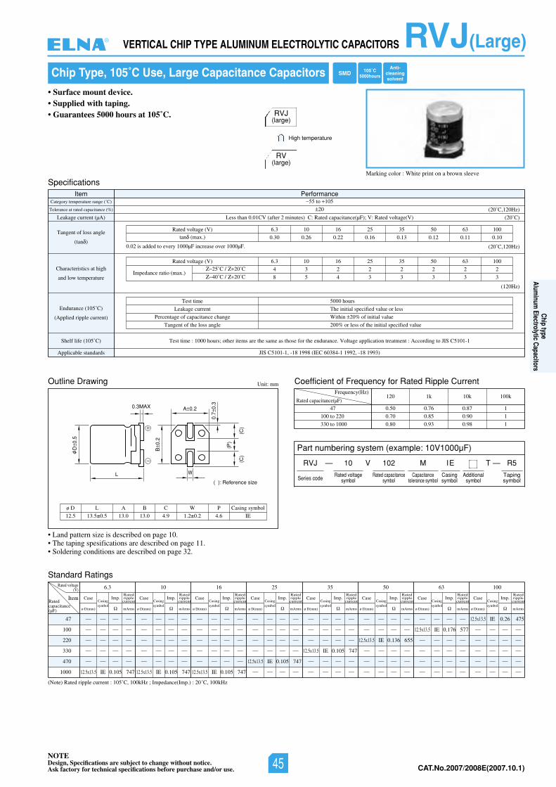
NOTEDesign, Specifications are subject to change without notice.Ask factory for technical specifications before purchase and/or use. CAT.No.2006/2007E(2006.10.1)
RVJ(Large)VERTICAL CHIP TYPE ALUMINUM ELECTROLYTIC CAPACITORS
• Land pattern size is described on page 10.• The taping spesifications are described on page 11.• Soldering conditions are described on page 32.
Chip Type, 105˚C Use, Large Capacitance Capacitors
• Surface mount device.• Supplied with taping.• Guarantees 5000 hours at 105˚C.
Marking color : White print on a brown sleeve
Specifications
Outline Drawing
Item PerformanceCategory temperature range (˚C)
Tolerance at rated capacitance (%)
Leakage current (µA)
Tangent of loss angle
(tan )
Characteristics at high
and low temperature
Endurance (105˚C)
(Applied ripple current)
Shelf life (105˚ SIJotgnidroccA:tnemtaertnoitacilppaegatloV.ecnarudneehtrofesohtsaemasehterasmetirehto;sruoh0001:emittseT)C C5101-1
Applicable standards JIS C5101-1, -18 1998 (IEC 60384-1 1992, -18 1993)
55 to 105
20
02()V(egatlovdetaR:V;)Fµ(ecnaticapacdetaR:C)setunim2retfa(VC10.0nahtsseL ˚C)
(20˚C,120Hz)
Test time
Leakage current
Percentage of capacitance change
Tangent of the loss angle
5000 hours
The initial specified value or less
Within 20% of initial value
200% or less of the initial specified value
Unit: mm
Part numbering system (example: 10V1000µF)
— V TRVJ
Series code
10
Rated voltagesymbol
102
Rated capacitancesymbol
M
Capacitancetolerance symbol
IE
Casingsymbol
— R5
Tapingsymbol
RVJ(large)
RV(large)
High temperature
0013605535261013.6)V(egatlovdetaR
0.30 0.26 0.22 0.16 0.13 0.12 0.11 0.10tan (max.)
(20˚C,120Hz)
(120Hz)
0013605535261013.6)V(egatlovdetaR
4 3 2 2 2 2 2 2
8 5 4 3 3 3 3 3Impedance ratio (max.)
25˚C / 20˚C
40˚C / 20˚C
0.02 is added to every 1000µF increase over 1000µF.
Standard Ratings
(Note) Rated ripple current : 105˚C, 100kHz ; Impedance(Imp.) : 20˚C, 100kHz
47
100
220
330
470
1000
Rated voltage(V) 6.3
ItemRatedcapacitance(µF)
— — — —
— — — —
— — — —
— — — —
— — — —
12.5x13.5 IE 0.105 747
— — — —
— — — —
— — — —
— — — —
— — — —
12.5x13.5 IE 0.105 747
— — — —
— — — —
— — — —
— — — —
— — — —
12.5x13.5 IE 0.105 747
— — — —
— — — —
— — — —
— — — —
12.5x13.5 IE 0.105 747
— — — —
— — — —
— — — —
— — — —
12.5x13.5 IE 0.105 747
— — — —
— — — —
— — — —
12.5x13.5 IE 0.136 655
— — — —— — — —
— — — —
— — — —
12.5x13.5 IE 0.176 577
— — — —
— — — —— — — —
— — — —
— — — —
12.5x13.5 IE 0.26 475
— — — —
— — — —
— — — —
— — — —
— — — —
Case
ø D(mm)
Casingsymbol
Imp.
mArms
Ratedripplecurrent
10
Case
ø D(mm)
Casingsymbol
Imp.
mArms
Ratedripplecurrent
16
Case
ø D(mm)
Casingsymbol
Imp.
mArms
Ratedripplecurrent
25
Case
ø D(mm)
Casingsymbol
Imp.
mArms
Ratedripplecurrent
35
Case
ø D(mm)
Casingsymbol
Imp.
mArms
Ratedripplecurrent
50
Case
ø D(mm)
Casingsymbol
Imp.
mArms
Ratedripplecurrent
63
Case
ø D(mm)
Casingsymbol
Imp.
mArms
Ratedripplecurrent
100
Case
ø D(mm)
Casingsymbol
Imp.
mArms
Ratedripplecurrent
Coefficient of Frequency for Rated Ripple Current
Rated capacitance(µF)
Frequency(Hz)
47
100 to 220
330 to 1000
120 1k 10k 100k
0.50 0.76 0.87 1
0.70 0.85 0.90 1
0.80 0.93 0.98 1
L
D0.
5
B0.
2
(P)
(C)
(C)
0.7
0.3
A 0.20.3MAX
W
( ): Reference size
12.5
ø D
13.5±0.5
L
13.0 13.0
A B
4.9
C
1.2±0.2
W
4.6 IE
P Casing symbol
105˚C5000hoursSMD
Anti-cleaningsolvent
Additionalsymbol
®
Chip typeAlum
inum Electrolytic Capacitors
NOTEDesign, Specifications are subject to change without notice.Ask factory for technical specifications before purchase and/or use. 45 CAT.No.2007/2008E(2007.10.1)
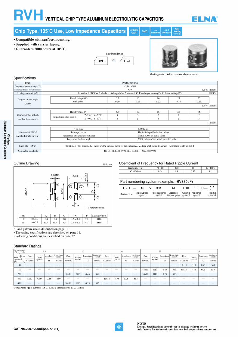
NOTEDesign, Specifications are subject to change without notice.Ask factory for technical specifications before purchase and/or use.CAT.No.2006/2007E(2006.10.1)
RVH VERTICAL CHIP TYPE ALUMINUM ELECTROLYTIC CAPACITORS
(Note) Rated ripple current : 105˚C, 100kHz ; Impedance : 20˚C, 100kHz
47
100
220
330
470
Rated voltage(V) 6.3
ItemRatedcapacitance(µF)
— — — —
— — — —
— — — —
8x10 G10 0.45 369
— — — —
— — — —
— — — —
8x10 G10 0.45 369
— — — —
10x10 H10 0.25 553
— — — —
— — — —
— — — —
10x10 H10 0.25 553
— — — —
— — — —
8x10 G10 0.45 369
10x10 H10 0.25 553
— — — —
— — — —
8x10 G10 0.45 369
10x10 H10 0.25 553
— — — —
— — — —
— — — —
Case
ø D(mm)
Casingsymbol
Impedance
mArms
Rated ripplecurrent
10
Case
ø D(mm)
Casingsymbol
Impedance
mArms
Rated ripplecurrent
16
Case
ø D(mm)
Casingsymbol
Impedance
mArms
Rated ripplecurrent
25
Case
ø D(mm)
Casingsymbol
Impedance
mArms
Rated ripplecurrent
35
Case
ø D(mm)
Casingsymbol
Impedance
mArms
Rated ripplecurrent
Chip Type, 105˚C Use, Low Impedance Capacitors
• Compatible with surface mounting.• Supplied with carrier taping.• Guarantees 2000 hours at 105˚C.
Marking color : White print on a brown sleeve
RVH RVJ
Low impedance
L
D0.
5
B0.
2
(P)
(C)
(C)
0.4
0.2
A 0.2
( ): Reference size
0.3MAX
W
Specifications
Outline Drawing
Standard Ratings
Coefficient of Frequency for Rated Ripple Current
Item PerformanceCategory temperature range (˚C)
Tolerance at rated capacitance (%)
Leakage current (µA)
Tangent of loss angle
(tan )
Characteristics at high
and low temperature
Endurance (105˚C)
(Applied ripple current)
Shelf life (105˚ SIJotgnidroccA:tnemtaertnoitacilppaegatloV.ecnarudneehtrofesohtsaemasehterasmetirehto;sruoh0001:emittseT)C C5101-1
Applicable standards JIS C5101-1, -18 1998 (IEC 60384-1 1992, -18 1993)
55 to 105
20
Less than 0.01CV or 3 whichever is larger(after 2 minutes) C: Rated capacitance(µF); V: Rated voltage(V)
535261013.6)V(egatlovdetaR
0.30 0.26 0.22 0.16 0.13tan (max.)
(20˚C)
(20˚C,120Hz)
(20˚C,120Hz)
(120Hz)
Test time
Leakage current
Percentage of capacitance change
Tangent of the loss angle
2000 hours
The initial specified value or less
Within 20% of initial value
200% or less of the initial specified value
535261013.6)V(egatlovdetaR
4 3 2 2 2
8 5 4 3 3Impedance ratio (max.)
25˚C / 20˚C
40˚C / 20˚C
Unit: mm
Frequency (Hz)
Coefficient
50 . 60 120 1k 10k . 100k
0.64 0.8 0.93 1
8
10
ø D10 0.5
10 0.5
L
8.4
10.4
8.4
10.4
A B
3.0
3.3
C
0.7 to 1.1
0.7 to 1.1
W
3.1
4.7
G10
H10
P Casing symbol
• Land pattern size is described on page 10.• The taping spesifications are described on page 11.• Soldering conditions are described on page 32.
Part numbering system (example: 16V330µF)
RVH — V
Series code
16 331 MRated voltage
symbolRated capacitance
symbolCapacitance
tolerance symbol
H10Casingsymbol
—Tapingsymbol
Additionalsymbol
U
105˚C2000hours
LowImpedance
GREENCAP SMD
Anti-cleaningsolvent
®
Chip typeAlum
inum Electrolytic Capacitors
NOTEDesign, Specifications are subject to change without notice.Ask factory for technical specifications before purchase and/or use.46CAT.No.2007/2008E(2007.10.1)
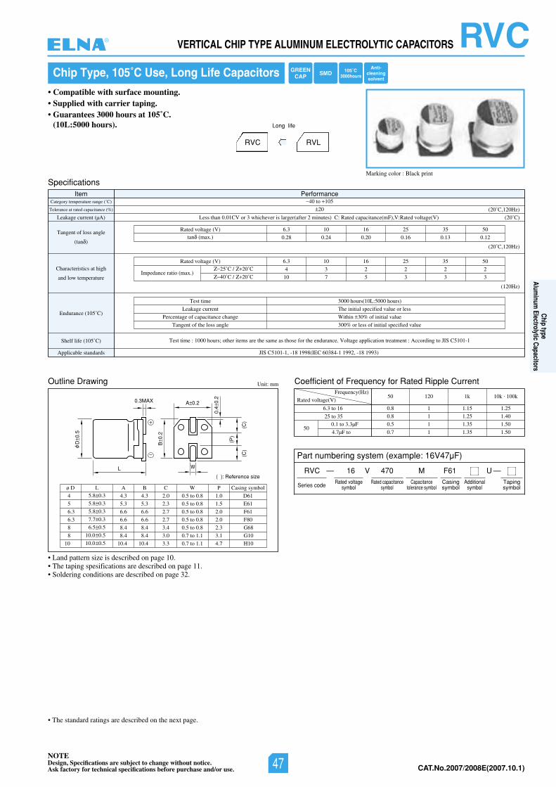
NOTEDesign, Specifications are subject to change without notice.Ask factory for technical specifications before purchase and/or use. CAT.No.2006/2007E(2006.10.1)
RVCVERTICAL CHIP TYPE ALUMINUM ELECTROLYTIC CAPACITORS
Chip Type, 105˚C Use, Long Life Capacitors
• Compatible with surface mounting.• Supplied with carrier taping.• Guarantees 3000 hours at 105˚C.
(10L:5000 hours).
Marking color : Black print
RVC RVL
Long life
L
D0.
5
B0.
2
(P)
(C)
(C)
0.4
0.2
A 0.2
( ): Reference size
0.3MAX
W
Specifications
Outline Drawing Coefficient of Frequency for Rated Ripple Current
Item PerformanceCategory temperature range (˚C)
Tolerance at rated capacitance (%)
Leakage current (µA)
Tangent of loss angle
(tan )
Characteristics at high
and low temperature
Endurance (105˚C)
Shelf life (105˚ Test time : 1000 hours; other items are the same as those for the endurance. Voltage application treatment : According to JIS C5101-1)C
Applicable standards JIS C5101-1, -18 1998(IEC 60384-1 1992, -18 1993)
40 to 105
20
Less than 0.01CV or 3 whichever is larger(after 2 minutes) C: Rated capacitance(mF),V:Rated voltage(V)
05535261013.6)V(egatlovdetaR
0.28 0.24 0.20 0.16 0.13 0.12tan (max.)
(20˚C)
(20˚C,120Hz)
(20˚C,120Hz)
(120Hz)
Test time
Leakage current
Percentage of capacitance change
Tangent of the loss angle
3000 hours(10L:5000 hours)
The initial specified value or less
Within 30% of initial value
300% or less of initial specified value
05535261013.6)V(egatlovdetaR
4 3 2 2 2 2
10 7 5 3 3 3Impedance ratio (max.)
25˚C / 20˚C
40˚C / 20˚C
Unit: mm
Rated voltage(V)
Frequency(Hz)
6.3 to 16
25 to 350.1 to 3.3µF
4.7µF to 50
50 120 1k 10k . 100k
0.8 1 1.15 1.25
0.8 1 1.25 1.40
0.5 1 1.35 1.50
0.7 1 1.35 1.50
4
5
6.3
ø D5.8 0.3
5.8 0.3
5.8 0.3
L
4.3
5.3
6.6
A
4.3
5.3
6.6
B
2.0
2.3
2.7
C
0.5 to 0.8
0.5 to 0.8
0.5 to 0.8
W
1.0
1.5
2.0
D61
E61
F61
6.3 7.7 0.3 6.6 6.6 2.7 0.5 to 0.8 2.0 F80
8 6.5 0.5 8.4 8.4 3.4 0.5 to 0.8 2.3 G68
8 10.0 0.5 8.4 8.4 3.0 0.7 to 1.1 3.1 G10
10 10.0 0.5 10.4 10.4 3.3 0.7 to 1.1 4.7 H10
P Casing symbol
• Land pattern size is described on page 10.• The taping spesifications are described on page 11.• Soldering conditions are described on page 32.
3000hoursGREEN
CAP SMDAnti-
cleaningsolvent
105˚C
Part numbering system (example: 16V47µF)
RVC — V
Series code
16 470 MRated voltage
symbolRated capacitance
symbolCapacitance
tolerance symbol
F61Casingsymbol
—Tapingsymbol
Additionalsymbol
U
• The standard ratings are described on the next page.
®
Chip typeAlum
inum Electrolytic Capacitors
NOTEDesign, Specifications are subject to change without notice.Ask factory for technical specifications before purchase and/or use. 47 CAT.No.2007/2008E(2007.10.1)
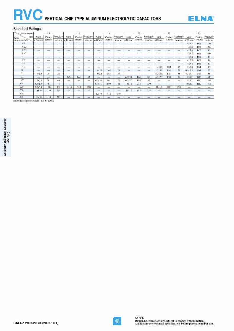
NOTEDesign, Specifications are subject to change without notice.Ask factory for technical specifications before purchase and/or use.CAT.No.2006/2007E(2006.10.1)
RVC VERTICAL CHIP TYPE ALUMINUM ELECTROLYTIC CAPACITORS
Standard Ratings
Ratedcapacitance(µF)
(Note) Rated ripple current : 105˚C, 120Hz
0.1
0.22
0.33
0.47
1
2.2
3.3
4.7
10
22
33
47
100
220
330
470
1000
Rated voltage(V) 05535261013.6
Item Case Casingsymbol
Casingsymbolø D(mm) mArms
Rated ripplecurrent Case Casing
symbolCase Casing
symbolCase Casing
symbolCase Casing
symbolCase
ø D(mm) mArms
Rated ripplecurrent
ø D(mm) mArms
Rated ripplecurrent
ø D(mm) mArms
Rated ripplecurrent
ø D(mm) mArms
Rated ripplecurrent
ø D(mm) mArms
Rated ripplecurrent
— — —
— — —
— — —
— — —
— — —
— — —
— — —
— — —
— — —
4x5.8 D61 26
— — —
5x5.8 E61 46
6.3x5.8 F61 71
6.3x7.7 F80 101
8x10 G10 230
— — —
10x10 H10 313
— — —
— — —
— — —
— — —
— — —
— — —
— — —
— — —
— — —
— — —
5x5.8 E61 43
— — —
— — —
8x10 G10 160
— — —
— — —
— — —
— — —
— — —
— — —
— — —
— — —
— — —
— — —
— — —
4x5.8 D61 28
5x5.8 E61 39
— — —
6.3x5.8 F61 70
6.3x7.7 F80 81
— — —
— — —
10x10 H10 340
— — —
— — —
— — —
— — —
— — —
— — —
— — —
— — —
— — —
— — —
— — —
6.3x5.8 F61 60
6.3x7.7 F80 65
8x10 G10 130
— — —
10x10 H10 238
— — —
— — —
— — —
— — —
— — —
— — —
— — —
— — —
— — —
4x5.8 D61 16
5x5.8 E61 28
6.3x5.8 F61 55
6.3x7.7 F80 57
— — —
— — —
10x10 H10 220
— — —
— — —
— — —
4x5.8 D61 1.0
4x5.8 D61 2.6
4x5.8 D61 3.2
4x5.8 D61 5.0
4x5.8 D61 10
4x5.8 D61 16
4x5.8 D61 17
5x5.8 E61 23
6.3x5.8 F61 35
6.3x7.7 F80 58
8x10 G10 91
8x10 G10 100
10x10 H10 160
— — —
— — —
— — —
— — —
®
Chip typeAlum
inum Electrolytic Capacitors
NOTEDesign, Specifications are subject to change without notice.Ask factory for technical specifications before purchase and/or use.48CAT.No.2007/2008E(2007.10.1)
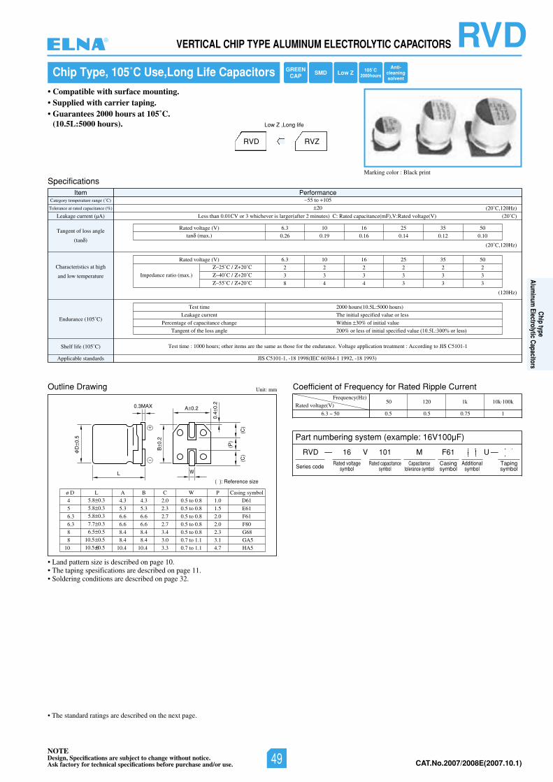
NOTEDesign, Specifications are subject to change without notice.Ask factory for technical specifications before purchase and/or use. CAT.No.2006/2007E(2006.10.1)
RVDVERTICAL CHIP TYPE ALUMINUM ELECTROLYTIC CAPACITORS
Chip Type, 105˚C Use,Long Life Capacitors
• Compatible with surface mounting.• Supplied with carrier taping.• Guarantees 2000 hours at 105˚C.
(10.5L:5000 hours).
Marking color : Black print
RVD RVZ
Low Z ,Long life
L
D0.
5
B0.
2
(P)
(C)
(C)
0.4
0.2
A 0.2
( ): Reference size
0.3MAX
W
Specifications
Outline Drawing Coefficient of Frequency for Rated Ripple Current
Item PerformanceCategory temperature range (˚C)
Tolerance at rated capacitance (%)
Leakage current (µA)
Tangent of loss angle
(tan )
Characteristics at high
and low temperature
Endurance (105˚C)
Shelf life (105˚ Test time : 1000 hours; other items are the same as those for the endurance. Voltage application treatment : According to JIS C5101-1)C
Applicable standards JIS C5101-1, -18 1998(IEC 60384-1 1992, -18 1993)
55 to 105
20
Less than 0.01CV or 3 whichever is larger(after 2 minutes) C: Rated capacitance(mF),V:Rated voltage(V)
05535261013.6)V(egatlovdetaR
0.26 0.19 0.16 0.14 0.12 0.10tan (max.)
(20˚C)
(20˚C,120Hz)
(20˚C,120Hz)
(120Hz)
Test time
Leakage current
Percentage of capacitance change
Tangent of the loss angle
2000 hours(10.5L:5000 hours)
The initial specified value or less
Within 30% of initial value
200% or less of initial specified value (10.5L:300% or less)
05535261013.6)V(egatlovdetaR
2 2 2 2 2 2
3 3 3 3 3 3
8 4 4 3 3 3
Impedance ratio (max.)
25˚C / 20˚C
40˚C / 20˚C
55˚C / 20˚C
Unit: mm
Rated voltage(V)
Frequency(Hz)
6.3 ~ 50
50 120 1k 10k.100k
0.5 0.5 0.75 1
4
5
6.3
ø D5.8 0.3
5.8 0.3
5.8 0.3
L
4.3
5.3
6.6
A
4.3
5.3
6.6
B
2.0
2.3
2.7
C
0.5 to 0.8
0.5 to 0.8
0.5 to 0.8
W
1.0
1.5
2.0
D61
E61
F61
6.3 7.7 0.3 6.6 6.6 2.7 0.5 to 0.8 2.0 F80
8 6.5 0.5 8.4 8.4 3.4 0.5 to 0.8 2.3 G68
8 10.5 0.5 8.4 8.4 3.0 0.7 to 1.1 3.1 GA5
10 10.5.00.5 10.4 10.4 3.3 0.7 to 1.1 4.7 HA5
P Casing symbol
• Land pattern size is described on page 10.• The taping spesifications are described on page 11.• Soldering conditions are described on page 32.
2000hoursGREEN
CAP SMD Low ZAnti-
cleaningsolvent
105˚C
Part numbering system (example: 16V100µF)
RVD — V
Series code
16 101 MRated voltage
symbolRated capacitance
symbolCapacitance
tolerance symbol
F61Casingsymbol
—Tapingsymbol
Additionalsymbol
U
• The standard ratings are described on the next page.
®
Chip typeAlum
inum Electrolytic Capacitors
NOTEDesign, Specifications are subject to change without notice.Ask factory for technical specifications before purchase and/or use. 49 CAT.No.2007/2008E(2007.10.1)
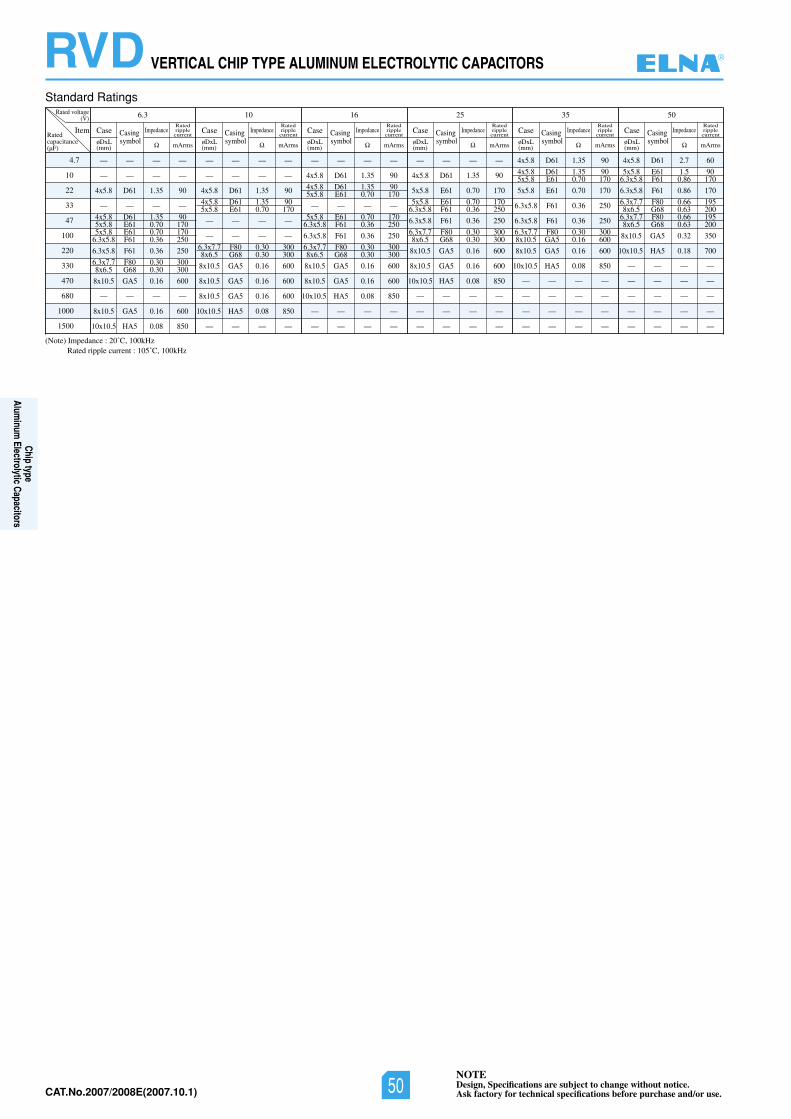
NOTEDesign, Specifications are subject to change without notice.Ask factory for technical specifications before purchase and/or use.CAT.No.2006/2007E(2006.10.1)
RVD VERTICAL CHIP TYPE ALUMINUM ELECTROLYTIC CAPACITORS
Standard Ratings
(Note) Impedance : 20˚C, 100kHz
10
4.7
22
33
47
100
220
330
470
680
1000
1500
Rated voltage(V) 6.3 10 16 25 35 50
ItemRatedcapacitance(µF)
Impedance
øDxL(mm) mArms
Ratedripplecurrent
Impedance
mArms
Ratedripplecurrent
Impedance
mArms
Ratedripplecurrent
Impedance
mArms
Ratedripplecurrent
Impedance
mArms
Ratedripplecurrent
Impedance
mArms
Ratedripplecurrent
Case Casingsymbol øDxL
(mm)
Case Casingsymbol øDxL
(mm)
Case Casingsymbol øDxL
(mm)
Case Casingsymbol øDxL
(mm)
Case Casingsymbol øDxL
(mm)
Case Casingsymbol
— — — —
— — — —
4x5.8 D61 1.35 90 — — — —
4x5.8 D61 1.35 90 5x5.8 E61 0.70 170 5x5.8 E61 0.70 170 6.3x5.8 F61 0.36 250
6.3x5.8 F61 0.36 250
6.3x7.7 F80 0.30 300 8x6.5 G68 0.30 300
8x10.5 GA5 0.16 600
— — — —
8x10.5 GA5 0.16 600
10x10.5 HA5 0.08 850
— — — —
— — — —
4x5.8 D61 1.35 90
4x5.8 D61 1.35 90 5x5.8 E61 0.70 170
— — — — — — — —
6.3x7.7 F80 0.30 300 8x6.5 G68 0.30 300
8x10.5 GA5 0.16 600
8x10.5 GA5 0.16 600
8x10.5 GA5 0.16 600
10x10.5 HA5 0.08 850
— — — —
— — — —
4x5.8 D61 1.35 90
4x5.8 D61 1.35 90 5x5.8 E61 0.70 170
— — — —
5x5.8 E61 0.70 170 6.3x5.8 F61 0.36 250
6.3x5.8 F61 0.36 250
6.3x7.7 F80 0.30 300 8x6.5 G68 0.30 300
8x10.5 GA5 0.16 600
8x10.5 GA5 0.16 600
10x10.5 HA5 0.08 850
— — — —
— — — —
— — — —
4x5.8 D61 1.35 90
5x5.8 E61 0.70 170
5x5.8 E61 0.70 170 6.3x5.8 F61 0.36 250
6.3x5.8 F61 0.36 250
6.3x7.7 F80 0.30 300 8x6.5 G68 0.30 300
8x10.5 GA5 0.16 600
8x10.5 GA5 0.16 600
10x10.5 HA5 0.08 850
— — — —
— — — —
— — — —
4x5.8 D61 1.35 90
4x5.8 D61 1.35 90 5x5.8 E61 0.70 170
5x5.8 E61 0.70 170
6.3x5.8 F61 0.36 250
6.3x5.8 F61 0.36 250
6.3x7.7 F80 0.30 300 8x10.5 GA5 0.16 600
8x10.5 GA5 0.16 600
10x10.5 HA5 0.08 850
— — — —
— — — —
— — — —
— — — —
4x5.8 D61 2.7 60
5x5.8 E61 1.5 90 6.3x5.8 F61 0.86 170
6.3x5.8 F61 0.86 170
6.3x7.7 F80 0.66 195 8x6.5 G68 0.63 200 6.3x7.7 F80 0.66 195 8x6.5 G68 0.63 200
8x10.5 GA5 0.32 350
10x10.5 HA5 0.18 700
— — — —
— — — —
— — — —
— — — —
— — — —
Rated ripple current : 105˚C, 100kHz
®
Chip typeAlum
inum Electrolytic Capacitors
NOTEDesign, Specifications are subject to change without notice.Ask factory for technical specifications before purchase and/or use.50CAT.No.2007/2008E(2007.10.1)
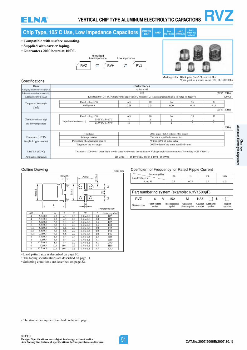
NOTEDesign, Specifications are subject to change without notice.Ask factory for technical specifications before purchase and/or use. CAT.No.2006/2007E(2006.10.1)
RVZVERTICAL CHIP TYPE ALUMINUM ELECTROLYTIC CAPACITORS
Chip Type, 105˚C Use, Low Impedance Capacitors
• Compatible with surface mounting.• Supplied with carrier taping.• Guarantees 2000 hours at 105˚C.
RVZ RVH
MiniturizedLow impedance
RVJ
Low impedance
L
D0.
5
B0.
2
(P)
(C)
(C)
0.4
0.2
A 0.2
( ): Reference size
0.3MAX
W
Specifications
Outline Drawing
Item PerformanceCategory temperature range (˚C)
Tolerance at rated capacitance (%)
Leakage current (µA)
Tangent of loss angle
(tan )
Characteristics at high
and low temperature
Endurance (105˚C)
(Applied ripple current)
Shelf life (105˚ SIJotgnidroccA:tnemtaertnoitacilppaegatloV.ecnarudneehtrofesohtsaemasehterasmetirehto;sruoh0001:emittseT)C C5101-1
Applicable standards JIS C5101-1, -18 1998 (IEC 60384-1 1992, -18 1993)
55 to 105
20
Less than 0.01CV or 3 whichever is larger (after 2 minutes) C: Rated capacitance(µF); V: Rated voltage(V)
535261013.6)V(egatlovdetaR
0.28 0.24 0.20 0.16 0.14tan (max.)
(20˚C)
(20˚C,120Hz)
(20˚C,120Hz)
(120Hz)
Test time
Leakage current
Percentage of capacitance change
Tangent of the loss angle
2000 hours (8x6.5 or less: 1000 hours)
The initial specified value or less
Within 25% of initial value
200% or less of the initial specified value
535261013.6)V(egatlovdetaR
4 3 2 2 2
8 5 4 3 3Impedance ratio (max.)
25˚C / 20˚C
55˚C / 20˚C
Unit: mm
44556.36.36.3888
1010
ø D5.3 0.25.8 0.35.3 0.25.8 0.35.3 0.25.8 0.37.7 0.36.5 0.310 0.5
10.5 0.510 0.5
10.5 0.5
L4.34.35.35.36.66.66.68.48.48.4
10.410.4
4.34.35.35.36.66.66.68.48.48.4
10.410.4
A B2.02.02.32.32.72.72.73.43.03.03.33.3
1.01.01.51.52.02.02.02.33.13.14.74.7
C0.5 to 0.80.5 to 0.80.5 to 0.80.5 to 0.80.5 to 0.80.5 to 0.80.5 to 0.80.5 to 0.80.7 to 1.10.7 to 1.10.7 to 1.10.7 to 1.1
WD55D61E55E61F55F61F80G68G10GA5H10HA5
P Casing symbol
Coefficient of Frequency for Rated Ripple Current
Rated voltage(V)
Frequency(Hz)
6.3 to 35
120 1k 10k 100k
0.5 0.75 0.9 1.0
Marking color : Black print (ø4x5.3L – ø8x6.5L)White print on a brown sleeve (ø8x10L . ø10x10L)
• Land pattern size is described on page 10.• The taping spesifications are described on page 11.• Soldering conditions are described on page 32.
Part numbering system (example: 6.3V1500µF)
RVZ — V
Series code
6 152 MRated voltage
symbolRated capacitance
symbolCapacitance
tolerance symbol
HA5Casingsymbol
—Tapingsymbol
Additionalsymbol
U
• The standard ratings are described on the next page.
105˚C2000hours
LowImpedance
GREENCAP SMD
Anti-cleaningsolvent
®
Chip typeAlum
inum Electrolytic Capacitors
NOTEDesign, Specifications are subject to change without notice.Ask factory for technical specifications before purchase and/or use. 51 CAT.No.2007/2008E(2007.10.1)
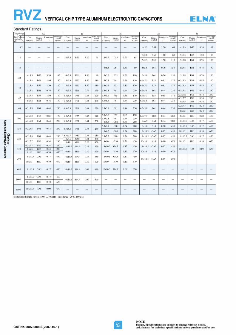
NOTEDesign, Specifications are subject to change without notice.Ask factory for technical specifications before purchase and/or use.CAT.No.2006/2007E(2006.10.1)
RVZ VERTICAL CHIP TYPE ALUMINUM ELECTROLYTIC CAPACITORS
Standard Ratings
(Note) Rated ripple current : 105˚C, 100kHz ; Impedance : 20˚C, 100kHz
4.7
10
15
22
33
47
68
100
150
220
330
470
680
1000
1500
Rated voltage(V) 6.3
ItemRatedcapacitance(µF)
— — — —
— — — —
— — — —
4x5.3 D55 3.20 65
4x5.8 D61 1.80 80
5x5.3 E55 1.50 110
5x5.8 E61 0.76 150
5x5.3 E55 1.50 110
5x5.8 E61 0.76 150
6.3x5.8 F61 0.44 230
6.3x5.3 F55 0.85 170
6.3x5.8 F61 0.44 230
6.3x5.8 F61 0.44 230
6.3x5.8 F61 0.44 230
6.3x7.7 F80 0.34 280
6.3x7.7 F80 0.34 280
8x6.5 G68 0.34 200
8x10 G10 0.20 450
8x10.5 GA5 0.17 450
10x10 H10 0.10 670
8x10.5 GA5 0.17 450
8x10.5 GA5 0.17 450
10x10 H10 0.10 670
10x10.5 HA5 0.09 670
— — — —
4x5.3 D55 3.20 65
— — — —
4x5.8 D61 1.80 80
5x5.3 E55 1.50 110
5x5.3 E55 1.50 110
5x5.8 E61 0.76 150
6.3x5.3 F55 0.85 170
6.3x5.8 F61 0.44 230
6.3x5.8 F61 0.44 230
6.3x5.3 F55 0.85 170
6.3x5.8 F61 0.44 230
6.3x5.8 F61 0.44 230
6.3x7.7 F80 0.34 280
8x6.5 G68 0.34 280
8x10 G10 0.20 450
8x10.5 GA5 0.17 450
10x10 H10 0.10 670
8x10.5 GA5 0.17 450
10x10 H10 0.10 670
10x10.5 HA5 0.09 670
10x10.5 HA5 0.09 670
— — — —
— — — —
4x5.3 D55 3.20 65
4x5.8 D61 1.80 80
5x5.3 E55 1.50 110
5x5.8 E61 0.76 150
6.3x5.3 F55 0.85 170
6.3x5.8 F61 0.44 230
6.3x5.3 F55 0.85 170
6.3x5.8 F61 0.44 230
6.3x5.8 F61 0.44 230
6.3x5.3 F55 0.85 170
6.3x5.8 F61 0.44 230
8x6.5 G68 0.34 280
6.3x7.7 F80 0.34 280
8x6.5 G68 0.34 280
6.3x7.7 F80 0.34 280
8x10 G10 0.20 450
8x10.5 GA5 0.17 450
10x10 H10 0.10 670
8x10.5 GA5 0.17 450
10x10 H10 0.10 670
10x10.5 HA5 0.09 670
— — — —
— — — —
4x5.3 D55 3.20 65
4x5.8 D61 1.80 80
5x5.3 E55 1.50 110
5x5.8 E61 0.76 150
5x5.8 E61 0.76 150
6.3x5.3 F55 0.85 170
6.3x5.3 F55 0.85 170
6.3x5.8 F61 0.44 230
6.3x5.3 F55 0.85 170
6.3x5.8 F61 0.44 230
6.3x5.8 F61 0.44 230
6.3x7.7 F80 0.34 280
8x6.5 G68 0.34 280
8x10 G10 0.20 450
8x10.5 GA5 0.17 450
8x10.5 GA5 0.17 450
10x10 H10 0.10 670
8x10.5 GA5 0.17 450
10x10 H10 0.10 670
10x10.5 HA5 0.09 670
— — — —
— — — —
— — — —
4x5.3 D55 3.20 65
5x5.3 E55 1.50 110
5x5.8 E61 0.76 150
5x5.8 E61 0.76 150
5x5.8 E61 0.76 150
6.3x5.3 F55 0.85 170
6.3x5.3 F55 0.85 170
6.3x5.8 F61 0.44 230
6.3x5.8 F61 0.44 230
6.3x7.7 F80 0.34 280
8x6.5 G68 0.34 280
6.3x7.7 F80 0.34 280
8x6.5 G68 0.34 280
8x10 G10 0.20 450
8x10.5 GA5 0.17 450
8x10.5 GA5 0.17 450
10x10 H10 0.10 670
8x10.5 GA5 0.17 450
10x10 H10 0.10 670
10x10.5 HA5 0.09 670
— — — —
— — — —
— — — —
— — — —
Case
ø D(mm)Casingsymbol
Impedance
mArms
Rated ripplecurrent Case
ø D(mm)Casingsymbol
Impedance
mArms
Rated ripplecurrent Case
ø D(mm)Casingsymbol
Impedance
mArms
Rated ripplecurrent Case
ø D(mm)Casingsymbol
Impedance
mArms
Rated ripplecurrent Case
ø D(mm)Casingsymbol
Impedance
mArms
Rated ripplecurrent
53526101
®
Chip typeAlum
inum Electrolytic Capacitors
NOTEDesign, Specifications are subject to change without notice.Ask factory for technical specifications before purchase and/or use.52CAT.No.2007/2008E(2007.10.1)
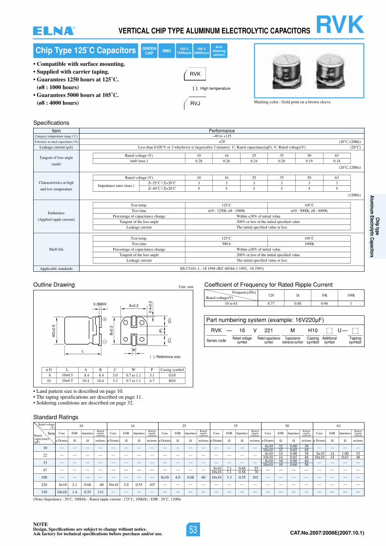
NOTEDesign, Specifications are subject to change without notice.Ask factory for technical specifications before purchase and/or use. CAT.No.2006/2007E(2006.10.1)
L
D0.
5
B0.
2
(P)
(C)
(C)
0.4
0.2
A 0.2
( ): Reference size
0.3MAX
W
Chip Type 125˚C Capacitors
• Compatible with surface mounting.• Supplied with carrier taping.• Guarantees 1250 hours at 125˚C.
(ø8 : 1000 hours)• Guarantees 5000 hours at 105˚C.
(ø8 : 4000 hours) Marking color : Gold print on a brown sleeve
RVK
RVJ
High temperature
Specifications
tnerruCelppiRdetaRrofycneuqerFfotneiciffeoCgniwarDeniltuO
Item PerformanceCategory temperature range (˚C)
Tolerance at rated capacitance (%)
Leakage current (µA)
Tangent of loss angle
(tan )
Characteristics at high
and low temperature
Endurance
(Applied ripple current)
Shelf life
Applicable standards JIS C5101-1, -18 1998 (IEC 60384-1 1992, -18 1993)
40 to 125
20
Less than 0.02CV or 3 whichever is larger(after 2 minutes) C: Rated capacitance(µF); V: Rated voltage(V)
360553526101)V(egatlovdetaR
0.28 0.26 0.24 0.20 0.19 0.18tan (max.)
(20˚C)
(20˚C,120Hz)
(20˚C,120Hz)
(120Hz)
Test temp.
Test time
Percentage of capacitance change
Tangent of the loss angle
Leakage current
125˚C
ø10 : 1250h, ø8 : 1000h
105˚C
ø10 : 5000h, ø8 : 4000h
Within 30% of initial value
300% or less of the initial specified value
The initial specified value or less
Test temp.
Test time
Percentage of capacitance change
Tangent of the loss angle
Leakage current
125˚C
500 h
105˚C
1000h
Within 20% of initial value
200% or less of the initial specified value
The initial specified value or less
360553526101)V(egatlovdetaR
3 3 3 3 3 3
5 5 5 5 5 5Impedance ratio (max.)
25˚C / 20˚C
40˚C / 20˚C
Unit: mm
Rated voltage(V)
Frequency(Hz)
10 to 63
120 1k 10k 100k
0.77 0.88 0.96 1
8
10
ø D10 0.5
10 0.5
L
8.4
10.4
8.4
10.4
A B
3.0
3.3
C
0.7 to 1.1
0.7 to 1.1
W
3.1
4.7
G10
H10
P Casing symbol
(Note) Impedance : 20˚C, 100kHz : Rated ripple current : 125˚C, 100kHz ; ESR : 20˚C, 120Hz
10
22
33
47
100
220
330
Rated voltage(V) 10
ItemRatedcapacitance(µF)
— — — —
— — — —
— — — —
— — — —
— — — —
8x10 2.1 0.68 60
10x10 1.4 0.55 111
— — — —
— — — —
— — — —
— — — —
8x10 4.0 0.68 60
— — — —
— — — —
— — — —
— — — —
— — — —
— — — —
— — — —
— — — —
— — — —
— — — —
— — — —
10x10 3.3 0.55 102
— — — —
— — — —
8x10 32 0.80 3810x10 32 0.65 458x10 14 0.80 38
10x10 14 0.65 488x10 10 0.80 40
10x10 10 0.60 58
8x10 14 1.00 3310x10 14 0.67 48
8x10 7.1 0.68 5510x10 7.1 0.58 70
— — — —
— — — —
— — — —
— — — —
— — — —
— — — —
— — — —
— — — —
— — — —
10x10 2.0 0.55 107
— — — —
Case ESR Impedance
ø D(mm) mArms
Ratedripplecurrent
Case ESR Impedance
ø D(mm) mArms
Ratedripplecurrent
Case ESR Impedance
ø D(mm) mArms
Ratedripplecurrent
Case ESR Impedance
ø D(mm) mArms
Ratedripplecurrent
Case ESR Impedance
ø D(mm) mArms
Ratedripplecurrent
Case ESR Impedance
ø D(mm) mArms
Ratedripplecurrent
3605535261
Standard Ratings
• Land pattern size is described on page 10.• The taping spesifications are described on page 11.• Soldering conditions are described on page 32.
Part numbering system (example: 16V220µF)
RVK — V
Series code
16 221 MRated voltage
symbolRated capacitance
symbolCapacitance
tolerance symbol
H10Casingsymbol
—Tapingsymbol
Additionalsymbol
U
RVKVERTICAL CHIP TYPE ALUMINUM ELECTROLYTIC CAPACITORS
GREENCAP SMD
Anti-cleaningsolvent
125˚C1250hours
105˚C5000hours
®
Chip typeAlum
inum Electrolytic Capacitors
NOTEDesign, Specifications are subject to change without notice.Ask factory for technical specifications before purchase and/or use. 53 CAT.No.2007/2008E(2007.10.1)
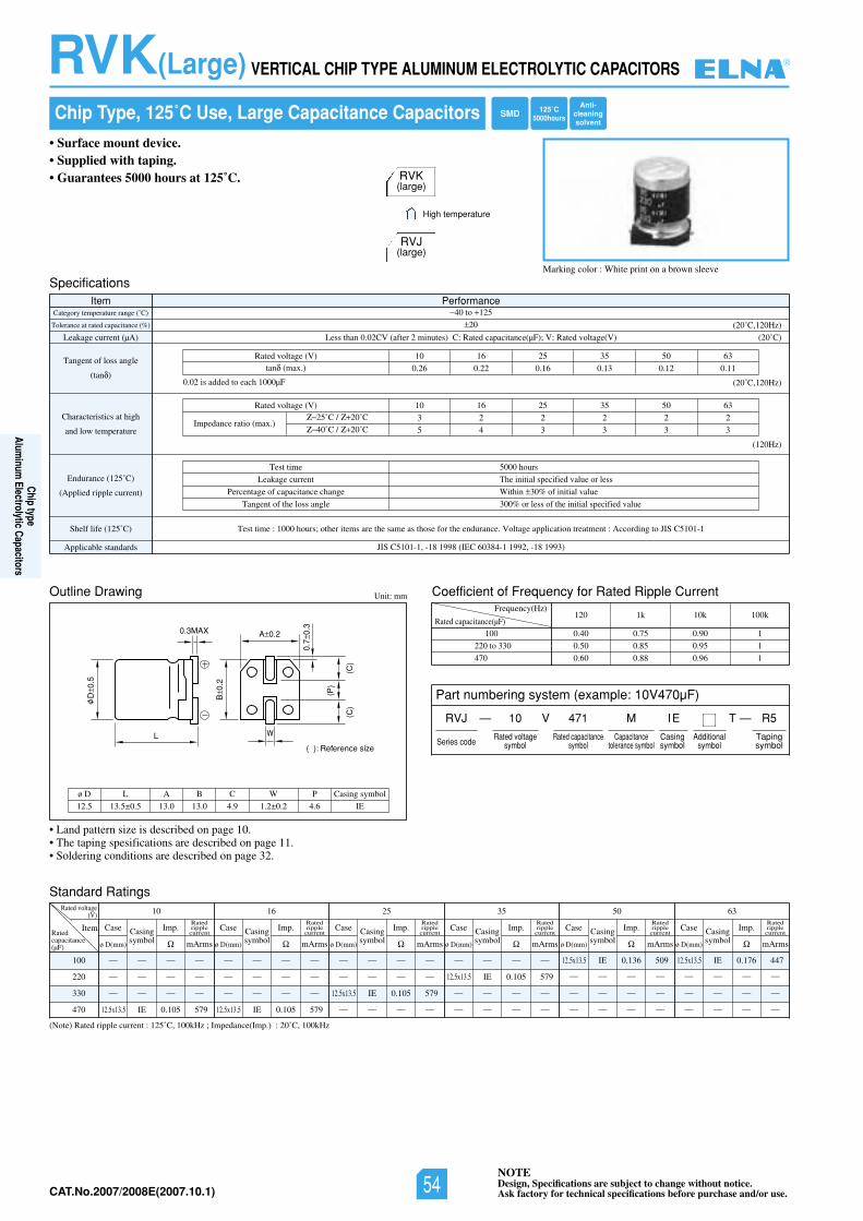
NOTEDesign, Specifications are subject to change without notice.Ask factory for technical specifications before purchase and/or use.CAT.No.2006/2007E(2006.10.1)
• Land pattern size is described on page 10.• The taping spesifications are described on page 11.• Soldering conditions are described on page 32.
Chip Type, 125˚C Use, Large Capacitance Capacitors
• Surface mount device.• Supplied with taping.• Guarantees 5000 hours at 125˚C.
Marking color : White print on a brown sleeve
Outline Drawing Unit: mm
RVK(large)
RVJ(large)
High temperature
SpecificationsItem Performance
Category temperature range (˚C)
Tolerance at rated capacitance (%)
Leakage current (µA)
Tangent of loss angle
(tan )
Characteristics at high
and low temperature
Endurance (125˚C)
(Applied ripple current)
Shelf life (125˚ SIJotgnidroccA:tnemtaertnoitacilppaegatloV.ecnarudneehtrofesohtsaemasehterasmetirehto;sruoh0001:emittseT)C C5101-1
Applicable standards JIS C5101-1, -18 1998 (IEC 60384-1 1992, -18 1993)
40 to 125
20
Less than 0.02CV (after 2 minutes) C: Rated capacitance(µF); V: Rated voltage(V)
360553526101)V(egatlovdetaR
0.26 0.22 0.16 0.13 0.12 0.11tan (max.)
(20˚C)
(20˚C,120Hz)
(20˚C,120Hz)
(120Hz)
Test time
Leakage current
Percentage of capacitance change
Tangent of the loss angle
5000 hours
The initial specified value or less
Within 30% of initial value
300% or less of the initial specified value
360553526101)V(egatlovdetaR
3 2 2 2 2 2
5 4 3 3 3 3Impedance ratio (max.)
25˚C / 20˚C
40˚C / 20˚C
0.02 is added to each 1000µF
(Note) Rated ripple current : 125˚C, 100kHz ; Impedance(Imp.) : 20˚C, 100kHz
100
220
330
470
Rated voltage(V) 10
ItemRatedcapacitance(µF)
— — — —
— — — —
— — — —
12.5x13.5 IE 0.105 579
— — — —
— — — —
— — — —
12.5x13.5 IE 0.105 579
— — — —
— — — —
12.5x13.5 IE 0.105 579
— — — —
— — — —
12.5x13.5 IE 0.105 579
— — — —
— — — —
12.5x13.5 IE 0.136 509
— — — —
— — — —
12.5x13.5 IE 0.176 447
— — — —
— — — — — — — —
— — — —
Case Imp.
ø D(mm) mArms
Ratedripplecurrent
3605535261
Standard Ratings
Casingsymbol
Case Imp.
ø D(mm) mArms
RatedripplecurrentCasing
symbol
Case Imp.
ø D(mm) mArms
RatedripplecurrentCasing
symbol
Case Imp.
ø D(mm) mArms
RatedripplecurrentCasing
symbol
Case Imp.
ø D(mm) mArms
RatedripplecurrentCasing
symbol
Case Imp.
ø D(mm) mArms
RatedripplecurrentCasing
symbol
L
D0.
5
B0.
2
(P)
(C)
(C)
0.7
0.3
A 0.20.3MAX
W
( ): Reference size
12.5
ø D
13.5±0.5
L
13.0 13.0
A B
4.9
C
1.2±0.2
W
4.6 IE
P Casing symbol
Coefficient of Frequency for Rated Ripple Current
Rated capacitance(µF)
Frequency(Hz)
100
220 to 330
470
120 1k 10k 100k
0.40 0.75 0.90 1
0.50 0.85 0.95 1
0.60 0.88 0.96 1
RVK(Large) VERTICAL CHIP TYPE ALUMINUM ELECTROLYTIC CAPACITORS
125˚C5000hoursSMD
Anti-cleaningsolvent
Part numbering system (example: 10V470µF)
— V TRVJ
Series code
10
Rated voltagesymbol
471
Rated capacitancesymbol
M
Capacitancetolerance symbol
IE
Casingsymbol
— R5
Tapingsymbol
Additionalsymbol
®
Chip typeAlum
inum Electrolytic Capacitors
NOTEDesign, Specifications are subject to change without notice.Ask factory for technical specifications before purchase and/or use.54CAT.No.2007/2008E(2007.10.1)
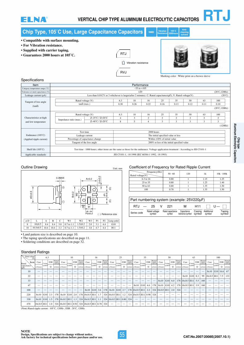
NOTEDesign, Specifications are subject to change without notice.Ask factory for technical specifications before purchase and/or use. CAT.No.2006/2007E(2006.10.1)
8
10
ø D10 0.5
10.5 0.5
L
8.4
10.4
8.4
10.4
A B
3.0
3.3
C
0.7 to 1.1
0.7 to 1.1
W1
G10
H11
Casing symbol
3.1
4.7
P1
4.4
4.4
P21.5 0.2
1.5 0.2
W2
2.0
3.0
W3
Standard Ratings
(Note) Rated ripple current : 105˚C, 120Hz ; ESR : 20˚C, 120Hz
10
22
33
47
100
220
330
470
Rated voltage(V) 6.3
ItemRatedcapacitance(µF)
— — — —
— — — —
— — — —
— — — —
— — — —
8x10 G10 2.3 178
8x10 G10 1.5 178
10x10.5 H11 1.0 324
Case
ø D(mm)
Casingsymbol
ESR
mArms
Ratedripplecurrent
10
— — — —
— — — —
— — — —
— — — —
— — — —
8x10 G10 2.0 178
10x10.5 H11 1.3 324
10x10.5 H11 0.92 324
Case
ø D(mm)
Casingsymbol
ESR
mArms
Ratedripplecurrent
16
— — — —
— — — —
— — — —
— — — —
8x10 G10 3.6 178
10x10.5 H11 1.7 324
10x10.5 H11 1.1 324
10x10.5 H11 0.78 324
Case
ø D(mm)
Casingsymbol
ESR
mArms
Ratedripplecurrent
25
— — — —
— — — —
— — — —
— — — —
8x10 G10 2.7 178
10x10.5 H11 1.2 324
10x10.5 H11 0.80 324
— — — —
— — — —
— — — —
— — — —
8x10 G10 4.6 178
10x10.5 H11 2.2 324
10x10.5 H11 0.98 324
— — — —
— — — —
— — — —
— — — —
8x10 G10 6.0 178
8x10 G10 4.2 178
10x10.5 H11 2.0 324
— — — —
— — — —
— — — —
— — — —
8x10 G10 8.3 99
10x10.5 H11 5.5 160
10x10.5 H11 3.9 160
— — — —
— — — —
— — — —
— — — —
8x10 G10 16.6 67
10x10.5 H11 7.5 133
— — — —
— — — —
— — — —
— — — —
— — — —
— — — —
Case
ø D(mm)
Casingsymbol
ESR
mArms
Ratedripplecurrent
35
Case
ø D(mm)
Casingsymbol
ESR
mArms
Ratedripplecurrent
50
Case
ø D(mm)
Casingsymbol
ESR
mArms
Ratedripplecurrent
63
Case
ø D(mm)
Casingsymbol
ESR
mArms
Ratedripplecurrent
100
Case
ø D(mm)
Casingsymbol
ESR
mArms
Ratedripplecurrent
RTJVERTICAL CHIP TYPE ALUMINUM ELECTROLYTIC CAPACITORS
Chip Type, 105˚C Use, Large Capacitance Capacitors
• Compatible with surface mounting.• For Vibration resistance.• Supplied with carrier taping.• Guarantees 2000 hours at 105˚C.
Marking color : White print on a brown sleeve
RTJ
RVJ
Vibration resistance
L
D0.
5
B0.
2
0.4
0.2
A 0.2
P2 0.2
0.3MAX
W1W3
W2
(P)
(C)
(C)
( ): Reference size
tnerruCelppiRdetaRrofycneuqerFfotneiciffeoCgniwarDeniltuO Unit: mm
Rated voltage(V)
Frequency(Hz)
6.3 to 16
25 to 35
50 to 63
100
50 . 60 120 1k 10k . 100k
0.80 1 1.15 1.25
0.80 1 1.25 1.40
0.80 1 1.35 1.50
0.70 1 1.35 1.50
SpecificationsItem Performance
Category temperature range (˚C)
Tolerance at rated capacitance (%)
Leakage current (µA)
Tangent of loss angle
(tan )
Characteristics at high
and low temperature
Endurance (105˚C)
(Applied ripple current)
Shelf life (105˚ SIJotgnidroccA:tnemtaertnoitacilppaegatloV.ecnarudneehtrofesohtsaemasehterasmetirehto;sruoh0001:emittseT)C C5101-1
Applicable standards JIS C5101-1, -18 1998 (IEC 60384-1 1992, -18 1993)
55 to 105
20
Less than 0.01CV or 3 whichever is larger(after 2 minutes) C: Rated capacitance(µF); V: Rated voltage(V)
0013605535261013.6)V(egatlovdetaR
0.30 0.26 0.22 0.16 0.13 0.12 0.11 0.10tan (max.)
(20˚C)
(20˚C,120Hz)
(20˚C,120Hz)
(120Hz)
Test time
Leakage current
Percentage of capacitance change
Tangent of the loss angle
2000 hours
The initial specified value or less
Within 20% of initial value
200% or less of the initial specified value
0013605535261013.6)V(egatlovdetaR
4 3 2 2 2 2 2 2
8 5 4 3 3 3 3 3Impedance ratio (max.)
25˚C / 20˚C
40˚C / 20˚C
• Land pattern size is described on page 10.• The taping spesifications are described on page 11.• Soldering conditions are described on page 32.
105˚C2000hoursSMD
Anti-cleaningsolvent
VibrationResistance
Part numbering system (example: 25V220µF)
RTJ — V
Series code
25 221 MRated voltage
symbolRated capacitance
symbolCapacitance
tolerance symbol
H11Casingsymbol
—Tapingsymbol
Additionalsymbol
U
®
Chip typeAlum
inum Electrolytic Capacitors
NOTEDesign, Specifications are subject to change without notice.Ask factory for technical specifications before purchase and/or use. 55 CAT.No.2007/2008E(2007.10.1)

NOTEDesign, Specifications are subject to change without notice.Ask factory for technical specifications before purchase and/or use.CAT.No.2006/2007E(2006.10.1)
RTH VERTICAL CHIP TYPE ALUMINUM ELECTROLYTIC CAPACITORS
Chip Type, 105˚C Use, Low Impedance Capacitors
• Compatible with surface mounting.• For Vibration resistance.• Supplied with carrier taping.• Guarantees 2000 hours at 105˚C.
Marking color : White print on a brown sleeve
RTH RVH
Vibration resistance
L
D0.
5
B0.
2
0.4
0.2
A 0.2
P2 0.2
0.3MAX
W1W3
W2
(P)
(C)
(C)
( ): Reference size
Specifications
Outline Drawing
Standard Ratings
Coefficient of Frequency for Rated Ripple Current
Item PerformanceCategory temperature range (˚C)
Tolerance at rated capacitance (%)
Leakage current (µA)
Tangent of loss angle
(tan )
Characteristics at high
and low temperature
Endurance (105˚C)
(Applied ripple current)
Shelf life (105˚ SIJotgnidroccA:tnemtaertnoitacilppaegatloV.ecnarudneehtrofesohtsaemasehterasmetirehto;sruoh0001:emittseT)C C5102
Applicable standards JIS C5101-1, -18 1998 (IEC 60384-1 1992, -18 1993)
55 to 105
20
Less than 0.01CV or 3 whichever is larger(after 2 minutes) C: Rated capacitance(µF); V: Rated voltage(V)
535261013.6)V(egatlovdetaR
0.30 0.26 0.22 0.16 0.13tan (max.)
(20˚C)
(20˚C,120Hz)
(20˚C,120Hz)
(120Hz)
Test time
Leakage current
Percentage of capacitance change
Tangent of the loss angle
2000 hours
The initial specified value or less
Within 20% of initial value
200% or less of the initial specified value
535261013.6)V(egatlovdetaR
4 3 2 2 2
8 5 4 3 3Impedance ratio (max.)
25˚C / 20˚C
40˚C / 20˚C
Unit: mm
Frequency (Hz)
Coefficient
50 . 60 120 1k 10k . 100k
0.64 0.8 0.93 1
8
10
ø D10 0.5
10.5 0.5
L
8.4
10.4
8.4
10.4
A B
3.0
3.3
C
0.7 to 1.1
0.7 to 1.1
W1
G10
H11
Casing symbol
3.1
4.7
P1
4.4
4.4
P21.5 0.2
1.5 0.2
W2
2.0
3.0
W3
(Note) Rated ripple current : 105˚C, 100kHz ; Impedance : 20˚C, 100kHz
47
100
220
330
470
Rated voltage(V) 6.3
ItemRatedcapacitance(µF)
— — — —
— — — —
— — — —
8x10 G10 0.45 369
— — — —
— — — —
— — — —
8x10 G10 0.45 369
— — — —
10x10.5 H11 0.25 553
— — — —
— — — —
— — — —
10x10.5 H11 0.25 553
— — — —
— — — —
8x10 G10 0.45 369
10x10.5 H11 0.25 553
— — — —
— — — —
8x10 G10 0.45 369
10x10.5 H11 0.25 553
— — — —
— — — —
— — — —
Case
ø D(mm)
Casingsymbol
Impedance
mArms
Rated ripplecurrent
10
Case
ø D(mm)
Casingsymbol
Impedance
mArms
Rated ripplecurrent
16
Case
ø D(mm)
Casingsymbol
Impedance
mArms
Rated ripplecurrent
25
Case
ø D(mm)
Casingsymbol
Impedance
mArms
Rated ripplecurrent
35
Case
ø D(mm)
Casingsymbol
Impedance
mArms
Rated ripplecurrent
• Land pattern size is described on page 10.• The taping spesifications are described on page 11.• Soldering conditions are described on page 32.
105˚C2000hoursSMD
Anti-cleaningsolvent
VibrationResistance
LowImpedance
Part numbering system (example: 25V100µF)
RTH — V
Series code
25 101 MRated voltage
symbolRated capacitance
symbolCapacitance
tolerance symbol
G10Casingsymbol
—Tapingsymbol
Additionalsymbol
U
®
Chip typeAlum
inum Electrolytic Capacitors
NOTEDesign, Specifications are subject to change without notice.Ask factory for technical specifications before purchase and/or use.56CAT.No.2007/2008E(2007.10.1)
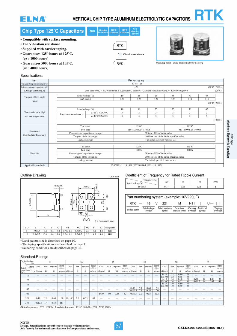
NOTEDesign, Specifications are subject to change without notice.Ask factory for technical specifications before purchase and/or use. CAT.No.2006/2007E(2006.10.1)
L
D0.
5
B0.
2
0.4
0.2
A 0.2
P2 0.2
0.3MAX
W1W3
W2
(P)
(C)
(C)
( ): Reference size
8
10
ø D10 0.5
10.5 0.5
L
8.4
10.4
8.4
10.4
A B
3.0
3.0
C
0.7 to 1.1
0.7 to 1.1
W1
G10
H11
Casing symbol
3.1
4.7
P1
4.4
4.4
P21.5 0.2
1.5 0.2
W2
2.0
3.0
W3
RTKVERTICAL CHIP TYPE ALUMINUM ELECTROLYTIC CAPACITORS
Chip Type 125˚C Capacitors
• Compatible with surface mounting.• For Vibration resistance.• Supplied with carrier taping.• Guarantees 1250 hours at 125˚C.
(ø8 : 1000 hours)• Guarantees 5000 hours at 105˚C.
(ø8 : 4000 hours)
Marking color : Gold print on a brown sleeve
RTK
RVK
Vibration resistance
Specifications
tnerruCelppiRdetaRrofycneuqerFfotneiciffeoCgniwarDeniltuO
Item PerformanceCategory temperature range (˚C)
Tolerance at rated capacitance (%)
Leakage current (µA)
Tangent of loss angle
(tan )
Characteristics at high
and low temperature
Endurance
(Applied ripple current)
Shelf life
Applicable standards JIS C5101-1, -18 1998 (IEC 60384-1 1992, -18 1993)
40 to 125
20
Less than 0.02CV or 3 whichever is larger(after 2 minutes) C: Rated capacitance(µF); V: Rated voltage(V)
360553526101)V(egatlovdetaR
0.28 0.26 0.24 0.20 0.19 0.18tan (max.)
(20˚C)
(20˚C,120Hz)
(20˚C,120Hz)
(120Hz)
Test temp.
Test time
Percentage of capacitance change
Tangent of the loss angle
Leakage current
125˚C
ø10 : 1250h, ø8 : 1000h
105˚C
ø10 : 5000h, ø8 : 4000h
Within 30% of initial value
300% or less of the initial specified value
The initial specified value or less
Test temp.
Test time
Percentage of capacitance change
Tangent of the loss angle
Leakage current
125˚C
500 h
105˚C
1000h
Within 20% of initial value
200% or less of the initial specified value
The initial specified value or less
360553526101)V(egatlovdetaR
3 3 3 3 3 3
5 5 5 5 5 5Impedance ratio (max.)
25˚C / 20˚C
40˚C / 20˚C
Unit: mm
Rated voltage(V)
Frequency(Hz)
10 to 63
120 1k 10k 100k
0.77 0.88 0.96 1
Standard Ratings
(Note) Impedance : 20˚C, 100kHz : Rated ripple current : 125˚C, 100kHz ; ESR : 20˚C, 120Hz
10
22
33
47
100
220
330
Rated voltage(V) 10
ItemRatedcapacitance(µF)
— — — —
— — — —
— — — —
— — — —
— — — —
8x10 2.1 0.68 60
10x10.5 1.4 0.55 111
— — — —
— — — —
— — — —
— — — —
8x10 4.0 0.68 60
— — — —
— — — —
— — — —
— — — —
— — — —
— — — —
— — — —
— — — —
— — — —
— — — —
— — — —
10x10.5 3.3 0.55 102
— — — —
— — — —
8x10 32 0.80 3810x10.5 32 0.65 458x10 14 0.80 38
10x10.5 14 0.65 488x10 10 0.80 40
10x10.5 10 0.60 58
8x10 14 1.00 3310x10.5 14 0.67 48
8x10 7.1 0.68 5510x10.5 7.1 0.58 70
— — — —
— — — —
— — — —
— — — —
— — — —
— — — —
— — — —
— — — —
— — — —
10x10.5 2.0 0.55 107
— — — —
Case ESR Impedance
ø D(mm) mArms
Ratedripplecurrent
Case ESR Impedance
ø D(mm) mArms
Ratedripplecurrent
Case ESR Impedance
ø D(mm) mArms
Ratedripplecurrent
Case ESR Impedance
ø D(mm) mArms
Ratedripplecurrent
Case ESR Impedance
ø D(mm) mArms
Ratedripplecurrent
Case ESR Impedance
ø D(mm) mArms
Ratedripplecurrent
3605535261
• Land pattern size is described on page 10.• The taping spesifications are described on page 11.• Soldering conditions are described on page 32.
SMDAnti-
cleaningsolvent
VibrationResistance
105˚C5000hours
125˚C1250hours
Part numbering system (example: 16V220µF)
RTK — V
Series code
16 221 MRated voltage
symbolRated capacitance
symbolCapacitance
tolerance symbol
H11Casingsymbol
—Tapingsymbol
Additionalsymbol
U
®
Chip typeAlum
inum Electrolytic Capacitors
NOTEDesign, Specifications are subject to change without notice.Ask factory for technical specifications before purchase and/or use. 57 CAT.No.2007/2008E(2007.10.1)
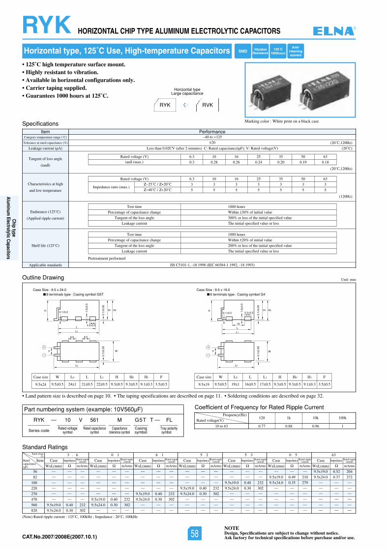
NOTEDesign, Specifications are subject to change without notice.Ask factory for technical specifications before purchase and/or use.CAT.No.2006/2007E(2006.10.1)
Part numbering system (example: 10V560µF)
RYK — V
Series code
10 561 M
Rated voltagesymbol
Rated capacitancesymbol
Capacitancetolerance symbol
G5T FLT —
Casingsymbol
Tray polaritysymbol
(Note) Rated ripple current : 125˚C, 100kHz ; Impedance : 20˚C, 100kHz
RYK HORIZONTAL CHIP TYPE ALUMINUM ELECTROLYTIC CAPACITORS
L0
W
L1
L
F
H H0H1
0.1
0.05
0.1
0.05
0.1 0.2 1.5
0.3
2.0 0.5
L0
W
L1
L
10
6.5 6.5
F
H H0H1
0.1
0.05
0.1
0.05
0.1 0.2
1.5
0.3
2.0 0.5
Case Size : 9.5 x 24.0 Case Size : 9.5 x 19.08 terminals type : Casing symbol G5T 6 terminals type : Casing symbol G4
Outline Drawing
Coefficient of Frequency for Rated Ripple Current
Unit: mm
Rated voltage(V)
Frequency(Hz)
10 to 63
120 1k 10k 100k
0.77 0.88 0.96 1
9.5x24
Case size L0
9.5 0.5
W
24 1
L
21 0.5
L1
9.3 0.5 9.3 0.5
H0
9.1 0.3 3.5 0.5
H1 F
• 125˚C high temperature surface mount.• Highly resistant to vibration.• Available in horizontal configurations only.• Carrier taping supplied.• Guarantees 1000 hours at 125˚C.
Marking color : White print on a black case
RYK RVK
Horizontal typeLarge capacitance
SpecificationsItem Performance
Category temperature range (˚C)
Tolerance at rated capacitance (%)
Leakage current (µA)
Tangent of loss angle
(tan )
Characteristics at high
and low temperature
Endurance (125˚C)
(Applied ripple current)
Shelf life (125˚C)
Pretreatment performed
Applicable standards JIS C5101-1, -18 1998 (IEC 60384-1 1992, -18 1993)
40 to 125
20
02()V(egatlovdetaR:V;)Fµ(ecnaticapacdetaR:C)setunim2retfa(VC20.0nahtsseL ˚C)
(20˚C,120Hz)
Test time
Percentage of capacitance change
Tangent of the loss angle
Leakage current
1000 hours
Within 30% of initial value
300% or less of the initial specified value
The initial specified value or less
Test time
Percentage of capacitance change
Tangent of the loss angle
Leakage current
1000 hours
Within 20% of initial value
200% or less of the initial specified value
The initial specified value or less
3605535261013.6)V(egatlovdetaR
0.3 0.28 0.26 0.24 0.20 0.19 0.18tan (max.)
(20˚C,120Hz)
(120Hz)
3605535261013.6)V(egatlovdetaR
3 3 3 3 3 3 3
5 5 5 5 5 5 5Impedance ratio (max.)
25˚C / 20˚C
40˚C / 20˚C
Horizontal type, 125˚C Use, High-temperature Capacitors
22 0.5
H
9.5x19
Case size L0
9.5 0.5
W
19 1
L
16 0.5
L1
9.3 0.5 9.3 0.5
H0
9.1 0.3 3.5 0.5
H1 F
17 0.5
H
Standard Ratings
Item
Rated voltage(V)
Ratedcapacitance(µF)
630 55 35 26 10 13 . 6
Case
WxL(mm)
Impedance
mArms
Rated ripplecurrent
56
82
100
220
270
470
560
820
— — —
— — —
— — —
— — —
— — —
— — —
9.5x19.0 0.40 232
9.5x24.0 0.30 302
— — —
— — —
— — —
— — —
— — —
9.5x19.0 0.40 232
9.5x24.0 0.30 302— — —
— — —
— — —
— — —
— — —
9.5x19.0 0.40 232
9.5x24.0 0.30 302— — —
— — —
— — —
— — —
— — —
9.5x19.0 0.40 232
9.5x24.0 0.30 302— — —
— — —
— — —
— — —
— — —
9.5x19.0 0.40 232
9.5x24.0 0.30 302— — —
— — —
— — —
— — —
— — —
9.5x19.0 0.49 210
9.5x24.0 0.35 279— — —
— — —
— — —
— — —
— — —
9.5x19.0 0.52 204
9.5x24.0 0.37 272— — —
— — —
— — —
— — —
— — —
— — —
Case
WxL(mm)
Impedance
mArms
Rated ripplecurrent Case
WxL(mm)
Impedance
mArms
Rated ripplecurrent Case
WxL(mm)
Impedance
mArms
Rated ripplecurrent Case
WxL(mm)
Impedance
mArms
Rated ripplecurrent Case
WxL(mm)
Impedance
mArms
Rated ripplecurrent Case
WxL(mm)
Impedance
mArms
Rated ripplecurrent
• Land pattern size is described on page 10. • The taping spesifications are described on page 11. • Soldering conditions are described on page 32.
SMDAnti-
cleaningsolvent
VibrationResistance
125˚C1000hours
®
Chip typeAlum
inum Electrolytic Capacitors
NOTEDesign, Specifications are subject to change without notice.Ask factory for technical specifications before purchase and/or use.58CAT.No.2007/2008E(2007.10.1)
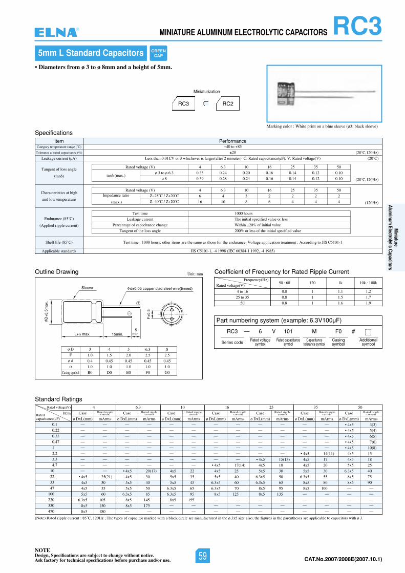
NOTEDesign, Specifications are subject to change without notice.Ask factory for technical specifications before purchase and/or use. CAT.No.2006/2007E(2006.10.1)
L max. 15min.
Sleeve
D0.
5max
.
F0.
5
d 0.05 copper clad steel wire(tinned)
5min.
RC3MINIATURE ALUMINUM ELECTROLYTIC CAPACITORS
Outline Drawing
Standard Ratings
Coefficient of Frequency for Rated Ripple CurrentUnit: mm
Rated voltage(V)
Frequency(Hz)
4 to 16
25 to 35
50
(Note) Rated ripple current : 85˚C, 120Hz ; The types of capacitor marked with a black circle are manufactured in the ø 3x5 size also; the figures in the parentheses are applicable to capacitors with ø 3.
50 . 60 120 1k 10k . 100k
0.8 1 1.1 1.2
0.8 1 1.5 1.7
0.8 1 1.6 1.9
0.1
0.22
0.33
0.47
1
2.2
3.3
4.7
10
22
33
47
100
220
330
470
Rated voltage(V) 6.3 05535261014
ItemRatedcapacitance(µF)
— —
— —
— —
— —
— —
— —
— —
— —
— —
• 4x5 25(21)
4x5 30
4x5 35
5x5 60
6.3x5 105
8x5 150
8x5 180
Case
ø DxL(mm) mArms
Rated ripplecurrent
— —
— —
— —
— —
— —
— —
— —
— —
• 4x5 20(17)
4x5 30
5x5 40
5x5 50
6.3x5 85
8x5 145
8x5 175— —
Case
ø DxL(mm) mArms
Rated ripplecurrent
— —
— —
— —
— —
— —
— —
— —
— —
4x5 22
5x5 35
5x5 45
6.3x5 65
6.3x5 95
8x5 155— —
— —
Case
ø DxL(mm) mArms
Rated ripplecurrent
— —
— —
— —
— —
— —
— —
— —
• 4x5 17(14)
4x5 25
5x5 40
6.3x5 60
6.3x5 70
8x5 125— —
— —
— —
Case
ø DxL(mm) mArms
Rated ripplecurrent
— —
— —
— —
— —
— —
— —
• 4x5 15(13)
4x5 18
5x5 30
6.3x5 50
6.3x5 65
8x5 95
8x5 135— —
— —
— —
Case
ø DxL(mm) mArms
Rated ripplecurrent
— —
— —
— —
— —
— —
• 4x5 14(11)
4x5 17
4x5 20
5x5 30
6.3x5 55
8x5 80
8x5 100— —
— —
— —
— —
Case
ø DxL(mm) mArms
Rated ripplecurrent
• 4x5 3(3)
• 4x5 5(4)
• 4x5 6(5)
• 4x5 7(6)
• 4x5 10(8)
4x5 15
4x5 18
5x5 25
6.3x5 40
8x5 75
8x5 90— —
— —
— —
— —
— —
Case
ø DxL(mm) mArms
Rated ripplecurrent
ø D
F
ø d
Casing symbol
3 4 5 6.3 8
1.0 1.5 2.0 2.5 2.5
0.4 0.45 0.45 0.45 0.45
1.0 1.0 1.0 1.0 1.0
B0 D0 E0 F0 G0
5mm L Standard Capacitors
Marking color : White print on a blue sleeve (ø3: black sleeve)
• Diameters from ø 3 to ø 8mm and a height of 5mm.
RC3 RC2
Miniaturization
SpecificationsItem Performance
Category temperature range (˚C)
Tolerance at rated capacitance (%)
Leakage current (µA)
Tangent of loss angle
(tan )
Characteristics at high
and low temperature
Endurance (85˚C)
(Applied ripple current)
Shelf life (85˚ SIJotgnidroccA:tnemtaertnoitacilppaegatloV.ecnarudneehtrofesohtsaemasehterasmetirehto;sruoh0001:emittseT)C C5101-1
Applicable standards JIS C5101-1, -4 1998 (IEC 60384-1 1992, -4 1985)
40 to 85
20
02()V(egatlovdetaR:V;)Fµ(ecnaticapacdetaR:C)setunim2retfa(regralsirevehcihw3roVC10.0nahtsseL ˚C)
(20˚C,120Hz)
(20˚C,120Hz)
(120Hz)
Test time
Leakage current
Percentage of capacitance change
Tangent of the loss angle
1000 hours
The initial specified value or less
Within 20% of initial value
200% or less of the initial specified value
05535261013.64)V(egatlovdetaR
0.35 0.24 0.20 0.16 0.14 0.12 0.10
0.39 0.28 0.24 0.16 0.14 0.12 0.10tan (max.)
ø 3 to ø 6.3
ø 8
05535261013.64)V(egatlovdetaR
6 4 3 2 2 2 2
16 10 8 6 4 4 4
Impedance ratio
(max.)
25˚C / 20˚C
40˚C / 20˚C
Part numbering system (example: 6.3V100µF)
RC3 — V
Series code
6 101 M
Rated voltagesymbol
Rated capacitancesymbol
Capacitancetolerance symbol
F0
Casingsymbol
#
Additionalsymbol
GREENCAP
®
Miniature
Aluminum
Electrolytic Capacitors
NOTEDesign, Specifications are subject to change without notice.Ask factory for technical specifications before purchase and/or use. 59 CAT.No.2007/2008E(2007.10.1)
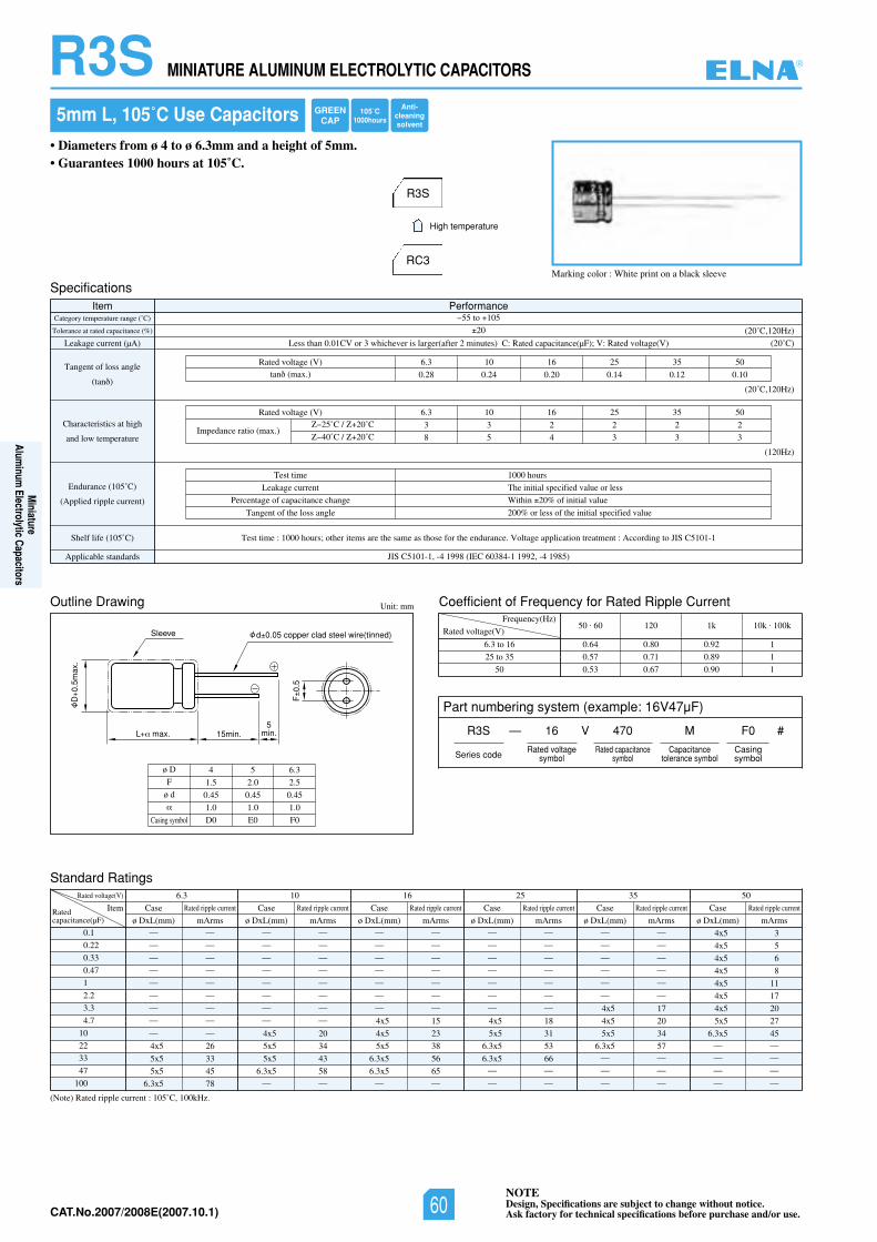
NOTEDesign, Specifications are subject to change without notice.Ask factory for technical specifications before purchase and/or use.CAT.No.2006/2007E(2006.10.1)
L max. 15min.
Sleeve
D0.
5max
.
F0.
5
d 0.05 copper clad steel wire(tinned)
5min.
R3S MINIATURE ALUMINUM ELECTROLYTIC CAPACITORS
Standard Ratings
ø D
F
ø d
4 5 6.3
1.5 2.0 2.5
0.45 0.45 0.45
1.0 1.0 1.0
D0 E0 F0
5mm L, 105˚C Use Capacitors
• Diameters from ø 4 to ø 6.3mm and a height of 5mm.• Guarantees 1000 hours at 105˚C.
Marking color : White print on a black sleeve
R3S
RC3
High temperature
Specifications
Outline Drawing
Item PerformanceCategory temperature range (˚C)
Tolerance at rated capacitance (%)
Leakage current (µA)
Tangent of loss angle
(tan )
Characteristics at high
and low temperature
Endurance (105˚C)
(Applied ripple current)
Shelf life (105˚ SIJotgnidroccA:tnemtaertnoitacilppaegatloV.ecnarudneehtrofesohtsaemasehterasmetirehto;sruoh0001:emittseT)C C5101-1
Applicable standards JIS C5101-1, -4 1998 (IEC 60384-1 1992, -4 1985)
55 to 105
20
Less than 0.01CV or 3 whichever is larger(after 2 minutes) C: Rated capacitance(µF); V: Rated voltage(V)
05535261013.6)V(egatlovdetaR
0.28 0.24 0.20 0.14 0.12 0.10tan (max.)
(20˚C)
(20˚C,120Hz)
(20˚C,120Hz)
(120Hz)
Test time
Leakage current
Percentage of capacitance change
Tangent of the loss angle
1000 hours
The initial specified value or less
Within 20% of initial value
200% or less of the initial specified value
05535261013.6)V(egatlovdetaR
3 3 2 2 2 2
8 5 4 3 3 3Impedance ratio (max.)
25˚C / 20˚C
40˚C / 20˚C
Unit: mm Coefficient of Frequency for Rated Ripple Current
Rated voltage(V)
Frequency(Hz)
6.3 to 16
25 to 35
50
50 . 60 120 1k 10k . 100k
0.64 0.80 0.92 1
0.57 0.71 0.89 1
0.53 0.67 0.90 1
(Note) Rated ripple current : 105˚C, 100kHz.
0.1
0.22
0.33
0.47
1
2.2
3.3
4.7
10
22
33
47
100
Rated voltage(V) 05535261013.6
ItemRatedcapacitance(µF)
— —
— —
— —
— —
— —
— —
— —
— —
— —
4x5 26
5x5 33
5x5 45
6.3x5 78
Case
ø DxL(mm) mArms
Rated ripple current
— —
— —
— —
— —
— —
— —
— —
— —
4x5 20
5x5 34
5x5 43
6.3x5 58— —
Case
ø DxL(mm) mArms
Rated ripple current
— —
— —
— —
— —
— —
— —
— —
4x5 15
4x5 23
5x5 38
6.3x5 56
6.3x5 65— —
Case
ø DxL(mm) mArms
Rated ripple current
— —
— —
— —
— —
— —
— —
— —
4x5 18
5x5 31
6.3x5 53
6.3x5 66— —
— —
Case
ø DxL(mm) mArms
Rated ripple current
— —
— —
— —
— —
— —
— —
4x5 17
4x5 20
5x5 34
6.3x5 57— —
— —
— —
Case
ø DxL(mm) mArms
Rated ripple current
4x5 3
4x5 5
4x5 6
4x5 8
4x5 11
4x5 17
4x5 20
5x5 27
6.3x5 45— —
— —
— —
— —
Case
ø DxL(mm) mArms
Rated ripple current
Casing symbol
Part numbering system (example: 16V47µF)
R3S — V
Series code
16 470 M
Rated voltagesymbol
Rated capacitancesymbol
Capacitancetolerance symbol
F0
Casingsymbol
#
GREENCAP
105˚C1000hours
Anti-cleaningsolvent
®
Miniature
Aluminum
Electrolytic Capacitors
NOTEDesign, Specifications are subject to change without notice.Ask factory for technical specifications before purchase and/or use.60CAT.No.2007/2008E(2007.10.1)
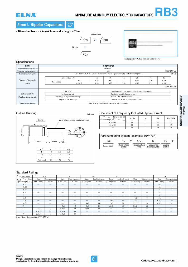
NOTEDesign, Specifications are subject to change without notice.Ask factory for technical specifications before purchase and/or use. CAT.No.2006/2007E(2006.10.1)
RB3MINIATURE ALUMINUM ELECTROLYTIC CAPACITORS
Outline Drawing
Standard Ratings
Coefficient of Frequency for Rated Ripple CurrentUnit: mm
Rated voltage(V)
Frequency(Hz)
6.3 to 16
25 to 35
50
50 . 60 120 1k 10k . 100k
0.8 1 1.1 1.2
0.8 1 1.5 1.7
0.8 1 1.6 1.9
Marking color : White print on a blue sleeve
• Diameters from ø 4 to ø 6.3mm and a height of 5mm.
RB2
Low Profile
5mm L Bipolar Capacitors
RB3
RC3
Bipolar
SpecificationsItem Performance
Category temperature range (˚C)
Tolerance at rated capacitance (%)
Leakage current (µA)
Tangent of loss angle
(tan )
Endurance (85˚C)
(Applied ripple current)
Applicable standards JIS C5101-1, -4 1998 (IEC 60384-1 1992, -4 1985)
40 to 85
20
Less than 0.03CV 3 (after 5 minutes) C: Rated capacitance(µF); V: Rated voltage(V)
05535261013.6)V(egatlovdetaR
0.35 0.30 0.25 0.20 0.20 0.20
0.30 0.25 0.20 0.15 0.15 0.15tan (max.)
(20˚C)
(20˚C,120Hz)
(20˚C,120Hz)
Test time
Leakage current
Percentage of capacitance change
Tangent of the loss angle
1000 hours (with the polarity inverted every 250 hours)
The initial specified value or less
Within 20% of initial value
200% or less of the initial specified value
ø 4
ø 5, 6.3
(Note) Rated ripple current : 85˚C, 120Hz.
0.1
0.22
0.33
0.47
1
2.2
3.3
4.7
10
22
33
47
Rated voltage(V) 05535261013.6
ItemRatedcapacitance(µF)
— —
— —
— —
— —
— —
— —
— —
— —
— —
5x5 31
6.3x5 45
6.3x5 54
Case
ø DxL(mm) mArms
Rated ripple current
— —
— —
— —
— —
— —
— —
— —
— —
4x5 18
6.3x5 40
6.3x5 49
6.3x5 59
Case
ø DxL(mm) mArms
Rated ripple current
— —
— —
— —
— —
— —
— —
— —
4x5 14
5x5 26
6.3x5 45— —
— —
Case
ø DxL(mm) mArms
Rated ripple current
— —
— —
— —
— —
— —
— —
4x5 13
5x5 21
6.3x5 35— —
— —
— —
Case
ø DxL(mm) mArms
Rated ripple current
— —
— —
— —
— —
— —
4x5 11
5x5 17
6.3x5 24
6.3x5 35— —
— —
— —
Case
ø DxL(mm) mArms
Rated ripple current
4x5 2
4x5 3
4x5 4
4x5 5
4x5 7
5x5 14
6.3x5 20
6.3x5 24— —
— —
— —
— —
Case
ø DxL(mm) mArms
Rated ripple current
L max. 15min.
Sleeve
D0.
5max
.
F0.
5
d 0.05 copper clad steel wire(tinned)
5min.
ø D
F
ø d
4 5 6.3
1.5 2.0 2.5
0.45 0.45 0.45
1.0 1.0 1.0
D0 E0 F0Casing symbol
Part numbering system (example: 10V47µF)
RB3 — V
Series code
10 470 M
Rated voltagesymbol
Rated capacitancesymbol
Capacitancetolerance symbol
F0
Casingsymbol
#
GREENCAP
®
Miniature
Aluminum
Electrolytic Capacitors
NOTEDesign, Specifications are subject to change without notice.Ask factory for technical specifications before purchase and/or use. 61 CAT.No.2007/2008E(2007.10.1)
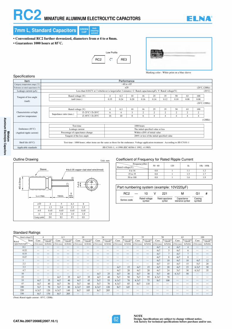
NOTEDesign, Specifications are subject to change without notice.Ask factory for technical specifications before purchase and/or use.CAT.No.2006/2007E(2006.10.1)
RC2 MINIATURE ALUMINUM ELECTROLYTIC CAPACITORS
Coefficient of Frequency for Rated Ripple Current
Rated voltage(V)
Frequency(Hz)
4 to 16
25 to 35
50 to 100
50 . 60 120 1k 10k . 100k
0.8 1 1.1 1.2
0.8 1 1.5 1.7
0.8 1 1.6 1.9
(Note) Rated ripple current : 85˚C, 120Hz.
0.1
0.22
0.33
0.47
1
2.2
3.3
4.7
10
22
33
47
100
220
330
Rated voltage(V) 4 6.3 10 16 25 35 50 63 100
ItemRatedcapacitance(µF)
— —
— —
— —
— —
— —
— —
— —
— —
— —
— —
4x7 35
4x7 40
5x7 70
6.3x7 120
8x7 170
Case
ø DxL(mm) mArms
Rated ripplecurrent
— —
— —
— —
— —
— —
— —
— —
— —
— —
4x7 35
4x7 40
4x7 50
5x7 80
6.3x7 140
8x7 205
Case
ø DxL(mm) mArms
Rated ripplecurrent
— —
— —
— —
— —
— —
— —
— —
— —
— —
4x7 35
4x7 45
5x7 60
6.3x7 105
8x7 185— —
Case
ø DxL(mm) mArms
Rated ripplecurrent
— —
— —
— —
— —
— —
— —
— —
— —
4x7 25
4x7 40
5x7 55
5x7 70
6.3x7 120
8x7 205— —
Case
ø DxL(mm) mArms
Rated ripplecurrent
— —
— —
— —
— —
— —
— —
4x7 15
4x7 20
4x7 30
5x7 50
6.3x7 70
6.3x7 85
8x7 145— —
— —
Case
ø DxL(mm) mArms
Rated ripplecurrent
— —
— —
— —
— —
— —
— —
4x7 15
4x7 20
4x7 30
5x7 55
6.3x7 75
8x7 110— —
— —
— —
Case
ø DxL(mm) mArms
Rated ripplecurrent
4x7 4
4x7 5
4x7 7
4x7 8
4x7 10
4x7 15
4x7 20
4x7 24
5x7 40
6.3x7 70
8x7 100— —
— —
— —
— —
Case
ø DxL(mm) mArms
Rated ripplecurrent
4x7 4
4x7 6
4x7 7
4x7 8
4x7 10
4x7 15
4x7 23
5x7 30
6.3x7 50— —
— —
— —
— —
— —
— —
Case
ø DxL(mm) mArms
Rated ripplecurrent
— —
— —
— —
— —
4x7 12
5x7 20
6.3x7 30
6.3x7 35— —
— —
— —
— —
— —
— —
— —
Case
ø DxL(mm) mArms
Rated ripplecurrent
7mm L, Standard Capacitors
Marking color : White print on a blue sleeve
• Conventional RC2 further downsized, diameters from ø 4 to ø 8mm.• Guarantees 1000 hours at 85˚C.
RC2 RE3
Low Profile
Specifications
Outline Drawing
Standard Ratings
Item PerformanceCategory temperature range (˚C)
Tolerance at rated capacitance (%)
Leakage current (µA)
Tangent of loss angle
(tan )
Characteristics at high
and low temperature
Endurance (85˚C)
(Applied ripple current)
Shelf life (85˚ SIJotgnidroccA:tnemtaertnoitacilppaegatloV.ecnarudneehtrofesohtsaemasehterasmetirehto;sruoh0001:emittseT)C C5101-1
Applicable standards JIS C5101-1, -4 1998 (IEC 60384-1 1992, -4 1985)
40 to 85
20
Less than 0.01CV or 3 whichever is larger(after 2 minutes) C: Rated capacitance(µF); V: Rated voltage(V)
0013605535261013.64)V(egatlovdetaR
0.35 0.24 0.20 0.16 0.14 0.12 0.10 0.08 0.08tan (max.)
(20˚C)
(20˚C,120Hz)
(20˚C,120Hz)
(120Hz)
Test time
Leakage current
Percentage of capacitance change
Tangent of the loss angle
1000 hours
The initial specified value or less
Within 20% of initial value
200% or less of the initial specified value
0013605535261013.64)V(egatlovdetaR
6 4 3 2 2 2 2 2 2
16 10 8 6 4 4 4 4 4Impedance ratio (max.)
25˚C / 20˚C
40˚C / 20˚C
Unit: mm
L max. 15min.
Sleeve
D0.
5max
.
F0.
5
d 0.05 copper clad steel wire(tinned)
5min.
ø D
F
ø d
4 5 6.3 8
1.5 2.0 2.5 3.5
0.45 0.45 0.45 0.45
1.0 1.0 1.0 1.0
D1 E1 F1 G1Casing symbol
Part numbering system (example: 10V220µF)
RC2 — V
Series code
10 221 M
Rated voltagesymbol
Rated capacitancesymbol
Capacitancetolerance symbol
G1
Casingsymbol
#
GREENCAP
Anti-cleaningsolvent
®
Miniature
Aluminum
Electrolytic Capacitors
NOTEDesign, Specifications are subject to change without notice.Ask factory for technical specifications before purchase and/or use.62CAT.No.2007/2008E(2007.10.1)
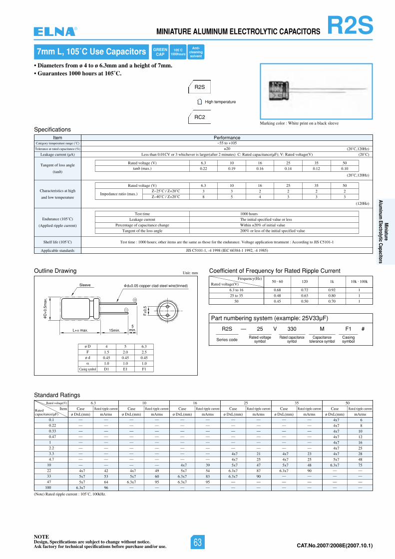
NOTEDesign, Specifications are subject to change without notice.Ask factory for technical specifications before purchase and/or use. CAT.No.2006/2007E(2006.10.1)
R2SMINIATURE ALUMINUM ELECTROLYTIC CAPACITORS
Standard Ratings
7mm L, 105˚C Use Capacitors
• Diameters from ø 4 to ø 6.3mm and a height of 7mm.• Guarantees 1000 hours at 105˚C.
Marking color : White print on a black sleeve
R2S
RC2
High temperature
Specifications
Outline Drawing
Item PerformanceCategory temperature range (˚C)
Tolerance at rated capacitance (%)
Leakage current (µA)
Tangent of loss angle
(tan )
Characteristics at high
and low temperature
Endurance (105˚C)
(Applied ripple current)
Shelf life (105˚ SIJotgnidroccA:tnemtaertnoitacilppaegatloV.ecnarudneehtrofesohtsaemasehterasmetirehto;sruoh0001:emittseT)C C5101-1
Applicable standards JIS C5101-1, -4 1998 (IEC 60384-1 1992, -4 1985)
55 to 105
20
Less than 0.01CV or 3 whichever is larger(after 2 minutes) C: Rated capacitance(µF); V: Rated voltage(V)
05535261013.6)V(egatlovdetaR
0.22 0.19 0.16 0.14 0.12 0.10tan (max.)
(20˚C)
(20˚C,120Hz)
(20˚C,120Hz)
(120Hz)
Test time
Leakage current
Percentage of capacitance change
Tangent of the loss angle
1000 hours
The initial specified value or less
Within 20% of initial value
200% or less of the initial specified value
05535261013.6)V(egatlovdetaR
3 3 2 2 2 2
8 5 4 3 3 3Impedance ratio (max.)
25˚C / 20˚C
40˚C / 20˚C
Unit: mm Coefficient of Frequency for Rated Ripple Current
Rated voltage(V)
Frequency(Hz)
6.3 to 16
25 to 35
50
50 . 60 120 1k 10k . 100k
0.68 0.72 0.92 1
0.48 0.63 0.80 1
0.45 0.50 0.70 1
(Note) Rated ripple current : 105˚C, 100kHz.
0.1
0.22
0.33
0.47
1
2.2
3.3
4.7
10
22
33
47
100
Rated voltage(V) 05535261013.6
ItemRatedcapacitance(µF)
— —
— —
— —
— —
— —
— —
— —
— —
— —
4x7 42
5x7 53
5x7 64
6.3x7 96
Case
ø DxL(mm) mArms
Rated ripple current
— —
— —
— —
— —
— —
— —
— —
— —
— —
4x7 49
5x7 60
6.3x7 95— —
Case
ø DxL(mm) mArms
Rated ripple current
— —
— —
— —
— —
— —
— —
— —
— —
4x7 39
5x7 54
6.3x7 83
6.3x7 95— —
Case
ø DxL(mm) mArms
Rated ripple current
— —
— —
— —
— —
— —
— —
4x7 21
4x7 25
5x7 47
6.3x7 87
6.3x7 90— —
— —
Case
ø DxL(mm) mArms
Rated ripple current
— —
— —
— —
— —
— —
— —
4x7 23
4x7 25
5x7 48
6.3x7 90— —
— —
— —
Case
ø DxL(mm) mArms
Rated ripple current
4x7 6
4x7 8
4x7 10
4x7 12
4x7 16
4x7 25
4x7 28
5x7 48
6.3x7 75— —
— —
— —
— —
Case
ø DxL(mm) mArms
Rated ripple current
L max. 15min.
Sleeve
D0.
5max
.
F0.
5
d 0.05 copper clad steel wire(tinned)
5min.
ø D
F
ø d
4 5 6.3
1.5 2.0 2.5
0.45 0.45 0.45
1.0 1.0 1.0
D1 E1 F1Casing symbol
Part numbering system (example: 25V33µF)
R2S — V
Series code
25 330 M
Rated voltagesymbol
Rated capacitancesymbol
Capacitancetolerance symbol
F1
Casingsymbol
#
GREENCAP
Anti-cleaningsolvent
105˚C1000hours
®
Miniature
Aluminum
Electrolytic Capacitors
NOTEDesign, Specifications are subject to change without notice.Ask factory for technical specifications before purchase and/or use. 63 CAT.No.2007/2008E(2007.10.1)
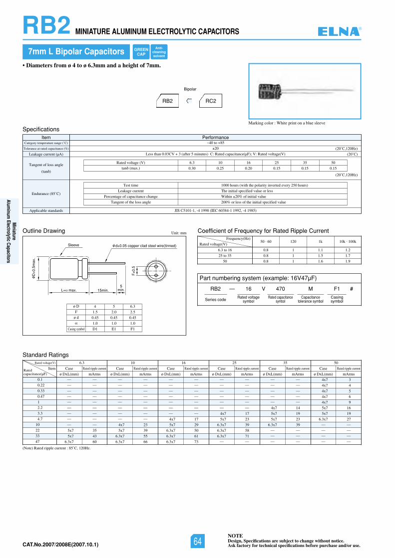
NOTEDesign, Specifications are subject to change without notice.Ask factory for technical specifications before purchase and/or use.CAT.No.2006/2007E(2006.10.1)
Part numbering system (example: 16V47µF)
RB2 — V
Series code
16 470 M
Rated voltagesymbol
Rated capacitancesymbol
Capacitancetolerance symbol
F1
Casingsymbol
#
Marking color : White print on a blue sleeve
7mm L Bipolar Capacitors
• Diameters from ø 4 to ø 6.3mm and a height of 7mm.
RB2 RC2
Bipolar
Outline Drawing
Standard Ratings
Coefficient of Frequency for Rated Ripple CurrentUnit: mm
Rated voltage(V)
Frequency(Hz)
6.3 to 16
25 to 35
50
50 . 60 120 1k 10k . 100k
0.8 1 1.1 1.2
0.8 1 1.5 1.7
0.8 1 1.6 1.9
L max. 15min.
Sleeve
D0.
5max
.
F0.
5
d 0.05 copper clad steel wire(tinned)
5min.
SpecificationsItem Performance
Category temperature range (˚C)
Tolerance at rated capacitance (%)
Leakage current (µA)
Tangent of loss angle
(tan )
Endurance (85˚C)
Applicable standards JIS C5101-1, -4 1998 (IEC 60384-1 1992, -4 1985)
40 to 85
20
Less than 0.03CV 3 (after 5 minutes) C: Rated capacitance(µF); V: Rated voltage(V)
05535261013.6)V(egatlovdetaR
0.30 0.25 0.20 0.15 0.15 0.15tan (max.)
(20˚C)
(20˚C,120Hz)
(20˚C,120Hz)
Test time
Leakage current
Percentage of capacitance change
Tangent of the loss angle
1000 hours (with the polarity inverted every 250 hours)
The initial specified value or less
Within 20% of initial value
200% or less of the initial specified value
(Note) Rated ripple current : 85˚C, 120Hz.
0.1
0.22
0.33
0.47
1
2.2
3.3
4.7
10
22
33
47
Rated voltage(V) 05535261013.6
ItemRatedcapacitance(µF)
— —
— —
— —
— —
— —
— —
— —
— —
— —
5x7 35
5x7 43
6.3x7 60
Case
ø DxL(mm) mArms
Rated ripple current
— —
— —
— —
— —
— —
— —
— —
— —
4x7 23
5x7 39
6.3x7 55
6.3x7 66
Case
ø DxL(mm) mArms
Rated ripple current
— —
— —
— —
— —
— —
— —
— —
4x7 17
5x7 29
6.3x7 50
6.3x7 61
6.3x7 73
Case
ø DxL(mm) mArms
Rated ripple current
— —
— —
— —
— —
— —
— —
4x7 17
5x7 23
6.3x7 39
6.3x7 58
6.3x7 71— —
Case
ø DxL(mm) mArms
Rated ripple current
— —
— —
— —
— —
— —
4x7 14
5x7 19
5x7 23
6.3x7 39— —
— —
— —
Case
ø DxL(mm) mArms
Rated ripple current
4x7 3
4x7 4
4x7 5
4x7 6
4x7 9
5x7 16
5x7 19
6.3x7 27— —
— —
— —
— —
Case
ø DxL(mm) mArms
Rated ripple current
RB2 MINIATURE ALUMINUM ELECTROLYTIC CAPACITORS
ø D
F
ø d
4 5 6.3
1.5 2.0 2.5
0.45 0.45 0.45
1.0 1.0 1.0
D1 E1 F1Casing symbol
GREENCAP
Anti-cleaningsolvent
®
Miniature
Aluminum
Electrolytic Capacitors
NOTEDesign, Specifications are subject to change without notice.Ask factory for technical specifications before purchase and/or use.64CAT.No.2007/2008E(2007.10.1)
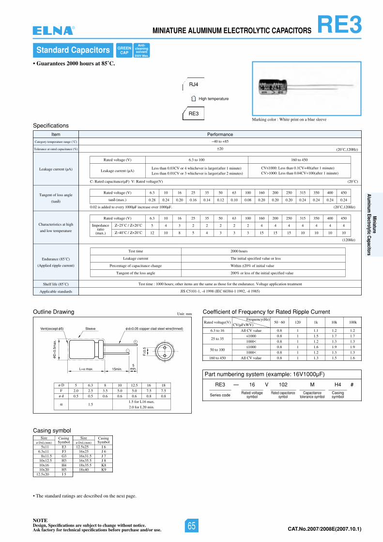
NOTEDesign, Specifications are subject to change without notice.Ask factory for technical specifications before purchase and/or use. CAT.No.2006/2007E(2006.10.1)
RE3MINIATURE ALUMINUM ELECTROLYTIC CAPACITORS
Coefficient of Frequency for Rated Ripple Current
Rated voltage(V)Frequency(Hz)
CV(µFxWV)
6.3 to 16
25 to 35
50 to 100
160 to 450
All CV value
1000
1000
1000
1000
All CV value
50 . 60 120 1k 10k 100k
0.8 1 1.1 1.2 1.2
0.8 1 1.5 1.7 1.7
0.8 1 1.2 1.3 1.3
0.8 1 1.6 1.9 1.9
0.8 1 1.2 1.3 1.3
0.8 1 1.3 1.5 1.6
Standard Capacitors
Marking color : White print on a blue sleeve
• Guarantees 2000 hours at 85˚C.
Specifications
Outline Drawing
Item Performance
Category temperature range (˚C)
Tolerance at rated capacitance (%)
Leakage current (µA)
Tangent of loss angle
(tan )
Characteristics at high
and low temperature
Endurance (85˚C)
(Applied ripple current)
Shelf life (85˚C) Test time : 1000 hours; other items are the same as those for the endurance. Voltage application treatment
Applicable standards JIS C5101-1, -4 1998 (IEC 60384-1 1992, -4 1985)
40 to 85
20
C: Rated capacitance(µF) V: Rated voltage(V)
0.02 is added to every 1000µF increase over 1000µF.
Rated voltage (V) 6.3 10 16 25 35 50 63 100 160 200 250 315 350 400 450
0.28 0.24 0.20 0.16 0.14 0.12 0.10 0.08 0.20 0.20 0.20 0.24 0.24 0.24 0.24
6.3 10 16 25 35 50 63 100 160 200 250 315 350 400 450
5 4 3 2 2 2 2 2 4 4 4 4 4 4 4
12 10 8 5 4 3 3 3 15 15 15 10 10 10 10
tan (max.)
(20˚C)
(20˚C,120Hz)
(20˚C,120Hz)
(120Hz)
054ot061001ot3.6)V(egatlovdetaR
Less than 0.03CV or 4 whichever is larger(after 1 minute)Less than 0.01CV or 3 whichever is larger(after 2 minutes)
CV 1000: Less than 0.1CV 40(after 1 minute)CV 1000: Less than 0.04CV 100(after 1 minute)
Leakage current (µA)
Test time
Leakage current
Percentage of capacitance change
Tangent of the loss angle
2000 hours
The initial specified value or less
Within 20% of initial value
200% or less of the initial specified value
Rated voltage (V)
Impedanceratio
(max.)
25˚C / 20˚C
40˚C / 20˚C
Unit: mm
L max. 15min.
SleeveVent(except 5)
D0.
5max
.
F0.
5
d 0.05 copper clad steel wire(tinned)
5min.
ø D
F
ø d
5 6.3 8 10 12.5 16 18
2.0 2.5 3.5 5.0 5.0 7.5 7.5
0.5 0.5 0.6 0.6 0.6 0.8 0.8
1.51.5 for L16 max.
2.0 for L20 min.
RJ4
RE3
High temperature
• The standard ratings are described on the next page.
Casing symbolSize
ø DxL(mm)CasingSymbol
Sizeø DxL(mm)
CasingSymbol
5x11 E36.3x11 F3
8x11.5 G310x12.5 H310x16 H410x20 H5
12.5x20 I 5
12.5x25 I 616x25 J 616x31.5 J 716x35.5 J 818x35.5 K818x40 K9
Part numbering system (example: 16V1000µF)
RE3 — V
Series code
16 102 M
Rated voltagesymbol
Rated capacitancesymbol
Capacitancetolerance symbol
H4
Casingsymbol
#
GREENCAP
Anti-cleaningsolvent
250V Max.
®
Miniature
Aluminum
Electrolytic Capacitors
NOTEDesign, Specifications are subject to change without notice.Ask factory for technical specifications before purchase and/or use. 65 CAT.No.2007/2008E(2007.10.1)
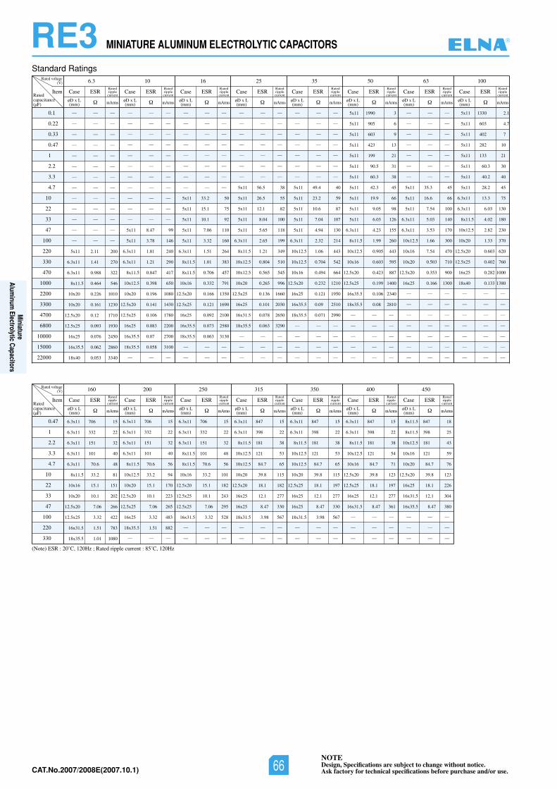
NOTEDesign, Specifications are subject to change without notice.Ask factory for technical specifications before purchase and/or use.CAT.No.2006/2007E(2006.10.1)
RE3 MINIATURE ALUMINUM ELECTROLYTIC CAPACITORS
(Note) ESR : 20˚C, 120Hz ; Rated ripple current : 85˚C, 120Hz
Standard Ratings
0.1
0.22
0.33
0.47
1
2.2
3.3
4.7
10
22
33
47
100
220
330
470
1000
2200
3300
4700
6800
10000
15000
22000
Rated voltage(V) 10 16 25 35 50 636.3 100
Item
— — —
— — —
— — —
— — —
— — —
— — —
— — —
— — —
— — —
— — —
— — —
— — —
— — —
5x11 2.11 200
6.3x11 1.41 270
6.3x11 0.988 322
8x11.5 0.464 546
10x20 0.226 1010
10x20 0.161 1230
12.5x20 0.12 1710
12.5x25 0.093 1930
16x25 0.076 2450
16x35.5 0.062 2860
18x40 0.053 3340
— — —
— — —
— — —
— — —
— — —
— — —
— — —
— — —
— — —
— — —
— — —
5x11 8.47 99
5x11 3.78 146
6.3x11 1.81 240
6.3x11 1.21 290
8x11.5 0.847 417
10x12.5 0.398 650
10x20 0.196 1080
12.5x20 0.141 1430
12.5x25 0.106 1780
16x25 0.083 2200
16x35.5 0.07 2700
18x35.5 0.058 3100
— — —
— — —
— — —
— — —
— — —
— — —
— — —
— — —
— — —
5x11 33.2 50
5x11 15.1 75
5x11 10.1 92
5x11 7.06 110
5x11 3.32 160
6.3x11 1.51 264
8x11.5 1.01 383
8x11.5 0.706 457
10x16 0.332 791
12.5x20 0.166 1350
12.5x25 0.121 1690
16x25 0.092 2100
16x35.5 0.073 2580
18x35.5 0.063 3130
— — —
— — —
— — —
— — —
— — —
— — —
— — —
— — —
— — —
5x11 56.5 38
5x11 26.5 55
5x11 12.1 82
5x11 8.04 100
5x11 5.65 118
6.3x11 2.65 199
8x11.5 1.21 349
10x12.5 0.804 510
10x12.5 0.565 545
10x20 0.265 996
12.5x25 0.136 1660
16x25 0.101 2030
16x31.5 0.078 2650
18x35.5 0.063 3290
— — —
— — —
— — —
— — —
— — —
— — —
— — —
— — —
— — —
— — —
5x11 49.4 40
5x11 23.2 59
5x11 10.6 87
5x11 7.04 107
5x11 4.94 130
6.3x11 2.32 214
10x12.5 1.06 443
10x12.5 0.704 542
10x16 0.494 664
12.5x20 0.232 1210
16x25 0.121 1950
16x35.5 0.09 2510
18x35.5 0.071 2990
— — —
— — —
— — —
— — —
5x11 1990 3
5x11 905 6
5x11 603 9
5x11 423 13
5x11 199 21
5x11 90.5 31
5x11 60.3 38
5x11 42.3 45
5x11 19.9 66
5x11 9.05 98
5x11 6.03 126
6.3x11 4.23 155
8x11.5 1.99 260
10x12.5 0.905 443
10x16 0.603 595
12.5x20 0.423 887
12.5x25 0.199 1400
16x35.5 0.106 2340
18x35.5 0.08 2810
— — —
— — —
— — —
— — —
— — —
— — —
— — —
— — —
— — —
— — —
— — —
— — —
5x11 35.3 45
5x11 16.6 66
5x11 7.54 100
6.3x11 5.03 140
6.3x11 3.53 170
10x12.5 1.66 300
10x16 7.54 470
10x20 0.503 710
12.5x20 0.353 900
16x25 0.166 1300
— — —
— — —
— — —
— — —
— — —
— — —
— — —
5x11 1330 2.1
5x11 603 4.7
5x11 402 7
5x11 282 10
5x11 133 21
5x11 60.3 30
5x11 40.2 40
5x11 28.2 45
6.3x11 13.3 75
6.3x11 6.03 130
8x11.5 4.02 180
10x12.5 2.82 230
10x20 1.33 370
12.5x20 0.603 620
12.5x25 0.402 760
16x25 0.282 1000
18x40 0.133 1380
— — —
— — —
— — —
— — —
— — —
— — —
— — —
Ratedcapacitance(µF)
øD x L(mm)
øD x L(mm)
øD x L(mm)
øD x L(mm)
øD x L(mm)
øD x L(mm)
øD x L(mm)
Case ESR
mArms
Ratedripplecurrent
Case ESR
mArms
Ratedripplecurrent
Case ESR
mArms
Ratedripplecurrent
Case ESR
mArms
Ratedripplecurrent
Case ESR
mArms
Ratedripplecurrent
Case ESR
mArms
Ratedripplecurrent
Case ESR
mArms
Ratedripplecurrent
Case ESR
mArms
Ratedripplecurrent
øD x L(mm)
0.47
1
2.2
3.3
4.7
10
22
33
47
100
220
330
Rated voltage(V) 200 250 315 350 400 450160
Item
6.3x11 706 15
6.3x11 332 22
6.3x11 151 32
6.3x11 101 40
6.3x11 70.6 48
8x11.5 33.2 81
10x16 15.1 151
10x20 10.1 202
12.5x20 7.06 266
12.5x25 3.32 422
16x31.5 1.51 783
18x35.5 1.01 1080
6.3x11 706 15
6.3x11 332 22
6.3x11 151 32
6.3x11 101 40
8x11.5 70.6 56
10x12.5 33.2 94
10x20 15.1 170
12.5x20 10.1 223
12.5x25 7.06 265
16x25 3.32 483
18x35.5 1.51 882
— — —
6.3x11 706 15
6.3x11 332 22
6.3x11 151 32
8x11.5 101 48
8x11.5 70.6 56
10x16 33.2 101
12.5x20 15.1 182
12.5x25 10.1 243
12.5x25 7.06 295
16x31.5 3.32 528
— — —
— — —
6.3x11 847 15
6.3x11 398 22
8x11.5 181 38
10x12.5 121 53
10x12.5 84.7 65
10x20 39.8 115
12.5x20 18.1 182
16x25 12.1 277
16x25 8.47 330
18x31.5 3.98 567
— — —
— — —
6.3x11 847 15
6.3x11 398 22
8x11.5 181 38
10x12.5 121 53
10x12.5 84.7 65
10x20 39.8 115
12.5x25 18.1 197
16x25 12.1 277
16x25 8.47 330
18x31.5 3.98 567
— — —
— — —
6.3x11 847 15
6.3x11 398 22
8x11.5 181 38
10x12.5 121 54
10x16 84.7 71
12.5x20 39.8 123
12.5x25 18.1 197
16x25 12.1 277
16x31.5 8.47 361
— — —
— — —
— — —
8x11.5 847 18
8x11.5 398 25
10x12.5 181 43
10x16 121 59
10x20 84.7 76
12.5x20 39.8 123
16x25 18.1 226
16x31.5 12.1 304
16x35.5 8.47 380
— — —
— — —
— — —
Ratedcapacitance(µF)
øD x L(mm)
øD x L(mm)
øD x L(mm)
øD x L(mm)
øD x L(mm)
øD x L(mm)
øD x L(mm)
Case ESR
mArms
Ratedripplecurrent
Case ESR
mArms
Ratedripplecurrent
Case ESR
mArms
Ratedripplecurrent
Case ESR
mArms
Ratedripplecurrent
Case ESR
mArms
Ratedripplecurrent
Case ESR
mArms
Ratedripplecurrent
Case ESR
mArms
Ratedripplecurrent
®
Miniature
Aluminum
Electrolytic Capacitors
NOTEDesign, Specifications are subject to change without notice.Ask factory for technical specifications before purchase and/or use.66CAT.No.2007/2008E(2007.10.1)
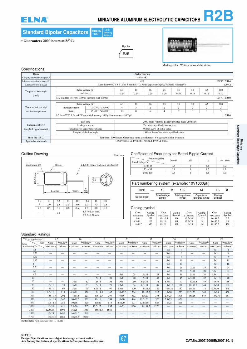
NOTEDesign, Specifications are subject to change without notice.Ask factory for technical specifications before purchase and/or use. CAT.No.2006/2007E(2006.10.1)
R2BMINIATURE ALUMINUM ELECTROLYTIC CAPACITORS
Outline Drawing
Standard Ratings
Coefficient of Frequency for Rated Ripple CurrentUnit: mm
Rated voltage(V)
Frequency(Hz)
6.3 to 16
25 to 35
50 to 100
(Note) Rated ripple current : 85˚C, 120Hz
50 . 60 120 1k 10k . 100k
0.8 1 1.1 1.2
0.8 1 1.5 1.7
0.8 1 1.6 1.9
0.1
0.22
0.33
0.47
1
2.2
3.3
4.7
10
22
33
47
100
220
330
470
1000
2200
3300
4700
Rated voltage(V) 6.3 10 16 25 35 50 63 100
ItemRatedcapacitance(µF)
— —
— —
— —
— —
— —
— —
— —
— —
— —
— —
5x11 58
5x11 69
6.3x11 115
8x11.5 202
8x11.5 247
10x12.5 350
10x20 611
12.5x25 1090
16x25 1490
16x31.5 1880
Case
ø DxL(mm) mArms
Rated ripplecurrent
— —
— —
— —
— —
— —
— —
— —
— —
— —
5x11 52
5x11 63
5x11 75
6.3x11 126
8x11.5 221
10x12.5 322
10x16 420
12.5x20 767
16x25 1380
16x31.5 1760
18x35.5 2280
Case
ø DxL(mm) mArms
Rated ripplecurrent
— —
— —
— —
— —
— —
— —
— —
— —
5x11 39
5x11 58
5x11 71
6.3x11 97
8x11.5 167
10x12.5 294
10x16 394
10x20 513
12.5x25 935
16x31.5 1660— —
— —
Case
ø DxL(mm) mArms
Rated ripplecurrent
— —
— —
— —
— —
— —
— —
— —
5x11 28
5x11 40
5x11 60
6.3x11 84
6.3x11 100
10x12.5 204
10x16 332
10x20 444
12.5x20 607
16x25 1120— —
— —
— —
Case
ø DxL(mm) mArms
Rated ripplecurrent
— —
— —
— —
— —
— —
— —
— —
5x11 28
5x11 42
6.3x11 71
6.3x11 87
8x11.5 122
10x12.5 212
10x20 375
12.5x20 526
12.5x25 685
16x31.5 1270— —
— —
— —
Case
ø DxL(mm) mArms
Rated ripplecurrent
5x11 4
5x11 7
5x11 8
5x11 10
5x11 14
5x11 21
5x11 26
5x11 31
5x11 45
6.3x11 77
8x11.5 111
10x12.5 157
10x20 273
12.5x25 506
12.5x25 620
16x25 861— —
— —
— —
— —
Case
ø DxL(mm) mArms
Rated ripplecurrent
— —
— —
— —
— —
— —
5x11 23
5x11 28
5x11 34
6.3x11 57
8x11.5 89
10x12.5 144
10x16 18
12.5x20 343
16x25 645— —
— —
— —
— —
— —
— —
Case
ø DxL(mm) mArms
Rated ripplecurrent
5x11 5
5x11 8
5x11 9
5x11 11
5x11 16
5x11 24
6.3x11 34
6.3x11 41
8x11.5 70
10x16 136
10x20 181
12.5x20 248
16x25 458
18x35.5 837— —
— —
— —
— —
— —
— —
Case
ø DxL(mm) mArms
Rated ripplecurrent
Standard Bipolar Capacitors
Marking color : White print on a blue sleeve
• Guarantees 2000 hours at 85˚C.
R2B
Bipolar
SpecificationsItem Performance
Category temperature range (˚C)
Tolerance at rated capacitance (%)
Leakage current (µA)
Tangent of loss angle
(tan )
Characteristics at high
and low temperature
Endurance (85˚C)
(Applied ripple current)
Shelf life (85˚ tnemtaertnoitacilppaegatloV.ecnarudnesaemasevahrehtO.sruoh0001:emittseT)C
Applicable standards JIS C5101-1, -4 1998 (IEC 60384-1 1992, -4 1985)
40 to 85
20
Less than 0.03CV 3 (after 5 minutes) C: Rated capacitance(µF); V: Rated voltage(V) (20˚C)
(20˚C,120Hz)
(20˚C,120Hz)
(120Hz)
Test time
Leakage current
Percentage of capacitance change
Tangent of the loss angle
2000 hours (with the polarity inverted every 250 hours)
The initial specified value or less
Within 20% of initial value
150% or less of the initial specified value
0013605535261013.6)V(egatlovdetaR
0.24 0.24 0.20 0.20 0.16 0.14 0.12 0.10tan (max.)
0013605535261013.6)V(egatlovdetaR
4 3 2 2 2 2 2 2
10 8 6 4 3 3 3 3
Impedance ratio(max.)
25˚C / 20˚C
40˚C / 20˚C
L max. 15min.5
min.
SleeveVent(except 5)
D0.
5max
.
F0.
5
d 0.05 copper clad steel wire(tinned)
ø D
F
ø d
5 6.3 8 10 12.5 16 18
2.0 2.5 3.5 5.0 5.0 7.5 7.5
0.5 0.5 0.6 0.6 0.6 0.8 0.8
1.51.5 for L16 max.
2.0 for L20 min.
0.02 is added to every 1000µF increase over 1000µF
0.5 for 25˚C, 1 for 40˚C are added to every 1000µF increase over 1000µF
Casing symbolCase
ø DxL(mm)CasingSymbol
Caseø DxL(mm)
CasingSymbol
Caseø DxL(mm)
CasingSymbol
Caseø DxL(mm)
CasingSymbol
5x11 E36.3x11 F3
8x11.5 G3
10x12.5 H310x16 H410x20 H5
16x31.5 J 716x35.5 J 818x35.5 K8
12.5x20 I 512.5x25 I 6
16x25 J 6
Part numbering system (example: 10V1000µF)
R2B — V
Series code
10 102 M
Rated voltagesymbol
Rated capacitancesymbol
Capacitancetolerance symbol
I 5
Casingsymbol
#
GREENCAP
Anti-cleaningsolvent
®
Miniature
Aluminum
Electrolytic Capacitors
NOTEDesign, Specifications are subject to change without notice.Ask factory for technical specifications before purchase and/or use. 67 CAT.No.2007/2008E(2007.10.1)
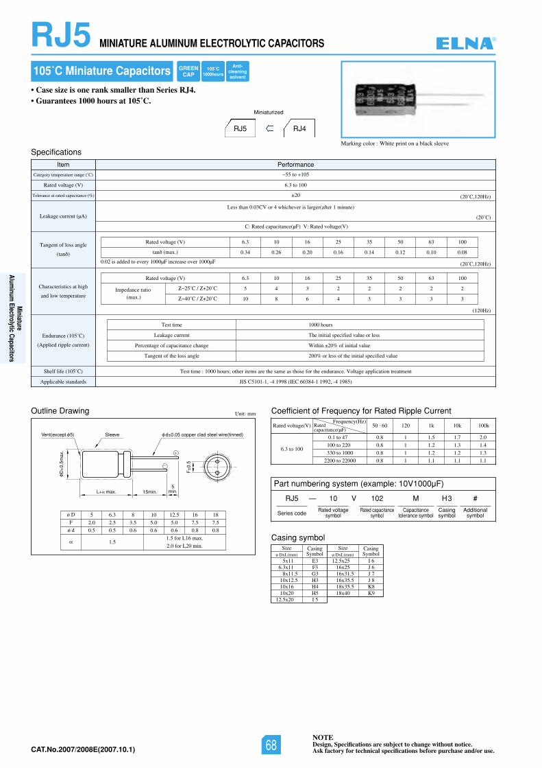
NOTEDesign, Specifications are subject to change without notice.Ask factory for technical specifications before purchase and/or use.CAT.No.2006/2007E(2006.10.1)
JIS C5101-1, -4 1998 (IEC 60384-1 1992, -4 1985)
(120Hz)
Test time
Leakage current
Percentage of capacitance change
Tangent of the loss angle
1000 hours
The initial specified value or less
Within 20% of initial value
200% or less of the initial specified value
0.02 is added to every 1000µF increase over 1000µF
Outline Drawing Unit: mm
L max. 15min.
SleeveVent(except 5)
D0.
5max
.
F0.
5
d 0.05 copper clad steel wire(tinned)
5min.
ø D
F
ø d
5 6.3 8 10 12.5 16 18
2.0 2.5 3.5 5.0 5.0 7.5 7.5
0.5 0.5 0.6 0.6 0.6 0.8 0.8
1.51.5 for L16 max.
2.0 for L20 min.
105˚C Miniature Capacitors
• Case size is one rank smaller than Series RJ4.• Guarantees 1000 hours at 105˚C.
Specifications
Item Performance
Rated voltage (V)
Category temperature range (˚C)
Tolerance at rated capacitance (%)
Leakage current (µA)
Tangent of loss angle
(tan )
Characteristics at high
and low temperature
Endurance (105˚C)
(Applied ripple current)
Shelf life (105˚C)
Applicable standards
Test time : 1000 hours; other items are the same as those for the endurance. Voltage application treatment
6.3 to 100
55 to 105
20
C: Rated capacitance(µF) V: Rated voltage(V)
RJ5 RJ4
Miniaturized
Marking color : White print on a black sleeve
Less than 0.03CV or 4 whichever is larger(after 1 minute)
(20˚C)
(20˚C,120Hz)
(20˚C,120Hz)
Coefficient of Frequency for Rated Ripple Current
Rated voltage(V)Frequency(Hz)
6.3 to 100
0.1 to 47
100 to 220
330 to 1000
2200 to 22000
50 . 60 120 1k 10k 100k
0.8 1 1.5 1.7 2.0
0.8 1 1.2 1.3 1.4
0.8 1 1.2 1.2 1.3
0.8 1 1.1 1.1 1.1
Ratedcapacitance(µF)
RJ5 MINIATURE ALUMINUM ELECTROLYTIC CAPACITORS
0013605535261013.6)V(egatlovdetaR
0.34 0.26 0.20 0.16 0.14 0.12 0.10 0.08tan (max.)
0013605535261013.6)V(egatlovdetaR
5 4 3 2 2 2 2 2
10 8 6 4 3 3 3 3
Impedance ratio(max.)
25˚C / 20˚C
40˚C / 20˚C
Casing symbolSize
ø DxL(mm)CasingSymbol
Sizeø DxL(mm)
CasingSymbol
5x11 E36.3x11 F3
8x11.5 G310x12.5 H310x16 H410x20 H5
12.5x20 I 5
12.5x25 I 616x25 J 616x31.5 J 716x35.5 J 818x35.5 K818x40 K9
Part numbering system (example: 10V1000µF)
RJ5 — V
Series code
10 102 M
Rated voltagesymbol
Rated capacitancesymbol
Capacitancetolerance symbol
H3 #
Casingsymbol
Additionalsymbol
105˚C1000hours
GREENCAP
Anti-cleaningsolvent
®
Miniature
Aluminum
Electrolytic Capacitors
NOTEDesign, Specifications are subject to change without notice.Ask factory for technical specifications before purchase and/or use.68CAT.No.2007/2008E(2007.10.1)
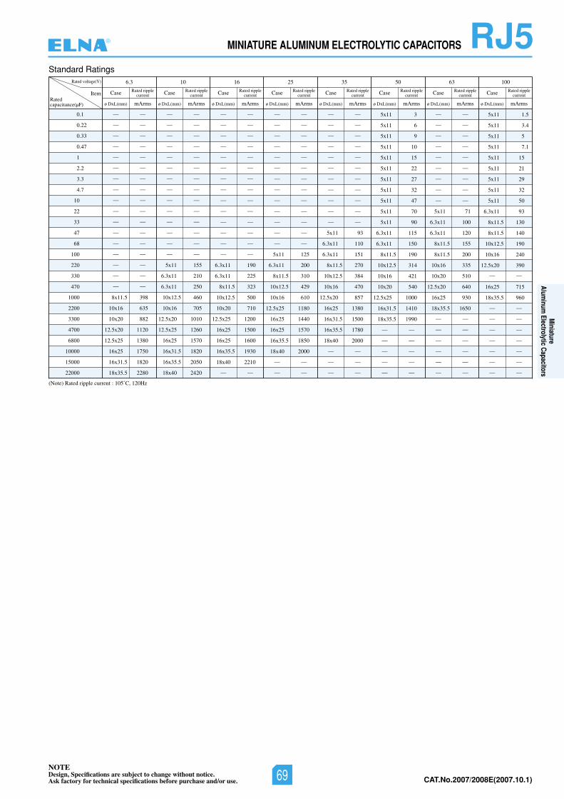
NOTEDesign, Specifications are subject to change without notice.Ask factory for technical specifications before purchase and/or use. CAT.No.2006/2007E(2006.10.1)
RJ5MINIATURE ALUMINUM ELECTROLYTIC CAPACITORS
Standard Ratings
(Note) Rated ripple current : 105˚C, 120Hz
0.1
0.22
0.33
0.47
1
2.2
3.3
4.7
10
22
33
47
68
100
220
330
470
1000
2200
3300
4700
6800
10000
15000
22000
Rated voltage(V) 6.3 10 16 25 35 50 63 100
ItemRatedcapacitance(µF)
— —
— —
— —
— —
— —
— —
— —
— —
— —
— —
— —
— —
— —
— —
— —
— —
— —
8x11.5 398
10x16 635
10x20 882
12.5x20 1120
12.5x25 1380
16x25 1750
16x31.5 1820
18x35.5 2280
Case
ø DxL(mm) mArms
Rated ripplecurrent
— —
— —
— —
— —
— —
— —
— —
— —
— —
— —
— —
— —
— —
— —
5x11 155
6.3x11 210
6.3x11 250
10x12.5 460
10x16 705
12.5x20 1010
12.5x25 1260
16x25 1570
16x31.5 1820
16x35.5 2050
18x40 2420
— —
— —
— —
— —
— —
— —
— —
— —
— —
— —
— —
— —
— —
— —
6.3x11 190
6.3x11 225
8x11.5 323
10x12.5 500
10x20 710
12.5x25 1200
16x25 1500
16x25 1600
16x35.5 1930
18x40 2210
— —
— —
— —
— —
— —
— —
— —
— —
— —
— —
— —
— —
— —
— —
5x11 125
6.3x11 200
8x11.5 310
10x12.5 429
10x16 610
12.5x25 1180
16x25 1440
16x25 1570
16x35.5 1850
18x40 2000
— —
— —
— —
— —
— —
— —
— —
— —
— —
— —
— —
— —
— —
5x11 93
6.3x11 110
6.3x11 151
8x11.5 270
10x12.5 384
10x16 470
12.5x20 857
16x25 1380
16x31.5 1500
16x35.5 1780
18x40 2000
— —
— —
— —
— —
— —
— —
— —
— —
— —
— —
— —
— —
5x11 71
6.3x11 100
6.3x11 120
8x11.5 155
8x11.5 200
10x16 335
10x20 510
12.5x20 640
16x25 930
18x35.5 1650
— —
— —
— —
— —
— —
— —
5x11 3
5x11 6
5x11 9
5x11 10
5x11 15
5x11 22
5x11 27
5x11 32
5x11 47
5x11 70
5x11 90
6.3x11 115
6.3x11 150
8x11.5 190
10x12.5 314
10x16 421
10x20 540
12.5x25 1000
16x31.5 1410
18x35.5 1990
— —
— —
— —
— —
— —
5x11 1.5
5x11 3.4
5x11 5
5x11 7.1
5x11 15
5x11 21
5x11 29
5x11 32
5x11 50
6.3x11 93
8x11.5 130
8x11.5 140
10x12.5 190
10x16 240
12.5x20 390
— —
16x25 715
18x35.5 960
— —
— —
— —
— —
— —
— —
— —
Case
ø DxL(mm) mArms
Rated ripplecurrent Case
ø DxL(mm) mArms
Rated ripplecurrent Case
ø DxL(mm) mArms
Rated ripplecurrent Case
ø DxL(mm) mArms
Rated ripplecurrent Case
ø DxL(mm) mArms
Rated ripplecurrent Case
ø DxL(mm) mArms
Rated ripplecurrent Case
ø DxL(mm) mArms
Rated ripplecurrent
®
Miniature
Aluminum
Electrolytic Capacitors
NOTEDesign, Specifications are subject to change without notice.Ask factory for technical specifications before purchase and/or use. 69 CAT.No.2007/2008E(2007.10.1)
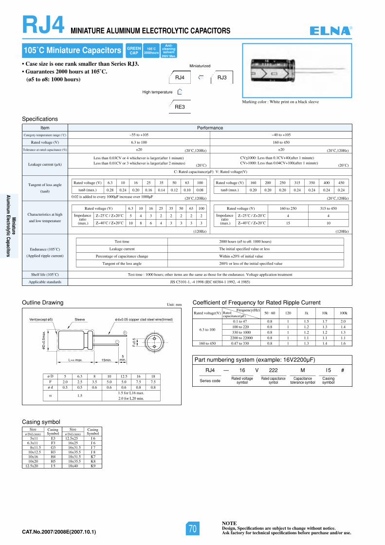
NOTEDesign, Specifications are subject to change without notice.Ask factory for technical specifications before purchase and/or use.CAT.No.2006/2007E(2006.10.1)
JIS C5101-1, -4 1998 (IEC 60384-1 1992, -4 1985)
(120Hz)(120Hz)
Test time
Leakage current
Percentage of capacitance change
Tangent of the loss angle
2000 hours (ø5 to ø8: 1000 hours)
The initial specified value or less
Within 20% of initial value
200% or less of the initial specified value
0.02 is added to every 1000µF increase over 1000µF
Outline Drawing Unit: mm
L max. 15min.
SleeveVent(except 5)
D0.
5max
.
F0.
5
d 0.05 copper clad steel wire(tinned)
5min.
ø D
F
ø d
5 6.3 8 10 12.5 16 18
2.0 2.5 3.5 5.0 5.0 7.5 7.5
0.5 0.5 0.6 0.6 0.6 0.8 0.8
1.51.5 for L16 max.
2.0 for L20 min.
105˚C Miniature Capacitors
• Case size is one rank smaller than Series RJ3.• Guarantees 2000 hours at 105˚C.
(ø5 to ø8: 1000 hours)
Specifications
Item Performance
Rated voltage (V)
Category temperature range (˚C)
Tolerance at rated capacitance (%)
Leakage current (µA)
Tangent of loss angle
(tan )
Characteristics at high
and low temperature
Endurance (105˚C)
(Applied ripple current)
Shelf life (105˚C)
Applicable standards
Test time : 1000 hours; other items are the same as those for the endurance. Voltage application treatment
6.3 to 100 160 to 450
55 to 105 40 to 105
20 20
C: Rated capacitance(µF) V: Rated voltage(V)
Rated voltage (V)
Rated voltage (V)
tan (max.)
6.3 10 16 25 35 50 63 100
0.28 0.24 0.20 0.16 0.14 0.12 0.10 0.08
Rated voltage (V)
tan (max.)
160 200 250 315 350 400 450
0.20 0.20 0.20 0.24 0.24 0.24 0.24
6.3 10 16 25 35 50 63 100
5 4 3 2 2 2 2 2
10 8 6 4 3 3 3 3
RJ4 RJ3
RE3
High temperature
Miniaturized
Marking color : White print on a black sleeve
Less than 0.03CV or 4 whichever is larger(after 1 minute)Less than 0.01CV or 3 whichever is larger(after 2 minutes)
CV 1000: Less than 0.1CV 40(after 1 minute)CV 1000: Less than 0.04CV 100(after 1 minute)
(20˚C)
(20˚C,120Hz)
(20˚C,120Hz)(20˚C,120Hz)
(20˚C)
(20˚C,120Hz)
Impedanceratio
(max.)
25˚C / 20˚C
40˚C / 20˚C
Rated voltage (V) 160 to 250 315 to 450
4 4
15 10
Impedanceratio
(max.)
25˚C / 20˚C
40˚C / 20˚C
Coefficient of Frequency for Rated Ripple Current
Rated voltage(V)Frequency(Hz)
6.3 to 100
160 to 450
0.1 to 47
100 to 220
330 to 1000
2200 to 22000
0.47 to 330
50 . 60 120 1k 10k 100k
0.8 1 1.5 1.7 2.0
0.8 1 1.2 1.3 1.4
0.8 1 1.2 1.2 1.3
0.8 1 1.1 1.1 1.1
0.8 1 1.3 1.4 1.6
Ratedcapacitance(µF)
RJ4 MINIATURE ALUMINUM ELECTROLYTIC CAPACITORS
Casing symbolSize
ø DxL(mm)CasingSymbol
Sizeø DxL(mm)
CasingSymbol
5x11 E36.3x11 F3
8x11.5 G310x12.5 H310x16 H410x20 H5
12.5x20 I 5
12.5x25 I 616x25 J 616x31.5 J 716x35.5 J 818x31.5 K718x35.5 K818x40 K9
Part numbering system (example: 16V2200µF)
RJ4 — V
Series code
16 222 M
Rated voltagesymbol
Rated capacitancesymbol
Capacitancetolerance symbol
I 5
Casingsymbol
#
105˚C2000hours
GREENCAP
Anti-cleaningsolvent
250V Max.
®
Miniature
Aluminum
Electrolytic Capacitors
NOTEDesign, Specifications are subject to change without notice.Ask factory for technical specifications before purchase and/or use.70CAT.No.2007/2008E(2007.10.1)
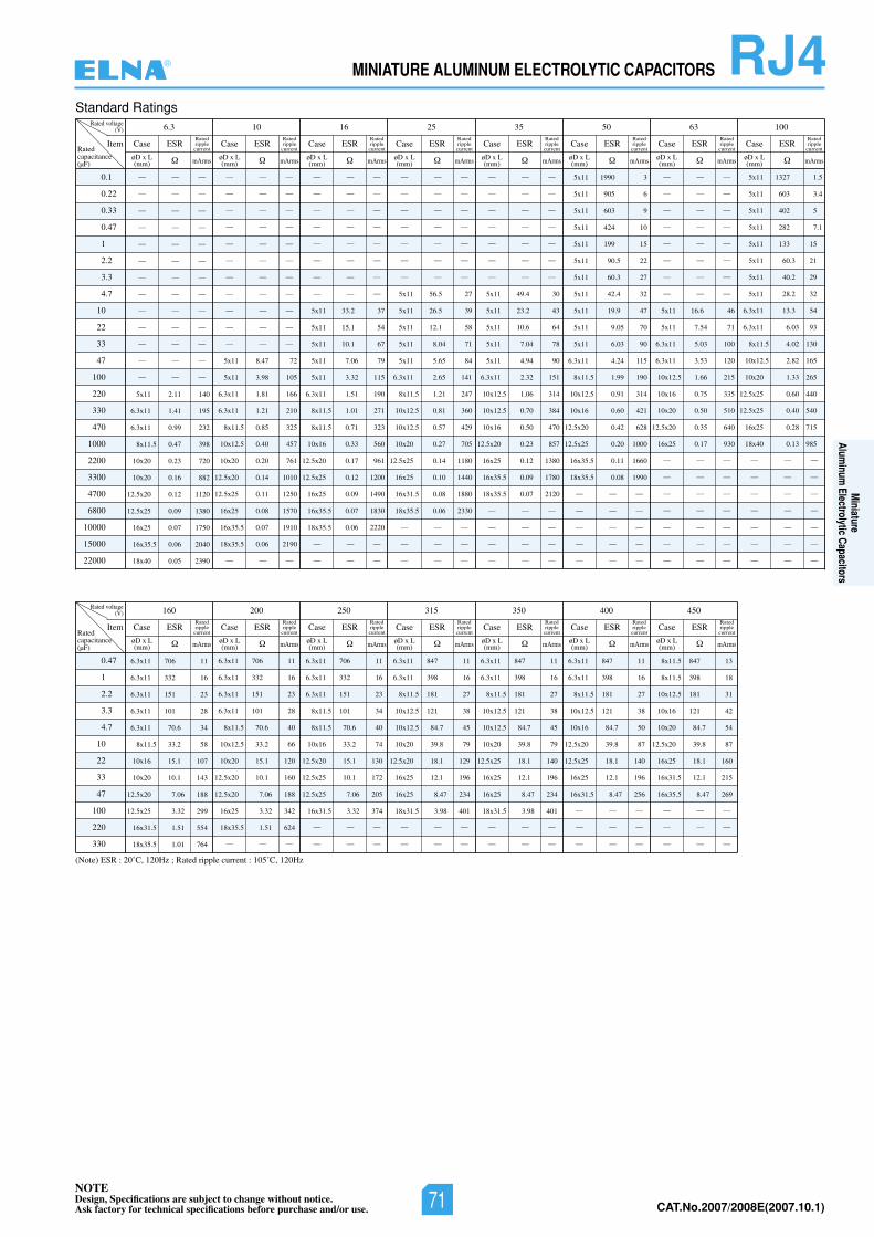
NOTEDesign, Specifications are subject to change without notice.Ask factory for technical specifications before purchase and/or use. CAT.No.2006/2007E(2006.10.1)
(Note) ESR : 20˚C, 120Hz ; Rated ripple current : 105˚C, 120Hz
Standard Ratings
0.1
0.22
0.33
0.47
1
2.2
3.3
4.7
10
22
33
47
100
220
330
470
1000
2200
3300
4700
6800
10000
15000
22000
Rated voltage(V) 10 16 25 35 50 636.3 100
Item
— — —
— — —
— — —
— — —
— — —
— — —
— — —
— — —
— — —
— — —
— — —
— — —
— — —
5x11 2.11 140
6.3x11 1.41 195
6.3x11 0.99 232
8x11.5 0.47 398
10x20 0.23 720
10x20 0.16 882
12.5x20 0.12 1120
12.5x25 0.09 1380
16x25 0.07 1750
16x35.5 0.06 2040
18x40 0.05 2390
— — —
— — —
— — —
— — —
— — —
— — —
— — —
— — —
— — —
— — —
— — —
5x11 8.47 72
5x11 3.98 105
6.3x11 1.81 166
6.3x11 1.21 210
8x11.5 0.85 325
10x12.5 0.40 457
10x20 0.20 761
12.5x20 0.14 1010
12.5x25 0.11 1250
16x25 0.08 1570
16x35.5 0.07 1910
18x35.5 0.06 2190
— — —
— — —
— — —
— — —
— — —
— — —
— — —
— — —
— — —
5x11 33.2 37
5x11 15.1 54
5x11 10.1 67
5x11 7.06 79
5x11 3.32 115
6.3x11 1.51 190
8x11.5 1.01 271
8x11.5 0.71 323
10x16 0.33 560
12.5x20 0.17 961
12.5x25 0.12 1200
16x25 0.09 1490
16x35.5 0.07 1830
18x35.5 0.06 2220
— — —
— — —
— — —
— — —
— — —
— — —
— — —
— — —
— — —
5x11 56.5 27
5x11 26.5 39
5x11 12.1 58
5x11 8.04 71
5x11 5.65 84
6.3x11 2.65 141
8x11.5 1.21 247
10x12.5 0.81 360
10x12.5 0.57 429
10x20 0.27 705
12.5x25 0.14 1180
16x25 0.10 1440
16x31.5 0.08 1880
18x35.5 0.06 2330
— — —
— — —
— — —
— — —
— — —
— — —
— — —
— — —
— — —
— — —
5x11 49.4 30
5x11 23.2 43
5x11 10.6 64
5x11 7.04 78
5x11 4.94 90
6.3x11 2.32 151
10x12.5 1.06 314
10x12.5 0.70 384
10x16 0.50 470
12.5x20 0.23 857
16x25 0.12 1380
16x35.5 0.09 1780
18x35.5 0.07 2120
— — —
— — —
— — —
— — —
5x11 1990 3
5x11 905 6
5x11 603 9
5x11 424 10
5x11 199 15
5x11 90.5 22
5x11 60.3 27
5x11 42.4 32
5x11 19.9 47
5x11 9.05 70
5x11 6.03 90
6.3x11 4.24 115
8x11.5 1.99 190
10x12.5 0.91 314
10x16 0.60 421
12.5x20 0.42 628
12.5x25 0.20 1000
16x35.5 0.11 1660
18x35.5 0.08 1990
— — —
— — —
— — —
— — —
— — —
— — —
— — —
— — —
— — —
— — —
— — —
— — —
— — —
5x11 16.6 46
5x11 7.54 71
6.3x11 5.03 100
6.3x11 3.53 120
10x12.5 1.66 215
10x16 0.75 335
10x20 0.50 510
12.5x20 0.35 640
16x25 0.17 930
— — —
— — —
— — —
— — —
— — —
— — —
— — —
5x11 1327 1.5
5x11 603 3.4
5x11 402 5
5x11 282 7.1
5x11 133 15
5x11 60.3 21
5x11 40.2 29
5x11 28.2 32
6.3x11 13.3 54
6.3x11 6.03 93
8x11.5 4.02 130
10x12.5 2.82 165
10x20 1.33 265
12.5x25 0.60 440
12.5x25 0.40 540
16x25 0.28 715
18x40 0.13 985
— — —
— — —
— — —
— — —
— — —
— — —
— — —
Ratedcapacitance(µF)
øD x L(mm)
øD x L(mm)
øD x L(mm)
øD x L(mm)
øD x L(mm)
øD x L(mm)
øD x L(mm)
Case ESR
mArms
Ratedripplecurrent
Case ESR
mArms
Ratedripplecurrent
Case ESR
mArms
Ratedripplecurrent
Case ESR
mArms
Ratedripplecurrent
Case ESR
mArms
Ratedripplecurrent
Case ESR
mArms
Ratedripplecurrent
Case ESR
mArms
Ratedripplecurrent
Case ESR
mArms
Ratedripplecurrent
øD x L(mm)
0.47
1
2.2
3.3
4.7
10
22
33
47
100
220
330
Rated voltage(V) 200 250 315 350 400 450160
Item
6.3x11 706 11
6.3x11 332 16
6.3x11 151 23
6.3x11 101 28
6.3x11 70.6 34
8x11.5 33.2 58
10x16 15.1 107
10x20 10.1 143
12.5x20 7.06 188
12.5x25 3.32 299
16x31.5 1.51 554
18x35.5 1.01 764
6.3x11 706 11
6.3x11 332 16
6.3x11 151 23
6.3x11 101 28
8x11.5 70.6 40
10x12.5 33.2 66
10x20 15.1 120
12.5x20 10.1 160
12.5x20 7.06 188
16x25 3.32 342
18x35.5 1.51 624
— — —
6.3x11 706 11
6.3x11 332 16
6.3x11 151 23
8x11.5 101 34
8x11.5 70.6 40
10x16 33.2 74
12.5x20 15.1 130
12.5x25 10.1 172
12.5x25 7.06 205
16x31.5 3.32 374
— — —
— — —
6.3x11 847 11
6.3x11 398 16
8x11.5 181 27
10x12.5 121 38
10x12.5 84.7 45
10x20 39.8 79
12.5x20 18.1 129
16x25 12.1 196
16x25 8.47 234
18x31.5 3.98 401
— — —
— — —
6.3x11 847 11
6.3x11 398 16
8x11.5 181 27
10x12.5 121 38
10x12.5 84.7 45
10x20 39.8 79
12.5x25 18.1 140
16x25 12.1 196
16x25 8.47 234
18x31.5 3.98 401
— — —
— — —
6.3x11 847 11
6.3x11 398 16
8x11.5 181 27
10x12.5 121 38
10x16 84.7 50
12.5x20 39.8 87
12.5x25 18.1 140
16x25 12.1 196
16x31.5 8.47 256
— — —
— — —
— — —
8x11.5 847 13
8x11.5 398 18
10x12.5 181 31
10x16 121 42
10x20 84.7 54
12.5x20 39.8 87
16x25 18.1 160
16x31.5 12.1 215
16x35.5 8.47 269
— — —
— — —
— — —
Ratedcapacitance(µF)
øD x L(mm)
øD x L(mm)
øD x L(mm)
øD x L(mm)
øD x L(mm)
øD x L(mm)
øD x L(mm)
Case ESR
mArms
Ratedripplecurrent
Case ESR
mArms
Ratedripplecurrent
Case ESR
mArms
Ratedripplecurrent
Case ESR
mArms
Ratedripplecurrent
Case ESR
mArms
Ratedripplecurrent
Case ESR
mArms
Ratedripplecurrent
Case ESR
mArms
Ratedripplecurrent
RJ4MINIATURE ALUMINUM ELECTROLYTIC CAPACITORS®
Miniature
Aluminum
Electrolytic Capacitors
NOTEDesign, Specifications are subject to change without notice.Ask factory for technical specifications before purchase and/or use. 71 CAT.No.2007/2008E(2007.10.1)
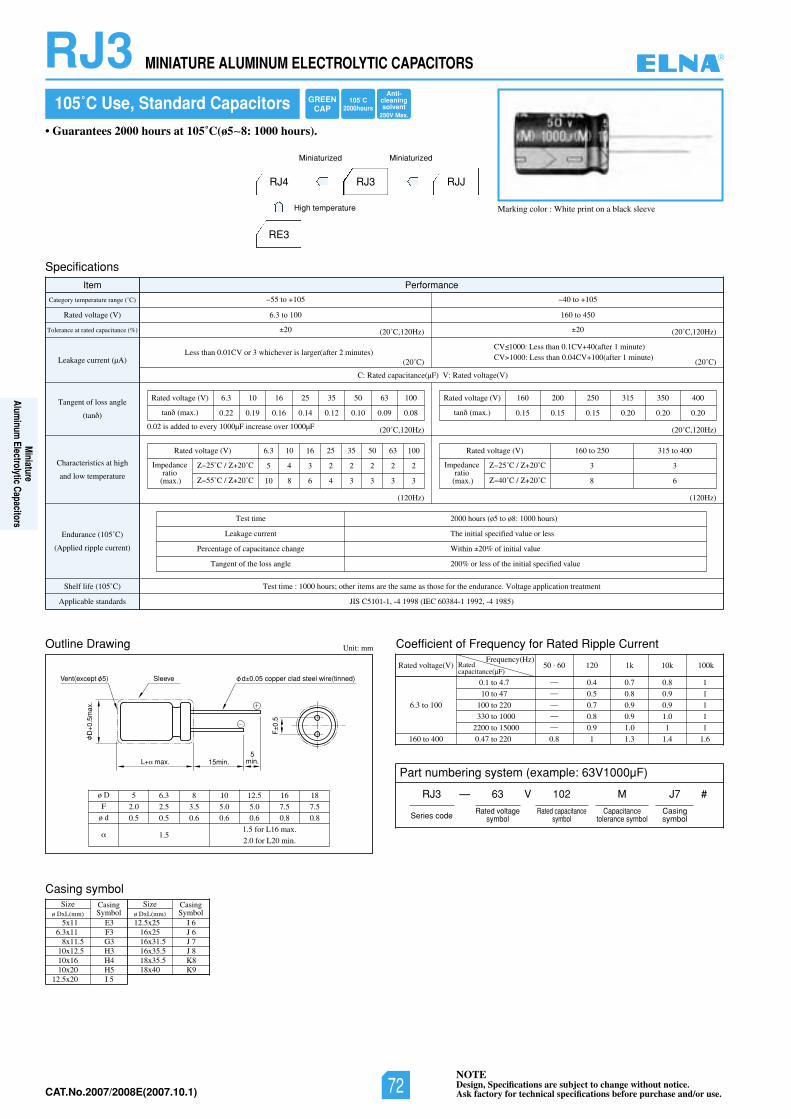
NOTEDesign, Specifications are subject to change without notice.Ask factory for technical specifications before purchase and/or use.CAT.No.2006/2007E(2006.10.1)
RJ3 MINIATURE ALUMINUM ELECTROLYTIC CAPACITORS
JIS C5101-1, -4 1998 (IEC 60384-1 1992, -4 1985)
(120Hz)(120Hz)
Test time
Leakage current
Percentage of capacitance change
Tangent of the loss angle
2000 hours (ø5 to ø8: 1000 hours)
The initial specified value or less
Within 20% of initial value
200% or less of the initial specified value
0.02 is added to every 1000µF increase over 1000µF
Outline Drawing Unit: mm
L max. 15min.
SleeveVent(except 5)
D0.
5max
.
F0.
5
d 0.05 copper clad steel wire(tinned)
5min.
ø D
F
ø d
5 6.3 8 10 12.5 16 18
2.0 2.5 3.5 5.0 5.0 7.5 7.5
0.5 0.5 0.6 0.6 0.6 0.8 0.8
1.51.5 for L16 max.
2.0 for L20 min.
105˚C Use, Standard Capacitors
Specifications
Item Performance
Rated voltage (V)
Category temperature range (˚C)
Tolerance at rated capacitance (%)
Leakage current (µA)
Tangent of loss angle
(tan )
Characteristics at high
and low temperature
Endurance (105˚C)
(Applied ripple current)
Shelf life (105˚C)
Applicable standards
Test time : 1000 hours; other items are the same as those for the endurance. Voltage application treatment
6.3 to 100 160 to 450
55 to 105 40 to 105
20 20
C: Rated capacitance(µF) V: Rated voltage(V)
Rated voltage (V)
Rated voltage (V)
tan (max.)
6.3 10 16 25 35 50 63 100
0.22 0.19 0.16 0.14 0.12 0.10 0.09 0.08
Rated voltage (V)
tan (max.)
160 200 250 315 350 400
0.15 0.15 0.15 0.20 0.20 0.20
6.3 10 16 25 35 50 63 100
5 4 3 2 2 2 2 2
10 8 6 4 3 3 3 3
Marking color : White print on a black sleeve
Less than 0.01CV or 3 whichever is larger(after 2 minutes) CV 1000: Less than 0.1CV 40(after 1 minute)CV 1000: Less than 0.04CV 100(after 1 minute)
(20˚C)
(20˚C,120Hz)
(20˚C,120Hz)(20˚C,120Hz)
(20˚C)
(20˚C,120Hz)
Impedanceratio
(max.)
25˚C / 20˚C
55˚C / 20˚C
Rated voltage (V) 160 to 250 315 to 400
3 3
8 6
Impedanceratio
(max.)
25˚C / 20˚C
40˚C / 20˚C
Coefficient of Frequency for Rated Ripple Current
Rated voltage(V)Frequency(Hz)
6.3 to 100
160 to 400
0.1 to 4.7
10 to 47
100 to 220
330 to 1000
2200 to 15000
0.47 to 220
50 . 60 120 1k 10k 100k
— 0.4 0.7 0.8 1— 0.5 0.8 0.9 1— 0.7 0.9 0.9 1— 0.8 0.9 1.0 1— 0.9 1.0 1 1
0.8 1 1.3 1.4 1.6
Ratedcapacitance(µF)
Casing symbolSize
ø DxL(mm)CasingSymbol
Sizeø DxL(mm)
CasingSymbol
5x11 E36.3x11 F3
8x11.5 G310x12.5 H310x16 H410x20 H5
12.5x20 I 5
12.5x25 I 616x25 J 616x31.5 J 716x35.5 J 818x35.5 K818x40 K9
Part numbering system (example: 63V1000µF)
RJ3 — V
Series code
63 102 M
Rated voltagesymbol
Rated capacitancesymbol
Capacitancetolerance symbol
J7
Casingsymbol
#
• Guarantees 2000 hours at 105˚C(ø5~8: 1000 hours).
RJ4 RJ3 RJJ
RE3
High temperature
Miniaturized Miniaturized
105˚C2000hours
GREENCAP
Anti-cleaningsolvent
250V Max.
®
Miniature
Aluminum
Electrolytic Capacitors
NOTEDesign, Specifications are subject to change without notice.Ask factory for technical specifications before purchase and/or use.72CAT.No.2007/2008E(2007.10.1)
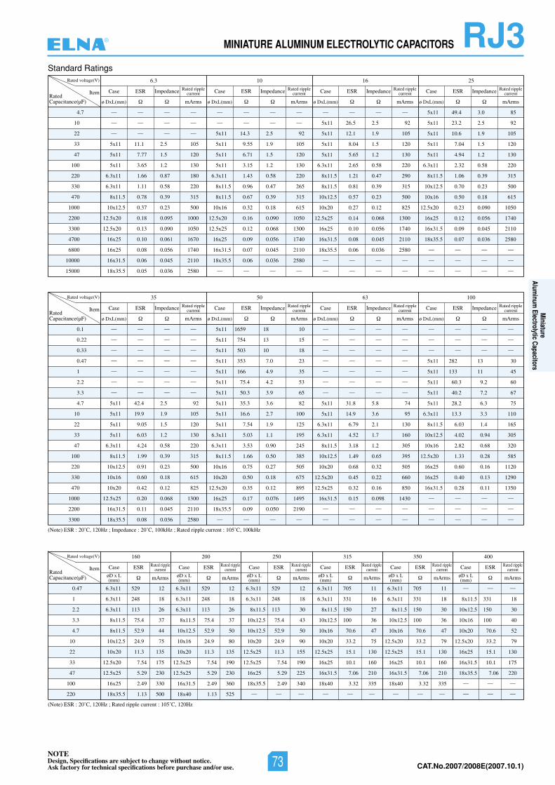
NOTEDesign, Specifications are subject to change without notice.Ask factory for technical specifications before purchase and/or use. CAT.No.2006/2007E(2006.10.1)
RJ3MINIATURE ALUMINUM ELECTROLYTIC CAPACITORS
(Note) ESR : 20˚C, 120Hz ; Rated ripple current : 105˚C, 120Hz
(Note) ESR : 20˚C, 120Hz ; Impedance : 20˚C, 100kHz ; Rated ripple current : 105˚C, 100kHz
RatedCapacitance(µF)
Standard Ratings
4.7
10
22
33
47
100
220
330
470
1000
2200
3300
4700
6800
10000
15000
Rated voltage(V) 5261013.6
Item
— — — —
— — — —
— — — —
5x11 11.1 2.5 105
5x11 7.77 1.5 120
5x11 3.65 1.2 130
6.3x11 1.66 0.87 180
6.3x11 1.11 0.58 220
8x11.5 0.78 0.39 315
10x12.5 0.37 0.23 500
12.5x20 0.18 0.095 1000
12.5x20 0.13 0.090 1050
16x25 0.10 0.061 1670
16x25 0.08 0.056 1740
16x31.5 0.06 0.045 2110
18x35.5 0.05 0.036 2580
— — — —
— — — —
5x11 14.3 2.5 92
5x11 9.55 1.9 105
5x11 6.71 1.5 120
5x11 3.15 1.2 130
6.3x11 1.43 0.58 220
8x11.5 0.96 0.47 265
8x11.5 0.67 0.39 315
10x16 0.32 0.18 615
12.5x20 0.16 0.090 1050
12.5x25 0.12 0.068 1300
16x25 0.09 0.056 1740
16x31.5 0.07 0.045 2110
18x35.5 0.06 0.036 2580
— — — —
— — — —
5x11 26.5 2.5 92
5x11 12.1 1.9 105
5x11 8.04 1.5 120
5x11 5.65 1.2 130
6.3x11 2.65 0.58 220
8x11.5 1.21 0.47 290
8x11.5 0.81 0.39 315
10x12.5 0.57 0.23 500
10x20 0.27 0.12 825
12.5x25 0.14 0.068 1300
16x25 0.10 0.056 1740
16x31.5 0.08 0.045 2110
18x35.5 0.06 0.036 2580
— — — —
— — — —
5x11 49.4 3.0 85
5x11 23.2 2.5 92
5x11 10.6 1.9 105
5x11 7.04 1.5 120
5x11 4.94 1.2 130
6.3x11 2.32 0.58 220
8x11.5 1.06 0.39 315
10x12.5 0.70 0.23 500
10x16 0.50 0.18 615
12.5x20 0.23 0.090 1050
16x25 0.12 0.056 1740
16x31.5 0.09 0.045 2110
18x35.5 0.07 0.036 2580
— — — —
— — — —
— — — —
Case ESR
ø DxL(mm) mArms
Rated ripplecurrentImpedance Case ESR
ø DxL(mm) mArms
Rated ripplecurrentImpedance Case ESR
ø DxL(mm) mArms
Rated ripplecurrentImpedance Case ESR
ø DxL(mm) mArms
Rated ripplecurrentImpedance
RatedCapacitance(µF)
0.47
1
2.2
3.3
4.7
10
22
33
47
100
220
Rated voltage(V) 004053513052002061
Item
6.3x11 529 12
6.3x11 248 18
6.3x11 113 26
8x11.5 75.4 37
8x11.5 52.9 44
10x12.5 24.9 75
10x20 11.3 135
12.5x20 7.54 175
12.5x25 5.29 230
16x25 2.49 330
18x35.5 1.13 500
6.3x11 529 12
6.3x11 248 18
6.3x11 113 26
8x11.5 75.4 37
10x12.5 52.9 50
10x16 24.9 80
10x20 11.3 135
12.5x25 7.54 190
12.5x25 5.29 230
16x31.5 2.49 360
18x40 1.13 525
6.3x11 529 12
6.3x11 248 18
8x11.5 113 30
10x12.5 75.4 43
10x12.5 52.9 50
10x20 24.9 90
12.5x25 11.3 155
12.5x25 7.54 190
16x25 5.29 225
18x35.5 2.49 340
— — —
6.3x11 705 11
6.3x11 331 16
8x11.5 150 27
10x12.5 100 36
10x16 70.6 47
10x20 33.2 75
12.5x25 15.1 130
16x25 10.1 160
16x31.5 7.06 210
18x40 3.32 335
— — —
6.3x11 705 11
6.3x11 331 18
8x11.5 150 30
10x12.5 100 36
10x16 70.6 47
12.5x20 33.2 79
12.5x25 15.1 130
16x25 10.1 160
16x31.5 7.06 210
18x40 3.32 335
— — —
— — —
8x11.5 331 18
10x12.5 150 30
10x16 100 40
10x20 70.6 52
12.5x20 33.2 79
16x25 15.1 130
16x31.5 10.1 175
18x35.5 7.06 220
— — —
— — —
Case ESR
mArms
Case ESR
mArms
Case ESR
mArms
Rated ripplecurrent
Rated ripplecurrent
Rated ripplecurrent
øD x L(mm)
øD x L(mm)
øD x L(mm)
øD x L(mm)
øD x L(mm)
øD x L(mm)
Case ESR
mArms
Case ESR
mArms
Case ESR
mArms
Rated ripplecurrent
Rated ripplecurrent
Rated ripplecurrent
RatedCapacitance(µF)
0.1
0.22
0.33
0.47
1
2.2
3.3
4.7
10
22
33
47
100
220
330
470
1000
2200
3300
Rated voltage(V) 001360553
Item
— — — —
— — — —
— — — —
— — — —
— — — —
— — — —
— — — —
5x11 42.4 2.5 92
5x11 19.9 1.9 105
5x11 9.05 1.5 120
5x11 6.03 1.2 130
6.3x11 4.24 0.58 220
8x11.5 1.99 0.39 315
10x12.5 0.91 0.23 500
10x16 0.60 0.18 615
10x20 0.42 0.12 825
12.5x25 0.20 0.068 1300
16x31.5 0.11 0.045 2110
18x35.5 0.08 0.036 2580
5x11 1659 18 10
5x11 754 13 15
5x11 503 10 18
5x11 353 7.0 23
5x11 166 4.9 35
5x11 75.4 4.2 53
5x11 50.3 3.9 65
5x11 35.3 3.6 82
5x11 16.6 2.7 100
5x11 7.54 1.9 125
6.3x11 5.03 1.1 195
6.3x11 3.53 0.90 245
8x11.5 1.66 0.50 385
10x16 0.75 0.27 505
10x20 0.50 0.18 675
12.5x20 0.35 0.12 895
16x25 0.17 0.076 1495
18x35.5 0.09 0.050 2190
— — — —
— — — —
— — — —
— — — —
— — — —
— — — —
— — — —
— — — —
5x11 31.8 5.8 74
5x11 14.9 3.6 95
6.3x11 6.79 2.1 130
6.3x11 4.52 1.7 160
8x11.5 3.18 1.2 305
10x12.5 1.49 0.65 395
10x20 0.68 0.32 505
12.5x20 0.45 0.22 660
12.5x25 0.32 0.16 850
16x31.5 0.15 0.098 1430
— — — —
— — — —
— — — —
— — — —
— — — —
5x11 282 13 30
5x11 133 11 45
5x11 60.3 9.2 60
5x11 40.2 7.2 67
5x11 28.2 6.3 75
6.3x11 13.3 3.3 110
8x11.5 6.03 1.4 165
10x12.5 4.02 0.94 305
10x16 2.82 0.68 320
12.5x20 1.33 0.28 585
16x25 0.60 0.16 1120
16x25 0.40 0.13 1290
16x31.5 0.28 0.11 1350
— — — —
— — — —
— — — —
Case ESR
ø DxL(mm) mArms
Rated ripplecurrentImpedance Case ESR
ø DxL(mm) mArms
Rated ripplecurrentImpedance Case ESR
ø DxL(mm) mArms
Rated ripplecurrentImpedance Case ESR
ø DxL(mm) mArms
Rated ripplecurrentImpedance
®
Miniature
Aluminum
Electrolytic Capacitors
NOTEDesign, Specifications are subject to change without notice.Ask factory for technical specifications before purchase and/or use. 73 CAT.No.2007/2008E(2007.10.1)
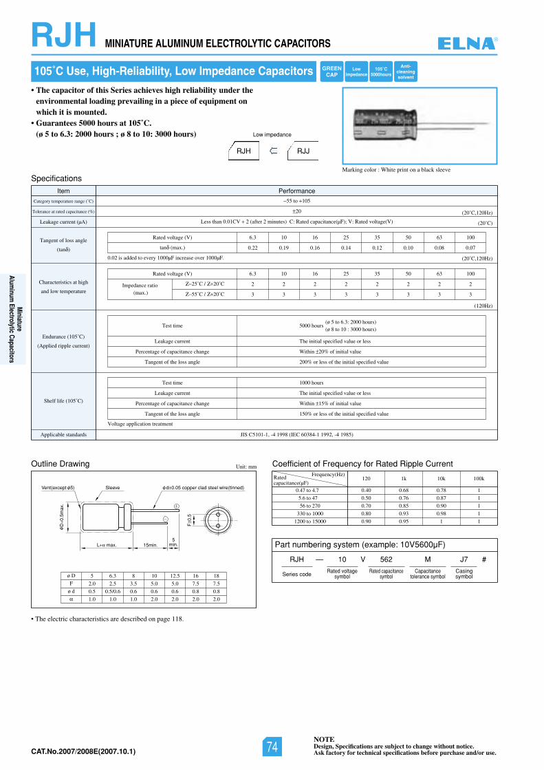
NOTEDesign, Specifications are subject to change without notice.Ask factory for technical specifications before purchase and/or use.CAT.No.2006/2007E(2006.10.1)
RJH MINIATURE ALUMINUM ELECTROLYTIC CAPACITORS
Outline Drawing Unit: mm
L max. 15min.
SleeveVent(except 5)
D0.
5max
.
F0.
5
d 0.05 copper clad steel wire(tinned)
5min.
ø D
F
ø d
5 6.3 8 10 12.5 16 18
2.0 2.5 3.5 5.0 5.0 7.5 7.5
0.5 0.5/0.6 0.6 0.6 0.6 0.8 0.8
1.0 1.0 1.0 2.0 2.0 2.0 2.0
105˚C Use, High-Reliability, Low Impedance Capacitors
Marking color : White print on a black sleeve
Specifications
Item Performance
Category temperature range (˚C)
Tolerance at rated capacitance (%)
Leakage current (µA)
Tangent of loss angle
(tan )
Characteristics at high
and low temperature
Endurance (105˚C)
(Applied ripple current)
Shelf life (105˚C)
)58914-,29911-48306CEI(89914-,1-1015CSIJsdradnatselbacilppA
55 to 105
20
Less than 0.01CV 2 (after 2 minutes) C: Rated capacitance(µF); V: Rated voltage(V) (20˚C)
(20˚C,120Hz)
(20˚C,120Hz)
(120Hz)
Test time
Leakage current
Percentage of capacitance change
Tangent of the loss angle
(ø 5 to 6.3: 2000 hours)5000 hours
(ø 8 to 10 : 3000 hours)
The initial specified value or less
Within 20% of initial value
200% or less of the initial specified value
Test time
Leakage current
Percentage of capacitance change
Tangent of the loss angle
1000 hours
The initial specified value or less
Within 15% of initial value
150% or less of the initial specified value
0013605535261013.6)V(egatlovdetaR
0.22 0.19 0.16 0.14 0.12 0.10 0.08 0.07tan (max.)
0013605535261013.6)V(egatlovdetaR
2 2 2 2 2 2 2 2
3 3 3 3 3 3 3 3
Impedance ratio(max.)
25˚C / 20˚C
55˚C / 20˚C
0.02 is added to every 1000µF increase over 1000µF.
Voltage application treatment
Coefficient of Frequency for Rated Ripple CurrentFrequency(Hz)
0.47 to 4.7
5.6 to 47
56 to 270
330 to 1000
1200 to 15000
120 1k 10k 100k
0.40 0.68 0.78 1
0.50 0.76 0.87 1
0.70 0.85 0.90 1
0.80 0.93 0.98 1
0.90 0.95 1 1
• The electric characteristics are described on page 118.
Ratedcapacitance(µF)
Part numbering system (example: 10V5600µF)
RJH — V
Series code
10 562 M
Rated voltagesymbol
Rated capacitancesymbol
Capacitancetolerance symbol
J7
Casingsymbol
#
• The capacitor of this Series achieves high reliability under the environmental loading prevailing in a piece of equipment on which it is mounted.
• Guarantees 5000 hours at 105˚C. (ø 5 to 6.3: 2000 hours ; ø 8 to 10: 3000 hours)
RJH RJJ
Low impedance
Anti-cleaningsolvent
105˚C5000hours
LowImpedance
GREENCAP
®
Miniature
Aluminum
Electrolytic Capacitors
NOTEDesign, Specifications are subject to change without notice.Ask factory for technical specifications before purchase and/or use.74CAT.No.2007/2008E(2007.10.1)
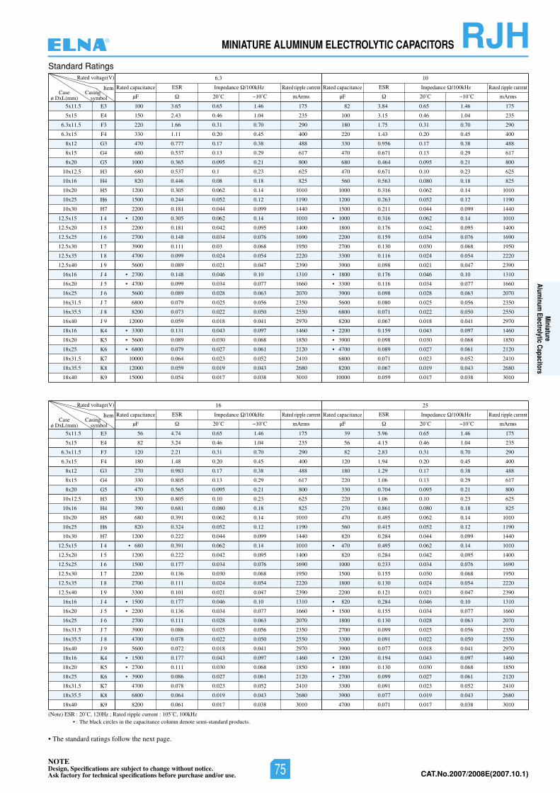
NOTEDesign, Specifications are subject to change without notice.Ask factory for technical specifications before purchase and/or use. CAT.No.2006/2007E(2006.10.1)
RJHMINIATURE ALUMINUM ELECTROLYTIC CAPACITORS
Standard Ratings
5x11.5
5x15
6.3x11.5
6.3x15
8x12
8x15
8x20
10x12.5
10x16
10x20
10x25
10x30
12.5x15
12.5x20
12.5x25
12.5x30
12.5x35
12.5x40
16x16
16x20
16x25
16x31.5
16x35.5
16x40
18x16
18x20
18x25
18x31.5
18x35.5
18x40
E3
E4
F3
F4
G3
G4
G5
H3
H4
H5
H6
H7
I 4
I 5
I 6
I 7
I 8
I 9
J 4
J 5
J 6
J 7
J 8
J 9
K4
K5
K6
K7
K8
K9
Rated voltage(V) 6.3 10
ItemCase
ø DxL(mm)
100 3.65 0.65 1.46 175
150 2.43 0.46 1.04 235
220 1.66 0.31 0.70 290
330 1.11 0.20 0.45 400
470 0.777 0.17 0.38 488
680 0.537 0.13 0.29 617
1000 0.365 0.095 0.21 800
680 0.537 0.1 0.23 625
820 0.446 0.08 0.18 825
1200 0.305 0.062 0.14 1010
1500 0.244 0.052 0.12 1190
2200 0.181 0.044 0.099 1440
• 1200 0.305 0.062 0.14 1010
2200 0.181 0.042 0.095 1400
2700 0.148 0.034 0.076 1690
3900 0.111 0.03 0.068 1950
4700 0.099 0.024 0.054 2220
5600 0.089 0.021 0.047 2390
• 2700 0.148 0.046 0.10 1310
• 4700 0.099 0.034 0.077 1660
5600 0.089 0.028 0.063 2070
6800 0.079 0.025 0.056 2350
8200 0.073 0.022 0.050 2550
12000 0.059 0.018 0.041 2970
• 3300 0.131 0.043 0.097 1460
• 5600 0.089 0.030 0.068 1850
• 6800 0.079 0.027 0.061 2120
10000 0.064 0.023 0.052 2410
12000 0.059 0.019 0.043 2680
15000 0.054 0.017 0.038 3010
82 3.84 0.65 1.46 175
100 3.15 0.46 1.04 235
180 1.75 0.31 0.70 290
220 1.43 0.20 0.45 400
330 0.956 0.17 0.38 488
470 0.671 0.13 0.29 617
680 0.464 0.095 0.21 800
470 0.671 0.10 0.23 625
560 0.563 0.080 0.18 825
1000 0.316 0.062 0.14 1010
1200 0.263 0.052 0.12 1190
1500 0.211 0.044 0.099 1440
• 1000 0.316 0.062 0.14 1010
1800 0.176 0.042 0.095 1400
2200 0.159 0.034 0.076 1690
2700 0.130 0.030 0.068 1950
3300 0.116 0.024 0.054 2220
3900 0.098 0.021 0.047 2390
• 1800 0.176 0.046 0.10 1310
• 3300 0.116 0.034 0.077 1660
3900 0.098 0.028 0.063 2070
5600 0.080 0.025 0.056 2350
6800 0.071 0.022 0.050 2550
8200 0.067 0.018 0.041 2970
• 2200 0.159 0.043 0.097 1460
• 3900 0.098 0.030 0.068 1850
• 4700 0.089 0.027 0.061 2120
6800 0.071 0.023 0.052 2410
8200 0.067 0.019 0.043 2680
10000 0.059 0.017 0.038 3010
ESR
µF 20˚C 10˚C mArms
ESR
µF 20˚C 10˚C mArmsCasing
symbol
ecnaticapacdetaRecnaticapacdetaR Impedance ecnadepmIzHk001/ /100kHzRated ripple current Rated ripple current
5x11.5
5x15
6.3x11.5
6.3x15
8x12
8x15
8x20
10x12.5
10x16
10x20
10x25
10x30
12.5x15
12.5x20
12.5x25
12.5x30
12.5x35
12.5x40
16x16
16x20
16x25
16x31.5
16x35.5
16x40
18x16
18x20
18x25
18x31.5
18x35.5
18x40
E3
E4
F3
F4
G3
G4
G5
H3
H4
H5
H6
H7
I 4
I 5
I 6
I 7
I 8
I 9
J 4
J 5
J 6
J 7
J 8
J 9
K4
K5
K6
K7
K8
K9
Rated voltage(V) 16 25
ItemCase
ø DxL(mm)
56 4.74 0.65 1.46 175
82 3.24 0.46 1.04 235
120 2.21 0.31 0.70 290
180 1.48 0.20 0.45 400
270 0.983 0.17 0.38 488
330 0.805 0.13 0.29 617
470 0.565 0.095 0.21 800
330 0.805 0.10 0.23 625
390 0.681 0.080 0.18 825
680 0.391 0.062 0.14 1010
820 0.324 0.052 0.12 1190
1200 0.222 0.044 0.099 1440
• 680 0.391 0.062 0.14 1010
1200 0.222 0.042 0.095 1400
1500 0.177 0.034 0.076 1690
2200 0.136 0.030 0.068 1950
2700 0.111 0.024 0.054 2220
3300 0.101 0.021 0.047 2390
• 1500 0.177 0.046 0.10 1310
• 2200 0.136 0.034 0.077 1660
2700 0.111 0.028 0.063 2070
3900 0.086 0.025 0.056 2350
4700 0.078 0.022 0.050 2550
5600 0.072 0.018 0.041 2970
• 1500 0.177 0.043 0.097 1460
• 2700 0.111 0.030 0.068 1850
• 3900 0.086 0.027 0.061 2120
4700 0.078 0.023 0.052 2410
6800 0.064 0.019 0.043 2680
8200 0.061 0.017 0.038 3010
39 5.96 0.65 1.46 175
56 4.15 0.46 1.04 235
82 2.83 0.31 0.70 290
120 1.94 0.20 0.45 400
180 1.29 0.17 0.38 488
220 1.06 0.13 0.29 617
330 0.704 0.095 0.21 800
220 1.06 0.10 0.23 625
270 0.861 0.080 0.18 825
470 0.495 0.062 0.14 1010
560 0.415 0.052 0.12 1190
820 0.284 0.044 0.099 1440
• 470 0.495 0.062 0.14 1010
820 0.284 0.042 0.095 1400
1000 0.233 0.034 0.076 1690
1500 0.155 0.030 0.068 1950
1800 0.130 0.024 0.054 2220
2200 0.121 0.021 0.047 2390
• 820 0.284 0.046 0.10 1310
• 1500 0.155 0.034 0.077 1660
1800 0.130 0.028 0.063 2070
2700 0.099 0.025 0.056 2350
3300 0.091 0.022 0.050 2550
3900 0.077 0.018 0.041 2970
• 1200 0.194 0.043 0.097 1460
• 1800 0.130 0.030 0.068 1850
• 2700 0.099 0.027 0.061 2120
3300 0.091 0.023 0.052 2410
3900 0.077 0.019 0.043 2680
4700 0.071 0.017 0.038 3010
ESR
µF 20˚C 10˚C mArms
ESR
µF 20˚C 10˚C mArmsCasing
symbol
ecnaticapacdetaRecnaticapacdetaR Impedance ecnadepmIzHk001/ /100kHzRated ripple current Rated ripple current
(Note) ESR : 20˚C, 120Hz ; Rated ripple current : 105˚C, 100kHz• : The black circles in the capacitance column denote semi-standard products.
• The standard ratings follow the next page.
®
Miniature
Aluminum
Electrolytic Capacitors
NOTEDesign, Specifications are subject to change without notice.Ask factory for technical specifications before purchase and/or use. 75 CAT.No.2007/2008E(2007.10.1)
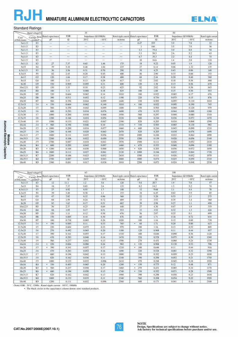
NOTEDesign, Specifications are subject to change without notice.Ask factory for technical specifications before purchase and/or use.CAT.No.2006/2007E(2006.10.1)
RJH MINIATURE ALUMINUM ELECTROLYTIC CAPACITORS
Standard Ratings
5x11.5
5x11.5
5x11.5
5x11.5
5x11.5
5x11.5
5x11.5
5x15
6.3x11.5
6.3x15
8x12
8x15
8x20
10x12.5
10x16
10x20
10x25
10x30
12.5x15
12.5x20
12.5x25
12.5x30
12.5x35
12.5x40
16x16
16x20
16x25
16x31.5
16x35.5
16x40
18x16
18x20
18x25
18x31.5
18x35.5
18x40
E3
E3
E3
E3
E3
E3
E3
E4
F3
F4
G3
G4
G5
H3
H4
H5
H6
H7
I 4
I 5
I 6
I 7
I 8
I 9
J 4
J 5
J 6
J 7
J 8
J 9
K4
K5
K6
K7
K8
K9
Rated voltage(V) 35 50
ItemCaseø DxL(mm)
— — — — —
— — — — —
— — — — —
— — — — —
— — — — —
— — — — —
27 7.37 0.65 1.46 175
39 5.10 0.46 1.04 235
56 3.56 0.31 0.70 290
82 2.43 0.20 0.45 400
120 1.66 0.17 0.38 488
180 1.11 0.13 0.29 617
220 0.905 0.095 0.21 800
150 1.33 0.10 0.23 625
180 1.11 0.080 0.18 825
330 0.604 0.062 0.14 1010
390 0.511 0.052 0.12 1190
560 0.356 0.044 0.099 1440
• 330 0.604 0.062 0.140 1010
560 0.356 0.042 0.095 1400
680 0.293 0.034 0.076 1690
1000 0.200 0.030 0.068 1950
1200 0.166 0.024 0.054 2220
1500 0.133 0.021 0.047 2390
• 560 0.356 0.046 0.10 1310
• 1000 0.200 0.034 0.077 1660
1200 0.166 0.028 0.063 2070
1800 0.111 0.025 0.056 2350
2200 0.106 0.022 0.050 2550
2700 0.087 0.018 0.041 2970
• 680 0.293 0.043 0.097 1460
• 1200 0.166 0.030 0.068 1850
• 1800 0.111 0.027 0.061 2120
2200 0.106 0.023 0.052 2410
2700 0.087 0.019 0.043 2680
3300 0.081 0.017 0.038 3010
0.47 353 3.9 7.8 22
1 166 3.5 7.0 36
2.2 75.4 3.0 6.0 54
3.3 50.3 2.6 5.2 63
4.7 35.3 2.2 4.4 75
10 16.6 1.4 2.8 110
18 9.22 0.95 1.9 120
27 6.14 0.66 1.32 135
39 4.25 0.43 0.86 148
56 2.96 0.33 0.66 153
68 2.44 0.20 0.40 360
82 2.02 0.18 0.36 460
120 1.38 0.13 0.26 670
82 2.02 0.18 0.36 443
100 1.66 0.15 0.30 553
180 0.922 0.085 0.17 676
220 0.754 0.075 0.15 876
330 0.503 0.055 0.110 1010
• 180 0.922 0.095 0.190 745
330 0.503 0.060 0.120 979
470 0.353 0.044 0.088 1180
560 0.297 0.040 0.080 1310
680 0.244 0.036 0.072 1470
820 0.203 0.034 0.068 1590
• 330 0.503 0.065 0.130 982
• 680 0.244 0.045 0.090 1210
820 0.203 0.038 0.076 1490
1000 0.166 0.032 0.064 1890
1200 0.139 0.028 0.056 2140
1500 0.111 0.026 0.052 2410
• 470 0.353 0.048 0.096 1180
• 820 0.203 0.036 0.072 1450
• 1000 0.166 0.032 0.064 1720
1500 0.111 0.026 0.052 1970
1800 0.074 0.025 0.050 2310
2200 0.073 0.024 0.048 2530
ESR
µF 20˚C 10˚C mArmsCasing
symbol
Rated capacitance Impedance /100kHz Rated ripple current ESR
µF 20˚C 10˚C mArmsRated capacitance Impedance /100kHz Rated ripple current
5x11.5
5x15
6.3x11.5
6.3x15
8x12
8x15
8x20
10x12.5
10x16
10x20
10x25
10x30
12.5x15
12.5x20
12.5x25
12.5x30
12.5x35
12.5x40
16x16
16x20
16x25
16x31.5
16x35.5
16x40
18x16
18x20
18x25
18x31.5
18x35.5
18x40
E3
E4
F3
F4
G3
G4
G5
H3
H4
H5
H6
H7
I 4
I 5
I 6
I 7
I 8
I 9
J 4
J 5
J 6
J 7
J 8
J 9
K4
K5
K6
K7
K8
K9
Rated voltage(V) 63 100
ItemCaseø DxL(mm)
12 11.1 1.2 3.6 120
18 7.37 0.85 2.6 135
27 4.92 0.55 1.7 148
39 3.40 0.38 1.1 153
47 2.82 0.32 0.96 360
68 1.95 0.24 0.72 469
82 1.62 0.17 0.51 682
56 2.37 0.23 0.69 448
68 1.95 0.17 0.51 553
120 1.11 0.12 0.36 676
150 0.885 0.10 0.30 876
180 0.738 0.085 0.26 1020
• 150 0.885 0.11 0.33 745
220 0.604 0.075 0.23 979
270 0.492 0.065 0.20 1180
390 0.341 0.055 0.17 1310
470 0.283 0.048 0.14 1470
560 0.237 0.042 0.13 1590
• 220 0.604 0.080 0.24 982
• 390 0.341 0.057 0.17 1210
470 0.283 0.052 0.16 1490
680 0.196 0.042 0.13 1890
820 0.162 0.036 0.11 2140
1000 0.133 0.032 0.096 2410
• 330 0.403 0.065 0.20 1200
• 560 0.237 0.058 0.17 1460
• 680 0.196 0.050 0.15 1740
820 0.162 0.042 0.13 1990
1000 0.133 0.035 0.11 2340
1200 0.111 0.032 0.096 2560
5.6 20.7 1.9 7.6 57
8.2 14.2 1.3 5.2 74
12 9.68 1.1 4.4 78
18 6.45 0.62 2.5 85
22 5.28 0.53 2.1 275
33 3.52 0.35 1.4 360
39 2.98 0.27 1.1 490
27 4.30 0.47 1.9 319
33 3.52 0.32 1.3 424
56 2.07 0.25 0.1 499
68 1.71 0.18 0.72 634
100 1.16 0.15 0.60 739
• 68 1.71 0.20 0.80 613
100 1.16 0.13 0.52 805
120 0.968 0.11 0.44 857
180 0.646 0.090 0.36 1120
220 0.528 0.075 0.30 1240
270 0.431 0.060 0.24 1330
• 120 0.968 0.130 0.52 706
• 180 0.646 0.11 0.44 916
220 0.528 0.081 0.32 1290
330 0.352 0.059 0.23 1630
390 0.298 0.052 0.21 1750
470 0.248 0.045 0.18 1920
• 150 0.775 0.12 0.48 871
• 270 0.431 0.085 0.34 1170
• 330 0.352 0.071 0.28 1500
390 0.298 0.058 0.23 1630
560 0.208 0.054 0.22 1920
680 0.171 0.041 0.16 2100
ESR
µF 20˚C 10˚C mArmsCasing
symbol
Rated capacitance Impedance /100kHz Rated ripple current ESR
µF 20˚C 10˚C mArmsRated capacitance Impedance /100kHz Rated ripple current
(Note) ESR : 20˚C, 120Hz ; Rated ripple current : 105˚C, 100kHz• : The black circles in the capacitance column denote semi-standard products.
®
Miniature
Aluminum
Electrolytic Capacitors
NOTEDesign, Specifications are subject to change without notice.Ask factory for technical specifications before purchase and/or use.76CAT.No.2007/2008E(2007.10.1)
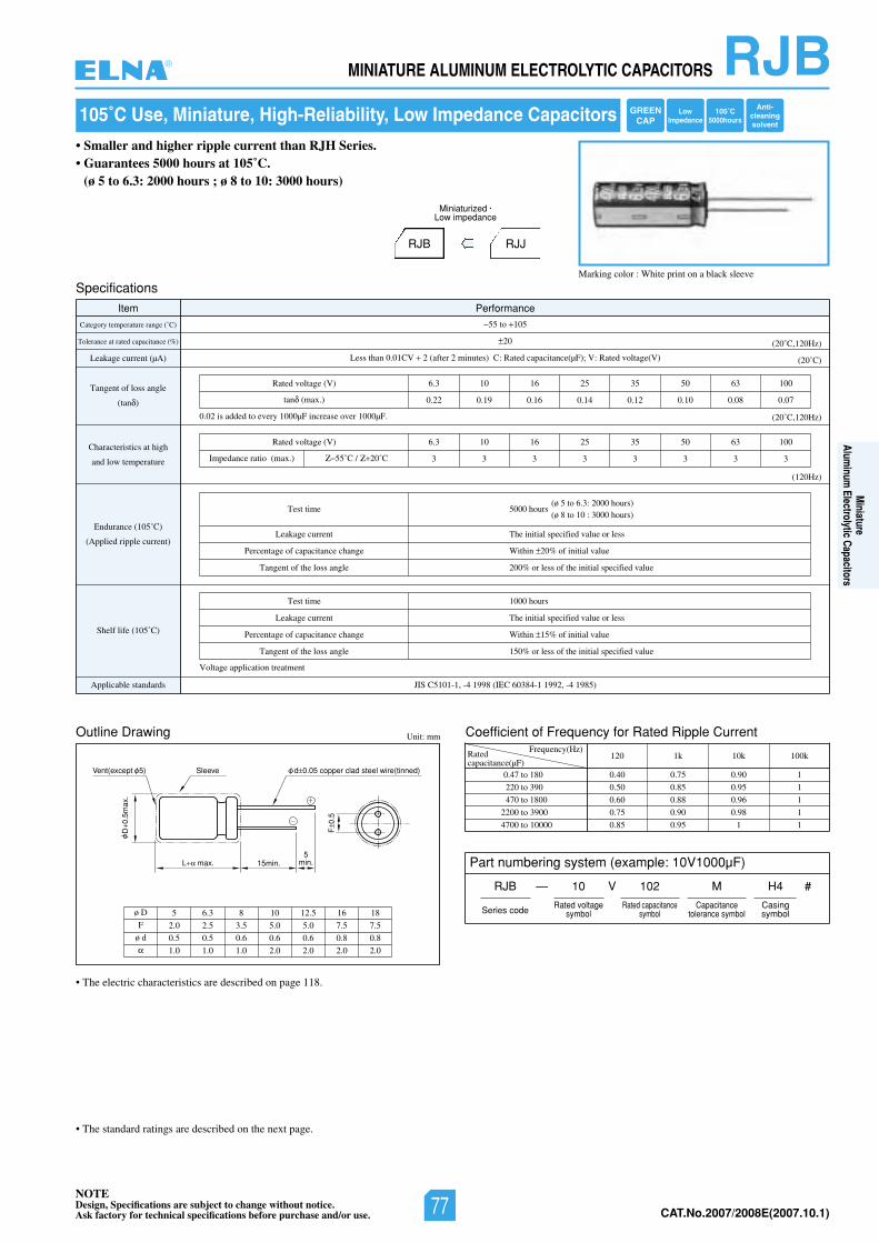
NOTEDesign, Specifications are subject to change without notice.Ask factory for technical specifications before purchase and/or use. CAT.No.2006/2007E(2006.10.1)
RJBMINIATURE ALUMINUM ELECTROLYTIC CAPACITORS
Outline Drawing Unit: mm
L max. 15min.
SleeveVent(except 5)
D0.
5max
.
F0.
5
d 0.05 copper clad steel wire(tinned)
5min.
ø D
F
ø d
5 6.3 8 10 12.5 16 18
2.0 2.5 3.5 5.0 5.0 7.5 7.5
0.5 0.5 0.6 0.6 0.6 0.8 0.8
1.0 1.0 1.0 2.0 2.0 2.0 2.0
105˚C Use, Miniature, High-Reliability, Low Impedance Capacitors
Marking color : White print on a black sleeve
Coefficient of Frequency for Rated Ripple CurrentFrequency(Hz)
0.47 to 180
220 to 390
470 to 1800
2200 to 3900
4700 to 10000
120 1k 10k 100k
0.40 0.75 0.90 1
0.50 0.85 0.95 1
0.60 0.88 0.96 1
0.75 0.90 0.98 1
0.85 0.95 1 1
• The electric characteristics are described on page 118.
Specifications
Item Performance
Category temperature range (˚C)
Tolerance at rated capacitance (%)
Leakage current (µA)
Tangent of loss angle
(tan )
Characteristics at high
and low temperature
Endurance (105˚C)
(Applied ripple current)
Shelf life (105˚C)
)58914-,29911-48306CEI(89914-,1-1015CSIJsdradnatselbacilppA
55 to 105
20
Less than 0.01CV 2 (after 2 minutes) C: Rated capacitance(µF); V: Rated voltage(V) (20˚C)
(20˚C,120Hz)
(20˚C,120Hz)
(120Hz)
Test time
Leakage current
Percentage of capacitance change
Tangent of the loss angle
(ø 5 to 6.3: 2000 hours)5000 hours
(ø 8 to 10 : 3000 hours)
The initial specified value or less
Within 20% of initial value
200% or less of the initial specified value
Test time
Leakage current
Percentage of capacitance change
Tangent of the loss angle
1000 hours
The initial specified value or less
Within 15% of initial value
150% or less of the initial specified value
0013605535261013.6)V(egatlovdetaR
0.22 0.19 0.16 0.14 0.12 0.10 0.08 0.07tan (max.)
0013605535261013.6)V(egatlovdetaR
3 3 3 3 3 3 3 3Impedance ratio (max.) 55˚C / 20˚C
0.02 is added to every 1000µF increase over 1000µF.
Voltage application treatment
Ratedcapacitance(µF)
• The standard ratings are described on the next page.
Part numbering system (example: 10V1000µF)
RJB — V
Series code
10 102 M
Rated voltagesymbol
Rated capacitancesymbol
Capacitancetolerance symbol
H4
Casingsymbol
#
• Smaller and higher ripple current than RJH Series.• Guarantees 5000 hours at 105˚C.
(ø 5 to 6.3: 2000 hours ; ø 8 to 10: 3000 hours)
RJB RJJ
Miniaturized •
Low impedance
Anti-cleaningsolvent
105˚C5000hours
LowImpedance
GREENCAP
®
Miniature
Aluminum
Electrolytic Capacitors
NOTEDesign, Specifications are subject to change without notice.Ask factory for technical specifications before purchase and/or use. 77 CAT.No.2007/2008E(2007.10.1)
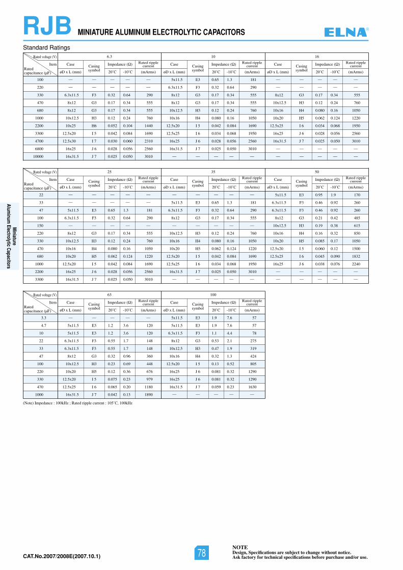
NOTEDesign, Specifications are subject to change without notice.Ask factory for technical specifications before purchase and/or use.CAT.No.2006/2007E(2006.10.1)
RJB MINIATURE ALUMINUM ELECTROLYTIC CAPACITORS
(Note) Impedance : 100kHz ; Rated ripple current : 105˚C, 100kHz
Standard Ratings
100
220
330
470
680
1000
2200
3300
4700
6800
10000
Rated voltage (V) 61016.3
Item
— — — — —
— — — — —
6.3x11.5 F3 0.32 0.64 290
8x12 G3 0.17 0.34 555
8x12 G3 0.17 0.34 555
10x12.5 H3 0.12 0.24 760
10x25 H6 0.052 0.104 1440
12.5x20 I 5 0.042 0.084 1690
12.5x30 I 7 0.030 0.060 2310
16x25 J 6 0.028 0.056 2560
16x31.5 J 7 0.025 0.050 3010
5x11.5 E3 0.65 1.3 181
6.3x11.5 F3 0.32 0.64 290
8x12 G3 0.17 0.34 555
8x12 G3 0.17 0.34 555
10x12.5 H3 0.12 0.24 760
10x16 H4 0.080 0.16 1050
12.5x20 I 5 0.042 0.084 1690
12.5x25 I 6 0.034 0.068 1950
16x25 J 6 0.028 0.056 2560
16x31.5 J 7 0.025 0.050 3010
— — — — —
— — — — —
— — — — —
8x12 G3 0.17 0.34 555
10x12.5 H3 0.12 0.24 760
10x16 H4 0.080 0.16 1050
10x20 H5 0.062 0.124 1220
12.5x25 I 6 0.034 0.068 1950
16x25 J 6 0.028 0.056 2560
16x31.5 J 7 0.025 0.050 3010
— — — — —
— — — — —
Ratedcapacitance (µF)
Case
øD x L (mm)
Casingsymbol
Rated ripplecurrent
(mArms)
Impedance ( )
20˚C -10˚C
Case
øD x L (mm)
Casingsymbol
Rated ripplecurrent
(mArms)
Impedance ( )
20˚C -10˚C
Case
øD x L (mm)
Casingsymbol
Rated ripplecurrent
(mArms)
Impedance ( )
20˚C -10˚C
22
33
47
100
150
220
330
470
680
1000
2200
3300
Rated voltage (V) 055325
Item
— — — — —
— — — — —
5x11.5 E3 0.65 1.3 181
6.3x11.5 F3 0.32 0.64 290
— — — — —
8x12 G3 0.17 0.34 555
10x12.5 H3 0.12 0.24 760
10x16 H4 0.080 0.16 1050
10x20 H5 0.062 0.124 1220
12.5x20 I 5 0.042 0.084 1690
16x25 J 6 0.028 0.056 2560
16x31.5 J 7 0.025 0.050 3010
— — — — —
5x11.5 E3 0.65 1.3 181
6.3x11.5 F3 0.32 0.64 290
8x12 G3 0.17 0.34 555
— — — — —
10x12.5 H3 0.12 0.24 760
10x16 H4 0.080 0.16 1050
10x20 H5 0.062 0.124 1220
12.5x20 I 5 0.042 0.084 1690
12.5x25 I 6 0.034 0.068 1950
16x31.5 J 7 0.025 0.050 3010
— — — — —
5x11.5 E3 0.95 1.9 170
6.3x11.5 F3 0.46 0.92 260
6.3x11.5 F3 0.46 0.92 260
8x12 G3 0.21 0.42 485
10x12.5 H3 0.19 0.38 615
10x16 H4 0.16 0.32 850
10x20 H5 0.085 0.17 1050
12.5x20 I 5 0.060 0.12 1500
12.5x25 I 6 0.045 0.090 1832
16x25 J 6 0.038 0.076 2240
— — — — —
— — — — —
Ratedcapacitance (µF)
Case
øD x L (mm)
Casingsymbol
Rated ripplecurrent
(mArms)
Impedance ( )
20˚C -10˚C
Case
øD x L (mm)
Casingsymbol
Rated ripplecurrent
(mArms)
Impedance ( )
20˚C -10˚C
Case
øD x L (mm)
Casingsymbol
Rated ripplecurrent
(mArms)
Impedance ( )
20˚C -10˚C
3.3
4.7
10
22
33
47
100
220
330
470
1000
Rated voltage (V) 10063
Item
— — — — —
5x11.5 E3 1.2 3.6 120
5x11.5 E3 1.2 3.6 120
6.3x11.5 F3 0.55 1.7 148
6.3x11.5 F3 0.55 1.7 148
8x12 G3 0.32 0.96 360
10x12.5 H3 0.23 0.69 448
10x20 H5 0.12 0.36 676
12.5x20 I 5 0.075 0.23 979
12.5x25 I 6 0.065 0.20 1180
16x31.5 J 7 0.042 0.13 1890
5x11.5 E3 1.9 7.6 57
5x11.5 E3 1.9 7.6 57
6.3x11.5 F3 1.1 4.4 78
8x12 G3 0.53 2.1 275
10x12.5 H3 0.47 1.9 319
10x16 H4 0.32 1.3 424
12.5x20 I 5 0.13 0.52 805
16x25 J 6 0.081 0.32 1290
16x25 J 6 0.081 0.32 1290
16x31.5 J 7 0.059 0.23 1630
— — — — —
Ratedcapacitance (µF)
Case
øD x L (mm)
Casingsymbol
Rated ripplecurrent
(mArms)
Impedance ( )
20˚C -10˚C
Case
øD x L (mm)
Casingsymbol
Rated ripplecurrent
(mArms)
Impedance ( )
20˚C -10˚C
®
Miniature
Aluminum
Electrolytic Capacitors
NOTEDesign, Specifications are subject to change without notice.Ask factory for technical specifications before purchase and/or use.78CAT.No.2007/2008E(2007.10.1)
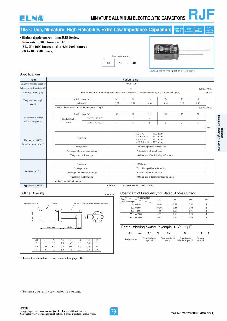
NOTEDesign, Specifications are subject to change without notice.Ask factory for technical specifications before purchase and/or use. CAT.No.2006/2007E(2006.10.1)
RJFMINIATURE ALUMINUM ELECTROLYTIC CAPACITORS
105˚C Use, Miniature, High-Reliability, Extra Low Impedance Capacitors
• Higher ripple current than RJB Series.• Guarantees 5000 hours at 105˚C.
(5L, 7L: 1000 hours ; ø 5 to 6.3: 2000 hours ; ø 8 to 10: 3000 hours)
RJF RJB
Low impedance
Marking color : White print on a black sleeve
Outline Drawing Unit: mm
L max. 15min.
SleeveVent(except 5)
D0.
5max
.
F0.
5
d 0.05 copper clad steel wire(tinned)
5min.
ø D
F
ø d
4 5 6.3 8 10 12.5 16
1.5 2.0 2.5 3.5 5.0 5.0 7.5
0.45 0.5 0.5 0.6 0.6 0.6 0.8
1.0 1.0 1.0 1.0 2.0 2.0 2.0
Coefficient of Frequency for Rated Ripple CurrentFrequency(Hz)
5.6 to 180
220 to 390
470 to 1800
2200 to 3900
4700 to 6800
120 1k 10k 100k
0.40 0.75 0.90 1
0.50 0.85 0.94 1
0.60 0.87 0.95 1
0.75 0.90 0.95 1
0.85 0.95 0.98 1
• The electric characteristics are described on page 118.
Specifications
Item Performance
Category temperature range (˚C)
Tolerance at rated capacitance (%)
Leakage current (µA)
Tangent of loss angle
(tan )
Characteristics at high
and low temperature
Endurance (105˚C)
(Applied ripple current)
Shelf life (105˚C)
)58914-,29911-48306CEI(89914-,1-1015CSIJsdradnatselbacilppA
40 to 105
20
Less than 0.01CV or 3 whichever is larger (after 2 minutes) C: Rated capacitance(µF); V: Rated voltage(V) (20˚C)
(20˚C,120Hz)
(20˚C,120Hz)
(120Hz)
Test time
Leakage current
Percentage of capacitance change
Tangent of the loss angle
5L & 7L : 1000 hoursø 5 & ø 6.3 : 2000 hoursø 8 & ø 10 : 3000 hoursø 12.5 & ø 16 : 5000 hours
The initial specified value or less
Within 25% of initial value
200% or less of the initial specified value
Test time
Leakage current
Percentage of capacitance change
Tangent of the loss angle
1000 hours
The initial specified value or less
Within 25% of initial value
200% or less of the initial specified value
05535261013.6)V(egatlovdetaR
0.22 0.19 0.16 0.14 0.12 0.10tan (max.)
05535261013.6)V(egatlovdetaR
2 2 2 2 2 2
3 3 3 3 3 3
Impedance ratio(max.)
25˚C / 20˚C
40˚C / 20˚C
0.02 is added to every 1000µF increase over 1000µF.
Voltage application treatment
Ratedcapacitance(µF)
• The standard ratings are described on the next page.
Part numbering system (example: 10V1000µF)
RJF — V
Series code
10 102 M
Rated voltagesymbol
Rated capacitancesymbol
Capacitancetolerance symbol
H4
Casingsymbol
#
Anti-cleaningsolvent
105˚C5000hours
LowImpedance
GREENCAP
®
Miniature
Aluminum
Electrolytic Capacitors
NOTEDesign, Specifications are subject to change without notice.Ask factory for technical specifications before purchase and/or use. 79 CAT.No.2007/2008E(2007.10.1)
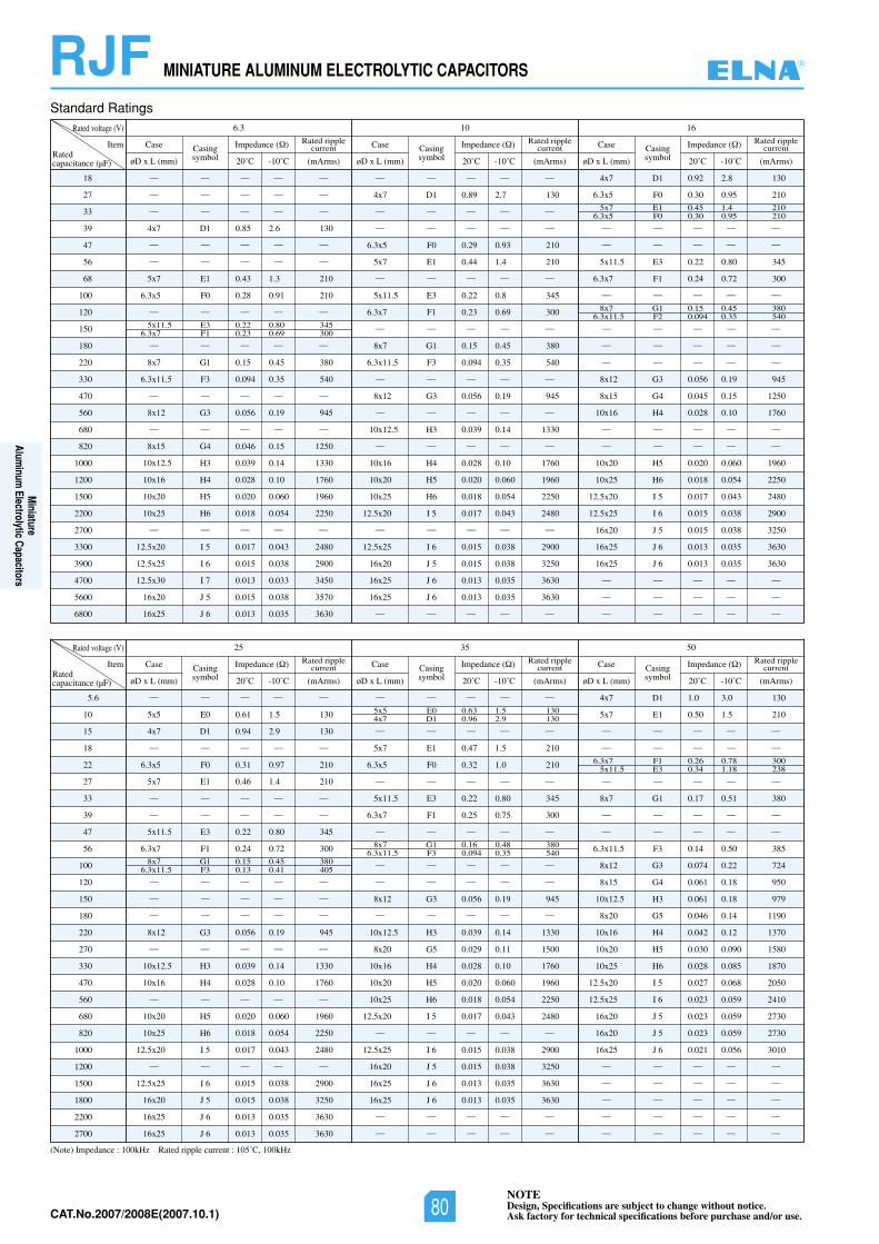
NOTEDesign, Specifications are subject to change without notice.Ask factory for technical specifications before purchase and/or use.CAT.No.2006/2007E(2006.10.1)
RJF MINIATURE ALUMINUM ELECTROLYTIC CAPACITORS
(Note) Impedance : 100kHz Rated ripple current : 105˚C, 100kHz
Standard Ratings
18
27
33
39
47
56
68
100
120
150
180
220
330
470
560
680
820
1000
1200
1500
2200
2700
3300
3900
4700
5600
6800
Rated voltage (V) 61016.3
Item
— — — — —
— — — — —
— — — — —
4x7 D1 0.85 2.6 130
— — — — —
— — — — —
5x7 E1 0.43 1.3 210
6.3x5 F0 0.28 0.91 210
— — — — —
— — — — —
8x7 G1 0.15 0.45 380
6.3x11.5 F3 0.094 0.35 540
— — — — —
8x12 G3 0.056 0.19 945
— — — — —
8x15 G4 0.046 0.15 1250
10x12.5 H3 0.039 0.14 1330
10x16 H4 0.028 0.10 1760
10x20 H5 0.020 0.060 1960
10x25 H6 0.018 0.054 2250
— — — — —
12.5x20 I 5 0.017 0.043 2480
12.5x25 I 6 0.015 0.038 2900
12.5x30 I 7 0.013 0.033 3450
16x20 J 5 0.015 0.038 3570
16x25 J 6 0.013 0.035 3630
— — — — —
4x7 D1 0.89 2.7 130
— — — — —
— — — — —
6.3x5 F0 0.29 0.93 210
5x7 E1 0.44 1.4 210
— — — — —
5x11.5 E3 0.22 0.8 345
6.3x7 F1 0.23 0.69 300
— — — — —
8x7 G1 0.15 0.45 380
6.3x11.5 F3 0.094 0.35 540
— — — — —
8x12 G3 0.056 0.19 945
— — — — —
10x12.5 H3 0.039 0.14 1330
— — — — —
10x16 H4 0.028 0.10 1760
10x20 H5 0.020 0.060 1960
10x25 H6 0.018 0.054 2250
12.5x20 I 5 0.017 0.043 2480
— — — — —
12.5x25 I 6 0.015 0.038 2900
16x20 J 5 0.015 0.038 3250
16x25 J 6 0.013 0.035 3630
16x25 J 6 0.013 0.035 3630
— — — — —
4x7 D1 0.92 2.8 130
6.3x5 F0 0.30 0.95 210
— — — — —
— — — — —
5x11.5 E3 0.22 0.80 345
6.3x7 F1 0.24 0.72 300
— — — — —
— — — — —
— — — — —
— — — — —
8x12 G3 0.056 0.19 945
8x15 G4 0.045 0.15 1250
10x16 H4 0.028 0.10 1760
— — — — —
— — — — —
10x20 H5 0.020 0.060 1960
10x25 H6 0.018 0.054 2250
12.5x20 I 5 0.017 0.043 2480
12.5x25 I 6 0.015 0.038 2900
16x20 J 5 0.015 0.038 3250
16x25 J 6 0.013 0.035 3630
16x25 J 6 0.013 0.035 3630
— — — — —
— — — — —
— — — — —
5x11.5 E3 0.22 0.80 3456.3x7 F1 0.23 0.69 300
5x7 E1 0.45 1.4 2106.3x5 F0 0.30 0.95 210
8x7 G1 0.15 0.45 3806.3x11.5 F2 0.094 0.35 540
Ratedcapacitance (µF)
Case
øD x L (mm)
Casingsymbol
Rated ripplecurrent
(mArms)
Impedance ( )
20˚C -10˚C
Case
øD x L (mm)
Casingsymbol
Rated ripplecurrent
(mArms)
Impedance ( )
20˚C -10˚C
Case
øD x L (mm)
Casingsymbol
Rated ripplecurrent
(mArms)
Impedance ( )
20˚C -10˚C
5.6
10
15
18
22
27
33
39
47
56
100
120
150
180
220
270
330
470
560
680
820
1000
1200
1500
1800
2200
2700
Rated voltage (V) 055325
Item
— — — — —
5x5 E0 0.61 1.5 130
4x7 D1 0.94 2.9 130
— — — — —
6.3x5 F0 0.31 0.97 210
5x7 E1 0.46 1.4 210
— — — — —
— — — — —
5x11.5 E3 0.22 0.80 345
6.3x7 F1 0.24 0.72 300
— — — — —
— — — — —
— — — — —
8x12 G3 0.056 0.19 945
— — — — —
10x12.5 H3 0.039 0.14 1330
10x16 H4 0.028 0.10 1760
— — — — —
10x20 H5 0.020 0.060 1960
10x25 H6 0.018 0.054 2250
12.5x20 I 5 0.017 0.043 2480
— — — — —
12.5x25 I 6 0.015 0.038 2900
16x20 J 5 0.015 0.038 3250
16x25 J 6 0.013 0.035 3630
16x25 J 6 0.013 0.035 3630
— — — — —
— — — — —
5x7 E1 0.47 1.5 210
6.3x5 F0 0.32 1.0 210
— — — — —
5x11.5 E3 0.22 0.80 345
6.3x7 F1 0.25 0.75 300
— — — — —
— — — — —
— — — — —
8x12 G3 0.056 0.19 945
— — — — —
10x12.5 H3 0.039 0.14 1330
8x20 G5 0.029 0.11 1500
10x16 H4 0.028 0.10 1760
10x20 H5 0.020 0.060 1960
10x25 H6 0.018 0.054 2250
12.5x20 I 5 0.017 0.043 2480
— — — — —
12.5x25 I 6 0.015 0.038 2900
16x20 J 5 0.015 0.038 3250
16x25 J 6 0.013 0.035 3630
16x25 J 6 0.013 0.035 3630
— — — — —
— — — — —
4x7 D1 1.0 3.0 130
5x7 E1 0.50 1.5 210
— — — — —
— — — — —
— — — — —
8x7 G1 0.17 0.51 380
— — — — —
— — — — —
6.3x11.5 F3 0.14 0.50 385
8x12 G3 0.074 0.22 724
8x15 G4 0.061 0.18 950
10x12.5 H3 0.061 0.18 979
8x20 G5 0.046 0.14 1190
10x16 H4 0.042 0.12 1370
10x20 H5 0.030 0.090 1580
10x25 H6 0.028 0.085 1870
12.5x20 I 5 0.027 0.068 2050
12.5x25 I 6 0.023 0.059 2410
16x20 J 5 0.023 0.059 2730
16x20 J 5 0.023 0.059 2730
16x25 J 6 0.021 0.056 3010
— — — — —
— — — — —
— — — — —
— — — — —
— — — — —
8x7 G1 0.15 0.45 3806.3x11.5 F3 0.13 0.41 405
8x7 G1 0.16 0.48 3806.3x11.5 F3 0.094 0.35 540
6.3x7 F1 0.26 0.78 3005x11.5 E3 0.34 1.18 238
Ratedcapacitance (µF)
Case
øD x L (mm)
Casingsymbol
Rated ripplecurrent
(mArms)
Impedance ( )
20˚C -10˚C
Case
øD x L (mm)
Casingsymbol
Rated ripplecurrent
(mArms)
Impedance ( )
20˚C -10˚C
Case
øD x L (mm)
Casingsymbol
Rated ripplecurrent
(mArms)
Impedance ( )
20˚C -10˚C
5x5 E0 0.63 1.5 1304x7 D1 0.96 2.9 130
®
Miniature
Aluminum
Electrolytic Capacitors
NOTEDesign, Specifications are subject to change without notice.Ask factory for technical specifications before purchase and/or use.80CAT.No.2007/2008E(2007.10.1)
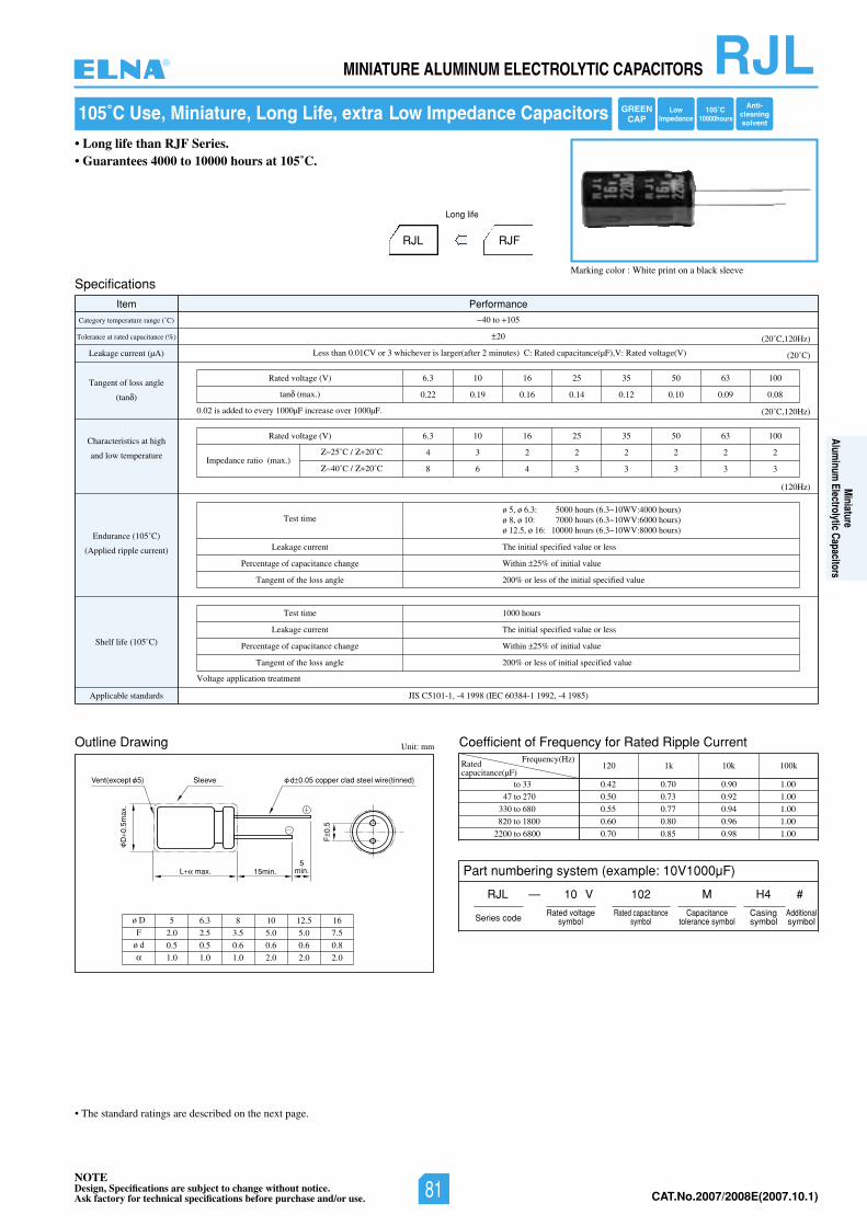
NOTEDesign, Specifications are subject to change without notice.Ask factory for technical specifications before purchase and/or use. CAT.No.2006/2007E(2006.10.1)
RJLMINIATURE ALUMINUM ELECTROLYTIC CAPACITORS
Outline Drawing Unit: mm
L max. 15min.
SleeveVent(except 5)
D0.
5max
.
F0.
5
d 0.05 copper clad steel wire(tinned)
5min.
ø D
F
ø d
5 6.3 8 10 12.5 16
2.0 2.5 3.5 5.0 5.0 7.5
0.5 0.5 0.6 0.6 0.6 0.8
1.0 1.0 1.0 2.0 2.0 2.0
105˚C Use, Miniature, Long Life, extra Low Impedance Capacitors
Marking color : White print on a black sleeve
Coefficient of Frequency for Rated Ripple CurrentFrequency(Hz)
to 33
47 to 270
330 to 680
820 to 1800
2200 to 6800
120 1k 10k 100k
0.42 0.70 0.90 1.00
0.50 0.73 0.92 1.00
0.55 0.77 0.94 1.00
0.60 0.80 0.96 1.00
0.70 0.85 0.98 1.00
Specifications
Item Performance
Category temperature range (˚C)
Tolerance at rated capacitance (%)
Leakage current (µA)
Tangent of loss angle
(tan )
Characteristics at high
and low temperature
Endurance (105˚C)
(Applied ripple current)
Shelf life (105˚C)
JIS C5101-1, -4 1998 (IEC 60384-1 1992, -4 1985)sdradnatselbacilppA
40 to 105
20
Less than 0.01CV or 3 whichever is larger(after 2 minutes) C: Rated capacitance(µF),V: Rated voltage(V) (20˚C)
(20˚C,120Hz)
(20˚C,120Hz)
(120Hz)
Test time
Leakage current
Percentage of capacitance change
Tangent of the loss angle
The initial specified value or less
Within 25% of initial value
200% or less of the initial specified value
Test time
Leakage current
Percentage of capacitance change
Tangent of the loss angle
1000 hours
The initial specified value or less
Within 5% of initial value
200% or less of initial specified value
0013605535261013.6)V(egatlovdetaR
0.22 0.19 0.16 0.14 0.12 0.10 0.09 0.08tan (max.)
0013605535261013.6)V(egatlovdetaR
4 3 2 2 2 2 2 2Impedance ratio (max.)
25˚C / 20˚C
8 6 4 3 3 3 3 340˚C / 20˚C
0.02 is added to every 1000µF increase over 1000µF.
Voltage application treatment
Ratedcapacitance(µF)
• The standard ratings are described on the next page.
Part numbering system (example: 10V1000µF)
RJL — V
Series code
10 102 M
Rated voltagesymbol
Rated capacitancesymbol
Capacitancetolerance symbol
H4
Casing Additionalsymbol symbol
#
• Long life than RJF Series.• Guarantees 4000 to 10000 hours at 105˚C.
RJL RJF
Long life
Anti-cleaningsolvent
105˚C10000hours
LowImpedance
GREENCAP
ø 5, ø 6.3: 5000 hours (6.3~10WV:4000 hours)ø 8, ø 10: 7000 hours (6.3~10WV:6000 hours)ø 12.5, ø 16: 10000 hours (6.3~10WV:8000 hours)
®
Miniature
Aluminum
Electrolytic Capacitors
NOTEDesign, Specifications are subject to change without notice.Ask factory for technical specifications before purchase and/or use. 81 CAT.No.2007/2008E(2007.10.1)
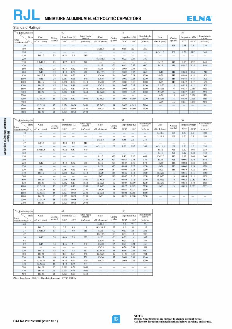
NOTEDesign, Specifications are subject to change without notice.Ask factory for technical specifications before purchase and/or use.CAT.No.2006/2007E(2006.10.1)
RJL MINIATURE ALUMINUM ELECTROLYTIC CAPACITORS
(Note) Impedance : 100kHz ; Rated ripple current : 105˚C, 100kHz
Standard Ratings
56
100
120
150
220
330
470
560
680
820
1000
1200
1500
1800
2200
2700
3300
3900
4700
5600
6800
Rated voltage (V) 61016.3
ItemRatedcapacitance (µF)
Case
øD x L (mm)
Casingsymbol
Rated ripplecurrent
(mArms)
Impedance ( )
20˚C -10˚C
Case
øD x L (mm)
Casingsymbol
Rated ripplecurrent
(mArms)
Impedance ( )
20˚C -10˚C
Case
øD x L (mm)
Casingsymbol
Rated ripplecurrent
(mArms)
Impedance ( )
20˚C -10˚C
— — — — —
— — — — —
— — — — —
5x11.5 E3 0.58 2.3 210
— — — — —
6.3x11.5 F3 0.22 0.87 340
— — — — —
8x12 G3 0.13 0.52 640
8x12 G3 0.13 0.52 640
10x12.5 H3 0.080 0.32 865
8x15 G4 0.087 0.35 840
10x16 H4 0.060 0.24 1210
10x20 H5 0.046 0.18 1400
10x25 H6 0.042 0.17 1650
10x25 H6 0.042 0.17 1650
— — — — —
12.5x20 I5 0.035 0.12 1900
— — — — —
12.5x30 I7 0.024 0.078 2650
16x20 J5 0.027 0.078 2530
16x25 J6 0.021 0.060 2930
— — — — —
5x11.5 E3 0.58 2.3 210
— — — — —
— — — — —
6.3x11.5 F3 0.22 0.87 340
— — — — —
8x12 G3 0.13 0.52 640
8x15 G4 0.087 0.35 840
10x12.5 H3 0.080 0.32 865
10x16 H4 0.060 0.24 1210
10x16 H4 0.060 0.24 1210
10x20 H5 0.046 0.18 1400
10x25 H6 0.042 0.17 1650
12.5x20 I5 0.035 0.12 1900
12.5x20 I5 0.035 0.12 1900
— — — — —
12.5x25 I6 0.027 0.089 2230
— — — — —
12.5x35 I8 0.020 0.065 2880
16x25 J6 0.021 0.060 2930
— — — — —
5x11.5 E3 0.58 2.3 210
— — — — —
6.3x11.5 F3 0.22 0.87 340
— — — — —
— — — — —
8x12 G3 0.13 0.52 640
8x15 G4 0.087 0.35 840
— — — — —
10x16 H4 0.060 0.24 1210
10x20 H5 0.046 0.18 1400
10x20 H5 0.046 0.18 1400
10x25 H6 0.042 0.17 1650
12.5x20 I5 0.035 0.12 1900
12.5x25 I6 0.027 0.089 2230
12.5x25 I6 0.027 0.089 2230
16x20 J5 0.027 0.078 2530
12.5x35 I8 0.020 0.065 2880
16x25 J6 0.021 0.060 2930
— — — — —
— — — — —
— — — — —
10
22
33
47
56
100
120
150
180
220
270
330
470
560
680
820
1000
1200
1500
1800
2200
2700
Rated voltage (V) 503525
ItemRatedcapacitance (µF)
Case
øD x L (mm)
Casingsymbol
Rated ripplecurrent
(mArms)
Impedance ( )
20˚C -10˚C
Case
øD x L (mm)
Casingsymbol
Rated ripplecurrent
(mArms)
Impedance ( )
20˚C -10˚C
Case
øD x L (mm)
Casingsymbol
Rated ripplecurrent
(mArms)
Impedance ( )
20˚C -10˚C
— — — — —
— — — — —
— — — — —
5x11.5 E3 0.58 2.3 210
— — — — —
6.3x11.5 F3 0.22 0.87 340
— — — — —
— — — — —
— — — — —
8x12 G3 0.13 0.52 640
— — — — —
8x15 G4 0.087 0.35 840
10x16 H4 0.060 0.24 1210
— — — — —
10x20 H5 0.046 0.18 1400
10x25 H6 0.042 0.17 1650
12.5x20 I5 0.035 0.12 1900
12.5x25 I6 0.027 0.089 2230
12.5x25 I6 0.027 0.089 2230
16x20 J5 0.027 0.078 2530
12.5x35 I8 0.020 0.065 2880
16x25 J6 0.021 0.060 2930
— — — — —
— — — — —
5x11.5 E3 0.58 2.3 210
— — — — —
6.3x11.5 F3 0.22 0.87 340
— — — — —
— — — — —
8x12 G3 0.13 0.52 640
8x15 G4 0.087 0.35 870
8x15 G4 0.087 0.35 870
8x20 G5 0.069 0.27 1050
10x16 H4 0.060 0.24 1210
10x20 H5 0.046 0.18 1400
10x25 H6 0.042 0.17 1650
12.5x20 I5 0.035 0.12 1900
12.5x25 I6 0.027 0.089 2230
12.5x25 I6 0.027 0.089 2230
16x20 J5 0.027 0.078 2530
12.5x35 I8 0.020 0.065 2880
16x25 J6 0.021 0.060 2930
— — — — —
— — — — —
5x11.5 E3 1.50 6.0 100
5x11.5 E3 0.70 2.8 180
— — — — —
— — — — —
6.3x11.5 F3 0.30 1.2 295
8x12 G3 0.17 0.68 555
8x15 G4 0.12 0.48 730
10x12.5 H3 0.12 0.48 760
8x20 G5 0.091 0.36 910
10x16 H4 0.084 0.34 1050
10x20 H5 0.060 0.24 1220
10x25 H6 0.055 0.22 1440
12.5x20 I5 0.045 0.15 1660
12.5x25 I6 0.034 0.11 1950
12.5x25 I6 0.028 0.085 1870
12.5x30 I7 0.030 0.10 2310
16x25 J6 0.025 0.075 2555
— — — — —
— — — — —
— — — — —
— — — — —
— — — — —
6.8
15
27
47
56
68
82
100
120
180
220
270
330
390
470
560
Rated voltage (V) 10063
ItemRatedcapacitance (µF)
Case
øD x L (mm)
Casingsymbol
Rated ripplecurrent
(mArms)
Impedance ( )
20˚C -10˚C
Case
øD x L (mm)
Casingsymbol
Rated ripplecurrent
(mArms)
Impedance ( )
20˚C -10˚C
— — — — —
5x11.5 E3 2.3 9.3 55
6.3x11.5 F3 1.2 5.0 115
— — — — —
8x12 G3 0.63 2.8 232
— — — — —
8x15 G4 0.45 2.1 300
— — — — —
10x16 H4 0.31 1.5 357
10x20 H5 0.21 0.94 466
10x25 H6 0.20 0.84 531
12.5x20 I5 0.16 0.64 690
12.5x25 I6 0.12 0.45 784
16x20 J5 0.091 0.38 1040
16x20 J5 0.091 0.38 1040
16x25 J6 0.073 0.27 1250
5x11.5 E3 2.3 9.3 55
6.3x11.5 F3 1.2 5.0 115
8x12 G3 0.63 2.8 232
10x12.5 H3 0.43 1.8 288
8x20 G5 0.33 1.6 362
10x16 H4 0.31 1.5 357
10x20 H5 0.21 0.94 466
10x25 H6 0.20 0.84 531
12.5x20 I5 0.16 0.64 690
12.5x25 I6 0.120 0.45 784
16x20 J5 0.091 0.38 1040
16x25 J6 0.073 0.27 1250
— — — — —
— — — — —
— — — — —
— — — — —
®
Miniature
Aluminum
Electrolytic Capacitors
NOTEDesign, Specifications are subject to change without notice.Ask factory for technical specifications before purchase and/or use.82CAT.No.2007/2008E(2007.10.1)
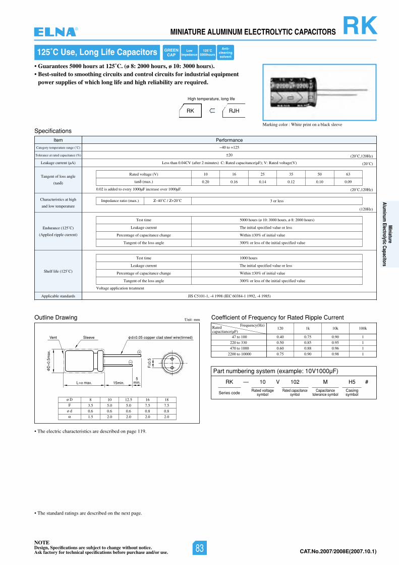
NOTEDesign, Specifications are subject to change without notice.Ask factory for technical specifications before purchase and/or use. CAT.No.2006/2007E(2006.10.1)
• The standard ratings are described on the next page.
RKMINIATURE ALUMINUM ELECTROLYTIC CAPACITORS
125˚C Use, Long Life Capacitors
• Guarantees 5000 hours at 125˚C. (ø 8: 2000 hours, ø 10: 3000 hours).• Best-suited to smoothing circuits and control circuits for industrial equipment
power supplies of which long life and high reliability are required.
RK RJH
High temperature, long life
Marking color : White print on a black sleeve
Outline Drawing Unit: mm
L max. 15min.5
min.
SleeveVent
D0.
5max
.
F0.
5
d 0.05 copper clad steel wire(tinned)
ø D
F
ø d
8 10 12.5 16
3.5 5.0 5.0 7.5
0.6 0.6 0.6 0.8
1.5 2.0 2.0 2.0
18
7.5
0.8
2.0
Coefficient of Frequency for Rated Ripple CurrentFrequency(Hz)
47 to 100
220 to 330
470 to 1000
2200 to 10000
120 1k 10k 100k
0.40 0.75 0.90 1
0.50 0.85 0.95 1
0.60 0.88 0.96 1
0.75 0.90 0.98 1
• The electric characteristics are described on page 119.
Specifications
Item Performance
Category temperature range (˚C)
Tolerance at rated capacitance (%)
Leakage current (µA)
Tangent of loss angle
(tan )
Characteristics at high
and low temperature
Endurance (125˚C)
(Applied ripple current)
Shelf life (125˚C)
)58914-,29911-48306CEI(89914-,1-1015CSIJsdradnatselbacilppA
40 to 125
20
Less than 0.04CV (after 2 minutes) C: Rated capacitance(µF); V: Rated voltage(V) (20˚C)
(20˚C,120Hz)
(20˚C,120Hz)
(120Hz)
Test time
Leakage current
Percentage of capacitance change
Tangent of the loss angle
Test time
Leakage current
Percentage of capacitance change
Tangent of the loss angle
1000 hours
The initial specified value or less
Within 30% of initial value
300% or less of the initial specified value
5000 hours (ø 10: 3000 hours, ø 8: 2000 hours)
The initial specified value or less
Within 30% of initial value
300% or less of the initial specified value
360553526101)V(egatlovdetaR
0.20 0.16 0.14 0.12 0.10 0.09tan (max.)
3 or lessImpedance ratio (max.) 40˚C / 20˚C
0.02 is added to every 1000µF increase over 1000µF.
Voltage application treatment
Ratedcapacitance(µF)
Part numbering system (example: 10V1000µF)
RK — V
Series code
10 102 M
Rated voltagesymbol
Rated capacitancesymbol
Capacitancetolerance symbol
H5
Casingsymbol
#
GREENCAP
LowImpedance
125˚C5000hours
Anti-cleaningsolvent
®
Miniature
Aluminum
Electrolytic Capacitors
NOTEDesign, Specifications are subject to change without notice.Ask factory for technical specifications before purchase and/or use. 83 CAT.No.2007/2008E(2007.10.1)
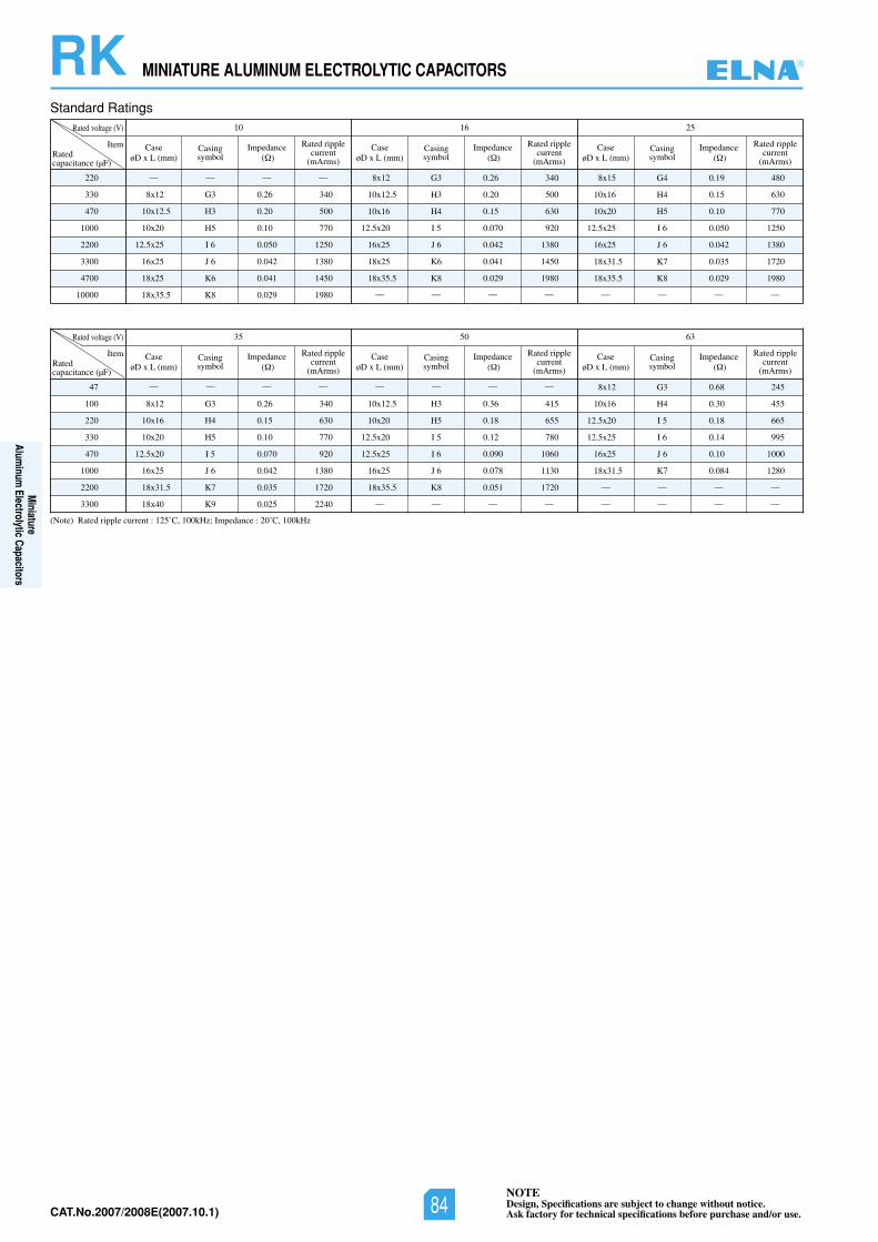
NOTEDesign, Specifications are subject to change without notice.Ask factory for technical specifications before purchase and/or use.CAT.No.2006/2007E(2006.10.1)
RK MINIATURE ALUMINUM ELECTROLYTIC CAPACITORS
Standard Ratings
220
330
470
1000
2200
3300
4700
10000
Rated voltage (V) 526110
Item
— — — —
8x12 G3 0.26 340
10x12.5 H3 0.20 500
10x20 H5 0.10 770
12.5x25 I 6 0.050 1250
16x25 J 6 0.042 1380
18x25 K6 0.041 1450
18x35.5 K8 0.029 1980
Ratedcapacitance (µF)
CaseøD x L (mm)
Casingsymbol
Rated ripplecurrent
(mArms)
Impedance( )
8x12 G3 0.26 340
10x12.5 H3 0.20 500
10x16 H4 0.15 630
12.5x20 I 5 0.070 920
16x25 J 6 0.042 1380
18x25 K6 0.041 1450
18x35.5 K8 0.029 1980
— — — —
CaseøD x L (mm)
Casingsymbol
Rated ripplecurrent
(mArms)
Impedance( )
8x15 G4 0.19 480
10x16 H4 0.15 630
10x20 H5 0.10 770
12.5x25 I 6 0.050 1250
16x25 J 6 0.042 1380
18x31.5 K7 0.035 1720
18x35.5 K8 0.029 1980
— — — —
CaseøD x L (mm)
Casingsymbol
Rated ripplecurrent
(mArms)
Impedance( )
(Note) Rated ripple current : 125˚C, 100kHz; Impedance : 20˚C, 100kHz
47
100
220
330
470
1000
2200
3300
Rated voltage (V) 360535
Item
— — — —
8x12 G3 0.26 340
10x16 H4 0.15 630
10x20 H5 0.10 770
12.5x20 I 5 0.070 920
16x25 J 6 0.042 1380
18x31.5 K7 0.035 1720
18x40 K9 0.025 2240
Ratedcapacitance (µF)
CaseøD x L (mm)
Casingsymbol
Rated ripplecurrent
(mArms)
Impedance( )
— — — —
10x12.5 H3 0.36 415
10x20 H5 0.18 655
12.5x20 I 5 0.12 780
12.5x25 I 6 0.090 1060
16x25 J 6 0.078 1130
18x35.5 K8 0.051 1720
— — — —
CaseøD x L (mm)
Casingsymbol
Rated ripplecurrent
(mArms)
Impedance( )
8x12 G3 0.68 245
10x16 H4 0.30 455
12.5x20 I 5 0.18 665
12.5x25 I 6 0.14 995
16x25 J 6 0.10 1000
18x31.5 K7 0.084 1280
— — — —
— — — —
CaseøD x L (mm)
Casingsymbol
Rated ripplecurrent
(mArms)
Impedance( )
®
Miniature
Aluminum
Electrolytic Capacitors
NOTEDesign, Specifications are subject to change without notice.Ask factory for technical specifications before purchase and/or use.84CAT.No.2007/2008E(2007.10.1)
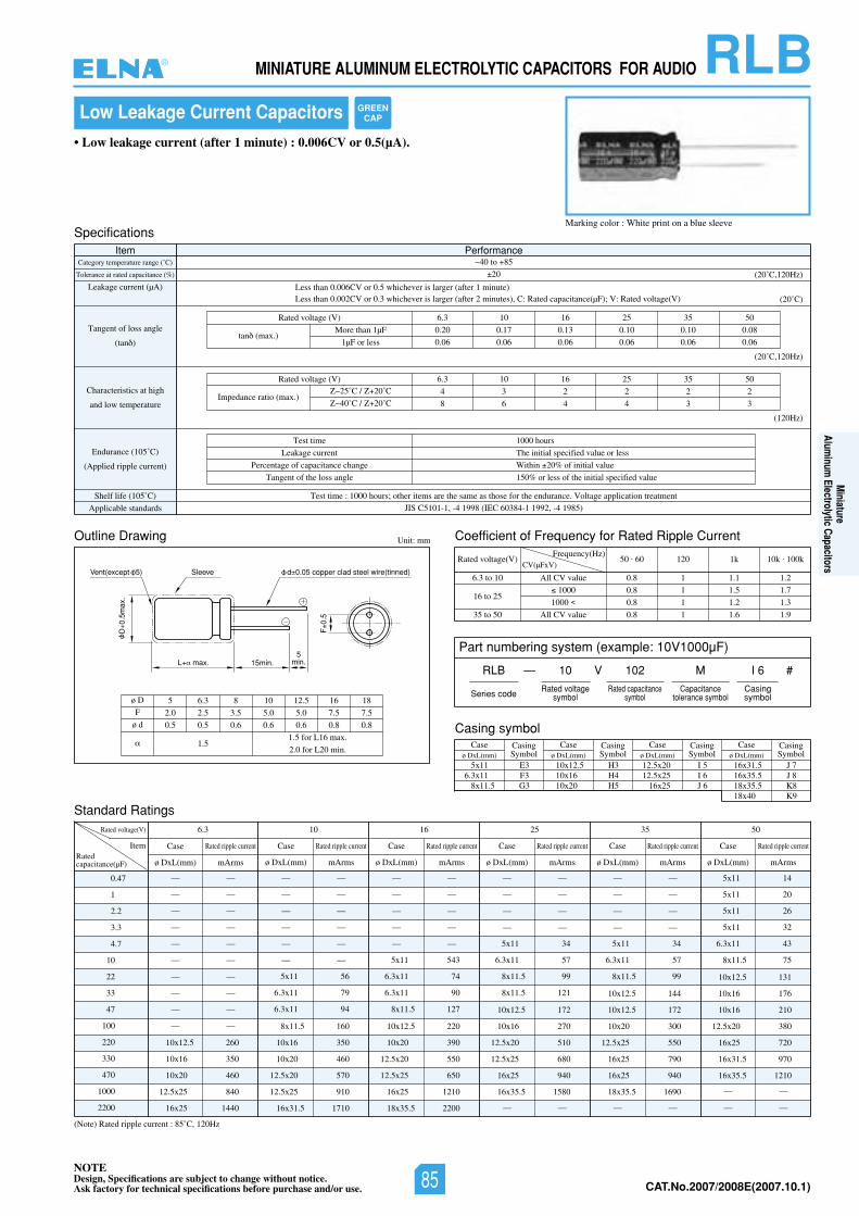
NOTEDesign, Specifications are subject to change without notice.Ask factory for technical specifications before purchase and/or use. CAT.No.2006/2007E(2006.10.1)
RLBMINIATURE ALUMINUM ELECTROLYTIC CAPACITORS FOR AUDIO
Outline Drawing Unit: mm
L max. 15min.5
min.
SleeveVent(except 5)
D0.
5max
.
F0.
5
d 0.05 copper clad steel wire(tinned)
ø D
F
ø d
5 6.3 8 10 12.5 16 18
2.0 2.5 3.5 5.0 5.0 7.5 7.5
0.5 0.5 0.6 0.6 0.6 0.8 0.8
1.51.5 for L16 max.
2.0 for L20 min.
Low Leakage Current Capacitors
• Low leakage current (after 1 minute) : 0.006CV or 0.5(µA).
Marking color : White print on a blue sleeve
Coefficient of Frequency for Rated Ripple Current
Rated voltage(V)Frequency(Hz)
6.3 to 10
16 to 25
35 to 50
All CV value
1000
1000
All CV value
50 . 60 120 1k 10k . 100k
0.8 1 1.1 1.2
0.8 1 1.5 1.7
0.8 1 1.2 1.3
0.8 1 1.6 1.9
CV(µFxV)
Standard Ratings
(Note) Rated ripple current : 85˚C, 120Hz
0.47
1
2.2
3.3
4.7
10
22
33
47
100
220
330
470
1000
2200
Rated voltage(V) 05535261013.6
ItemRatedcapacitance(µF)
— —
— —
— —
— —
— —
— —
— —
— —
— —
— —
10x12.5 260
10x16 350
10x20 460
12.5x25 840
16x25 1440
— —
— —
— —
— —
— —
— —
5x11 56
6.3x11 79
6.3x11 94
8x11.5 160
10x16 350
10x20 460
12.5x20 570
12.5x25 910
16x31.5 1710
— —
— —
— —
— —
— —
5x11 543
6.3x11 74
6.3x11 90
8x11.5 127
10x12.5 220
10x20 390
12.5x20 550
12.5x25 650
16x25 1210
18x35.5 2200
— —
— —
— —
— —
5x11 34
6.3x11 57
8x11.5 99
8x11.5 121
10x12.5 172
10x16 270
12.5x20 510
12.5x25 680
16x25 940
16x35.5 1580
— —
— —
— —
— —
— —
5x11 34
6.3x11 57
8x11.5 99
10x12.5 144
10x12.5 172
10x20 300
12.5x25 550
16x25 790
16x25 940
18x35.5 1690
— —
5x11 14
5x11 20
5x11 26
5x11 32
6.3x11 43
8x11.5 75
10x12.5 131
10x16 176
10x16 210
12.5x20 380
16x25 720
16x31.5 970
16x35.5 1210
— —
— —
Case
ø DxL(mm) mArms
Rated ripple current Case
ø DxL(mm) mArms
Rated ripple current Case
ø DxL(mm) mArms
Rated ripple current Case
ø DxL(mm) mArms
Rated ripple current Case
ø DxL(mm) mArms
Rated ripple current Case
ø DxL(mm) mArms
Rated ripple current
SpecificationsItem Performance
Category temperature range (˚C)
Tolerance at rated capacitance (%)
Leakage current (µA)
Tangent of loss angle
(tan )
Characteristics at high
and low temperature
Endurance (105˚C)
(Applied ripple current)
Shelf life (105˚ tnemtaertnoitacilppaegatloV.ecnarudneehtrofesohtsaemasehterasmetirehto;sruoh0001:emittseT)C
Applicable standards JIS C5101-1, -4 1998 (IEC 60384-1 1992, -4 1985)
40 to 85
20
Less than 0.006CV or 0.5 whichever is larger (after 1 minute)Less than 0.002CV or 0.3 whichever is larger (after 2 minutes), C: Rated capacitance(µF); V: Rated voltage(V) (20˚C)
(20˚C,120Hz)
Test time
Leakage current
Percentage of capacitance change
Tangent of the loss angle
1000 hours
The initial specified value or less
Within 20% of initial value
150% or less of the initial specified value
05535261013.6)V(egatlovdetaR
0.20 0.17 0.13 0.10 0.10 0.08
0.06 0.06 0.06 0.06 0.06 0.06tan (max.)
(20˚C,120Hz)
(120Hz)
05535261013.6)V(egatlovdetaR
4 3 2 2 2 2
8 6 4 4 3 3Impedance ratio (max.)
25˚C / 20˚C
40˚C / 20˚C
More than 1µF
1µF or less
Casing symbolCase
ø DxL(mm)CasingSymbol
Caseø DxL(mm)
CasingSymbol
Caseø DxL(mm)
CasingSymbol
Caseø DxL(mm)
CasingSymbol
5x11 E36.3x11 F3
8x11.5 G3
10x12.5 H310x16 H410x20 H5
16x31.5 J 716x35.5 J 818x35.5 K818x40 K9
12.5x20 I 512.5x25 I 6
16x25 J 6
Part numbering system (example: 10V1000µF)
RLB — V
Series code
10 102 M
Rated voltagesymbol
Rated capacitancesymbol
Capacitancetolerance symbol
I 6
Casingsymbol
#
GREENCAP
®
Miniature
Aluminum
Electrolytic Capacitors
NOTEDesign, Specifications are subject to change without notice.Ask factory for technical specifications before purchase and/or use. 85 CAT.No.2007/2008E(2007.10.1)
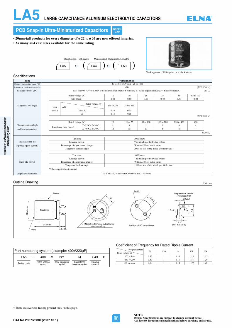
NOTEDesign, Specifications are subject to change without notice.Ask factory for technical specifications before purchase and/or use.CAT.No.2006/2007E(2006.10.1)
LA5 LARGE CAPACITANCE ALUMINUM ELECTROLYTIC CAPACITORS
There are overseas factory product only on this page.
L 2max.
D1m
ax.
Sleeve
Vent 4.0 0.5
Position of PC board holes(–)Negative terminal indicated by
cross notching
Lug terminal detailsThickness: 0.8t
(For 4.0 0.5) 2.1
0.9
1.5 0.1
0.9 0.1
5.4 4.7
100.1
10
2– 2
Markings
Outline Drawing
Coefficient of Frequency for Rated Ripple Current
Unit: mm
Rated voltage(V)
Frequency(Hz)
100 or less
160 to 250
315 or more
50 120 1k 10k 20k
0.95 1 1.10 1.15 1.15
0.87 1 1.11 1.18 1.20
0.80 1 1.14 1.19 1.20
PCB Snap-In Ultra-Miniaturized Capacitors
Marking color : White print on a black sleeve
• 20mm-tall products for every diameter of ø 22 to ø 35 are now offered in series.• As many as 4 case sizes available for the same rating.
LA4 LA3
Miniaturized, High ripple, Long lifeMiniaturized, High ripple
LA5
SpecificationsItem Performance
Category temperature range (˚C)
Tolerance at rated capacitance (%)
Leakage current (µA)
Tangent of loss angle
Characteristics at high
and low temperature
Endurance (85˚C)
(Applied ripple current)
Shelf life (85˚C)
Applicable standards JIS C5101-1, -4 1998 (IEC 60384-1 1992, -4 1985)
40 to 85(450V is at 25 to 85)
20
Less than 0.01CV or 1.5mA whichever is smaller(after 5 minutes) C: Rated capacitance(µF); V: Rated voltage(V)
001ot360553526101)V(egatlovdetaR
0.80 0.60 0.50 0.40 0.30 0.20
160 to 250 315 to 450
0.10 0.15
0.15 0.15
tan (max.)
(20˚C)
(20˚C,120Hz)
(20˚C,120Hz)
(120Hz)
Test time
Leakage current
Percentage of capacitance change
Tangent of the loss angle
2000 hours
The initial specified value or less
Within 20% of initial value
200% or less of the initial specified value
Test time
Leakage current
Percentage of capacitance change
Tangent of the loss angle
Voltage application treatment
1000 hours
The initial specified value or less
Within 15% of initial value
150% or less of the initial specified value
Rated voltage (V)
22 to 30
35
ø Dtan(max.)
054004ot052002ot061001ot0553ot6101)V(egatlovdetaR
5 4 3 3 4 4
18 15 10 6 8 —Impedance ratio (max.)
25˚C / 20˚C
40˚C / 20˚C
Part numbering system (example: 400V220µF)
LA5 — V
Series code
400 221 M
Rated voltagesymbol
Rated capacitancesymbol
Capacitancetolerance symbol
S43
Casingsymbol
#
GREENCAP
®
Large CapacitanceAlum
inum Electrolytic Capacitors
NOTEDesign, Specifications are subject to change without notice.Ask factory for technical specifications before purchase and/or use.86CAT.No.2007/2008E(2007.10.1)
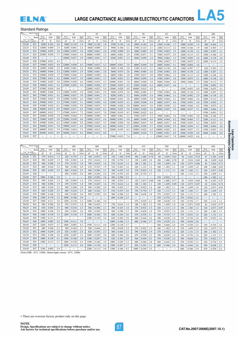
NOTEDesign, Specifications are subject to change without notice.Ask factory for technical specifications before purchase and/or use. CAT.No.2006/2007E(2006.10.1)
LA5LARGE CAPACITANCE ALUMINUM ELECTROLYTIC CAPACITORS
There are overseas factory product only on this page.
Standard Ratings
(Note) ESR : 20˚C, 120Hz ; Rated ripple current : 85˚C, 120Hz
22x20
22x25
22x30
22x35
22x40
22x45
22x50
25x20
25x25
25x30
25x35
25x40
25x45
25x50
30x20
30x25
30x30
30x35
30x40
30x45
30x50
35x20
35x25
35x30
35x35
35x40
35x45
35x50
S21
S22
S23
S24
S25
S26
S27
S31
S32
S33
S34
S35
S36
S37
S41
S42
S43
S44
S45
S46
S47
S51
S52
S53
S54
S55
S56
S57
Rated voltage(V) 10 16 25 35 50 63 80 100
ItemCase
ø DxL(mm)
8200 0.101 2.0
12000 0.069 2.5
15000 0.055 3.0
22000 0.038 3.7— — —
27000 0.031 4.3
33000 0.025 4.9
12000 0.069 2.5
18000 0.046 3.2
22000 0.038 3.7
27000 0.031 4.2
33000 0.025 4.8
39000 0.021 5.4
47000 0.018 6.0
18000 0.046 3.3
27000 0.031 4.2
33000 0.025 4.9
39000 0.021 5.5
47000 0.018 6.1
56000 0.015 6.9
68000 0.012 7.7
22000 0.038 3.9
33000 0.025 5.0
47000 0.018 6.2
56000 0.015 7.0
68000 0.012 7.9
82000 0.010 8.9— — —
5600 0.118 1.9
8200 0.081 2.4
12000 0.055 3.0
15000 0.044 3.4
18000 0.037 3.9— — —
22000 0.030 4.5
8200 0.081 2.4
12000 0.055 2.9
15000 0.044 3.4
18000 0.037 3.9
22000 0.030 4.4
27000 0.025 5.0— — —
12000 0.055 3.0
18000 0.037 3.9
22000 0.030 4.4
27000 0.025 5.1
33000 0.020 5.8
39000 0.017 6.4
47000 0.014 7.2
15000 0.044 3.7
22000 0.030 4.6
33000 0.020 5.8
39000 0.017 6.5
47000 0.014 7.4
56000 0.012 8.2— — —
3900 0.128 1.8
5600 0.089 2.3
8200 0.061 2.8
10000 0.050 3.2
12000 0.041 3.7— — —
15000 0.033 4.3
5600 0.089 2.2
8200 0.061 2.8
10000 0.050 3.2
12000 0.041 3.7
15000 0.033 4.2
18000 0.028 4.7
22000 0.023 5.4
8200 0.061 2.9
12000 0.041 3.7
15000 0.033 4.3
18000 0.028 4.8
22000 0.023 5.5
27000 0.018 6.2
33000 0.015 7.0
10000 0.050 3.5
15000 0.033 4.4
22000 0.023 5.5
27000 0.018 6.2
33000 0.015 7.2
39000 0.013 8.0— — —
2700 0.154 1.6
3900 0.106 2.1
4700 0.088 2.4
6800 0.061 2.9
8200 0.051 3.3— — —
10000 0.041 3.9
3900 0.106 2.0
5600 0.074 2.6
6800 0.061 2.9
8200 0.051 3.3
10000 0.041 3.8
12000 0.035 4.3
15000 0.028 4.9
5600 0.074 2.6
8200 0.051 3.3
10000 0.041 3.8
12000 0.035 4.3
15000 0.028 5.0
18000 0.023 5.6
22000 0.019 6.3
6800 0.061 3.1
10000 0.041 4.0
15000 0.028 5.0
18000 0.023 5.7
22000 0.019 6.4— — —
27000 0.015 7.4
1800 0.184 1.6
2700 0.123 2.1
3900 0.085 2.6
4700 0.071 3.1
5600 0.059 3.4— — —
6800 0.049 3.9
2700 0.123 2.1
3900 0.085 2.6
4700 0.071 3.0
5600 0.059 3.4
6800 0.049 3.8
8200 0.040 4.3
10000 0.033 4.9
3900 0.085 2.7
5600 0.059 3.4
6800 0.049 3.9
8200 0.040 4.4
10000 0.033 5.0
12000 0.028 5.6
15000 0.022 6.4
4700 0.071 3.2
6800 0.049 4.0
10000 0.033 5.0
12000 0.028 5.7
15000 0.022 6.5
18000 0.018 7.3— — —
1500 0.166 1.7
2200 0.113 2.2
2700 0.092 2.5
3300 0.075 2.9
3900 0.064 3.3
4700 0.053 3.7
5600 0.044 4.1
1800 0.138 2.0
2700 0.092 2.0
3900 0.064 3.2
4700 0.053 3.6
5600 0.044 4.0
6800 0.037 4.6— — —
2700 0.092 2.6
3900 0.064 3.3
5600 0.044 4.1
6800 0.037 4.6
8200 0.030 5.2
10000 0.025 5.9— — —
3900 0.064 3.4
5600 0.044 4.2
6800 0.037 4.8
8200 0.030 5.5
10000 0.025 6.2
12000 0.021 6.9
15000 0.017 7.9
1000 0.249 1.5
1500 0.166 1.9
1800 0.138 2.2
2200 0.113 2.5
2700 0.092 2.8
3300 0.075 3.2
3900 0.064 3.6
1200 0.207 1.7
1800 0.138 2.2
2200 0.113 2.5
3300 0.075 3.1
3900 0.064 3.5— — —
4700 0.053 4.0
1800 0.138 2.2
2700 0.092 2.9
3900 0.064 3.6
4700 0.053 4.0
5600 0.044 4.5
6800 0.037 5.1— — —
2700 0.092 3.0
3900 0.064 3.7
4700 0.053 4.2
5600 0.044 4.7
6800 0.037 5.3
8200 0.030 6.0
10000 0.025 6.8
560 0.444 1.3
820 0.303 1.7
1200 0.207 2.1
1500 0.166 2.5
1800 0.138 2.8
2200 0.113 3.2— — —
820 0.303 1.7
1200 0.207 2.1
1500 0.166 2.5
1800 0.138 2.8
2200 0.113 3.2
2700 0.092 2.9
3300 0.075 4.1
1200 0.207 2.2
1800 0.138 2.8
2200 0.113 3.2
2700 0.092 3.7
3300 0.075 4.2
3900 0.064 4.7
4700 0.053 5.2
1500 0.166 2.7
2200 0.113 3.4
3300 0.075 4.3
3900 0.064 4.8
4700 0.053 5.4
5600 0.044 6.0— — —
ESR
µF Arms
Ratedripplecurrent
Ratedcapacitance ESR
µF Arms
Ratedripplecurrent
Ratedcapacitance ESR
µF Arms
Ratedripplecurrent
Ratedcapacitance ESR
µF Arms
Ratedripplecurrent
Ratedcapacitance ESR
µF Arms
Ratedripplecurrent
Ratedcapacitance ESR
µF Arms
Ratedripplecurrent
Ratedcapacitance ESR
µF Arms
Ratedripplecurrent
Ratedcapacitance ESR
µF Arms
Ratedripplecurrent
Ratedcapacitance
Casingsymbol
22x20
22x25
22x30
22x35
22x40
22x45
22x50
25x20
25x25
25x30
25x35
25x40
25x45
25x50
30x20
30x25
30x30
30x35
30x40
30x45
30x50
35x20
35x25
35x30
35x35
35x40
35x45
35x50
S21
S22
S23
S24
S25
S26
S27
S31
S32
S33
S34
S35
S36
S37
S41
S42
S43
S44
S45
S46
S47
S51
S52
S53
S54
S55
S56
S57
Rated voltage(V) 160 180 200 250 315 350 400 450
ItemCase
ø DxL(mm)
270 0.614 1.2
390 0.425 1.5
560 0.296 1.9
680 0.244 2.2
820 0.202 2.5— — —
1000 0.166 2.9
390 0.425 1.5
560 0.296 1.9
680 0.244 2.2
820 0.202 2.5
1000 0.166 2.8
1200 0.138 3.2
1500 0.111 3.6
560 0.296 2.0
820 0.202 2.5
1000 0.166 2.9
1200 0.138 3.3
1500 0.111 3.7
1800 0.092 4.2
2200 0.075 4.7
680 0.366 2.3
1000 0.249 2.9
1500 0.166 3.6
1800 0.138 4.1
2200 0.113 4.7— — —
2700 0.092 5.4
220 0.754 1.1
330 0.503 1.4
470 0.353 1.8
560 0.296 2.0
680 0.244 2.3
820 0.202 2.6— — —
330 0.503 1.4
470 0.353 1.8
560 0.296 2.0
680 0.244 2.3
820 0.202 2.6
1000 0.166 2.9
1200 0.138 3.3
470 0.353 1.8
680 0.244 2.3
820 0.202 2.6
1200 0.138 3.3— — —
1500 0.111 3.9
1800 0.092 4.3
560 0.444 2.1
820 0.303 2.6
1200 0.207 3.3
1500 0.166 3.8
1800 0.138 4.3
2200 0.113 4.8— — —
180 0.922 1.0
270 0.614 1.3
390 0.425 1.6
470 0.353 1.9
560 0.296 2.1
680 0.244 2.4
820 0.202 2.6
270 0.614 1.3
390 0.425 1.6
560 0.296 2.0
680 0.244 2.3
820 0.202 2.6— — —
1000 0.166 3.0
390 0.425 1.7
560 0.296 2.1
820 0.202 2.7
1000 0.166 3.0
1200 0.138 3.4— — —
1500 0.111 4.0
560 0.444 2.1
820 0.303 2.7
1000 0.249 3.0
1200 0.207 3.4
1500 0.166 3.9
1800 0.138 4.4
2200 0.113 5.0
150 1.106 0.94
220 0.754 1.2
270 0.614 1.4
330 0.503 1.6
390 0.425 1.8
470 0.353 2.0
560 0.296 2.2
180 0.922 1.1
270 0.614 1.4
390 0.425 1.7
470 0.353 2.0
560 0.296 2.2
680 0.244 2.5— — —
270 0.614 1.4
390 0.425 1.8
560 0.296 2.3
680 0.244 2.6
820 0.202 2.9
1000 0.166 3.3
1200 0.138 3.7
390 0.638 1.8
560 0.444 2.3
680 0.366 2.6
820 0.303 2.9
1000 0.249 3.3
1200 0.207 3.7
1500 0.166 4.2
100 2.488 0.78
150 1.659 1.0
180 1.382 1.1
220 1.131 1.3
270 0.922 1.5
330 0.754 1.7— — —
120 2.073 0.88
180 1.382 1.1
270 0.922 1.4
330 0.754 1.7
390 0.638 1.8— — —
470 0.529 2.1
180 1.382 1.2
270 0.922 1.5
390 0.638 1.9
470 0.529 2.1
560 0.444 2.4
680 0.366 2.7— — —
270 0.922 1.5
390 0.638 1.9
470 0.529 2.2
560 0.444 2.5
680 0.366 2.8
820 0.303 3.1
1000 0.249 3.5
68 3.659 0.61
100 2.488 0.78
150 1.659 1.0
180 1.382 1.1
220 1.131 1.3— — —
270 0.922 1.5
100 2.488 0.77
150 1.659 0.99
180 1.382 1.1
220 1.131 1.3
270 0.922 1.5
330 0.754 1.7
390 0.638 1.9
150 1.659 1.0
220 1.131 1.3
270 0.922 1.5
330 0.754 1.7
390 0.638 1.9
470 0.529 2.1
560 0.444 2.4
180 1.382 1.2
270 0.922 1.6
390 0.638 1.9
470 0.529 2.2
560 0.444 2.5
680 0.366 2.8— — —
56 4.443 0.54
82 3.034 0.69
120 2.073 0.86
150 1.659 1.0
180 1.382 1.1
220 1.131 1.3— — —
82 3.034 0.69
120 2.073 0.87
150 1.659 1.0
180 1.382 1.1
220 1.131 1.3
270 0.922 1.5
330 0.754 1.7
120 2.073 0.93
180 1.382 1.2
220 1.131 1.4
270 0.922 1.6
330 0.754 1.8
390 0.638 2.0
470 0.529 2.2
150 1.659 1.2
220 1.131 1.5
330 0.754 1.8
390 0.638 2.1
470 0.529 2.3
560 0.444 2.6
680 0.366 2.9
47 5.294 0.49
68 3.659 0.62
82 3.034 0.71
100 2.488 0.82
120 2.073 0.92
150 1.659 1.1
180 1.382 1.2
56 4.443 0.57
82 3.034 0.72
120 2.073 0.91
150 1.659 1.0
180 1.382 1.2— — —
220 1.131 1.4
82 3.034 0.77
120 2.073 0.97
180 1.382 1.2
220 1.131 1.4
270 0.922 1.6— — —
330 0.754 1.8
120 2.073 1.0
180 1.382 1.3
220 1.131 1.5
270 0.922 1.7
330 0.754 1.9
390 0.638 2.2
470 0.529 2.4
ESR
µF Arms
Ratedripplecurrent
Ratedcapacitance ESR
µF Arms
Ratedripplecurrent
Ratedcapacitance ESR
µF Arms
Ratedripplecurrent
Ratedcapacitance ESR
µF Arms
Ratedripplecurrent
Ratedcapacitance ESR
µF Arms
Ratedripplecurrent
Ratedcapacitance ESR
µF Arms
Ratedripplecurrent
Ratedcapacitance ESR
µF Arms
Ratedripplecurrent
Ratedcapacitance ESR
µF Arms
Ratedripplecurrent
Ratedcapacitance
Casingsymbol
®
Large CapacitanceAlum
inum Electrolytic Capacitors
NOTEDesign, Specifications are subject to change without notice.Ask factory for technical specifications before purchase and/or use. 87 CAT.No.2007/2008E(2007.10.1)
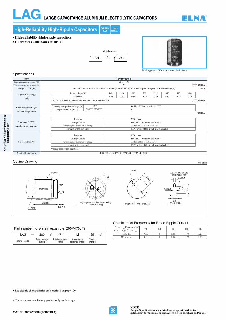
NOTEDesign, Specifications are subject to change without notice.Ask factory for technical specifications before purchase and/or use.CAT.No.2006/2007E(2006.10.1)
LAG LARGE CAPACITANCE ALUMINUM ELECTROLYTIC CAPACITORS
There are overseas factory product only on this page.
• The electric characteristics are described on page 120.
High-Reliability High-Ripple Capacitors
Marking color : White print on a black sleeve
• High-reliability, high-ripple capacitors.• Guarantees 2000 hours at 105˚C.
LAH LAG
Miniaturized
Unit: mm
SpecificationsItem Performance
Category temperature range (˚C)
Tolerance at rated capacitance (%)
Leakage current (µA)
Tangent of loss angle
(tan )
Characteristics at high
and low temperature
Endurance (105˚C)
(Applied ripple current)
Shelf life (105˚C)
Applicable standards JIS C5101-1, -4 1998 (IEC 60384-1 1992, -4 1985)
25 to 105
20
02()V(egatlovdetaR:V,)Fµ(ecnaticapacdetaR:C)setunim5retfa(rellamssirevehcihwAm3roVC20.0nahtsseL ˚C)
(20˚C,120Hz)
(20˚C,120Hz)
(120Hz)
Test time
Leakage current
Percentage of capacitance change
Tangent of the loss angle
2000 hours
The initial specified value or less
Within 20% of initial value
200% or less of the initial specified value
Test time
Leakage current
Percentage of capacitance change
Tangent of the loss angle
1000 hours
The initial specified value or less
Within 15% of initial value
150% or less of the initial specified value
Rated voltage (V) 160 180 200 250 315 350 385 400
0.10 0.10 0.10 0.15 0.15 0.15 0.15 0.15tan (max.)
0.15 for capacitors with ø35 and a WV equal to or less than 200
Voltage application treatment
Percentage of capacitance change (%) Within 30% of the value at 20˚C
4Impedance ratio (max.)
25˚C
25˚C / 20˚C
Outline Drawing
Coefficient of Frequency for Rated Ripple Current
Rated voltage(V)
Frequency(Hz)
160 to 250
315 or more
50 120 1k 10k 30k
0.87 1 1.11 1.18 1.20
0.80 1 1.14 1.19 1.20
L 2max.
D1m
ax.
Sleeve
Vent 4.0 0.5
Position of PC board holes(–)Negative terminal indicated by
cross notching
Lug terminal detailsThickness: 0.8t
(For 4.0 0.5) 2.1
0.9
1.5 0.1
0.9 0.1
5.4 4.7
100.1
10
2– 2
Markings
Part numbering system (example: 200V470µF)
LAG — V
Series code
200 471 M
Rated voltagesymbol
Rated capacitancesymbol
Capacitancetolerance symbol
S3
Casingsymbol
#
GREENCAP
105˚C2000hours
®
Large CapacitanceAlum
inum Electrolytic Capacitors
NOTEDesign, Specifications are subject to change without notice.Ask factory for technical specifications before purchase and/or use.88CAT.No.2007/2008E(2007.10.1)
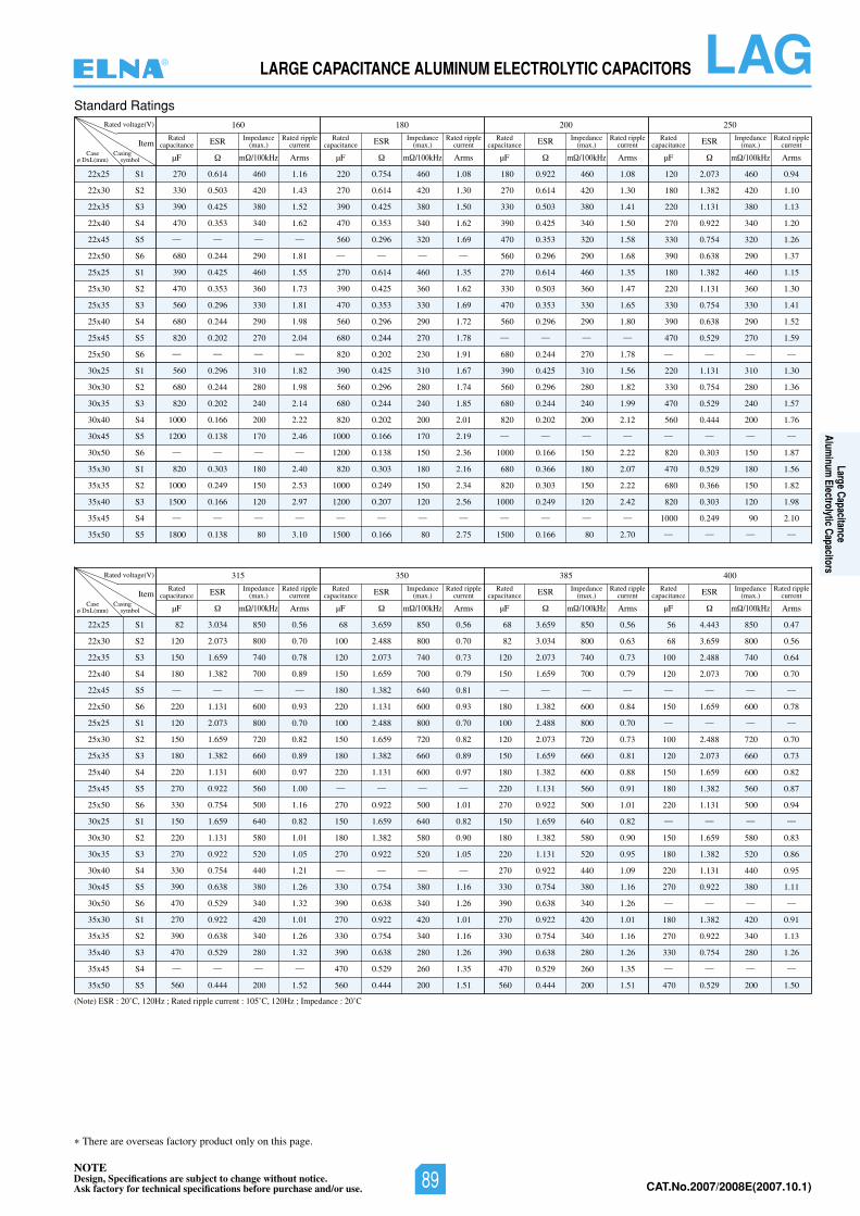
LAGLARGE CAPACITANCE ALUMINUM ELECTROLYTIC CAPACITORS
There are overseas factory product only on this page.
Standard Ratings
(Note) ESR : 20˚C, 120Hz ; Rated ripple current : 105˚C, 120Hz ; Impedance : 20˚C
22x25
22x30
22x35
22x40
22x45
22x50
25x25
25x30
25x35
25x40
25x45
25x50
30x25
30x30
30x35
30x40
30x45
30x50
35x30
35x35
35x40
35x45
35x50
S1
S2
S3
S4
S5
S6
S1
S2
S3
S4
S5
S6
S1
S2
S3
S4
S5
S6
S1
S2
S3
S4
S5
Rated voltage(V) 052002081061
ItemCase
ø DxL(mm)
270 0.614 460 1.16
330 0.503 420 1.43
390 0.425 380 1.52
470 0.353 340 1.62
— — — —
680 0.244 290 1.81
390 0.425 460 1.55
470 0.353 360 1.73
560 0.296 330 1.81
680 0.244 290 1.98
820 0.202 270 2.04
— — — —
560 0.296 310 1.82
680 0.244 280 1.98
820 0.202 240 2.14
1000 0.166 200 2.22
1200 0.138 170 2.46
— — — —
820 0.303 180 2.40
1000 0.249 150 2.53
1500 0.166 120 2.97
— — — —
1800 0.138 80 3.10
220 0.754 460 1.08
270 0.614 420 1.30
390 0.425 380 1.50
470 0.353 340 1.62
560 0.296 320 1.69
— — — —
270 0.614 460 1.35
390 0.425 360 1.62
470 0.353 330 1.69
560 0.296 290 1.72
680 0.244 270 1.78
820 0.202 230 1.91
390 0.425 310 1.67
560 0.296 280 1.74
680 0.244 240 1.85
820 0.202 200 2.01
1000 0.166 170 2.19
1200 0.138 150 2.36
820 0.303 180 2.16
1000 0.249 150 2.34
1200 0.207 120 2.56
— — — —
1500 0.166 80 2.75
180 0.922 460 1.08
270 0.614 420 1.30
330 0.503 380 1.41
390 0.425 340 1.50
470 0.353 320 1.58
560 0.296 290 1.68
270 0.614 460 1.35
330 0.503 360 1.47
470 0.353 330 1.65
560 0.296 290 1.80
— — — —
680 0.244 270 1.78
390 0.425 310 1.56
560 0.296 280 1.82
680 0.244 240 1.99
820 0.202 200 2.12
— — — —
1000 0.166 150 2.22
680 0.366 180 2.07
820 0.303 150 2.22
1000 0.249 120 2.42
— — — —
1500 0.166 80 2.70
120 2.073 460 0.94
180 1.382 420 1.10
220 1.131 380 1.13
270 0.922 340 1.20
330 0.754 320 1.26
390 0.638 290 1.37
180 1.382 460 1.15
220 1.131 360 1.30
330 0.754 330 1.41
390 0.638 290 1.52
470 0.529 270 1.59
— — — —
220 1.131 310 1.30
330 0.754 280 1.36
470 0.529 240 1.57
560 0.444 200 1.76
— — — —
820 0.303 150 1.87
470 0.529 180 1.56
680 0.366 150 1.82
820 0.303 120 1.98
1000 0.249 90 2.10
— — — —
ESR
µF m /100kHz Arms
Ratedcapacitance
Rated ripplecurrent
Impedance(max.) ESR
µF m /100kHz Arms
Ratedcapacitance
Rated ripplecurrent
Impedance(max.) ESR
µF m /100kHz Arms
Ratedcapacitance
Rated ripplecurrent
Impedance(max.) ESR
µF m /100kHz Arms
Ratedcapacitance
Rated ripplecurrent
Impedance(max.)
Casingsymbol
22x25
22x30
22x35
22x40
22x45
22x50
25x25
25x30
25x35
25x40
25x45
25x50
30x25
30x30
30x35
30x40
30x45
30x50
35x30
35x35
35x40
35x45
35x50
S1
S2
S3
S4
S5
S6
S1
S2
S3
S4
S5
S6
S1
S2
S3
S4
S5
S6
S1
S2
S3
S4
S5
Rated voltage(V) 004583053513
ItemCase
ø DxL(mm)
82 3.034 850 0.56
120 2.073 800 0.70
150 1.659 740 0.78
180 1.382 700 0.89
— — — —
220 1.131 600 0.93
120 2.073 800 0.70
150 1.659 720 0.82
180 1.382 660 0.89
220 1.131 600 0.97
270 0.922 560 1.00
330 0.754 500 1.16
150 1.659 640 0.82
220 1.131 580 1.01
270 0.922 520 1.05
330 0.754 440 1.21
390 0.638 380 1.26
470 0.529 340 1.32
270 0.922 420 1.01
390 0.638 340 1.26
470 0.529 280 1.32
— — — —
560 0.444 200 1.52
68 3.659 850 0.56
100 2.488 800 0.70
120 2.073 740 0.73
150 1.659 700 0.79
180 1.382 640 0.81
220 1.131 600 0.93
100 2.488 800 0.70
150 1.659 720 0.82
180 1.382 660 0.89
220 1.131 600 0.97
— — — —
270 0.922 500 1.01
150 1.659 640 0.82
180 1.382 580 0.90
270 0.922 520 1.05
— — — —
330 0.754 380 1.16
390 0.638 340 1.26
270 0.922 420 1.01
330 0.754 340 1.16
390 0.638 280 1.26
470 0.529 260 1.35
560 0.444 200 1.51
68 3.659 850 0.56
82 3.034 800 0.63
120 2.073 740 0.73
150 1.659 700 0.79
— — — —
180 1.382 600 0.84
100 2.488 800 0.70
120 2.073 720 0.73
150 1.659 660 0.81
180 1.382 600 0.88
220 1.131 560 0.91
270 0.922 500 1.01
150 1.659 640 0.82
180 1.382 580 0.90
220 1.131 520 0.95
270 0.922 440 1.09
330 0.754 380 1.16
390 0.638 340 1.26
270 0.922 420 1.01
330 0.754 340 1.16
390 0.638 280 1.26
470 0.529 260 1.35
560 0.444 200 1.51
56 4.443 850 0.47
68 3.659 800 0.56
100 2.488 740 0.64
120 2.073 700 0.70
— — — —
150 1.659 600 0.78
— — — —
100 2.488 720 0.70
120 2.073 660 0.73
150 1.659 600 0.82
180 1.382 560 0.87
220 1.131 500 0.94
— — — —
150 1.659 580 0.83
180 1.382 520 0.86
220 1.131 440 0.95
270 0.922 380 1.11
— — — —
180 1.382 420 0.91
270 0.922 340 1.13
330 0.754 280 1.26
— — — —
470 0.529 200 1.50
ESR
µF m /100kHz Arms
Ratedcapacitance
Rated ripplecurrent
Impedance(max.) ESR
µF m /100kHz Arms
Ratedcapacitance
Rated ripplecurrent
Impedance(max.) ESR
µF m /100kHz Arms
Ratedcapacitance
Rated ripplecurrent
Impedance(max.) ESR
µF m /100kHz Arms
Ratedcapacitance
Rated ripplecurrent
Impedance(max.)
Casingsymbol
NOTEDesign, Specifications are subject to change without notice.Ask factory for technical specifications before purchase and/or use. CAT.No.2006/2007E(2006.10.1)
®
Large CapacitanceAlum
inum Electrolytic Capacitors
NOTEDesign, Specifications are subject to change without notice.Ask factory for technical specifications before purchase and/or use. 89 CAT.No.2007/2008E(2007.10.1)
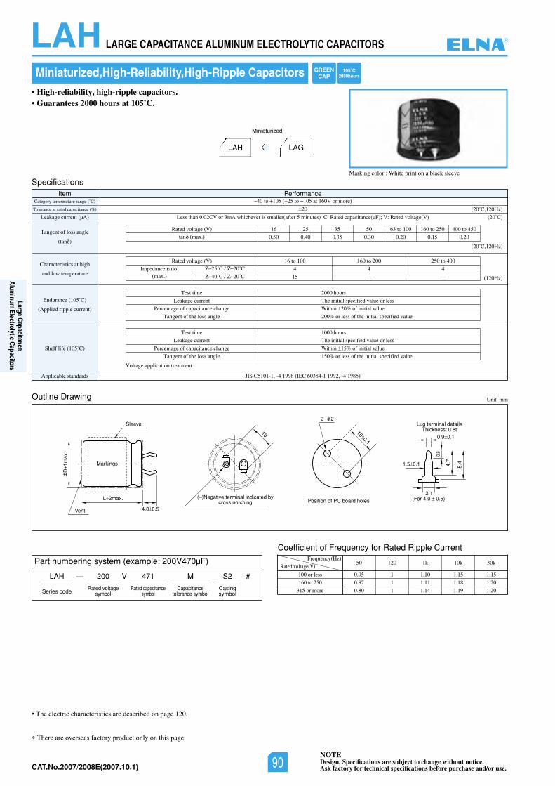
NOTEDesign, Specifications are subject to change without notice.Ask factory for technical specifications before purchase and/or use.CAT.No.2006/2007E(2006.10.1)
LAH LARGE CAPACITANCE ALUMINUM ELECTROLYTIC CAPACITORS
There are overseas factory product only on this page.
Miniaturized,High-Reliability,High-Ripple Capacitors
Marking color : White print on a black sleeve
• High-reliability, high-ripple capacitors.• Guarantees 2000 hours at 105˚C.
LAH LAG
Miniaturized
Unit: mm
SpecificationsItem Performance
Category temperature range (˚C)
Tolerance at rated capacitance (%)
Leakage current (µA)
Tangent of loss angle
(tan )
Characteristics at high
and low temperature
Endurance (105˚C)
(Applied ripple current)
Shelf life (105˚C)
Applicable standards JIS C5101-1, -4 1998 (IEC 60384-1 1992, -4 1985)
40 to 105 ( 25 to 105 at 160V or more)
20
02()V(egatlovdetaR:V;)Fµ(ecnaticapacdetaR:C)setunim5retfa(rellamssirevehcihwAm3roVC20.0nahtsseL ˚C)
(20˚C,120Hz)
(20˚C,120Hz)
(120Hz)
Test time
Leakage current
Percentage of capacitance change
Tangent of the loss angle
2000 hours
The initial specified value or less
Within 20% of initial value
200% or less of the initial specified value
Test time
Leakage current
Percentage of capacitance change
Tangent of the loss angle
1000 hours
The initial specified value or less
Within 15% of initial value
150% or less of the initial specified value
054ot004052ot061001ot3605535261)V(egatlovdetaR
0.50 0.40 0.35 0.30 0.20 0.15 0.20tan (max.)
Voltage application treatment
Outline Drawing
Coefficient of Frequency for Rated Ripple Current
Rated voltage(V)
Frequency(Hz)
100 or less
160 to 250
315 or more
50 120 1k 10k 30k
0.95 1 1.10 1.15 1.15
0.87 1 1.11 1.18 1.20
0.80 1 1.14 1.19 1.20
004ot052002ot061001ot61)V(egatlovdetaR
444
15 ——Impedance ratio
(max.)25˚C / 20˚C
40˚C / 20˚C
L 2max.
D1m
ax.
Sleeve
Vent 4.0 0.5
Position of PC board holes(–)Negative terminal indicated by
cross notching
Lug terminal detailsThickness: 0.8t
(For 4.0 0.5) 2.1
0.9
1.5 0.1
0.9 0.1
5.4 4.7
100.1
10
2– 2
Markings
• The electric characteristics are described on page 120.
Part numbering system (example: 200V470µF)
LAH — V
Series code
200 471 M
Rated voltagesymbol
Rated capacitancesymbol
Capacitancetolerance symbol
S2
Casingsymbol
#
GREENCAP
105˚C2000hours
®
Large CapacitanceAlum
inum Electrolytic Capacitors
NOTEDesign, Specifications are subject to change without notice.Ask factory for technical specifications before purchase and/or use.90CAT.No.2007/2008E(2007.10.1)
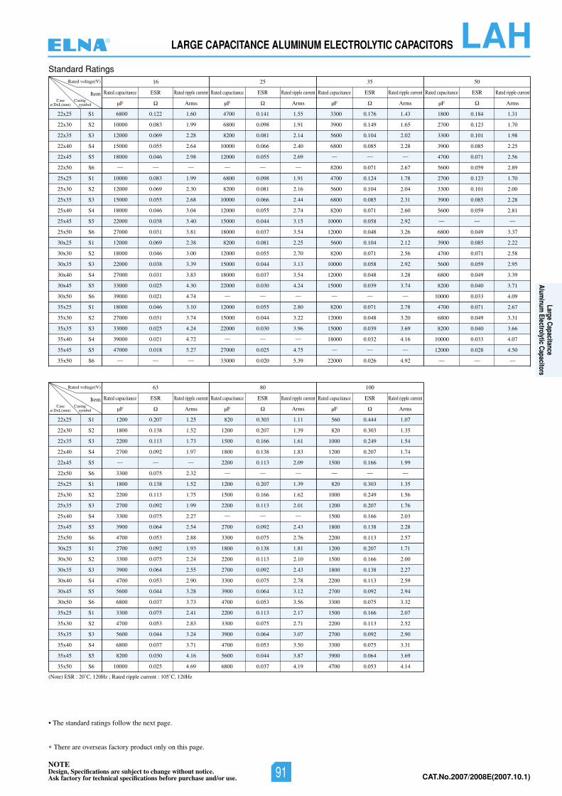
NOTEDesign, Specifications are subject to change without notice.Ask factory for technical specifications before purchase and/or use. CAT.No.2006/2007E(2006.10.1)
LAHLARGE CAPACITANCE ALUMINUM ELECTROLYTIC CAPACITORS
There are overseas factory product only on this page.
Standard Ratings
(Note) ESR : 20˚C, 120Hz ; Rated ripple current : 105˚C, 120Hz
22x25
22x30
22x35
22x40
22x45
22x50
25x25
25x30
25x35
25x40
25x45
25x50
30x25
30x30
30x35
30x40
30x45
30x50
35x25
35x30
35x35
35x40
35x45
35x50
S1
S2
S3
S4
S5
S6
S1
S2
S3
S4
S5
S6
S1
S2
S3
S4
S5
S6
S1
S2
S3
S4
S5
S6
Rated voltage(V) 05535261
ItemCase
ø DxL(mm)
6800 0.122 1.60
10000 0.083 1.99
12000 0.069 2.28
15000 0.055 2.64
18000 0.046 2.98
— — —
10000 0.083 1.99
12000 0.069 2.30
15000 0.055 2.68
18000 0.046 3.04
22000 0.038 3.40
27000 0.031 3.81
12000 0.069 2.38
18000 0.046 3.00
22000 0.038 3.39
27000 0.031 3.83
33000 0.025 4.30
39000 0.021 4.74
18000 0.046 3.10
27000 0.031 3.74
33000 0.025 4.24
39000 0.021 4.72
47000 0.018 5.27
— — —
4700 0.141 1.55
6800 0.098 1.91
8200 0.081 2.14
10000 0.066 2.40
12000 0.055 2.69
— — —
6800 0.098 1.91
8200 0.081 2.16
10000 0.066 2.44
12000 0.055 2.74
15000 0.044 3.15
18000 0.037 3.54
8200 0.081 2.25
12000 0.055 2.70
15000 0.044 3.13
18000 0.037 3.54
22000 0.030 4.24
— — —
12000 0.055 2.80
15000 0.044 3.22
22000 0.030 3.96
— — —
27000 0.025 4.75
33000 0.020 5.39
3300 0.176 1.43
3900 0.149 1.65
5600 0.104 2.02
6800 0.085 2.28
— — —
8200 0.071 2.67
4700 0.124 1.78
5600 0.104 2.04
6800 0.085 2.31
8200 0.071 2.60
10000 0.058 2.92
12000 0.048 3.26
5600 0.104 2.12
8200 0.071 2.56
10000 0.058 2.92
12000 0.048 3.28
15000 0.039 3.74
— — —
8200 0.071 2.78
12000 0.048 3.20
15000 0.039 3.69
18000 0.032 4.16
— — —
22000 0.026 4.92
1800 0.184 1.31
2700 0.123 1.70
3300 0.101 1.98
3900 0.085 2.25
4700 0.071 2.56
5600 0.059 2.89
2700 0.123 1.70
3300 0.101 2.00
3900 0.085 2.28
5600 0.059 2.81
— — —
6800 0.049 3.37
3900 0.085 2.22
4700 0.071 2.58
5600 0.059 2.95
6800 0.049 3.39
8200 0.040 3.71
10000 0.033 4.09
4700 0.071 2.67
6800 0.049 3.31
8200 0.040 3.66
10000 0.033 4.07
12000 0.028 4.50
— — —
ESR
µF ArmsCasing
symbol
Rated capacitance Rated ripple current ESR
µF Arms
Rated capacitance Rated ripple current ESR
µF Arms
Rated capacitance Rated ripple current ESR
µF Arms
Rated capacitance Rated ripple current
22x25
22x30
22x35
22x40
22x45
22x50
25x25
25x30
25x35
25x40
25x45
25x50
30x25
30x30
30x35
30x40
30x45
30x50
35x25
35x30
35x35
35x40
35x45
35x50
S1
S2
S3
S4
S5
S6
S1
S2
S3
S4
S5
S6
S1
S2
S3
S4
S5
S6
S1
S2
S3
S4
S5
S6
Rated voltage(V) 0010836
ItemCase
ø DxL(mm)
1200 0.207 1.25
1800 0.138 1.52
2200 0.113 1.73
2700 0.092 1.97
— — —
3300 0.075 2.32
1800 0.138 1.52
2200 0.113 1.75
2700 0.092 1.99
3300 0.075 2.27
3900 0.064 2.54
4700 0.053 2.88
2700 0.092 1.93
3300 0.075 2.24
3900 0.064 2.55
4700 0.053 2.90
5600 0.044 3.28
6800 0.037 3.73
3300 0.075 2.41
4700 0.053 2.83
5600 0.044 3.24
6800 0.037 3.71
8200 0.030 4.16
10000 0.025 4.69
820 0.303 1.11
1200 0.207 1.39
1500 0.166 1.61
1800 0.138 1.83
2200 0.113 2.09
— — —
1200 0.207 1.39
1500 0.166 1.62
2200 0.113 2.01
— — —
2700 0.092 2.43
3300 0.075 2.76
1800 0.138 1.81
2200 0.113 2.10
2700 0.092 2.43
3300 0.075 2.78
3900 0.064 3.12
4700 0.053 3.56
2200 0.113 2.17
3300 0.075 2.71
3900 0.064 3.07
4700 0.053 3.50
5600 0.044 3.87
6800 0.037 4.19
560 0.444 1.07
820 0.303 1.35
1000 0.249 1.54
1200 0.207 1.74
1500 0.166 1.99
— — —
820 0.303 1.35
1000 0.249 1.56
1200 0.207 1.76
1500 0.166 2.03
1800 0.138 2.28
2200 0.113 2.57
1200 0.207 1.71
1500 0.166 2.00
1800 0.138 2.27
2200 0.113 2.59
2700 0.092 2.94
3300 0.075 3.32
1500 0.166 2.07
2200 0.113 2.52
2700 0.092 2.90
3300 0.075 3.31
3900 0.064 3.69
4700 0.053 4.14
ESR
µF ArmsCasing
symbol
Rated capacitance Rated ripple current ESR
µF Arms
Rated capacitance Rated ripple current ESR
µF Arms
Rated capacitance Rated ripple current
• The standard ratings follow the next page.
®
Large CapacitanceAlum
inum Electrolytic Capacitors
NOTEDesign, Specifications are subject to change without notice.Ask factory for technical specifications before purchase and/or use. 91 CAT.No.2007/2008E(2007.10.1)
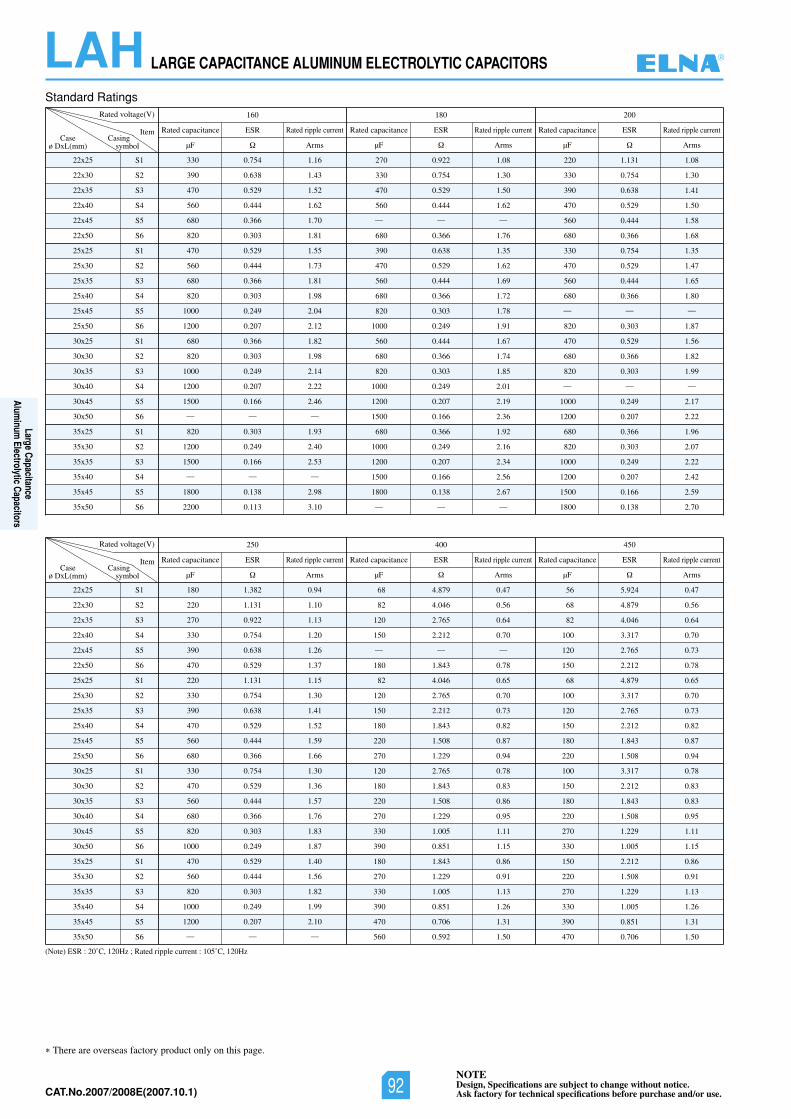
NOTEDesign, Specifications are subject to change without notice.Ask factory for technical specifications before purchase and/or use.CAT.No.2006/2007E(2006.10.1)
LAH LARGE CAPACITANCE ALUMINUM ELECTROLYTIC CAPACITORS
There are overseas factory product only on this page.
Standard Ratings
(Note) ESR : 20˚C, 120Hz ; Rated ripple current : 105˚C, 120Hz
22x25
22x30
22x35
22x40
22x45
22x50
25x25
25x30
25x35
25x40
25x45
25x50
30x25
30x30
30x35
30x40
30x45
30x50
35x25
35x30
35x35
35x40
35x45
35x50
S1
S2
S3
S4
S5
S6
S1
S2
S3
S4
S5
S6
S1
S2
S3
S4
S5
S6
S1
S2
S3
S4
S5
S6
Rated voltage(V) 002081061
ItemCase
ø DxL(mm)
330 0.754 1.16
390 0.638 1.43
470 0.529 1.52
560 0.444 1.62
680 0.366 1.70
820 0.303 1.81
470 0.529 1.55
560 0.444 1.73
680 0.366 1.81
820 0.303 1.98
1000 0.249 2.04
1200 0.207 2.12
680 0.366 1.82
820 0.303 1.98
1000 0.249 2.14
1200 0.207 2.22
1500 0.166 2.46
— — —
820 0.303 1.93
1200 0.249 2.40
1500 0.166 2.53
— — —
1800 0.138 2.98
2200 0.113 3.10
270 0.922 1.08
330 0.754 1.30
470 0.529 1.50
560 0.444 1.62
— — —
680 0.366 1.76
390 0.638 1.35
470 0.529 1.62
560 0.444 1.69
680 0.366 1.72
820 0.303 1.78
1000 0.249 1.91
560 0.444 1.67
680 0.366 1.74
820 0.303 1.85
1000 0.249 2.01
1200 0.207 2.19
1500 0.166 2.36
680 0.366 1.92
1000 0.249 2.16
1200 0.207 2.34
1500 0.166 2.56
1800 0.138 2.67
— — —
220 1.131 1.08
330 0.754 1.30
390 0.638 1.41
470 0.529 1.50
560 0.444 1.58
680 0.366 1.68
330 0.754 1.35
470 0.529 1.47
560 0.444 1.65
680 0.366 1.80
— — —
820 0.303 1.87
470 0.529 1.56
680 0.366 1.82
820 0.303 1.99
— — —
1000 0.249 2.17
1200 0.207 2.22
680 0.366 1.96
820 0.303 2.07
1000 0.249 2.22
1200 0.207 2.42
1500 0.166 2.59
1800 0.138 2.70
ESR
µF ArmsCasing
symbol
Rated capacitance Rated ripple current ESR
µF Arms
Rated capacitance Rated ripple current ESR
µF Arms
Rated capacitance Rated ripple current
22x25
22x30
22x35
22x40
22x45
22x50
25x25
25x30
25x35
25x40
25x45
25x50
30x25
30x30
30x35
30x40
30x45
30x50
35x25
35x30
35x35
35x40
35x45
35x50
S1
S2
S3
S4
S5
S6
S1
S2
S3
S4
S5
S6
S1
S2
S3
S4
S5
S6
S1
S2
S3
S4
S5
S6
Rated voltage(V) 054004052
ItemCase
ø DxL(mm)
180 1.382 0.94
220 1.131 1.10
270 0.922 1.13
330 0.754 1.20
390 0.638 1.26
470 0.529 1.37
220 1.131 1.15
330 0.754 1.30
390 0.638 1.41
470 0.529 1.52
560 0.444 1.59
680 0.366 1.66
330 0.754 1.30
470 0.529 1.36
560 0.444 1.57
680 0.366 1.76
820 0.303 1.83
1000 0.249 1.87
470 0.529 1.40
560 0.444 1.56
820 0.303 1.82
1000 0.249 1.99
1200 0.207 2.10
— — —
68 4.879 0.47
82 4.046 0.56
120 2.765 0.64
150 2.212 0.70
— — —
180 1.843 0.78
82 4.046 0.65
120 2.765 0.70
150 2.212 0.73
180 1.843 0.82
220 1.508 0.87
270 1.229 0.94
120 2.765 0.78
180 1.843 0.83
220 1.508 0.86
270 1.229 0.95
330 1.005 1.11
390 0.851 1.15
180 1.843 0.86
270 1.229 0.91
330 1.005 1.13
390 0.851 1.26
470 0.706 1.31
560 0.592 1.50
56 5.924 0.47
68 4.879 0.56
82 4.046 0.64
100 3.317 0.70
120 2.765 0.73
150 2.212 0.78
68 4.879 0.65
100 3.317 0.70
120 2.765 0.73
150 2.212 0.82
180 1.843 0.87
220 1.508 0.94
100 3.317 0.78
150 2.212 0.83
180 1.843 0.83
220 1.508 0.95
270 1.229 1.11
330 1.005 1.15
150 2.212 0.86
220 1.508 0.91
270 1.229 1.13
330 1.005 1.26
390 0.851 1.31
470 0.706 1.50
ESR
µF ArmsCasing
symbol
Rated capacitance Rated ripple current ESR
µF Arms
Rated capacitance Rated ripple current ESR
µF Arms
Rated capacitance Rated ripple current
®
Large CapacitanceAlum
inum Electrolytic Capacitors
NOTEDesign, Specifications are subject to change without notice.Ask factory for technical specifications before purchase and/or use.92CAT.No.2007/2008E(2007.10.1)
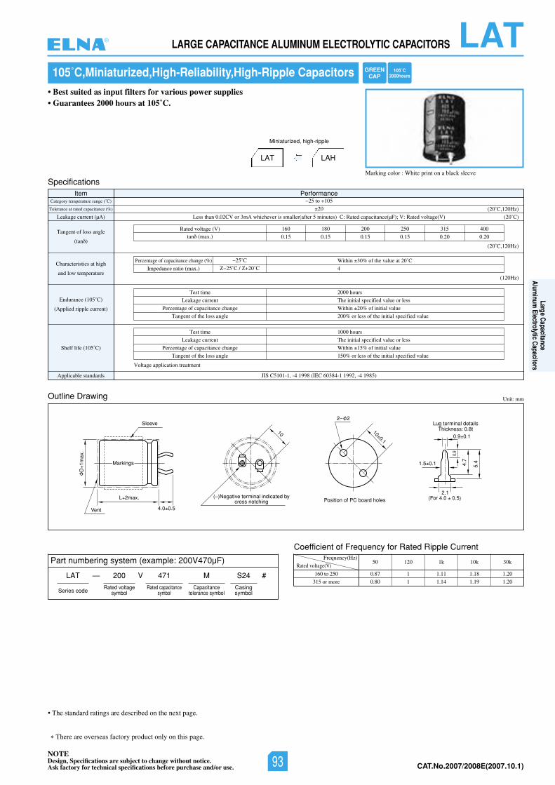
NOTEDesign, Specifications are subject to change without notice.Ask factory for technical specifications before purchase and/or use. CAT.No.2006/2007E(2006.10.1)
LATLARGE CAPACITANCE ALUMINUM ELECTROLYTIC CAPACITORS
There are overseas factory product only on this page.
105˚C,Miniaturized,High-Reliability,High-Ripple Capacitors
Marking color : White print on a black sleeve
• Best suited as input filters for various power supplies• Guarantees 2000 hours at 105˚C.
LAT LAH
Miniaturized, high-ripple
Unit: mm
SpecificationsItem Performance
Category temperature range (˚C)
Tolerance at rated capacitance (%)
Leakage current (µA)
Tangent of loss angle
(tan )
Characteristics at high
and low temperature
Endurance (105˚C)
(Applied ripple current)
Shelf life (105˚C)
Applicable standards JIS C5101-1, -4 1998 (IEC 60384-1 1992, -4 1985)
25 to 105
20
02()V(egatlovdetaR:V;)Fµ(ecnaticapacdetaR:C)setunim5retfa(rellamssirevehcihwAm3roVC20.0nahtsseL ˚C)
(20˚C,120Hz)
(20˚C,120Hz)
(120Hz)
Test time
Leakage current
Percentage of capacitance change
Tangent of the loss angle
2000 hours
The initial specified value or less
Within 20% of initial value
200% or less of the initial specified value
Test time
Leakage current
Percentage of capacitance change
Tangent of the loss angle
1000 hours
The initial specified value or less
Within 15% of initial value
150% or less of the initial specified value
004513052002081061)V(egatlovdetaR
0.15 0.15 0.15 0.15 0.20 0.20tan (max.)
Voltage application treatment
Percentage of capacitance change (%) Within 30% of the value at 20˚C
4Impedance ratio (max.)
25˚C
25˚C / 20˚C
Outline Drawing
Coefficient of Frequency for Rated Ripple Current
Rated voltage(V)
Frequency(Hz)
160 to 250
315 or more
50 120 1k 10k 30k
0.87 1 1.11 1.18 1.20
0.80 1 1.14 1.19 1.20
L 2max.
D1m
ax.
Sleeve
Vent 4.0 0.5
Position of PC board holes(–)Negative terminal indicated by
cross notching
Lug terminal detailsThickness: 0.8t
(For 4.0 0.5) 2.1
0.9
1.5 0.1
0.9 0.1
5.4 4.7
100.1
10
2– 2
Markings
• The standard ratings are described on the next page.
Part numbering system (example: 200V470µF)
LAT — V
Series code
200 471 M
Rated voltagesymbol
Rated capacitancesymbol
Capacitancetolerance symbol
S24
Casingsymbol
#
GREENCAP
105˚C2000hours
®
Large CapacitanceAlum
inum Electrolytic Capacitors
NOTEDesign, Specifications are subject to change without notice.Ask factory for technical specifications before purchase and/or use. 93 CAT.No.2007/2008E(2007.10.1)
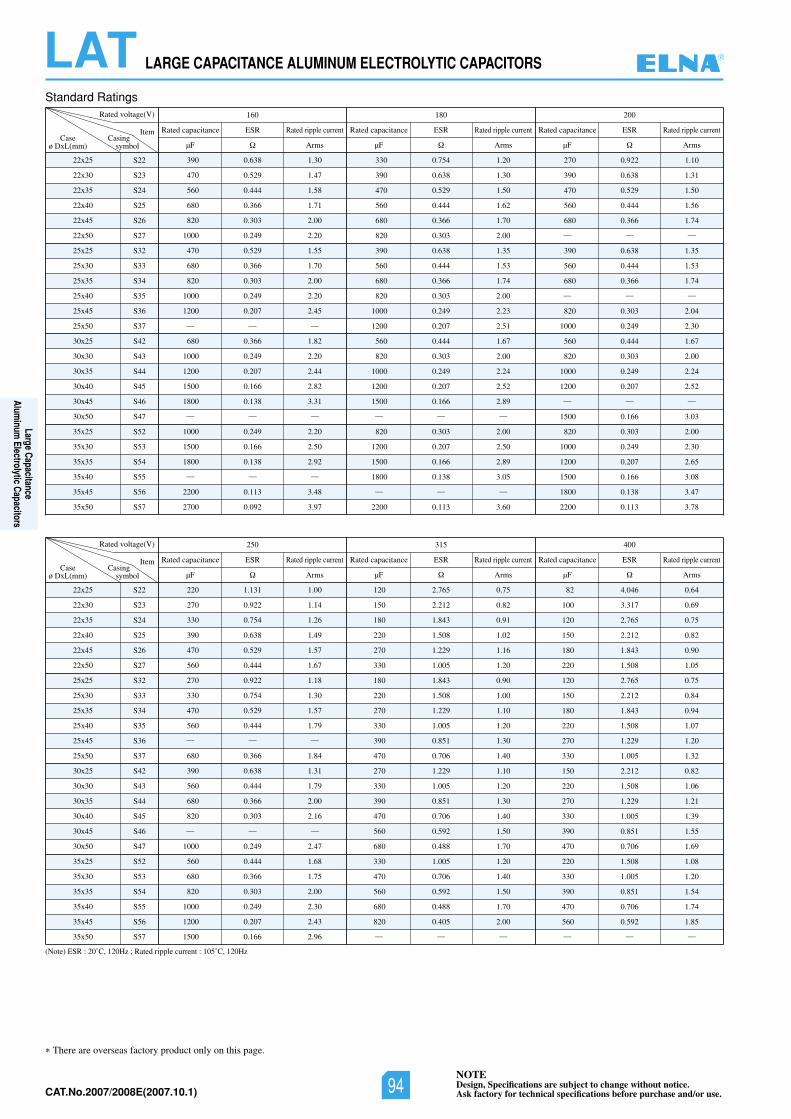
NOTEDesign, Specifications are subject to change without notice.Ask factory for technical specifications before purchase and/or use.CAT.No.2006/2007E(2006.10.1)
LAT LARGE CAPACITANCE ALUMINUM ELECTROLYTIC CAPACITORS
There are overseas factory product only on this page.
Standard Ratings
(Note) ESR : 20˚C, 120Hz ; Rated ripple current : 105˚C, 120Hz
22x25
22x30
22x35
22x40
22x45
22x50
25x25
25x30
25x35
25x40
25x45
25x50
30x25
30x30
30x35
30x40
30x45
30x50
35x25
35x30
35x35
35x40
35x45
35x50
S22
S23
S24
S25
S26
S27
S32
S33
S34
S35
S36
S37
S42
S43
S44
S45
S46
S47
S52
S53
S54
S55
S56
S57
Rated voltage(V) 002081061
ItemCase
ø DxL(mm)
390 0.638 1.30
470 0.529 1.47
560 0.444 1.58
680 0.366 1.71
820 0.303 2.00
1000 0.249 2.20
470 0.529 1.55
680 0.366 1.70
820 0.303 2.00
1000 0.249 2.20
1200 0.207 2.45
— — —
680 0.366 1.82
1000 0.249 2.20
1200 0.207 2.44
1500 0.166 2.82
1800 0.138 3.31
— — —
1000 0.249 2.20
1500 0.166 2.50
1800 0.138 2.92
— — —
2200 0.113 3.48
2700 0.092 3.97
330 0.754 1.20
390 0.638 1.30
470 0.529 1.50
560 0.444 1.62
680 0.366 1.70
820 0.303 2.00
390 0.638 1.35
560 0.444 1.53
680 0.366 1.74
820 0.303 2.00
1000 0.249 2.23
1200 0.207 2.51
560 0.444 1.67
820 0.303 2.00
1000 0.249 2.24
1200 0.207 2.52
1500 0.166 2.89
— — —
820 0.303 2.00
1200 0.207 2.50
1500 0.166 2.89
1800 0.138 3.05
— — —
2200 0.113 3.60
270 0.922 1.10
390 0.638 1.31
470 0.529 1.50
560 0.444 1.56
680 0.366 1.74
— — —
390 0.638 1.35
560 0.444 1.53
680 0.366 1.74
— — —
820 0.303 2.04
1000 0.249 2.30
560 0.444 1.67
820 0.303 2.00
1000 0.249 2.24
1200 0.207 2.52
— — —
1500 0.166 3.03
820 0.303 2.00
1000 0.249 2.30
1200 0.207 2.65
1500 0.166 3.08
1800 0.138 3.47
2200 0.113 3.78
ESR
µF ArmsCasing
symbol
Rated capacitance Rated ripple current ESR
µF Arms
Rated capacitance Rated ripple current ESR
µF Arms
Rated capacitance Rated ripple current
22x25
22x30
22x35
22x40
22x45
22x50
25x25
25x30
25x35
25x40
25x45
25x50
30x25
30x30
30x35
30x40
30x45
30x50
35x25
35x30
35x35
35x40
35x45
35x50
S22
S23
S24
S25
S26
S27
S32
S33
S34
S35
S36
S37
S42
S43
S44
S45
S46
S47
S52
S53
S54
S55
S56
S57
Rated voltage(V) 004513052
ItemCase
ø DxL(mm)
220 1.131 1.00
270 0.922 1.14
330 0.754 1.26
390 0.638 1.49
470 0.529 1.57
560 0.444 1.67
270 0.922 1.18
330 0.754 1.30
470 0.529 1.57
560 0.444 1.79
— — —
680 0.366 1.84
390 0.638 1.31
560 0.444 1.79
680 0.366 2.00
820 0.303 2.16
— — —
1000 0.249 2.47
560 0.444 1.68
680 0.366 1.75
820 0.303 2.00
1000 0.249 2.30
1200 0.207 2.43
1500 0.166 2.96
120 2.765 0.75
150 2.212 0.82
180 1.843 0.91
220 1.508 1.02
270 1.229 1.16
330 1.005 1.20
180 1.843 0.90
220 1.508 1.00
270 1.229 1.10
330 1.005 1.20
390 0.851 1.30
470 0.706 1.40
270 1.229 1.10
330 1.005 1.20
390 0.851 1.30
470 0.706 1.40
560 0.592 1.50
680 0.488 1.70
330 1.005 1.20
470 0.706 1.40
560 0.592 1.50
680 0.488 1.70
820 0.405 2.00
— — —
82 4.046 0.64
100 3.317 0.69
120 2.765 0.75
150 2.212 0.82
180 1.843 0.90
220 1.508 1.05
120 2.765 0.75
150 2.212 0.84
180 1.843 0.94
220 1.508 1.07
270 1.229 1.20
330 1.005 1.32
150 2.212 0.82
220 1.508 1.06
270 1.229 1.21
330 1.005 1.39
390 0.851 1.55
470 0.706 1.69
220 1.508 1.08
330 1.005 1.20
390 0.851 1.54
470 0.706 1.74
560 0.592 1.85
— — —
ESR
µF ArmsCasing
symbol
Rated capacitance Rated ripple current ESR
µF Arms
Rated capacitance Rated ripple current ESR
µF Arms
Rated capacitance Rated ripple current
®
Large CapacitanceAlum
inum Electrolytic Capacitors
NOTEDesign, Specifications are subject to change without notice.Ask factory for technical specifications before purchase and/or use.94CAT.No.2007/2008E(2007.10.1)
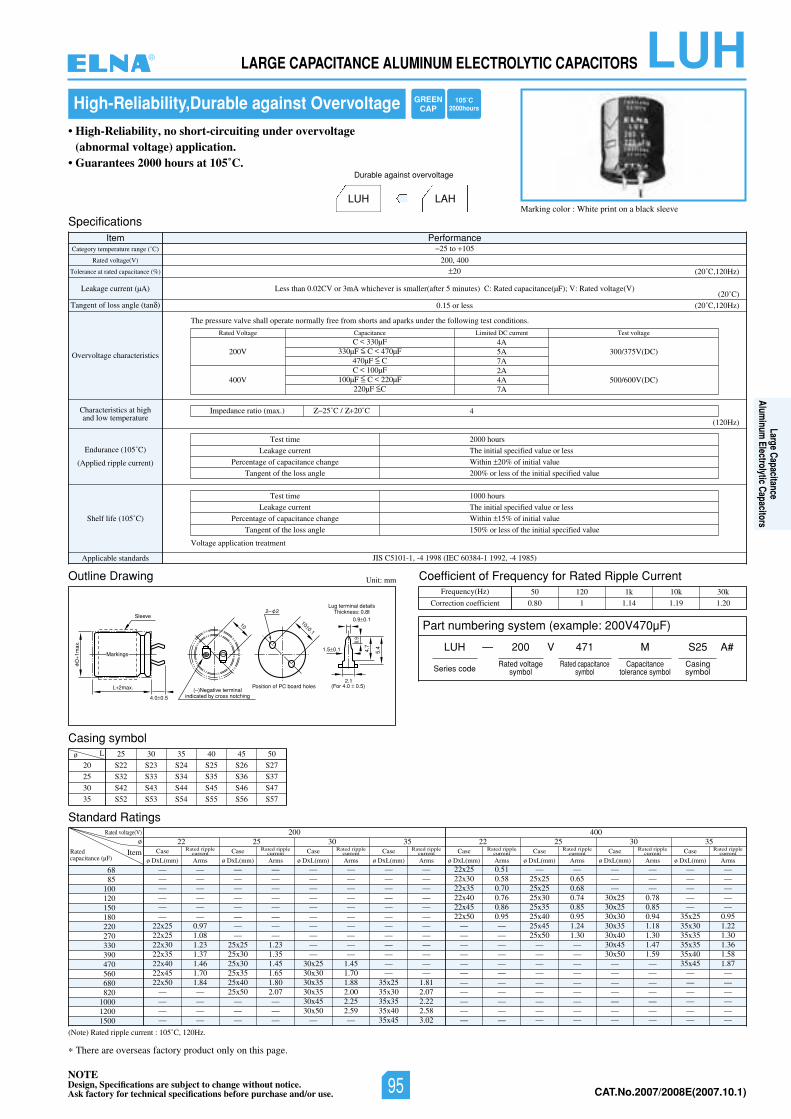
LUHLARGE CAPACITANCE ALUMINUM ELECTROLYTIC CAPACITORS
There are overseas factory product only on this page.
High-Reliability,Durable against Overvoltage
Marking color : White print on a black sleeve
• High-Reliability, no short-circuiting under overvoltage (abnormal voltage) application.
• Guarantees 2000 hours at 105˚C.
LUH LAH
Durable against overvoltage
Unit: mm
SpecificationsItem Performance
Category temperature range (˚C)
Rated voltage(V)
Tolerance at rated capacitance (%)
Leakage current (µA)
Tangent of loss angle (tan )
Overvoltage characteristics
Characteristics at highand low temperature
Endurance (105˚C)
(Applied ripple current)
Shelf life (105˚C)
Applicable standards JIS C5101-1, -4 1998 (IEC 60384-1 1992, -4 1985)
25 to 105
200, 40020
Less than 0.02CV or 3mA whichever is smaller(after 5 minutes) C: Rated capacitance(µF); V: Rated voltage(V)(20˚C)
(20˚C,120Hz)
(20˚C,120Hz)
(120Hz)
Test time
Leakage current
Percentage of capacitance change
Tangent of the loss angle
2000 hours
The initial specified value or less
Within 20% of initial value
200% or less of the initial specified value
Test time
Leakage current
Percentage of capacitance change
Tangent of the loss angle
1000 hours
The initial specified value or less
Within 15% of initial value
150% or less of the initial specified value
0.15 or less
The pressure valve shall operate normally free from shorts and aparks under the following test conditions.
Voltage application treatment
Impedance ratio (max.)
Rated Voltage
200V 300/375V(DC)4A5A7A2A4A7A
C 330µF330µF C 470µF
470µF CC 100µF
100µF C 220µF220µF C
500/600V(DC)400V
Capacitance Limited DC current Test voltage
425˚C / 20˚C
Outline Drawing
Casing symbol
L 2max.
D1m
ax.
Sleeve
4.0 0.5
Position of PC board holes(–)Negative terminal
indicated by cross notching
Lug terminal detailsThickness: 0.8t
(For 4.0 0.5) 2.1
0.9
1.5 0.1
5.4
0.9 0.1
4.7
100.1
10
2– 2
Markings
Coefficient of Frequency for Rated Ripple CurrentFrequency(Hz)
Correction coefficient
50 120 1k 10k 30k
0.80 1 1.14 1.19 1.20
Standard Ratings
(Note) Rated ripple current : 105˚C, 120Hz.
6885
100120150180220270330390470560680820
100012001500
20
25
30
35
25 30 35 40 45 50
S22 S23 S24 S25 S26 S27
S32 S33 S34 S35 S36 S37
S42 S43 S44 S45 S46 S47
S52 S53 S54 S55 S56 S57
ø
Lø
22400200
25 30 3522 25 30 35Item
— —— —— —— —— —— —
22x25 0.9722x25 1.0822x30 1.2322x35 1.3722x40 1.4622x45 1.7022x50 1.84
— —— —— —— —
— —— —— —— —— —— —— —— —
25x25 1.2325x30 1.3525x30 1.4525x35 1.6525x40 1.8025x50 2.07
— —— —— —
— —— —— —— —— —— —— —— —— —— —
30x25 1.4530x30 1.7030x35 1.8830x35 2.0030x45 2.2530x50 2.59
— —
— —— —— —— —— —— —— —— —— —— —— —— —
35x25 1.8135x30 2.0735x35 2.2235x40 2.5835x45 3.02
22x25 0.5122x30 0.5822x35 0.7022x40 0.7622x45 0.8622x50 0.95
— —— —— —— —— —— —— —— —— —— —— —
— —25x25 0.6525x25 0.6825x30 0.7425x35 0.8525x40 0.9525x45 1.2425x50 1.30
— —— —— —— —— —— —— —— —— —
— —— —— —
30x25 0.7830x25 0.8530x30 0.9430x35 1.1830x40 1.3030x45 1.4730x50 1.59
— —— —— —— —— —— —— —
— —— —— —— —— —
35x25 0.9535x30 1.2235x35 1.3035x35 1.3635x40 1.5835x45 1.87
— —— —— —— —— —— —
Case
ø DxL(mm) ArmsRatedcapacitance (µF)
Rated voltage(V)
Rated ripplecurrent Case
ø DxL(mm) Arms
Rated ripplecurrent Case
ø DxL(mm) Arms
Rated ripplecurrent Case
ø DxL(mm) Arms
Rated ripplecurrent Case
ø DxL(mm) Arms
Rated ripplecurrent Case
ø DxL(mm) Arms
Rated ripplecurrent Case
ø DxL(mm) Arms
Rated ripplecurrent Case
ø DxL(mm) Arms
Rated ripplecurrent
NOTEDesign, Specifications are subject to change without notice.Ask factory for technical specifications before purchase and/or use. CAT.No.2006/2007E(2006.10.1)
Part numbering system (example: 200V470µF)
LUH — V
Series code
200 471 M
Rated voltagesymbol
Rated capacitancesymbol
Capacitancetolerance symbol
S25
Casingsymbol
A#
GREENCAP
105˚C2000hours
®
Large CapacitanceAlum
inum Electrolytic Capacitors
NOTEDesign, Specifications are subject to change without notice.Ask factory for technical specifications before purchase and/or use. 95 CAT.No.2007/2008E(2007.10.1)
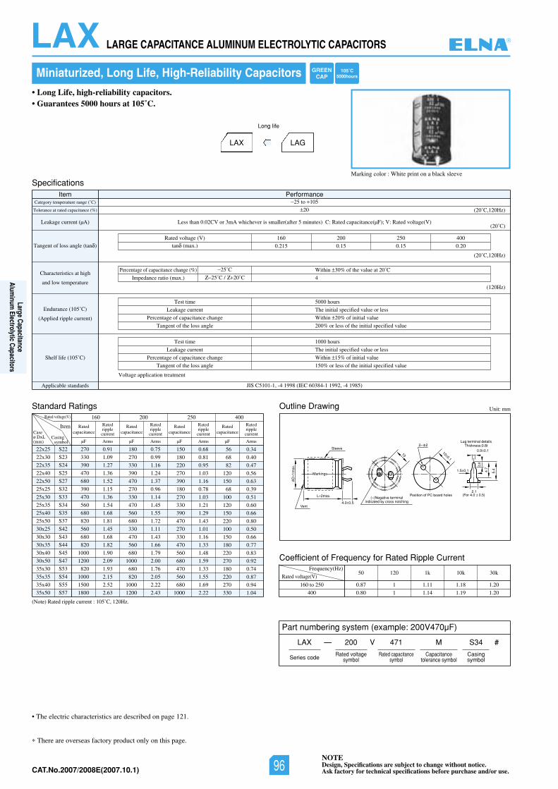
NOTEDesign, Specifications are subject to change without notice.Ask factory for technical specifications before purchase and/or use.CAT.No.2006/2007E(2006.10.1)
LAX LARGE CAPACITANCE ALUMINUM ELECTROLYTIC CAPACITORS
There are overseas factory product only on this page.
Miniaturized, Long Life, High-Reliability Capacitors
Marking color : White print on a black sleeve
• Long Life, high-reliability capacitors.• Guarantees 5000 hours at 105˚C.
LAX LAG
Long life
Unit: mm
SpecificationsItem Performance
Category temperature range (˚C)
Tolerance at rated capacitance (%)
Leakage current (µA)
Tangent of loss angle (tan )
Characteristics at high
and low temperature
Endurance (105˚C)
(Applied ripple current)
Shelf life (105˚C)
Applicable standards JIS C5101-1, -4 1998 (IEC 60384-1 1992, -4 1985)
25 to 105
20
Less than 0.02CV or 3mA whichever is smaller(after 5 minutes) C: Rated capacitance(µF); V: Rated voltage(V)(20˚C)
(20˚C,120Hz)
(20˚C,120Hz)
(120Hz)
Percentage of capacitance change (%) Within 30% of the value at 20˚C
4Impedance ratio (max.)
25˚C
25˚C / 20˚C
Outline Drawing
L 2max.
D1m
ax.
Sleeve
Vent4.0 0.5
Position of PC board holes(–)Negative terminal
indicated by cross notching
Lug terminal detailsThickness:0.8t
(For 4.0 0.5) 2.1
0.9
1.5 0.1
0.9 0.1
5.4 4.7
100.1
10
2– 2
Markings
Standard Ratings
Test time
Leakage current
Percentage of capacitance change
Tangent of the loss angle
5000 hours
The initial specified value or less
Within 20% of initial value
200% or less of the initial specified value
Test time
Leakage current
Percentage of capacitance change
Tangent of the loss angle
1000 hours
The initial specified value or less
Within 15% of initial value
150% or less of the initial specified value
Voltage application treatment
004052002061)V(egatlovdetaR
0.215 0.15 0.15 0.20tan (max.)
22x25
22x30
22x35
22x40
22x50
25x25
25x30
25x35
25x40
25x50
30x25
30x30
30x35
30x40
30x50
35x30
35x35
35x40
35x50
S22
S23
S24
S25
S27
S32
S33
S34
S35
S37
S42
S43
S44
S45
S47
S53
S54
S55
S57
Rated voltage(V) 160 200 250 400
ItemCaseø DxL(mm)
270 0.91
330 1.09
390 1.27
470 1.36
680 1.52
390 1.15
470 1.36
560 1.54
680 1.68
820 1.81
560 1.45
680 1.68
820 1.82
1000 1.90
1200 2.09
820 1.93
1000 2.15
1500 2.52
1800 2.63
180 0.75
270 0.99
330 1.16
390 1.24
470 1.37
270 0.96
330 1.14
470 1.45
560 1.55
680 1.72
330 1.11
470 1.43
560 1.66
680 1.79
1000 2.00
680 1.76
820 2.05
1000 2.22
1200 2.43
150 0.68
180 0.81
220 0.95
270 1.03
390 1.16
180 0.78
270 1.03
330 1.21
390 1.29
470 1.43
270 1.01
330 1.16
470 1.33
560 1.48
680 1.59
470 1.33
560 1.55
680 1.69
1000 2.22
56 0.34
68 0.40
82 0.47
120 0.56
150 0.63
68 0.39
100 0.51
120 0.60
150 0.66
220 0.80
100 0.50
150 0.66
180 0.77
220 0.83
270 0.92
180 0.74
220 0.87
270 0.94
330 1.04
µF Arms
Ratedripplecurrent
Ratedcapacitance
µF Arms
Ratedripplecurrent
Ratedcapacitance
µF Arms
Ratedripplecurrent
Ratedcapacitance
µF Arms
Ratedripplecurrent
Ratedcapacitance
Casingsymbol
• The electric characteristics are described on page 121.
(Note) Rated ripple current : 105˚C, 120Hz.
Coefficient of Frequency for Rated Ripple Current
Rated voltage(V)
Frequency(Hz)
160 to 250
400
50 120 1k 10k 30k
0.87 1 1.11 1.18 1.20
0.80 1 1.14 1.19 1.20
Part numbering system (example: 200V470µF)
LAX — V
Series code
200 471 M
Rated voltagesymbol
Rated capacitancesymbol
Capacitancetolerance symbol
S34
Casingsymbol
#
GREENCAP
105˚C5000hours
®
Large CapacitanceAlum
inum Electrolytic Capacitors
NOTEDesign, Specifications are subject to change without notice.Ask factory for technical specifications before purchase and/or use.96CAT.No.2007/2008E(2007.10.1)
NOTEDesign, Specifications are subject to change without notice.Ask factory for technical specifications before purchase and/or use. CAT.No.2007/2008E(2007.10.1)
Aluminum Electrolytic Capacitors for Audio
ALUMINUM ELECTROLYTIC CAPACITORS FOR AUDIO®
97
Aluminum
Electolytic Capacitorsfor Audio
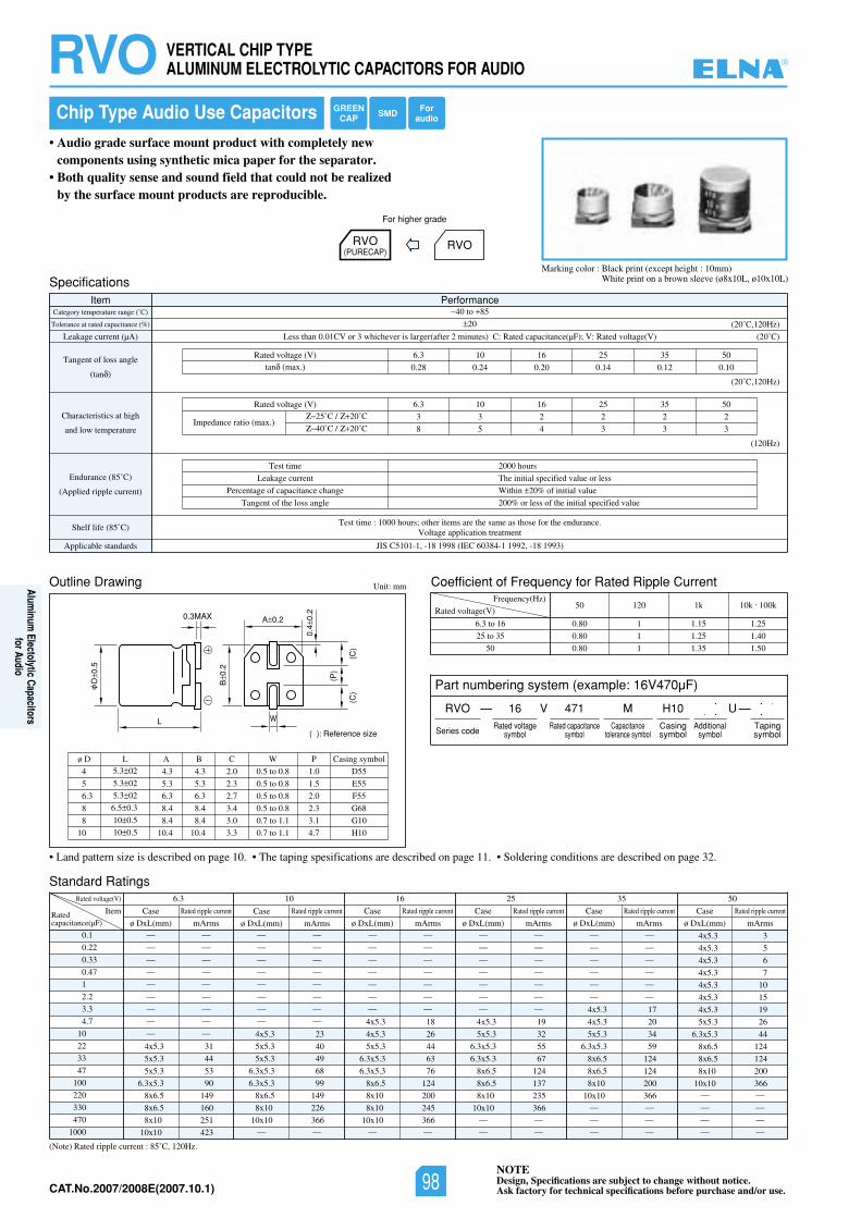
NOTEDesign, Specifications are subject to change without notice.Ask factory for technical specifications before purchase and/or use.CAT.No.2007/2008E(2007.10.1)
RVO VERTICAL CHIP TYPE ALUMINUM ELECTROLYTIC CAPACITORS FOR AUDIO
Standard Ratings
Chip Type Audio Use Capacitors
• Audio grade surface mount product with completely new components using synthetic mica paper for the separator.
• Both quality sense and sound field that could not be realized by the surface mount products are reproducible.
Marking color : Black print (except height : 10mm)White print on a brown sleeve (ø8x10L, ø10x10L)Specifications
Outline Drawing
Item PerformanceCategory temperature range (˚C)
Tolerance at rated capacitance (%)
Leakage current (µA)
Tangent of loss angle
(tan )
Characteristics at high
and low temperature
Endurance (85˚C)
(Applied ripple current)
Shelf life (85˚C)Test time : 1000 hours; other items are the same as those for the endurance.
Voltage application treatment
Applicable standards JIS C5101-1, -18 1998 (IEC 60384-1 1992, -18 1993)
40 to 85
20
Less than 0.01CV or 3 whichever is larger(after 2 minutes) C: Rated capacitance(µF); V: Rated voltage(V)
05535261013.6)V(egatlovdetaR
0.28 0.24 0.20 0.14 0.12 0.10tan (max.)
(20˚C)
(20˚C,120Hz)
(20˚C,120Hz)
(120Hz)
Test time
Leakage current
Percentage of capacitance change
Tangent of the loss angle
2000 hours
The initial specified value or less
Within 20% of initial value
200% or less of the initial specified value
05535261013.6)V(egatlovdetaR
3 3 2 2 2 2
8 5 4 3 3 3Impedance ratio (max.)
25˚C / 20˚C
40˚C / 20˚C
Unit: mm Coefficient of Frequency for Rated Ripple Current
Rated voltage(V)
Frequency(Hz)
6.3 to 16
25 to 35
50
50 120 1k 10k . 100k
0.80 1 1.15 1.25
0.80 1 1.25 1.40
0.80 1 1.35 1.50
(Note) Rated ripple current : 85˚C, 120Hz.
0.1
0.22
0.33
0.47
1
2.2
3.3
4.7
10
22
33
47
100
220
330
470
1000
Rated voltage(V) 05535261013.6
ItemRatedcapacitance(µF)
— —
— —
— —
— —
— —
— —
— —
— —
— —
4x5.3 31
5x5.3 44
5x5.3 53
6.3x5.3 90
8x6.5 149
8x6.5 160
8x10 251
10x10 423
Case
ø DxL(mm) mArms
Rated ripple current
— —
— —
— —
— —
— —
— —
— —
— —
4x5.3 23
5x5.3 40
5x5.3 49
6.3x5.3 68
6.3x5.3 99
8x6.5 149
8x10 226
10x10 366— —
— —
— —
— —
— —
— —
— —
— —
4x5.3 18
4x5.3 26
5x5.3 44
6.3x5.3 63
6.3x5.3 76
8x6.5 124
8x10 200
8x10 245
10x10 366— —
— —
— —
— —
— —
— —
— —
— —
4x5.3 19
5x5.3 32
6.3x5.3 55
6.3x5.3 67
8x6.5 124
8x6.5 137
8x10 235
10x10 366— —
— —
— —
— —
— —
— —
— —
— —
4x5.3 17
4x5.3 20
5x5.3 34
6.3x5.3 59
8x6.5 124
8x6.5 124
8x10 200
10x10 366— —
— —
— —
4x5.3 3
4x5.3 5
4x5.3 6
4x5.3 7
4x5.3 10
4x5.3 15
4x5.3 19
5x5.3 26
6.3x5.3 44
8x6.5 124
8x6.5 124
8x10 200
10x10 366— —
— —
— —
— —
Case
ø DxL(mm) mArms
Rated ripple current Case
ø DxL(mm) mArms
Rated ripple current Case
ø DxL(mm) mArms
Rated ripple current Case
ø DxL(mm) mArms
Rated ripple current Case
ø DxL(mm) mArms
Rated ripple current
RVO(PURECAP)
RVO
For higher grade
4
5
6.3
8
8
10
ø D5.3 02
5.3 02
5.3 02
6.5 0.3
10 0.5
10 0.5
L
4.3
5.3
6.3
8.4
8.4
10.4
4.3
5.3
6.3
8.4
8.4
10.4
A B
2.0
2.3
2.7
3.4
3.0
3.3
C
0.5 to 0.8
0.5 to 0.8
0.5 to 0.8
0.5 to 0.8
0.7 to 1.1
0.7 to 1.1
W
D55
E55
F55
G68
G10
H10
Casing symbol
1.0
1.5
2.0
2.3
3.1
4.7
P
• Land pattern size is described on page 10. • The taping spesifications are described on page 11. • Soldering conditions are described on page 32.
Part numbering system (example: 16V470µF)
RVO — V
Series code
16 471 MRated voltage
symbolRated capacitance
symbolCapacitance
tolerance symbol
H10Casingsymbol
—Tapingsymbol
Additionalsymbol
U
GREENCAP SMD For
audio
L
D0.
5
B0.
2
(P)
(C)
(C)
0.4
0.2
A 0.2
( ): Reference size
0.3MAX
W
®
98
Aluminum
Electolytic Capacitorsfor Audio
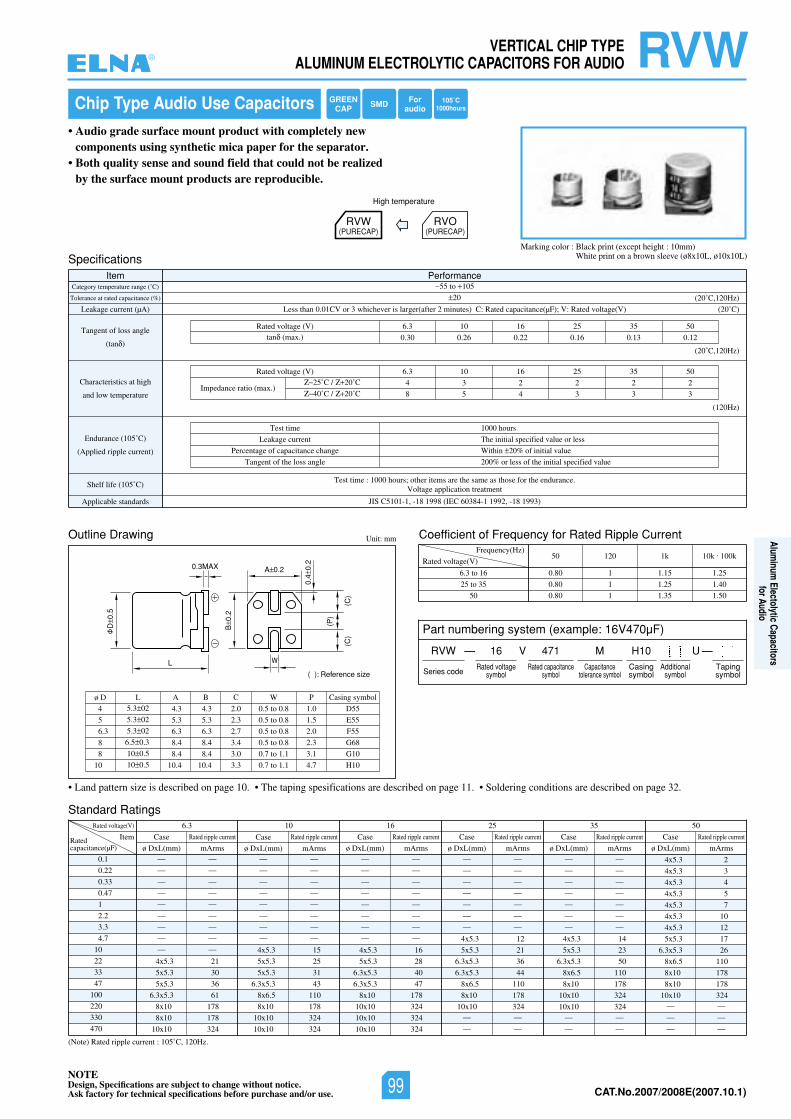
NOTEDesign, Specifications are subject to change without notice.Ask factory for technical specifications before purchase and/or use. CAT.No.2007/2008E(2007.10.1)
RVWVERTICAL CHIP TYPE ALUMINUM ELECTROLYTIC CAPACITORS FOR AUDIO
Standard Ratings
Chip Type Audio Use Capacitors
• Audio grade surface mount product with completely new components using synthetic mica paper for the separator.
• Both quality sense and sound field that could not be realized by the surface mount products are reproducible.
Marking color : Black print (except height : 10mm)White print on a brown sleeve (ø8x10L, ø10x10L)Specifications
Outline Drawing
Item PerformanceCategory temperature range (˚C)
Tolerance at rated capacitance (%)
Leakage current (µA)
Tangent of loss angle
(tan )
Characteristics at high
and low temperature
Endurance (105˚C)
(Applied ripple current)
Shelf life (105˚C)Test time : 1000 hours; other items are the same as those for the endurance.
Voltage application treatment
Applicable standards JIS C5101-1, -18 1998 (IEC 60384-1 1992, -18 1993)
55 to 105
20
Less than 0.01CV or 3 whichever is larger(after 2 minutes) C: Rated capacitance(µF); V: Rated voltage(V)
05535261013.6)V(egatlovdetaR
0.30 0.26 0.22 0.16 0.13 0.12tan (max.)
(20˚C)
(20˚C,120Hz)
(20˚C,120Hz)
(120Hz)
Test time
Leakage current
Percentage of capacitance change
Tangent of the loss angle
1000 hours
The initial specified value or less
Within 20% of initial value
200% or less of the initial specified value
05535261013.6)V(egatlovdetaR
4 3 2 2 2 2
8 5 4 3 3 3Impedance ratio (max.)
25˚C / 20˚C
40˚C / 20˚C
Unit: mm Coefficient of Frequency for Rated Ripple Current
Rated voltage(V)
Frequency(Hz)
6.3 to 16
25 to 35
50
50 120 1k 10k . 100k
0.80 1 1.15 1.25
0.80 1 1.25 1.40
0.80 1 1.35 1.50
(Note) Rated ripple current : 105˚C, 120Hz.
0.1
0.22
0.33
0.47
1
2.2
3.3
4.7
10
22
33
47
100
220
330
470
Rated voltage(V) 05535261013.6
ItemRatedcapacitance(µF)
— —
— —
— —
— —
— —
— —
— —
— —
— —
4x5.3 21
5x5.3 30
5x5.3 36
6.3x5.3 61
8x10 178
8x10 178
10x10 324
Case
ø DxL(mm) mArms
Rated ripple current
— —
— —
— —
— —
— —
— —
— —
— —
4x5.3 15
5x5.3 25
5x5.3 31
6.3x5.3 43
8x6.5 110
8x10 178
10x10 324
10x10 324
— —
— —
— —
— —
— —
— —
— —
— —
4x5.3 16
5x5.3 28
6.3x5.3 40
6.3x5.3 47
8x10 178
10x10 324
10x10 324
10x10 324
— —
— —
— —
— —
— —
— —
— —
4x5.3 12
5x5.3 21
6.3x5.3 36
6.3x5.3 44
8x6.5 110
8x10 178
10x10 324— —
— —
— —
— —
— —
— —
— —
— —
— —
4x5.3 14
5x5.3 23
6.3x5.3 50
8x6.5 110
8x10 178
10x10 324
10x10 324— —
— —
4x5.3 2
4x5.3 3
4x5.3 4
4x5.3 5
4x5.3 7
4x5.3 10
4x5.3 12
5x5.3 17
6.3x5.3 26
8x6.5 110
8x10 178
8x10 178
10x10 324— —
— —
— —
Case
ø DxL(mm) mArms
Rated ripple current Case
ø DxL(mm) mArms
Rated ripple current Case
ø DxL(mm) mArms
Rated ripple current Case
ø DxL(mm) mArms
Rated ripple current Case
ø DxL(mm) mArms
Rated ripple current
RVW(PURECAP)
RVO(PURECAP)
High temperature
4
5
6.3
8
8
10
ø D5.3 02
5.3 02
5.3 02
6.5 0.3
10 0.5
10 0.5
L
4.3
5.3
6.3
8.4
8.4
10.4
4.3
5.3
6.3
8.4
8.4
10.4
A B
2.0
2.3
2.7
3.4
3.0
3.3
C
0.5 to 0.8
0.5 to 0.8
0.5 to 0.8
0.5 to 0.8
0.7 to 1.1
0.7 to 1.1
W
D55
E55
F55
G68
G10
H10
Casing symbol
1.0
1.5
2.0
2.3
3.1
4.7
P
• Land pattern size is described on page 10. • The taping spesifications are described on page 11. • Soldering conditions are described on page 32.
Part numbering system (example: 16V470µF)
RVW — V
Series code
16 471 MRated voltage
symbolRated capacitance
symbolCapacitance
tolerance symbol
H10Casingsymbol
—Tapingsymbol
Additionalsymbol
U
GREENCAP SMD 105˚C
1000hoursFor
audio
L
D0.
5
B0.
2
(P)
(C)
(C)
0.4
0.2
A 0.2
( ): Reference size
0.3MAX
W
®
99
Aluminum
Electolytic Capacitorsfor Audio
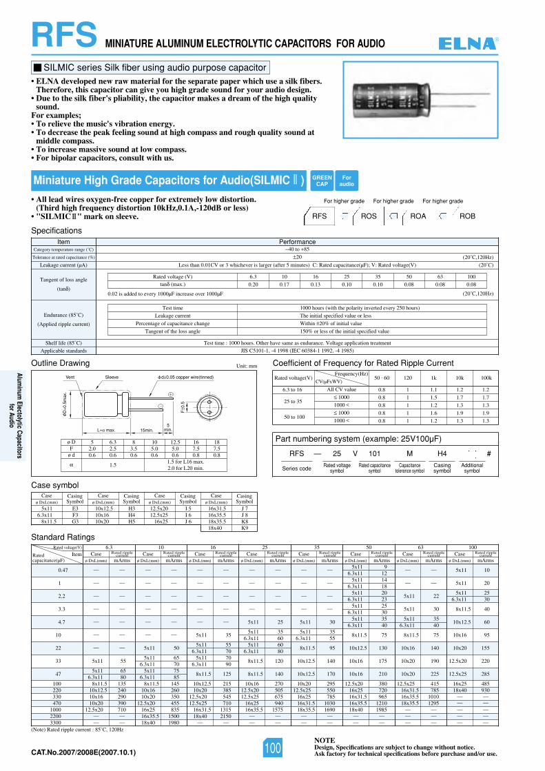
NOTEDesign, Specifications are subject to change without notice.Ask factory for technical specifications before purchase and/or use.CAT.No.2007/2008E(2007.10.1)
RFS MINIATURE ALUMINUM ELECTROLYTIC CAPACITORS FOR AUDIO
Miniature High Grade Capacitors for Audio(SILMIC II )• All lead wires oxygen-free copper for extremely low distortion.
(Third high frequency distortion 10kHz,0.1A,-120dB or less)• "SILMIC II" mark on sleeve. ROA ROBRFS ROS
For higher gradeFor higher gradeFor higher grade
SILMIC series Silk fiber using audio purpose capacitor• ELNA developed new raw material for the separate paper which use a silk fibers.
Therefore, this capacitor can give you high grade sound for your audio design.• Due to the silk fiber's pliability, the capacitor makes a dream of the high quality
sound.For examples;• To relieve the music's vibration energy.• To decrease the peak feeling sound at high compass and rough quality sound at
middle compass.• To increase massive sound at low compass.• For bipolar capacitors, consult with us.
Outline Drawing
Standard Ratings
Case symbol
Unit: mm
(Note) Rated ripple current : 85˚C, 120Hz
0.47
1
2.2
3.3
4.7
10
22
33
47
100220330470
100022003300
Rated voltage(V) 6.3 10 16 25 35 50 63 100ItemRated
capacitance(µF)
— —
— —
— —
— —
— —
— —
— —
5x11 55
5x11 656.3x11 80
8x11.5 13510x12.5 24010x16 29010x20 390
12.5x20 710— —— —
Caseø DxL(mm) mArms
Caseø DxL(mm)
CasingSymbol
Caseø DxL(mm)
CasingSymbol
Caseø DxL(mm)
CasingSymbol
Caseø DxL(mm)
CasingSymbol
Rated ripplecurrent Case
ø DxL(mm) mArms
Rated ripplecurrent Case
ø DxL(mm) mArms
Rated ripplecurrent Case
ø DxL(mm) mArms
Rated ripplecurrent Case
ø DxL(mm) mArms
Rated ripplecurrent Case
ø DxL(mm) mArms
Rated ripplecurrent Case
ø DxL(mm) mArms
Rated ripplecurrent Case
ø DxL(mm) mArms
Rated ripplecurrent
— —
— —
— —
— —
— —
— —
5x11 50
5x11 656.3x11 70
5x11 756.3x11 85
8x11.5 14510x16 26010x20 350
12.5x20 45516x25 83516x35.5 150018x40 1980
— —
— —
— —
— —
— —
5x11 35
5x11 556.3x11 70
5x11 706.3x11 90
8x11.5 125
10x12.5 21510x20 385
12.5x20 54512.5x25 710
16x31.5 131518x40 2150
— —
— —
— —
— —
— —
5x11 25
5x11 356.3x11 60
5x11 606.3x11 80
8x11.5 120
8x11.5 140
10x16 27012.5x20 50512.5x25 675
16x25 94016x35.5 1575
— —— —
— —
— —
— —
— —
5x11 30
5x11 356.3x11 55
8x11.5 95
10x12.5 140
10x12.5 170
10x20 29512.5x25 550
16x25 78516x31.5 103018x35.5 1690
— —— —
5x11 96.3x11 12
5x11 146.3x11 18
5x11 206.3x11 23
5x11 256.3x11 30
5x11 356.3x11 40
8x11.5 75
10x12.5 130
10x16 175
10x16 210
12.5x20 38016x25 72016x31.5 96516x35.5 121018x40 1985
— —— —
— —
— —
5x11 22
5x11 30
5x11 356.3x11 40
8x11.5 75
10x16 140
10x20 190
10x20 225
12.5x25 41516x31.5 78516x35.5 101018x35.5 1295
— —— —— —
5x11 10
5x11 20
5x11 256.3x11 30
8x11.5 40
10x12.5 60
10x16 95
10x20 155
12.5x20 220
12.5x25 285
16x25 48518x40 930
— —— —— —— —— —
SpecificationsItem Performance
Category temperature range (˚C)
Tolerance at rated capacitance (%)
Leakage current (µA)
Tangent of loss angle
(tan )
Endurance (85˚C)
(Applied ripple current)
Shelf life (85˚C) Test time : 1000 hours. Other have same as endurance. Voltage application treatment
Applicable standards JIS C5101-1, -4 1998 (IEC 60384-1 1992, -4 1985)
40 to 85
20
02()V(egatlovdetaR:V;)Fµ(ecnaticapacdetaR:C)setunim5retfa(regralsirevehcihw3roVC10.0nahtsseL ˚C)
(20˚C,120Hz)
(20˚C,120Hz)
Test time
Leakage current
Percentage of capacitance change
Tangent of the loss angle
1000 hours (with the polarity inverted every 250 hours)
The initial specified value or less
Within 20% of initial value
150% or less of the initial specified value
0013605535261013.6)V(egatlovdetaR
0.20 0.17 0.13 0.10 0.10 0.08 0.08 0.08tan (max.)
L max. 15min.5
min.
Sleeve
D0.
5max
.
F0.
5
d 0.05 copper wire(tinned)Vent
ø DF
ø d
5 6.3 8 10 12.5 16 182.0 2.5 3.5 5.0 5.0 7.5 7.50.6 0.6 0.6 0.6 0.6 0.8 0.8
1.51.5 for L16 max.2.0 for L20 min.
0.02 is added to every 1000µF increase over 1000µF
Coefficient of Frequency for Rated Ripple Current
Rated voltage(V)Frequency(Hz)
6.3 to 16
25 to 35
50 to 100
All CV value
1000
1000
1000
1000
50 . 60 120 1k 10k 100k
0.8 1 1.1 1.2 1.2
0.8 1 1.5 1.7 1.7
0.8 1 1.2 1.3 1.3
0.8 1 1.6 1.9 1.9
0.8 1 1.2 1.3 1.3
CV(µFxWV)
5x11 E36.3x11 F3
8x11.5 G3
10x12.5 H310x16 H410x20 H5
16x31.5 J 716x35.5 J 818x35.5 K818x40 K9
12.5x20 I 512.5x25 I 6
16x25 J 6
Part numbering system (example: 25V100µF)
RFS — V
Series code
25 101 M H4 #
Rated voltagesymbol
Rated capacitancesymbol
Capacitancetolerance symbol
Casingsymbol
Additionalsymbol
GREENCAP
Foraudio
®
100
Aluminum
Electolytic Capacitorsfor Audio
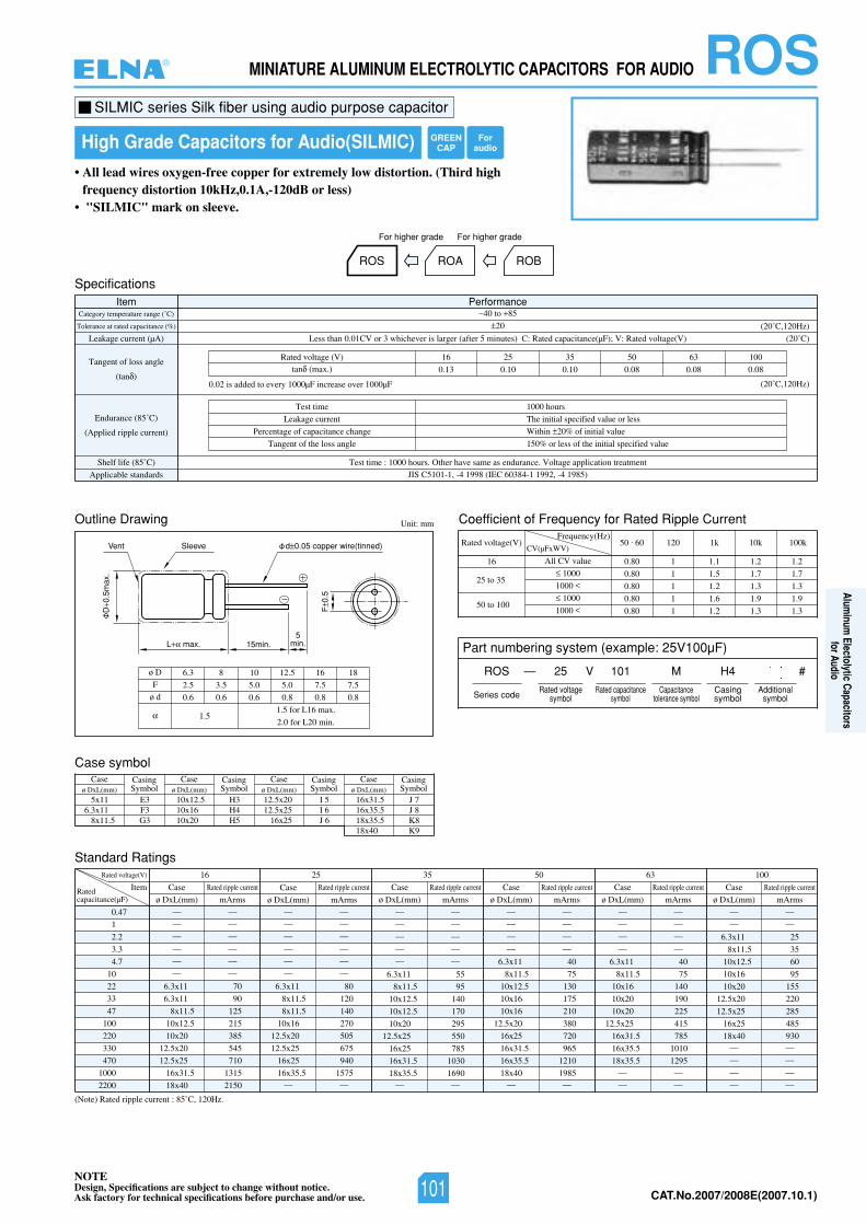
NOTEDesign, Specifications are subject to change without notice.Ask factory for technical specifications before purchase and/or use. CAT.No.2007/2008E(2007.10.1)
ROSMINIATURE ALUMINUM ELECTROLYTIC CAPACITORS FOR AUDIO
High Grade Capacitors for Audio(SILMIC)
• All lead wires oxygen-free copper for extremely low distortion. (Third highfrequency distortion 10kHz,0.1A,-120dB or less)
• "SILMIC" mark on sleeve.
ROA ROBROS
For higher gradeFor higher grade
SILMIC series Silk fiber using audio purpose capacitor
SpecificationsItem Performance
Category temperature range (˚C)
Tolerance at rated capacitance (%)
Leakage current (µA)
Tangent of loss angle
(tan )
Endurance (85˚C)
(Applied ripple current)
Shelf life (85˚C) Test time : 1000 hours. Other have same as endurance. Voltage application treatment
Applicable standards JIS C5101-1, -4 1998 (IEC 60384-1 1992, -4 1985)
40 to 85
20
02()V(egatlovdetaR:V;)Fµ(ecnaticapacdetaR:C)setunim5retfa(regralsirevehcihw3roVC10.0nahtsseL ˚C)
(20˚C,120Hz)
(20˚C,120Hz)0.02 is added to every 1000µF increase over 1000µF
Outline Drawing Unit: mm
L max. 15min.5
min.
Sleeve
D0.
5max
.
F0.
5
d 0.05 copper wire(tinned)Vent
Coefficient of Frequency for Rated Ripple Current
Rated voltage(V)Frequency(Hz)
16
25 to 35
50 to 100
All CV value
1000
1000
1000
1000
50 . 60 120 1k 10k 100k
0.80 1 1.1 1.2 1.2
0.80 1 1.5 1.7 1.7
0.80 1 1.2 1.3 1.3
0.80 1 1.6 1.9 1.9
0.80 1 1.2 1.3 1.3
CV(µFxWV)
0013605535261)V(egatlovdetaR
0.13 0.10 0.10 0.08 0.08 0.08tan (max.)
Test time
Leakage current
Percentage of capacitance change
Tangent of the loss angle
1000 hours
The initial specified value or less
Within 20% of initial value
150% or less of the initial specified value
ø D
F
ø d
6.3 8 10 12.5 16 18
2.5 3.5 5.0 5.0 7.5 7.5
0.6 0.6 0.6 0.8 0.8 0.8
1.51.5 for L16 max.
2.0 for L20 min.
Standard Ratings
(Note) Rated ripple current : 85˚C, 120Hz.
0.47
1
2.2
3.3
4.7
10
22
33
47
100
220
330
470
1000
2200
Rated voltage(V) 0013605535261
ItemRatedcapacitance(µF)
— —
— —
— —
— —
— —
— —
6.3x11 70
6.3x11 90
8x11.5 125
10x12.5 215
10x20 385
12.5x20 545
12.5x25 710
16x31.5 1315
18x40 2150
Case
ø DxL(mm) mArms
Rated ripple current
— —
— —
— —
— —
— —
— —
6.3x11 80
8x11.5 120
8x11.5 140
10x16 270
12.5x20 505
12.5x25 675
16x25 940
16x35.5 1575— —
— —
— —
— —
— —
— —
6.3x11 55
8x11.5 95
10x12.5 140
10x12.5 170
10x20 295
12.5x25 550
16x25 785
16x31.5 1030
18x35.5 1690— —
— —
— —
— —
— —
6.3x11 40
8x11.5 75
10x12.5 130
10x16 175
10x16 210
12.5x20 380
16x25 720
16x31.5 965
16x35.5 1210
18x40 1985— —
— —
— —
— —
— —
6.3x11 40
8x11.5 75
10x16 140
10x20 190
10x20 225
12.5x25 415
16x31.5 785
16x35.5 1010
18x35.5 1295— —
— —
— —
— —
6.3x11 25
8x11.5 35
10x12.5 60
10x16 95
10x20 155
12.5x20 220
12.5x25 285
16x25 485
18x40 930— —
— —
— —
— —
Case
ø DxL(mm) mArms
Rated ripple current Case
ø DxL(mm) mArms
Rated ripple current Case
ø DxL(mm) mArms
Rated ripple current Case
ø DxL(mm) mArms
Rated ripple current Case
ø DxL(mm) mArms
Rated ripple current
Case symbolCase
ø DxL(mm)CasingSymbol
Caseø DxL(mm)
CasingSymbol
Caseø DxL(mm)
CasingSymbol
Caseø DxL(mm)
CasingSymbol
5x11 E36.3x11 F3
8x11.5 G3
10x12.5 H310x16 H410x20 H5
16x31.5 J 716x35.5 J 818x35.5 K818x40 K9
12.5x20 I 512.5x25 I 6
16x25 J 6
Part numbering system (example: 25V100µF)
ROS — V
Series code
25 101 M H4 #
Rated voltagesymbol
Rated capacitancesymbol
Capacitancetolerance symbol
Casingsymbol
Additionalsymbol
GREENCAP
Foraudio
®
101
Aluminum
Electolytic Capacitorsfor Audio
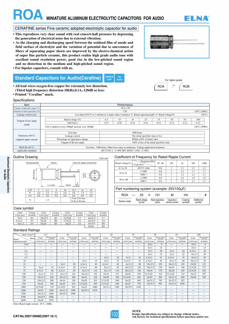
NOTEDesign, Specifications are subject to change without notice.Ask factory for technical specifications before purchase and/or use.CAT.No.2007/2008E(2007.10.1)
CERAFINE series Fine ceramic adopted electrolytic capacitor for audio• This reproduces very clear sound with real concert-hall presence by depressing
the generation of electrical noise due to external vibration.• As the charging and discharging speed between the oxidized film of anode and
field surface of electrolyte and the variation of potential due to unevenness offibers of separating paper sheets are improved by the electro-chemical actionof super fine particle ceramic, this product realize high grade audio tone withexcellent sound resolution power, good rise in the low-pitched sound regionand no distortion in the medium and high-pitched sound region.
• For bipolar capacitors, consult with us.
Standard Capacitors for Audio(Cerafine)
• All lead wires oxygen-free copper for extremely low distortion.(Third high frequency distortion 10kHz,0.1A,-120dB or less)
• Printed "Cerafine" mark.
ROA ROB
For higher grade
Outline Drawing Unit: mm
SpecificationsItem Performance
Category temperature range (˚C)
Tolerance at rated capacitance (%)
Leakage current (µA)
Tangent of loss angle
(tan )
Endurance (85˚C)
(Applied ripple current)
Shelf life (85˚C) Test time : 1000 hours. Other have same as endurance. Voltage application treatment
Applicable standards JIS C5101-1, -4 1998 (IEC 60384-1 1992, -4 1985)
40 to 85
20
02()V(egatlovdetaR:V;)Fµ(ecnaticapacdetaR:C)setunim5retfa(regralsirevehcihw3roVC10.0nahtsseL ˚C)
(20˚C,120Hz)
(20˚C,120Hz)
Test time
Leakage current
Percentage of capacitance change
Tangent of the loss angle
1000 hours
The initial specified value or less
Within 20% of initial value
150% or less of the initial specified value
0013605535261013.6)V(egatlovdetaR
0.23 0.20 0.16 0.16 0.14 0.12 0.12 0.12tan (max.)
L max. 15min.5
min.
Sleeve
D0.
5max
.
F0.
5
d 0.05 copper wire(tinned)Vent(except 5)
0.02 is added to every 1000µF increase over 1000µF
Coefficient of Frequency for Rated Ripple Current
Rated voltage(V)Frequency(Hz)
6.3 to 16
25 to 35
50 to 100
All CV value
1000
1000
1000
1000
50 . 60 120 1k 10k 100k
0.8 1 1.1 1.2 1.2
0.8 1 1.5 1.7 1.7
0.8 1 1.2 1.3 1.3
0.8 1 1.6 1.9 1.9
0.8 1 1.2 1.3 1.3
CV(µFxWV)
Standard Ratings
(Note) Rated ripple current : 85˚C, 120Hz
0.47
1
2.2
3.3
4.7
10
22
33
47
100
220
330
470
1000
2200
3300
4700
6800
Rated voltage(V) 6.3 10 16 25 35 50 63 100
ItemRatedcapacitance(µF)
— —
— —
— —
— —
— —
— —
— —
5x11 55
6.3x11 80
8x11.5 135
10x12.5 240
10x12.5 290
10x16 390
12.5x20 710
16x25 1280
16x31.5 1660
16x35.5 2000
18x40 2550
Case
ø DxL(mm) mArms
Rated ripplecurrent Case
ø DxL(mm) mArms
Rated ripplecurrent Case
ø DxL(mm) mArms
Rated ripplecurrent Case
ø DxL(mm) mArms
Rated ripplecurrent Case
ø DxL(mm) mArms
Rated ripplecurrent Case
ø DxL(mm) mArms
Rated ripplecurrent Case
ø DxL(mm) mArms
Rated ripplecurrent Case
ø DxL(mm) mArms
Rated ripplecurrent
— —
— —
— —
— —
— —
— —
5x11 50
6.3x11 70
6.3x11 85
8x11.5 145
10x12.5 260
10x16 350
10x20 455
12.5x25 835
16x31.5 1500
18x35.5 1980— —
— —
— —
— —
— —
— —
— —
5x11 35
6.3x11 65
6.3x11 80
8x11.5 110
10x12.5 195
10x16 320
10x20 425
12.5x20 585
16x25 1080
18x35.5 1870— —
— —
— —
— —
— —
— —
— —
5x11 25
5x11 35
6.3x11 65
8x11.5 95
8x11.5 110
10x16 215
10x20 350
12.5x20 490
12.5x25 640
16x31.5 1180— —
— —
— —
— —
— —
— —
— —
— —
5x11 25
6.3x11 45
8x11.5 80
10x12.5 120
10x12.5 140
10x20 250
12.5x25 465
16x25 665
16x25 795
18x35.5 1430— —
— —
— —
— —
— —
— —
5x11 20
5x11 25
6.3x11 35
8x11.5 60
10x12.5 105
10x16 140
10x20 185
12.5x20 310
16x31.5 640
16x35.5 825
18x35.5 1050— —
— —
— —
— —
— —
5x11 9
5x11 14
5x11 20
5x11 25
6.3x11 35
6.3x11 50
10x12.5 105
10x12.5 130
10x16 170
12.5x20 310
16x25 585
16x31.5 785
16x35.5 985— —
— —
— —
— —
— —
5x11 9
5x11 14
6.3x11 20
8x11.5 30
8x11.5 40
10x12.5 70
10x20 125
12.5x20 175
12.5x25 230
16x25 395
18x40 760— —
— —
— —
— —
— —
— —
— —
ROA MINIATURE ALUMINUM ELECTROLYTIC CAPACITORS FOR AUDIO
Part numbering system (example: 25V100µF)
ROA — V
Series code
25 101 M H4 #
Rated voltagesymbol
Rated capacitancesymbol
Capacitancetolerance symbol
Casingsymbol
Additionalsymbol
Case symbolCase
ø DxL(mm)CasingSymbol
Caseø DxL(mm)
CasingSymbol
Caseø DxL(mm)
CasingSymbol
Caseø DxL(mm)
CasingSymbol
5x11 E36.3x11 F3
8x11.5 G3
10x12.5 H310x16 H410x20 H5
16x31.5 J 716x35.5 J 818x35.5 K818x40 K9
12.5x20 I 512.5x25 I 6
16x25 J 6
ø DF
ø d
5 6.3 8 10 12.5 16 182.0 2.5 3.5 5.0 5.0 7.5 7.50.6 0.6 0.6 0.6 0.8 0.8 0.8
1.51.5 for L16 max.2.0 for L20 min.
GREENCAP
Foraudio
®
102
Aluminum
Electolytic Capacitorsfor Audio
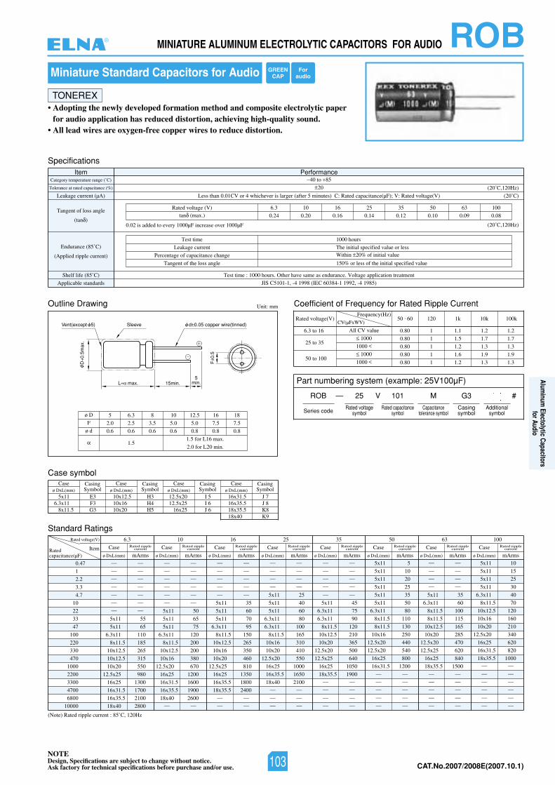
NOTEDesign, Specifications are subject to change without notice.Ask factory for technical specifications before purchase and/or use. CAT.No.2007/2008E(2007.10.1)
ROBMINIATURE ALUMINUM ELECTROLYTIC CAPACITORS FOR AUDIO
Miniature Standard Capacitors for Audio
• Adopting the newly developed formation method and composite electrolytic paperfor audio application has reduced distortion, achieving high-quality sound.
• All lead wires are oxygen-free copper wires to reduce distortion.
TONEREX
Outline Drawing Unit: mm
SpecificationsItem Performance
Category temperature range (˚C)
Tolerance at rated capacitance (%)
Leakage current (µA)
Tangent of loss angle
(tan )
Endurance (85˚C)
(Applied ripple current)
Shelf life (85˚C) Test time : 1000 hours. Other have same as endurance. Voltage application treatment
Applicable standards JIS C5101-1, -4 1998 (IEC 60384-1 1992, -4 1985)
40 to 85
20
02()V(egatlovdetaR:V;)Fµ(ecnaticapacdetaR:C)setunim5retfa(regralsirevehcihw4roVC10.0nahtsseL ˚C)
(20˚C,120Hz)
(20˚C,120Hz)
Test time
Leakage current
Percentage of capacitance change
Tangent of the loss angle
1000 hours
The initial specified value or less
150% or less of the initial specified value
0013605535261013.6)V(egatlovdetaR
0.24 0.20 0.16 0.14 0.12 0.10 0.09 0.08tan (max.)
L max. 15min.5
min.
Sleeve
D0.
5max
.
F0.
5
d 0.05 copper wire(tinned)Vent(except 5)
0.02 is added to every 1000µF increase over 1000µF
Part numbering system (example: 25V100µF)
Coefficient of Frequency for Rated Ripple Current
Rated voltage(V)Frequency(Hz)
6.3 to 16
25 to 35
50 to 100
All CV value
1000
1000
1000
1000
50 . 60 120 1k 10k 100k
0.80 1 1.1 1.2 1.2
0.80 1 1.5 1.7 1.7
0.80 1 1.2 1.3 1.3
0.80 1 1.6 1.9 1.9
0.80 1 1.2 1.3 1.3
CV(µFxWV)
Case symbolCase
ø DxL(mm)CasingSymbol
Caseø DxL(mm)
CasingSymbol
Caseø DxL(mm)
CasingSymbol
Caseø DxL(mm)
CasingSymbol
5x11 E36.3x11 F3
8x11.5 G3
10x12.5 H310x16 H410x20 H5
16x31.5 J 716x35.5 J 818x35.5 K818x40 K9
12.5x20 I 512.5x25 I 6
16x25 J 6
Standard Ratings
(Note) Rated ripple current : 85˚C, 120Hz
0.47
1
2.2
3.3
4.7
10
22
33
47
100
220
330
470
1000
2200
3300
4700
6800
10000
Rated voltage(V) 6.3 10 16 25 35 50 63 100
ItemRatedcapacitance(µF)
— —
— —
— —
— —
— —
— —
— —
5x11 55
5x11 65
6.3x11 110
8x11.5 185
10x12.5 265
10x12.5 315
10x20 550
12.5x25 980
16x25 1300
16x31.5 1700
16x35.5 2100
18x40 2800
Case
ø DxL(mm) mArms
Rated ripplecurrent Case
ø DxL(mm) mArms
Rated ripplecurrent Case
ø DxL(mm) mArms
Rated ripplecurrent Case
ø DxL(mm) mArms
Rated ripplecurrent Case
ø DxL(mm) mArms
Rated ripplecurrent Case
ø DxL(mm) mArms
Rated ripplecurrent Case
ø DxL(mm) mArms
Rated ripplecurrent Case
ø DxL(mm) mArms
Rated ripplecurrent
— —
— —
— —
— —
— —
— —
5x11 50
5x11 65
5x11 75
6.3x11 120
8x11.5 200
10x12.5 200
10x16 380
12.5x20 670
16x25 1200
16x31.5 1600
16x35.5 1900
18x40 2600— —
— —
— —
— —
— —
— —
5x11 35
5x11 60
5x11 70
6.3x11 95
8x11.5 150
10x12.5 265
10x16 350
10x20 460
12.5x25 810
16x25 1350
16x35.5 1800
18x35.5 2400— —
— —
— —
— —
— —
— —
5x11 25
5x11 40
5x11 60
6.3x11 80
6.3x11 100
8x11.5 165
10x16 310
10x20 410
12.5x20 550
16x25 1000
16x35.5 1650
18x40 2100— —
— —
— —
— —
— —
— —
— —
— —
5x11 45
6.3x11 75
6.3x11 90
8x11.5 120
10x12.5 210
10x20 365
12.5x20 500
12.5x25 640
16x25 1050
18x35.5 1900— —
— —
— —
— —
— —
— —
— —
— —
5x11 35
6.3x11 60
8x11.5 100
8x11.5 115
10x12.5 165
10x20 285
12.5x20 470
12.5x25 620
16x25 840
18x35.5 1500— —
— —
— —
— —
— —
5x11 5
5x11 10
5x11 20
5x11 25
5x11 35
5x11 50
6.3x11 80
8x11.5 110
8x11.5 130
10x16 250
12.5x20 440
12.5x20 540
16x25 800
16x31.5 1200— —
— —
— —
— —
— —
5x11 10
5x11 15
5x11 25
5x11 30
6.3x11 40
8x11.5 70
10x12.5 120
10x16 160
10x20 210
12.5x20 340
16x25 620
16x31.5 820
18x35.5 1000— —
— —
— —
— —
— —
— —
ø D
F
ø d
5 6.3 8 10 12.5 16 18
2.0 2.5 3.5 5.0 5.0 7.5 7.5
0.6 0.6 0.6 0.6 0.8 0.8 0.8
1.51.5 for L16 max.
2.0 for L20 min.
Within 20% of initial value
ROB — V
Series code
25 101 M G3 #
Rated voltagesymbol
Rated capacitancesymbol
Capacitancetolerance symbol
Casingsymbol
Additionalsymbol
GREENCAP
Foraudio
®
103
Aluminum
Electolytic Capacitorsfor Audio
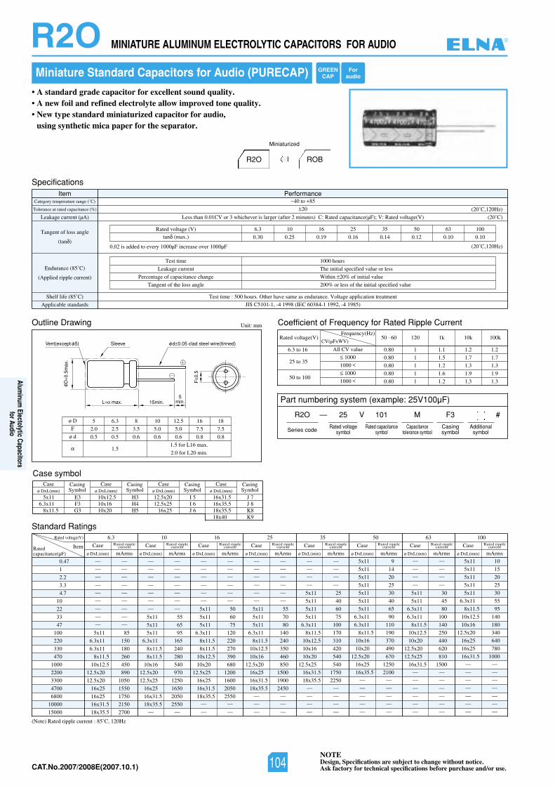
NOTEDesign, Specifications are subject to change without notice.Ask factory for technical specifications before purchase and/or use.CAT.No.2007/2008E(2007.10.1)
Miniature Standard Capacitors for Audio (PURECAP)
• A standard grade capacitor for excellent sound quality.• A new foil and refined electrolyte allow improved tone quality.• New type standard miniaturized capacitor for audio,
using synthetic mica paper for the separator.
Outline Drawing Unit: mm
L max. 15min.5
min.
Sleeve
D0.
5max
.
F0.
5
d 0.05 clad steel wire(tinned)Vent(except 5)
Coefficient of Frequency for Rated Ripple Current
Rated voltage(V)Frequency(Hz)
6.3 to 16
25 to 35
50 to 100
All CV value
1000
1000
1000
1000
50 . 60 120 1k 10k 100k
0.80 1 1.1 1.2 1.2
0.80 1 1.5 1.7 1.7
0.80 1 1.2 1.3 1.3
0.80 1 1.6 1.9 1.9
0.80 1 1.2 1.3 1.3
CV(µFxWV)
Standard Ratings
(Note) Rated ripple current : 85˚C, 120Hz
0.47
1
2.2
3.3
4.7
10
22
33
47
100
220
330
470
1000
2200
3300
4700
6800
10000
15000
Rated voltage(V) 6.3 10 16 25 35 50 63 100
ItemRatedcapacitance(µF)
— —
— —
— —
— —
— —
— —
— —
— —
— —
5x11 85
6.3x11 150
6.3x11 180
8x11.5 260
10x12.5 450
12.5x20 890
12.5x20 1050
16x25 1550
16x25 1750
16x31.5 2150
18x35.5 2700
Case
ø DxL(mm) mArms
Rated ripplecurrent Case
ø DxL(mm) mArms
Rated ripplecurrent Case
ø DxL(mm) mArms
Rated ripplecurrent Case
ø DxL(mm) mArms
Rated ripplecurrent Case
ø DxL(mm) mArms
Rated ripplecurrent Case
ø DxL(mm) mArms
Rated ripplecurrent Case
ø DxL(mm) mArms
Rated ripplecurrent Case
ø DxL(mm) mArms
Rated ripplecurrent
— —
— —
— —
— —
— —
— —
— —
5x11 55
5x11 65
5x11 95
6.3x11 165
8x11.5 240
8x11.5 280
10x16 540
12.5x20 970
12.5x25 1250
16x25 1650
16x31.5 2050
18x35.5 2550— —
— —
— —
— —
— —
— —
— —
5x11 50
5x11 60
5x11 75
6.3x11 120
8x11.5 220
8x11.5 270
10x12.5 390
10x20 680
12.5x25 1200
16x25 1600
16x31.5 2050
18x35.5 2550— —
— —
— —
— —
— —
— —
— —
— —
5x11 55
5x11 70
5x11 80
6.3x11 140
8x11.5 240
10x12.5 350
10x16 460
12.5x20 850
16x25 1500
16x31.5 1900
18x35.5 2450— —
— —
— —
— —
— —
— —
— —
5x11 25
5x11 40
5x11 60
5x11 75
6.3x11 100
8x11.5 170
10x12.5 310
10x16 420
10x20 540
12.5x25 540
16x31.5 1750
18x35.5 2250— —
— —
— —
— —
— —
— —
— —
— —
5x11 30
5x11 45
6.3x11 80
6.3x11 100
8x11.5 140
10x12.5 250
10x20 440
12.5x20 620
12.5x25 810
16x31.5 1500— —
— —
— —
— —
— —
— —
5x11 9
5x11 14
5x11 20
5x11 25
5x11 30
5x11 40
5x11 65
6.3x11 90
6.3x11 110
8x11.5 190
10x16 370
10x20 490
12.5x20 670
16x25 1250
16x35.5 2100— —
— —
— —
— —
— —
5x11 10
5x11 15
5x11 20
5x11 25
5x11 30
6.3x11 55
8x11.5 95
10x12.5 140
10x16 180
12.5x20 340
16x25 640
16x25 780
16x31.5 1000— —
— —
— —
— —
— —
— —
— —
ø D
F
ø d
5 6.3 8 10 12.5 16 18
2.0 2.5 3.5 5.0 5.0 7.5 7.5
0.5 0.5 0.6 0.6 0.6 0.8 0.8
1.51.5 for L16 max.
2.0 for L20 min.
R2O MINIATURE ALUMINUM ELECTROLYTIC CAPACITORS FOR AUDIO
R2O ROB
Miniaturized
SpecificationsItem Performance
Category temperature range (˚C)
Tolerance at rated capacitance (%)
Leakage current (µA)
Tangent of loss angle
(tan )
Endurance (85˚C)
(Applied ripple current)
Shelf life (85˚C) Test time : 500 hours. Other have same as endurance. Voltage application treatment
Applicable standards JIS C5101-1, -4 1998 (IEC 60384-1 1992, -4 1985)
40 to 85
20
02()V(egatlovdetaR:V;)Fµ(ecnaticapacdetaR:C)setunim2retfa(regralsirevehcihw3roVC10.0nahtsseL ˚C)
(20˚C,120Hz)
(20˚C,120Hz)
Test time
Leakage current
Percentage of capacitance change
Tangent of the loss angle
1000 hours
The initial specified value or less
Within 20% of initial value
200% or less of the initial specified value
0013605535261013.6)V(egatlovdetaR
0.30 0.25 0.19 0.16 0.14 0.12 0.10 0.10tan (max.)
0.02 is added to every 1000µF increase over 1000µF
Part numbering system (example: 25V100µF)
R2O — V
Series code
25 101 M F3 #
Rated voltagesymbol
Rated capacitancesymbol
Capacitancetolerance symbol
Casingsymbol
Additionalsymbol
Case symbolCase
ø DxL(mm)CasingSymbol
Caseø DxL(mm)
CasingSymbol
Caseø DxL(mm)
CasingSymbol
Caseø DxL(mm)
CasingSymbol
5x11 E36.3x11 F3
8x11.5 G3
10x12.5 H310x16 H410x20 H5
16x31.5 J 716x35.5 J 818x35.5 K818x40 K9
12.5x20 I 512.5x25 I 6
16x25 J 6
GREENCAP
Foraudio
®
104
Aluminum
Electolytic Capacitorsfor Audio
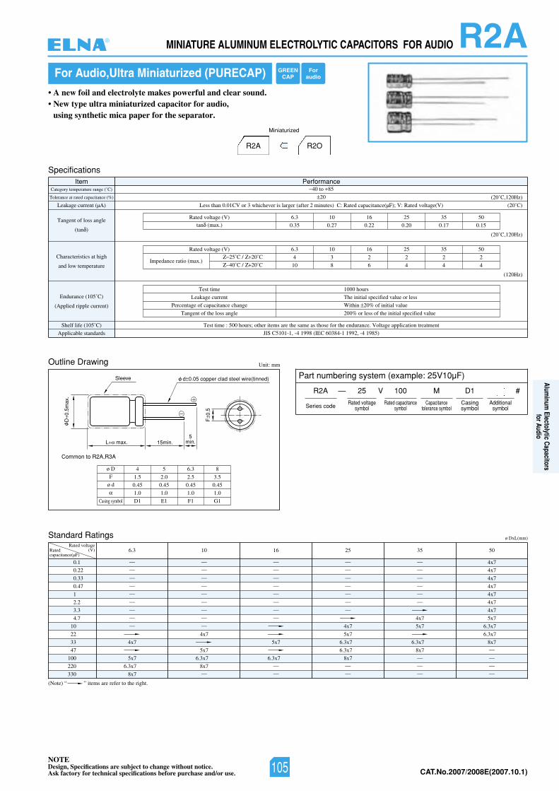
NOTEDesign, Specifications are subject to change without notice.Ask factory for technical specifications before purchase and/or use. CAT.No.2007/2008E(2007.10.1)
(Note) “ ” items are refer to the right.
For Audio,Ultra Miniaturized (PURECAP)
• A new foil and electrolyte makes powerful and clear sound.• New type ultra miniaturized capacitor for audio,
using synthetic mica paper for the separator.
Standard Ratings
0.1
0.22
0.33
0.47
1
2.2
3.3
4.7
10
22
33
47
100
220
330
Rated voltage(V) 6.3Rated
capacitance(µF)
—
—
—
—
—
—
—
—
—
4x7
5x7
6.3x7
8x7
R2AMINIATURE ALUMINUM ELECTROLYTIC CAPACITORS FOR AUDIO
SpecificationsItem Performance
Category temperature range (˚C)
Tolerance at rated capacitance (%)
Leakage current (µA)
Tangent of loss angle
(tan )
Characteristics at high
and low temperature
Endurance (105˚C)
(Applied ripple current)
Shelf life (105˚ tnemtaertnoitacilppaegatloV.ecnarudneehtrofesohtsaemasehterasmetirehto;sruoh005:emittseT)C
Applicable standards JIS C5101-1, -4 1998 (IEC 60384-1 1992, -4 1985)
40 to 85
20
02()V(egatlovdetaR:V;)Fµ(ecnaticapacdetaR:C)setunim2retfa(regralsirevehcihw3roVC10.0nahtsseL ˚C)
(20˚C,120Hz)
Test time
Leakage current
Percentage of capacitance change
Tangent of the loss angle
1000 hours
The initial specified value or less
Within 20% of initial value
200% or less of the initial specified value
05535261013.6)V(egatlovdetaR
0.35 0.27 0.22 0.20 0.17 0.15tan (max.)
(20˚C,120Hz)
(120Hz)
05535261013.6)V(egatlovdetaR
4 3 2 2 2 2
10 8 6 4 4 4Impedance ratio (max.)
25˚C / 20˚C
40˚C / 20˚C
R2A R2O
Miniaturized
Outline Drawing Unit: mm
L max. 15min.
Sleeve
D0.
5max
.
F0.
5
5min.
d 0.05 copper clad steel wire(tinned)
ø D
F
ø d
4 5 6.3 8
1.5 2.0 2.5 3.5
0.45 0.45 0.45 0.45
1.0 1.0 1.0 1.0
D1 E1 F1 G1
Common to R2A,R3A
Casing symbol
ø DxL(mm)
10
—
—
—
—
—
—
—
—
—
4x7
5x7
6.3x7
8x7—
16
—
—
—
—
—
—
—
—
5x7
6.3x7—
—
25
—
—
—
—
—
—
—
4x7
5x7
6.3x7
6.3x7
8x7—
—
35
—
—
—
—
—
—
4x7
5x7
6.3x7
8x7—
—
—
50
4x7
4x7
4x7
4x7
4x7
4x7
4x7
5x7
6.3x7
6.3x7
8x7—
—
—
—
Part numbering system (example: 25V10µF)
R2A — V
Series code
25 100 M D1 #
Rated voltagesymbol
Rated capacitancesymbol
Capacitancetolerance symbol
Casingsymbol
Additionalsymbol
GREENCAP
Foraudio
®
105
Aluminum
Electolytic Capacitorsfor Audio
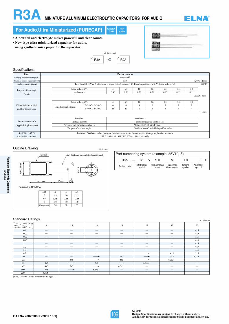
NOTEDesign, Specifications are subject to change without notice.Ask factory for technical specifications before purchase and/or use.CAT.No.2007/2008E(2007.10.1)
For Audio,Ultra Miniaturized (PURECAP)
• A new foil and electrolyte makes powerful and clear sound.• New type ultra miniaturized capacitor for audio,
using synthetic mica paper for the separator.
Standard Ratings
0.1
0.22
0.33
0.47
1
2.2
3.3
4.7
10
22
33
47
100
220
Rated voltage(V) 4 6.3 10 16 25 35 50Rated
capacitance(µF)
—
—
—
—
—
—
—
—
—
—
4x5
4x5
5x5
6.3x5
—
—
—
—
—
—
—
—
—
4x5
5x5
—
—
—
—
—
—
—
—
—
5x5
6.3x5—
—
—
—
—
—
—
—
—
4x5
5x5
6.3x5—
—
—
—
—
—
—
—
—
6.3x5—
—
—
—
—
—
—
—
—
—
4x5
5x5
6.3x5—
—
—
—
4x5
4x5
4x5
4x5
4x5
4x5
4x5
5x5
6.3x5—
—
—
—
—
05535261013.64)V(egatlovdetaR
6 4 3 2 2 2 2
16 10 8 6 4 4 4Impedance ratio (max.)
25˚C / 20˚C
40˚C / 20˚C
R2AR3A
Miniaturized
Outline Drawing Unit: mm
L max. 15min.
Sleeve
D0.
5max
.
F0.
5
5min.
d 0.05 copper clad steel wire(tinned)
ø D
F
ø d
4 5 6.3
1.5 2.0 2.5
0.45 0.45 0.45
1.0 1.0 1.0
D0 E0 F0
Common to R2A,R3A
Casing symbol
R3A MINIATURE ALUMINUM ELECTROLYTIC CAPACITORS FOR AUDIO
SpecificationsItem Performance
Category temperature range (˚C)
Tolerance at rated capacitance (%)
Leakage current (µA)
Tangent of loss angle
(tan )
Characteristics at high
and low temperature
Endurance (105˚C)
(Applied ripple current)
Shelf life (105˚ tnemtaertnoitacilppaegatloV.ecnarudneehtrofesohtsaemasehterasmetirehto;sruoh005:emittseT)C
Applicable standards JIS C5101-1, -4 1998 (IEC 60384-1 1992, -4 1985)
40 to 85
20
02()V(egatlovdetaR:V;)Fµ(ecnaticapacdetaR:C)setunim2retfa(regralsirevehcihw3roVC10.0nahtsseL ˚C)
(20˚C,120Hz)
Test time
Leakage current
Percentage of capacitance change
Tangent of the loss angle
1000 hours
The initial specified value or less
Within 20% of initial value
200% or less of the initial specified value
05535261013.64)V(egatlovdetaR
0.46 0.30 0.26 0.20 0.17 0.13 0.11tan (max.)
(20˚C,120Hz)
(120Hz)
(Note) “ ” items are refer to the right.
ø DxL(mm)
Part numbering system (example: 35V10µF)
R3A — V
Series code
35 100 M E0 #
Rated voltagesymbol
Rated capacitancesymbol
Capacitancetolerance symbol
Casingsymbol
Additionalsymbol
GREENCAP
Foraudio
®
106
Aluminum
Electolytic Capacitorsfor Audio
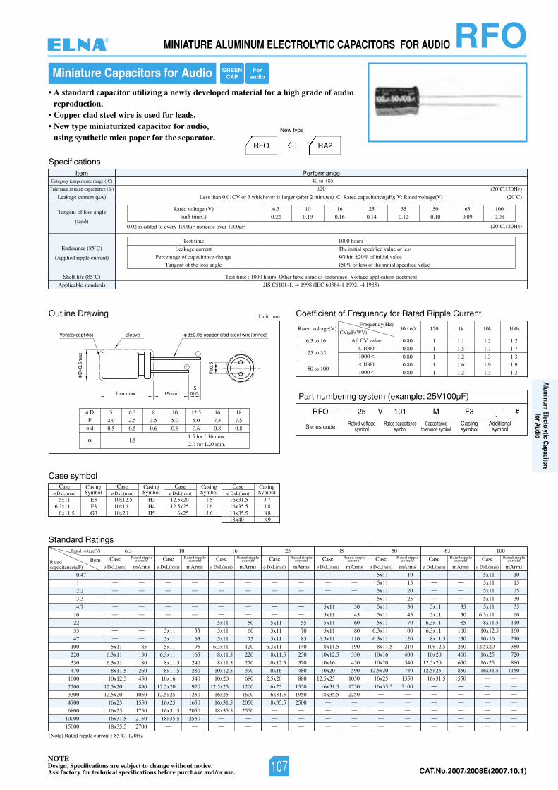
NOTEDesign, Specifications are subject to change without notice.Ask factory for technical specifications before purchase and/or use. CAT.No.2007/2008E(2007.10.1)
• A standard capacitor utilizing a newly developed material for a high grade of audioreproduction.
• Copper clad steel wire is used for leads.• New type miniaturized capacitor for audio,
using synthetic mica paper for the separator.RA2RFO
New type
RFOMINIATURE ALUMINUM ELECTROLYTIC CAPACITORS FOR AUDIO
Miniature Capacitors for Audio
Outline Drawing Unit: mm
L max. 15min.
SleeveVent(except 5)
D0.
5max
.
F0.
5
d 0.05 copper clad steel wire(tinned)
5min.
Coefficient of Frequency for Rated Ripple Current
Rated voltage(V)Frequency(Hz)
6.3 to 16
25 to 35
50 to 100
All CV value
1000
1000
1000
1000
50 . 60 120 1k 10k 100k
0.80 1 1.1 1.2 1.2
0.80 1 1.5 1.7 1.7
0.80 1 1.2 1.3 1.3
0.80 1 1.6 1.9 1.9
0.80 1 1.2 1.3 1.3
CV(µFxWV)
Standard Ratings
(Note) Rated ripple current : 85˚C, 120Hz
0.47
1
2.2
3.3
4.7
10
22
33
47
100
220
330
470
1000
2200
3300
4700
6800
10000
15000
Rated voltage(V) 6.3 10 16 25 35 50 63 100
ItemRatedcapacitance(µF)
— —
— —
— —
— —
— —
— —
— —
— —
— —
5x11 85
6.3x11 150
6.3x11 180
8x11.5 260
10x12.5 450
12.5x20 890
12.5x20 1050
16x25 1550
16x25 1750
16x31.5 2150
18x35.5 2700
Case
ø DxL(mm) mArms
Rated ripplecurrent Case
ø DxL(mm) mArms
Rated ripplecurrent Case
ø DxL(mm) mArms
Rated ripplecurrent Case
ø DxL(mm) mArms
Rated ripplecurrent Case
ø DxL(mm) mArms
Rated ripplecurrent Case
ø DxL(mm) mArms
Rated ripplecurrent Case
ø DxL(mm) mArms
Rated ripplecurrent Case
ø DxL(mm) mArms
Rated ripplecurrent
— —
— —
— —
— —
— —
— —
— —
5x11 55
5x11 65
5x11 95
6.3x11 165
8x11.5 240
8x11.5 280
10x16 540
12.5x20 970
12.5x25 1250
16x25 1650
16x31.5 2050
18x35.5 2550— —
— —
— —
— —
— —
— —
— —
5x11 50
5x11 60
5x11 75
6.3x11 120
8x11.5 220
8x11.5 270
10x12.5 390
10x20 680
12.5x25 1200
16x25 1600
16x31.5 2050
18x35.5 2550— —
— —
— —
— —
— —
— —
— —
— —
5x11 55
5x11 70
5x11 85
6.3x11 140
8x11.5 250
10x12.5 370
10x16 480
12.5x20 880
16x25 1550
16x31.5 1950
18x35.5 2500— —
— —
— —
— —
— —
— —
— —
5x11 30
5x11 45
5x11 60
5x11 80
6.3x11 110
8x11.5 190
10x12.5 330
10x16 450
10x20 590
12.5x25 1050
16x31.5 1750
18x35.5 2250— —
— —
— —
— —
— —
— —
— —
— —
5x11 35
5x11 50
6.3x11 85
6.3x11 100
8x11.5 150
10x12.5 260
10x20 460
12.5x20 650
12.5x25 850
16x31.5 1550— —
— —
— —
— —
— —
— —
5x11 10
5x11 15
5x11 20
5x11 25
5x11 30
5x11 45
5x11 70
6.3x11 100
6.3x11 120
8x11.5 210
10x16 400
10x20 540
12.5x20 740
16x25 1350
16x35.5 2100— —
— —
— —
— —
— —
5x11 10
5x11 15
5x11 25
5x11 30
5x11 35
6.3x11 60
8x11.5 110
10x12.5 160
10x16 210
12.5x20 380
16x25 720
16x25 880
16x31.5 1150— —
— —
— —
— —
— —
— —
— —
ø D
F
ø d
5 6.3 8 10 12.5 16 18
2.0 2.5 3.5 5.0 5.0 7.5 7.5
0.5 0.5 0.6 0.6 0.6 0.8 0.8
1.51.5 for L16 max.
2.0 for L20 min.
SpecificationsItem Performance
Category temperature range (˚C)
Tolerance at rated capacitance (%)
Leakage current (µA)
Tangent of loss angle
(tan )
Endurance (85˚C)
(Applied ripple current)
Shelf life (85˚C) Test time : 1000 hours. Other have same as endurance. Voltage application treatment
Applicable standards JIS C5101-1, -4 1998 (IEC 60384-1 1992, -4 1985)
40 to 85
20
02()V(egatlovdetaR:V;)Fµ(ecnaticapacdetaR:C)setunim2retfa(regralsirevehcihw3roVC10.0nahtsseL ˚C)
(20˚C,120Hz)
(20˚C,120Hz)
Test time
Leakage current
Percentage of capacitance change
Tangent of the loss angle
1000 hours
The initial specified value or less
Within 20% of initial value
150% or less of the initial specified value
0013605535261013.6)V(egatlovdetaR
0.22 0.19 0.16 0.14 0.12 0.10 0.09 0.08tan (max.)
0.02 is added to every 1000µF increase over 1000µF
Case symbolCase
ø DxL(mm)CasingSymbol
Caseø DxL(mm)
CasingSymbol
Caseø DxL(mm)
CasingSymbol
Caseø DxL(mm)
CasingSymbol
5x11 E36.3x11 F3
8x11.5 G3
10x12.5 H310x16 H410x20 H5
16x31.5 J 716x35.5 J 818x35.5 K818x40 K9
12.5x20 I 512.5x25 I 6
16x25 J 6
Part numbering system (example: 25V100µF)
RFO — V
Series code
25 101 M F3 #
Rated voltagesymbol
Rated capacitancesymbol
Capacitancetolerance symbol
Casingsymbol
Additionalsymbol
GREENCAP
Foraudio
®
107
Aluminum
Electolytic Capacitorsfor Audio
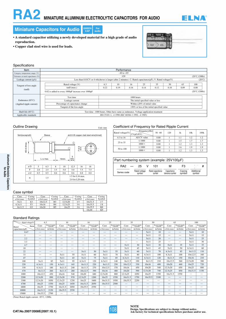
NOTEDesign, Specifications are subject to change without notice.Ask factory for technical specifications before purchase and/or use.CAT.No.2007/2008E(2007.10.1)
RA2 MINIATURE ALUMINUM ELECTROLYTIC CAPACITORS FOR AUDIO
Miniature Capacitors for Audio
• A standard capacitor utilizing a newly developed material for a high grade of audioreproduction.
• Copper clad steel wire is used for leads.
Outline Drawing Unit: mm
L max. 15min.
SleeveVent(except 5)
D0.
5max
.
F0.
5
d 0.05 copper clad steel wire(tinned)
5min.
Coefficient of Frequency for Rated Ripple Current
Rated voltage(V)Frequency(Hz)
6.3 to 16
25 to 35
50 to 100
All CV value
1000
1000
1000
1000
50 . 60 120 1k 10k 100k
0.80 1 1.1 1.2 1.2
0.80 1 1.5 1.7 1.7
0.80 1 1.2 1.3 1.3
0.80 1 1.6 1.9 1.9
0.80 1 1.2 1.3 1.3
CV(µFxWV)
Standard Ratings
(Note) Rated ripple current : 85˚C, 120Hz
0.47
1
2.2
3.3
4.7
10
22
33
47
100
220
330
470
1000
2200
3300
4700
6800
10000
15000
Rated voltage(V) 6.3 10 16 25 35 50 63 100
ItemRatedcapacitance(µF)
— —
— —
— —
— —
— —
— —
— —
— —
— —
5x11 85
6.3x11 150
6.3x11 180
8x11.5 260
10x12.5 450
12.5x20 890
12.5x20 1050
16x25 1550
16x25 1750
16x31.5 2150
18x35.5 2700
Case
ø DxL(mm) mArms
Rated ripplecurrent Case
ø DxL(mm) mArms
Rated ripplecurrent Case
ø DxL(mm) mArms
Rated ripplecurrent Case
ø DxL(mm) mArms
Rated ripplecurrent Case
ø DxL(mm) mArms
Rated ripplecurrent Case
ø DxL(mm) mArms
Rated ripplecurrent Case
ø DxL(mm) mArms
Rated ripplecurrent Case
ø DxL(mm) mArms
Rated ripplecurrent
— —
— —
— —
— —
— —
— —
— —
5x11 55
5x11 65
5x11 95
6.3x11 165
8x11.5 240
8x11.5 280
10x16 540
12.5x20 970
12.5x25 1250
16x25 1650
16x31.5 2050
18x35.5 2550— —
— —
— —
— —
— —
— —
— —
5x11 50
5x11 60
5x11 75
6.3x11 120
8x11.5 220
8x11.5 270
10x12.5 390
10x20 680
12.5x25 1200
16x25 1600
16x31.5 2050
18x35.5 2550— —
— —
— —
— —
— —
— —
— —
— —
5x11 55
5x11 70
5x11 85
6.3x11 140
8x11.5 250
10x12.5 370
10x16 480
12.5x20 880
16x25 1550
16x31.5 1950
18x35.5 2500— —
— —
— —
— —
— —
— —
— —
5x11 30
5x11 45
5x11 60
5x11 80
6.3x11 110
8x11.5 190
10x12.5 330
10x16 450
10x20 590
12.5x25 1050
16x31.5 1750
18x35.5 2250— —
— —
— —
— —
— —
— —
— —
— —
5x11 35
5x11 50
6.3x11 85
6.3x11 100
8x11.5 150
10x12.5 260
10x20 460
12.5x20 650
12.5x25 850
16x31.5 1550— —
— —
— —
— —
— —
— —
5x11 10
5x11 15
5x11 20
5x11 25
5x11 30
5x11 45
5x11 70
6.3x11 100
6.3x11 120
8x11.5 210
10x16 400
10x20 540
12.5x20 740
16x25 1350
16x35.5 2100— —
— —
— —
— —
— —
5x11 10
5x11 15
5x11 25
5x11 30
5x11 35
6.3x11 60
8x11.5 110
10x12.5 160
10x16 210
12.5x20 380
16x25 720
16x25 880
16x31.5 1150— —
— —
— —
— —
— —
— —
— —
ø D
F
ø d
5 6.3 8 10 12.5 16 18
2.0 2.5 3.5 5.0 5.0 7.5 7.5
0.5 0.5 0.6 0.6 0.6 0.8 0.8
1.51.5 for L16 max.
2.0 for L20 min.
SpecificationsItem Performance
Category temperature range (˚C)
Tolerance at rated capacitance (%)
Leakage current (µA)
Tangent of loss angle
(tan )
Endurance (85˚C)
(Applied ripple current)
Shelf life (85˚C) Test time : 1000 hours. Other have same as endurance. Voltage application treatment
Applicable standards JIS C5101-1, -4 1998 (IEC 60384-1 1992, -4 1985)
40 to 85
20
02()V(egatlovdetaR:V;)Fµ(ecnaticapacdetaR:C)setunim2retfa(regralsirevehcihw4roVC10.0nahtsseL ˚C)
(20˚C,120Hz)
(20˚C,120Hz)
Test time
Leakage current
Percentage of capacitance change
Tangent of the loss angle
1000 hours
The initial specified value or less
Within 20% of initial value
150% or less of the initial specified value
0013605535261013.6)V(egatlovdetaR
0.22 0.19 0.16 0.14 0.12 0.10 0.09 0.08tan (max.)
0.02 is added to every 1000µF increase over 1000µF
Case symbolCase
ø DxL(mm)CasingSymbol
Caseø DxL(mm)
CasingSymbol
Caseø DxL(mm)
CasingSymbol
Caseø DxL(mm)
CasingSymbol
5x11 E36.3x11 F3
8x11.5 G3
10x12.5 H310x16 H410x20 H5
16x31.5 J 716x35.5 J 818x35.5 K818x40 K9
12.5x20 I 512.5x25 I 6
16x25 J 6
Part numbering system (example: 25V100µF)
RA2 — V
Series code
25 101 M F3 #
Rated voltagesymbol
Rated capacitancesymbol
Capacitancetolerance symbol
Casingsymbol
Additionalsymbol
GREENCAP
Foraudio
®
108
Aluminum
Electolytic Capacitorsfor Audio
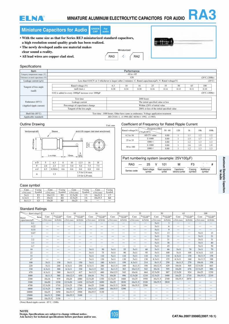
NOTEDesign, Specifications are subject to change without notice.Ask factory for technical specifications before purchase and/or use. CAT.No.2007/2008E(2007.10.1)
RA3MINIATURE ALUMINUM ELECTROLYTIC CAPACITORS FOR AUDIO
Miniature Capacitors for Audio
• With the same size as that for Series RE3 miniaturized standard capacitors,a high resolution sound quality grade has been realized.
• The newly developed audio use material makes clear sound a reality.
• All lead wires are copper clad steel.
Outline Drawing Unit: mm
L max. 15min.
SleeveVent(except 5)
D0.
5max
.
F0.
5
d 0.05 copper clad steel wire(tinned)
5min.
Coefficient of Frequency for Rated Ripple Current
Rated voltage(V)Frequency(Hz)
6.3 to 16
25 to 35
50 to 100
All CV value
1000
1000
1000
1000
50 . 60 120 1k 10k 100k
0.80 1 1.1 1.2 1.2
0.80 1 1.5 1.7 1.7
0.80 1 1.2 1.3 1.3
0.80 1 1.6 1.9 1.9
0.80 1 1.2 1.3 1.3
CV(µFxWV)
Standard Ratings
(Note) Rated ripple current : 85˚C, 120Hz
0.1
0.22
0.33
0.47
1
2.2
3.3
4.7
10
22
33
47
100
220
330
470
1000
2200
3300
4700
6800
10000
15000
22000
Rated voltage(V) 6.3 10 16 25 35 50 63 100
ItemRatedcapacitance(µF)
— —
— —
— —
— —
— —
— —
— —
— —
— —
— —
— —
— —
5x11 130
5x11 240
6.3x11 300
6.3x11 380
8x11.5 580
10x16 939
16x20 1230
12.5x20 1710
12.5x25 1930
16x25 2450
16x31.5 2580
18x35.5 3150
Case
ø DxL(mm) mArms
Rated ripplecurrent Case
ø DxL(mm) mArms
Rated ripplecurrent Case
ø DxL(mm) mArms
Rated ripplecurrent Case
ø DxL(mm) mArms
Rated ripplecurrent Case
ø DxL(mm) mArms
Rated ripplecurrent Case
ø DxL(mm) mArms
Rated ripplecurrent Case
ø DxL(mm) mArms
Rated ripplecurrent Case
ø DxL(mm) mArms
Rated ripplecurrent
— —
— —
— —
— —
— —
— —
— —
— —
— —
— —
— —
— —
5x11 150
6.3x11 250
6.3x11 330
8x11.5 417
10x12.5 650
10x20 1080
12.5x20 1430
12.5x25 1780
16x25 2270
16x31.5 2500
18x35.5 3100— —
— —
— —
— —
— —
— —
— —
— —
— —
5x11 50
5x11 75
5x11 110
5x11 130
5x11 180
6.3x11 280
8x11.5 383
8x11.5 480
10x16 791
12.5x20 1350
12.5x25 1690
16x25 2100
16x31.5 2480
18x35.5 3130— —
— —
— —
— —
— —
— —
— —
— —
— —
— —
5x11 55
5x11 90
5x11 110
5x11 130
6.3x11 199
8x11.5 349
8x11.5 383
10x12.5 545
10x20 996
12.5x25 1660
16x25 2030
16x31.5 2650
18x35.5 3290— —
— —
— —
— —
— —
— —
— —
— —
— —
— —
— —
5x11 60
5x11 95
5x11 110
5x11 130
6.3x11 214
8x11.5 350
10x12.5 542
10x16 664
12.5x20 1210
16x25 1950
16x31.5 2320
18x35.5 2290— —
— —
— —
— —
— —
— —
— —
— —
— —
— —
— —
— —
5x11 70
5x11 105
6.3x11 130
6.3x11 160
8x11.5 270
10x16 505
10x20 676
12.5x20 924
16x25 1710
18x35.5 2870— —
— —
— —
— —
— —
— —
5x11 3
5x11 6
5x11 9
5x11 13
5x11 21
5x11 31
5x11 38
5x11 45
5x11 66
5x11 100
5x11 110
6.3x11 155
8x11.5 250
10x12.5 429
10x16 595
12.5x20 887
12.5x25 1400
16x31.5 2340
18x35.5 2810— —
— —
— —
— —
— —
— —
— —
— —
5x11 13
5x11 21
5x11 31
5x11 40
5x11 50
5x11 70
6.3x11 115
8x11.5 158
8x11.5 188
10x16 358
12.5x20 663
12.5x25 886
16x25 1230
18x35.5 2210— —
— —
— —
— —
— —
— —
— —
ø D
F
ø d
5 6.3 8 10 12.5 16 18
2.0 2.5 3.5 5.0 5.0 7.5 7.5
0.5 0.5/0.6 0.6 0.6 0.6 0.8 0.8
1.51.5 for L16 max.
2.0 for L20 min.
SpecificationsItem Performance
Category temperature range (˚C)
Tolerance at rated capacitance (%)
Leakage current (µA)
Tangent of loss angle
(tan )
Endurance (85˚C)
(Applied ripple current)
Shelf life (85˚C) Test time : 1000 hours. Other have same as endurance. Voltage application treatment
Applicable standards JIS C5101-1, -4 1998 (IEC 60384-1 1992, -4 1985)
40 to 85
20
02()V(egatlovdetaR:V;)Fµ(ecnaticapacdetaR:C)setunim2retfa(regralsirevehcihw3roVC10.0nahtsseL ˚C)
(20˚C,120Hz)
(20˚C,120Hz)
Test time
Leakage current
Percentage of capacitance change
Tangent of the loss angle
2000 hours
The initial specified value or less
Within 20% of initial value
200% or less of the initial specified value
0013605535261013.6)V(egatlovdetaR
0.28 0.24 0.20 0.16 0.14 0.12 0.11 0.10tan (max.)
0.02 is added to every 1000µF increase over 1000µF
Case symbolCase
ø DxL(mm)CasingSymbol
Caseø DxL(mm)
CasingSymbol
Caseø DxL(mm)
CasingSymbol
Caseø DxL(mm)
CasingSymbol
5x11 E36.3x11 F3
8x11.5 G3
10x12.5 H310x16 H410x20 H5
16x31.5 J 718x35.5 K8
12.5x20 I 512.5x25 I 6
16x25 J 6
RA3 RA2
Miniaturized
Part numbering system (example: 25V100µF)
RA3 —
— —
V
Series code
25 101 M F3 #
Rated voltagesymbol
Rated capacitancesymbol
Capacitancetolerance symbol
Casingsymbol
Additionalsymbol
GREENCAP
Foraudio
®
109
Aluminum
Electolytic Capacitorsfor Audio
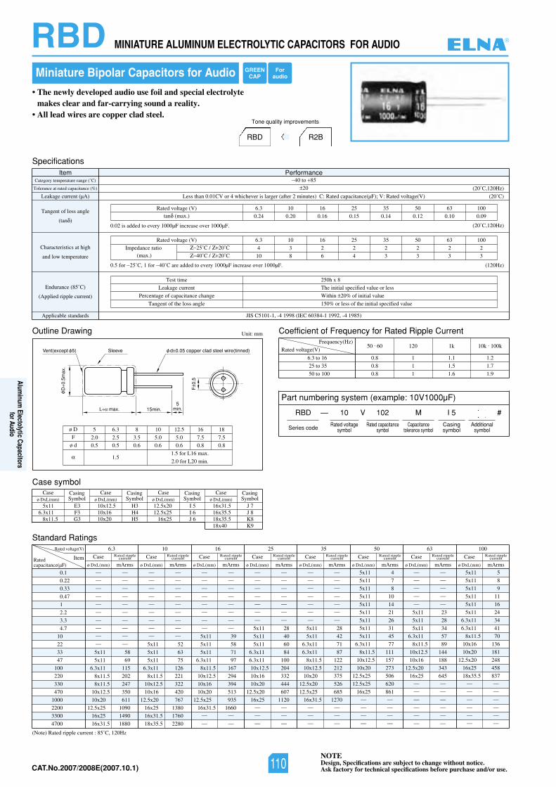
NOTEDesign, Specifications are subject to change without notice.Ask factory for technical specifications before purchase and/or use.CAT.No.2007/2008E(2007.10.1)
• The newly developed audio use foil and special electrolytemakes clear and far-carrying sound a reality.
• All lead wires are copper clad steel.
RBD R2B
Tone quality improvements
RBD MINIATURE ALUMINUM ELECTROLYTIC CAPACITORS FOR AUDIO
Miniature Bipolar Capacitors for Audio
Outline Drawing Unit: mm
L max. 15min.
SleeveVent(except 5)
D0.
5max
.
F0.
5
d 0.05 copper clad steel wire(tinned)
5min.
Standard Ratings
(Note) Rated ripple current : 85˚C, 120Hz
0.1
0.22
0.33
0.47
1
2.2
3.3
4.7
10
22
33
47
100
220
330
470
1000
2200
3300
4700
Rated voltage(V) 6.3 10 16 25 35 50 63 100
ItemRatedcapacitance(µF)
— —
— —
— —
— —
— —
— —
— —
— —
— —
— —
5x11 58
5x11 69
6.3x11 115
8x11.5 202
8x11.5 247
10x12.5 350
10x20 611
12.5x25 1090
16x25 1490
16x31.5 1880
Case
ø DxL(mm) mArms
Rated ripplecurrent Case
ø DxL(mm) mArms
Rated ripplecurrent Case
ø DxL(mm) mArms
Rated ripplecurrent Case
ø DxL(mm) mArms
Rated ripplecurrent Case
ø DxL(mm) mArms
Rated ripplecurrent Case
ø DxL(mm) mArms
Rated ripplecurrent Case
ø DxL(mm) mArms
Rated ripplecurrent Case
ø DxL(mm) mArms
Rated ripplecurrent
— —
— —
— —
— —
— —
— —
— —
— —
— —
5x11 52
5x11 63
5x11 75
6.3x11 126
8x11.5 221
10x12.5 322
10x16 420
12.5x20 767
16x25 1380
16x31.5 1760
18x35.5 2280
— —
— —
— —
— —
— —
— —
— —
— —
5x11 39
5x11 58
5x11 71
6.3x11 97
8x11.5 167
10x12.5 294
10x16 394
10x20 513
12.5x25 935
16x31.5 1660— —
— —
— —
— —
— —
— —
— —
— —
— —
5x11 28
5x11 40
5x11 60
6.3x11 84
6.3x11 100
10x12.5 204
10x16 332
10x20 444
12.5x20 607
16x25 1120— —
— —
— —
— —
— —
— —
— —
— —
— —
— —
5x11 28
5x11 42
6.3x11 71
6.3x11 87
8x11.5 122
10x12.5 212
10x20 375
12.5x20 526
12.5x25 685
16x31.5 1270— —
— —
— —
— —
— —
— —
— —
— —
5x11 23
5x11 28
5x11 34
6.3x11 57
8x11.5 89
10x12.5 144
10x16 188
12.5x20 343
16x25 645— —
— —
— —
— —
— —
— —
5x11 4
5x11 7
5x11 8
5x11 10
5x11 14
5x11 21
5x11 26
5x11 31
5x11 45
6.3x11 77
8x11.5 111
10x12.5 157
10x20 273
12.5x25 506
12.5x25 620
16x25 861— —
— —
— —
— —
5x11 5
5x11 8
5x11 9
5x11 11
5x11 16
5x11 24
6.3x11 34
6.3x11 41
8x11.5 70
10x16 136
10x20 181
12.5x20 248
16x25 458
18x35.5 837— —
— —
— —
— —
— —
— —
ø D
F
ø d
5 6.3 8 10 12.5 16 18
2.0 2.5 3.5 5.0 5.0 7.5 7.5
0.5 0.5 0.6 0.6 0.6 0.8 0.8
1.51.5 for L16 max.
2.0 for L20 min.
SpecificationsItem Performance
Category temperature range (˚C)
Tolerance at rated capacitance (%)
Leakage current (µA)
Tangent of loss angle
(tan )
Endurance (85˚C)
(Applied ripple current)
Applicable standards JIS C5101-1, -4 1998 (IEC 60384-1 1992, -4 1985)
40 to 85
20
02()V(egatlovdetaR:V;)Fµ(ecnaticapacdetaR:C)setunim2retfa(regralsirevehcihw4roVC10.0nahtsseL ˚C)
(20˚C,120Hz)
(20˚C,120Hz)
Test time
Leakage current
Percentage of capacitance change
Tangent of the loss angle
250h x 8
The initial specified value or less
Within 20% of initial value
150% or less of the initial specified value
0013605535261013.6)V(egatlovdetaR
0.24 0.20 0.16 0.15 0.14 0.12 0.10 0.09tan (max.)
0.02 is added to every 1000µF increase over 1000µF.
0.5 for 25˚C, 1 for 40˚C are added to every 1000µF increase over 1000µF.
Characteristics at high
and low temperature
(120Hz)
0013605535261013.6)V(egatlovdetaR
4 3 2 2 2 2 2 2
10 8 6 4 3 3 3 3
Impedance ratio(max.)
25˚C / 20˚C
40˚C / 20˚C
Coefficient of Frequency for Rated Ripple Current
Rated voltage(V)
Frequency(Hz)
6.3 to 16
25 to 35
50 to 100
50 . 60 120 1k 10k . 100k
0.8 1 1.1 1.2
0.8 1 1.5 1.7
0.8 1 1.6 1.9
Case symbolCase
ø DxL(mm)CasingSymbol
Caseø DxL(mm)
CasingSymbol
Caseø DxL(mm)
CasingSymbol
Caseø DxL(mm)
CasingSymbol
5x11 E36.3x11 F3
8x11.5 G3
10x12.5 H310x16 H410x20 H5
16x31.5 J 716x35.5 J 818x35.5 K818x40 K9
12.5x20 I 512.5x25 I 6
16x25 J 6
Part numbering system (example: 10V1000µF)
RBD — V
Series code
10 102 M I 5 #
Rated voltagesymbol
Rated capacitancesymbol
Capacitancetolerance symbol
Casingsymbol
Additionalsymbol
GREENCAP
Foraudio
®
110
Aluminum
Electolytic Capacitorsfor Audio
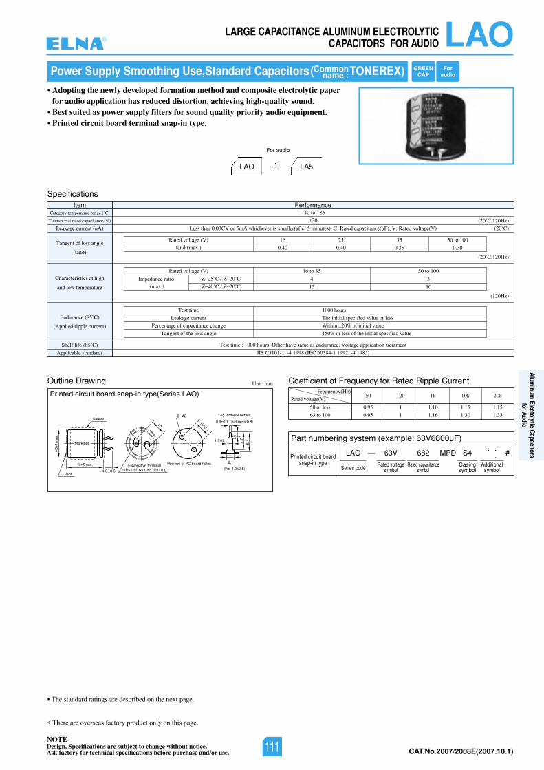
NOTEDesign, Specifications are subject to change without notice.Ask factory for technical specifications before purchase and/or use. CAT.No.2007/2008E(2007.10.1)
LAOLARGE CAPACITANCE ALUMINUM ELECTROLYTICCAPACITORS FOR AUDIO
• The standard ratings are described on the next page.
There are overseas factory product only on this page.
Power Supply Smoothing Use,Standard Capacitors( TONEREX)
• Adopting the newly developed formation method and composite electrolytic paperfor audio application has reduced distortion, achieving high-quality sound.
• Best suited as power supply filters for sound quality priority audio equipment.• Printed circuit board terminal snap-in type.
LAO LA5
For audio
Outline Drawing Unit: mm
L 2max.
D1m
ax.
Sleeve
Vent
1.5 0.1
4.0 0.5
Position of PC board holes(–)Negative terminalindicated by cross notching
2.1
5.44.7
100.1
10
2– 2
Markings
0.9
Lug terminal details
0.9 0.1 Thickness:0.8t
(For 4.0 0.5)
SpecificationsItem Performance
Category temperature range (˚C)
Tolerance at rated capacitance (%)
Leakage current (µA)
Tangent of loss angle
(tan )
Endurance (85˚C)
(Applied ripple current)
Applicable standards JIS C5101-1, -4 1998 (IEC 60384-1 1992, -4 1985)Shelf life (85˚C) Test time : 1000 hours. Other have same as endurance. Voltage application treatment
40 to 85
20
02()V(egatlovdetaR:V,)Fµ(ecnaticapacdetaR:C)setunim5retfa(rellamssirevehcihwAm5roVC30.0nahtsseL ˚C)
(20˚C,120Hz)
(20˚C,120Hz)
Test time
Leakage current
Percentage of capacitance change
Tangent of the loss angle
1000 hours
The initial specified value or less
Within 20% of initial value
150% or less of the initial specified value
Characteristics at high
and low temperature
(120Hz)
001ot0553ot61)V(egatlovdetaR
34
0151
Impedance ratio(max.)
25˚C / 20˚C
40˚C / 20˚C
Part numbering system (example: 63V6800µF)
Commonname :
Printed circuit board snap-in type(Series LAO)
Printed circuit boardsnap-in type
Coefficient of Frequency for Rated Ripple Current
Rated voltage(V)
Frequency(Hz)
50 or less
63 to 100
50 120 1k 10k 20k
0.95 1 1.10 1.15 1.15
0.95 1 1.16 1.30 1.33
LAO —
Series code
63V 682 S4 #MPD
Rated voltagesymbol
Rated capacitancesymbol
Additionalsymbol
Casingsymbol
001ot05535261)V(egatlovdetaR
0.40 0.40 0.35 0.30tan (max.)
GREENCAP
Foraudio
®
111
Aluminum
Electolytic Capacitorsfor Audio
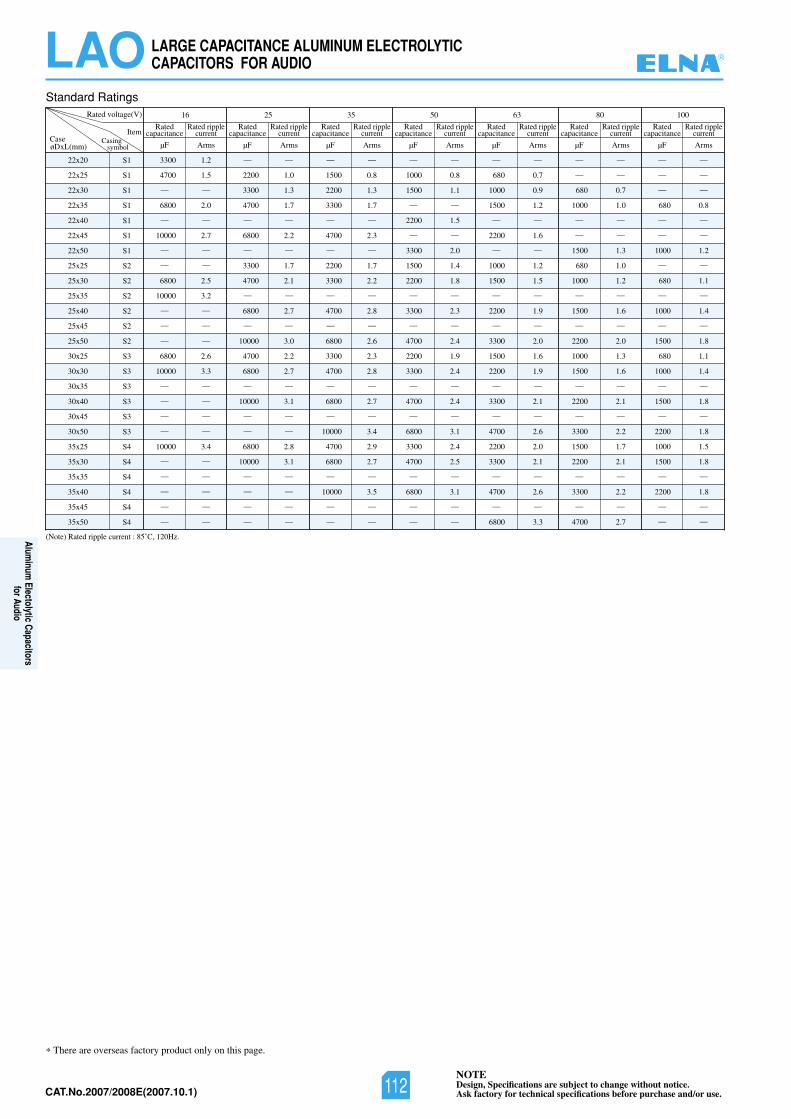
NOTEDesign, Specifications are subject to change without notice.Ask factory for technical specifications before purchase and/or use.CAT.No.2007/2008E(2007.10.1)
LAO LARGE CAPACITANCE ALUMINUM ELECTROLYTICCAPACITORS FOR AUDIO
There are overseas factory product only on this page.
Standard Ratings
22x20
22x25
22x30
22x35
22x40
22x45
22x50
25x25
25x30
25x35
25x40
25x45
25x50
30x25
30x30
30x35
30x40
30x45
30x50
35x25
35x30
35x35
35x40
35x45
35x50
S1
S1
S1
S1
S1
S1
S1
S2
S2
S2
S2
S2
S2
S3
S3
S3
S3
S3
S3
S4
S4
S4
S4
S4
S4
Rated voltage(V) 16 25 35 50 63 80 100
Item
øD xL(mm)
3300 1.2
4700 1.5
— —
6800 2.0
— —
10000 2.7
— —
— —
6800 2.5
10000 3.2
— —
— —
— —
6800 2.6
10000 3.3
— —
— —
— —
— —
10000 3.4
— —
— —
— —
— —
— —
— —
2200 1.0
3300 1.3
4700 1.7
— —
6800 2.2
— —
3300 1.7
4700 2.1
— —
6800 2.7
— —
10000 3.0
4700 2.2
6800 2.7
— —
10000 3.1
— —
— —
6800 2.8
10000 3.1
— —
— —
— —
— —
— —
1500 0.8
2200 1.3
3300 1.7
— —
4700 2.3
— —
2200 1.7
3300 2.2
— —
4700 2.8
— —
6800 2.6
3300 2.3
4700 2.8
— —
6800 2.7
— —
10000 3.4
4700 2.9
6800 2.7
— —
10000 3.5
— —
— —
— —
1000 0.8
1500 1.1
— —
2200 1.5
— —
3300 2.0
1500 1.4
2200 1.8
— —
3300 2.3
— —
4700 2.4
2200 1.9
3300 2.4
— —
4700 2.4
— —
6800 3.1
3300 2.4
4700 2.5
— —
6800 3.1
— —
— —
— —
680 0.7
1000 0.9
1500 1.2
— —
2200 1.6
— —
1000 1.2
1500 1.5
— —
2200 1.9
— —
3300 2.0
1500 1.6
2200 1.9
— —
3300 2.1
— —
4700 2.6
2200 2.0
3300 2.1
— —
4700 2.6
— —
6800 3.3
— —
— —
680 0.7
1000 1.0
— —
— —
1500 1.3
680 1.0
1000 1.2
— —
1500 1.6
— —
2200 2.0
1000 1.3
1500 1.6
— —
2200 2.1
— —
3300 2.2
1500 1.7
2200 2.1
— —
3300 2.2
— —
4700 2.7
— —
— —
— —
680 0.8
— —
— —
1000 1.2
— —
680 1.1
— —
1000 1.4
— —
1500 1.8
680 1.1
1000 1.4
— —
1500 1.8
— —
2200 1.8
1000 1.5
1500 1.8
— —
2200 1.8
— —
— —
µF ArmsCasing
symbol
Ratedcapacitance
Rated ripplecurrent
µF Arms
Ratedcapacitance
Rated ripplecurrent
µF Arms
Ratedcapacitance
Rated ripplecurrent
µF Arms
Ratedcapacitance
Rated ripplecurrent
µF Arms
Ratedcapacitance
Rated ripplecurrent
µF Arms
Ratedcapacitance
Rated ripplecurrent
µF Arms
Ratedcapacitance
Rated ripplecurrent
(Note) Rated ripple current : 85˚C, 120Hz.
Case
®
112
Aluminum
Electolytic Capacitorsfor Audio
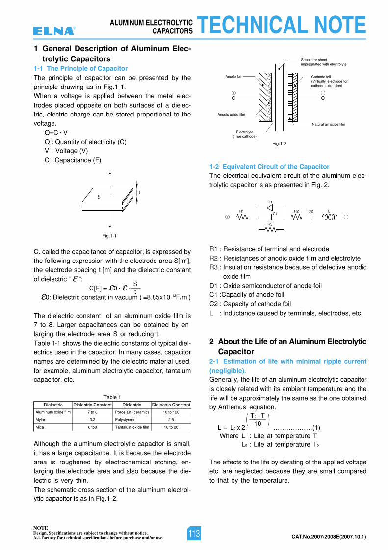
NOTEDesign, Specifications are subject to change without notice.Ask factory for technical specifications before purchase and/or use. CAT.No.2007/2008E(2007.10.1)
ALUMINUM ELECTROLYTICCAPACITORS TECHNICAL NOTE
1 General Description of Aluminum Elec-trolytic Capacitors
1-1 The Principle of CapacitorThe principle of capacitor can be presented by theprinciple drawing as in Fig.1-1.When a voltage is applied between the metal elec-trodes placed opposite on both surfaces of a dielec-tric, electric charge can be stored proportional to thevoltage.
Q=C • VQ : Quantity of electricity (C)V : Voltage (V)C : Capacitance (F)
C. called the capacitance of capacitor, is expressed bythe following expression with the electrode area S[m2],the electrode spacing t [m] and the dielectric constantof dielectric “ ”:
C[F] = 0 • •
0: Dielectric constant in vacuum ( =8.85x10 12F/m )
The dielectric constant of an aluminum oxide film is7 to 8. Larger capacitances can be obtained by en-larging the electrode area S or reducing t.Table 1-1 shows the dielectric constants of typical diel-ectrics used in the capacitor. In many cases, capacitornames are determined by the dielectric material used,for example, aluminum electrolytic capacitor, tantalumcapacitor, etc.
Although the aluminum electrolytic capacitor is small,it has a large capacitance. It is because the electrodearea is roughened by electrochemical etching, en-larging the electrode area and also because the die-lectric is very thin.The schematic cross section of the aluminum electrol-ytic capacitor is as in Fig.1-2.
1-2 Equivalent Circuit of the CapacitorThe electrical equivalent circuit of the aluminum elec-trolytic capacitor is as presented in Fig. 2.
R1 : Resistance of terminal and electrodeR2 : Resistances of anodic oxide film and electrolyteR3 : Insulation resistance because of defective anodic
oxide filmD1 : Oxide semiconductor of anode foilC1 :Capacity of anode foilC2 : Capacity of cathode foil L : Inductance caused by terminals, electrodes, etc.
2 About the Life of an Aluminum ElectrolyticCapacitor
2-1 Estimation of life with minimal ripple current(negligible).Generally, the life of an aluminum electrolytic capacitoris closely related with its ambient temperature and thelife will be approximately the same as the one obtainedby Arrhenius’ equation.
The effects to the life by derating of the applied voltageetc. are neglected because they are small comparedto that by the temperature.
Fig.1-1
tS
S——
t
Anodic oxide film
Anode foil
Electrolyte(True cathode)
Fig.1-2
Natural air oxide film
Cathode foil(Virtually, electrode forcathode extraction)
Separator sheetimpregnated with electrolyte
L2C2R1RC1
D1
R3
L = L0 x 2 ………………(1)Where L : Life at temperature T
L0 : Life at temperature T0
T0 T———10 ))
Aluminum oxide film
Mylar
Mica
7 to 8
3.2
6 to8
Porcelain (ceramic)
Polystyrene
Tantalum oxide film
10 to 120
2.5
10 to 20
Table 1Dielectric Dielectric Constant Dielectric Dielectric Constant
®
113
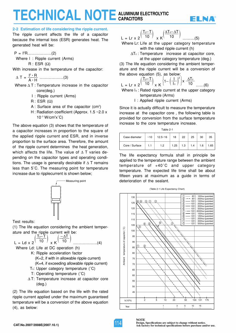
NOTEDesign, Specifications are subject to change without notice.Ask factory for technical specifications before purchase and/or use.CAT.No.2007/2008E(2007.10.1)
ALUMINUM ELECTROLYTICCAPACITORSTECHNICAL NOTE
2-2 Estimation of life considering the ripple current.The ripple current affects the life of a capacitorbecause the internal loss (ESR) generates heat. Thegenerated heat will be:
P = I2R………………(2)Where l : Ripple current (Arms)
R : ESR ( )With increase in the temperature of the capacitor:
T = ………………(3)
Where T : Temperature increase in the capacitorcore(deg.)
I : Ripple current (Arms) R : ESR ( )A : Surface area of the capacitor (cm2) H : Radiation coefficient (Approx. 1.5 ~2.0 x
10 3 W/cm2x˚C)
The above equation (3) shows that the temperature ofa capacitor increases in proportion to the square ofthe applied ripple current and ESR, and in inverseproportion to the surface area. Therefore, the amountof the ripple current determines the heat generation,which affects the life. The value of T varies de-pending on the capacitor types and operating condi-tions. The usage is generally desirable if T remainsless than 5˚C. The measuring point for temperatureincrease due to ripplecurrent is shown below;
Test results:(1) The life equation considering the ambient temper-ature and the ripple current will be:
L = Ld x 2 x K ………………(4)Where Ld: Life at DC operation (h)
K: Ripple acceleration factor(K=2, if with in allowable ripple current)(K=4, if exceeding allowable ripple current)
T0: Upper category temperature (˚C)T: Operating temperature (˚C)T: Temperature increase at capacitor core
(deg.)
(2) The life equation based on the life with the ratedripple current applied under the maximum guaranteedtemperature will be a conversion of the above equation(4), as below:
L = Lr x 2 x K ………(5)Where Lr: Life at the upper category temperature
with the rated ripple current (h)T0 : Temperature increase at capacitor core,
at the upper category temperature (deg.)(3) The life equation considering the ambient temper-ature and the ripple current will be a conversion ofthe above equation (5), as below:
L = Lr x 2 x K ……(6)Where l 0 : Rated ripple current at the upper category
temperature (Arms)I : Applied ripple current (Arms)
Since it is actually difficult to measure the temperatureincrease at the capacitor core , the following table isprovided for conversion from the surface temperatureincrease to the core temperature increase.
The life expectancy formula shall in principle beapplied to the temperature range between the ambienttemperature of +40˚C and upper categorytemperature. The expected life time shall be aboutfifteen years at maximum as a guide in terms ofdeterioration of the sealant.
45
2
50
55
60
65
70
75
80
85
90
95
100
105
110
115
120
125
130
5 10
1
Am
bien
t te
mpe
ratu
re o
f cap
acito
r (˚
C)
Year
h(103h) 20 50 100 131 175
3 15105
(Table 2-1 Life Expectancy Chart)
85˚C: 1000hour guaranteed1
1
2
2
3
3
4
4
5
5
6
6
7
7
8
8
9
9
10
10
12
12
11
1185˚C: 2000hour guaranteed
105˚C: 1000hour guaranteed105˚C: 2000hour guaranteed105˚C: 3000hour guaranteed105˚C: 5000hour guaranteed105˚C: 20000hour guaranteed125˚C: 1000hour guaranteed125˚C: 1250hour guaranteed125˚C: 2000hour guaranteed125˚C: 3000hour guaranteed125˚C: 5000hour guaranteed
Measuring point
I2 • R———A • H
T0 T———10 )) T———
10 ))
T0 T———10 )) T0 T————
10 ))
T0 T———10 )) I
1 ——I 0
T0x ———10)2)
Table 2-1
Case diameter
Core / Surface
~10 12.5~16 18 22 25 30 35
1.1 1.2 1.25 1.3 1.4 1.6 1.65
®
114
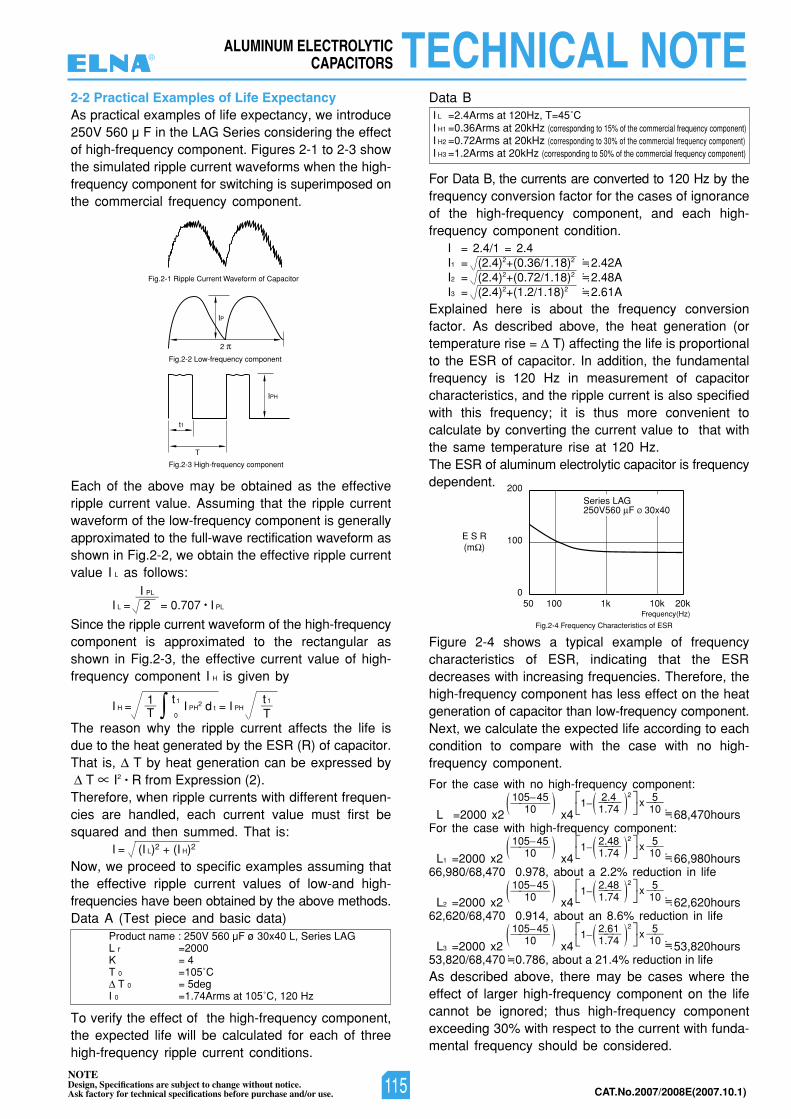
NOTEDesign, Specifications are subject to change without notice.Ask factory for technical specifications before purchase and/or use. CAT.No.2007/2008E(2007.10.1)
ALUMINUM ELECTROLYTICCAPACITORS TECHNICAL NOTE
2-2 Practical Examples of Life ExpectancyAs practical examples of life expectancy, we introduce250V 560 µ F in the LAG Series considering the effectof high-frequency component. Figures 2-1 to 2-3 showthe simulated ripple current waveforms when the high-frequency component for switching is superimposed onthe commercial frequency component.
Each of the above may be obtained as the effectiveripple current value. Assuming that the ripple currentwaveform of the low-frequency component is generallyapproximated to the full-wave rectification waveform asshown in Fig.2-2, we obtain the effective ripple currentvalue I L as follows:
Since the ripple current waveform of the high-frequencycomponent is approximated to the rectangular asshown in Fig.2-3, the effective current value of high-frequency component I H is given by
The reason why the ripple current affects the life isdue to the heat generated by the ESR (R) of capacitor.That is, T by heat generation can be expressed by
T I2 • R from Expression (2).Therefore, when ripple currents with different frequen-cies are handled, each current value must first besquared and then summed. That is:
Now, we proceed to specific examples assuming thatthe effective ripple current values of low-and high-frequencies have been obtained by the above methods.Data A (Test piece and basic data)
To verify the effect of the high-frequency component,the expected life will be calculated for each of threehigh-frequency ripple current conditions.
Data B
For Data B, the currents are converted to 120 Hz by thefrequency conversion factor for the cases of ignoranceof the high-frequency component, and each high-frequency component condition.
I = 2.4/1 = 2.4I1 = (2.4)2+(0.36/1.18)2 2.42AI2 = (2.4)2+(0.72/1.18)2 2.48AI3 = (2.4)2+(1.2/1.18)2 2.61A
Explained here is about the frequency conversionfactor. As described above, the heat generation (ortemperature rise = T) affecting the life is proportionalto the ESR of capacitor. In addition, the fundamentalfrequency is 120 Hz in measurement of capacitorcharacteristics, and the ripple current is also specifiedwith this frequency; it is thus more convenient tocalculate by converting the current value to that withthe same temperature rise at 120 Hz.The ESR of aluminum electrolytic capacitor is frequencydependent.
Figure 2-4 shows a typical example of frequencycharacteristics of ESR, indicating that the ESRdecreases with increasing frequencies. Therefore, thehigh-frequency component has less effect on the heatgeneration of capacitor than low-frequency component.Next, we calculate the expected life according to eachcondition to compare with the case with no high-frequency component.
For the case with no high-frequency component:
L =2000 x2 x4 68,470hoursFor the case with high-frequency component:
L1 =2000 x2 x4 66,980hours66,980/68,470 0.978, about a 2.2% reduction in life
L2 =2000 x2 x4 62,620hours62,620/68,470 0.914, about an 8.6% reduction in life
L3 =2000 x2 x4 53,820hours53,820/68,470 0.786, about a 21.4% reduction in lifeAs described above, there may be cases where theeffect of larger high-frequency component on the lifecannot be ignored; thus high-frequency componentexceeding 30% with respect to the current with funda-mental frequency should be considered.
Product name : 250V 560 µF ø 30x40 L, Series LAGL r =2000K = 4T 0 =105˚C
T 0 = 5degI 0 =1.74Arms at 105˚C, 120 Hz
T
t1
IPH
2
IP
Fig.2-3 High-frequency component
Fig.2-2 Low-frequency component
Fig.2-1 Ripple Current Waveform of Capacitor
200
100E S R(m )
050 100 1k 10k 20k
Fig.2-4 Frequency Characteristics of ESR
Frequency(Hz)
Series LAG250V560 F Ø 30x40
I L =2.4Arms at 120Hz, T=45˚CI H1 =0.36Arms at 20kHz (corresponding to 15% of the commercial frequency component)I H2 =0.72Arms at 20kHz (corresponding to 30% of the commercial frequency component)I H3 =1.2Arms at 20kHz (corresponding to 50% of the commercial frequency component)
•=•
I L = 2 = 0.707 • I PL
I PL——
I H = I PH2 d t = I PH
I = (I L)2 + (I H)2
1—T
t1
0
t 1—T
105 45————10 )) 2.41 ———
1.745x ——10)2)
•=•
105 45————10 )) 2.481 ———
1.745x ——10)2)
•=•
105 45————10 )) 2.481 ———
1.745x ——10)2)
•=•
•=••=••=•
105 45————10 )) 2.611 ———
1.745x ——10)2)
•=•
®
115
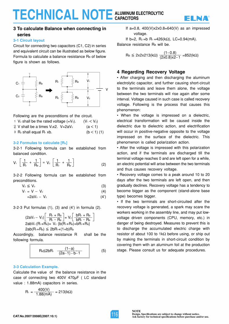
NOTEDesign, Specifications are subject to change without notice.Ask factory for technical specifications before purchase and/or use.CAT.No.2007/2008E(2007.10.1)
ALUMINUM ELECTROLYTICCAPACITORSTECHNICAL NOTE
3 To calculate Balance when connecting inseries
3-1 Circuit layout Circuit for connecting two capacitors (C1, C2) in seriesand equivalent circuit can be illustrated as below figure.Formula to calculate a balance resistance RB of belowfigure is shown as follows.
Following are the preconditions of the circuit.V2 shall be the rated voltage (=V0). (V1 V2)V shall be a times V0x2. V=2aV0 (a 1)R2 shall equal R1 xb. (b 1) (1)
3-2 Formulas to calculate [RB]3-2-1 Following formula can be established frombalanced condition.
(2)
3-2-2 Following formula can be established frompreconditions.
V2 V0 (3)V1 = V V2 (4)
=2aV0 V2 (4’)
3-2-3 Put formulas (1), (3) and (4’) in formula (2).
2abV0 (R1+RB)= V2 {b(R1+RB)+bR1+RB}2ab(R1+RB) 2bR1+(1+b)RB
Accordingly, balance resistance R shall be thefollowing formula.
(5)
3-3 Calculation Example.Calculate the value of the balance resistance in thecase of connecting two 400V 470µF ( LC standardvalue : 1.88mA) capacitors in series.
If a=0.8, 400(V)x2x0.8=640(V) as an impressedvoltage.
If b=2, R2 =b R1 =426(k ), LC=0.94(mA).Balance resistance RB will be.
RB 2x2x213(k ) =852(k )
4 Regarding Recovery Voltage• After charging and then discharging the aluminumelectrolytic capacitor, and further causing short-circuitto the terminals and leave them alone, the voltagebetween the two terminals will rise again after someinterval. Voltage caused in such case is called recoveryvoltage. Following is the process that causes thisphenomenon:• When the voltage is impressed on a dielectric,electrical transformation will be caused inside thedielectric due to dielectric action, and electrificationwill occur in positive-negative opposite to the voltageimpressed on the surface of the dielectric. Thisphenomenon is called polarization action.• After the voltage is impressed with this polarizationaction, and if the terminals are discharged till theterminal voltage reaches 0 and are left open for a while,an electric potential will arise between the two terminalsand thus causes recovery voltage.• Recovery voltage comes to a peak around 10 to 20days after the two terminals are left open, and thengradually declines. Recovery voltage has a tendency tobecome bigger as the component (stand-alone basetype) becomes bigger.• If the two terminals are short-circuited after therecovery voltage is generated, a spark may scare theworkers working in the assembly line, and may put low-voltage driven components (CPU, memory, etc.) indanger of being destroyed. Measures to prevent this isto discharge the accumulated electric charge withresistor of about 100 to 1k before using, or ship outby making the terminals in short-circuit condition bycovering them with an aluminum foil at the productionstage. Please consult us for adequate procedures.
1
2
3
(1 a)RB 2bR1 ——————————
(2a 1) • b 1
400(V)R1 = ———————— = 213(k )
1.88(mA)
R1 + RB bR1 + RB(2aV0 V2) —————— = V2 ———————
R1 • RB bR1 • RB
1 1 1 1V1 —— + —— = V2 —— + ——
R1 RB R1 RB
(1 0.8)—————————(2x0.8)x2 1
RBC2
RBC1
RBR2
RB
V
R1 V1
V2
®
116
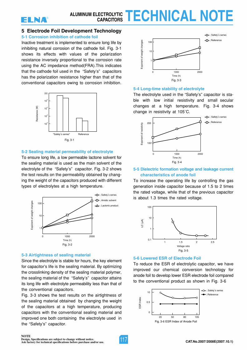
NOTEDesign, Specifications are subject to change without notice.Ask factory for technical specifications before purchase and/or use. CAT.No.2007/2008E(2007.10.1)
ALUMINUM ELECTROLYTICCAPACITORS TECHNICAL NOTE
102
"Safety,s series" Reference
Res
ista
nce
(W)
103
104
105
( )
Fig. 3-1
Fig. 3-3
100
10
1
0 1000
Time (h)
Exp
onen
t of w
eigh
t cha
nges
2000
; Reference
; Safety,s series
Fig. 3-2
100
10
1
0 1000
Time (h)
Exp
onen
t of w
eigh
t cha
nges
2000
; Safety,s series
; Amidic solvent
Fig. 3-4
200
100
0 1000
Time (h)
Fig. 3-5
Fig. 3-6 ESR Index of Anode Foil
Voltage ratio
Exp
onen
t of r
esis
tivity
2000
; Reference
; Safety,s series
; Safety,s series
; Reference
; Lactonic product
10
100
1
0.1
LC (
A)
ES
R In
dex
1.51 2 2.5
10
0.5
0
20 50 80 105
5 Electrode Foil Development Technology5-1 Corrosion inhibition of cathode foilInactive treatment is implemented to ensure long life byinhibiting natural corrosion of the cathode foil. Fig. 3-1shows its effects with values of the polarizationresistance inversely proportional to the corrosion rateusing the AC impedance method(FRA).This indicatesthat the cathode foil used in the “Safety’s” capacitorshas the polarization resistance higher than that of theconventional capacitors owing to corrosion inhibition.
5-2 Sealing material permeability of electrolyteTo ensure long life, a low permeable lactone solvent forthe sealing material is used as the main solvent of theelectrolyte of the “Safety’s” capacitor. Fig. 3-2 showsthe test results on the permeability obtained by chang-ing the weight of the capacitors produced with differenttypes of electrolytes at a high temperature.
5-3 Airtightness of sealing materialSince the electrolyte is stable for hours, the key elementfor capacitor’s life is the sealing material. By optimizingthe crosslinking density of the sealing material polymer,the sealing material of the “Safety’s” capacitor attainsits long life with electrolyte permeability less than that ofthe conventional capacitors.Fig. 3-3 shows the test results on the airtightness ofthe sealing material obtained by changing the weightof the capacitors at a high temperature, producingcapacitors with the conventional sealing material andimproved one both containing the electrolyte used inthe “Safety’s” capacitor.
5-4 Long-time stability of electrolyteThe electrolyte used in the “Safety’s” capacitor is sta-ble with low initial resistivity and small secularchanges at a high temperature. Fig. 3-4 showschange in resistivity at 105˚C.
5-5 Dielectric formation voltage and leakage currentcharacteristics of anode foil
To increase the operating life by controlling the gasgeneration inside capacitor because of 1.5 to 2 timesthe rated voltage, while that of the previous capacitoris about 1.3 times the rated voltage.
5-6 Lowered ESR of Electrode FoilTo reduce the ESR of electrolytic capacitor, we haveimproved our chemical conversion technology foranode foil to develop lower ESR electrode foil comparedto the conventional product as shown in Fig. 3-6
®
117
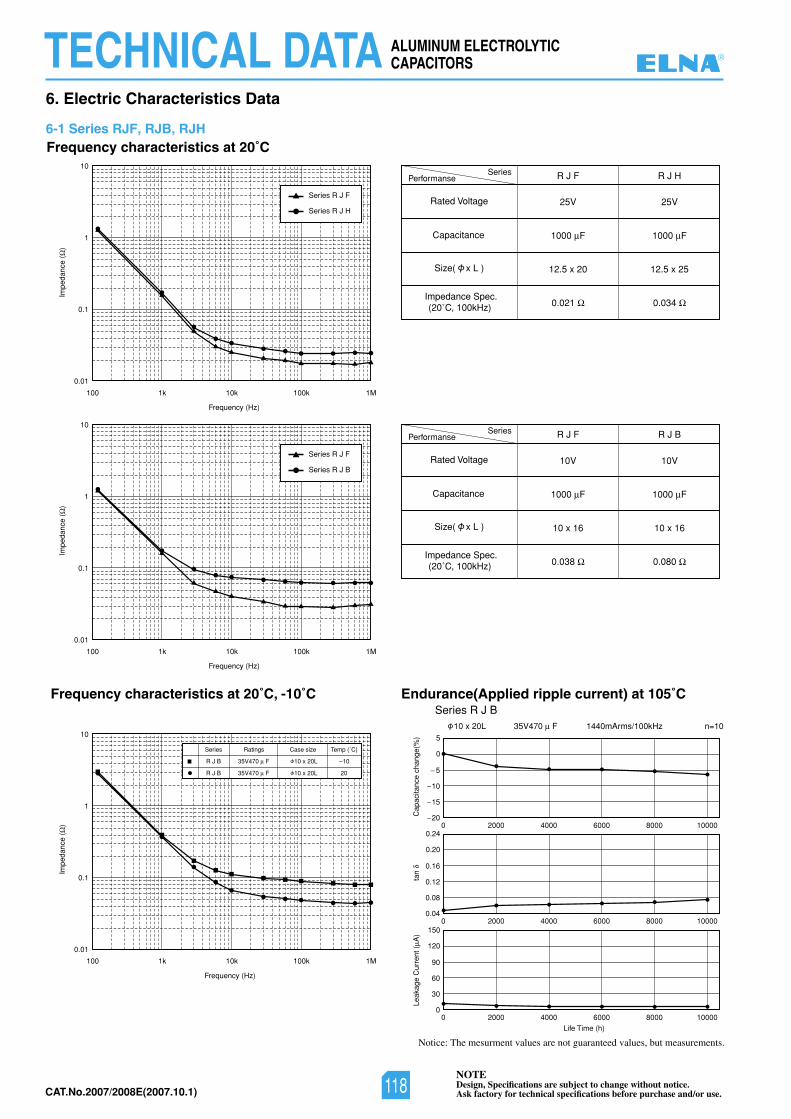
NOTEDesign, Specifications are subject to change without notice.Ask factory for technical specifications before purchase and/or use.CAT.No.2007/2008E(2007.10.1)
Impe
danc
e (
)Im
peda
nce
()
Performanse
Rated Voltage
Capacitance
R J F
25V
1000 F
12.5 x 20
0.021
R J H
25V
1000 F
12.5 x 25
0.034Impedance Spec.(20˚C, 100kHz)
Size( x L )
Series
100
0.01
0.1
1
10
1k 10k
Frequency (Hz)
100k 1M
Frequency characteristics at 20˚C, -10˚C
Series R J H
Series R J F
Series R J B
Series R J F
100
0.01
0.1
1
10
1k 10k
Frequency (Hz)
Frequency (Hz)
100k 1M
Impe
danc
e (
)
100
0.01
0.1
1
10
1k 10k 100k 1M
Performanse
Rated Voltage
Capacitance
R J F R J B
Impedance Spec.(20˚C, 100kHz)
Size( x L )
Series
10V
1000 F
10 x 16
0.038
10V
1000 F
10 x 16
0.080
Series
R J B
Ratings
35V470 F
Case size Temp (˚C)
10 x 20L 10
R J B 35V470 F 10 x 20L 20
Life Time (h)
Endurance(Applied ripple current) at 105˚C
n=101440mArms/100kHz35V470 F
Series R J B10 x 20L
Cap
acita
nce
chan
ge(%
)ta
nLe
akag
e C
urre
nt (
A)
0 2000 4000 6000 8000 10000
10
5
15
20
0
5
0 2000 4000 6000 8000 10000
0.12
0.16
0.08
0.04
0.20
0.24
0 2000 4000 6000 8000 10000
60
90
30
0
120
150
Frequency characteristics at 20˚C
Notice: The mesurment values are not guaranteed values, but measurements.
6. Electric Characteristics Data
6-1 Series RJF, RJB, RJH
ALUMINUM ELECTROLYTICCAPACITORSTECHNICAL DATA ®
118
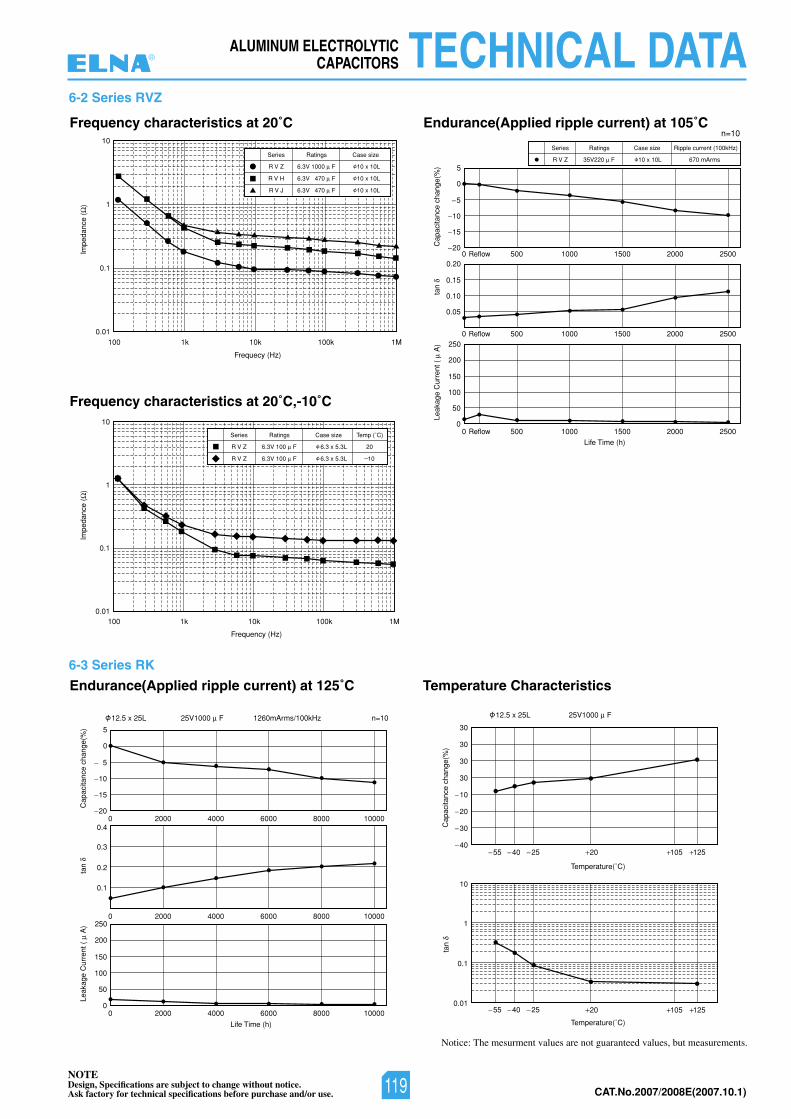
NOTEDesign, Specifications are subject to change without notice.Ask factory for technical specifications before purchase and/or use. CAT.No.2007/2008E(2007.10.1)
ALUMINUM ELECTROLYTICCAPACITORS TECHNICAL DATA
Impe
danc
e (
)
1000.01
0.1
1
10
1k 10k
Frequecy (Hz)
100k 1M
Life Time (h)
Frequency characteristics at 20˚C Endurance(Applied ripple current) at 105˚C
Endurance(Applied ripple current) at 125˚C Temperature Characteristics
Frequency characteristics at 20˚C,-10˚C
Impe
danc
e (
)
1000.01
0.1
1
10
1k 10k
Frequency (Hz)
100k 1M
n=101260mArms/100kHz25V1000 F 25V1000 F12.5 x 25L 12.5 x 25L
Series
R V Z
Ratings
35V220 F
Case size Ripple current (100kHz)
10 x 10L 670 mArms
Cap
acita
nce
chan
ge(%
)
Cap
acita
nce
chan
ge(%
)
tan
tan
Leak
age
Cur
rent
(
A)
0 2000 4000 6000 8000 10000
10
5
15
20
0
5
0 2000 4000 6000 8000 10000
0.3
0.2
0.1
0.4
0 2000 4000 6000 8000 10000
100
150
50
0
200
250
Series
R V Z
Ratings
6.3V 1000 F
Case size
10 x 10L
R V H 6.3V 470 F 10 x 10L
R V J 6.3V 470 F 10 x 10L
Series
R V Z
Ratings
6.3V 100 F
Case size Temp (˚C)
6.3 x 5.3L
6.3 x 5.3L
20
R V Z 6.3V 100 01F
Life Time (h)
n=10
Cap
acita
nce
chan
ge(%
)ta
nLe
akag
e C
urre
nt (
A
)
0 500Reflow 1000 1500 2000 2500
10
5
15
20
0
5
0 500 1000 1500 2000 2500
0.10
0.15
0.05
0.20
0 500
Reflow
Reflow 1000 1500 2000 2500
100
150
50
30
30
30
30
10
1
0.1
0.01
10
20
30
40 55 40 25
55 40 25
20 105 125
20 105 125
0
200
250
Temperature(˚C)
Temperature(˚C)
6-2 Series RVZ
6-3 Series RK
Notice: The mesurment values are not guaranteed values, but measurements.
®
119
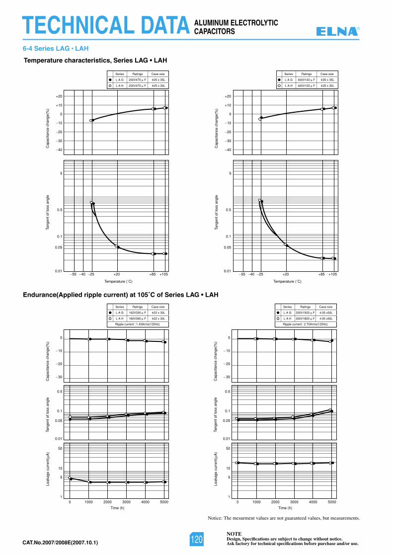
NOTEDesign, Specifications are subject to change without notice.Ask factory for technical specifications before purchase and/or use.CAT.No.2007/2008E(2007.10.1)
ALUMINUM ELECTROLYTICCAPACITORSTECHNICAL DATA
6-4 Series LAG • LAH
Notice: The mesurment values are not guaranteed values, but measurements.
Cap
acita
nce
chan
ge(%
)Le
akag
e cu
rren
t(A
)
Endurance(Applied ripple current) at 105˚C of Series LAG • LAH
Tang
ent o
f los
s an
gle
Temperature (˚C)
Cap
acita
nce
chan
ge(%
)Ta
ngen
t of l
oss
angl
e
Time (h)
0
+10
+20
+20
0 1000 2000 3000 4000 5000
+85 +1050.01
0
0.5
0.1
0.05
0.01
1
5
10
50
0.05
0.1
0.5
5
Series
L A G
Ratings
200V470 F
Case size
25 x 35L
L A H 200V470 F 25 x 30L
Series
L A G
Ratings
162V330 F
Case size
22 x 30L
L A H 160V390 F
Ripple current : 1.43Arms(120Hz)
22 x 30L
Cap
acita
nce
chan
ge(%
)Ta
ngen
t of l
oss
angl
e
Temperature (˚C)
0
+10
+20
4055 25 4055 25 +20 +85 +1050.01
0.05
0.1
0.5
5
Series
L A G
Ratings
400V120 F
Case size
25 x 35L
L A H 400V120 F 25 x 30L
Leak
age
curr
ent(
A)
Cap
acita
nce
chan
ge(%
)Ta
ngen
t of l
oss
angl
e
Time (h)
0 1000 2000 3000 4000 5000
0
0.5
0.1
0.05
0.01
1
5
10
50
Series
L A G
Ratings
200V1500 F
Case size
35 x50L
L A H 200V1800 F
Ripple current : 2.70Arms(120Hz)
35 x50L
10
20
30
10
20
30
10
20
30
40
10
20
30
40
Temperature characteristics, Series LAG • LAH
®
120
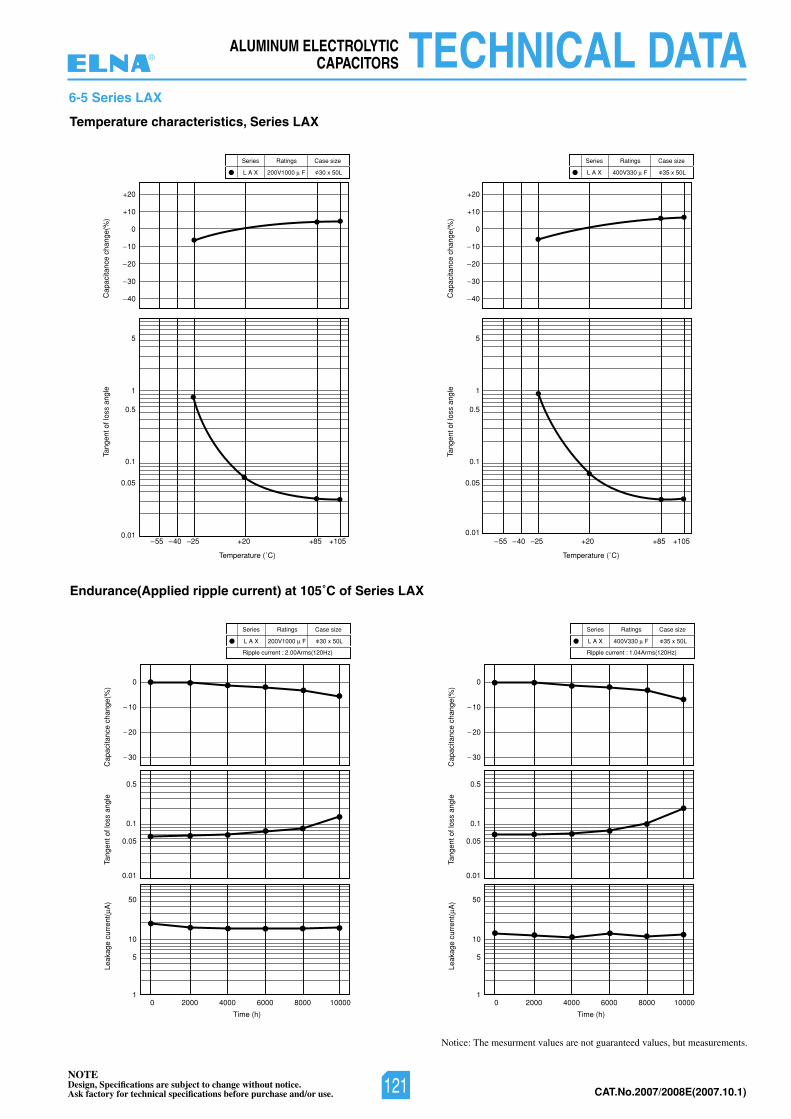
NOTEDesign, Specifications are subject to change without notice.Ask factory for technical specifications before purchase and/or use. CAT.No.2007/2008E(2007.10.1)
ALUMINUM ELECTROLYTICCAPACITORS TECHNICAL DATA
6-5 Series LAX
Notice: The mesurment values are not guaranteed values, but measurements.
Cap
acita
nce
chan
ge(%
)Le
akag
e cu
rren
t(A
)
Endurance(Applied ripple current) at 105˚C of Series LAX
Tang
ent o
f los
s an
gle
Temperature (˚C)
Cap
acita
nce
chan
ge(%
)Ta
ngen
t of l
oss
angl
e
Time (h)
0
+10
+20
4055 25 4055 25+20
0 2000 4000 6000 8000 10000
+85 +1050.01
0
0.5
0.1
0.05
0.01
1
5
10
50
0.05
0.1
0.5
1
5
Series
L A X
Ratings
200V1000 F
Case size
30 x 50L
Series
L A X
Ratings
200V1000 F
Case size
30 x 50L
Ripple current : 2.00Arms(120Hz)
Cap
acita
nce
chan
ge(%
)Ta
ngen
t of l
oss
angl
e
Temperature (˚C)
10
0
+10
+20
20
30
40
10
20
30
40
+20 +85 +1050.01
0.05
0.1
0.5
1
5
Series
L A X
Ratings
400V330 F
Case size
35 x 50L
Leak
age
curr
ent(
A)
Cap
acita
nce
chan
ge(%
)Ta
ngen
t of l
oss
angl
e
Time (h)
0 2000 4000 6000 8000 10000
0
10
20
30
10
20
30
0.5
0.1
0.05
0.01
1
5
10
50
Series
L A X
Ratings
400V330 F
Case size
35 x 50L
Ripple current : 1.04Arms(120Hz)
Temperature characteristics, Series LAX
®
121
NOTEDesign, Specifications are subject to change without notice.Ask factory for technical specifications before purchase and/or use.CAT.No.2007/2008E(2007.10.1)
MEMO®
122
NOTEDesign, Specifications are subject to change without notice.Ask factory for technical specifications before purchase and/or use. CAT.No.2007/2008E(2007.10.1)
Tantalum Chip Capacitors
List of Contents
1. Type List, Systematized Classification • • • • • • • • • • • • • • • • • • • 1242. Cautions for Using • • • • • • • • • • • • • • • • • • • • • • • • • • • • • • • • • • • 1253. Taping • • • • • • • • • • • • • • • • • • • • • • • • • • • • • • • • • • • • • • • • • • • • 1274. Dimensions, Marking, Part No System • • • • • • • • • • • • • • • • • • 1285. SYF Series Standard Ratings • • • • • • • • • • • • • • • • • • • • • • • 1296. SKY Series Standard Ratings • • • • • • • • • • • • • • • • • • • • • • • 1327. SYL Series Standard Ratings • • • • • • • • • • • • • • • • • • • • • • • • 1378. Technical Notes • • • • • • • • • • • • • • • • • • • • • • • • • • • • • • • • • • • • • 138
CAT.No.2007/2008E(2007.10.1)123
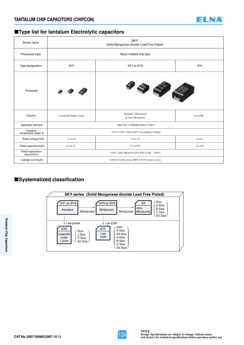
NOTEDesign, Specifications are subject to change without notice.Ask factory for technical specifications before purchase and/or use.CAT.No.2007/2008E(2007.10.1)
TANTALUM CHIP CAPACITORS (CHIPCON)
Type list for tantalum Electrolytic capacitors
Systematized classification
Processed style
Series name
Type designation
Resin molded chip type
SKY(Solid Manganese dioxide Lead-Free Plated)
SYF SY1 to SY9 SYL
Photograph
serutaeF Lowprofile Hight:1.2mmStandard , Miniaturied
& Ultra MiniaturiedLow ESR
Rated voltage(V DC)
Rated capacitance(µF)
Rated capacitancetolerance(%)
Leakage current(µA)
Applicable standard
Categorytemperature range(˚C)
JISC5101-3:1998(IEC60384-3:1989)
55 to 125˚C (Above 85˚C use category voltage)
2.5 to 25 2.5 to 35
0.1 to 47 0.1 to 470
4 to16
1 to 330
0.01CV(5 min) or less (SK9: 0.1CV(5 min) or less)
10%, 20% (However SY9, SYF-J only 20%)
Low-profile Loe ESR
SKY series (Solid Manganese dioxide Lead Free Plated)
SizeA SizeB SizeC SizeD0 Size
SizeJ SizeP SizeA2 Size
SY1 to SY4
Standard
SYF
Lowprofileunder1.2mm
Miniaturied Miniaturied
SizeP SizeA2 SizeA SizeB SizeC SizeD0 Size
SY5 to SY8
Miniaturied
SYLLowESR
SY
UltraMiniaturied
®
124
Tantalum C
hip Capacitors
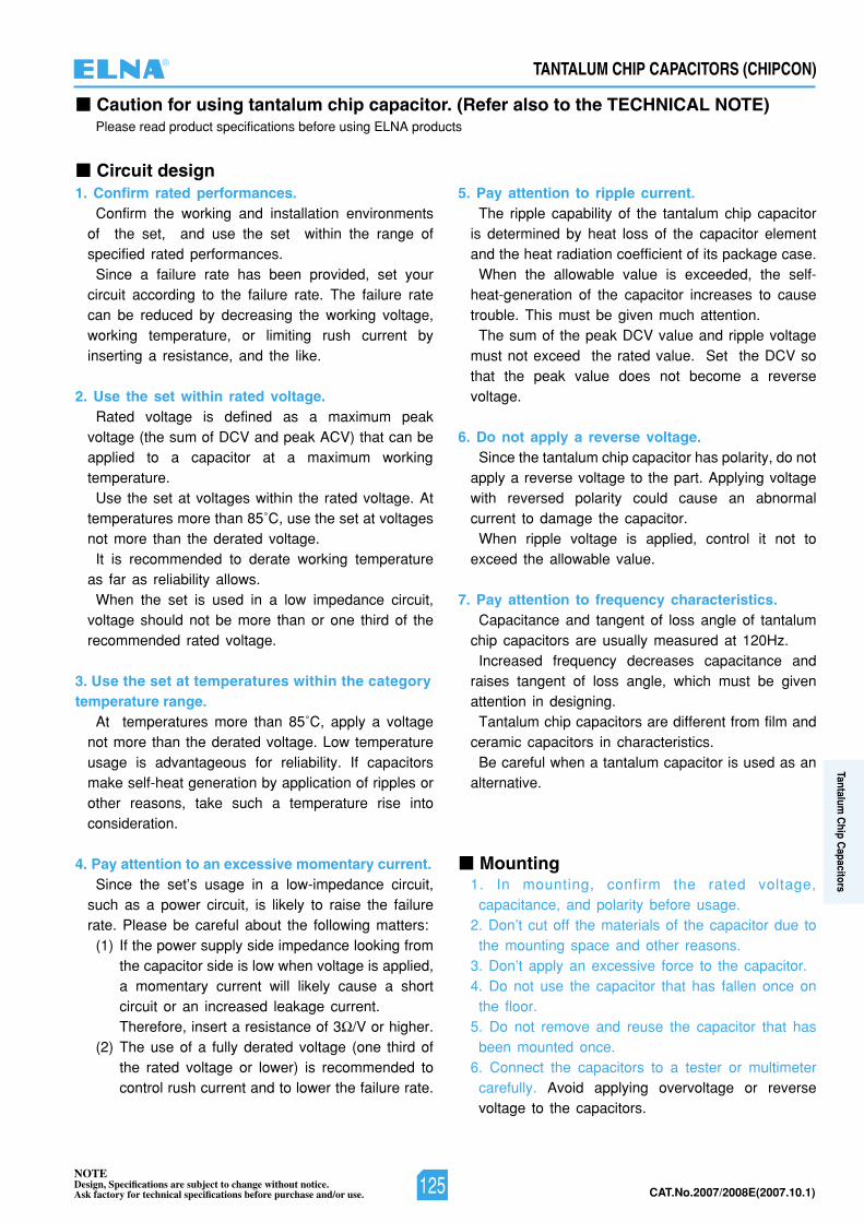
NOTEDesign, Specifications are subject to change without notice.Ask factory for technical specifications before purchase and/or use. CAT.No.2007/2008E(2007.10.1)
TANTALUM CHIP CAPACITORS (CHIPCON)
Caution for using tantalum chip capacitor. (Refer also to the TECHNICAL NOTE)Please read product specifications before using ELNA products
Circuit design1. Confirm rated performances.
Confirm the working and installation environmentsof the set, and use the set within the range ofspecified rated performances.
Since a failure rate has been provided, set yourcircuit according to the failure rate. The failure ratecan be reduced by decreasing the working voltage,working temperature, or limiting rush current byinserting a resistance, and the like.
2. Use the set within rated voltage.Rated voltage is defined as a maximum peak
voltage (the sum of DCV and peak ACV) that can beapplied to a capacitor at a maximum workingtemperature.
Use the set at voltages within the rated voltage. Attemperatures more than 85˚C, use the set at voltagesnot more than the derated voltage.
It is recommended to derate working temperatureas far as reliability allows.
When the set is used in a low impedance circuit,voltage should not be more than or one third of therecommended rated voltage.
3. Use the set at temperatures within the categorytemperature range.
At temperatures more than 85˚C, apply a voltagenot more than the derated voltage. Low temperatureusage is advantageous for reliability. If capacitorsmake self-heat generation by application of ripples orother reasons, take such a temperature rise intoconsideration.
4. Pay attention to an excessive momentary current.Since the set’s usage in a low-impedance circuit,
such as a power circuit, is likely to raise the failurerate. Please be careful about the following matters:
(1) If the power supply side impedance looking fromthe capacitor side is low when voltage is applied,a momentary current will likely cause a shortcircuit or an increased leakage current.Therefore, insert a resistance of 3 /V or higher.
(2) The use of a fully derated voltage (one third ofthe rated voltage or lower) is recommended tocontrol rush current and to lower the failure rate.
5. Pay attention to ripple current.The ripple capability of the tantalum chip capacitor
is determined by heat loss of the capacitor elementand the heat radiation coefficient of its package case.
When the allowable value is exceeded, the self-heat-generation of the capacitor increases to causetrouble. This must be given much attention.
The sum of the peak DCV value and ripple voltagemust not exceed the rated value. Set the DCV sothat the peak value does not become a reversevoltage.
6. Do not apply a reverse voltage.Since the tantalum chip capacitor has polarity, do not
apply a reverse voltage to the part. Applying voltagewith reversed polarity could cause an abnormalcurrent to damage the capacitor.
When ripple voltage is applied, control it not toexceed the allowable value.
7. Pay attention to frequency characteristics.Capacitance and tangent of loss angle of tantalum
chip capacitors are usually measured at 120Hz.Increased frequency decreases capacitance and
raises tangent of loss angle, which must be givenattention in designing.
Tantalum chip capacitors are different from film andceramic capacitors in characteristics.
Be careful when a tantalum capacitor is used as analternative.
1. In mounting, confirm the rated voltage,capacitance, and polarity before usage.
2. Don’t cut off the materials of the capacitor due tothe mounting space and other reasons.
3. Don’t apply an excessive force to the capacitor.4. Do not use the capacitor that has fallen once on
the floor.5. Do not remove and reuse the capacitor that has
been mounted once.6. Connect the capacitors to a tester or multimeter
carefully. Avoid applying overvoltage or reversevoltage to the capacitors.
Mounting
®
125
Tantalum C
hip Capacitors
NOTEDesign, Specifications are subject to change without notice.Ask factory for technical specifications before purchase and/or use.CAT.No.2007/2008E(2007.10.1)
TANTALUM CHIP CAPACITORS (CHIPCON)
Caution for using tantalum chip capacitor. (Refer also to the TECHNICAL NOTE)Please read product specifications before using ELNA products
Soldering
Transportation
1. Be sure to observe the soldering conditions stipu-lated in our catalogs and specifications.It is very important in terms of reliability that solderingis completed in the shortest possible time and underconditions where the joints will be soldered perfectly.
2. Wash products immediately after the solderingprocess so that the dregs of flux and the remainingacid and alkali will not be left.
3. Avoid the use of ultrasonic cleaning wheneverpossible.If the use of ultrasonic cleaning is unavoidable, makea trial of the system in conditions severer than thosein actual cleaning to check for any abnormality.
4. Melting point of terminal plating(Sn 100%) is 232˚C.If the soldering of lead free at 232˚C or less, confirmthe presence of abnormality enough.(For the reflow method, soldering from the peaktemperature 235˚C to 250˚C is recommended.)
1. Do not touch a capacitor directly when the set isbeing used, it could cause an electric shock.Never place conductive solutions, such as acid andalkali, on the capacitor. Those solutions could cause ashort circuit between circuits or in the capacitor.
2. If a strange smell or smoke is generated from aset in use, turn off the main power supply for the setimmediately.
3. If a capacitor burns, combustion and decompositiongases are generated from the wold resin and the like.Therefore, do not get close to the capacitor.
1. Keep the products clean at room temperatures(not more than 40˚C) and relative humidities (not morethan 70˚C).Leaving them at high temperatures and humiditiesreduces their solderability significantly. Storage inpackaged condition is recommended.
2. Keep the product out of direct sun exposure.
3. Store products in a manner that does not applyunnecessary external force.
4. Avoid storage in an area where vibration exists.
5. Fumigation treatment with toxic gas covering thewhole wooden container frames as moth proofingduring shipment may leave residual toxic gas.
6. Storage for a long period of time deterioratespackaging materials.Pay attention to taping materials in particular, sincethey deteriorate easily.It is recommended to use the capacitor within one year.
Do not drop the products on the floor or on a table.Since these products use solidified tantalum powder,handle the capacitors carefully because excessivevibration or shock will likely cause reliability reduction.
If any capacitors need to be disposed, treat asindustrial waste.
1. In addition to the above-mentioned matters, besure to confirm the contents of the following document;Technical report of Japan Electronics and InformationTechnology Industries Association, EIAJ RCR-2368B,the “Guideline of notabilia for fixed tantalum electrolyticcapacitors with solid electrolyte for use in electronicequipment”
2. Please understand beforehand that the contents ofour catalogs are subject to alteration for improvementwithout prior notice.Data mentioned in our catalog are representativevalues that do not assure performances.
In a emergency
Storage
Other notes
Disposal
®
126
Tantalum C
hip Capacitors
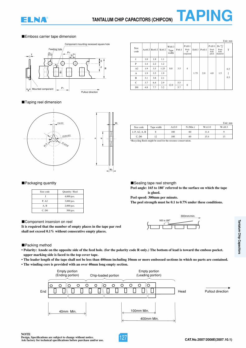
NOTEDesign, Specifications are subject to change without notice.Ask factory for technical specifications before purchase and/or use. CAT.No.2007/2008E(2007.10.1)
TANTALUM CHIP CAPACITORS (CHIPCON) TAPINGEmboss carrier tape dimension
Taping reel dimension
Packaging quantity Sealing tape reel strength
Packing method
Unit: mm
Unit: mm
*Recycling Reels might be used for the resource conservation.
J
A2
A
B
C
D0
J, P, A2, A, B
C, D0
8 180 60 11.4 9
12 180 60 15.4 13
Sizecode
Size code Tape width A 2.0 N (Min.) W2 1.0 W1 0.3
1.0 1.8 1.1
1.9 3.5 1.25
P 1.4 2.2 1.2
1.9 3.5 1.9
3.1 3.8 2.1
3.7 6.4 2.9
4.8 7.7 3.2
8.0 3.5 4
12.05.5
85.7
1.75 2.0 4.0 1.5
0.2
0.3
~
A0 0.2 B0 0.2 K 0.2W 0.3
Tapewidth
F 0.1
P1 0.1Pitch
ofcomponent
E 0.1 P2 0.1
P1 0.1Feedholepitch
D0
Feedhole
diameter
0.10
T
40mm Min.
End Pullout direction
400mm Min.
100mm Min.
Head
Empty portion(Leading portion)Chip-loaded portion
Empty portion(Ending portion)
• Polarity: Anode on the opposite side of the feed hole. (for the polarity code R only.) The bottom of lead is toward the emboss pocket.upper marking side is faced to the top cover tape.
• The leader length of the tape shall not be less than 400mm including 10mm or more embossed sections in which no parts are contained.• The winding core is provided with an over 40mm long empty section.
Component insersion on reelIt is required that the number of empty places in the tape par reelshall not exceed 0.1% without consecutive empty places.
Peel angle: 165 to 180˚ referred to the surface on which the tapeis glued.
Peel speed: 300mm per minute.The peel strength must be 0.1 to 0.7N under these conditions.P, A2
A, B
C, D0
3,000 pcs.
J 4,000 pcs.
2,000 pcs.
500 pcs.
Size code Quantity / Reel
Feeding hole
Mounted component
Component mounting recessed square hole
Pullout direction
300mm/min.
®
127
Tantalum C
hip Capacitors
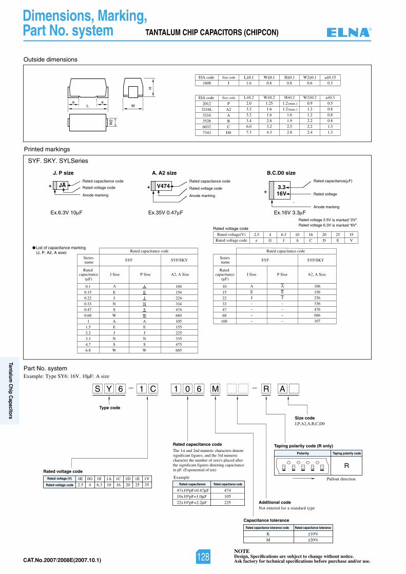
NOTEDesign, Specifications are subject to change without notice.Ask factory for technical specifications before purchase and/or use.CAT.No.2007/2008E(2007.10.1)
TANTALUM CHIP CAPACITORS (CHIPCON)
Dimensions, Marking,Part No. system
WLa
H
a
W2
Rated capacitance( F)
Rated voltage 2.5V is marked “2V”.Rated voltage 6.3V is marked “6V”.
Ex.16V 3.3 FEx.6.3V 10 F Ex.35V 0.47 F
B.C.D0 sizeJ. P size A. A2 size
Rated voltage
Rated capacitance code
Rated voltage code
Anode marking
Anode marking
Rated capacitance code
Rated voltage code
Anode marking
Outside dimensions
EIA code a 0.3W2 0.2H 0.2W 0.2L 0.2Size code
Printed markings
SYF. SKY. SYLSeries
2012
3216L
3216
3528
6032
7343
2.0 1.25 1.2(max.) 0.9 0.5
3.2 1.6 1.2(max.) 1.2 0.8
3.2 1.6 1.6 1.2 0.8
3.4 2.8 1.9 2.2 0.8
6.0 3.2 2.5 2.2 1.3
7.3 4.3 2.8 2.4 1.3
P
A2
A
B
C
D0
EIA code a 0.15W2 0.1H 0.1W 0.1L 0.1Size code
1608 J 1.6 0.8 0.8 0.6 0.3
Rated voltage code
Rated voltage(V)
Rated voltage code2.5 4 6.3 10 16 20 25 35
e G J A C D E V
List of capacitance marking (J, P, A2, A size)
Part No. systemExample: Type SY6: 16V. 10µF: A size
J,P,A2,A,B,C,D0
Pullout direction
Polarity Taping polarity code
Size code
Type code
Not entered for a standard typeAdditional code
Taping polarity code (R only)
Rated capacitance tolerance code Rated capacitance tolerance
Capacitance tolerance
S Y 6 1 0 6 M R A1 C
R
Example
Rated capacitance code
K
M
10%
20%
Rated voltage code
Rated voltage (V)
Rated voltage code
0E
2.5
0G
4
0J
6.3
1A
10
1C
16
1D
20
1E
25
1V
35 Rated capacitance Rated capacitance code
47x104pF=0.47 F
10x105pF=1.0 F
22x105pF=2.2 F
474
105
225
The 1st and 2nd numeric characters denote significant figures, and the 3rd numeric character the number of zero's placed after the significant figures denoting capacitance in pF. (Exponential of ten)
JA+ 3.3 16V+
V474+
105
155
224
334
474
684
S
W
225
475
685
335
A
E
J
N
J
N
S
W
A
E
104
154
J
W6.8
4.7
N
S
3.3
J
1.5
1
0.1
Rated capacitance code
SYF
J SizeRated
capacitance( F)
Series name
P Size A2, A Size
SYF/SKY
2.2
E
A
0.68
0.47
E
A
0.15
W
N
S
0.33
0.22
100
68
47
33
22
15
10
Rated capacitance code
SYF
J SizeRated
capacitance( F)
Series name
P Size A2, A Size
SYF/SKY
106
156
226
336
476
686
107
A
E
J
–
–
–
–
A
E
J
–
–
–
–
_ _
®
128
Tantalum C
hip Capacitors
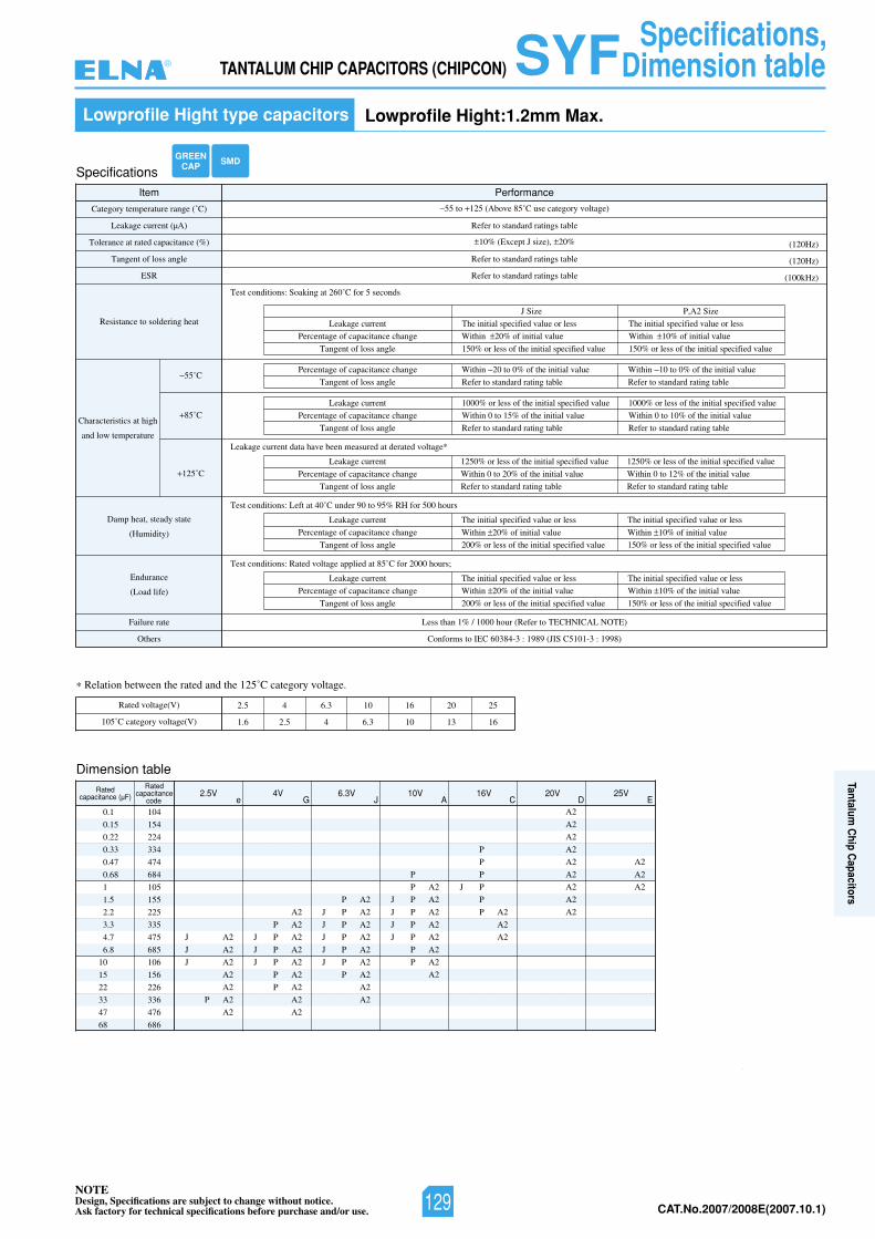
NOTEDesign, Specifications are subject to change without notice.Ask factory for technical specifications before purchase and/or use. CAT.No.2007/2008E(2007.10.1)
e G J A C D E
Specifications
Item Performance
Category temperature range (˚C)
Tolerance at rated capacitance (%)
Leakage current (µA)
Tangent of loss angle
ESR
Resistance to soldering heat
Characteristics at high
and low temperature
55˚C
85˚C
125˚C
Damp heat, steady state
(Humidity)
Endurance
(Load life)
Failure rate
)8991:3-1015CSIJ(9891:3-48306CEIotsmrofnoCsrehtO
Less than 1% / 1000 hour (Refer to TECHNICAL NOTE)
55 to 125 (Above 85˚C use category voltage)
Test conditions: Soaking at 260˚C for 5 seconds
Leakage current data have been measured at derated voltage*
Test conditions: Left at 40˚C under 90 to 95% RH for 500 hours
10% (Except J size), 20%
Refer to standard ratings table
(120Hz)
(120Hz)
(100kHz)
Leakage current
Percentage of capacitance change
Tangent of loss angle
Percentage of capacitance change
Tangent of loss angle
Leakage current
Percentage of capacitance change
Tangent of loss angle
Refer to standard ratings table
Refer to standard ratings table
The initial specified value or less
Within 20% of initial value
150% or less of the initial specified value
Within 20 to 0% of the initial value
Refer to standard rating table
Within 10 to 0% of the initial value
Refer to standard rating table
1000% or less of the initial specified value
Within 0 to 15% of the initial value
Refer to standard rating table
1000% or less of the initial specified value
Within 0 to 10% of the initial value
Refer to standard rating table
Leakage current
Percentage of capacitance change
Tangent of loss angle
1250% or less of the initial specified value
Within 0 to 20% of the initial value
Refer to standard rating table
1250% or less of the initial specified value
Within 0 to 12% of the initial value
Refer to standard rating table
Test conditions: Rated voltage applied at 85˚C for 2000 hours;
Leakage current
Percentage of capacitance change
Tangent of loss angle
The initial specified value or less
Within 20% of the initial value
200% or less of the initial specified value
The initial specified value or less
Within 10% of the initial value
150% or less of the initial specified value
J Size
The initial specified value or less
Within 10% of initial value
150% or less of the initial specified value
P,A2 Size
Leakage current
Percentage of capacitance change
Tangent of loss angle
The initial specified value or less
200% or less of the initial specified value
Relation between the rated and the 125˚C category voltage.
Rated voltage(V)
105˚C category voltage(V)
2.5 4 6.3 10 16 20 25
1.6 2.5 4 6.3 10 13 16
Dimension table
0.1
0.15
0.22
0.33
0.47
0.68
1
1.5
2.2
3.3
4.7
6.8
10
15
22
33
47
68
104
154
224
334
474
684
105
155
225
335
475
685
106
156
226
336
476
686
J A2
J A2
J A2
A2
A2
P A2
A2
A2
P A2
J P A2
J P A2
J P A2
P A2
P A2
A2
A2
P A2
J P A2
J P A2
J P A2
J P A2
J P A2
P A2
A2
A2
P
P A2
J P A2
J P A2
J P A2
J P A2
P A2
P A2
A2
P
P
P
J P
P
P A2
A2
A2
A2
A2
A2
A2
A2
A2
A2
A2
A2
A2
A2
A2
Ratedcapacitance (µF)
Ratedcapacitance
code2.5V 4V 6.3V 10V 16V 20V 25V
GREENCAP SMD
Within 20% of initial value
The initial specified value or less
150% or less of the initial specified value
Within 10% of initial value
TANTALUM CHIP CAPACITORS (CHIPCON) SYFLowprofile Hight type capacitors Lowprofile Hight:1.2mm Max.
Specifications,Dimension table®
129
Tantalum C
hip Capacitors
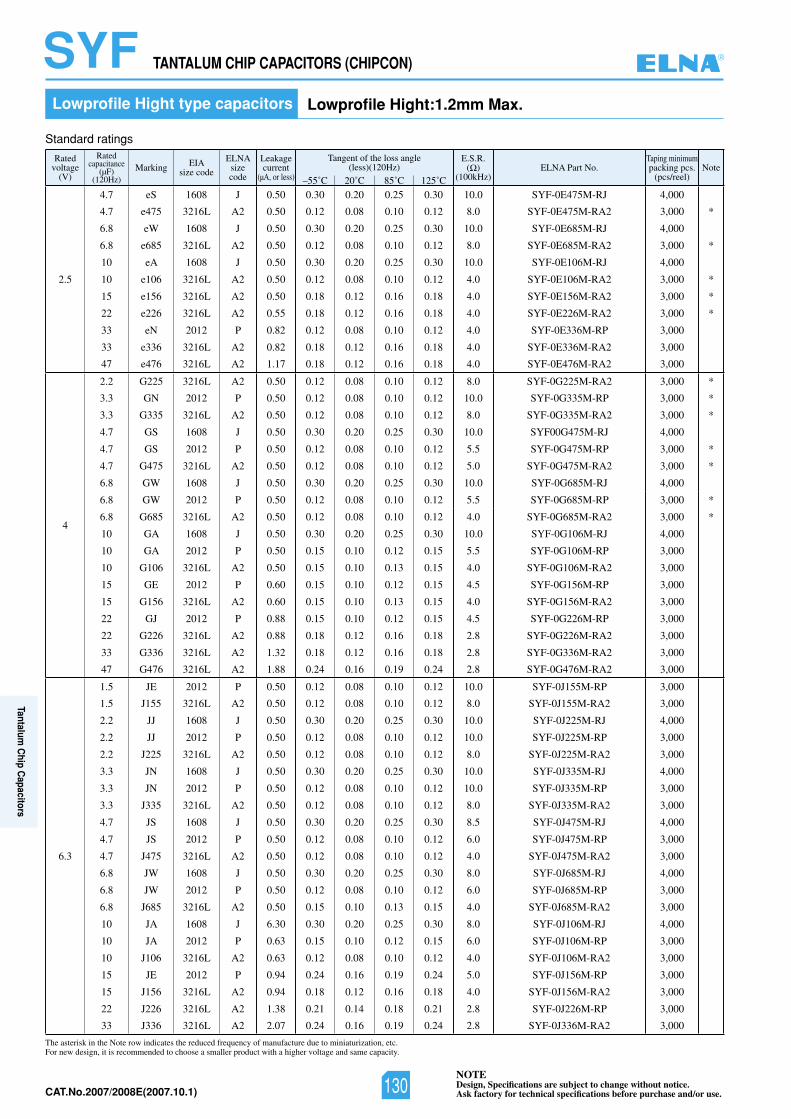
NOTEDesign, Specifications are subject to change without notice.Ask factory for technical specifications before purchase and/or use.CAT.No.2007/2008E(2007.10.1)
Ratedvoltage
(V)
Ratedcapacitance
(µF)(120Hz)
Marking EIAsize code
ELNAsizecode
Leakagecurrent
(µA, or less)
Tangent of the loss angle(less)(120Hz)
E.S.R.( )
(100kHz)ELNA Part No.
Taping minimumpacking pcs.
(pcs/reel)Note
–55˚C 20˚C 85˚C 125˚C
2.5
4.7 eS 1608 J 0.50 0.30 0.20 0.25 0.30 10.0 SYF-0E475M-RJ 4,000
4.7 e475 3216L A2 0.50 0.12 0.08 0.10 0.12 8.0 SYF-0E475M-RA2 3,000 *
6.8 eW 1608 J 0.50 0.30 0.20 0.25 0.30 10.0 SYF-0E685M-RJ 4,000
6.8 e685 3216L A2 0.50 0.12 0.08 0.10 0.12 8.0 SYF-0E685M-RA2 3,000 *
10 eA 1608 J 0.50 0.30 0.20 0.25 0.30 10.0 SYF-0E106M-RJ 4,000
10 e106 3216L A2 0.50 0.12 0.08 0.10 0.12 4.0 SYF-0E106M-RA2 3,000 *
15 e156 3216L A2 0.50 0.18 0.12 0.16 0.18 4.0 SYF-0E156M-RA2 3,000 *
22 e226 3216L A2 0.55 0.18 0.12 0.16 0.18 4.0 SYF-0E226M-RA2 3,000 *
33 eN 2012 P 0.82 0.12 0.08 0.10 0.12 4.0 SYF-0E336M-RP 3,000
33 e336 3216L A2 0.82 0.18 0.12 0.16 0.18 4.0 SYF-0E336M-RA2 3,000
47 e476 3216L A2 1.17 0.18 0.12 0.16 0.18 4.0 SYF-0E476M-RA2 3,000
4
2.2 G225 3216L A2 0.50 0.12 0.08 0.10 0.12 8.0 SYF-0G225M-RA2 3,000 *
3.3 GN 2012 P 0.50 0.12 0.08 0.10 0.12 10.0 SYF-0G335M-RP 3,000 *
3.3 G335 3216L A2 0.50 0.12 0.08 0.10 0.12 8.0 SYF-0G335M-RA2 3,000 *
4.7 GS 1608 J 0.50 0.30 0.20 0.25 0.30 10.0 SYF00G475M-RJ 4,000
4.7 GS 2012 P 0.50 0.12 0.08 0.10 0.12 5.5 SYF-0G475M-RP 3,000 *
4.7 G475 3216L A2 0.50 0.12 0.08 0.10 0.12 5.0 SYF-0G475M-RA2 3,000 *
6.8 GW 1608 J 0.50 0.30 0.20 0.25 0.30 10.0 SYF-0G685M-RJ 4,000
6.8 GW 2012 P 0.50 0.12 0.08 0.10 0.12 5.5 SYF-0G685M-RP 3,000 *
6.8 G685 3216L A2 0.50 0.12 0.08 0.10 0.12 4.0 SYF-0G685M-RA2 3,000 *
10 GA 1608 J 0.50 0.30 0.20 0.25 0.30 10.0 SYF-0G106M-RJ 4,000
10 GA 2012 P 0.50 0.15 0.10 0.12 0.15 5.5 SYF-0G106M-RP 3,000
10 G106 3216L A2 0.50 0.15 0.10 0.13 0.15 4.0 SYF-0G106M-RA2 3,000
15 GE 2012 P 0.60 0.15 0.10 0.12 0.15 4.5 SYF-0G156M-RP 3,000
15 G156 3216L A2 0.60 0.15 0.10 0.13 0.15 4.0 SYF-0G156M-RA2 3,000
22 GJ 2012 P 0.88 0.15 0.10 0.12 0.15 4.5 SYF-0G226M-RP 3,000
22 G226 3216L A2 0.88 0.18 0.12 0.16 0.18 2.8 SYF-0G226M-RA2 3,000
33 G336 3216L A2 1.32 0.18 0.12 0.16 0.18 2.8 SYF-0G336M-RA2 3,000
47 G476 3216L A2 1.88 0.24 0.16 0.19 0.24 2.8 SYF-0G476M-RA2 3,000
6.3
1.5 JE 2012 P 0.50 0.12 0.08 0.10 0.12 10.0 SYF-0J155M-RP 3,000
1.5 J155 3216L A2 0.50 0.12 0.08 0.10 0.12 8.0 SYF-0J155M-RA2 3,000
2.2 JJ 1608 J 0.50 0.30 0.20 0.25 0.30 10.0 SYF-0J225M-RJ 4,000
2.2 JJ 2012 P 0.50 0.12 0.08 0.10 0.12 10.0 SYF-0J225M-RP 3,000
2.2 J225 3216L A2 0.50 0.12 0.08 0.10 0.12 8.0 SYF-0J225M-RA2 3,000
3.3 JN 1608 J 0.50 0.30 0.20 0.25 0.30 10.0 SYF-0J335M-RJ 4,000
3.3 JN 2012 P 0.50 0.12 0.08 0.10 0.12 10.0 SYF-0J335M-RP 3,000
3.3 J335 3216L A2 0.50 0.12 0.08 0.10 0.12 8.0 SYF-0J335M-RA2 3,000
4.7 JS 1608 J 0.50 0.30 0.20 0.25 0.30 8.5 SYF-0J475M-RJ 4,000
4.7 JS 2012 P 0.50 0.12 0.08 0.10 0.12 6.0 SYF-0J475M-RP 3,000
4.7 J475 3216L A2 0.50 0.12 0.08 0.10 0.12 4.0 SYF-0J475M-RA2 3,000
6.8 JW 1608 J 0.50 0.30 0.20 0.25 0.30 8.0 SYF-0J685M-RJ 4,000
6.8 JW 2012 P 0.50 0.12 0.08 0.10 0.12 6.0 SYF-0J685M-RP 3,000
6.8 J685 3216L A2 0.50 0.15 0.10 0.13 0.15 4.0 SYF-0J685M-RA2 3,000
10 JA 1608 J 6.30 0.30 0.20 0.25 0.30 8.0 SYF-0J106M-RJ 4,000
10 JA 2012 P 0.63 0.15 0.10 0.12 0.15 6.0 SYF-0J106M-RP 3,000
10 J106 3216L A2 0.63 0.12 0.08 0.10 0.12 4.0 SYF-0J106M-RA2 3,000
15 JE 2012 P 0.94 0.24 0.16 0.19 0.24 5.0 SYF-0J156M-RP 3,000
15 J156 3216L A2 0.94 0.18 0.12 0.16 0.18 4.0 SYF-0J156M-RA2 3,000
22 J226 3216L A2 1.38 0.21 0.14 0.18 0.21 2.8 SYF-0J226M-RP 3,000
33 J336 3216L A2 2.07 0.24 0.16 0.19 0.24 2.8 SYF-0J336M-RA2 3,000
Lowprofile Hight type capacitors Lowprofile Hight:1.2mm Max.
TANTALUM CHIP CAPACITORS (CHIPCON) SYF
The asterisk in the Note row indicates the reduced frequency of manufacture due to miniaturization, etc.For new design, it is recommended to choose a smaller product with a higher voltage and same capacity.
Standard ratings
®
130
Tantalum C
hip Capacitors
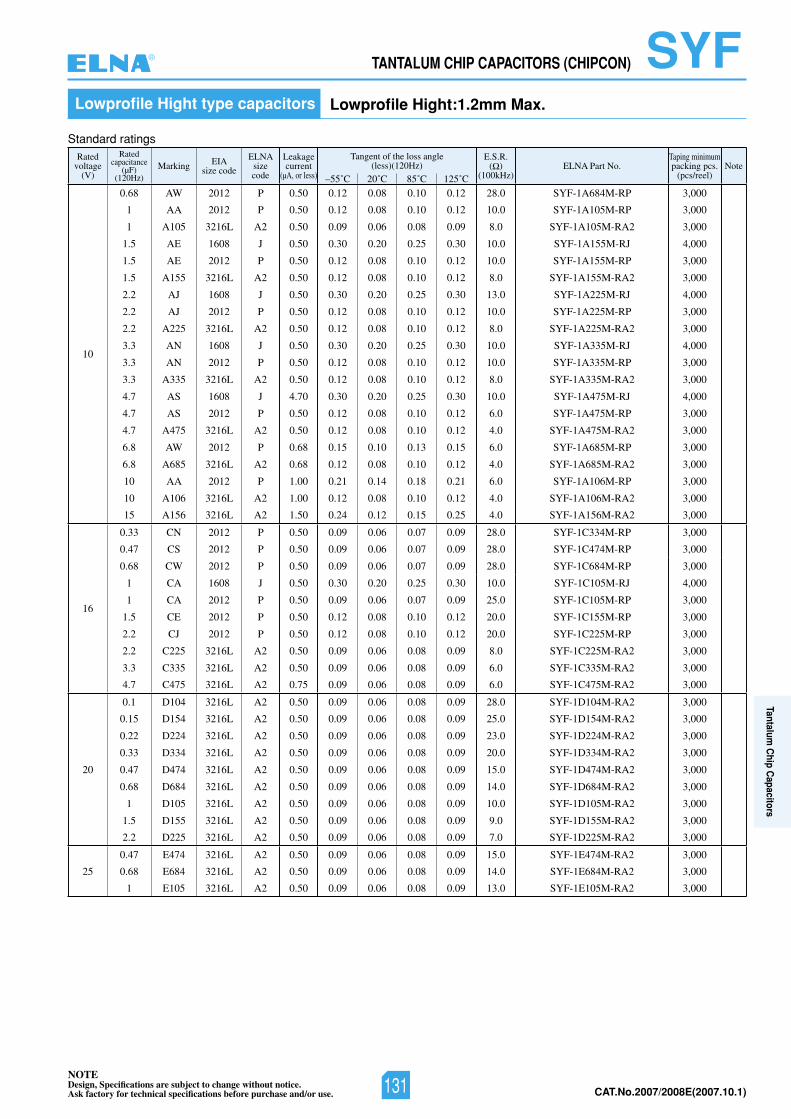
NOTEDesign, Specifications are subject to change without notice.Ask factory for technical specifications before purchase and/or use. CAT.No.2007/2008E(2007.10.1)
Ratedvoltage
(V)
Ratedcapacitance
(µF)(120Hz)
Marking EIAsize code
ELNAsizecode
Leakagecurrent
(µA, or less)
Tangent of the loss angle(less)(120Hz)
E.S.R.( )
(100kHz)ELNA Part No.
Taping minimumpacking pcs.
(pcs/reel)Note
–55˚C 20˚C 85˚C 125˚C
10
0.68 AW 2012 P 0.50 0.12 0.08 0.10 0.12 28.0 SYF-1A684M-RP 3,000
1 AA 2012 P 0.50 0.12 0.08 0.10 0.12 10.0 SYF-1A105M-RP 3,000
1 A105 3216L A2 0.50 0.09 0.06 0.08 0.09 8.0 SYF-1A105M-RA2 3,000
1.5 AE 1608 J 0.50 0.30 0.20 0.25 0.30 10.0 SYF-1A155M-RJ 4,000
1.5 AE 2012 P 0.50 0.12 0.08 0.10 0.12 10.0 SYF-1A155M-RP 3,000
1.5 A155 3216L A2 0.50 0.12 0.08 0.10 0.12 8.0 SYF-1A155M-RA2 3,000
2.2 AJ 1608 J 0.50 0.30 0.20 0.25 0.30 13.0 SYF-1A225M-RJ 4,000
2.2 AJ 2012 P 0.50 0.12 0.08 0.10 0.12 10.0 SYF-1A225M-RP 3,000
2.2 A225 3216L A2 0.50 0.12 0.08 0.10 0.12 8.0 SYF-1A225M-RA2 3,000
3.3 AN 1608 J 0.50 0.30 0.20 0.25 0.30 10.0 SYF-1A335M-RJ 4,000
3.3 AN 2012 P 0.50 0.12 0.08 0.10 0.12 10.0 SYF-1A335M-RP 3,000
3.3 A335 3216L A2 0.50 0.12 0.08 0.10 0.12 8.0 SYF-1A335M-RA2 3,000
4.7 AS 1608 J 4.70 0.30 0.20 0.25 0.30 10.0 SYF-1A475M-RJ 4,000
4.7 AS 2012 P 0.50 0.12 0.08 0.10 0.12 6.0 SYF-1A475M-RP 3,000
4.7 A475 3216L A2 0.50 0.12 0.08 0.10 0.12 4.0 SYF-1A475M-RA2 3,000
6.8 AW 2012 P 0.68 0.15 0.10 0.13 0.15 6.0 SYF-1A685M-RP 3,000
6.8 A685 3216L A2 0.68 0.12 0.08 0.10 0.12 4.0 SYF-1A685M-RA2 3,000
10 AA 2012 P 1.00 0.21 0.14 0.18 0.21 6.0 SYF-1A106M-RP 3,000
10 A106 3216L A2 1.00 0.12 0.08 0.10 0.12 4.0 SYF-1A106M-RA2 3,000
15 A156 3216L A2 1.50 0.24 0.12 0.15 0.25 4.0 SYF-1A156M-RA2 3,000
16
0.33 CN 2012 P 0.50 0.09 0.06 0.07 0.09 28.0 SYF-1C334M-RP 3,000
0.47 CS 2012 P 0.50 0.09 0.06 0.07 0.09 28.0 SYF-1C474M-RP 3,000
0.68 CW 2012 P 0.50 0.09 0.06 0.07 0.09 28.0 SYF-1C684M-RP 3,000
1 CA 1608 J 0.50 0.30 0.20 0.25 0.30 10.0 SYF-1C105M-RJ 4,000
1 CA 2012 P 0.50 0.09 0.06 0.07 0.09 25.0 SYF-1C105M-RP 3,000
1.5 CE 2012 P 0.50 0.12 0.08 0.10 0.12 20.0 SYF-1C155M-RP 3,000
2.2 CJ 2012 P 0.50 0.12 0.08 0.10 0.12 20.0 SYF-1C225M-RP 3,000
2.2 C225 3216L A2 0.50 0.09 0.06 0.08 0.09 8.0 SYF-1C225M-RA2 3,000
3.3 C335 3216L A2 0.50 0.09 0.06 0.08 0.09 6.0 SYF-1C335M-RA2 3,000
4.7 C475 3216L A2 0.75 0.09 0.06 0.08 0.09 6.0 SYF-1C475M-RA2 3,000
20
0.1 D104 3216L A2 0.50 0.09 0.06 0.08 0.09 28.0 SYF-1D104M-RA2 3,000
0.15 D154 3216L A2 0.50 0.09 0.06 0.08 0.09 25.0 SYF-1D154M-RA2 3,000
0.22 D224 3216L A2 0.50 0.09 0.06 0.08 0.09 23.0 SYF-1D224M-RA2 3,000
0.33 D334 3216L A2 0.50 0.09 0.06 0.08 0.09 20.0 SYF-1D334M-RA2 3,000
0.47 D474 3216L A2 0.50 0.09 0.06 0.08 0.09 15.0 SYF-1D474M-RA2 3,000
0.68 D684 3216L A2 0.50 0.09 0.06 0.08 0.09 14.0 SYF-1D684M-RA2 3,000
1 D105 3216L A2 0.50 0.09 0.06 0.08 0.09 10.0 SYF-1D105M-RA2 3,000
1.5 D155 3216L A2 0.50 0.09 0.06 0.08 0.09 9.0 SYF-1D155M-RA2 3,000
2.2 D225 3216L A2 0.50 0.09 0.06 0.08 0.09 7.0 SYF-1D225M-RA2 3,000
25
0.47 E474 3216L A2 0.50 0.09 0.06 0.08 0.09 15.0 SYF-1E474M-RA2 3,000
0.68 E684 3216L A2 0.50 0.09 0.06 0.08 0.09 14.0 SYF-1E684M-RA2 3,000
1 E105 3216L A2 0.50 0.09 0.06 0.08 0.09 13.0 SYF-1E105M-RA2 3,000
TANTALUM CHIP CAPACITORS (CHIPCON) SYFLowprofile Hight type capacitors Lowprofile Hight:1.2mm Max.
Standard ratings
®
131
Tantalum C
hip Capacitors
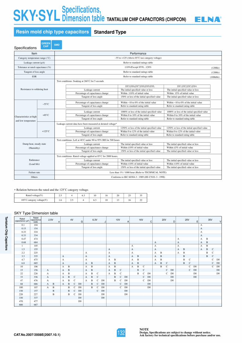
NOTEDesign, Specifications are subject to change without notice.Ask factory for technical specifications before purchase and/or use.CAT.No.2007/2008E(2007.10.1)
Specifications
Item Performance
Category temperature range (˚C)
Tolerance at rated capacitance (%)
Leakage current (µA)
Tangent of loss angle
ESR
Resistance to soldering heat
Characteristics at high
and low temperature
55˚C
85˚C
125˚C
Damp heat, steady state
(Humidity)
Endurance
(Load life)
Failure rate
)8991:3-101C5SIJ(9891:3-48306CEIotsmrofnoCsrehtO
Less than 1% / 1000 hour (Refer to TECHNICAL NOTE)
55 to 125 (Above 85˚C use category voltage)
Test conditions: Soaking at 260˚C for 5 seconds
Leakage current data have been measured at derated voltage*
Test conditions: Left at 40˚C under 90 to 95% RH for 500 hours
10%(Except SY9) , 20%
Refer to standard ratings table
(120Hz)
(120Hz)
(100kHz)
Leakage current
Percentage of capacitance change
Tangent of loss angle
Percentage of capacitance change
Tangent of loss angle
Leakage current
Percentage of capacitance change
Tangent of loss angle
Refer to standard ratings table
Refer to standard ratings table
The initial specified value or less
Within 10% of initial value
150% or less of the initial specified value
Within 10 to 0% of the initial value
Refer to standard rating table
Within 10 to 0% of the initial value
Refer to standard rating table
1000% or less of the initial specified value
Within 0 to 10% of the initial value
Refer to standard rating table
1000% or less of the initial specified value
Within 0 to 10% of the initial value
Refer to standard rating table
Leakage current
Percentage of capacitance change
Tangent of loss angle
1250% or less of the initial specified value
Within 0 to 12% of the initial value
Refer to standard rating table
1250% or less of the initial specified value
Within 0 to 12% of the initial value
Refer to standard rating table
Test conditions: Rated voltage applied at 85˚C for 2000 hours;
Leakage current
Percentage of capacitance change
Tangent of loss angle
The initial specified value or less
Within 10% of initial value
150% or less of the initial specified value
The initial specified value or less
Within 10% of initial value
The initial specified value or less
SY5,SY6,SY7,SY8,SY9,SYL
The initial specified value or less
Within 5% of initial value
The initial specified value or less
SY1,SY2,SY3,SY4
Leakage current
Percentage of capacitance change
Tangent of loss angle
The initial specified value or lessWithin 10% of initial value
150% or less of the initial specified value
The initial specified value or lessWithin 5% of initial value
The initial specified value or less
Relation between the rated and the 125˚C category voltage.
Rated voltage(V)
105˚C category voltage(V)
2.5 4 6.3 10 16 20 25 35
1.6 2.5 4 6.3 10 13 16 22
SKY Type Dimension table
GREENCAP SMD
0.1
0.15
0.22
0.33
0.47
0.68
1
1.5
2.2
3.3
4.7
6.8
10
15
22
33
47
68
100
150
220
330
470
680
104
154
224
334
474
684
105
155
225
335
475
685
106
156
226
336
476
686
107
157
227
337
477
687
Ratedcapacitance (µF)
Ratedcapacitance
code2.5V
e4V
G6.3V
J10V
A16V
C20V
D25V
E35V
V
A
A
A
A B
A B
A B
A B C
A B C
A B C D0
B C D0
B C D0
B C D0
D0
D0
A
A
A
A B
A B
A B
A B C
A B C
A B C D0
B C D0
B C D0
C D0
D0
D0
A
A
A
A B
A B
A B
A B C
A B C
B C D0
B C D0
C D0
C D0
D0
D0
A
A
A
A B
A B
A B
A B C
B C
B C D0
C D0
C D0
D0
D0
A
A
A
A B
A B
A B
A B C
B C
C D0
C D0
D0
D0
A
A
A
A B
A B
B
B C
B C
C D0
C D0
D0
D0
A
A
A
A
A B
A B
A B
A B C
B C
B C
C D0
C D0
C D0
D0
D0
A
A
A
A
A B
A B
B
B
Resin mold chip type capacitors Standard Type
TANTALUM CHIP CAPACITORS (CHIPCON) SKY.SYL Specifications,Dimension table ®
132
Tantalum C
hip Capacitors
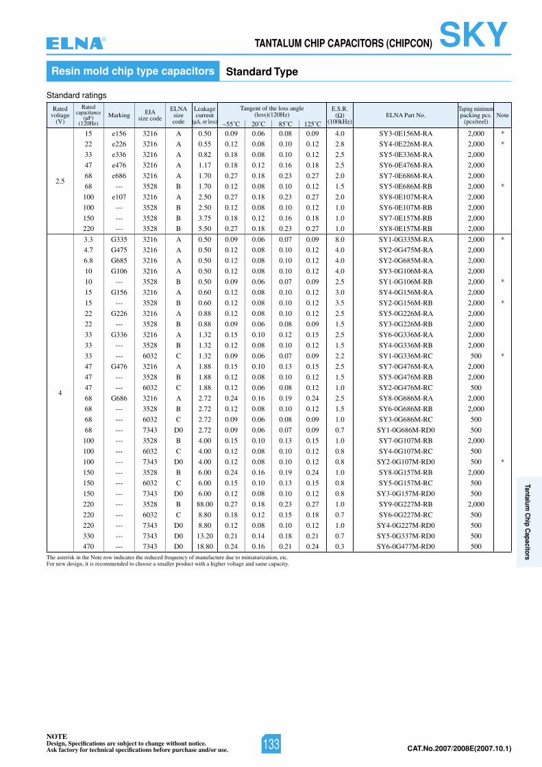
NOTEDesign, Specifications are subject to change without notice.Ask factory for technical specifications before purchase and/or use. CAT.No.2007/2008E(2007.10.1)
TANTALUM CHIP CAPACITORS (CHIPCON) SKYResin mold chip type capacitors Standard Type
Ratedvoltage
(V)
Ratedcapacitance
(µF)(120Hz)
Marking EIAsize code
ELNAsizecode
Leakagecurrent
(µA, or less)
Tangent of the loss angle(less)(120Hz)
E.S.R.( )
(100kHz)ELNA Part No.
Taping minimumpacking pcs.
(pcs/reel)Note
–55˚C 20˚C 85˚C 125˚C
2.5
15 e156 3216 A 0.50 0.09 0.06 0.08 0.09 4.0 SY3-0E156M-RA 2,000 *
22 e226 3216 A 0.55 0.12 0.08 0.10 0.12 2.8 SY4-0E226M-RA 2,000 *
33 e336 3216 A 0.82 0.18 0.08 0.10 0.12 2.5 SY5-0E336M-RA 2,000
47 e476 3216 A 1.17 0.18 0.12 0.16 0.18 2.5 SY6-0E476M-RA 2,000
68 e686 3216 A 1.70 0.27 0.18 0.23 0.27 2.0 SY7-0E686M-RA 2,000
68 --- 3528 B 1.70 0.12 0.08 0.10 0.12 1.5 SY5-0E686M-RB 2,000 *
100 e107 3216 A 2.50 0.27 0.18 0.23 0.27 2.0 SY8-0E107M-RA 2,000
100 --- 3528 B 2.50 0.12 0.08 0.10 0.12 1.0 SY6-0E107M-RB 2,000
150 --- 3528 B 3.75 0.18 0.12 0.16 0.18 1.0 SY7-0E157M-RB 2,000
220 --- 3528 B 5.50 0.27 0.18 0.23 0.27 1.0 SY8-0E157M-RB 2,000
4
3.3 G335 3216 A 0.50 0.09 0.06 0.07 0.09 8.0 SY1-0G335M-RA 2,000 *
4.7 G475 3216 A 0.50 0.12 0.08 0.10 0.12 4.0 SY2-0G475M-RA 2,000
6.8 G685 3216 A 0.50 0.12 0.08 0.10 0.12 4.0 SY2-0G685M-RA 2,000
10 G106 3216 A 0.50 0.12 0.08 0.10 0.12 4.0 SY3-0G106M-RA 2,000
10 --- 3528 B 0.50 0.09 0.06 0.07 0.09 2.5 SY1-0G106M-RB 2,000 *
15 G156 3216 A 0.60 0.12 0.08 0.10 0.12 3.0 SY4-0G156M-RA 2,000
15 --- 3528 B 0.60 0.12 0.08 0.10 0.12 3.5 SY2-0G156M-RB 2,000 *
22 G226 3216 A 0.88 0.12 0.08 0.10 0.12 2.5 SY5-0G226M-RA 2,000
22 --- 3528 B 0.88 0.09 0.06 0.08 0.09 1.5 SY3-0G226M-RB 2,000
33 G336 3216 A 1.32 0.15 0.10 0.12 0.15 2.5 SY6-0G336M-RA 2,000
33 --- 3528 B 1.32 0.12 0.08 0.10 0.12 1.5 SY4-0G336M-RB 2,000
33 --- 6032 C 1.32 0.09 0.06 0.07 0.09 2.2 SY1-0G336M-RC 500 *
47 G476 3216 A 1.88 0.15 0.10 0.13 0.15 2.5 SY7-0G476M-RA 2,000
47 --- 3528 B 1.88 0.12 0.08 0.10 0.12 1.5 SY5-0G476M-RB 2,000
47 --- 6032 C 1.88 0.12 0.06 0.08 0.12 1.0 SY2-0G476M-RC 500
68 G686 3216 A 2.72 0.24 0.16 0.19 0.24 2.5 SY8-0G686M-RA 2,000
68 --- 3528 B 2.72 0.12 0.08 0.10 0.12 1.5 SY6-0G686M-RB 2,000
68 --- 6032 C 2.72 0.09 0.06 0.08 0.09 1.0 SY3-0G686M-RC 500
68 --- 7343 D0 2.72 0.09 0.06 0.07 0.09 0.7 SY1-0G686M-RD0 500
100 --- 3528 B 4.00 0.15 0.10 0.13 0.15 1.0 SY7-0G107M-RB 2,000
100 --- 6032 C 4.00 0.12 0.08 0.10 0.12 0.8 SY4-0G107M-RC 500
100 --- 7343 D0 4.00 0.12 0.08 0.10 0.12 0.8 SY2-0G107M-RD0 500 *
150 --- 3528 B 6.00 0.24 0.16 0.19 0.24 1.0 SY8-0G157M-RB 2,000
150 --- 6032 C 6.00 0.15 0.10 0.13 0.15 0.8 SY5-0G157M-RC 500
150 --- 7343 D0 6.00 0.12 0.08 0.10 0.12 0.8 SY3-0G157M-RD0 500
220 --- 3528 B 88.00 0.27 0.18 0.23 0.27 1.0 SY9-0G227M-RB 2,000
220 --- 6032 C 8.80 0.18 0.12 0.15 0.18 0.7 SY6-0G227M-RC 500
220 --- 7343 D0 8.80 0.12 0.08 0.10 0.12 1.0 SY4-0G227M-RD0 500
330 --- 7343 D0 13.20 0.21 0.14 0.18 0.21 0.7 SY5-0G337M-RD0 500
470 --- 7343 D0 18.80 0.24 0.16 0.21 0.24 0.3 SY6-0G477M-RD0 500
Standard ratings
The asterisk in the Note row indicates the reduced frequency of manufacture due to miniaturization, etc.For new design, it is recommended to choose a smaller product with a higher voltage and same capacity.
®
133
Tantalum C
hip Capacitors
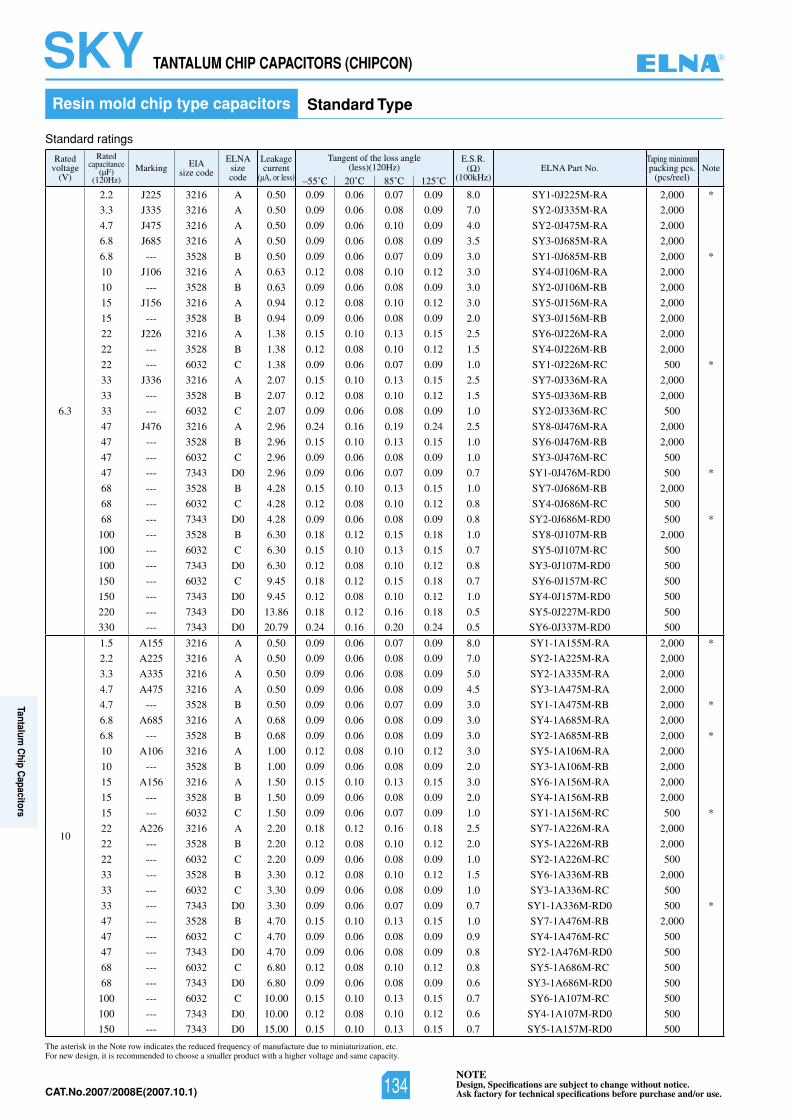
NOTEDesign, Specifications are subject to change without notice.Ask factory for technical specifications before purchase and/or use.CAT.No.2007/2008E(2007.10.1)
Ratedvoltage
(V)
Ratedcapacitance
(µF)(120Hz)
Marking EIAsize code
ELNAsizecode
Leakagecurrent
(µA, or less)
Tangent of the loss angle(less)(120Hz)
E.S.R.( )
(100kHz)ELNA Part No.
Taping minimumpacking pcs.
(pcs/reel)Note
–55˚C 20˚C 85˚C 125˚C
6.3
2.2 J225 3216 A 0.50 0.09 0.06 0.07 0.09 8.0 SY1-0J225M-RA 2,000 *
3.3 J335 3216 A 0.50 0.09 0.06 0.08 0.09 7.0 SY2-0J335M-RA 2,000
4.7 J475 3216 A 0.50 0.09 0.06 0.10 0.09 4.0 SY2-0J475M-RA 2,000
6.8 J685 3216 A 0.50 0.09 0.06 0.08 0.09 3.5 SY3-0J685M-RA 2,000
6.8 --- 3528 B 0.50 0.09 0.06 0.07 0.09 3.0 SY1-0J685M-RB 2,000 *
10 J106 3216 A 0.63 0.12 0.08 0.10 0.12 3.0 SY4-0J106M-RA 2,000
10 --- 3528 B 0.63 0.09 0.06 0.08 0.09 3.0 SY2-0J106M-RB 2,000
15 J156 3216 A 0.94 0.12 0.08 0.10 0.12 3.0 SY5-0J156M-RA 2,000
15 --- 3528 B 0.94 0.09 0.06 0.08 0.09 2.0 SY3-0J156M-RB 2,000
22 J226 3216 A 1.38 0.15 0.10 0.13 0.15 2.5 SY6-0J226M-RA 2,000
22 --- 3528 B 1.38 0.12 0.08 0.10 0.12 1.5 SY4-0J226M-RB 2,000
22 --- 6032 C 1.38 0.09 0.06 0.07 0.09 1.0 SY1-0J226M-RC 500 *
33 J336 3216 A 2.07 0.15 0.10 0.13 0.15 2.5 SY7-0J336M-RA 2,000
33 --- 3528 B 2.07 0.12 0.08 0.10 0.12 1.5 SY5-0J336M-RB 2,000
33 --- 6032 C 2.07 0.09 0.06 0.08 0.09 1.0 SY2-0J336M-RC 500
47 J476 3216 A 2.96 0.24 0.16 0.19 0.24 2.5 SY8-0J476M-RA 2,000
47 --- 3528 B 2.96 0.15 0.10 0.13 0.15 1.0 SY6-0J476M-RB 2,000
47 --- 6032 C 2.96 0.09 0.06 0.08 0.09 1.0 SY3-0J476M-RC 500
47 --- 7343 D0 2.96 0.09 0.06 0.07 0.09 0.7 SY1-0J476M-RD0 500 *
68 --- 3528 B 4.28 0.15 0.10 0.13 0.15 1.0 SY7-0J686M-RB 2,000
68 --- 6032 C 4.28 0.12 0.08 0.10 0.12 0.8 SY4-0J686M-RC 500
68 --- 7343 D0 4.28 0.09 0.06 0.08 0.09 0.8 SY2-0J686M-RD0 500 *
100 --- 3528 B 6.30 0.18 0.12 0.15 0.18 1.0 SY8-0J107M-RB 2,000
100 --- 6032 C 6.30 0.15 0.10 0.13 0.15 0.7 SY5-0J107M-RC 500
100 --- 7343 D0 6.30 0.12 0.08 0.10 0.12 0.8 SY3-0J107M-RD0 500
150 --- 6032 C 9.45 0.18 0.12 0.15 0.18 0.7 SY6-0J157M-RC 500
150 --- 7343 D0 9.45 0.12 0.08 0.10 0.12 1.0 SY4-0J157M-RD0 500
220 --- 7343 D0 13.86 0.18 0.12 0.16 0.18 0.5 SY5-0J227M-RD0 500
330 --- 7343 D0 20.79 0.24 0.16 0.20 0.24 0.5 SY6-0J337M-RD0 500
10
1.5 A155 3216 A 0.50 0.09 0.06 0.07 0.09 8.0 SY1-1A155M-RA 2,000 *
2.2 A225 3216 A 0.50 0.09 0.06 0.08 0.09 7.0 SY2-1A225M-RA 2,000
3.3 A335 3216 A 0.50 0.09 0.06 0.08 0.09 5.0 SY2-1A335M-RA 2,000
4.7 A475 3216 A 0.50 0.09 0.06 0.08 0.09 4.5 SY3-1A475M-RA 2,000
4.7 --- 3528 B 0.50 0.09 0.06 0.07 0.09 3.0 SY1-1A475M-RB 2,000 *
6.8 A685 3216 A 0.68 0.09 0.06 0.08 0.09 3.0 SY4-1A685M-RA 2,000
6.8 --- 3528 B 0.68 0.09 0.06 0.08 0.09 3.0 SY2-1A685M-RB 2,000 *
10 A106 3216 A 1.00 0.12 0.08 0.10 0.12 3.0 SY5-1A106M-RA 2,000
10 --- 3528 B 1.00 0.09 0.06 0.08 0.09 2.0 SY3-1A106M-RB 2,000
15 A156 3216 A 1.50 0.15 0.10 0.13 0.15 3.0 SY6-1A156M-RA 2,000
15 --- 3528 B 1.50 0.09 0.06 0.08 0.09 2.0 SY4-1A156M-RB 2,000
15 --- 6032 C 1.50 0.09 0.06 0.07 0.09 1.0 SY1-1A156M-RC 500 *
22 A226 3216 A 2.20 0.18 0.12 0.16 0.18 2.5 SY7-1A226M-RA 2,000
22 --- 3528 B 2.20 0.12 0.08 0.10 0.12 2.0 SY5-1A226M-RB 2,000
22 --- 6032 C 2.20 0.09 0.06 0.08 0.09 1.0 SY2-1A226M-RC 500
33 --- 3528 B 3.30 0.12 0.08 0.10 0.12 1.5 SY6-1A336M-RB 2,000
33 --- 6032 C 3.30 0.09 0.06 0.08 0.09 1.0 SY3-1A336M-RC 500
33 --- 7343 D0 3.30 0.09 0.06 0.07 0.09 0.7 SY1-1A336M-RD0 500 *
47 --- 3528 B 4.70 0.15 0.10 0.13 0.15 1.0 SY7-1A476M-RB 2,000
47 --- 6032 C 4.70 0.09 0.06 0.08 0.09 0.9 SY4-1A476M-RC 500
47 --- 7343 D0 4.70 0.09 0.06 0.08 0.09 0.8 SY2-1A476M-RD0 500
68 --- 6032 C 6.80 0.12 0.08 0.10 0.12 0.8 SY5-1A686M-RC 500
68 --- 7343 D0 6.80 0.09 0.06 0.08 0.09 0.6 SY3-1A686M-RD0 500
100 --- 6032 C 10.00 0.15 0.10 0.13 0.15 0.7 SY6-1A107M-RC 500
100 --- 7343 D0 10.00 0.12 0.08 0.10 0.12 0.6 SY4-1A107M-RD0 500
150 --- 7343 D0 15.00 0.15 0.10 0.13 0.15 0.7 SY5-1A157M-RD0 500
TANTALUM CHIP CAPACITORS (CHIPCON) SKYResin mold chip type capacitors Standard Type
Standard ratings
The asterisk in the Note row indicates the reduced frequency of manufacture due to miniaturization, etc.For new design, it is recommended to choose a smaller product with a higher voltage and same capacity.
®
134
Tantalum C
hip Capacitors
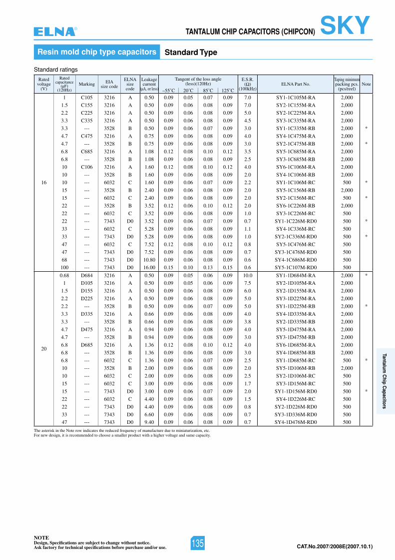
NOTEDesign, Specifications are subject to change without notice.Ask factory for technical specifications before purchase and/or use. CAT.No.2007/2008E(2007.10.1)
Ratedvoltage
(V)
Ratedcapacitance
(µF)(120Hz)
Marking EIAsize code
ELNAsizecode
Leakagecurrent
(µA, or less)
Tangent of the loss angle(less)(120Hz)
E.S.R.( )
(100kHz)ELNA Part No.
Taping minimumpacking pcs.
(pcs/reel)Note
–55˚C 20˚C 85˚C 125˚C
16
1 C105 3216 A 0.50 0.09 0.05 0.07 0.09 7.0 SY1-1C105M-RA 2,000
1.5 C155 3216 A 0.50 0.09 0.06 0.08 0.09 7.0 SY2-1C155M-RA 2,000
2.2 C225 3216 A 0.50 0.09 0.06 0.08 0.09 5.0 SY2-1C225M-RA 2,000
3.3 C335 3216 A 0.50 0.09 0.06 0.08 0.09 4.5 SY3-1C335M-RA 2,000
3.3 --- 3528 B 0.50 0.09 0.06 0.07 0.09 3.0 SY1-1C335M-RB 2,000 *
4.7 C475 3216 A 0.75 0.09 0.06 0.08 0.09 4.0 SY4-1C475M-RA 2,000
4.7 --- 3528 B 0.75 0.09 0.06 0.08 0.09 3.0 SY2-1C475M-RB 2,000 *
6.8 C685 3216 A 1.08 0.12 0.08 0.10 0.12 3.5 SY5-1C685M-RA 2,000
6.8 --- 3528 B 1.08 0.09 0.06 0.08 0.09 2.5 SY3-1C685M-RB 2,000
10 C106 3216 A 1.60 0.12 0.08 0.10 0.12 4.0 SY6-1C106M-RA 2,000
10 --- 3528 B 1.60 0.09 0.06 0.08 0.09 2.0 SY4-1C106M-RB 2,000
10 --- 6032 C 1.60 0.09 0.06 0.07 0.09 2.2 SY1-1C106M-RC 500 *
15 --- 3528 B 2.40 0.09 0.06 0.08 0.09 2.0 SY5-1C156M-RB 2,000
15 --- 6032 C 2.40 0.09 0.06 0.08 0.09 2.0 SY2-1C156M-RC 500 *
22 --- 3528 B 3.52 0.12 0.06 0.10 0.12 2.0 SY6-1C226M-RB 2,000
22 --- 6032 C 3.52 0.09 0.06 0.08 0.09 1.0 SY3-1C226M-RC 500
22 --- 7343 D0 3.52 0.09 0.06 0.07 0.09 0.7 SY1-1C226M-RD0 500 *
33 --- 6032 C 5.28 0.09 0.06 0.08 0.09 1.1 SY4-1C336M-RC 500
33 --- 7343 D0 5.28 0.09 0.06 0.08 0.09 1.0 SY2-1C336M-RD0 500 *
47 --- 6032 C 7.52 0.12 0.08 0.10 0.12 0.8 SY5-1C476M-RC 500
47 --- 7343 D0 7.52 0.09 0.06 0.08 0.09 0.7 SY3-1C476M-RD0 500
68 --- 7343 D0 10.80 0.09 0.06 0.08 0.09 0.6 SY4-1C686M-RD0 500
100 --- 7343 D0 16.00 0.15 0.10 0.13 0.15 0.6 SY5-1C107M-RD0 500
20
0.68 D684 3216 A 0.50 0.09 0.05 0.06 0.09 10.0 SY1-1D684M-RA 2,000 *
1 D105 3216 A 0.50 0.09 0.05 0.06 0.09 7.5 SY2-1D105M-RA 2,000
1.5 D155 3216 A 0.50 0.09 0.06 0.08 0.09 6.0 SY2-1D155M-RA 2,000
2.2 D225 3216 A 0.50 0.09 0.06 0.08 0.09 5.0 SY3-1D225M-RA 2,000
2.2 --- 3528 B 0.50 0.09 0.06 0.07 0.09 5.0 SY1-1D225M-RB 2,000 *
3.3 D335 3216 A 0.66 0.09 0.06 0.08 0.09 4.0 SY4-1D335M-RA 2,000
3.3 --- 3528 B 0.66 0.09 0.06 0.08 0.09 3.8 SY2-1D335M-RB 2,000
4.7 D475 3216 A 0.94 0.09 0.06 0.08 0.09 4.0 SY5-1D475M-RA 2,000
4.7 --- 3528 B 0.94 0.09 0.06 0.08 0.09 3.0 SY3-1D475M-RB 2,000
6.8 D685 3216 A 1.36 0.12 0.08 0.10 0.12 4.0 SY6-1D685M-RA 2,000
6.8 --- 3528 B 1.36 0.09 0.06 0.08 0.09 3.0 SY4-1D685M-RB 2,000
6.8 --- 6032 C 1.36 0.09 0.06 0.07 0.09 2.5 SY1-1D685M-RC 500 *
10 --- 3528 B 2.00 0.09 0.06 0.08 0.09 2.0 SY5-1D106M-RB 2,000
10 --- 6032 C 2.00 0.09 0.06 0.08 0.09 2.5 SY2-1D106M-RC 500
15 --- 6032 C 3.00 0.09 0.06 0.08 0.09 1.7 SY3-1D156M-RC 500
15 --- 7343 D0 3.00 0.09 0.06 0.07 0.09 2.0 SY1-1D156M-RD0 500 *
22 --- 6032 C 4.40 0.09 0.06 0.08 0.09 1.5 SY4-1D226M-RC 500
22 --- 7343 D0 4.40 0.09 0.06 0.08 0.09 0.8 SY2-1D226M-RD0 500
33 --- 7343 D0 6.60 0.09 0.06 0.08 0.09 0.7 SY3-1D336M-RD0 500
47 --- 7343 D0 9.40 0.09 0.06 0.08 0.09 0.7 SY4-1D476M-RD0 500
Resin mold chip type capacitors Standard Type
Standard ratings
The asterisk in the Note row indicates the reduced frequency of manufacture due to miniaturization, etc.For new design, it is recommended to choose a smaller product with a higher voltage and same capacity.
TANTALUM CHIP CAPACITORS (CHIPCON) SKY®
135
Tantalum C
hip Capacitors
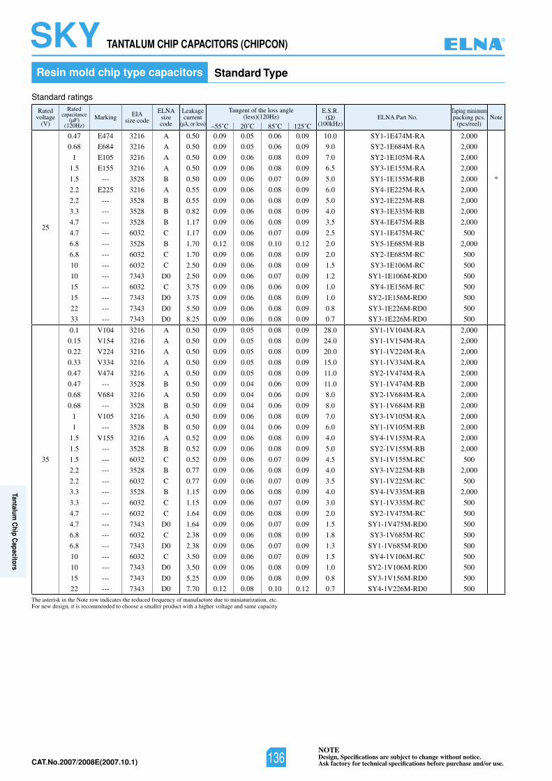
NOTEDesign, Specifications are subject to change without notice.Ask factory for technical specifications before purchase and/or use.CAT.No.2007/2008E(2007.10.1)
Ratedvoltage
(V)
Ratedcapacitance
(µF)(120Hz)
Marking EIAsize code
ELNAsizecode
Leakagecurrent
(µA, or less)
Tangent of the loss angle(less)(120Hz)
E.S.R.( )
(100kHz)ELNA Part No.
Taping minimumpacking pcs.
(pcs/reel)Note
–55˚C 20˚C 85˚C 125˚C
25
0.47 E474 3216 A 0.50 0.09 0.05 0.06 0.09 10.0 SY1-1E474M-RA 2,000
0.68 E684 3216 A 0.50 0.09 0.05 0.06 0.09 9.0 SY2-1E684M-RA 2,000
1 E105 3216 A 0.50 0.09 0.06 0.08 0.09 7.0 SY2-1E105M-RA 2,000
1.5 E155 3216 A 0.50 0.09 0.06 0.08 0.09 6.5 SY3-1E155M-RA 2,000
1.5 --- 3528 B 0.50 0.09 0.06 0.07 0.09 5.0 SY1-1E155M-RB 2,000 *
2.2 E225 3216 A 0.55 0.09 0.06 0.08 0.09 6.0 SY4-1E225M-RA 2,000
2.2 --- 3528 B 0.55 0.09 0.06 0.08 0.09 5.0 SY2-1E225M-RB 2,000
3.3 --- 3528 B 0.82 0.09 0.06 0.08 0.09 4.0 SY3-1E335M-RB 2,000
4.7 --- 3528 B 1.17 0.09 0.06 0.08 0.09 3.5 SY4-1E475M-RB 2,000
4.7 --- 6032 C 1.17 0.09 0.06 0.07 0.09 2.5 SY1-1E475M-RC 500
6.8 --- 3528 B 1.70 0.12 0.08 0.10 0.12 2.0 SY5-1E685M-RB 2,000
6.8 --- 6032 C 1.70 0.09 0.06 0.08 0.09 2.0 SY2-1E685M-RC 500
10 --- 6032 C 2.50 0.09 0.06 0.08 0.09 1.5 SY3-1E106M-RC 500
10 --- 7343 D0 2.50 0.09 0.06 0.07 0.09 1.2 SY1-1E106M-RD0 500
15 --- 6032 C 3.75 0.09 0.06 0.06 0.09 1.0 SY4-1E156M-RC 500
15 --- 7343 D0 3.75 0.09 0.06 0.08 0.09 1.0 SY2-1E156M-RD0 500
22 --- 7343 D0 5.50 0.09 0.06 0.08 0.09 0.8 SY3-1E226M-RD0 500
33 --- 7343 D0 8.25 0.09 0.06 0.08 0.09 0.7 SY3-1E226M-RD0 500
35
0.1 V104 3216 A 0.50 0.09 0.05 0.08 0.09 28.0 SY1-1V104M-RA 2,000
0.15 V154 3216 A 0.50 0.09 0.05 0.08 0.09 24.0 SY1-1V154M-RA 2,000
0.22 V224 3216 A 0.50 0.09 0.05 0.08 0.09 20.0 SY1-1V224M-RA 2,000
0.33 V334 3216 A 0.50 0.09 0.05 0.08 0.09 15.0 SY1-1V334M-RA 2,000
0.47 V474 3216 A 0.50 0.09 0.05 0.08 0.09 11.0 SY2-1V474M-RA 2,000
0.47 --- 3528 B 0.50 0.09 0.04 0.06 0.09 11.0 SY1-1V474M-RB 2,000
0.68 V684 3216 A 0.50 0.09 0.04 0.06 0.09 8.0 SY2-1V684M-RA 2,000
0.68 --- 3528 B 0.50 0.09 0.04 0.06 0.09 8.0 SY1-1V684M-RB 2,000
1 V105 3216 A 0.50 0.09 0.06 0.08 0.09 7.0 SY3-1V105M-RA 2,000
1 --- 3528 B 0.50 0.09 0.04 0.06 0.09 6.0 SY1-1V105M-RB 2,000
1.5 V155 3216 A 0.52 0.09 0.06 0.08 0.09 4.0 SY4-1V155M-RA 2,000
1.5 --- 3528 B 0.52 0.09 0.06 0.08 0.09 5.0 SY2-1V155M-RB 2,000
1.5 --- 6032 C 0.52 0.09 0.06 0.07 0.09 4.5 SY1-1V155M-RC 500
2.2 --- 3528 B 0.77 0.09 0.06 0.08 0.09 4.0 SY3-1V225M-RB 2,000
2.2 --- 6032 C 0.77 0.09 0.06 0.07 0.09 3.5 SY1-1V225M-RC 500
3.3 --- 3528 B 1.15 0.09 0.06 0.08 0.09 4.0 SY4-1V335M-RB 2,000
3.3 --- 6032 C 1.15 0.09 0.06 0.07 0.09 3.0 SY1-1V335M-RC 500
4.7 --- 6032 C 1.64 0.09 0.06 0.08 0.09 2.0 SY2-1V475M-RC 500
4.7 --- 7343 D0 1.64 0.09 0.06 0.07 0.09 1.5 SY1-1V475M-RD0 500
6.8 --- 6032 C 2.38 0.09 0.06 0.08 0.09 1.8 SY3-1V685M-RC 500
6.8 --- 7343 D0 2.38 0.09 0.06 0.07 0.09 1.3 SY1-1V685M-RD0 500
10 --- 6032 C 3.50 0.09 0.06 0.07 0.09 1.5 SY4-1V106M-RC 500
10 --- 7343 D0 3.50 0.09 0.06 0.08 0.09 1.0 SY2-1V106M-RD0 500
15 --- 7343 D0 5.25 0.09 0.06 0.08 0.09 0.8 SY3-1V156M-RD0 500
22 --- 7343 D0 7.70 0.12 0.08 0.10 0.12 0.7 SY4-1V226M-RD0 500
TANTALUM CHIP CAPACITORS (CHIPCON) SKYResin mold chip type capacitors Standard Type
Standard ratings
The asterisk in the Note row indicates the reduced frequency of manufacture due to miniaturization, etc.For new design, it is recommended to choose a smaller product with a higher voltage and same capacity.
®
136
Tantalum C
hip Capacitors
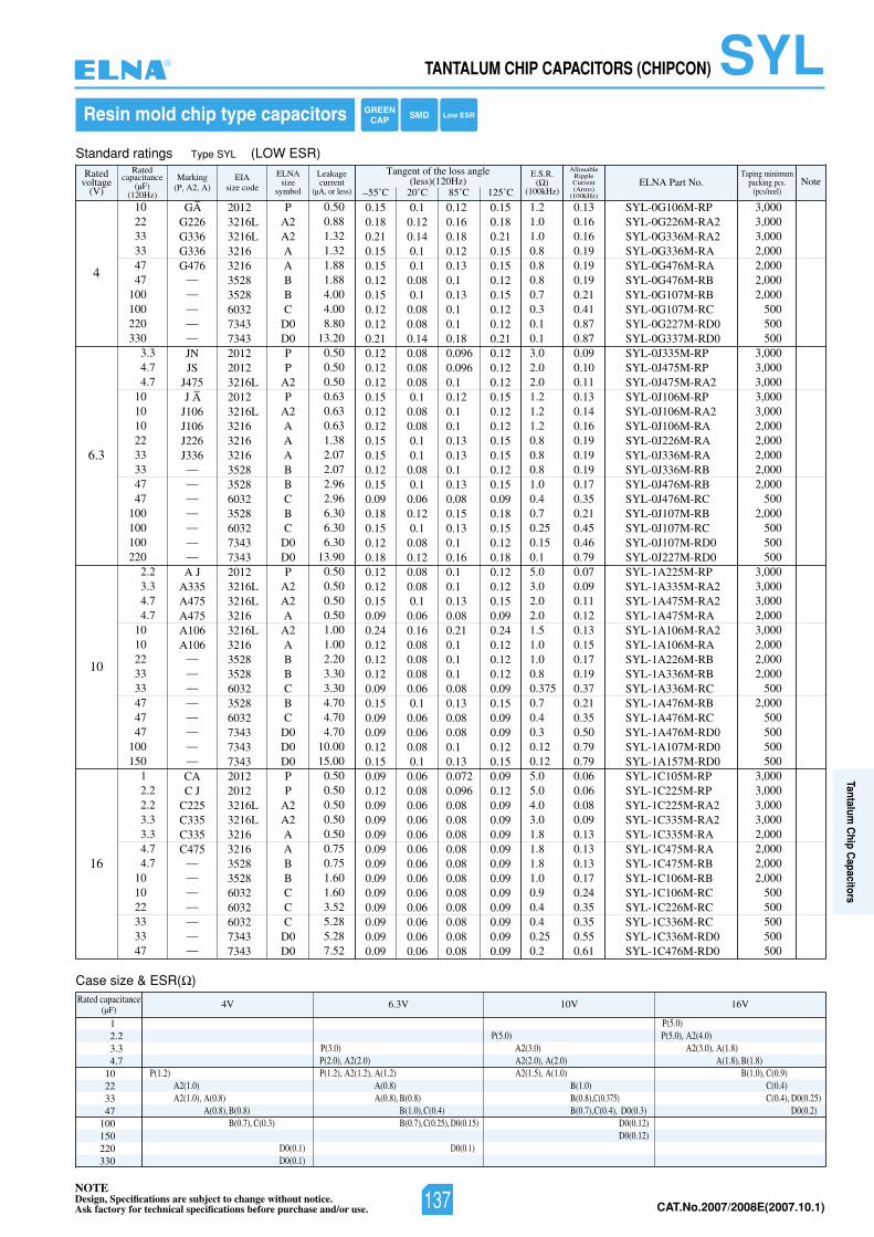
NOTEDesign, Specifications are subject to change without notice.Ask factory for technical specifications before purchase and/or use. CAT.No.2007/2008E(2007.10.1)
55˚C 20˚C 85˚C 125˚C
Tangent of the loss angle(less)(120Hz) Note
Ratedvoltage
(V)
Ratedcapacitance
(µF)(120Hz)
Marking(P, A2, A)
EIAsize code
ELNAsize
symbol
AllouableRippleCurrent(Arms)
(100kHz)
Leakagecurrent
(µA, or less)
E.S.R.( )
(100kHz)ELNA Part No.
Taping minimumpacking pcs.
(pcs/reel)
Standard ratings Type SYL (LOW ESR)
Case size & ESR( )
12.23.34.7
10223347
100150220330
V61V01V3.6V4Rated capacitance(µF)
P(1.2)A2(1.0)A2(1.0), A(0.8)
A(0.8), B(0.8)B(0.7), C(0.3)
D0(0.1)D0(0.1)
P(3.0)P(2.0), A2(2.0)P(1.2), A2(1.2), A(1.2)
A(0.8)A(0.8), B(0.8)
B(1.0),C(0.4)B(0.7),C(0.25), D0(0.15)
D0(0.1)
P(5.0)A2(3.0)A2(2.0), A(2.0)A2(1.5), A(1.0)
B(1.0)B(0.8),C(0.375)B(0.7),C(0.4), D0(0.3)
D0(0.12)D0(0.12)
P(5.0)P(5.0), A2(4.0)
A2(3.0), A(1.8)A(1.8), B(1.8)
B(1.0), C(0.9)C(0.4)C(0.4), D0(0.25)
D0(0.2)
4
6.3
10
16
GA–
G226G336G336G476
—————JNJS
J475J A
–
J106J106J226J336———————A J
A335A475A475A106A106
————————CAC J
C225C335C335C475
———————
20123216L3216L3216321635283528603273437343201220123216L20123216L321632163216352835286032352860327343734320123216L3216L32163216L321635283528603235286032734373437343201220123216L3216L321632163528352860326032603273437343
SYL-0G106M-RPSYL-0G226M-RA2SYL-0G336M-RA2SYL-0G336M-RASYL-0G476M-RASYL-0G476M-RBSYL-0G107M-RBSYL-0G107M-RCSYL-0G227M-RD0SYL-0G337M-RD0SYL-0J335M-RPSYL-0J475M-RPSYL-0J475M-RA2SYL-0J106M-RPSYL-0J106M-RA2SYL-0J106M-RASYL-0J226M-RASYL-0J336M-RASYL-0J336M-RBSYL-0J476M-RBSYL-0J476M-RCSYL-0J107M-RBSYL-0J107M-RCSYL-0J107M-RD0SYL-0J227M-RD0SYL-1A225M-RPSYL-1A335M-RA2SYL-1A475M-RA2SYL-1A475M-RASYL-1A106M-RA2SYL-1A106M-RASYL-1A226M-RBSYL-1A336M-RBSYL-1A336M-RCSYL-1A476M-RBSYL-1A476M-RCSYL-1A476M-RD0SYL-1A107M-RD0SYL-1A157M-RD0SYL-1C105M-RPSYL-1C225M-RPSYL-1C225M-RA2SYL-1C335M-RA2SYL-1C335M-RASYL-1C475M-RASYL-1C475M-RBSYL-1C106M-RBSYL-1C106M-RCSYL-1C226M-RCSYL-1C336M-RCSYL-1C336M-RD0SYL-1C476M-RD0
PA2A2AABBC
D0D0PP
A2P
A2AAABBCBC
D0D0P
A2A2AA2ABBCBC
D0D0D0PP
A2A2AABBCCC
D0D0
0.130.160.160.190.190.190.210.410.870.870.090.100.110.130.140.160.190.190.190.170.350.210.450.460.790.070.090.110.120.130.150.170.190.370.210.350.500.790.790.060.060.080.090.130.130.130.170.240.350.350.550.61
1.21.01.00.80.80.80.70.30.10.13.02.02.01.21.21.20.80.80.81.00.40.70.250.150.15.03.02.02.01.51.01.00.80.3750.70.40.30.120.125.05.04.03.01.81.81.81.00.90.40.40.250.2
3,0003,0003,0002,0002,0002,0002,000
500500500
3,0003,0003,0003,0003,0002,0002,0002,0002,0002,000
5002,000
500500500
3,0003,0003,0002,0003,0002,0002,0002,000
5002,000
500500500500
3,0003,0003,0003,0002,0002,0002,0002,000
500500500500500
102233334747
100100220330
3.34.74.7
1010102233334747
100100100220
2.23.34.74.7
1010223333474747
100150
12.22.23.33.34.74.7
101022333347
0.500.881.321.321.881.884.004.008.80
13.200.500.500.500.630.630.631.382.072.072.962.966.306.306.30
13.900.500.500.500.501.001.002.203.303.304.704.704.70
10.0015.000.500.500.500.500.500.750.751.601.603.525.285.287.52
0.15 0.1 0.12 0.150.18 0.12 0.16 0.180.21 0.14 0.18 0.210.15 0.1 0.12 0.150.15 0.1 0.13 0.150.12 0.08 0.1 0.120.15 0.1 0.13 0.150.12 0.08 0.1 0.120.12 0.08 0.1 0.120.21 0.14 0.18 0.210.12 0.08 0.096 0.120.12 0.08 0.096 0.120.12 0.08 0.1 0.120.15 0.1 0.12 0.150.12 0.08 0.1 0.120.12 0.08 0.1 0.120.15 0.1 0.13 0.150.15 0.1 0.13 0.150.12 0.08 0.1 0.120.15 0.1 0.13 0.150.09 0.06 0.08 0.090.18 0.12 0.15 0.180.15 0.1 0.13 0.150.12 0.08 0.1 0.120.18 0.12 0.16 0.180.12 0.08 0.1 0.120.12 0.08 0.1 0.120.15 0.1 0.13 0.150.09 0.06 0.08 0.090.24 0.16 0.21 0.240.12 0.08 0.1 0.120.12 0.08 0.1 0.120.12 0.08 0.1 0.120.09 0.06 0.08 0.090.15 0.1 0.13 0.150.09 0.06 0.08 0.090.09 0.06 0.08 0.090.12 0.08 0.1 0.120.15 0.1 0.13 0.150.09 0.06 0.072 0.090.12 0.08 0.096 0.120.09 0.06 0.08 0.090.09 0.06 0.08 0.090.09 0.06 0.08 0.090.09 0.06 0.08 0.090.09 0.06 0.08 0.090.09 0.06 0.08 0.090.09 0.06 0.08 0.090.09 0.06 0.08 0.090.09 0.06 0.08 0.090.09 0.06 0.08 0.090.09 0.06 0.08 0.09
Resin mold chip type capacitors GREENCAP SMD Low ESR
TANTALUM CHIP CAPACITORS (CHIPCON) SYL®
137
Tantalum C
hip Capacitors
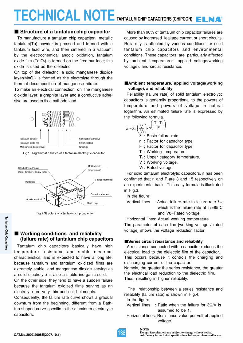
NOTEDesign, Specifications are subject to change without notice.Ask factory for technical specifications before purchase and/or use.CAT.No.2007/2008E(2007.10.1)
Structure of a tantalum chip capacitor
Tantalum chip capacitors basically have hightemperature resistance and stable electricalcharacteristics, and is expected to have a long life,because tantalum and tantalum oxidized films areextremely stable, and manganese dioxide serving asa solid electrolyte is also a stable inorganic solid.On the other side, they tend to have a sudden failurebecause the tantalum oxidized films serving as anelectrolyte are very thin and solid elements.Consequently, the failure rate curve shows a gradualdownturn from the beginning, different from a Bath-tub shaped curve specific to the aluminum electrolyticcapacitors.
To manufacture a tantalum chip capacitor, metallictantalum(Ta) powder is pressed and formed with atantalum lead wire, and then sintered in a vacuum;by the electrochemical anodic oxidation, tantalumoxide film (Ta2O5) is formed on the fired sur-face; thisoxide is used as the dielectric.On top of the dielectric, a solid manganese dioxidelayer(MnO2) is formed as the electrolyte through thethermal decomposition of manganese nitrate.To make an electrical connection on the manganesedioxide layer, a graphite layer and a conductive adhe-sive are used to fix a cathode lead.
More than 90% of tantalum chip capacitor failures arecaused by increased leakage current or short circuits.Reliability is affected by various conditions for solidtantalum chip capacitors and environmentalconditions. These capacitors are particularly affectedby ambient temperatures, applied voltage(workingvoltage), and circuit resistance.
Ambient temperature, applied voltage(workingvoltage), and reliability
Reliability (failure rate) of solid tantalum electrolyticcapacitors is generally proportional to the powers oftemperature and powers of voltage in naturallogarithm. An estimated failure rate is expressed bythe following formula.
: Basic failure rate.n : Factor for capacitor type.F : Factor for capacitor type.T : Working temperature.T0 : Upper category temperature.V : Working voltage.V0 : Rated voltage.
For solid tantalum electrolytic capacitors, it has beenconfirmed that n and F are 3 and 15 respectively onan experimental basis. This easy formula is illustratedin Fig.3.
In the figure;Vertical lines : Actual failure rate to failure rate 0,
which is the failure rate at T0=85˚Cand V0=Rated voltage
Horizontal lines: Actual working temperatureThe parameter of each line [working voltage / ratedvoltage] shows the voltage reduction factor.
Series circuit resistance and reliabilityA resistance connected with a capacitor reduces the
electrical load to the dielectric film of the capacitor.This occurs because it controls the charging anddischarging current of the capacitor.Namely, the greater the series resistance, the greaterthe electrical load reduction to the dielectric film.Thus, resulting in higher reliability.
The relationship between a series resistance andreliability (failure rate) is shown in Fig.4.
In the figure;Vertical lines : Ratio when the failure for 3 /V is
assumed to be 1.Horizontal lines: Resistance value per volt of applied
voltage.
Fig.1 Diagrammatic sketch of a tantalum electrolytic capacitor
Fig.2 Structure of a tantalum chip capacitor
Conductive adhesiveTantalum powder
Tantalum oxide film
Manganese dioxide layer
Silver coating
Graphite
Molded resin
(epoxy resin)
Cathode terminal
Capacitor element
Resin ring
Anode terminal
Weld point
Conductive adhesive
(silver powder + epoxy resin)
Working conditions and reliability(failure rate) of tantalum chip capacitors
V= 0 — • 2V0
T T0———F
TECHNICAL NOTE TANTALUM CHIP CAPACITORS (CHIPCON) ®
138
Tantalum C
hip Capacitors
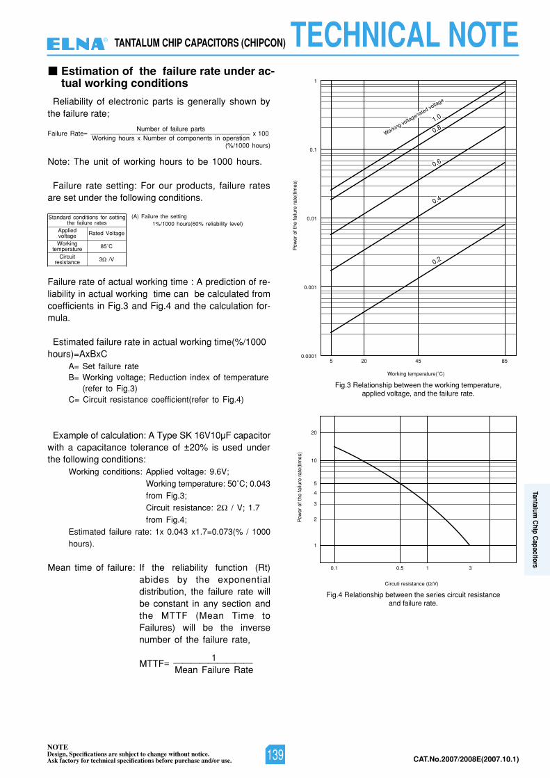
NOTEDesign, Specifications are subject to change without notice.Ask factory for technical specifications before purchase and/or use. CAT.No.2007/2008E(2007.10.1)
Estimation of the failure rate under ac-tual working conditions
Reliability of electronic parts is generally shown bythe failure rate;
Note: The unit of working hours to be 1000 hours.
Failure rate setting: For our products, failure ratesare set under the following conditions.
Failure rate of actual working time : A prediction of re-liability in actual working time can be calculated fromcoefficients in Fig.3 and Fig.4 and the calculation for-mula.
Estimated failure rate in actual working time(%/1000hours)=AxBxC
A= Set failure rateB= Working voltage; Reduction index of temperature
(refer to Fig.3)C= Circuit resistance coefficient(refer to Fig.4)
Example of calculation: A Type SK 16V10µF capacitorwith a capacitance tolerance of ±20% is used underthe following conditions:
Working conditions: Applied voltage: 9.6V;Working temperature: 50˚C; 0.043from Fig.3;Circuit resistance: 2 / V; 1.7from Fig.4;
Estimated failure rate: 1x 0.043 x1.7=0.073(% / 1000hours).
Mean time of failure: If the reliability function (Rt)abides by the exponentialdistribution, the failure rate willbe constant in any section andthe MTTF (Mean Time toFailures) will be the inversenumber of the failure rate,
MTTF= —————————
Number of failure partsFailure Rate= ——————————————————————— x 100
Working hours x Number of components in operation(%/1000 hours)
1Mean Failure Rate
Rated Voltage
85˚C
3 /V
Standard conditions for settingthe failure rates
(A) Failure the setting1%/1000 hours(60% reliability level)
AppliedvoltageWorking
temperatureCircuit
resistance
1
0.1
0.01
0.001
0.00015854025
Pow
er o
f the
failu
rera
te(t
imes
)
Working temperature(˚C)
0.2
0.4
0.6
0.81.0
Working voltage/rated voltage
Fig.3 Relationship between the working temperature,applied voltage, and the failure rate.
Fig.4 Relationship between the series circuit resistanceand failure rate.
20
10
5
4
3
2
1
315.01.0
Pow
er o
f the
failu
rera
te(t
imes
)
Circuti resistance ( /V)
TANTALUM CHIP CAPACITORS (CHIPCON) TECHNICAL NOTE®
139
Tantalum C
hip Capacitors
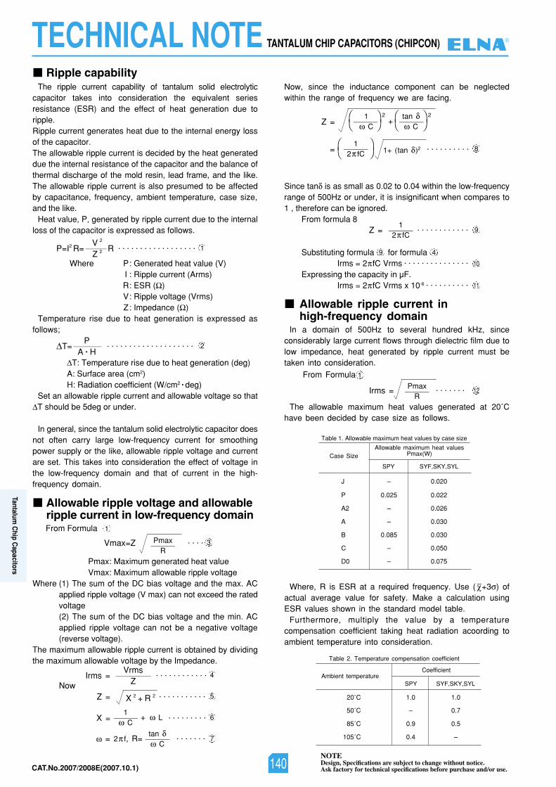
NOTEDesign, Specifications are subject to change without notice.Ask factory for technical specifications before purchase and/or use.CAT.No.2007/2008E(2007.10.1)
Ripple capabilityThe ripple current capability of tantalum solid electrolytic
capacitor takes into consideration the equivalent seriesresistance (ESR) and the effect of heat generation due toripple.Ripple current generates heat due to the internal energy lossof the capacitor.The allowable ripple current is decided by the heat generateddue the internal resistance of the capacitor and the balance ofthermal discharge of the mold resin, lead frame, and the like.The allowable ripple current is also presumed to be affectedby capacitance, frequency, ambient temperature, case size,and the like.
Heat value, P, generated by ripple current due to the internalloss of the capacitor is expressed as follows.
Where P: Generated heat value (V)I : Ripple current (Arms)R: ESR ( )V: Ripple voltage (Vrms)Z: Impedance ( )
Temperature rise due to heat generation is expressed asfollows;
T: Temperature rise due to heat generation (deg) A: Surface area (cm2)H: Radiation coefficient (W/cm2 • deg)
Set an allowable ripple current and allowable voltage so thatT should be 5deg or under.
In general, since the tantalum solid electrolytic capacitor doesnot often carry large low-frequency current for smoothingpower supply or the like, allowable ripple voltage and currentare set. This takes into consideration the effect of voltage inthe low-frequency domain and that of current in the high-frequency domain.
From Formula
Pmax: Maximum generated heat valueVmax: Maximum allowable ripple voltage
Where (1) The sum of the DC bias voltage and the max. ACapplied ripple voltage (V max) can not exceed the ratedvoltage(2) The sum of the DC bias voltage and the min. ACapplied ripple voltage can not be a negative voltage(reverse voltage).
The maximum allowable ripple current is obtained by dividingthe maximum allowable voltage by the Impedance.
Now
Now, since the inductance component can be neglectedwithin the range of frequency we are facing.
Since tan is as small as 0.02 to 0.04 within the low-frequencyrange of 500Hz or under, it is insignificant when compares to1 , therefore can be ignored.
From formula 8
Substituting formula for formula Irms = 2 fC Vrms • • • • • • • • • • • • • • •
Expressing the capacity in µF.Irms = 2 fC Vrms x 10-6 • • • • • • • • • •
In a domain of 500Hz to several hundred kHz, sinceconsiderably large current flows through dielectric film due tolow impedance, heat generated by ripple current must betaken into consideration.
The allowable maximum heat values generated at 20˚Chave been decided by case size as follows.
Where, R is ESR at a required frequency. Use ( +3 ) ofactual average value for safety. Make a calculation usingESR values shown in the standard model table.
Furthermore, multiply the value by a temperaturecompensation coefficient taking heat radiation acoording toambient temperature into consideration.
Allowable ripple voltage and allowableripple current in low-frequency domain
Allowable ripple current inhigh-frequency domain
V 2
P=I2 R= ——— R • • • • • • • • • • • • • • • • • •
Z 2
Vmax=Z • • • •
From Formula
1
1
PT= ———— • • • • • • • • • • • • • • • • • • • •
A • H2
3Pmax———
R
VrmsIrms = ————— • • • • • • • • • • • •
Z
Z = • • • • • • • • • • •
X = • • • • • • • • •
= • • • • • • •
X 2 + R 2
1——— + L
C
tan2 f, R= ———
C
4
5
6
7
Z = • • • • • • • • • • • • 9
10
11
9 4
1———2 fC
8
1
Irms = • • • • • • • 12Pmax
———R
Case Size
P
A2
A
B
C
D0
Allowable maximum heat valuesPmax(W)
0.025
–
–
0.085
–
–
0.022
0.026
J – 0.020
0.030
0.030
0.050
0.075
Table 1. Allowable maximum heat values by case size
Ambient temperature
20˚C
85˚C
105˚C
SPY
1.0
50˚C –
0.9
0.4
SYF,SKY,SYL
SPY SYF,SKY,SYL
Coefficient
1.0
0.7
0.5
–
Table 2. Temperature compensation coefficient
Z =
= • • • • • • • • • •
1 tan———
2+ ———
2
C C
1+ tan 21
———2 fC
TECHNICAL NOTE TANTALUM CHIP CAPACITORS (CHIPCON) ®
140
Tantalum C
hip Capacitors
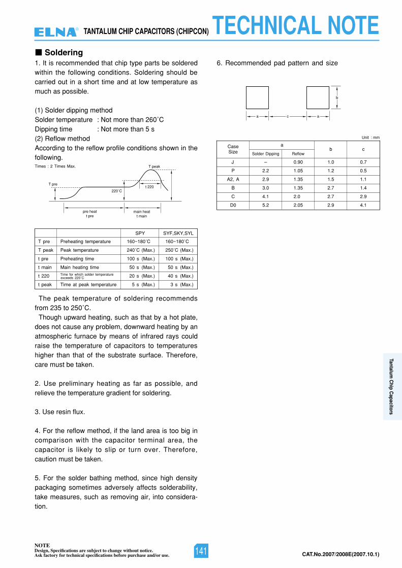
NOTEDesign, Specifications are subject to change without notice.Ask factory for technical specifications before purchase and/or use. CAT.No.2007/2008E(2007.10.1)
Soldering1. It is recommended that chip type parts be solderedwithin the following conditions. Soldering should becarried out in a short time and at low temperature asmuch as possible.
(1) Solder dipping methodSolder temperature : Not more than 260˚CDipping time : Not more than 5 s(2) Reflow methodAccording to the reflow profile conditions shown in thefollowing.
The peak temperature of soldering recommendsfrom 235 to 250˚C.
Though upward heating, such as that by a hot plate,does not cause any problem, downward heating by anatmospheric furnace by means of infrared rays couldraise the temperature of capacitors to temperatureshigher than that of the substrate surface. Therefore,care must be taken.
2. Use preliminary heating as far as possible, andrelieve the temperature gradient for soldering.
3. Use resin flux.
4. For the reflow method, if the land area is too big incomparison with the capacitor terminal area, thecapacitor is likely to slip or turn over. Therefore,caution must be taken.
5. For the solder bathing method, since high densitypackaging sometimes adversely affects solderability,take measures, such as removing air, into considera-tion.
6. Recommended pad pattern and size
T pre
T peak
t pre
t main
t 220
t peak
Preheating temperature
Peak temperature
Preheating time
Main heating time
Time at peak temperature
Time for which solder temperatureexceeds 220˚C
160~180
SPY SYF,SKY,SYL
˚C
240˚C (Max.)
100 s (Max.)
50 s (Max.)
20 s (Max.)
5 s (Max.)
160~180˚C
250˚C (Max.)
100 s (Max.)
50 s (Max.)
40 s (Max.)
3 s (Max.)
main heatt main
220˚Ct 220
T peak
pre heatt pre
T pre
CaseSize b c
P
A2, A
B
C
D0
a
Solder Dipping Reflow
2.2 1.05 1.2 0.5
J – 0.90 1.0 0.7
2.9 1.35 1.5 1.1
3.0 1.35 2.7 1.4
4.1 2.0 2.7 2.9
5.2 2.05 2.9 4.1
b
aca
Unit : mm
Times : 2 Times Max.
TANTALUM CHIP CAPACITORS (CHIPCON) TECHNICAL NOTE®
141
Tantalum C
hip Capacitors
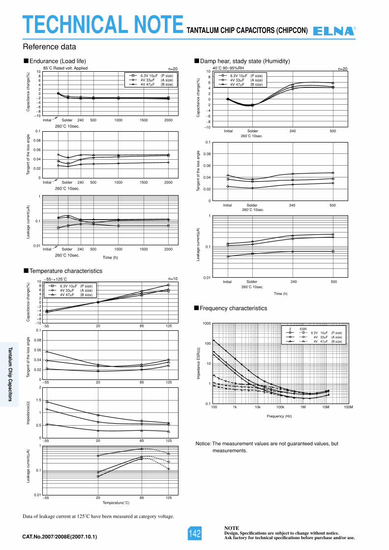
NOTEDesign, Specifications are subject to change without notice.Ask factory for technical specifications before purchase and/or use.CAT.No.2007/2008E(2007.10.1)
Notice: The measurement values are not guaranteed values, butmeasurements.
Endurance (Load life)
0
0.1
0.08
0.06
0.04
0.02
0
1
0.1
0.01
10864202468
10
2468
10
2468
10200015001000500240SolderInitial
260˚C 10sec.
85˚C Rated volt. Applied
55~+125˚C
40˚C 90~95%RHn=20
n=10
Cap
acita
nce
chan
ge(%
)
Cap
acita
nce
chan
ge(%
)
Tang
ent o
f the
loss
ang
leC
apac
itanc
e ch
ange
(%)
T ang
ent o
f the
loss
ang
leIm
peda
nce(
)
Impe
danc
e E
SR
()
Temperature characteristics
Frequency characteristics
Damp hear, stady state (Humidity)
200015001000500240SolderInitial
260˚C 10sec.
200015001000500240SolderInitial
260˚C 10sec. Time (h)
Temperature(˚C)
0
2
4
6
8
10
2
4
6
8
10500240SolderInitial
260˚C 10sec.
n=20
0.1
0.08
0.06
0.04
0.02
0Ta
ngen
t of t
he lo
ss a
ngle
500240SolderInitial260˚C 10sec.
1
0.1
0.01
0.1
1
10
100
1000
100 1k 10k 100k 1M 10M 100M
Leak
age
curr
ent(
A)
500240SolderInitial260˚C 10sec.
Time (h)
Frequency (Hz)
0
0.02
0.04
0.06
0.08
0.1
5215802
0
0.5
1
1.5
2
52158021
0.1
0.015215802
55
5215802
6.3V 10 F (P size) 4V 33 F (A size) 4V 47 F (B size)
Z ESR
Leak
age
curr
ent(
A)
Leak
age
curr
ent(
A)
6.3V 10 F (P size)4V 33 F (A size)4V 47 F (B size)
6.3V 10 F (P size)4V 33 F (A size)4V 47 F (B size)
6.3V 10 F (P size)4V 33 F (A size)4V 47 F (B size)
55
55
55
Data of leakage current at 125˚C have been measured at category voltage.
Reference data
TECHNICAL NOTE TANTALUM CHIP CAPACITORS (CHIPCON) ®
142
Tantalum C
hip Capacitors
NOTEDesign, Specifications are subject to change without notice.Ask factory for technical specifications before purchase and/or use. CAT.No.2007/2008E(2007.10.1)
Electric Double Layer Capacitors“DYNACAP”, “POWERCAP”
List of Contents
1. Type List and Systematized Classification for Electric DoubleLayer Capacitors • • • • • • • • • • • • • • • • • • • • • • • • • • • • • • • • • • • • 144
2. Cautions for Using Electric Double Layer Capacitors • • • • • • • 1473. Lead Forming and Taping • • • • • • • • • • • • • • • • • • • • • • • • • • • • • 1494. Specifications for Electric Double Layer Capacitors by Series • 1505. Technical Note for Electric Double Layer Capacitors • • • • • • • • 1646. Presentation of Series and Parallel Connection Pack • • • • • • • 1677. Technical data for Electric Double Layer Capacitors • • • • • • • • 168
CAT.No.2007/2008E(2007.10.1)143
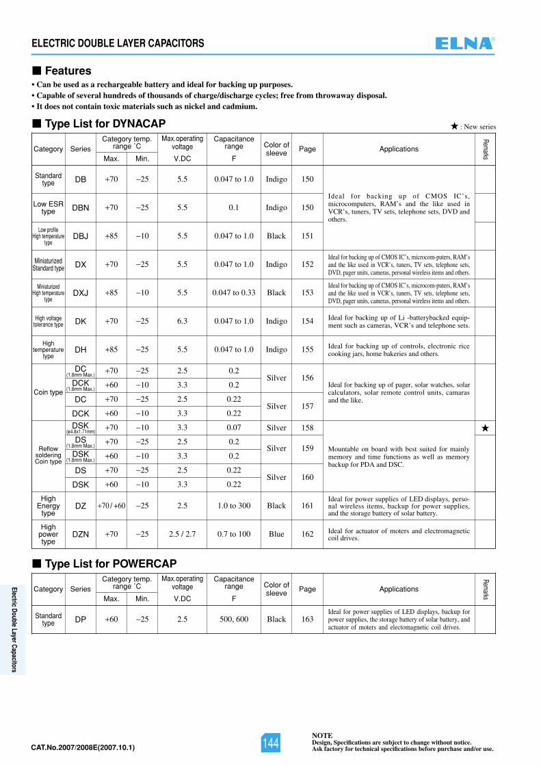
NOTEDesign, Specifications are subject to change without notice.Ask factory for technical specifications before purchase and/or use.CAT.No.2007/2008E(2007.10.1)
ELECTRIC DOUBLE LAYER CAPACITORS
Features• Can be used as a rechargeable battery and ideal for backing up purposes.• Capable of several hundreds of thousands of charge/discharge cycles; free from throwaway disposal.• It does not contain toxic materials such as nickel and cadmium.
Type List for DYNACAP
Standardtype
Low ESRtype
Low profileHigh temperature
type
MiniaturizedStandard type
MiniaturizedHigh temperature
type
High voltagetolerance type
Hightemperature
type
Coin type
ReflowsolderingCoin type
HighEnergy
type
Highpowertype
Ideal for backing up of CMOS IC’s,microcomputers, RAM’s and the like used inVCR’s, tuners, TV sets, telephone sets, DVD andothers.
Ideal for backing up of CMOS IC’s, microcom-puters, RAM’sand the like used in VCR’s, tuners, TV sets, telephone sets,DVD, pager units, cameras, personal wireless items and others.
Ideal for backing up of CMOS IC’s, microcom-puters, RAM’sand the like used in VCR’s, tuners, TV sets, telephone sets,DVD, pager units, cameras, personal wireless items and others.
Ideal for backing up of Li -batterybacked equip-ment such as cameras, VCR’s and telephone sets.
Ideal for backing up of controls, electronic ricecooking jars, home bakeries and others.
Ideal for backing up of pager, solar watches, solarcalculators, solar remote control units, camarasand the like.
Mountable on board with best suited for mainlymemory and time functions as well as memorybackup for PDA and DSC.
Ideal for power supplies of LED displays, perso-nal wireless items, backup for power supplies,and the storage battery of solar battery.
Ideal for actuator of moters and electromagneticcoil drives.
70 25 5.5 0.047 to 1.0 Indigo 150
70 25 5.5 0.1 Indigo 150
70 25 5.5 0.047 to 1.0 Indigo 152
85 10 5.5 0.047 to 0.33 Black 153
70 25 6.3 0.047 to 1.0 Indigo 154
85 25 5.5 0.047 to 1.0 Indigo 155
70 25 2.5 0.2Silver 156
60 10 3.3 0.2
70 25 2.5 0.22Silver 157
60 10 3.3 0.22
70 25 2.5 0.22Silver 160
60 10 3.3 0.22
70 / +60 25 2.5 1.0 to 300 Black 161
70 25 2.5 / 2.7 0.7 to 100 Blue 162
Category Series
DB
DBN
85 10 5.5 0.047 to 1.0 Black 151DBJ
DX
DXJ
DK
DH
DC(1.8mm Max.)
DC
DCK(1.8mm Max.)
70 10 3.3 0.07
Silver 159
Silver 158
60 10 3.3 0.2
DSK(ø4.8x1.71mm)
70 25 2.5 0.2DS(1.8mm Max.)
DSK(1.8mm Max.)
DCK
DS
DZ
DZN
DSK
Category temp.range ˚C
Max. Min. V.DC F
Max.operatingvoltage
Capacitancerange Color of
sleeve Page Applications
Remarks
Type List for POWERCAP
Standardtype
Ideal for power supplies of LED displays, backup forpower supplies, the storage battery of solar battery, andactuator of moters and electomagnetic coil drives.
60 25 2.5 500, 600 Black 163
Category Series
DP
Category temp.range ˚C
Max. Min. V.DC F
Max.operatingvoltage
Capacitancerange Color of
sleeve Page Applications
Remarks
: New series
®
144
Electric Double Layer Capacitors
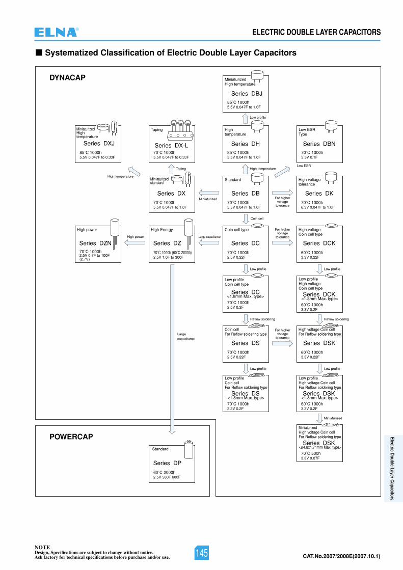
NOTEDesign, Specifications are subject to change without notice.Ask factory for technical specifications before purchase and/or use. CAT.No.2007/2008E(2007.10.1)
ELECTRIC DOUBLE LAYER CAPACITORS
Systematized Classification of Electric Double Layer Capacitors
DYNACAP
POWERCAP
70˚C 1000h5.5V 0.047F to 0.33F
Taping
Taping
Series DX-L
70˚C 1000h5.5V 0.047F to 1.0F
Miniaturizedstandard
MiniaturizedSeries DX
70˚C 1000h (60˚C 2000h)2.5V 1.0F to 300F
High Energy
Large capacitance
Largecapacitance
For highervoltage
tolerance
For highervoltage
tolerance
For highervoltage
tolerance
Series DZ
85˚C 1000h5.5V 0.047F to 1.0F
High temperature
Low profile
High temperature
Hightemperature
Series DH
70˚C 1000h5.5V 0.047F to 1.0F
Coin cell
Standard
Series DB
70˚C 1000h2.5V 0.22F
Low profile
Coin cell type
Series DC
70˚C 1000h2.5V 0.22F
Coin cellFor Reflow soldering type
Series DS
Reflow soldering
Low profile
70˚C 1000h6.3V 0.047F to 1.0F
Series DK
Series DCK
Series DBN
60˚C 1000h3.3V 0.22F
60˚C 1000h3.3V 0.22F
High voltage Coin cellFor Reflow soldering type
High voltageCoin cell type
High voltagetolerance
Series DSK
85˚C 1000h5.5V 0.047F to 1.0F
MiniaturizedHigh temperature
Series DBJ
70˚C 1000h5.5V 0.1F
Low ESR
Low ESRType
70˚C 1000h2.5V 0.2F
Low profileCoin cell type
60˚C 2000h2.5V 500F 600F
Series DP
70˚C 1000h2.5V 0.7F to 100F(2.7V)
High power
High power
Series DZN
85˚C 1000h5.5V 0.047F to 0.33F
MiniaturizedHightemperature
Series DXJ
Standard
60˚C 1000h3.3V 0.2F
Low profileHigh voltageCoin cell type
Series DCK<1.8mm Max. type>
Series DC<1.8mm Max. type>
Reflow soldering
Low profile
60˚C 1000h3.3V 0.2F
Low profileHigh voltage Coin cellFor Reflow soldering type
Series DSK<1.8mm Max. type>
Miniaturized
70˚C 500h3.3V 0.07F
MiniaturizedHigh voltage Coin cellFor Reflow soldering type
Series DSK<ø4.8x1.71mm Max. type>
Low profile
70˚C 1000h3.3V 0.2F
Low profileCoin cellFor Reflow soldering type
Series DS<1.8mm Max. type>
®
145
Electric Double Layer Capacitors
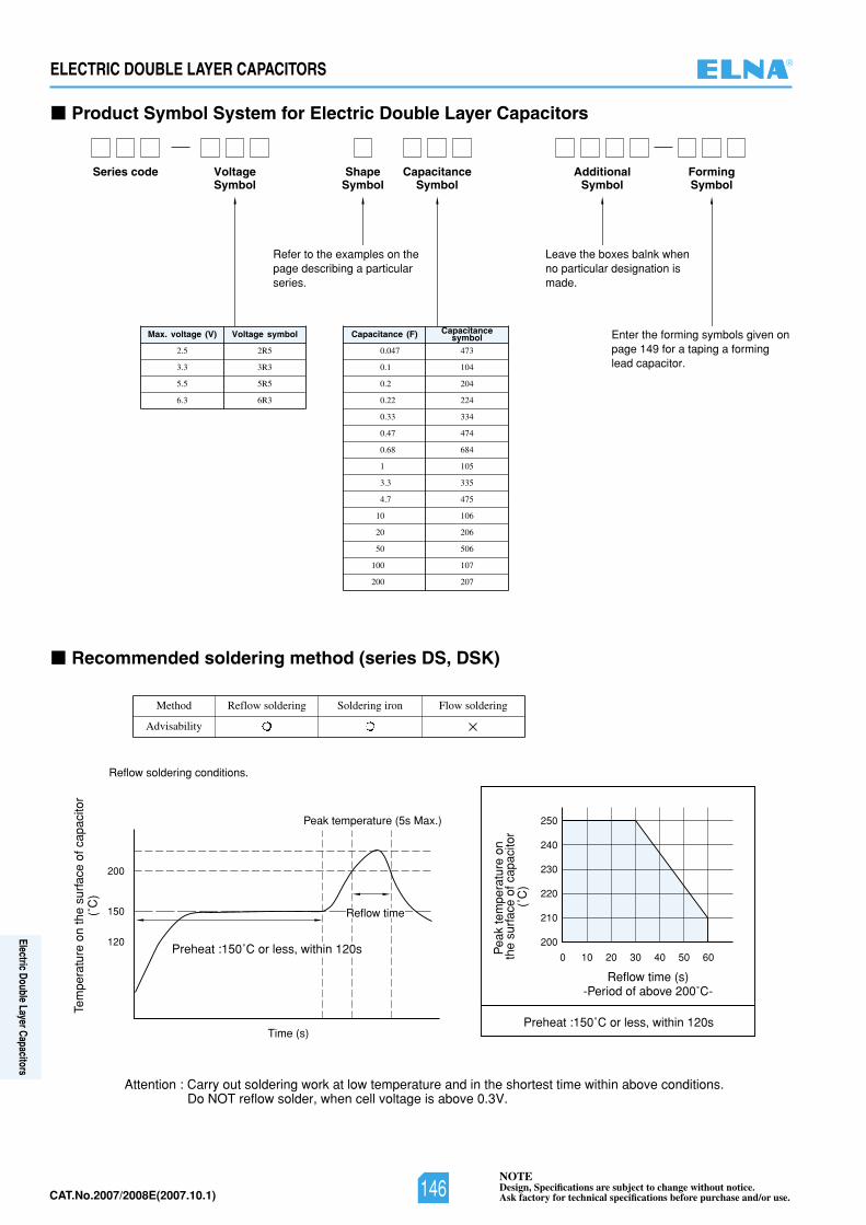
NOTEDesign, Specifications are subject to change without notice.Ask factory for technical specifications before purchase and/or use.CAT.No.2007/2008E(2007.10.1)
Product Symbol System for Electric Double Layer Capacitors
Reflow time
Time (s)
120
150
200
200
0 10 20 30 40 50 60
210
220
230
240
250Peak temperature (5s Max.)
Preheat :150˚C or less, within 120s
Preheat :150˚C or less, within 120s
Tem
pera
ture
on
the
surf
ace
of c
apac
itor
Pea
k te
mpe
ratu
re o
n th
e su
rfac
e of
cap
acito
r
Reflow time (s)-Period of above 200˚C-
(˚C
)
(˚C
)
Reflow soldering conditions.
Recommended soldering method (series DS, DSK)
Series code FormingSymbol
VoltageSymbol
ShapeSymbol
CapacitanceSymbol
AdditionalSymbol
Refer to the examples on thepage describing a particularseries.
Leave the boxes balnk whenno particular designation ismade.
Enter the forming symbols given onpage 149 for a taping a forminglead capacitor.
2.5 2R5
3.3 3R3
5.5 5R5
6.3 6R3
Max. voltage (V) Voltage symbol
Method
Advisability
Reflow soldering Soldering iron Flow soldering
0.047 473
0.1 104
0.2 204
0.22 224
0.33 334
0.47 474
0.68 684
1 105
3.3 335
4.7 475
10 106
20 206
50 506
100 107
200 207
Capacitance (F) Capacitancesymbol
Attention : Carry out soldering work at low temperature and in the shortest time within above conditions.Do NOT reflow solder, when cell voltage is above 0.3V.
ELECTRIC DOUBLE LAYER CAPACITORS ®
146
Electric Double Layer Capacitors
NOTEDesign, Specifications are subject to change without notice.Ask factory for technical specifications before purchase and/or use. CAT.No.2007/2008E(2007.10.1)
ELECTRIC DOUBLE LAYER CAPACITORS
Cautions for Using Electric Double Layer Capacitor (DYNACAP, POWERCAP)
1. Electric double layer capacitors (EDLC) use aconductive organic electrolyte.
The use at excessive mounting temperature orexceeding the upper category temperature cancause the electrolyte to leak. Especially, coin andmultilayer coin types (DB, DBN, DBJ, DX, DXJ, DX-L, DH, DK, DC, DCK, DS, and DSK series)excluding the DZ and DZN series use a low elasticplastic as the sealant in the cell construction likecoin batteries; therefore, avoid using suchcapacitors in the vicnity of automotive equipmentwith steep temperature change, and heatingelement such as motor, relay, transformer, powerIC, etc. because of the risk of leakage of electrolyte.
2. Since EDLC is polarized, do not apply areversed voltage.
EDLC is polarized. If a reversed voltage is appliedfor a long time, the leakage current will increaseabruptly, which may cause a decrease in thecapacity, an increase in the internal resistance, andcausing leakage or damage to the product in somecases.
3. Do not apply any voltage higher than theoperating maximum voltage (this means the surgevoltage in the case of short-time charge).
If an overvoltage is applied to the product, theleakage current will increase abruptly and theproduct will become overheated, which may causea decrease in the capacity, an increase in theinternal resistance, and causing leakage or damageto the product in some cases.
4. Do not use smoothing a power supply (forabsorbing its ripple).
Since the internal resistance of EDLC is high, theproduct will be overheated if it is used for smoothinga power supply (for absorbing its ripple), which maycause a decrease in the capacity. an increase inthe internal resistance, and causing leakage ordamage to the product in some cases.
5. Do not use in a circuit where quick charge anddischarge are repeated very often.
In a circuit where quick charge and discharge arerepeated very often, the product will becomeoverheated, which may cause a decrease in thecapacity, an increase in the internal resistance, andcausing leakage or damage to the product in somecases.Reduce the charge and discharge currents whileselecting a product with low internal resistance, andmake sure that the product surface temperaturedoes not rise.
6. EDLC life depends heavily on the ambienttemperature.
The lifetime of EDLC is seriously affected bychange in ambient temperature. lf the temperatureis lowered by 10˚C, the lifetime will be approxi-mately doubled. Therefore, the product should beused at a temperature lower than the guaranteedmaximum value for maximum life.
If the capacitor is used at a temperatureexceeding its maximum guaranteed temperature,not only is its life shortened, but increased vapor
pressure of electrolyte or electrochemical reactionsmay increase the internal pressure, and causingleakage or damage to the product in some cases.
7. Note that a voltage drop in EDLC occurs duringbackup.
ln a case where discharge current is Iarge, or alarge current flows instantaneously. an electricdouble layer capacitor may not operate at the startof discharge because of a large voltage drop (IRdrop) caused by the product with the DC internalresistance.Please consult us for a large discharge current (inthe case of other series except DZ, DZN and DPseries: when larger than l [mA] =1 x C[F]) as theinternal resistance varies by each series. (Re-commendation discharge current: 1 mA/F at 20˚C)
8. Do not use the product in an ambient atmo-sphere containing waterdrops (condensation) ortoxic gases.
Although EDLC is sealed, water droplets or toxicgases may do degradation characteristics, aleakage and corrode the lead wires and the case,which may cause a breaking of the wires.Avoid abrupt temperature changes, which may causewater droplets, resulting in product deterioration andelectrolyte leakage.
9. Contact us before connecting the products inseries.
A series connection will cause an imbalance in thevoltage, charged to the capacitors and anovervoltage may be charged to one or more them.This may cause a decrease in the capacity, anincrease in the internal resistance and causingleakage or damage to the product in some cases.When using series connection for severalcapacitors, please derate the applied voltage fromthe operating maximum voltage or use balancingcircuits (bleeder resistor, etc.) to compensate for theimbalance in the applied voltage for each capacitor.Moreover, please ensure the arrangement does notcause temperature fluctuation between capacitors.
10. About vibration.A terminal blank, a terminal bend, and a creasemay occur by adding too much vibration to acapacitor.Moreover, depending on the case, an EDLC maydo degradation of the characteristic, breakage, anda leakage.When you become too much vibration, pleasecontact our company.
11. When used on a double sided printed circuitboard, do not overlap the wiring patterns on themounted part.
A short circuit may be created by certain wiringconditions. Should the electrolyte leaks, the circuitpattern may cause a short circuit, resulting intracking or migration.
12. Do not keep in high temperature and highhumidity atmospheres.
Avoid high temperature or high humidity or directrays when storing capacitors.
Keep the product in a place where thetemperature is 5˚C~30˚C and the humidity is lower
1
21
2
Usage
®
147
Electric Double Layer Capacitors
NOTEDesign, Specifications are subject to change without notice.Ask factory for technical specifications before purchase and/or use.CAT.No.2007/2008E(2007.10.1)
ELECTRIC DOUBLE LAYER CAPACITORS
than 60%. Avoid an abrupt temperature change,which may cause condensation or deterioration ofthe product or liquid leakage.
Do not store EDLC at a place where there is apossibility that they may get water, salt or oil spill.
Do not store EDLC at place where the aircontains dense hazardous gas (hydrogen sulfide,sulfurous acid, nitrous acid, chlorine ammonia, etc.).
Do not store EDLC at a place where it getsultraviolet ray or radioactive ray.
13. Capacitors fitted with a relief valveThe relief valve is provided with a valve function
with part of the case made thin to avoid explosionby increased internal pressure when the capacitoris under abnormal load such as overvoltage orreverse voltage. After activation of the relief valve,the capacitor must be replaced as it does notrestore.
For the capacitors with a case relief valve,provide a void on the top of the relief valve so asnot to hamper its activation. Make a void of 2 mmor more for the product of ø18 or less in diameter,and a void of 3 mm or more for the product of ø20to ø35 mm in diameter on the top.
1. Do not overheat when soldered.Depending on the type and size of the board, theproduct may be subjected to overheat, leading toloss of airtightness. This may greatly shorten theproduct life or cause liquid leakage.ln case of a 1.6mm-thick and single side printedboard. for example, keep the following solderingconditions: temperature lower then 260˚C, timeshorter than 5 seconds.When a board thinner than 1.6 mm or multi-layerprinted board is used, contact us.ln the case of hand soldering, the iron tiptemperature is lower than 360˚C, time is shorterthan 3 seconds.The coin types and multilayer coin types excludingthe DZ and reflow-compatible coin types use poly-propylene as the pacing material for sealing andtherefore susceptible to excessive heat. Note thatthe component body temperature shall be controlledso as not to exceed 90˚C including preheating.Recommended preheating conditions are as shownbelow : Conditions : At the time of flow, the peaktemperature on the rear of the thermal shield shallbe 110˚C or less, with the total heating time within60 seconds. After that, dip the terminal tip of thecomponent into the bath soldering temperature of260 3˚C for 5 +1/-0 seconds. The second flow, ifconducted, shall be done after the product temperaturehas been cooled down to room temperature.
2. When soldering the capacitor to the wiringboard, do not attach the body of the capacitor tothe circuit board.
If the body of the capacitor is attached directly tothe circuit board, the flux or solder can blow throughthe through holes in the circuit board, negativelyimpacting the capacitor.
3. Contact us when cleaning is necessary aftersoldering.
Certain types of solvents are not compatible andmay cause damage.
4. Contact us when the product is attached byadhesive bonding.
Certain types of adhesives are not compatible.Paste bond partially between the product and theboard so that the product will not adhere completelyto the board.Do not raise the temperature over the guaranteedvalue while the bond is hardening.
5. Heating conditions of adhesive curing ovenDuring heating of the adhesive curing oven,application of excessive heat may significantly shortenthe product life or cause liquid leakage. Control thebody temperature so as not to exceed 90˚C duringwork while setting the allowable atmospherictemperature below 110˚C, and allowable heating timewithin 30 seconds.For the heating conditions deviating from the above,consult with us providing your temperature profileconditions.
6. Be careful not to apply an excessive force tothe capacitor body, terminals or lead wires.
Mount the capacitor while making sure that theterminal spacing of the capacitor and the spacingof the holes in the printed wiring board are aligned.
lf the capacitor body is subjected to stress suchas grabbing, falling, bend, pushing or twisting aftermounted, its terminals may come off, leading toopen, short or liquid leakage.
1. Emergency procedureslf the EDLC overheats or starts to smell,immediately switch off the units main power supplyto stop operation.Keep your face and hands away from the EDLC,since the temperature may be high enough to causethe EDLC to ignite and burn.
2. Periodical inspections should be establishedfort he EDLC used in industrial appliances.
The following items should be checked:Appearance : Check if there is leakage.Electronic performance : Check the leakage
current, the electrostatic, the internal resistance andother items described in the catalog or the productspecifications.
3. Disposing of EDLC.Punch a hole or crush the EDLC (to prevent
explosion) before incineration at approved facility.If they are not to be incinerated, bring them to a
professional industrial waste disposal company.4.Other notes.
PIease refer to the following literature for anythingnot described in the product specifications or thecatalog. (Technical Report of Japan Electronics andInformation Technology Industries Association#EIAJ RCR-2370A “Guideline of notabilia for fixedelectric double layer capacitors”)
12
1
2
1
2
4
5
1
2
Mounting
Other cautions
3
®
148
Electric Double Layer Capacitors
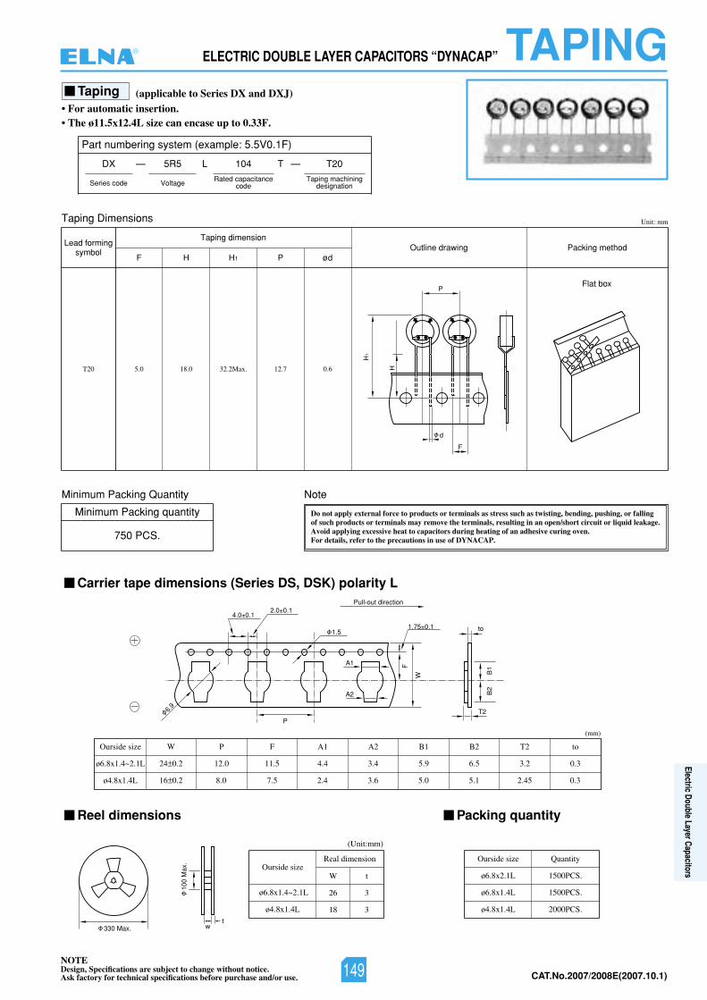
NOTEDesign, Specifications are subject to change without notice.Ask factory for technical specifications before purchase and/or use. CAT.No.2007/2008E(2007.10.1)
ELECTRIC DOUBLE LAYER CAPACITORS “DYNACAP” TAPING
A1
A2
1.5
2.0 0.14.0 0.1
6.9
P
Pull-out direction
1.75 0.1
F
W B1
B2
T2
to
100
Max
.
wt
330 Max.
F
d
PFlat box
H1
H
Taping
Carrier tape dimensions (Series DS, DSK) polarity L
Reel dimensions Packing quantity
• For automatic insertion.• The ø11.5x12.4L size can encase up to 0.33F.
(applicable to Series DX and DXJ)
Part numbering system (example: 5.5V0.1F)
DX — L T
Series code
5R5 104
Voltage
T20—
Taping machiningdesignation
Rated capacitancecode
Taping Dimensions Unit: mm
etoNytitnauQgnikcaPmuminiM
Minimum Packing quantity
750 PCS.
T20 5.0 18.0 32.2Max. 12.7 0.6
W P F A1 A2 B1 B2 T2 toOurside size
ø6.8x1.4~2.1L
ø4.8x1.4L
24 0.2 12.0 11.5 4.4 3.4 5.9 6.5 3.2 0.3
16 0.2 8.0 7.5 2.4 3.6 5.0 5.1 2.45 0.3
Lead formingsymbol
Taping dimension
F H H1 P øddohtemgnikcaPgniwardeniltuO
(mm)
Do not apply external force to products or terminals as stress such as twisting, bending, pushing, or fallingof such products or terminals may remove the terminals, resulting in an open/short circuit or liquid leakage.Avoid applying excessive heat to capacitors during heating of an adhesive curing oven.For details, refer to the precautions in use of DYNACAP.
Ourside sizeReal dimension
(Unit:mm)
W t
26 3
18 3
ø6.8x1.4~2.1L
ø4.8x1.4L
Ourside size Quantity
ø6.8x2.1L 1500PCS.
ø6.8x1.4L 1500PCS.
ø4.8x1.4L 2000PCS.
®
149
Electric Double Layer Capacitors
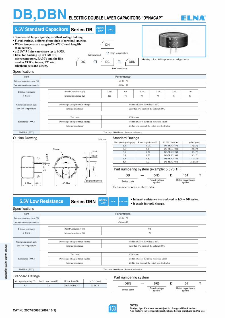
NOTEDesign, Specifications are subject to change without notice.Ask factory for technical specifications before purchase and/or use.CAT.No.2007/2008E(2007.10.1)
ELECTRIC DOUBLE LAYER CAPACITORS “DYNACAP”DB,DBN
Marking color : White print on an indigo sleeve
5.5V Standard Capacitors• Small-sized, large capacity, excellent voltage holding.• For all ratings, uniform 5mm pitch of terminal spacing.• Wider temperature range(–25~+70˚C) and long life
than battery.• ø13.5x7.5 e size can encase up to 0.33F.• Ideal for backing up of CMOS’s,
microcomputers, RAM’s and the like used in VCR’s, tuners, TV sets, telephone sets and others.
5.5V Low Resistance • Internal resistance was reduced to 1/3 to DB series.• It excels in rapid charge.
DX
sgnitaRdradnatSgniwarDeniltuO Unit: mm
6.0 1L Max D Max
5.0
0.3
0.5
0.1
Sleeve
Sn plated teminal
6.0
1
1.2 0.1
0.8 0.1
SpecificationsItem Performance
Category temperature range (˚C)
Tolerance at rated capacitance (%)
Internal resistance
at 1 kHz
Characteristics at high
and low temperature
Endurance (70˚C)
Shelf life (70˚ :emittseT)C 1000 hours ; Same as endurance.
25 to 70
20 to 80
Rated Capacitance (F) 0.047 0.1 0.22 0.33 0.47 1.0
120 75 75 75 30 30Internal resistance ( )
Percentage of capacitance change
Internal resistance
Within 30% of the value at 20˚C
Less than five times of the value at 20˚C
Test time
Percentage of capacitance change
Internal resistance
1000 hours
Within 30% of the initial measured value
Within four times of the initial specified value
SpecificationsItem Performance
Category temperature range (˚C)
Tolerance at rated capacitance (%)
Internal resistance
at 1 kHz
Characteristics at high
and low temperature
Endurance (70˚C)
Shelf life (70˚ :emittseT)C 1000 hours ; Same as endurance.
25 to 70
20 to 80
1.0)F(ecnaticapaCdetaR
25Internal resistance ( )
Percentage of capacitance change
Internal resistance
Within 30% of the value at 20˚C
Less than five times of the value at 20˚C
Test time
Percentage of capacitance change
Internal resistance
1000 hours
Within 30% of the initial measured value
Within four times of the initial specified value
Max. operating voltage(V) Rated capacitance(F) ø DxL(mm)ELNA Parts No.
5.5
5.5
5.5
5.5
5.5
5.5
DB-5R5D473T
DB-5R5D104T
DB-5R5D224T
DB-5R5D334T
DB-5R5D474T
DB-5R5D105T
13.5x7.5
13.5x7.5
13.5x7.5
13.5x7.5
21.5x8.0
21.5x8.0
0.047
0.1
0.22
0.33
0.47
1.0
DH
DB
High temperatureMiniaturized
DBN
Low resistance
Standard RatingsMax. operating voltage(V) Rated capacitance(F) ø DxL(mm)ELNA Parts No.
5.7x5.31T401D5R5-NBD5.5 0.1
Part numbering system (example: 5.5V0.1F)
DB —
Series code
5R5 104
Rated voltagesymbol
Rated capacitancesymbol
D T
Part numbering system
DBN —
Series code
5R5 104
Rated voltagesymbol
Rated capacitancesymbol
D T
Series DB
Series DBN
70˚CGREENCAP
70˚CGREENCAP
Low ESR
Part number is refer to above table.
®
150
Electric Double Layer Capacitors
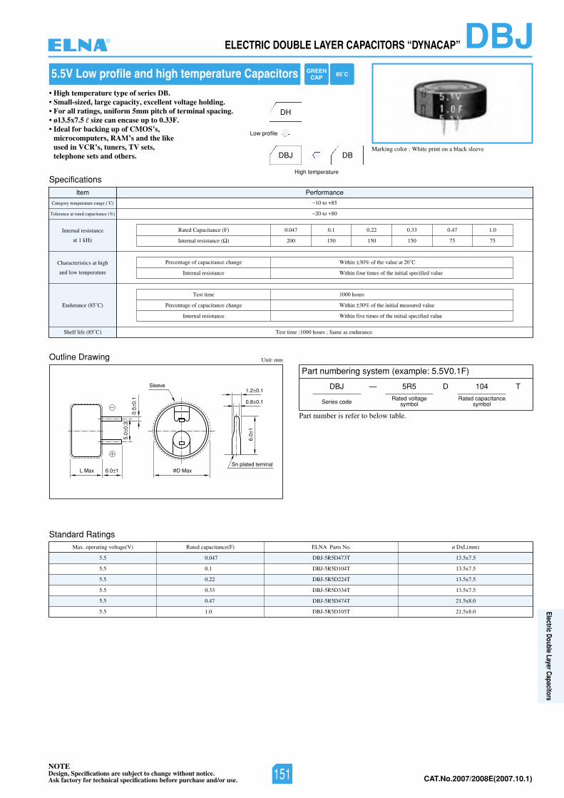
NOTEDesign, Specifications are subject to change without notice.Ask factory for technical specifications before purchase and/or use. CAT.No.2007/2008E(2007.10.1)
DBJELECTRIC DOUBLE LAYER CAPACITORS “DYNACAP”
Marking color : White print on a black sleeve
5.5V Low profile and high temperature Capacitors• High temperature type of series DB.• Small-sized, large capacity, excellent voltage holding.• For all ratings, uniform 5mm pitch of terminal spacing.• ø13.5x7.5 e size can encase up to 0.33F.• Ideal for backing up of CMOS’s,
microcomputers, RAM’s and the like used in VCR’s, tuners, TV sets, telephone sets and others.
Outline Drawing Unit: mm
6.0 1L Max D Max
5.0
0.3
0.5
0.1
Sleeve
Sn plated teminal
6.0
1
1.2 0.1
0.8 0.1
Specifications
Item Performance
Category temperature range (˚C)
Tolerance at rated capacitance (%)
Internal resistance
at 1 kHz
Characteristics at high
and low temperature
Endurance (85˚C)
Shelf life (85˚ :emittseT)C 1000 hours ; Same as endurance.
10 to 85
20 to 80
Rated Capacitance (F) 0.047 0.1 0.22 0.33 0.47 1.0
200 150 150 150 75 75Internal resistance ( )
Percentage of capacitance change
Internal resistance
Within 30% of the value at 20˚C
Within four times of the initial specified value
Test time
Percentage of capacitance change
Internal resistance
1000 hours
Within 30% of the initial measured value
Within five times of the initial specified value
DH
DBJ
Low profile
DB
High temperature
Part numbering system (example: 5.5V0.1F)
DBJ —
Series code
5R5 104
Rated voltagesymbol
Rated capacitancesymbol
D T
Standard RatingsMax. operating voltage(V) Rated capacitance(F) ø DxL(mm)ELNA Parts No.
5.5
5.5
5.5
5.5
5.5
5.5
DBJ-5R5D473T
DBJ-5R5D104T
DBJ-5R5D224T
DBJ-5R5D334T
DBJ-5R5D474T
DBJ-5R5D105T
13.5x7.5
13.5x7.5
13.5x7.5
13.5x7.5
21.5x8.0
21.5x8.0
0.047
0.1
0.22
0.33
0.47
1.0
Part number is refer to below table.
GREENCAP 85˚C
®
151
Electric Double Layer Capacitors
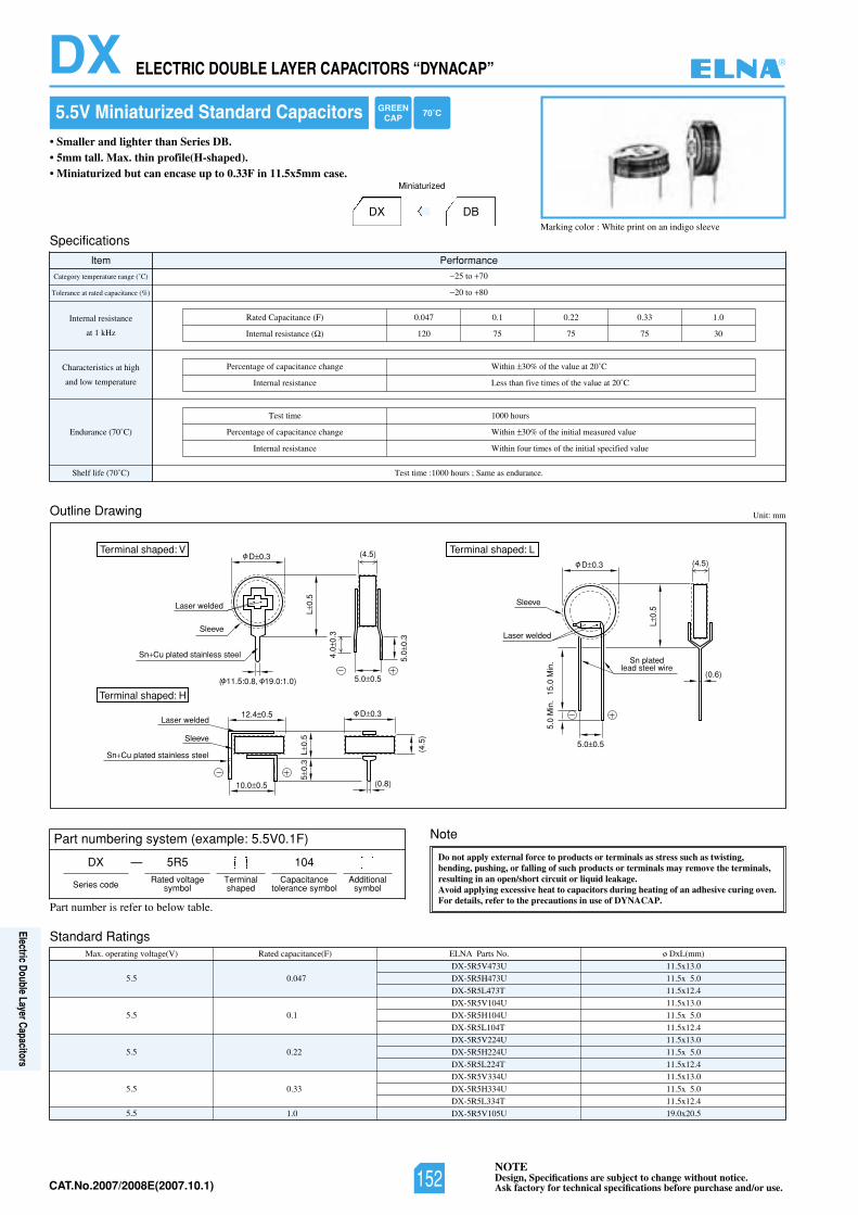
NOTEDesign, Specifications are subject to change without notice.Ask factory for technical specifications before purchase and/or use.CAT.No.2007/2008E(2007.10.1)
ELECTRIC DOUBLE LAYER CAPACITORS “DYNACAP”DX
Marking color : White print on an indigo sleeve
5.5V Miniaturized Standard Capacitors• Smaller and lighter than Series DB.• 5mm tall. Max. thin profile(H-shaped).• Miniaturized but can encase up to 0.33F in 11.5x5mm case.
DX
Outline Drawing
Standard Ratings
Unit: mm
(4.5)
(0.6)
5.0 0.5
15.0
Min
.5.
0 M
in.
L0.
5
D 0.3
Laser welded
Sn platedlead steel wire
Sleeve
Terminal shaped: LD 0.3
Terminal shaped: V
Terminal shaped: H
(4.5)
D 0.3
4.0
0.3
5.0
0.3
5.0 0.5
L0.
55
0.3
L0.
5
(4.5
)
12.4 0.5
10.0 0.5 (0.8)
( 11.5:0.8, 19.0:1.0)
Laser welded
Laser welded
Sleeve
Sleeve
Sn Cu plated stainless steel
Sn Cu plated stainless steel
Specifications
Item Performance
Category temperature range (˚C)
Tolerance at rated capacitance (%)
Internal resistance
at 1 kHz
Characteristics at high
and low temperature
Endurance (70˚C)
Shelf life (70˚ :emittseT)C 1000 hours ; Same as endurance.
25 to 70
20 to 80
Max. operating voltage(V) Rated capacitance(F) ø DxL(mm)ELNA Parts No.
5.5
5.5
5.5
5.5
5.5
DX-5R5V473U
DX-5R5H473U
DX-5R5L473T
DX-5R5V104U
DX-5R5H104U
DX-5R5L104T
DX-5R5V224U
DX-5R5H224U
DX-5R5L224T
DX-5R5V334U
DX-5R5H334U
DX-5R5L334T
DX-5R5V105U
11.5x13.0
11.5x 5.0
11.5x12.4
11.5x13.0
11.5x 5.0
11.5x12.4
11.5x13.0
11.5x 5.0
11.5x12.4
11.5x13.0
11.5x 5.0
11.5x12.4
19.0x20.5
0.047
0.1
0.22
0.33
1.0
DB
Miniaturized
0.133.022.01.0740.0)F(ecnaticapaCdetaR
120 75 75 75 30Internal resistance ( )
Percentage of capacitance change
Internal resistance
Within 30% of the value at 20˚C
Less than five times of the value at 20˚C
Test time
Percentage of capacitance change
Internal resistance
1000 hours
Within 30% of the initial measured value
Within four times of the initial specified value
Note
Do not apply external force to products or terminals as stress such as twisting,bending, pushing, or falling of such products or terminals may remove the terminals,resulting in an open/short circuit or liquid leakage.Avoid applying excessive heat to capacitors during heating of an adhesive curing oven.For details, refer to the precautions in use of DYNACAP.
Part numbering system (example: 5.5V0.1F)
DX —
Series code
5R5 104Rated voltage
symbolTerminalshaped
Capacitancetolerance symbol
Additionalsymbol
Part number is refer to below table.
GREENCAP 70˚C
®
152
Electric Double Layer Capacitors
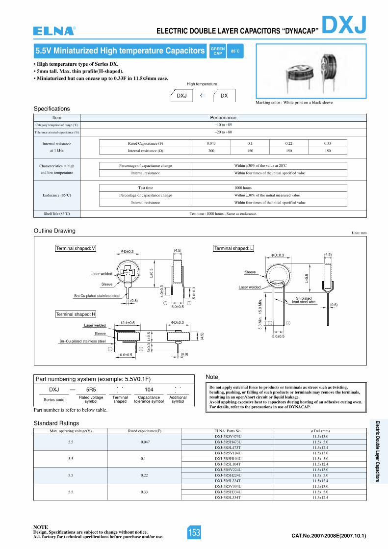
NOTEDesign, Specifications are subject to change without notice.Ask factory for technical specifications before purchase and/or use. CAT.No.2007/2008E(2007.10.1)
Note
Do not apply external force to products or terminals as stress such as twisting,bending, pushing, or falling of such products or terminals may remove the terminals,resulting in an open/short circuit or liquid leakage.Avoid applying excessive heat to capacitors during heating of an adhesive curing oven.For details, refer to the precautions in use of DYNACAP.
DXJELECTRIC DOUBLE LAYER CAPACITORS “DYNACAP”
Marking color : White print on a black sleeve
5.5V Miniaturized High temperature Capacitors• High temperature type of Series DX.• 5mm tall. Max. thin profile(H-shaped).• Miniaturized but can encase up to 0.33F in 11.5x5mm case.
DXJ
Outline Drawing
Standard Ratings
Unit: mm
(4.5)
(0.6)
5.0 0.5
15.0
Min
.5.
0 M
in.
L0.
5
D 0.3
Laser welded
Sn platedlead steel wire
Sleeve
Terminal shaped: LD 0.3
Terminal shaped: V
Terminal shaped: H
(4.5)
D 0.3
4.0
0.3
5.0
0.3
5.0 0.5
L0.
55
0.3
L0.
5
(4.5
)
12.4 0.5
10.0 0.5 (0.8)
(0.8)
Laser welded
Laser welded
Sleeve
Sleeve
Sn Cu plated stainless steel
Sn Cu plated stainless steel
Specifications
Item Performance
Category temperature range (˚C)
Tolerance at rated capacitance (%)
Internal resistance
at 1 kHz
Characteristics at high
and low temperature
Endurance (85˚C)
:emittseT)C˚58(efilflehS 1000 hours ; Same as endurance.
10 to 85
20 to 80
33.022.01.0740.0)F(ecnaticapaCdetaR
200 150 150 150Internal resistance ( )
Percentage of capacitance change
Internal resistance
Within 30% of the value at 20˚C
Within four times of the initial specified value
Test time
Percentage of capacitance change
Internal resistance
1000 hours
Within 30% of the initial measured value
Within four times of the initial specified value
Max. operating voltage(V) Rated capacitance(F) ø DxL(mm)ELNA Parts No.
5.5
5.5
5.5
5.5
DXJ-5R5V473U
DXJ-5R5H473U
DXJ-5R5L473T
DXJ-5R5V104U
DXJ-5R5H104U
DXJ-5R5L104T
DXJ-5R5V224U
DXJ-5R5H224U
DXJ-5R5L224T
DXJ-5R5V334U
DXJ-5R5H334U
DXJ-5R5L334T
11.5x13.0
11.5x 5.0
11.5x12.4
11.5x13.0
11.5x 5.0
11.5x12.4
11.5x13.0
11.5x 5.0
11.5x12.4
11.5x13.0
11.5x 5.0
11.5x12.4
0.047
0.1
0.22
0.33
DX
High temperature
Part numbering system (example: 5.5V0.1F)
DXJ —
Series code
5R5 104Rated voltage
symbolTerminalshaped
Capacitancetolerance symbol
Additionalsymbol
Part number is refer to below table.
GREENCAP 85˚C
®
153
Electric Double Layer Capacitors
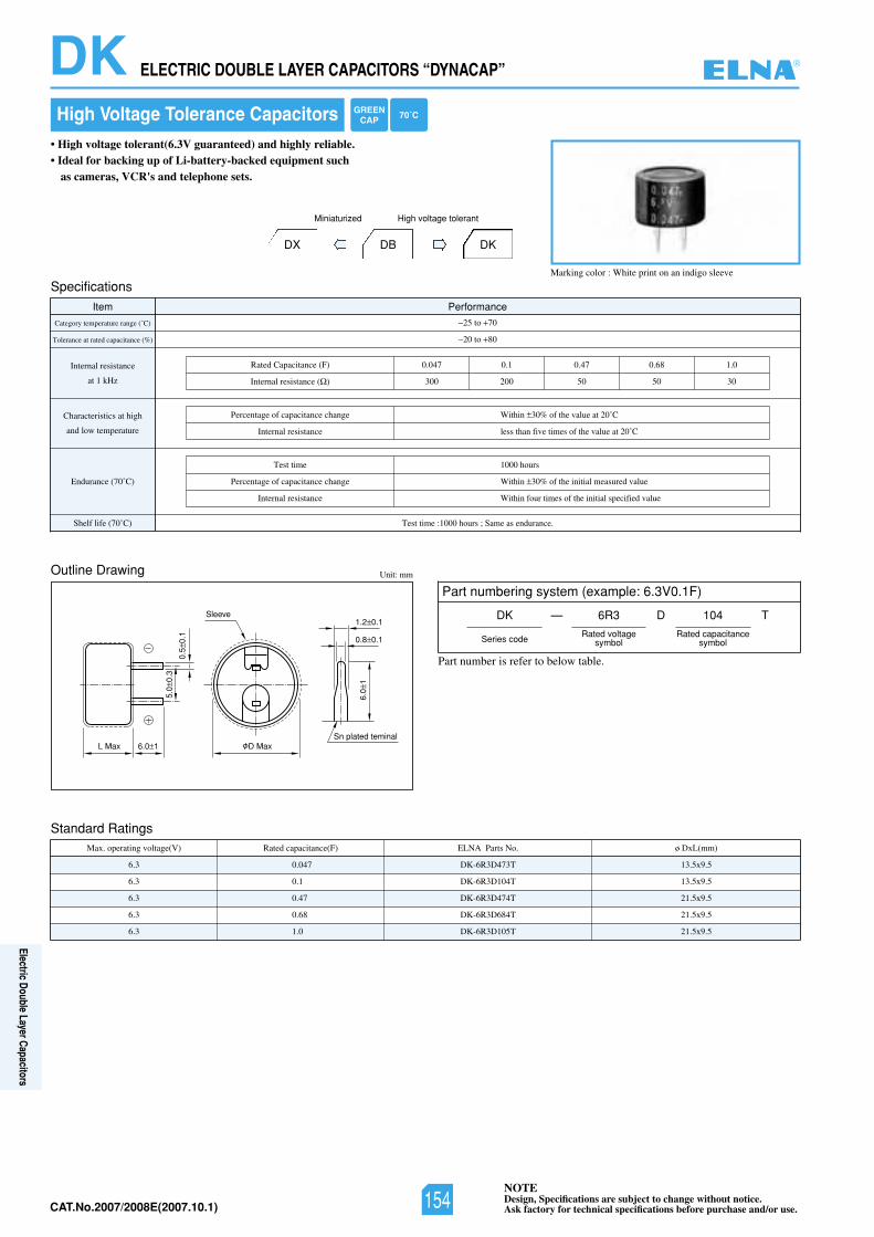
NOTEDesign, Specifications are subject to change without notice.Ask factory for technical specifications before purchase and/or use.CAT.No.2007/2008E(2007.10.1)
ELECTRIC DOUBLE LAYER CAPACITORS “DYNACAP”DK
Marking color : White print on an indigo sleeve
High Voltage Tolerance Capacitors• High voltage tolerant(6.3V guaranteed) and highly reliable.• Ideal for backing up of Li-battery-backed equipment such
as cameras, VCR's and telephone sets.
DX
Specifications
Item Performance
Category temperature range (˚C)
Tolerance at rated capacitance (%)
Internal resistance
at 1 kHz
Characteristics at high
and low temperature
Endurance (70˚C)
Shelf life (70˚ :emittseT)C 1000 hours ; Same as endurance.
25 to 70
20 to 80
DB
Miniaturized
DK
High voltage tolerant
0.186.074.01.0740.0)F(ecnaticapaCdetaR
300 200 50 50 30Internal resistance ( )
Percentage of capacitance change
Internal resistance
Within 30% of the value at 20˚C
less than five times of the value at 20˚C
Test time
Percentage of capacitance change
Internal resistance
1000 hours
Within 30% of the initial measured value
Within four times of the initial specified value
Outline Drawing
Standard Ratings
Unit: mm
6.0 1L Max D Max
5.0
0.3
0.5
0.1
Sleeve
Sn plated teminal
6.0
1
1.2 0.1
0.8 0.1
Max. operating voltage(V) Rated capacitance(F) ø DxL(mm)ELNA Parts No.
6.3
6.3
6.3
6.3
6.3
DK-6R3D473T
DK-6R3D104T
DK-6R3D474T
DK-6R3D684T
DK-6R3D105T
13.5x9.5
13.5x9.5
21.5x9.5
21.5x9.5
21.5x9.5
0.047
0.1
0.47
0.68
1.0
Part numbering system (example: 6.3V0.1F)
DK —
Series code
6R3 104
Rated voltagesymbol
Rated capacitancesymbol
D T
GREENCAP 70˚C
Part number is refer to below table.
®
154
Electric Double Layer Capacitors
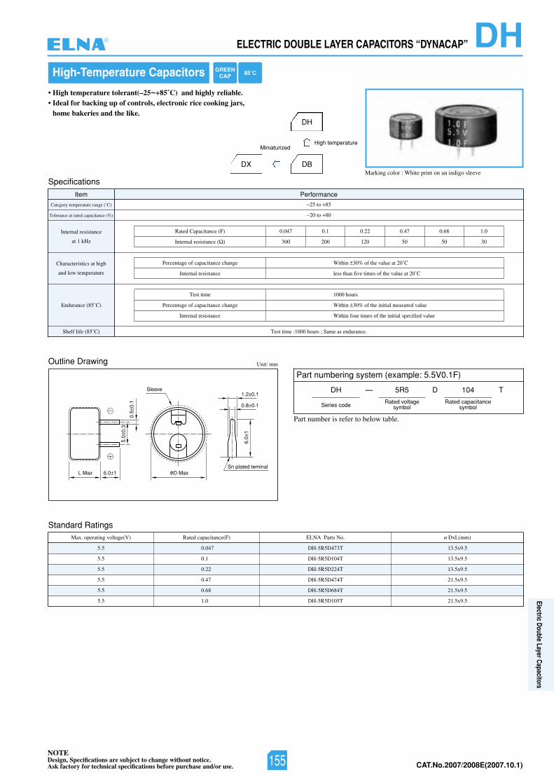
NOTEDesign, Specifications are subject to change without notice.Ask factory for technical specifications before purchase and/or use. CAT.No.2007/2008E(2007.10.1)
ELECTRIC DOUBLE LAYER CAPACITORS “DYNACAP” DH
Marking color : White print on an indigo sleeve
High-Temperature Capacitors
• High temperature tolerant(–25~+85˚C) and highly reliable.• Ideal for backing up of controls, electronic rice cooking jars,
home bakeries and the like.
DX
Outline Drawing
Standard Ratings
Unit: mm
6.0 1L Max D Max
5.0
0.3
0.5
0.1
Sleeve
Sn plated teminal
6.0
1
1.2 0.1
0.8 0.1
Specifications
Item Performance
Category temperature range (˚C)
Tolerance at rated capacitance (%)
Internal resistance
at 1 kHz
Characteristics at high
and low temperature
Endurance (85˚C)
Shelf life (85˚ :emittseT)C 1000 hours ; Same as endurance.
25 to 85
20 to 80
Rated Capacitance (F) 0.047 0.1 0.22 0.47 0.68 1.0
300 200 120 50 50 30Internal resistance ( )
Percentage of capacitance change
Internal resistance
Within 30% of the value at 20˚C
less than five times of the value at 20˚C
Test time
Percentage of capacitance change
Internal resistance
1000 hours
Within 30% of the initial measured value
Within four times of the initial specified value
Max. operating voltage(V) Rated capacitance(F) ø DxL(mm)ELNA Parts No.
5.5
5.5
5.5
5.5
5.5
5.5
DH-5R5D473T
DH-5R5D104T
DH-5R5D224T
DH-5R5D474T
DH-5R5D684T
DH-5R5D105T
13.5x9.5
13.5x9.5
13.5x9.5
21.5x9.5
21.5x9.5
21.5x9.5
0.047
0.1
0.22
0.47
0.68
1.0
DH
DB
High temperatureMiniaturized
Part numbering system (example: 5.5V0.1F)
DH —
Series code
5R5 104
Rated voltagesymbol
Rated capacitancesymbol
D T
GREENCAP 85˚C
Part number is refer to below table.
®
155
Electric Double Layer Capacitors
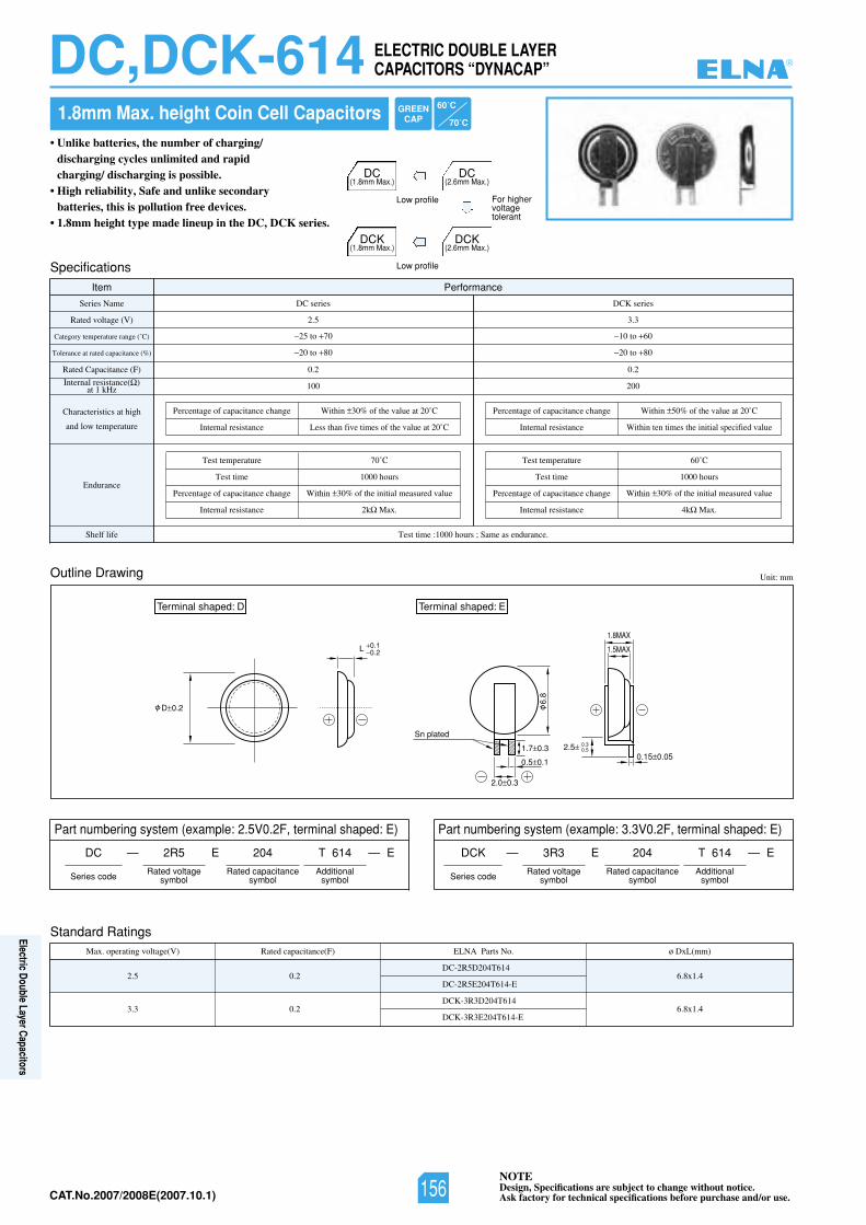
NOTEDesign, Specifications are subject to change without notice.Ask factory for technical specifications before purchase and/or use.CAT.No.2007/2008E(2007.10.1)
• Unlike batteries, the number of charging/discharging cycles unlimited and rapid charging/ discharging is possible.
• High reliability, Safe and unlike secondary batteries, this is pollution free devices.
• 1.8mm height type made lineup in the DC, DCK series.
ELECTRIC DOUBLE LAYERCAPACITORS “DYNACAP”DC,DCK-614
Standard RatingsMax. operating voltage(V) Rated capacitance(F) ø DxL(mm)ELNA Parts No.
2.5
3.3
DC-2R5D204T614
DC-2R5E204T614-E
DCK-3R3D204T614
DCK-3R3E204T614-E
6.8x1.4
6.8x1.4
0.2
0.2
Outline Drawing Unit: mm
D 0.2
L 0.10.2
0.15 0.05
1.8MAX
1.5MAX
2.0 0.3
0.5 0.1
1.7 0.3 2.5 0.30.5
6.8
Sn plated
Terminal shaped: ETerminal shaped: D
Specifications
Item Performance
Series Name
Rated voltage (V)
Category temperature range (˚C)
Tolerance at rated capacitance (%)
Rated Capacitance (F)
Internal resistance( )at 1 kHz
Characteristics at high
and low temperature
Endurance
Shelf life Test time :1000 hours ; Same as endurance.
25 to 70 10 to 60
DC series DCK series
2.5 3.3
20 to 80 20 to 80
0.2
100
0.2
200
Percentage of capacitance change
Internal resistance
Within 30% of the value at 20˚C
Less than five times of the value at 20˚C
Percentage of capacitance change
Internal resistance
Within 50% of the value at 20˚C
Within ten times the initial specified value
Test temperature
Test time
Percentage of capacitance change
Internal resistance
70˚C
1000 hours
Within 30% of the initial measured value
2k Max.
Test temperature
Test time
Percentage of capacitance change
Internal resistance
60˚C
1000 hours
Within 30% of the initial measured value
4k Max.
For higher voltagetolerant
Part numbering system (example: 2.5V0.2F, terminal shaped: E)
DC ——
Series code
2R5 204 T 614
Rated voltagesymbol
Rated capacitancesymbol
EE
Part numbering system (example: 3.3V0.2F, terminal shaped: E)
1.8mm Max. height Coin Cell Capacitors
DCK(1.8mm Max.)
DCK(2.6mm Max.)
Low profile
Additionalsymbol
DCK ——
Series code
3R3 204 T 614
Rated voltagesymbol
Rated capacitancesymbol
EE
Additionalsymbol
DC(1.8mm Max.)
DC(2.6mm Max.)
Low profile
60˚C
70˚C
GREENCAP
®
156
Electric Double Layer Capacitors
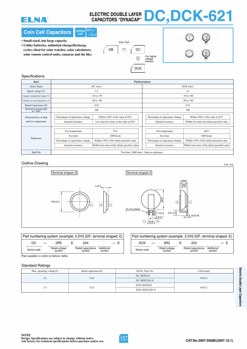
NOTEDesign, Specifications are subject to change without notice.Ask factory for technical specifications before purchase and/or use. CAT.No.2007/2008E(2007.10.1)
Standard RatingsMax. operating voltage(V) Rated capacitance(F) ø DxL(mm)ELNA Parts No.
2.5
3.3
DC-2R5D224
DC-2R5E224U-E
DCK-3R3D224
DCK-3R3E224U-E
6.8x2.1
6.8x2.1
0.22
0.22
Coin Cell Capacitors• Small-sized, but large capacity.• Unlike batteries, unlimited charge/discharge
cycles; ideal for solar watches, solar calculators, solar remote control units, camaras and the like.
Outline Drawing Unit: mm
D 0.2
L 0.2
0.15 0.05
2.6MAX
2.3MAX
2.0 0.3
0.5 0.1
1.7 0.3 2.5 0.30.5
6.8
Sn Cu plated
Terminal shaped: ETerminal shaped: D
Specifications
Item Performance
Series Name
Rated voltage (V)
Category temperature range (˚C)
Tolerance at rated capacitance (%)
Rated Capacitance (F)
Internal resistance( )at 1 kHz
Characteristics at high
and low temperature
Endurance
Shelf life Test time :1000 hours ; Same as endurance.
25 to 70 10 to 60
DC series DCK series
2.5 3.3
20 to 80 20 to 80
0.22
100
0.22
200
Percentage of capacitance change
Internal resistance
Within 30% of the value at 20˚C
Less than five times of the value at 20˚C
Percentage of capacitance change
Internal resistance
Within 50% of the value at 20˚C
Within five times the initial specified value
Test temperature
Test time
Percentage of capacitance change
Internal resistance
70˚C
1000 hours
Within 30% of the initial measured value
Within four times of the initial specified value
Test temperature
Test time
Percentage of capacitance change
Internal resistance
60˚C
1000 hours
Within 30% of the initial measured value
Within four times of the initial specified value
DB DC
DCK
For higher voltagetolerant
Coin Cell
Part numbering system (example: 2.5V0.22F, terminal shaped: E)
DC ——
Series code
DCK
Series code
2R5 224
Rated voltagesymbol
Rated capacitancesymbol
EE
Part numbering system (example: 3.3V0.22F, terminal shaped: E)
—— 3R3 224
Rated voltagesymbol
Rated capacitancesymbol
EE
Additionalsymbol
Additionalsymbol
Part number is refer to below table.
GREENCAP
60˚C
70˚C
ELECTRIC DOUBLE LAYERCAPACITORS “DYNACAP” DC,DCK-621®
157
Electric Double Layer Capacitors
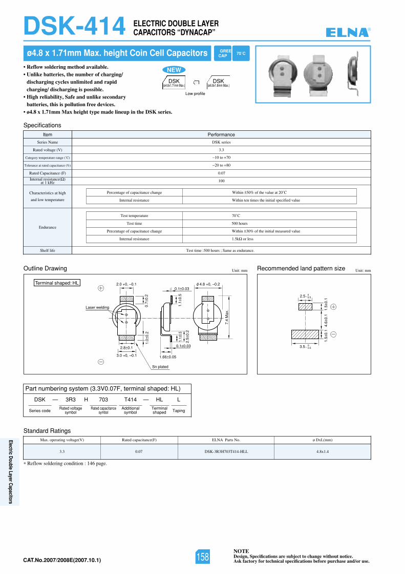
NOTEDesign, Specifications are subject to change without notice.Ask factory for technical specifications before purchase and/or use.CAT.No.2007/2008E(2007.10.1)
Standard RatingsMax. operating voltage(V) Rated capacitance(F) ø DxL(mm)ELNA Parts No.
3.3 DSK-3R3H703T414-HLL 4.8x1.40.07
• Reflow soldering method available.• Unlike batteries, the number of charging/
discharging cycles unlimited and rapid charging/ discharging is possible.
• High reliability, Safe and unlike secondary batteries, this is pollution free devices.
• ø4.8 x 1.71mm Max height type made lineup in the DSK series.
ezisnrettapdnaldednemmoceRgniwarDeniltuO Unit: mmUnit: mm
Terminal shaped: HL
Specifications
Item Performance
Series Name
Category temperature range (˚C)
Tolerance at rated capacitance (%)
Rated Capacitance (F)
Internal resistance( )at 1 kHz
Characteristics at high
and low temperature
Endurance
Shelf life Test time :500 hours ; Same as endurance.
10 to 70
)V(egatlovdetaR
DSK series
3.3
20 to 80
0.07
100
Percentage of capacitance change
Internal resistance
Within 50% of the value at 20˚C
Within ten times the initial specified value
1.5k or less
Test temperature
Test time
Percentage of capacitance change
Internal resistance
70˚C
500 hours
Within 30% of the initial measured value
Reflow soldering condition : 146 page.
ELECTRIC DOUBLE LAYERCAPACITORS “DYNACAP”DSK-414
DSK ——
Series code
3R3 703 HL
Rated voltagesymbol
Rated capacitancesymbol
H
Terminalshaped
L
Taping
T414
Additionalsymbol
Part numbering system (3.3V0.07F, terminal shaped: HL)
ø4.8 x 1.71mm Max. height Coin Cell Capacitors GREENCAP
DSK(ø4.8x1.71mm Max.)
DSK(ø6.8x1.8mm Max.)
Low profile
70˚C
NEW
2.0 +0, –0.1
3.0 +0, –0.1
Laser welding 0.7±
0.2
1.1 ±
0.5
2.5 ±
0.2
1.1 ±
0.5
1.0±
0.2
2.8±0.1
0.1±0.03
0.1±0.03
1.66±0.05
φ4.8 +0, –0.2
7.4
Max
.
Sn plated
2.5 _ 00.5
3.5 _ 00.5
1.5±
0.1
4.6±
0.1
1.5±
0.1
®
158
Electric Double Layer Capacitors
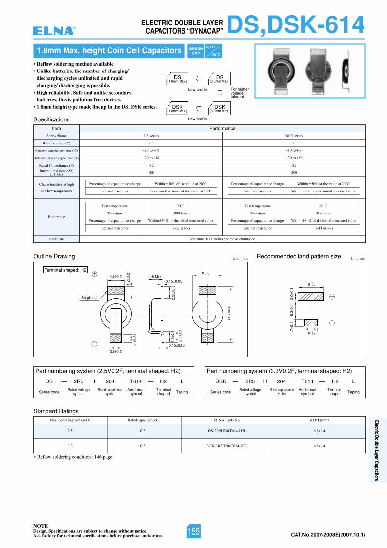
NOTEDesign, Specifications are subject to change without notice.Ask factory for technical specifications before purchase and/or use. CAT.No.2007/2008E(2007.10.1)
Standard RatingsMax. operating voltage(V) Rated capacitance(F) ø DxL(mm)ELNA Parts No.
2.5
3.3
DS-2R5H204T614-H2L
DSK-3R3H204T614-H2L
6.8x1.4
6.8x1.4
0.2
0.2
• Reflow soldering method available.• Unlike batteries, the number of charging/
discharging cycles unlimited and rapid charging/ discharging is possible.
• High reliability, Safe and unlike secondary batteries, this is pollution free devices.
• 1.8mm height type made lineup in the DS, DSK series.
ezisnrettapdnaldednemmoceRgniwarDeniltuO Unit: mmUnit: mm
0.15 0.05
1.2
0.2
2.25
0.3
2.5
0.3
1.3
0.3
0.9
0.2
11.7
Max
.
3.0 0.2
4.0 0.2 1.8 Max.0.15 0.05
6.8Terminal shaped: H2
Sn plated
5 00.5
4 00.5
2.0
0.1
8.3
0.1
1.7
0.1
Specifications
Item Performance
Series Name
Category temperature range (˚C)
Tolerance at rated capacitance (%)
Rated Capacitance (F)
Internal resistance( )at 1 kHz
Characteristics at high
and low temperature
Endurance
Shelf life Test time :1000 hours ; Same as endurance.
25 to 70 10 to 60
DS series
5.2)V(egatlovdetaR
DSK series
3.3
20 to 80 20 to 80
0.2
100
0.2
200
Percentage of capacitance change
Internal resistance
Within 30% of the value at 20˚C
Less than five times of the value at 20˚C
Percentage of capacitance change
Internal resistance
Within 50% of the value at 20˚C
Within ten times the initial specified value
Test temperature
Test time
Percentage of capacitance change
Internal resistance
70˚C
1000 hours
Within 30% of the initial measured value
2k or less 4k or less
Test temperature
Test time
Percentage of capacitance change
Internal resistance
60˚C
1000 hours
Within 30% of the initial measured value
Reflow soldering condition : 146 page.
Part numbering system (2.5V0.2F, terminal shaped: H2)
DS ——
Series code
2R5 204 H2
Rated voltagesymbol
Rated capacitancesymbol
H
Terminalshaped
L
Taping
T614
Additionalsymbol
DSK ——
Series code
3R3 204 H2
Rated voltagesymbol
Rated capacitancesymbol
H
Terminalshaped
L
Taping
T614
Additionalsymbol
Part numbering system (3.3V0.2F, terminal shaped: H2)
1.8mm Max. height Coin Cell Capacitors 60˚C
70˚C
GREENCAP
For higher voltagetolerant
DSK(1.8mm Max.)
DSK(3.0mm Max.)
Low profile
DS(1.8mm Max.)
DS(3.0mm Max.)
Low profile
DS,DSK-614ELECTRIC DOUBLE LAYERCAPACITORS “DYNACAP”®
159
Electric Double Layer Capacitors
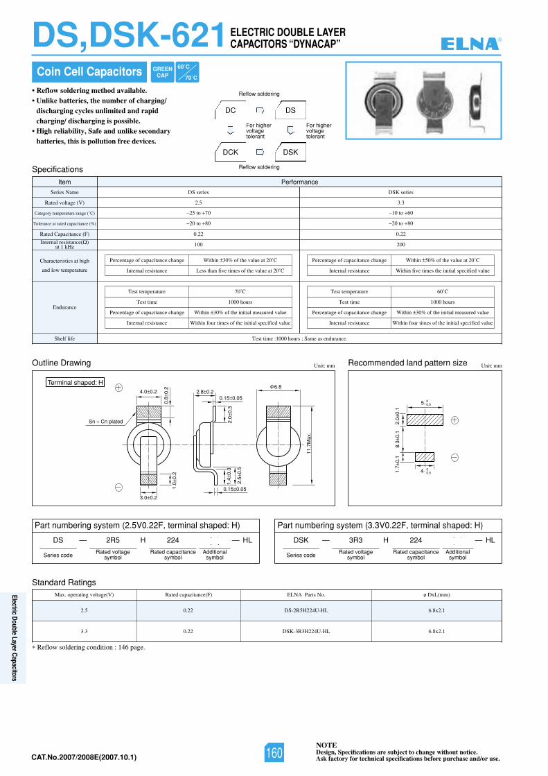
NOTEDesign, Specifications are subject to change without notice.Ask factory for technical specifications before purchase and/or use.CAT.No.2007/2008E(2007.10.1)
Standard RatingsMax. operating voltage(V) Rated capacitance(F) ø DxL(mm)ELNA Parts No.
2.5
3.3
DS-2R5H224U-HL
DSK-3R3H224U-HL
6.8x2.1
6.8x2.1
0.22
0.22
Coin Cell Capacitors• Reflow soldering method available.• Unlike batteries, the number of charging/
discharging cycles unlimited and rapid charging/ discharging is possible.
• High reliability, Safe and unlike secondary batteries, this is pollution free devices.
ezisnrettapdnaldednemmoceRgniwarDeniltuO Unit: mmUnit: mm
0.15 0.05
0.8
0.2
2.0
0.3
2.5
0.5
1.4
0.3
1.0
0.2
11.7
Max
.
3.0 0.2
4.0 0.2 2.8 0.20.15 0.05
6.8Terminal shaped: H
Sn Cn plated
5 00.5
4 00.5
2.0
0.1
8.3
0.1
1.7
0.1
Specifications
Item Performance
Series Name
Category temperature range (˚C)
Tolerance at rated capacitance (%)
Rated Capacitance (F)
Internal resistance( )at 1 kHz
Characteristics at high
and low temperature
Endurance
Shelf life Test time :1000 hours ; Same as endurance.
25 to 70 10 to 60
DS series
5.2)V(egatlovdetaR
DSK series
3.3
20 to 80 20 to 80
0.22
100
0.22
200
Percentage of capacitance change
Internal resistance
Within 30% of the value at 20˚C
Less than five times of the value at 20˚C
Percentage of capacitance change
Internal resistance
Within 50% of the value at 20˚C
Within five times the initial specified value
Test temperature
Test time
Percentage of capacitance change
Internal resistance
70˚C
1000 hours
Within 30% of the initial measured value
Within four times of the initial specified value
Test temperature
Test time
Percentage of capacitance change
Internal resistance
60˚C
1000 hours
Within 30% of the initial measured value
Within four times of the initial specified value
DC
DCK
DS
DSK
For higher voltagetolerant
For higher voltagetolerant
Reflow soldering
Reflow soldering
Reflow soldering condition : 146 page.
Part numbering system (2.5V0.22F, terminal shaped: H)
DS ——
Series code
2R5 224
Rated voltagesymbol
Rated capacitancesymbol
LHH
Additionalsymbol
Part numbering system (3.3V0.22F, terminal shaped: H)
DSK ——
Series code
3R3 224
Rated voltagesymbol
Rated capacitancesymbol
LHH
Additionalsymbol
GREENCAP
60˚C
70˚C
DS,DSK-621ELECTRIC DOUBLE LAYERCAPACITORS “DYNACAP” ®
160
Electric Double Layer Capacitors
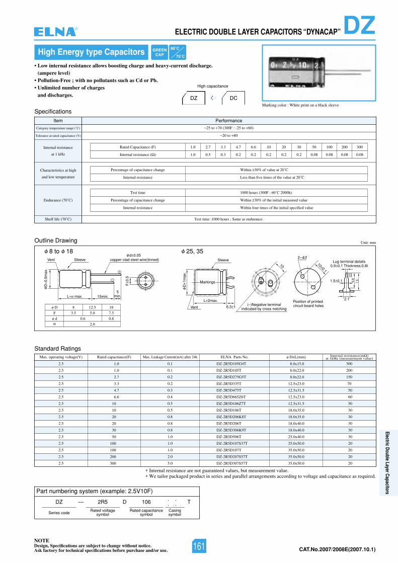
NOTEDesign, Specifications are subject to change without notice.Ask factory for technical specifications before purchase and/or use. CAT.No.2007/2008E(2007.10.1)
Marking color : White print on a black sleeve
High Energy type Capacitors• Low internal resistance allows boosting charge and heavy-current discharge.
(ampere level)• Pollution-Free ; with no pollutants such as Cd or Pb.• Unlimited number of charges
and discharges. DZ
Outline Drawing
Standard Ratings
Unit: mm
L 2max.
D1m
ax.
Sleeve
Vent
1.5 0.1
6.3 1
Lug terminal details0.9 0.1 Thickness:0.8t
Position of printedcircuit board holes(–)Negative terminal
indicated by cross notching
2.1
7.5 6.8
2.6
100.1
10
2– 2
Markings
L max.
ø D
F
ø d
8
3.5
0.6
12.5
5.0
2.0
18
7.5
0.8
15min.5
min.
Sleeve
D0.
5max
.
F0.
5
d 0.05copper clad steel wire(tinned)Vent
53,5281ot8
Specifications
Item Performance
Category temperature range (˚C)
Tolerance at rated capacitance (%)
Internal resistance
at 1 kHz
Characteristics at high
and low temperature
Endurance (70˚C)
Shelf life (70˚ :emittseT)C 1000 hours ; Same as endurance.
25 to 70 (300F : -25 to +60)
20 to 80
Rated Capacitance (F) 1.0 2.7 3.3 4.7 6.6 10 20 30 50 100 200 300
1.0 0.5 0.3 0.2 0.2 0.2 0.2 0.2 0.08 0.08 0.08 0.08Internal resistance ( )
Percentage of capacitance change
Internal resistance
Within 30% of value at 20˚C
Less than five times of the value at 20˚C
Test time
Percentage of capacitance change
Internal resistance
1000 hours (300F : 60˚C 2000h)
Within 30% of the initial measured value
Within four times of the initial specified value
Max. operating voltage(V) Rated capacitance(F) ø DxL(mm)ELNA Parts No.
2.5
2.5
2.5
2.5
2.5
2.5
2.5
2.5
2.5
2.5
2.5
2.5
2.5
2.5
2.5
2.5
DZ-2R5D105G4T
DZ-2R5D105T
DZ-2R5D275G5T
DZ-2R5D335T
DZ-2R5D475T
DZ-2R5D665Z6T
DZ-2R5D106Z7T
DZ-2R5D106T
DZ-2R5D206K8T
DZ-2R5D206T
DZ-2R5D306K9T
DZ-2R5D506T
DZ-2R5D107S37T
DZ-2R5D107T
DZ-2R5D207S57T
DZ-2R5D307S57T
8.0x15.0
8.0x22.0
8.0x22.0
12.5x23.0
12.5x31.5
12.5x23.0
12.5x31.5
18.0x35.0
18.0x35.0
18.0x40.0
18.0x40.0
25.0x40.0
25.0x50.0
35.0x50.0
35.0x50.0
35.0x50.0
1.0
1.0
2.7
3.3
4.7
6.6
10
10
20
20
30
50
100
100
200
300
Internal resistance(m )at 1kHz (measurement value)
300
200
150
70
50
60
50
30
30
30
30
30
20
20
20
20
Max. Leakage Current(mA) after 24h
0.1
0.1
0.2
0.2
0.3
0.4
0.5
0.5
0.8
0.8
0.8
1.0
1.0
1.0
2.0
5.0
DC
High capacitance
Internal resistance are not guaranteed values, but measurement value.We tailor packaged product in series and parallel arrangements according to voltage and capacitance as required.
Part numbering system (example: 2.5V10F)
DZ —
Series code
2R5 106
Rated voltagesymbol
Rated capacitancesymbol
TD
GREENCAP
60˚C
70˚C
Casingsymbol
DZELECTRIC DOUBLE LAYER CAPACITORS “DYNACAP”®
161
Electric Double Layer Capacitors
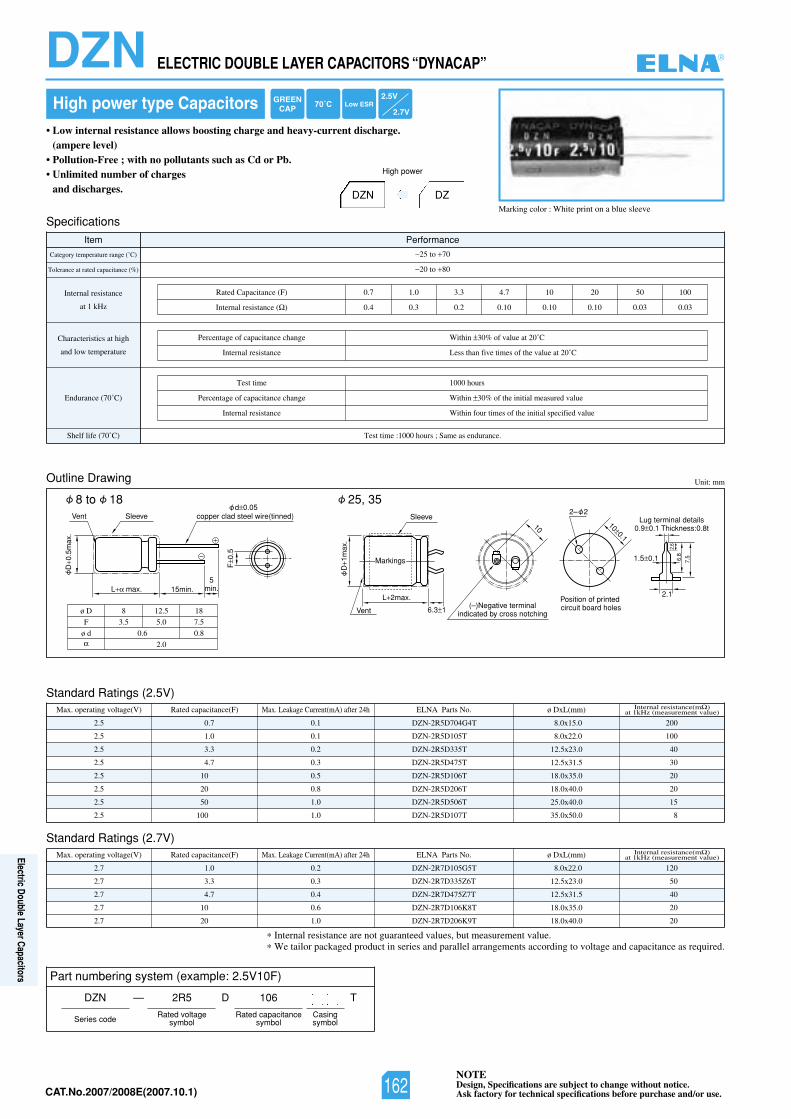
NOTEDesign, Specifications are subject to change without notice.Ask factory for technical specifications before purchase and/or use.CAT.No.2007/2008E(2007.10.1)
Marking color : White print on a blue sleeve
High power type Capacitors• Low internal resistance allows boosting charge and heavy-current discharge.
(ampere level)• Pollution-Free ; with no pollutants such as Cd or Pb.• Unlimited number of charges
and discharges. DZDZN
Outline Drawing Unit: mm
L 2max.
D1m
ax.
Sleeve
Vent
1.5 0.1
6.3 1
Lug terminal details0.9 0.1 Thickness:0.8t
Position of printedcircuit board holes(–)Negative terminal
indicated by cross notching
2.1
7.5 6.8
2.6
100.1
10
2– 2
Markings
L max.
ø D
F
ø d
8
3.5
0.6
12.5
5.0
2.0
18
7.5
0.8
15min.5
min.
Sleeve
D0.
5max
.
F0.
5
d 0.05copper clad steel wire(tinned)Vent
53,5281ot8
Specifications
Item Performance
Category temperature range (˚C)
Tolerance at rated capacitance (%)
Internal resistance
at 1 kHz
Characteristics at high
and low temperature
Endurance (70˚C)
Shelf life (70˚ :emittseT)C 1000 hours ; Same as endurance.
25 to 70
20 to 80
Rated Capacitance (F) 0.7 1.0 3.3 4.7 10 20 50 100
0.4 0.3 0.2 0.10 0.10 0.10 0.03 0.03Internal resistance ( )
Percentage of capacitance change
Internal resistance
Within 30% of value at 20˚C
Less than five times of the value at 20˚C
Test time
Percentage of capacitance change
Internal resistance
1000 hours
Within 30% of the initial measured value
Within four times of the initial specified value
High power
Internal resistance are not guaranteed values, but measurement value.We tailor packaged product in series and parallel arrangements according to voltage and capacitance as required.
GREENCAP 70˚C Low ESR
2.5V
2.7V
Part numbering system (example: 2.5V10F)
DZN —
Series code
2R5 106
Rated voltagesymbol
Rated capacitancesymbol
TD
Casingsymbol
Standard Ratings (2.5V)Max. operating voltage(V) Rated capacitance(F) ø DxL(mm)ELNA Parts No.
2.5
2.5
2.5
2.5
2.5
2.5
2.5
2.5
DZN-2R5D704G4T
DZN-2R5D105T
DZN-2R5D335T
DZN-2R5D475T
DZN-2R5D106T
DZN-2R5D206T
DZN-2R5D506T
DZN-2R5D107T
8.0x15.0
8.0x22.0
12.5x23.0
12.5x31.5
18.0x35.0
18.0x40.0
25.0x40.0
35.0x50.0
0.7
1.0
3.3
4.7
10
20
50
100
Internal resistance(m )at 1kHz (measurement value)
200
100
40
30
20
20
15
8
Max. Leakage Current(mA) after 24h
0.1
0.1
0.2
0.3
0.5
0.8
1.0
1.0
Standard Ratings (2.7V)Max. operating voltage(V) Rated capacitance(F) ø DxL(mm)ELNA Parts No.
2.7
2.7
2.7
2.7
2.7
DZN-2R7D105G5T
DZN-2R7D335Z6T
DZN-2R7D475Z7T
DZN-2R7D106K8T
DZN-2R7D206K9T
8.0x22.0
12.5x23.0
12.5x31.5
18.0x35.0
18.0x40.0
1.0
3.3
4.7
10
20
Internal resistance(m )at 1kHz (measurement value)
120
50
40
20
20
Max. Leakage Current(mA) after 24h
0.2
0.3
0.4
0.6
1.0
DZN ELECTRIC DOUBLE LAYER CAPACITORS “DYNACAP” ®
162
Electric Double Layer Capacitors
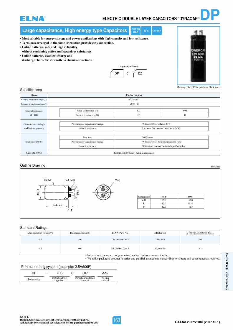
NOTEDesign, Specifications are subject to change without notice.Ask factory for technical specifications before purchase and/or use. CAT.No.2007/2008E(2007.10.1)
Specifications
Item Performance
Category temperature range (˚C)
Tolerance at rated capacitance (%)
Internal resistance
at 1 kHz
Characteristics at high
and low temperature
Endurance (60˚C)
Shelf life (60˚ :emittseT)C 2000 hours ; Same as endurance.
25 to 60
20 to 20
005)F(ecnaticapaCdetaR
12
600
10Internal resistance (m )
Percentage of capacitance change
Internal resistance
Within 30% of value at 20˚C
Less than five times of the value at 20˚C
Test time
Percentage of capacitance change
Internal resistance
2000 hours
Within 30% of the initial measured value
Within four times of the initial specified value
Internal resistance are not guaranteed values, but measurement value.We tailor packaged product in series and parallel arrangements according to voltage and capacitance as required.
Part numbering system (example: 2.5V600F)
DP —
Series code
2R5 607
Rated voltagesymbol
Rated capacitancesymbol
AA5
Casingsymbol
D
Standard RatingsMax. operating voltage(V)
2.5
Rated capacitance(F)
500
ELNA Parts No.
DP-2R5D507A85
ø DxL(mm)
35.0x85.0
Internal resistance(m )at 1kHz (measurement value)
4.0
2.30.501x0.535AA706D5R2-PD0065.2
Large capacitance, High energy type Capacitors• Most suitable for energy storage and power applications with high capacity and low resistance.• Terminals arranged in the same orientation provide easy connection.• Unlike batteries, safe and high reliability
without containing active and hazardous substances.• Unlike batteries, excellent charge and
discharge characteristics with no chemical reactions.
Outline Drawing Unit: mm
L 4max.
Bolt (M5)Sleeve
6 1
F1
D1
Vent
DZDP
Large capacitance
Marking color : White print on a black sleeve
ø D
L
F
Capacitance
35.0
85.0
12.7
35.0
105.0
12.7
500F 600F
GREENCAP 60˚C Low ESR
DPELECTRIC DOUBLE LAYER CAPACITORS “DYNACAP”®
163
Electric Double Layer Capacitors
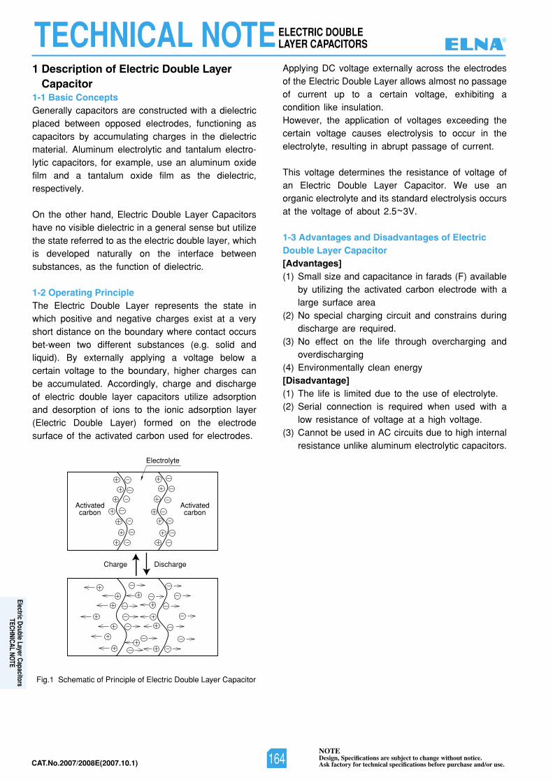
NOTEDesign, Specifications are subject to change without notice.Ask factory for technical specifications before purchase and/or use.CAT.No.2007/2008E(2007.10.1)
1 Description of Electric Double LayerCapacitor
1-1 Basic ConceptsGenerally capacitors are constructed with a dielectricplaced between opposed electrodes, functioning ascapacitors by accumulating charges in the dielectricmaterial. Aluminum electrolytic and tantalum electro-lytic capacitors, for example, use an aluminum oxidefilm and a tantalum oxide film as the dielectric,respectively.
On the other hand, Electric Double Layer Capacitorshave no visible dielectric in a general sense but utilizethe state referred to as the electric double layer, whichis developed naturally on the interface betweensubstances, as the function of dielectric.
1-2 Operating PrincipleThe Electric Double Layer represents the state inwhich positive and negative charges exist at a veryshort distance on the boundary where contact occursbet-ween two different substances (e.g. solid andliquid). By externally applying a voltage below acertain voltage to the boundary, higher charges canbe accumulated. Accordingly, charge and dischargeof electric double layer capacitors utilize adsorptionand desorption of ions to the ionic adsorption layer(Electric Double Layer) formed on the electrodesurface of the activated carbon used for electrodes.
Applying DC voltage externally across the electrodesof the Electric Double Layer allows almost no passageof current up to a certain voltage, exhibiting acondition like insulation.However, the application of voltages exceeding thecertain voltage causes electrolysis to occur in theelectrolyte, resulting in abrupt passage of current.
This voltage determines the resistance of voltage ofan Electric Double Layer Capacitor. We use anorganic electrolyte and its standard electrolysis occursat the voltage of about 2.5~3V.
1-3 Advantages and Disadvantages of ElectricDouble Layer Capacitor [Advantages](1) Small size and capacitance in farads (F) available
by utilizing the activated carbon electrode with alarge surface area
(2) No special charging circuit and constrains duringdischarge are required.
(3) No effect on the life through overcharging andoverdischarging
(4) Environmentally clean energy[Disadvantage](1) The life is limited due to the use of electrolyte.(2) Serial connection is required when used with a
low resistance of voltage at a high voltage.(3) Cannot be used in AC circuits due to high internal
resistance unlike aluminum electrolytic capacitors.
Fig.1 Schematic of Principle of Electric Double Layer Capacitor
Discharge
Activatedcarbon
Activatedcarbon
Electrolyte
Charge
TECHNICAL NOTEELECTRIC DOUBLELAYER CAPACITORS ®
164
Electric Double Layer CapacitorsTECHNICAL NOTE
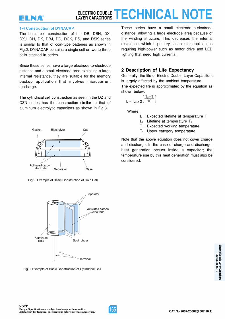
NOTEDesign, Specifications are subject to change without notice.Ask factory for technical specifications before purchase and/or use. CAT.No.2007/2008E(2007.10.1)
1-4 Construction of DYNACAPThe basic cell construction of the DB, DBN, DX,DXJ, DH, DK, DBJ, DC, DCK, DS, and DSK seriesis similar to that of coin-type batteries as shown inFig.2. DYNACAP contains a single cell or two to threecells stacked in series.
Since these series have a large electrode-to-electrodedistance and a small electrode area exhibiting a largeinternal resistance, they are suitable for the memorybackup application that involves microcurrentdischarge.
The cylindrical cell construction as seen in the DZ andDZN series has the construction similar to that ofaluminum electrolytic capacitors as shown in Fig.3.
These series have a small electrode-to-electrodedistance, allowing a large electrode area because ofthe winding structure. This decreases the internalresistance, which is primary suitable for applicationsrequiring high-power such as motor drive and LEDIighting that need high currents.
2 Description of Life ExpectancyGenerally, the life of Electric Double Layer Capacitorsis largely affected by the ambient temperature.The expected life is approximated by the equation asshown below:
Note that the above equation does not cover chargeand discharge. In the case of charge and discharge,heat generation occurs inside a capacitor; thetemperature rise by this heat generation must also beconsidered.
Fig.2 Example of Basic Construction of Coin Cell
Cap
CaseSeparatorActivated carbon
electrode
Gasket Electrolyte
Fig.3 Example of Basic Construction of Cylindrical Cell
Aluminumcase
Terminal
Seal rubber
Separator
Activated carbon electrode
L = L0 x 2
Where,L : Expected lifetime at temperature TL0 : Lifetime at temperature T0
T : Expected working temperatureT0 : Upper category temperature
T0 T———10 ))
TECHNICAL NOTEELECTRIC DOUBLELAYER CAPACITORS®
165
Electric Double Layer CapacitorsTECHNICAL NOTE
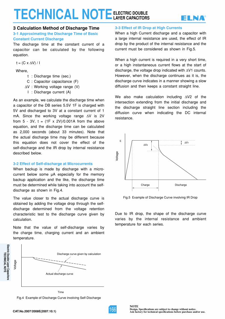
NOTEDesign, Specifications are subject to change without notice.Ask factory for technical specifications before purchase and/or use.CAT.No.2007/2008E(2007.10.1)
3 Calculation Method of Discharge Time3-1 Approximating the Discharge Time of BasicConstant Current DischargeThe discharge time at the constant current of acapacitor can be calculated by the followingequation.
t = (C x V) / I
Where,t : Discharge time (sec.)C : Capacitor capacitance (F)V : Working voltage range (V)I : Discharge current (A)
As an example, we calculate the discharge time whena capacitor of the DB series 5.5V 1F is charged with5V and discharged to 3V at a constant current of 1mA. Since the working voltage range V is 2Vfrom 5 - 3V, t = (1F x 2V)/0.001A from the aboveequation, and the discharge time can be calculatedas 2,000 seconds (about 33 minutes). Note thatthe actual discharge time may be different becausethis equation does not cover the effect of theself-discharge and the IR drop by internal resistancedescribed below.
3-2 Effect of Self-discharge at MicrocurrentsWhen backup is made by discharge with a micro-current below some µA especially for the memorybackup application and the like, the discharge timemust be determined while taking into account the self-discharge as shown in Fig.4.
The value closer to the actual discharge curve isobtained by adding the voltage drop through the self-discharge determined from the voltage retentioncharacteristic test to the discharge curve given bycalculation.
Note that the value of self-discharge varies bythe charge time, charging current and an ambienttemperature.
Time
Vol
tage
Actual discharge curve
Discharge curve given by calculation
Fig.4 Example of Discharge Curve involving Self-Discharge
3-3 Effect of IR Drop at High CurrentsWhen a high Current discharge and a capacitor witha large internal resistance are used, the effect of IRdrop by the product of the internal resistance and thecurrent must be considered as shown in Fig.5.
When a high current is required in a very short time,or a high instantaneous current flows at the start ofdischarge, the voltage drop indicated with V1 counts.However, when the discharge continues as it is, thedischarge curve indicates in a manner showing a slowdiffusion and then keeps a constant straight line.
We also make calculation including V2 of theintersection extending from the initial discharge andthe discharge straight line section including thediffusion curve when indicating the DC internalresistance.
Due to IR drop, the shape of the discharge curvevaries by the internal resistance and ambienttemperature for each series.
DischargeCharge
EV1
V2
Vol
tage
Fig.5 Example of Discharge Curve involving IR Drop
TECHNICAL NOTEELECTRIC DOUBLELAYER CAPACITORS ®
166
Electric Double Layer CapacitorsTECHNICAL NOTE
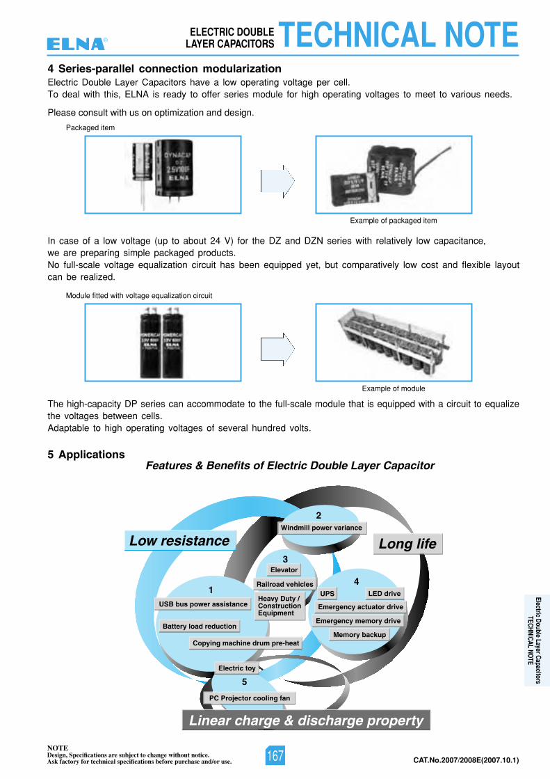
NOTEDesign, Specifications are subject to change without notice.Ask factory for technical specifications before purchase and/or use. CAT.No.2007/2008E(2007.10.1)
4 Series-parallel connection modularizationElectric Double Layer Capacitors have a low operating voltage per cell.To deal with this, ELNA is ready to offer series module for high operating voltages to meet to various needs.
5 Applications
In case of a low voltage (up to about 24 V) for the DZ and DZN series with relatively low capacitance,we are preparing simple packaged products.No full-scale voltage equalization circuit has been equipped yet, but comparatively low cost and flexible layoutcan be realized.
The high-capacity DP series can accommodate to the full-scale module that is equipped with a circuit to equalizethe voltages between cells.Adaptable to high operating voltages of several hundred volts.
1
2
3
4
5
Features & Benefits of Electric Double Layer Capacitor
Low resistance Long life
Linear charge & discharge property
Windmill power variance
Elevator
Railroad vehicles
Heavy Duty /ConstructionEquipment
LED drive
Memory backup
Emergency memory drive
Emergency actuator drive
UPS
PC Projector cooling fan
Electric toy
Copying machine drum pre-heat
USB bus power assistance
Battery load reduction
Example of packaged item
Module fitted with voltage equalization circuit
Example of module
Please consult with us on optimization and design.
Packaged item
TECHNICAL NOTEELECTRIC DOUBLELAYER CAPACITORS®
167
Electric Double Layer CapacitorsTECHNICAL NOTE
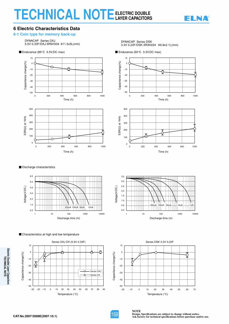
NOTEDesign, Specifications are subject to change without notice.Ask factory for technical specifications before purchase and/or use.CAT.No.2007/2008E(2007.10.1)
200uA 100uA 50uA 10uA200uA 100uA 50uA 10uA 1uA
Endurance (85 06(ecnarudnE)xamCD.V5.5C C 3.3V.DC max)
DYNACAP Series DXJ5.5V 0.33F/DXJ-5R5H334 11.5x5L(mm)
DYNACAP Series DSK3.3V 0.22F/DSK-3R3H224 6.8x2.1L(mm)
F22.0V3.3KSDseireS)F33.0V5.5(XDJXDseireS
Discharge characteristics
Characteristics at high and low temperature
)m(emitegrahcsiD)m(emitegrahcsiD
Temperature ( C)
Cap
acita
nce
chan
ge(%
)
Cap
acita
nce
chan
ge(%
)
Cap
acita
nce
chan
ge(%
)
Cap
acita
nce
chan
ge(%
)
ES
R(
) at
1kH
zV
olta
ge(V
.DC
.)
Vol
tage
(V.D
C.)
50
40
30
20
10
0
10
50
40
30
20
10
0
10
30 20 10 0 10 20 30 40 50 60 70 80 90
Temperature ( C)
20 10 0 10 20 30 40 50 60 70
Time (h)Time (h)
Time (h)Time (h)
50
40
30
20
10
0
10
0001008006004002000010080060040020
0 200 400 600 800 1000 0 200 400 600 800 1000
0
100
200
300
400
500
ES
R(
) at
1kH
z
0
100
200
300
400
500
0.0
1.0
2.0
3.0
4.0
5.0
6.0
0.0
0.5
1.0
1.5
2.0
2.5
3.5
3.0
1 10 100 1000 10000 1 10 100 1000 10000
50
40
30
20
10
0
10
Series DXJ
Series DX
6 Electric Characteristics Data6-1 Coin type for memory back-up
TECHNICAL NOTEELECTRIC DOUBLELAYER CAPACITORS ®
168
Electric Double Layer CapacitorsTECHNICAL NOTE
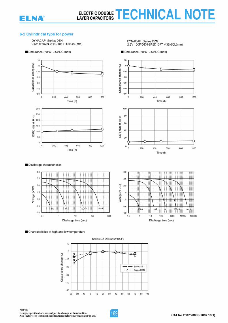
NOTEDesign, Specifications are subject to change without notice.Ask factory for technical specifications before purchase and/or use. CAT.No.2007/2008E(2007.10.1)
1A 1A5A 10mA 10mA100A 10A100mA 100mA
30 20 10 0 10 20 30 40 50 60 70 80 90
Discharge time (sec)Discharge time (sec)
Time (h)Time (h)
Time (h) Time (h)
Series DZ DZN(2.5V100F)
Vol
tage
(V.
DC
.)
Vol
tage
(V.
DC
.)
Cap
acita
nce
chan
ge(%
)
ES
R(m
) at
1kH
z
ES
R(m
) at
1kH
zC
apac
itanc
e ch
ange
(%)
Cap
acita
nce
chan
ge(%
)
Endurance (70 07(ecnarudnE)xamCD.V5.2C C 2.5V.DC max)
Discharge characteristics
Characteristics at high and low temperature
40
50
30
20
10
10
0
40
50
30
20
10
10
0
0 200 400 600 800 1000 0 200 400 600 800 1000
0 200 400 600 800 10000 200 400 600 800 1000
1 10 100 10000.11 10 100 10000.1 10000 100000
DYNACAP Series DZN2.5V 1F/DZN-2R5D105T 8x22L(mm)
DYNACAP Series DZN2.5V 100F/DZN-2R5D107T 35x50L(mm)
0
50
100
150
200
300
250
100
80
60
40
20
0
0.0
0.5
1.0
1.5
2.0
2.5
3.0
0.0
0.5
1.0
1.5
2.0
2.5
3.0
50
40
30
20
10
10
0
Series DZ
Series DZN
6-2 Cylindrical type for power
TECHNICAL NOTEELECTRIC DOUBLELAYER CAPACITORS®
169