ARYLENE ETHER SULFONE - Virginia Tech
264
SYNTHESIS AND CHARACTERIZATION OF SULFONATED POLY (ARYLENE ETHER SULFONE) COPOLYMERS via DIRECT COPOLYMERIZATION: CANDIDATES for PROTON EXCHANGE MEMBRANE FUEL CELLS by William L Harrison Dissertation submitted to the Faculty and the Graduate School of the Virginia Polytechnic Institute and State University in partial fulfillment of the requirements for the degree of DOCTOR OF PHILOSOPHY in Chemistry APPROVED: Dr. James E. McGrath, Chairman Dr. John G. Dillard Dr. Judy S. Riffle Dr. Allan R. Shultz Dr. Godson C. Nwokogu, Hampton University, Va December 3, 2002 Blacksburg, Virginia Keywords: Proton Exchange Membranes, Direct Copolymerization, Sulfonated Poly (arylene ether sulfone) Random Copolymers, Bisphenol Structure, Sulfonic Acid Sites, Poly (arylene ether sulfones), Fuel Cells Copyright 2002, William L. Harrison
Transcript of ARYLENE ETHER SULFONE - Virginia Tech
SYNTHESIS AND CHARACTERIZATION OF SULFONATED POLY (ARYLENE ETHER SULFONE) COPOLYMERS via DIRECT
COPOLYMERIZATION: CANDIDATES for PROTON EXCHANGE MEMBRANE FUEL CELLS
by
William L Harrison
Dissertation submitted to the
Faculty and the Graduate School of the
Virginia Polytechnic Institute and State University
in partial fulfillment of the requirements for the degree of
DOCTOR OF PHILOSOPHY
in
Chemistry
APPROVED:
Dr. James E. McGrath, Chairman
Dr. John G. Dillard
Dr. Judy S. Riffle
Dr. Allan R. Shultz
Dr. Godson C. Nwokogu, Hampton University, Va
December 3, 2002
Blacksburg, Virginia
Keywords: Proton Exchange Membranes, Direct Copolymerization, Sulfonated Poly
(arylene ether sulfone) Random Copolymers, Bisphenol Structure, Sulfonic Acid Sites,
Poly (arylene ether sulfones), Fuel Cells
Copyright 2002, William L. Harrison

SYNTHESIS AND CHARACTERIZATION OF SULFONATED POLY (ARYLENE ETHER SULFONE) COPOLYMERS via DIRECT
COPOLYMERIZATION: CANDIDATES for PROTON EXCHANGE MEMBRANE FUEL CELLS
William L. Harrison
Committee Chairman: Dr. James E. McGrath
Department of Chemistry
ABSTRACT
A designed series of directly copolymerized homo- and disulfonated copolymers
containing controlled degrees of pendant sulfonic acid groups have been synthesized via
nucleophilic step polymerization. Novel sulfonated poly (arylene ether sulfone)
copolymers using 4,4’-bisphenol A, 4,4’-biphenol, hexafluorinated (6F) bisphenol AF,
and hydroquinone, respectively, with dichlorodiphenyl sulfone (DCDPS) and 3,3’-
disodiumsulfonyl-4,4’-dichlorodiphenylsulfone (SDCDPS) were investigated. Molar
ratios of DCDPS and SDCDPS were systematically varied to produce copolymers of
controlled compositions, which contained up to 70 mol% of disulfonic acid moiety. The
goal is to identify thermally, hydrolytically, and oxidatively stable high molecular weight,
film-forming, ductile ion conducting copolymers, which had properties desirable for
proton exchange membranes (PEM) in fuel cells.
Commercially available bisphenols were selected to produce cost effective
alternative PEMs. Partially aliphatic bisphenol A and hexafluorinated (6F) bisphenol AF
produced amorphous copolymers with different thermal oxidative and surface properties.
Biphenol and hydroquinone was utilized to produce wholly aromatic copolymers.
The sulfonated copolymers were prepared in the sodium-salt form and converted
to the acid moiety via two different methodologies and subsequently investigated as
proton exchange membranes for fuel cells. Hydrophilicity increased with the level of

iii
disulfonation, as expected. Moreover, water sorption increased with increasing mole
percent incorporation of SDCDPS. The copolymers’ water uptake was a function of both
bisphenol structure and degree of disulfonation. Furthermore, the acidification
procedures were shown to influence the Tg values, water uptake, and conductivity of the
copolymers. Atomic force microscopy (AFM) in the tapping mode confirmed that the
morphology of the copolymers could be designed to display nanophase separation in the
hydrophobic and hydrophilic (sulfonated) regions. Morphology with either co-
continuous hydrophobic or hydrophilic domains could be attained for all the sulfonated
copolymers. The degree of disulfonation required for continuity of the hydrophilic phase
varied with biphenol structure.
Proton conductivity values for the sulfonated copolymers, under fully hydrated
conditions, were a function of bisphenol and degree of sulfonation. However, at
equivalent ion exchange capacities the proton conductivities were comparable. A careful
balance of copolymer composition and acidification method was necessary to afford a
morphology that produced ductile films, which were also sufficiently proton conductive.
The copolymers of optimum design produced values of 0.1 S/cm or higher, which were
comparable to the commercial polyperfluorosulfonic acid material Nafion™ control.

iv
Dedicated to my loving wife, Dionne, and our children, Lamonte’ and Leah,
for
their support, understanding, and encouragement

v
Acknowledgements
I would like to take this opportunity to express my sincere gratitude to my
research advisor, Dr. James E. McGrath, for his encouragement, guidance and inspiration
throughout this work. I have exceedingly benefited from his vast knowledge, lasting
enthusiasm, and exceptional personality. I would also like to thank the members of my
advisory committee, Dr. John G. Dillard, Dr. Judy S. Riffle, Dr. Allan R. Shultz, and Dr.
Godson C. Nwokogu for their support. Additional thanks are given to Dr. Shultz for his
suggestions and discussions during the many Saturday morning group meetings.
I would also like to acknowledge the valuable assistance of Mr. Tom Glass
(NMR), Mr. Frank Cromer (XPS), Mr. Kerry O’Connor (intrinsic viscosity
measurements), and Dr. Yu Sueng Kim (Atom Force Microscopy).
I greatly appreciate and cherish the friendships developed with my former and
present colleagues at Virginia Tech. I’m indebted to Drs. B. Sue Mecham, M (Sankar)
Sankarapandian, H. K. Shobha, Charles Tchatchoua, Isaac Farr, Sheng Wang, Debi
Dunson, Dave Polk, Y.T. Hong, Qing Ji, and Hossein Ghassemi, for their assistance
during my research. Special thanks are extended to the “Fuel Cell Division”: Drs. Feng
Wang, Jeff Mecham, Nazan Gunduz, Yu Sueng Kim, V. Bhanu, Mr. Mike Hickner, Mr.
Brian Einsla, and Mr. Kent Wiles, for their invaluable discussions and assistance. Many
thanks are owed to Dr. Feng “Magic” Wang for his helpful suggestions and continuous
encouragement.
I thank Mr. Michael Hickner and Mrs. X. Li for their invaluable assistance with
conductivity measurements of membranes, and Dr. Y.S. Kim for GPC and AFM
measurements.
I would like to thank the ladies in the Science and Technology Center for their
friendship and help with various tasks over the years. Mrs. Laurie Good, Mrs. Millie
Ryan, and Mrs. Esther Brann have all contributed to my success in the graduate program
through encouragement, cheerfulness, and kindness.
I would like to thank my friends, Ms. Darlene M. Eberhardt, Mr. Andre’ M.
Green, Dr. Belhu Metaferia, and Dr. Cherese Winstead-Allen, for their support and
encouragement throughout my graduate education. The five of us have experienced a lot

vi
together—beginning at Hampton University in 1995, and your friendship was very
important to our collective success.
My loving wife, Dionne, deserves the most recognition by far. A working mother
of two, she had her own obstacles and ambitions, yet was available to assist me at a
moment’s notice. I could not have made it without her love and understanding. Also, to
my son Lamonte’, I thank you for his pleasant disposition and understanding. I would
like to thank my new daughter Leah, who unknowingly has rejuvenated my pleasure in
the simple things. I would also like to thank my entire family for their love, prayers, and
assistance that have aided me to this point of my life.
Finally I am grateful to my Lord Jesus Christ, who continues to be my refuge and
my guiding light.

vii
SYNTHESIS AND CHARACTERIZATION OF SULFONATED POLY (ARYLENE ETHER SULFONE) COPOLYMERS via DIRECT
COPOLYMERIZATION: CANDIDATES for PROTON EXCHANGE MEMBRANE FUEL CELLS
Table of Content
CHAPTER 1 ....................................................................................................................... 1
I. LITERATURE REVIEW: INTRODUCTION TO FUEL CELLS ............... 1
1.1 Fuel Cells ........................................................................................................ 1
1.1.1 Phosphoric Acid Fuel Cells (PAFC)........................................................ 3
1.1.2 Molten Carbonate Fuel Cells (MCFC) .................................................... 5
1.1.3 Solid Oxide Fuel Cells (SOFC) ............................................................... 7
1.1.4 Alkaline Fuel Cells (AFC) ....................................................................... 9
1.1.5 Proton Exchange Membrane Fuel Cells (PEMFC)................................ 11
1.2 Proton Exchange Membrane Candidates ...................................................... 14
1.2.1 Styrene and Derivatized Styrene PEM .................................................. 15
1.2.2 Perfluorinated Copolymers .................................................................... 20
1.2.3 Post-Sulfonated Aromatic Engineering Thermoplastics........................ 27
1.2.3.1 Poly (arylene ethers) ........................................................................ 27
(1) Poly(Arylene Ether Sulfones) ................................................................. 28
(2) Poly(Arylene Ether Ketones) .................................................................. 33
1.2.4 Poly (Benzyl Sulfonic Acid) Siloxanes (PBSS) .................................... 35
1.2.5 Poly(phenylquinoxalines) (PPQ) ........................................................... 36
1.2.6 Poly (Phenylene Oxide) (PPO) .............................................................. 37
1.3 Direct, Step-Growth Polymerization of Sulfonated Monomers ................... 38
1.3.1 “Direct” Sulfonated Polyimides Copolymers ........................................ 38
1.3.2 “Direct” Sulfonated Poly (Arylene Ether) Copolymers......................... 44
(1) Poly(arylene ether sulfones).................................................................... 44
(2) Poly(arylene ether ketones)............................................................... 49
(3) Poly(arylene ether phosphine oxide) ................................................ 51
1.3.3 Poly(arylene sulfide sulfones) (PSS) ..................................................... 52
viii
1.4 Miscellaneous Blends and Nanocomposites................................................. 54
1.4.1 Polymer Blends............................................................................................ 54
1.4.2 Additives and Dopants................................................................................. 56
II. LITERATURE REVIEW: POLY (ARYLENE ETHER) SYNTHESIS ..... 59
1.5 The Ullman Reaction .................................................................................... 59
1.6 Nickel Coupling Reaction............................................................................. 61
1.7 Friedel-Crafts Electrophilic Substitution ...................................................... 61
1.8 Nucleophilic Aromatic Substitution ............................................................. 65
1.4.1 Strong Base Approach ................................................................................. 69
1.4.2 Weak Base Approach................................................................................... 72
CHAPTER 2 ..................................................................................................................... 77
EXPERIMENTAL........................................................................................................ 77
2.1 Solvent Purification ...................................................................................... 77
2.1.1 N,N-Dimethylacetamide (DMAc) ......................................................... 77
2.1.2 N-Methyl-2-Pyrrolidone (NMP)............................................................ 78
2.1.3 Fuming Sulfuric Acid ............................................................................ 78
2.1.4 Toluene .................................................................................................. 79
2.1.5 Ethanol or Ethyl Alcohol ....................................................................... 79
2.1.6 Methanol or Methyl Alcohol ................................................................. 80
2.1.7 Isopropyl Alcohol or 2-Propanol or Isopropanol................................... 80
2.1.8 1,2-Dichloroethane (DCE)..................................................................... 81
2.1.9 1,1,2-Trichloroethane (TCE) ................................................................. 81
2.2 Reagents and Purification of Monomers....................................................... 82
2.2.1 Bisphenol A (Bis A) or 2,2’-bis(4-hydroxyphenol)propane or 4,4'-
isopropylidenediphenol.......................................................................... 82
2.2.2 4,4’-Biphenol (BP)................................................................................. 82
2.2.3 6F-Bisphenol A (6F) or 4,4'-(hexafluoroisopropylidene) diphenol....... 83
2.2.4 Hydroquinone (HQ) or 1,4-benzene diol ............................................... 83
2.2.5 4-4’-Dichlorodiphenyl sulfone (DCDPS) or Bis (4-chlorophenyl)
sulfone.................................................................................................... 84
2.2.6 Potassium Carbonate (Anhydrous) ........................................................ 84
ix
2.2.7 4,4’-Difluorodiphenyl Sulfone (DFDPS) or Bis (4-fluorophenyl) sulfone
............................................................................................................... 85
2.2.8 Chlorosulfonic acid................................................................................ 85
2.2.9 Chlorotrimethylsilane or Trimethylchlorosilane.................................... 86
2.3 Monomer Synthesis ...................................................................................... 87
2.3.1 Sodium Salt of 3,3’-Disulfonated –4,4’-( bis-isopropylidene) diphenol or
87
2.3.2 Sodium Salt of 3,3’-Disulfonated-4,4’- Biphenol or Sulfonated Biphenol
88
2.3.3 Sodium Salt of 3,3’-Disulfonated-4,4’-(bis-hexafluoroisopropylidene)
diphenol or Sulfonated 6F-Bisphenol A ................................................ 90
2.3.4 Sodium Salt of 3,3’-Disulfonated-4,4’-dichlorodiphenyl sulfone
(SDCDPS).............................................................................................. 91
2.3.5 Sodium Salt of 3,3’-Disulfonated-4,4’-difluorodiphenyl sulfone
(SDFDPS) .............................................................................................. 92
2.3.6 Synthesis of 4,4’-Difluorodiphenyl Sulfone .......................................... 94
2.4 Copolymer Synthesis .................................................................................... 95
2.4.1 DCDPS/SDCDPS Copolymer Synthesis ............................................... 95
2.4.2 DFDPS/SDFDPS Copolymer Synthesis ................................................ 96
2.5 Polymer Post - Sulfonation ........................................................................... 98
2.6 Characterization .......................................................................................... 100
2.6.1 Nuclear Magnetic Resonance (NMR) Spectroscopy ........................... 100
2.6.2 Fourier Transform Infrared (FTIR) Spectroscopy ............................... 100
2.6.3 Gel Permeation Chromatography (GPC) or Size Exclusion
Chromatography (SEC) ....................................................................... 100
2.6.4 Intrinsic Viscosity Determinations ([η]).............................................. 101
2.6.5 Thermogravimetric Analysis (TGA).................................................... 101
2.6.6 Differential Scanning Calorimetry (DSC) ........................................... 102
2.6.7 Mass Spectroscopy (MS) ..................................................................... 102
2.6.8 Elemental Analysis .............................................................................. 102
2.6.9 Non-Aqueous Potentiometric Titration................................................ 102

x
2.6.10 Film Preparation................................................................................... 103
2.6.11 Water Sorption/Uptake ........................................................................ 104
2.6.12 Conductivity Measurements ................................................................ 104
2.6.13 Electron Spectroscopy for Chemical Analysis (ESCA)....................... 105
CHAPTER 3 ................................................................................................................... 106
RESULTS AND DISCUSSION................................................................................. 106
3.1 Introduction................................................................................................. 106
3.1.1 Sulfonated Bisphenols ......................................................................... 107
3.1.2 Sulfonated Dihalides............................................................................ 118
3.2 Polymer Synthesis....................................................................................... 126
3.2.2 Synthesis of Homopolymers ................................................................ 126
3.2.2 Synthesis of Sulfonated Copolymers ................................................... 129
3.3 Polymer Characterization............................................................................ 139
3.3.1 Fourier Transform Infrared Spectroscopy (FTIR) ............................... 139
3.3.2 1H NMR Spectroscopy......................................................................... 141
3.3.3 Differential Scanning Calorimetry (DSC) ........................................... 147
3.3.4 Thermogravimetric Analysis (TGA).................................................... 153
3.3.5 Solution Properties............................................................................... 157
3.3.6 Water Uptake/Sorption ........................................................................ 159
3.3.7 Proton Conductivity ............................................................................. 165
3.3.8 Morphology.......................................................................................... 172
3.3.9 Surface Analysis (ESCA) of Directly Sulfonated 6F Copolymers...... 178
CHAPTER 4 ............................................................................................................... 182
Influence of Bisphenol Structure on the Direct Synthesis of Sulfonated Poly(arylene
ether) Copolymers. I .................................................................................. 182
CHAPTER 5 ................................................................................................................... 221
SUMMARY AND CONCLUSIONS ......................................................................... 221
CHAPTER 6 ................................................................................................................... 224
SUGGESTED FUTURE WORK ............................................................................... 224
APPENDIX .................................................................................................................... 226
SYNTHESIS OF SULFONATED POLY (ARYLENE ETHER SULFONES) VIA 226

xi
CHLOROSULFONIC ACID...................................................................................... 226
Table of Figures
Figure 1. Schematic of a fuel cell and related electrochemical reactions to produce
electricity........................................................................................................ 2
Figure 2a. Components of a single-cell phosphoric acid fuel cell. .................................. 4
Figure 2b. Schematic of a molten carbonate fuel cell .................................................. 6
Figure 2c. Principle of operation: high-temperature solid oxide electrolyte fuel. ........... 8
Figure 2d. Operation of an alkaline fuel cell.................................................................. 10
Figure 3. Methanol oxidation via platinum catalyst..................................................... 12
Figure 4. Preparation of polystyrene-g-poly (sodium styrenesulfonate)...................... 16
Figure 5. Reported structure of DAIS-Analytic Triblock PEM. .................................. 17
Figure 5a. Reported molecular structure of Ballard Advanced Materials Corporation’s
BAM3G........................................................................................................ 18
Figure 6. Idealized chemical structure of linear and cross-linked sulfonated
phenolformaldehyde .................................................................................... 19
Figure 7. Proposed structure of Nafion and Dow XUS perfluorinated copolymers,.
...................................................................................................................... 21
Figure 7a. Proposed synthesis of perfluorinated comonomers utilized for Nafion and
Dow XUS copolymers. .............................................................................. 23
Figure 7b. Ionic cluster network model for perfluorosulfonic acid copolymer. ............ 25
Figure 7c. Redistribution of ionic sites/cluster during dehydration cycles. ................... 26
Figure 8. Generic representation of poly (arylene ethers)............................................ 28
Figure 9. Sulfonation of Udel Polysulfone................................................................. 28
Figure 10. Postulated Mechanism and Intermediates of Toluene Sulfonation via Sulfur
Trioxide........................................................................................................ 31
Figure 11. Synthetic route to sulfonated poly (ether sulfones) via metalation............... 32
Figure 12. Crosslinking of sulfonated PAES using 1,1’-carbonyl diimidazole ............. 33
Figure 13. Chlorosulfonated hexafluoroisopropylidene containing poly (arylene ether
ketone).......................................................................................................... 34

xii
Figure 14. Proposed chemical structure of poly (benzyl sulfonic acid) siloxane........... 35
Figure 15. Structure of poly (phenylquinoxalines). ....................................................... 36
Figure 16. Chemical Structure of 2,6-diphenyl phenol .................................................. 37
Figure 17. Chemical structure of 4,4’-diamino-2,2’-biphenyldisulfonic acid (BDSA). 39
Figure 18. Sulfonated diamines investigated by Gunduz, et al...................................... 41
Figure 19. Sulfonated polyimide copolymer based on BDSA. ...................................... 42
Figure 20. Structure of novel phosphine oxide based sulfonated diamine..................... 43
Figure 21. Synthesis of 3,3’-disulfonated 4,4’-dichlorodiphenyl sulfone...................... 45
Figure 22. Synthesis of amine-terminated sulfonated poly (arylene ether sulfone)
oligomers...................................................................................................... 47
Figure 23. Synthesis of polyimide-block-sulfonated poly(arylene ether sulfone) ......... 48
Figure 24. Structure of 3,3’-disulfonated 4,4’-difluorodiphenyl ketone........................ 49
Figure 25. Sulfonated poly (arylene ether ketone) copolymers via direct
copolymerization. ........................................................................................ 50
Figure 26. Structure of 6F-containing sulfonated poly (ether ketone) via direct
copolymerization.......................................................................................... 51
Figure 27. Structure of sulfonated 4,4’-bis(phenyl) phenyl phosphine oxide................ 51
Figure 28. Influence of aging temperature exposure for 30 minutes on intrinsic viscosity
of sulfonated PSS......................................................................................... 53
Figure 29. Ullman synthesis of poly (arylene ethers). ................................................... 60
Figure 30. Generation of sulfonylium cation. ................................................................ 63
Figure 31. Synthesis of poly (arylene ether sulfones) via Electrophilic Substitution. ... 64
Figure 32. Nucleophilic aromatic substitution of chlorobenzene................................... 65
Figure 33. Influence of activating group(s) on nucleophilic aromatic substition .......... 66
Figure 34. The rate determining step of nucleophilic aromatic substitution reaction.... 67
Figure 35. Strong base-nucleophilic aromatic substitution synthesis of poly (arylene
ethers)........................................................................................................... 70
Figure 35a. Hydrogen bonding of a phenol and a phenolate. .......................................... 71
Figure 36. Bisphenate route to polysulfones via weak base process.............................. 72
Figure 37. Monophenolate mechanism to polysulfone via weak base process.............. 73
Figure 38. Synthesis of poly (arylene ethers) via silyl ether displacement .................... 76

xiii
Figure 38a. Silyl ether displacement reaction mechanism............................................... 76
Figure 39. Synthesis of novel disulfonated bisphenols. ................................................. 89
Figure 40. General synthesis of disodium salt of the disulfonated sulfone dihalide
monomers..................................................................................................... 93
Figure 41. Synthesis of difluorodiphenyl sulfone from dichlorodiphenyl sulfone. ....... 94
Figure 42. Synthesis of sulfonated poly (arylene ether sulfone) copolymers via direct
polymerization. ............................................................................................ 97
Figure 43 Synthesis of sulfonated poly(arylene ether sulfone)s via the silyl ester of
chlorosulfonic acid....................................................................................... 99
Figure 44. Schematic of Conductivity Cell .................................................................. 105
Figure 45. Structures of bisphenols utilized in this research........................................ 108
Figure 46. A poly (arylene ether sulfone) using a substituted bisphenol ..................... 109
Figure 47. Electrophilic aromatic substitution of benzene in hot sulfuric acid............ 110
Figure 48. Proposed (basic form) products resulting from the sulfonation of bisphenol
A, during the reaction progression (6 hours). ............................................ 111
Figure 49. Possible acid catalyzed cleavage of the isopropylidene group in Bisphenol A.
.................................................................................................................... 112
Figure 50. Proton NMR of basic-form product (disodium salt of monosulfonated
phenolate) isolated from the sulfonation of bisphenol A in concentrated
sulfuric acid. D2O is the solvent. ............................................................... 113
Figure 51. Pi-electron density for some substituted benzenes ..................................... 115
Figure 52. Mass Spectrum of sulfonated 6F bisphenol A ............................................ 116
Figure 53. 1H NMR of the aromatic region of (a) 6F bisphenol A and (b) sulfonated 6F
bisphenol A salt.......................................................................................... 117
Figure 54. The SDCDPS elemental analysis: atomic composition as a function of
monomer work-up...................................................................................... 120
Figure 55. 1H NMR of 3,3’-disodium-4,4’-disulfonated dichlorodiphenyl sulfone .... 122
Figure 56. 13C NMR of 3,3’-disodium-4,4’-disulfonated dichlorodiphenyl sulfone ... 122
Figure 57. Mass spectrum of 3,3’-disodium sulfonated-4,4’-dichlorodiphenyl sulfone
(SDCDPS).................................................................................................. 123
Figure 58. 1H NMR of 3,3’-disodium sulfonated-4,4’-difluorodiphenyl sulfone ........ 125

xiv
Figure 59. Repeat unit of each control poly (arylene ether sulfone). ........................... 127
Figure 60. Synthesis of hydroquinone based sulfonated poly (arylene ether sulfone)
copolymers via direct copolymerization.................................................... 130
Figure 61. Sulfonated poly (sulfide sulfone) via direct copolymerization................... 135
Figure 62. Influence of the degree of disulfonation on the FT-IR of sulfonated poly
(arylene ether sulfone) copolymers............................................................ 140
Figure 63. 1H NMR and peak assignments of 6F-30 sulfonated copolymer................ 142
Figure 64. Synthesis of t-butyl phenyl terminated sulfonated poly (arylene ether
sulfone) via direct copolymerization. ........................................................ 144
Figure 65. 1H NMR of t-butylphenyl terminated biphenol-based sulfonated poly
(arylene ether sulfone) copolymers with controlled molecular weight ..... 146
Figure 66. Aggregation of ionic species in the EMH model........................................ 149
Figure 67. Influence of the degree of sulfonation on the glass transition temperature of
biphenol-based sulfonated poly (arylene ether sulfone) copolymers. ....... 152
Figure 68. TGA thermogram of weight loss of acid-form and salt-form BP-60 in
Nitrogen. .................................................................................................... 156
Figure 69. Schematic representation of water sources and movement in PEMFCs..... 159
Figure 70. Tapping mode-AFM micrograph of acid-form biphenol-based sulfonated
poly (arylene ether sulfone) copolymers.................................................... 173
Figure 71. Tapping mode –AFM phase image of 6F sulfonated copolymers (a) 6FSH-50
and (b) 6FSH-60. ....................................................................................... 175
Figure 72. Depiction of perfluorosulfonic acid membrane surface composition in
contact with water vapor and with liquid water (based on contact angle
measurements) ........................................................................................... 178
Figure 73. ESCA (XPS) survey scan of the surface atomic composition of 6F-50
acidified film.............................................................................................. 181
Figure A. Synthesis of sulfonated poly (arylene ether sulfones) via trimethyl silyl-
derivative of chlorosulfonic acid. .............................................................. 227
Figure B. In situ generation of trimethylsilyl chlorosulfonate.................................... 231
Figure C1. Infrared spectra of bisphenol A based poly (arylene ether sulfones) with
various degrees of sulfonation. .................................................................. 233

xv
Figure C2. FTIR spectra of post-sulfonated biphenol based poly (arylene ether sulfone)
with different degrees of sulfonation ......................................................... 234
Figure C3. Infrared spectra of 6Fbisphenol A-based poly (arylene ether sulfones) with
various degrees of sulfonation ................................................................... 235
Figure D. 1H NMR of sulfonated biphenol based-poly (arylene ether sulfone). ........ 236
Figure E. Graph of sulfonation efficiency (actual degree of sulfonation) as a function
of chlorosulfonic acid concentration.......................................................... 243
Figure F. Thermogravimetric analysis (TGA) of post-sulfonated biphenol based
poly(arylene ether sulfone) ........................................................................ 245
xvi
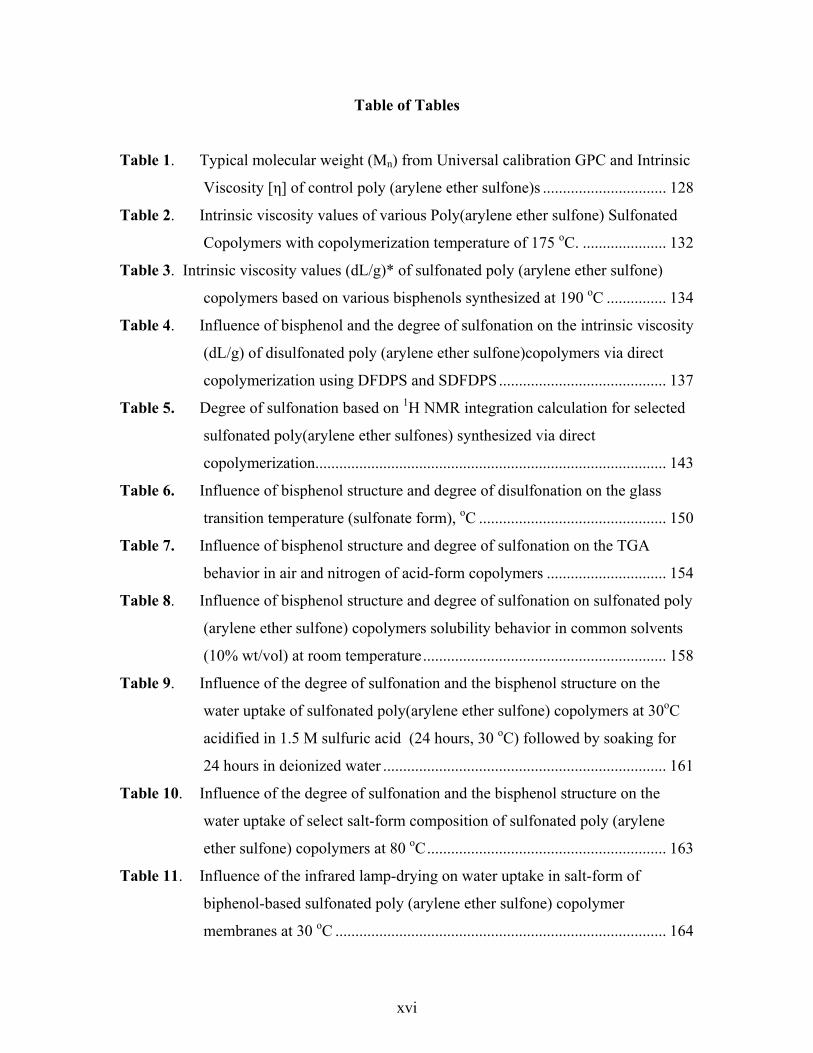
Table of Tables
Table 1. Typical molecular weight (Mn) from Universal calibration GPC and Intrinsic
Viscosity [η] of control poly (arylene ether sulfone)s ............................... 128
Table 2. Intrinsic viscosity values of various Poly(arylene ether sulfone) Sulfonated
Copolymers with copolymerization temperature of 175 oC. ..................... 132
Table 3. Intrinsic viscosity values (dL/g)* of sulfonated poly (arylene ether sulfone)
copolymers based on various bisphenols synthesized at 190 oC ............... 134
Table 4. Influence of bisphenol and the degree of sulfonation on the intrinsic viscosity
(dL/g) of disulfonated poly (arylene ether sulfone)copolymers via direct
copolymerization using DFDPS and SDFDPS.......................................... 137
Table 5. Degree of sulfonation based on 1H NMR integration calculation for selected
sulfonated poly(arylene ether sulfones) synthesized via direct
copolymerization........................................................................................ 143
Table 6. Influence of bisphenol structure and degree of disulfonation on the glass
transition temperature (sulfonate form), oC ............................................... 150
Table 7. Influence of bisphenol structure and degree of sulfonation on the TGA
behavior in air and nitrogen of acid-form copolymers .............................. 154
Table 8. Influence of bisphenol structure and degree of sulfonation on sulfonated poly
(arylene ether sulfone) copolymers solubility behavior in common solvents
(10% wt/vol) at room temperature............................................................. 158
Table 9. Influence of the degree of sulfonation and the bisphenol structure on the
water uptake of sulfonated poly(arylene ether sulfone) copolymers at 30oC
acidified in 1.5 M sulfuric acid (24 hours, 30 oC) followed by soaking for
24 hours in deionized water ....................................................................... 161
Table 10. Influence of the degree of sulfonation and the bisphenol structure on the
water uptake of select salt-form composition of sulfonated poly (arylene
ether sulfone) copolymers at 80 oC............................................................ 163
Table 11. Influence of the infrared lamp-drying on water uptake in salt-form of
biphenol-based sulfonated poly (arylene ether sulfone) copolymer
membranes at 30 oC ................................................................................... 164

xvii
Table 12A. Influence of Degree of Sulfonation on Several Features of Bisphenol A
based Copolymers...................................................................................... 168
Table 12B. Influence of Degree of Sulfonation on Several Features of Biphenol based
Copolymers ................................................................................................ 169
Table 12C. Influence of Degree of Sulfonation on Several Features of 6F Bisphenol A
based Copolymers...................................................................................... 170
Table 12D. Influence of Degree of Sulfonation on Several Features of Hydroquinone
based Copolymers...................................................................................... 171
Table 13A Influence of acidification method on water uptake and conductivity of select
bisphenolA-based sulfonated poly (arylene ether sulfone) copolymers .... 176
Table 13B Influence of acidification method on water uptake and conductivity of select
biphenol-based sulfonated poly (arylene ether sulfone) copolymers ........ 177
Table 13C Influence of acidification method on water uptake and conductivity of select
6F bisphenol A-based sulfonated poly (arylene ether sulfone) copolymers
.................................................................................................................... 177
Table 14 Influence of the degree of disulfonation in 6F-based poly(arylene ether
sulfone) copolymers and acidification treatment on the fluorine surface
content* as determined by ESCA. (%Fluorine)......................................... 179
Table A. GPC and Intrinsic Viscosity Characterization of Bisphenol A (Bis A), 6F-
Bisphenol A (6F) and Biphenol (BP) based Poly(arylene ether sulfone)
Homopolymers........................................................................................... 230
Table B. Averaged intrinsic viscosity data of poly (arylene ether sulfones) and
sulfonated poly (arylene ether sulfones) via chlorotrimethylsilane and
chlorosulfonic acid with different degrees of sulfonation ......................... 232
Table C1. Characterization of sulfonated bisphenol A-based poly(arylene ether sulfone)
using chlorosulfonic acid ........................................................................... 239
Table C2. Characterization of sulfonated biphenol-based poly(arylene ether sulfone)
using chlorosulfonic acid ........................................................................... 240
Table C3. Characterization of sulfonated 6F bisphenol A-based poly(arylene ether
sulfone) using chlorosulfonic acid ............................................................. 241
Table D. Determination of Degree of Sulfonation via Elemental Analysis .............. 242

1
CHAPTER 1
I. LITERATURE REVIEW: INTRODUCTION TO FUEL CELLS
The challenge of continually meeting the increasing world energy needs of its
inhabitants will be one of the most important tasks that our world will face in the twenty-
first century. Current energy sources are being depleted at high rates due to the growth of
the world’s population and its desire(s) to live at a high level of comfort. Petroleum is
the world’s most prevalent fuel. However, fossil fuels are becoming scarcer and their
burning produces emissions that pollute the air. Furthermore, fossil fuels are not a
renewable energy source.
Renewable and environmentally friendly energy sources will be essential for an
ever-changing and populous planet. Solar power, hydropower, and wind power systems
have been employed to complement current electric power sources. Arguably, the most
attractive alternative energy sources are fuel cells. Hydrogen is used to produce energy
by combining with oxygen in a fuel cell. Hydrogen is the cleanest, most sustainable and
renewable energy carrier1. Fuel cells are viable, renewable, and environmentally friendly
energy sources that do not require any special environmental conditions as do the
aforementioned renewal energy devices.
1.1 Fuel Cells
Fuel cells are electrochemical devices that convert the chemical energy of
reaction from a fuel directly into electrical energy2,3. Fuel cells are environmentally
1 Cheng, H.M.; Yang, Q.H.; Liu, C., Carbon 2001, 39 (10), 1447. 2 Appleby, A. J., Ed. Fuel Cells: Trends in Research and Applications; Hemisphere Publishing Corp.: New York, 1987; p.281 3 Zalbowitz, M.; Thomas, S. "Fuel Cells: Green Power," Department of Energy, 1999 LA-UR-99-3231.
2
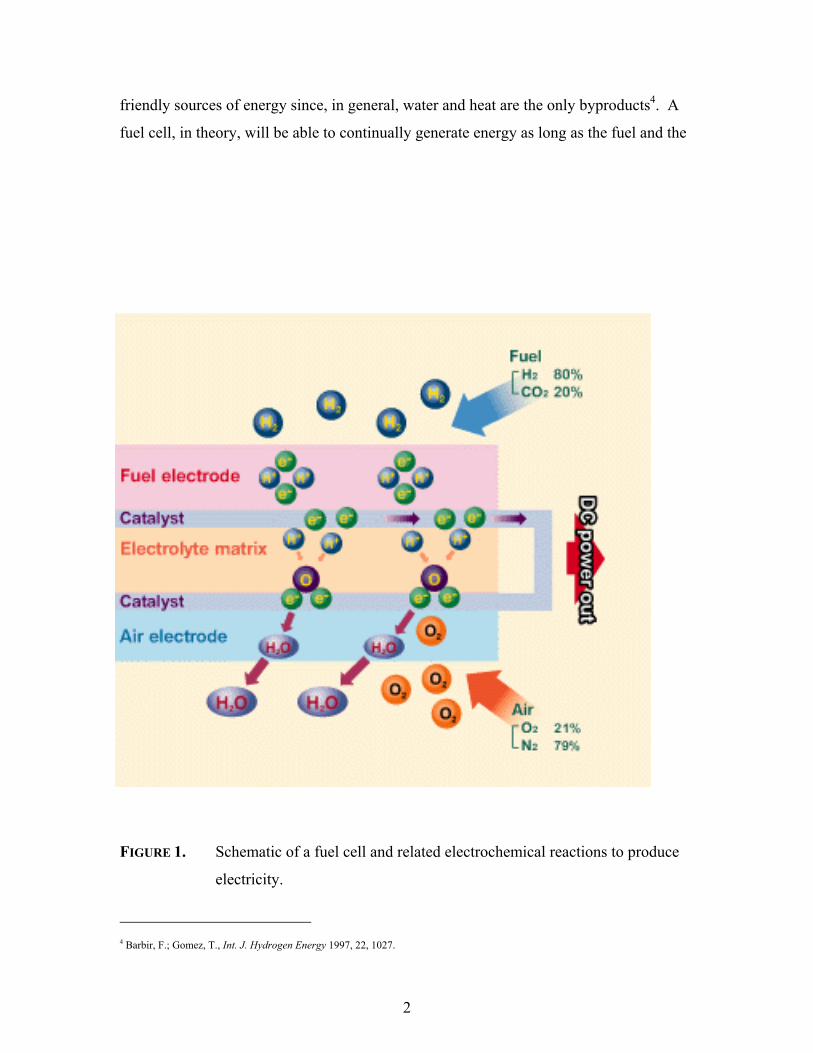
friendly sources of energy since, in general, water and heat are the only byproducts4. A
fuel cell, in theory, will be able to continually generate energy as long as the fuel and the
FIGURE 1. Schematic of a fuel cell and related electrochemical reactions to produce
electricity.
4 Barbir, F.; Gomez, T., Int. J. Hydrogen Energy 1997, 22, 1027.

3
oxidant are provided to the cell. This is distinctly different from typical batteries, which
are merely energy storage devices5. Since it is a storage appliance, the battery is dead (or
discharged) when the stored reactants are exhausted6. The fuel for fuel cells is stored
externally to the actual device, and therefore, will not become internally depleted.
Fuel cells operate without combustion, so they are virtually pollution free. Since
the fuel is converted directly to electricity, a fuel cell has the potential to operate at much
higher efficiencies than internal combustion engines, extracting more electricity from the
same amount of fuel. Fuel cells are mechanically ideal because these devices have no
moving parts - making them quiet and reliable sources of power.
There are essentially five fuel cell systems, each with its distinct electrochemical
reaction and operation requirements. The different fuel cells are generally classified by
the electrolyte used. They are: phosphoric acid fuel cells (PAFC), molten carbonate fuel
cells (MCFC), solid oxide fuel cells (SOFC), alkaline fuel cells (AFC), and proton
exchange membrane fuel cells (PEMFC). A brief general overview of each of these
systems will be presented here, with most emphasis on the PEMFC systems.
1.1.1 Phosphoric Acid Fuel Cells (PAFC)
Phosphoric acid fuel cells use concentrated (100%) phosphoric acid (H3PO4)
contained in a silicon carbide matrix as its electrolyte7. The typical operating
temperatures for phosphoric acid fuel cells are 150 oC to 220 oC. At temperatures below
this range phosphoric acid is a poor proton conductor and carbon monoxide poisoning of
the platinum electrocatalyst reduces the performance of the cell5,8. Platinum alloys have
also been investigated as electrochemical catalysts9,10. The half-reactions for a PAFC
are:
5 Hirschenhofer, J.H.; Stauffer, D.B.; Engleman, R.R., Fuel Cells: A Handbook for the Department of Energy; B/T Books: Orinda,
CA, 1996; p.1-1. 6 Liebhafsky, H.A.; Cairns, E..J., Fuel Cells and Fuel Batteries, John Wiley and Sons, Inc., New York1968; p.7 7 Appleby, A. J., Ed. Fuel Cells: Trends in Research and Applications; Hemisphere Publishing Corp.: New York, 1987. 8 Appleby, A.J.; Foulks, F.R., Fuel Cell Handbook, Van Nostrand Reinhold, New York, 1989. 9 Beard, B.C.; Ross, P.N., J. Electrochem. Soc. 1986, 133, 1839. 10 Glass, J.T.; Cahen, G.L.; Stoner, G.E.; Taylor, E.J., J. Electrochem. Soc. 1987, 134, 58.

4
Anode: H2 → 2H+ + 2e- Eqn 1
Cathode: ½ O2 + 2H+ + 2e- → H2O Eqn 2
Overall: H2 + ½ O2 → H2O Eqn 3
PAFCs are being developed as stationary or utility power devices5. The apparent
simplicity in the actual application of phosphoric acid fuel cells is hampered by the
gradual leakage of phosphoric acid by currently available components11. A depiction of a
phosphoric acid fuel cell is given in Figure 2a.
FIGURE 2A. Components of a single-cell phosphoric acid fuel cell.
11 Carrette, L.; Friedrich, K.A.; Stimming, U., J. ChemPhysChem 2000, 1, 162-193.

5
1.1.2 Molten Carbonate Fuel Cells (MCFC)
Molten carbonate fuel cells (MCFC) operate at high temperatures, typically 600 oC to 700 oC, and use highly conductive molten salts12. Molten carbonate fuel cells
usually employ a combination of sodium carbonate (Na2CO3) and potassium carbonate
(K2CO3) to provide carbonate ions (CO3 2-) for conduction13. Alternative systems utilize
lithium carbonate (Li2CO3 ) and potassium carbonate as the co-electrolyte14. A ceramic
matrix of lithium aluminum oxide (LiAlO2) retains the mixtures of carbonates5. The
electrochemical reactions in a MCFC are:
Anode: H2 + CO3 2- → H2O + CO2 + 2e- Eqn 4
Cathode: ½ O2 + CO2 + 2e- → CO3 2- Eqn 5
Overall: H2 + ½ O2 + CO2(cathode) → H2O + CO2 (anode) Eqn 6
The high operating temperature of MCFCs allows for less expensive nickel
catalysts to be used15. Even at high temperatures, MCFCs display losses of efficiency
due to contamination6 from H2S, HCl, H2Se, and As. While cost is always an important
entity in any developing technology, nickel-based anodes are reportedly structurally
unstable and exhibit high nickel oxide dissolution (cathode) under some conditions in
MCFC16.
12 Minh, N, “High Temperature Fuel Cells”, Chemtech 1991, 21 (1), 32-37. 13 Selman, R.J, Energy 1986, 11, 153. 14 Okada, O.; Yokoyama, K., “Development of Polymer Electrolyte Fuel Cell Cogeneration Systems for Residential Applications”,
Fuel Cells 2001, 1 (1) 72. 15 Petri, R.J.; Benjamin, T.G., in Proceedings of the 21st Intersociety Energy Conversion Engineering Conference, Vol. 2, American
Chemical Society, Washington, DC, p. 1156, 1986. 16 Kinoshita, K.; McLarnon, F.; Cairns, E., Fuel Cells, A Handbook, prepared by Lawrence Berkeley Laboratory, May 1988.

6
FIGURE 2B. Schematic of a molten carbonate fuel cell12
2 CO3-2
4e-
650 oC
H2O+
3CO2
H2O + CO2 2 CO2
4e-ANODE CATHODE
CO + H2 O2
4e-

7
1.1.3 Solid Oxide Fuel Cells (SOFC)
Solid oxide fuel cells (SOFCs) utilize oxygen ions to conduct protons11,17. SOFCs
operate at the highest temperature range of the five types of fuel cells, ~650 - 1000 oC.
The electrolyte for this fuel cell is usually a yttrium oxide (Y2O3) with ZrO2 (possibly for
stabilization) alloy6,12. This electrolyte is a solid, nonporous metal oxide system. The
anode is either Co-ZrO2 or Ni-ZrO2 cement, and the cathode is Sr-doped LaMnO35. The
appropriate half-reactions are:
Anode: H2 + O2- → H2O + 2e- Eqn 7
Cathode: ½ O2 + 2e- → O2- Eqn 8
Overall: H2 + ½ O2 → H2O Eqn 9
SOFCs do not use liquid electrolytes and hence don’t have their associated problems (i.e.,
leaking, corrosion, etc.). The solid oxide fuel cell’s high operation temperature promotes
fast kinetics without the requirement of precious metals. It produces a quality heat
byproduct for secondary or co-generation applications; however, the 650 – 1000 oC
operating temperature range requires special ceramic materials that can withstand such
temperatures18. SOFCs are for stationary power generation and are reported5 to have
been of interest to companies such as Westinghouse Electric Corporation and Allied-
Signal Aerospace Company (now Honeywell, Inc.) since the 1950s.
Carbon monoxide (Equation 10) and steam reformation of hydrocarbons such as
methane (Equation 11) can be used as fuels for solid oxide fuel cells8. For maximum
efficiency, pores that can permit gas to cross the solid oxide electrolyte must be avoided.
CO + H2O → H2 + CO2 Eqn 10
CH4 + H2O → 3 H2 + CO Eqn 11
17 Carrette, L.; Friedrich, K.A.; Stimming, U., “Fuel Cells-Fundamentals and Applications”, Fuel Cells 2001, 1(1), 5. 18 Minh, “Ceramic Fuel Cells”, J. Am. Ceram. Soc.1993, 76 (3) 563-588.

8
FIGURE 2C. Principle of operation: high-temperature solid oxide electrolyte fuel18.
2e-
2e-
POROUSCATHODE
DOPED ZrO2ELECTROLYTE
POROUSANODE
O-2
H2 H2O
½ O2 (AIR)
2e-

9
1.1.4 Alkaline Fuel Cells (AFC)
Potassium hydroxide (KOH) is the typical electrolyte in alkaline fuel cells19.
Sodium hydroxide electrolyte alkaline fuel cells have also been investigated20. The high
concentration of the potassium hydroxide, which was originally retained in an asbestos
matrix, dictates the necessary operation temperature for an efficient cell21. A fuel cell at
a KOH concentration of 35 to 50 weight percent can be operated at temperatures below
120 oC whereas a cell containing 85 weight percent KOH concentration requires higher
temperature (~250 oC). The concentration of the potassium hydroxide and the necessary
temperature are associated with the overall pressure requirements within the system22.
Influenced by operating temperatures, precious (e.g., platinum) and non noble
metals (e.g., nickel, silver, metal oxides, etc.) have been employed in alkaline fuel
cells23,24. Alkaline fuel cells are extremely sensitive to carbon dioxide (CO2) poisoning25.
Interestingly, the carbon dioxide not only reduces the efficiency of the catalysts26 but it is
detrimental to the hydroxide concentration in the system5. Carbon dioxide reduces the
concentration of hydroxide ions by the reaction:
CO2 + 2OH- → CO3 2- + H2O Eqn 12
The reduction in hydroxide ions reduces the electrolyte conductivity and causes other
negative consequences5,27. These undesirable side effects necessitate the usage of pure
hydrogen and oxygen, which in turn limits AFC to specialized applications5.
19 Appleby, A.J., Energy 1986, 11, 13. 20 Carrette, L.; Friedrich, K.A.; Stimming, U., “Fuel Cells: Principles, Types, Fuels, and Applications”, Chemphyschem 2000, 1,162. 21 Sheibley, D.W.; Martin, R.A, Prog. Batteries Solar Cells 1987, 6, 155. 22 Bockris, J. O’M.; Appleby, A.J., Energy 1986, 11, 95. 23 Liebhafsky, H.A.; Cairns, E..J., Fuel Cells and Fuel Batteries, John Wiley and Sons, Inc., New York, 1968. 24 Appleby, A.J.; Foulks, F.R., Fuel Cell Handbook, Van Nostrand Reinhold, New York, 1989. 25 Taylor, E.J.; Srinivasan, S., in Power Sources for Electric Vehichles, B.D. McNicol and D.A. Rand, Eds., Elsevier Science
Publisher, Amsterdam, The Netherlands, 1984, p. 839. 26 K. Kordesch, K.; Gsellmann, J.; Kraetschmer, B., in Power Sources 9, J. Thompson, Ed., Academic Press, New York, 1983, p.381. 27 Tomantschger, K.; McClusky, F.; Oporto, L.; Reid, A.; Kordesch, K., J. Power Sources 1986, 18, 317.

10
FIGURE 2D. Operation of an alkaline fuel cell.

11
1.1.5 Proton Exchange Membrane Fuel Cells (PEMFC)
Proton exchange membrane fuel cells (PEMFC) are referred to as polymer
electrolyte fuel cells (PEFCs) as well as solid polymer electrolyte fuel cells (SPEFC)
depending on the proposed application28. Proton exchange membrane fuel cells have
gained international attention as candidates for alternative automotive and stationary
power sources due to features such as their adaptable size and low operating
temperatures29,30,31. The electrolyte of PEMFC, as the name suggests, is a polymeric
membrane/film. Perfluorinated copolymers are the current state-of- the-art proton
exchange membranes (PEM)32,33. The typical operation temperature of PEMFCs is in the
range of 80 - 100oC34. This operating temperature range is currently limited by the
perfluorinated proton exchange membrane5,8,11 and the associated water loss. The area of
proton exchange membranes development will be discussed in detail in a later section.
The electrochemical reactions of proton exchange membrane fuel cells using
hydrogen and oxygen gas are the same as phosphoric acid fuel cells according to the
following reactions:
Anode: H2 → 2H+ + 2e- Eqn 1
Cathode: ½ O2 + 2H+ + 2e- → H2O Eqn 2
Overall: H2 + ½ O2 → H2O, Eqn 3
The direct methanol fuel cell (DMFC) is one type of PEMFC that uses an aqueous methyl
alcohol (CH3OH) solution as the fuel. There are several electrochemical reactions
relating to the oxidation of methyl alcohol. The major half-reactions for a DMFC are:
28 Gottesfeld, S.; Zawodzinski, T.A., Polymer Electrolyte Fuel Cells, in Advances in Electrochem. Sci. and Eng., R. C. Alkire, H.
Gerischer, D.M. Kolb, and C.W. Tobias, Eds., Vol.5, p. 187-297, 1993. 29 Zalbowitz, M.; Thomas, S. "Fuel Cells: Green Power," Department of Energy, 1999 LA-UR-99-3231. 30 Dhathathreyan, K.S.; Sridhr, P.; Sasikumar, G.; Ghosh, K.K.; Velayuthan, G.; Rajalakshmi, N.; Subramaniam, C.K.; Raja, M.;
Ramya, K., Int. J. Hydrogen Energy 1999, 24, 1107. 31 Korgesch, K.; Simader, G., Fuel Cells and Their Applications, Wiley-VCH, Weinheim, 1996. 32 Zalbowitz, M.; Thomas, S. "Fuel Cells: Green Power," Department of Energy, 1999 LA-UR-99-3231. 33 Savadogo, O., J. New Mat. Electrochm. Sys. 1998, 1, 47. 34 Carrette, L.; Friedrich, K.A.; Stimming, U., “Fuel Cells-Fundamentals and Applications”, Fuel Cells 2001, 1(1), 5.

12
Anode: CH3OH + H2O → CO2 + 6 H+ + 6 e- Eqn 13
Cathode: 3/2 O2 + 6 H+ + 6 e- → 3 H2O Eqn 14
Overall: CH3OH + H2O + 3/2 O2 → CO2 + 3 H2O Eqn 15
Figure 3 is a pictorial representation of the intermittent steps involved in the oxidation of
methanol11.
FIGURE 3. Methanol oxidation via platinum catalyst11
Efficient redox reactions in PEMFCs require a precious metal catalyst, usually
platinum7 and its alloys. The proficient oxidation of hydrogen using platinum has a
reported35 rate constant of 10-5 s–1. The following are the proposed reactions for the
hydrogen oxidation process:
2 Pt(s) + H2 → 2 Pt-Hads Eqn 16
Pt-Hads → H+ + e- + Pt(s). Eqn 17
where Pt(s) is the solid platinum catalyst and Hads is adsorbed hydrogen.
However, the platinum catalyst has a well known temperature-dependent
intolerance towards carbon monoxide36,37,38. Carbon monoxide binds39 to and blocks the
active sites on platinum, thereby, reducing the available number sites for hydrogen gas to
be oxidized to protons. These reductions of active catalyst sites reduce the overall
efficiency of the fuel cell system. Alloys of platinum (e.g., platinum-ruthenium, platinum
35 Barber, J.; Morin, S.; Conway, B.E., Electrochem. Soc. Proc. 1997, 97, 101. 36 Appleby, A. J., Ed. Fuel Cells: Trends in Research and Applications; Hemisphere Publishing Corp.: New York, 1987; p.281 37 Oetjen, H.-F.; Schmidt, V.M.; Stimming, U.; Trila, F., J. Elecrochem. Soc. 1996, 143, 3838. 38 Ianiello, R.; Schmidt, V.M.; Stimming, U.; Stumper, J.; Wallau, A., Electrochim. Acta 1994, 39, 1863. 39 Grgur, B.N.; Markovic, N.M.; Ross, P.N., Electrochim. Acta 1998, 43, 3631.

13
molybdenum, and others) have been examined40,41,42,43 and are proposed to be more
tolerant towards carbon monoxide. The co-metals are proposed to expedite the oxidation
of carbon monoxide to carbon dioxide (CO2) which has a different adsorption energy44.
Marovic et al. reported enhanced rates of oxygen reduction using platinum-nickel and
platinum-cobalt catalyst45. Very recently, platinum-alumina catalysts were developed
and were demonstrated to selectively oxidize carbon monoxide46.
Many studies have been undertaken in attempts to understand the oxygen
reduction reactions (ORR) at the cathode. It is, perhaps, beyond the scope of this
literature review to cover the diverse details of these various investigations; however,
some general features will be reviewed. It is well noted that the hydrogen oxidation
reaction is much faster than the oxygen reduction reaction, under typical proton exchange
membrane fuel cell conditions. Studies have shown that controlled change in gas
pressure, concentration, and temperature can favorably influence the ORR kinetics28.
The general equation for the oxygen reduction in an aqueous acid environment is28:
O2.ads + 4H+ + 4e- → 2 H2O Eqn 18
Alternatively, since the binding of carbon monoxide to platinum is a thermally
reversible (exothermic) process, increasing the operating temperature of the PEMFC can
reduce CO influences on cell performance29. At temperatures greater than 100 oC,
desorption of carbon monoxide is faster than adsorption47. This reversibility has led to
intense investigations48 into alternative proton exchange membranes that can successfully
operate at temperatures greater than 100 oC.
40 Ley, K.L.; Liu, R.; Pu, C.; Fan, Q.; Leyarovska, N.; Segre, C.; Smotkin, E.S., J. Electrochem. Soc.1997, 144, 1543. 41 Morimoto, Y.; Yeager, E.B.; J. Electroanal. Chem. 1998, 444, 95. 42 Watanabe, M.; Uchida, M.; Motoo, S., J. Electroanal. Chem. 1987. 229, 395. 43 Wei, Z.; Guo, H.; Tang, Z., J. Power Sources 1996, 58, 239. 44 Holleck, G.; Pasqariello, D.; Clauson, S., in the Second Int. Symp. Proton Conducting Membrane Fuel Cells II, S. Gottsfeld, and
T.R. Fuller, Eds., Boston, MA, 1998, p150. 45 Markovic, N. M.; Schmidt, T. J.; Stamenkovic, V.; Ross, P. N., Fuel Cells 2001, 1 (2), 105. 46 Manailp, A.; Gulari, E., Appl. Cataly. B: Environmental 2002, 37 (1), 17. 47 Carrette, L.; Friedrich, K.A.; Stimming, U., “Fuel Cells: Principles, Types, Fuels, and Applications”, ChemPhysChem 2000, 1,162 48 Kerres, J.A., J. Membr. Sci. 2001, 185 (1), 3.

14
1.2 Proton Exchange Membrane Candidates
One of the most important components in a proton exchange membrane fuel cell
is the actual proton exchange membrane (PEM). The proton exchange membrane
performs two basic, essential functions in PEMFCs: (1) a separator to prevent mixing of
the fuel (i.e., hydrogen gas, methanol, etc.) and the oxidant (i.e., pure oxygen or air), and
(2) an electrolyte for transporting protons from the anode to the cathode49. Desirable
properties of the proton exchange membrane in fuel cells include33:
(a) chemical and electrochemical stability in the fuel cell operating conditions;
(b) good mechanical strength and stability in operating conditions;
(c) chemical properties of components compatible with the (interfacial) bonding
requirements of the PEMFC;
(d) low permeability to reactant species;
(e) high electrolyte transport to maintain uniform electrolyte content and prevent
localized drying;
(f) high proton conductivity with minimal resistance and zero electronic conductivity;
and
(g) low production cost relative to the application.
Renewed interest in commercializible and economical alternative energy source
has prompted intense and diverse investigations into improving various aspects of proton
exchange membrane fuel cells during the last couple of decades. During this time,
numerous groups have worked to develop alternative PEMs to replace expensive
perfluorinated sulfonic acid copolymers. This section will review some of the past,
current and proposed proton exchange membranes described in the literature.
49 Appleby, A.J.; Foulkes, R.L., Fuel Cell Handbook, Van Nostrand Reinhold, New York, 1989

15
1.2.1 Styrene and Derivatized Styrene PEM
The first employed proton exchange membrane fuel cell in the Gemini program
was a crosslinked polystyrene sulfonic acid (PSSA),6,14,23 somewhat similar to ion-
exchange columns. The one-kilowatt (1 kW) fuel cell stack was used as both an auxiliary
power source and as a source of water for the astronauts. However, the polystyrene
sulfonic acid was not durable under the actual PEMFC operation conditions. The
mediocre performance is suspected to have led NASA to depend on alkaline fuel cells for
the subsequent missions47. The attack on the tertiary benzylic carbon by hydroxy
radicals is likely the cause of PSSAs degradation. The hydroperoxide radicals may be
formed by the reaction of a hydrogen atom with molecular oxygen. Still, some
investigators50 propose some applicability of sulfonated polystyrene for PEMFCs.
The initial poor performance of polystyrene has not deterred other researchers
from continuing research on modified polystyrene materials. One modern method for
innovating some novel copolymers has been to induce grafting and/or crosslinking51,52.
Grafting sulfonate-containing moieties is rationalized to force phase separation of the
sulfonic acids generating ion-conducting domains53. This phase separation and clustering
within ion- containing polymers have been well studied54,55,56,57,58,59 in the area called
ionomers. Ionomers are generalized as copolymers containing ionizable groups.
Ionomers are usually, yet arbitrarily, defined as copolymers that contain less than 15
mole percent of the ionic group60,61.
50 Carretta, N.; Tricoli, V.; Picchioni, F., J. Membr. Sci. 2000, 166, 189. 51 Buchi, F.N.; Gupta, B.; Haas, O.; Scherer, G.G., Electrochim. Acta 1995, 40, 345. 52 Lehtinen, T.; Sundholm, G.; Holmberg, S.; Sundholm, F, Bjornbom, P.; Bursell, M., Electrochim. Acta 1998, 43, 1881. 53 Ding, J.; Chuy, C.; Holdcroft, S., Macromol 2002, 35,1348. 54 Eisenberg, A.; Hird, B.; Moore, R.B., Macromol 1990, 23, 4098. 55 Wilkes, G. L.; Tant, M. R.; Mauritz, K. A., Eds. Ionomers: Synthesis, Structure, Properties and Applications; Blackie Acadamic
and Professional: New York, 1997. 56 Eisenberg, A.; King, M., Eds. Ion-Containing Polymers; Academic Press: New York, 1977. 57 Eisenberg, A.; Kim, J. S. Introduction to Ionomers; John Wiley ans Sons, Inc.: New York, 1998. 58 MacKnight, W.J.; Taggart, T.P.; Stein, R.S., J. Polym. Sci., Polym. Symp. 1974, 45,113. 59 Lundberg, R.D.,; Makowski, H.S., in Ions in Polymers, Eisenberg, A., Ed., American Chemical Society: Wash., D.C., 1980,
Chapter 2; Vol. Adv. Chem. Ser. 187 60 In Coulombic Interactions in Macromolecular Systems; Eisenberg, A., Bailey, F. E., Eds.; American Chemical Society: Wash.,
D.C., ACS Symposium Series No. 302, 1986.

16
FIGURE 4. Preparation of polystyrene-g-poly (sodium styrenesulfonate)53
61 Tant, M.; Wilkes, G.L., J. Macromol. Sci.Rev. Macromol. Chem. Phys.1988, C28,1.

17
Holdcroft et al.53 recently reported the synthesis of polystyrene with grafted poly
(sodium styrenesulfonate) via stable free radical polymerization. These grafted
copolymers reportedly displayed excellent proton conductivities (up to ~0.24 S/cm). The
synthetic route is given in Figure 4. Other researchers have synthesized similar
random62,63,64 and block65 copolymers. Tri-block copolymers produced by DAIS-
Analytic Corporation (Figure 5), which may be based on sulfonated styrene-co-ethylene-
co-butylene, have been described in the literature66,67,. These sulfonated Kraton-type
block copolymers are post-sulfonated. The stability of these aliphatic hydrocarbon
copolymers is, in general, inferior to the current state-of-the-art perfluorinated
copolymers53. For this reason, the DAIS membranes are being promoted for the low
temperature (<60 oC), portable power markets67,68.
FIGURE 5. Reported structure of DAIS-Analytic Triblock PEM73.
62 Ding, J.; Chuy, C.; Holdcroft, S., Chem. Mater. 2001, 13, 2231. 63 Keoshkerian, B.; Georges, M.K.; Boils-Boissier, D., Macromol 1995, 28, 6381. 64 Hawker, C.J., Acc. Chem. Res. 1997, 30, 373. 65 Bouix, M.; Gouzi, J.; Charleux, B.; Vairon, J.P.; Guinot, P., Macromol. Rapid Commun. 1998, 19,209. 66 Ehrenberg, S.G.; Serpico, J.M.; Sheikh, Ali, B.M.; Tangredi, T.N.; Zador, E.; Wnek, G.E., Proceedings of the 2nd International
Symposia on New Materials for Fuel Cell and Modern Battery Systems, Montreal, Canada, 1997. 67 Wnek, G.E.; Rider, J.N.; Serpico, J.M.; Einset, A.G., Proceedings of the 1st International Symposium on Proton Conducting
Membrane Fuel Cells, Electrochem. Soc. Proceedings, p. 247, 1995. 68 Basura, V.I.; Chuy, C.; Beattie, P.D.; Holdcroft, S., J. Electroanal. Chem. 2001, 501, 77.

18
Polystyrene with grafted fluoro-ethylene-propylene moieties has been
investigated and shown to have to some improved performance69. Researchers in the UK
(Lowell, Cranfield University) reportedly successfully grafted PSSA off
ethylenetetrafluoroethylene copolymers. Chen et al.70 has developed a latex of
sulfonated polystyrene blended with polyvinylidene fluoride and polyvinylpyrrolidone
with a reported conductivity of 10-2 S/cm.
It has been reported that the most stable polystyrene analogue is a vinyl
perfluorosulfonic system developed by Ballard Power71, shown below in Figure 5a.
Using α,β,β-trifluorostyrene Ballard’s third generation PEM72, trade name BAM3G, has
displayed long-term stability (over 100,000 hours72), and high proton conductivity (~0.08
S / cm)73. Unfortunately, the high cost of these membranes is comparable to that of other
perfluorinated polymers. Little is reported on the mechanical or thermal transition
FIGURE 5A. Reported molecular structure of Ballard Advanced Materials Corp’s
BAM3G73
69 Buchi, F.N.; Gupta, B.; Rouilly, M.; Hauser, P.C.; Chapiro, A., Scherer, G.G., 27th Intersociety Energy Conversion Engineering
Conference Proceedings, Vol.3, San Diego, CA, 1992. 70 Chen, N.; Hong, L., Solid State Ionics2002, 146, 377. 71 Steck, A., Proc. of the 1st Internat. Symp. on New Materials for Fuel Cell Systems, O. Savadago, P.R. Roberge, T.N. Vezioglu, Eds.,
Montreal, July 1995, p. 74. 72 Wei, J.; Stone, C.; Steck, A.E., US Patent 5,422,411 (1995). 73 Basura, V.I.; Chuy, C.; Beattie, P.D.; Holdcroft, S., J. Electroanaly. Chem. 2001, 5011, 77.
19
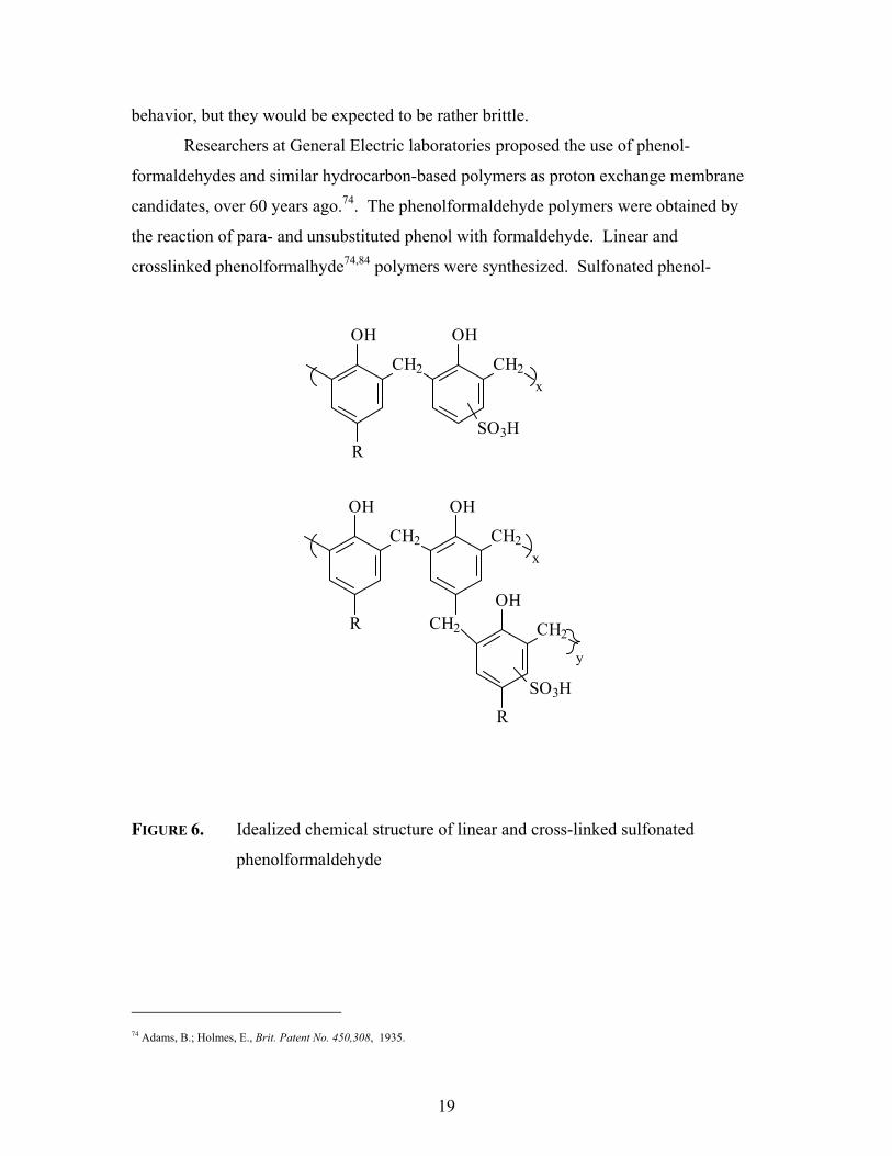
behavior, but they would be expected to be rather brittle.
Researchers at General Electric laboratories proposed the use of phenol-
formaldehydes and similar hydrocarbon-based polymers as proton exchange membrane
candidates, over 60 years ago.74. The phenolformaldehyde polymers were obtained by
the reaction of para- and unsubstituted phenol with formaldehyde. Linear and
crosslinked phenolformalhyde74,84 polymers were synthesized. Sulfonated phenol-
FIGURE 6. Idealized chemical structure of linear and cross-linked sulfonated
phenolformaldehyde
74 Adams, B.; Holmes, E., Brit. Patent No. 450,308, 1935.
OH
CH2 CH2
R
OH
SO3H
OH
CH2 CH2
R CH2
OH
OH
CH2
R
SO3H
x
x
y

20
formaldehyde membranes (Figure 6) demonstrated comparably poor performance as
polystyrene sulfonic acid 28. Acid catalyzed (by the pendent sulfonic acid groups)
hydrolysis was the suspected mode of degradation for the membranes, even though
oxidation of the benzylic units might seem more likely.
1.2.2 Perfluorinated Copolymers
Perfluorinated sulfonic acid copolymers are easily the most widely studied and
applied proton exchange membranes in proton exchange membrane fuel cell
investigations. The Teflon-like perfluorinated copolymers have demonstrated the most
superior properties of any aliphatic polymer examined75,76. Perfluorinated polymers are
well known for their exceptionally high chemical and thermal stabilities. Several studies
have confirmed the chemical stability of perfluorinated polymers in various conditions,
including strong bases, strong oxidizing and reducing agents5,8. These copolymers are
chemically stable against the oxidative conditions of a fuel cell due to the strong carbon-
fluorine bonds77, which are approximately 4 kcal stronger than aliphatic carbon-hydrogen
bonds78. The development of perfluorinated polymers increased confidence in the
application of proton exchange membrane fuel cells after the early failure using
sulfonated polystyrene11.
Nafion, produced and marketed by E.I. DuPont de Nemours, was developed for
space exploration applications79. These fully fluorinated electrolytes have been the focus
of several books and reviews in PEMFC literature80,81. The proposed structure of
Nafion is shown in Figure 7. Dow, Asahi Chemical and Aciplex have developed similar
fluoropolymers82. Dow marketed their perfluorinated copolymer under the name of Dow
XUS. Dow XUS was manufactured at 2 mil thickness (verses the original
75 Kordesch, K.; Simader, G., Fuel Cells and their Applications 1996, Wiley-VCH, p.72 76 Eisenberg, A.; Yeager, H. L. Perfluorinated Ionomer Membranes; ACS Symposium Series #180:, 1982. 77 Liebhafsky, H.A.; Cairns, E..J., Fuel Cells and Fuel Batteries, John Wiley and Sons, Inc., New York, 1968 78 Kerr, J.A., Chem. Rev 1966, 66, 465. 79 Steck, A., J. Power Sources1990, 29, 239. 80 Pourcelly, G.; Gavach, C. In Proton Conductors; Colomban, P., Ed.; Cambridge University Press: London, 1992; p 295. 81 Kerres, J.A., J. Membr. Sci. 2001, 185 (1), 3. 82 Wakizoe, M.; Velev, O.A.; Srinivasan, S. Electrochim. Acta 1995, 40, 335.

21
FIGURE 7. Proposed structure of Nafion and Dow XUS perfluorinated
copolymers20,85,86, respectively.
CF2CF2 CF CF2
O
CF2
CFF3C
O CF2CF2 SO3H
x y
z
CF2CF2 CF CF2
O
CF2
CF
SO3H
x y
2

22
thickness of Nafion at 7 mils) and had a lower equivalent weight, i.e., more pendent
sulfonic acid groups per -CF2 unit83. Nafion films are now produced at various
thicknesses, but mostly at about 1100 equivalent weights (~13 mole % comonomer). The
proposed structures are given in Figure 7. The thinner membrane and higher
concentration of proton exchange sites reportedly allowed Dow XUS to display better
performance in several aspects than Nafion.
Control of the equivalent weight in these polymers is managed by varying the
molar ratio of tetrafluoroethylene (x) and the specialty sulfonyl comonomer (y). By
varying this ratio, a wide range of copolymers with different equivalent weights (800-
1500) may be produced. Nafion 950 and Nafion 1100 are perhaps the most commonly
investigated membranes. These perfluorinated copolymers are melt processible in the
sulfonated fluoride form. Due to the associated high cost of the specialty co-monomers,
Dow XUS was more expensive than Nafion. A general drawback with all perfluorinated
proton exchange membranes is their cost71. The relatively high selling price is probably
related to the economics of producing the specialty perfluorosulfonic fluoride monomers,
and then converting to the sulfonic acid. Figure 7a displays the proposed synthesis of the
specialty monomers used for Nafion and Dow XUS84. Patent literature suggests that the
copolymerization synthesis of Nafion and other perfluorinated copolymers is actually
performed using the sulfonyl fluoride, which is then converted into its proton conductive
acid form prior to use85,86.
83 Srinivasan, S.; Velev, O.A.; Parthasarathy, A.; Manko, D.J.; Appleby, A.J., J. Power Sources 1991, 36, 299. 84 Steck, A.E.; Stone, C., in Proc. of 2nd Int. Symp. on New Mat. for Fuel Cell and Mod. Battery Sys. O. Savadogo and P.R. Roberge,
Eds., Montreal, Canada, 1997, 782. 85 Ezzell, B.R.; Carl, W.P.; Mod, W.A., US Patent 4,358,412, 1982. 86 Connollym, D.J.; Gresham, W.F., US Patent 3,282, 875 1966

23
FIGURE 7A. Proposed synthesis of perfluorinated comonomers utilized for Nafion
and Dow XUS copolymers71,84,85,86.
24
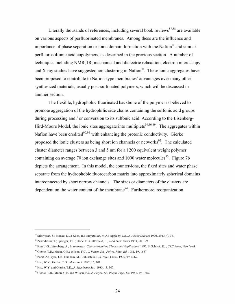
Literally thousands of references, including several book reviews87,88 are available
on various aspects of perfluorinated membranes. Among these are the influence and
importance of phase separation or ionic domain formation with the Nafion and similar
perfluorosulfonic acid copolymers, as described in the previous section. A number of
techniques including NMR, IR, mechanical and dielectric relaxation, electron microscopy
and X-ray studies have suggested ion clustering in Nafion®. These ionic aggregates have
been proposed to contribute to Nafion-type membranes’ advantages over many other
synthesized materials, usually post-sulfonated polymers, which will be discussed in
another section.
The flexible, hydrophobic fluorinated backbone of the polymer is believed to
promote aggregation of the hydrophilic side chains containing the sulfonic acid groups
during processing and / or conversion to its sulfonic acid. According to the Eisenberg-
Hird-Moore Model, the ionic sites aggregate into multiplets54,56,89. The aggregates within
Nafion have been credited90,91 with enhancing the protonic conductivity. Gierke
proposed the ionic clusters as being short ion channels or networks92. The calculated
cluster diameter ranges between 3 and 5 nm for a 1200 equivalent weight polymer
containing on average 70 ion exchange sites and 1000 water molecules93. Figure 7b
depicts the arrangement. In this model, the counter-ions, the fixed sites and water phase
separate from the hydrophobic fluorocarbon matrix into approximately spherical domains
interconnected by short narrow channels. The sizes or diameters of the clusters are
dependent on the water content of the membrane94. Furthermore, reorganization
87 Srinivasan, S.; Manko, D.J.; Koch, H.; Enayetullah, M.A.; Appleby, J.A., J. Power Sources 1990, 29 (3-4), 367. 88 Zawodinski, T.; Springer, T.E.; Uribe, F.; Gottesfield, S., Solid State Ionics 1993, 60, 199. 89 Kim, J.-S.; Eisenberg, A., In Ionomers: Characterization, Theory and Applications 1996, S. Schlick, Ed., CRC Press, New York. 90 Gierke, T.D.; Munn, G.E.; Wilson, F.C., J. Polym. Sci., Polym. Phys. Ed. 1981, 19, 1687 91 Porat, Z.; Fryer, J.R.; Huxham, M.; Rubinstein, I., J. Phys. Chem. 1995, 99, 4667. 92 Hsu, W.Y.; Geirke, T.D., Macromol. 1982, 15, 101. 93 Hsu, W.Y. and Gierke, T.D., J. Membrane Sci. 1983, 13, 307. 94 Gierke, T.D., Munn, G.E. and Wilson, F.C. J. Polym. Sci. Polym. Phys. Ed. 1981, 19, 1687.

25
FIGURE 7B. IONIC CLUSTER NETWORK MODEL FOR PERFLUOROSULFONIC ACID
COPOLYMER93.
occurred during hydration/dehydration cycles as suggested by a change in the number of
sulfonic acid groups as well as the number of clusters after the cycle (Figure 7c). More
recent publications95,96,97 suggest a more lamellar-like structure for the aggregates, but
still agree with their importance for the high proton conductivity in perfluorosulfonic acid
copolymers.
95 Kreuer, K.D., J. Membr. Sci. 2001, 185, 29. 96 Litt, M.H., Polym. Prepr. (Am. Chem. Soc., Div. Polym. Chem.) 1997, 38, 80. 97 Young ,S.K.; Trevino, S.F.; Beck-Tan, N.C., J. Polym. Sci. Part B: Polym. Phys 2002,40, 387.

26
FIGURE 7C. Redistribution of ionic sites/cluster during dehydration cycles94.
An additional important feature of Nafion-like membranes is the presence of
semi-crystallinity. The Nafion with equivalent weights of greater than 1000 possess
some crystalline domains originating from long tetrafluoroethylene sequences98. The
amount of crystallinity depended on the amount of specialty sulfonated comonomer
incorporated and decreased nearly completely at low (<1000) equivalent weights. Semi-
crystalline domains in these presumed random copolymers are associated with the good
water insolubility and relatively modest water swelling.
98 Starkweather Jr, H. W. Macromolecules 1982, 15, 320.

27
1.2.3 Post-Sulfonated Aromatic Engineering Thermoplastics
Generally, engineering thermoplastics are a broad class of polymeric materials
that produce tough, ductile films and are characterized by good thermal and mechanical
properties99. Their properties allow for diverse applications in the adhesive, films and
coatings, automotive, and electronic industries100. Engineering thermoplastics encompass
polymers such as polyarylates, poly (arylene ethers), polyimides, polyetherimides, and
others. The aromatic rings of these polymers make them easily modified for various
applications. One successfully demonstrated modification is sulfonation, via a variety of
sulfonating agents.
1.2.3.1 Poly (arylene ethers)
Poly (arylene ethers) are a class of high performance engineering thermoplastics
with high glass transition temperatures, high thermal stability, good mechanical
properties, and exceptional resistance to hydrolysis and oxidation101,102,103,104,105,106.
While there are many variations of poly(arylene ethers), the major branches of these
important materials are poly(ether sulfones) and poly(ether ketones). The general
structure of poly(arylene ethers) is given in Figure 8. The synthetic routes to these
materials will be discussed later.
99 Clagett, D.C. in Encyclopedia of Polymer Science and Engineering, H.F. Mark, N.M. Bikales, C.G. Overberger, G. Menges, Eds.,
Vol. 6, John Wiley and Sons, New York, 1986. 100 Odian., G., Principles of Polymerization, 3rd Edition, John Wiley and Sons, New York, 1991. 101 Cotter, R.J. Engineering Plastics: Handbook of Polyarylethers, Gordan and Breach Publishers: Basel, Switzerland, 1995. 102 Hedrick, J.L.; Labadie, J.W., Step-Growth Polymers for High Performance Materials: New Synthetic Methods, ACS Symp. Ser.
624, 1996. 103 Johnson, R.N. in Encyclopedia of Polymer Science and Technology, N.M. Bikales, Ed., John Wiley & Sons: New York, 1969. 104 Riley, D.J.; Gungor, A.; Srinivasan, S.; Sankarapandian, M.; Tchatchoua, C.; Muggli, M.W.; Ward, T.C.; McGrath, J.E.;
Kashiwagi, T., Polym. Eng. Sci 1997, 37, 1501. 105 Johnson, R.N.; Farnham, A.G., US Patent 4,175,175 1979. 106 Wang, S.; McGrath, J. E., in T. E. Long and M. Rogers Eds., Wiley and Sons, 2002, in press.

28
FIGURE 8. Generic representation of poly (arylene ethers)
(1) Poly(Arylene Ether Sulfones)
Perhaps the first sulfonation of a poly(arylene ether sulfone) was reported in the
patent literature by Quentin107. Chlorosulfonic acid was employed in an electrophilic
substitution reaction to introduce ionic groups along the commercially available polymer
known as Udel, marketed by Solvay Advanced Polymers(Figure 9). The room
temperature sulfonation reactions were conducted for different time intervals to yield
polymers with different levels of sulfonation.
FIGURE 9. Sulfonation of Udel Polysulfone112
107 (a) J.P. Quentin, Sulfonated Polyarylether Sulfones, US Patent 3,709,841, 1973.; (b) Brousse, C.L.; Cheapurlet, R.; Quentin, J.P.,
Desalinaton 1976, 18, 137.
O X O Yn
O
CH3
CH3
O S
O
O
O
CH3
CH3
O S
O
O
HO3S
ClSO3H-HCl

29
Many other researchers108,109,110,111 have tried to repeat this pioneering work. However,
chlorosulfonic acid causes undesirable and detrimental side reactions, such as chain
scission, branching and / or cross-linking at the isopropylidene group of the bisphenol A-
based polymers. Recently, several researchers used trimethylsilyl chlorosulfonate to
sulfonate Udel108,109. The silyl-protected reagent reportedly minimized chain scission,
etc., as determined by viscosity experiments.
Organosulfur reactions have been well studied for small molecules112. This
knowledge has translated into useful reactions on polymers. One such example of this
exchange of science is the use of sulfur trioxide (SO3) and sulfur trioxide complexes to
mildly sulfonate polymers. Sulfur trioxide is commonly used for the sulfonation of
molecules that decompose in strongly acidic media.112,113 Sulfur trioxide, due to three
oxygen atoms double-bonded to the sulfur, is a stronger sulfonation agent than
concentrated sulfuric acid and is reactive enough to sulfonate benzene directly, even at
temperatures as low as 0-10 oC112,114.
Noshay and Robeson115 utilized a sulfur trioxide and triethyl phosphate complex
(SO3-TEP) to sulfonate commercially available Udel, the industrially important bisphenol
A-based polysulfone. Coplan and Gotz demonstrated sulfonation of deactivated
poly(ether sulfone) using SO3116. Johnson et al. performed a comprehensive study on
functional membranes in the area of water desalination using SO3-TEP 117. They were
able to introduce different amounts of sulfonic acid groups along the polymer chain.
Moreover, Johnson found no evidence of a crosslinking side reaction using sulfur trioxide
108 R. Nolte, K. Ledjeff, M. Bauer, and R. Mulhaupt, J. Membr. Sci., 1993, 83, 211. 109 H.S. Chao and D.R. Kelsey, US Patent 4,625,000, 1986. 110 F. Lufrano, I.Gatto, P. Staiti, V. Antonucci, E. Passalacqua, Solid State Ionics, 2001, 145, 47. 111 Genova-Dimitrova, P.; Baradie, B.; Foscallo, D.; Poinsignon, C.; Sanchez, J.Y., J. Membr. Sci. 2001, 185, 59. 112 Cremlyn, R.J., An Introduction to Organosulfur Chemistry, John Wiley & Sons: New York, 1996. 113 Cerfontain, H., Mechanistic Aspects in Aromatic Sulfonation and Desulfonation, Part 1: Electrophilic Aromatic Sulfonation and
Related Reactions, Interscience, New York, 1967. 114 Cremlyn, R.J.; Bassin, P., Phosphorus, Sulfur, and Silicon, 1991, 56, 245. 115 Noshay, A.; Robeson, L. M. J. Of Appl. Poly. Sci. 1976, 20, 1885. 116 Coplan, M.J.; Gotz, G., US Patent 4,413,106, 1983. 117 Johnson, B. C.; Yilgor, I.; Tran, C.; Iqbal, M.; Wightman, J.; Lloyd, D.; McGrath, J. E. J. Polym. Sci. Polym. Chem. Ed. 1984, 22,
721.

30
as demonstrated by easy re-dissolution of the modified polymers. O’Gara et al.118 also
employed SO3-TEP for sulfonation of PES while exploring multiplet / cluster formations
using small angle x-ray spectroscopy (SAXS). Nolte and colleagues were likewise able
to generate similar sulfonated membranes, as well as water-soluble polymers, using
sulfur trioxide in chloroform (CHCl3)119. Furthermore, these researchers sacrificed some
of the sulfonic acid groups to introduce cross-links, after derivatization and reacting with
a diamine, to influence the swelling behavior of the hydrated films.
In a recent publication, Morley and Roberts adapted molecular modeling and the
related calculations to study the complex electrophilic substitution mechanism(s) by
sulfur trioxide120. Others113,121,122,123 have proposed various possible mechanisms or
intermediate species involved in the sulfonation of aromatic compounds via sulfur
trioxide, but it was experimentally not possible to properly characterize the
intermediates120 which are difficult to isolate. Figure 10 displays these suggested routes.
Experimental data have suggested the possible Wheland intermediates (5) and (6)121,122.
Rearrangement of (6) allows for the postulation of a toluene pyrosulfonic acid,
intermediate (7). The molecular modeling calculations favor (6). The toluenesulfonic
anhydride (9) is the main byproduct of the otherwise efficient substitution reaction.
A new sulfonation process for generating polysulfone ionomers has been
described by Kerres et al124,125,126. The procedure includes the cryogenic deprotonation of
the Udel poly(ether sulfone) using n-butyllitium, then reacting the lithiated polymer with
sulfur dioxide (SO2), and finally performing an oxidation/hydrolysis to yield the sulfonic
acid. The scheme is given in Figure 11. As shown, this procedure introduced the
118 O’Gara, J.F.; Williams, D.J.; MacKnight, W.J.; Karasz, F.E., J. Polym. Sci.Part B: Polym. Phys. 1987, 25, 1519, 119 Nolte, R.; Ledjeff, Bauer, M.; Mulhaupt, R., J Membr. Sci. 1993, 33, 211. 120 Morley, J.O.; Roberts, D.W., J. Org. Chem. 1997, 63, 7358. 121 Bosscher, J.K.; Cerfontain, H., Tetrahedron 1968, 24, 6543. 122 Lammertsma, K.; Cerfontain, H., J. Chem. Soc., Perkin Trans. 2, 1980, 2, 28. 123 Bosscher, J.K.; Cerfontain, H., J. Chem. Soc. Part B. 1968, 1524. 124 Kerres, J. ; Cui, W.; Reichle, S., J. Polym. Sci. Part A: Polym. Chem. 1996, 34, 2421. 125 Kerres, J.; Cui, W.; Eigenberger, G.; Bevers, D.; Schnumberger, W.; Fischer, A, Wendt, H., in Proc. of the 11th Hydrogen Conf.,
T.N. Veziroglu, C.J. Winter, J.P. Basalt, G. Kreysa, Eds., Stuttgart, Germany, 1996, p. 1951. 126 Kerres, J.; Zhang, W.; Cui, W., J. Polym. Sci. Part A: Polym. Chem. 1998, 36, 1441.
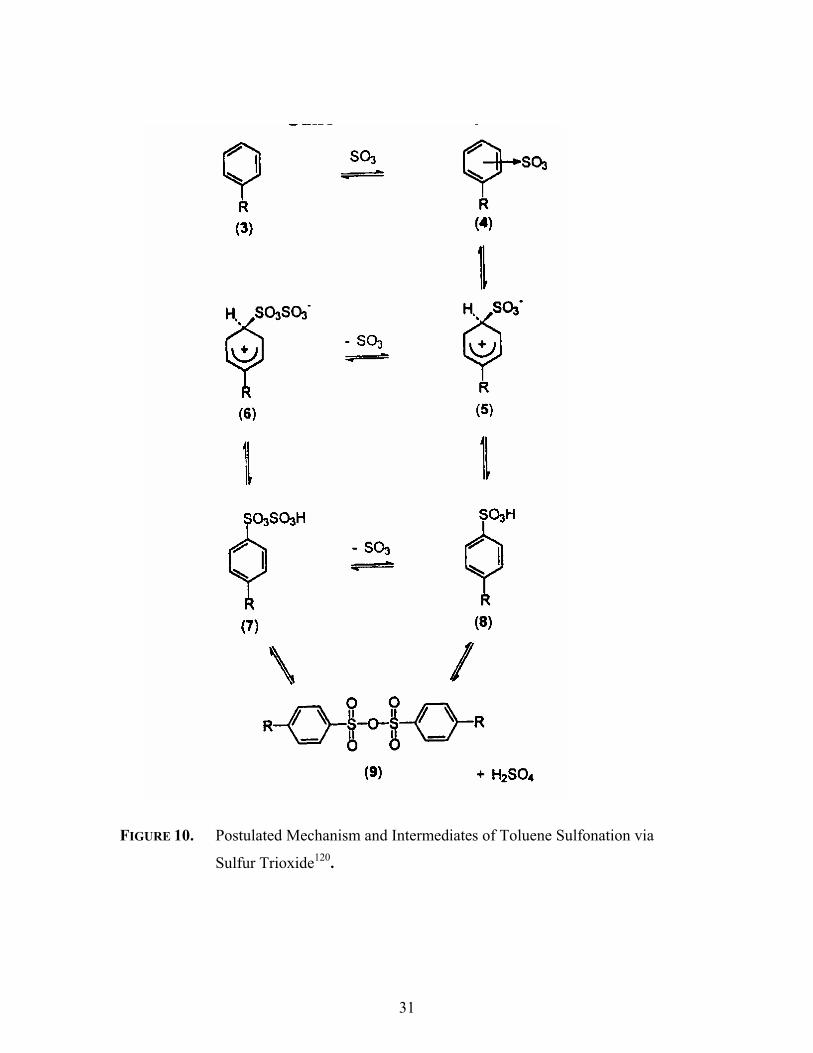
31
FIGURE 10. Postulated Mechanism and Intermediates of Toluene Sulfonation via
Sulfur Trioxide120.
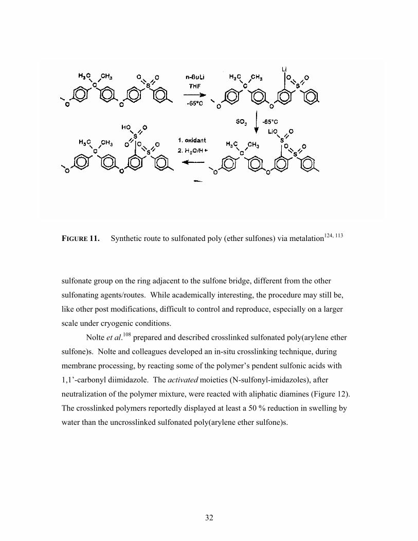
32
FIGURE 11. Synthetic route to sulfonated poly (ether sulfones) via metalation124, 113
sulfonate group on the ring adjacent to the sulfone bridge, different from the other
sulfonating agents/routes. While academically interesting, the procedure may still be,
like other post modifications, difficult to control and reproduce, especially on a larger
scale under cryogenic conditions.
Nolte et al.108 prepared and described crosslinked sulfonated poly(arylene ether
sulfone)s. Nolte and colleagues developed an in-situ crosslinking technique, during
membrane processing, by reacting some of the polymer’s pendent sulfonic acids with
1,1’-carbonyl diimidazole. The activated moieties (N-sulfonyl-imidazoles), after
neutralization of the polymer mixture, were reacted with aliphatic diamines (Figure 12).
The crosslinked polymers reportedly displayed at least a 50 % reduction in swelling by
water than the uncrosslinked sulfonated poly(arylene ether sulfone)s.

33
FIGURE 12. Crosslinking of sulfonated PAES using 1,1’-carbonyl diimidazole.108
(2) Poly(Arylene Ether Ketones)
Poly (arylene ether ketones) have been modified using various sulfonation agents.
Due to the semi-crystalline nature of certain poly (ether ketone)s and their corresponding
poor solubility in many solvents, sulfonations were first achieved in concentrated sulfuric
acid. The first investigation of sulfonated poly(ketone)s127 utilized this route. Other
researchers have increased the literature base for sulfonated poly(ether
ketones)128,129,130,131,132,133,134. Schneller et al. 132 proposed using SPEEK for proton
127 Lee, J.; Marvel, C.S., J. Polym. Sci.: Polym. Chem. Ed. 1984, 22, 295. 128 Bishop, M.T.; Karasz, F.E., Russo, P.S., Macromolecules 1985, 18, 86. 129 Bailly, C.; Williams, D.J.; Karasz, F.E.; MacKnight, W.J., Polymer 1987, 28, 1009. 130 Jin, X.; Bishop, M.T.; Ellis, T.S.; Karasz, F.E., Brit. Poly. J. 1985, 17, 4. 131 Devaux, J.; Delimov, D.; Daousti, D.; Legras, R.; Mercier, J.P.; Strazielle, C.; Nield, E., Polymer 1985, 26, 1994. 132 Schneller, A.; Ritter, H.; Ledjeff, K.; Nolte, R.; Thorwirth, R., EP 0574791 A2 1993. 133 Linkous, C.A.; Anderson, H.R.; Kopitzke, R.W.; Nelson, G.L., in Proc. of the 11th Hydrogen Conf., T.N. Veziroglu, C.J. Winter,
J.P. Basalt, G. Kreysa, Eds., Stuttgart, Germany, 1996, p. 559. 134 Peer, M., UK Patent Appl. GB 2217134 A 1989.
Polymer S OH
O
ON
N C NN
OPolymer S N
O
ON
+2
Polymer S O-
O
O
-CO2
H2N+ N
1,1'-carbonyl diimidazole Activated sulfonic acid
Polymer S N
O
ON
2 H2N R NH2+ Polymer S N
O
O
R N S Polymer
O
O
Crosslinked PolymerActivated sulfonic acid

34
exchange membranes. Using sulfuric acid, the influence of temperature, time, and water
content (i.e., concentration of acid used) have been investigated and optimum conditions
have been established135. However, one criticism of sulfonation using sulfuric acid to
sulfonate polymers is that the rate of polymer dissolution strongly influences the rate of
sulfonation. This dissolution while simultaneously sulfonating the polymer complicates
the process and restricts any homogeneity of the procedure. This directly leads to
difficulty in reproducibility in subsequent experiments or batches.
Chlorosulfonic acid has been successfully used to better control the degree of
sulfonation by varying the molar amount of chlorosulfonic acid used127,136. Recently,
Hamciuc et al.137 reported the sulfonation and chlorosulfonation of poly (ether ketone)s
containing hexafluoroisopropylidene groups (“6F”). Using 100% chlorosulfonic acid in
two hours, the authors reported the formation of the repeat unit shown in Figure 13. The
introduction of the 6F-moiety greatly decreased the chemical degradation experienced by
the bisphenol A based polyketones.
FIGURE 13. Chlorosulfonated hexafluoroisopropylidene containing poly (ether
ketone)137
A series of papers by Belgium researchers has been published on the sulfonation
of poly (ether ketone)s138,139,140. These scientists presented data consistent with first-
135 Bishop, M.T.; Karasz, F.E.; Ruso, P.S.; Langley, K.H., Macromolecules 1985, 18, 86. 136 Litter, M.I.; Marvell, C.S., J. Polym. Sci,: Polym. Chem. Ed1985, 23, 2205. 137 Hamciuc, C.; Bruma, M.; Klapper, M., J. Macromol. Sci.: Pure Appl. Chem. 2001, A38 (7), 659. 138 Daoust, D.; Devaux, J.; Godard, P., Polym Int. 2001, 50(8), 917.
O
CF3
CF3
O C
O
ClO2S

35
order kinetics with respect to the unsulfonated repeat units138, using 96% and 97%
concentrated sulfuric acid. Also, they noted a slowing effect on substitution of sulfonate
groups. This is reasonable if one considers the fact that sulfonate groups are electron
withdrawing. Interestingly, the researchers investigated the influence of the fluorine end-
groups on the mechanism and kinetics of sulfonation with concentrated sulfuric acid.
Noting that the sulfonation is a function of a number of variables (e.g., acid strength,
concentration of the polymer, generation of water as a by-product, temperature, time,
etc.)139, the authors concluded that the halide of the fluorine-terminated polymers does
have a surprisingly long-range (up to 3 repeat units) influence on the sulfonation.
1.2.4 Poly (Benzyl Sulfonic Acid) Siloxanes (PBSS)
A few researchers have proposed proton exchange membranes based on modified
alkoxy silanes141,142,143,144. Synthesized by the hydrolysis and condensation of benzyl-
triethoxyl silane precursors in a mixture of methanol, water, and triflic acid143,144, high
molecular weight polymers were reported. Figure 14 shows a representative structure.
FIGURE 14. Proposed chemical structure of poly (benzyl sulfonic acid) siloxane143.
139 Daoust, D.; Devaux, J.; Godard, P., Polym Int. 2001, 50(8), 925. 140 Daoust, D.; Devaux, J.; Godard, P., Polym Int. 2001, 50(8), 932. 141 Chanbouillet, Y.; Ravaine, D.; Armand, M.B.; Poinsignon, C., J. Non-Cryst. Solids 1988, 103, 325. 142 Schmidt, H.; Papall, M.; Rousseau, F.; Poinsignon, C.; Armand, M.B.; Sanchez, Y., Proceedings of 2nd Int. Symp. on Polymer
Electrolytes, B. Scrossati, Ed. , Elsevier, London, 1990, p. 325. 143 Ganthier-Luneau, J.; Denoyelle, A.; Sanchez, J.Y.; Poinsignon, C., Elecrochem. Acta 1992, 37, 1615. 144 Poinsignon, C., in 1st Int. Symp. on New Mat. for Fuel Cell Sys., Montreal, Canada, July 1995, poster No. 29.
S
OH
CH2
Si OO
O
OO
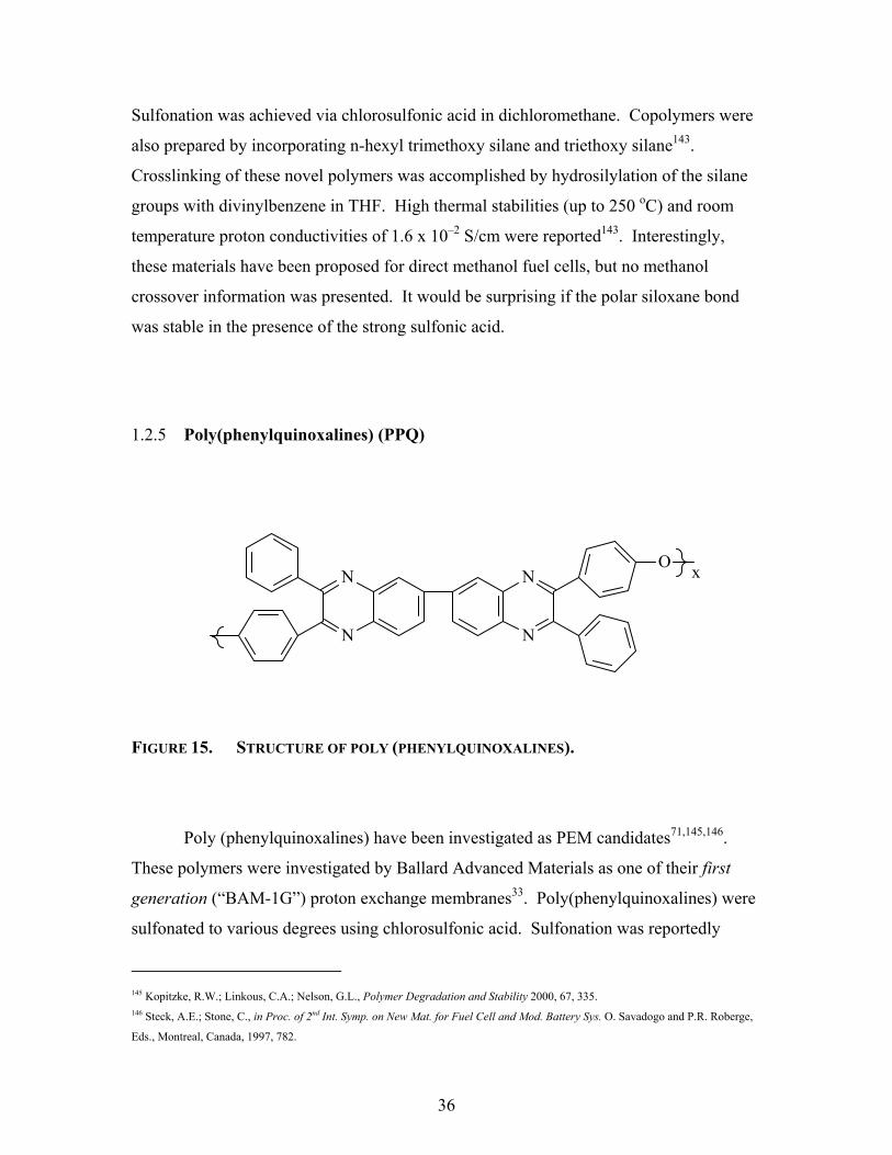
36
Sulfonation was achieved via chlorosulfonic acid in dichloromethane. Copolymers were
also prepared by incorporating n-hexyl trimethoxy silane and triethoxy silane143.
Crosslinking of these novel polymers was accomplished by hydrosilylation of the silane
groups with divinylbenzene in THF. High thermal stabilities (up to 250 oC) and room
temperature proton conductivities of 1.6 x 10⁻² S/cm were reported143. Interestingly,
these materials have been proposed for direct methanol fuel cells, but no methanol
crossover information was presented. It would be surprising if the polar siloxane bond
was stable in the presence of the strong sulfonic acid.
1.2.5 Poly(phenylquinoxalines) (PPQ)
FIGURE 15. STRUCTURE OF POLY (PHENYLQUINOXALINES).
Poly (phenylquinoxalines) have been investigated as PEM candidates71,145,146.
These polymers were investigated by Ballard Advanced Materials as one of their first
generation (“BAM-1G”) proton exchange membranes33. Poly(phenylquinoxalines) were
sulfonated to various degrees using chlorosulfonic acid. Sulfonation was reportedly
145 Kopitzke, R.W.; Linkous, C.A.; Nelson, G.L., Polymer Degradation and Stability 2000, 67, 335. 146 Steck, A.E.; Stone, C., in Proc. of 2nd Int. Symp. on New Mat. for Fuel Cell and Mod. Battery Sys. O. Savadogo and P.R. Roberge,
Eds., Montreal, Canada, 1997, 782.
N
N
N
N
O x

37
controllable from approximately 50 to well over 100 percent (i.e., greater than one
sulfonate group per repeat unit)146. While the initial performance in single cell-fuel cell
tests was good, sulfonated PPQ operated only 350 hours before failing146. Details on the
mode of failure were not disclosed.
1.2.6 Poly (Phenylene Oxide) (PPO)
Ballard Advanced Materials also investigated the sulfonated polymer resulting
from the polymerization of 2,6-diphenyl phenol (Figure 16)33,146. The acronym of P3O is
used to describe the unmodified polymer. The sulfonated P3O (P3OSO3H) was
accomplished by first brominating the polymer and then subsequently sulfonating it147.
These membranes had a maximum continuous running lifetime of 500-600 hours33,146
under Ballard’s single cell-fuel cell test conditions.
FIGURE 16. CHEMICAL STRUCTURE OF 2,6-DIPHENYL PHENOL
147 Hodgdon, R.B.; Hay, A.S., U.S. Patent 3,528,858, 1970.
OH

38
1.3 Direct, Step-Growth Polymerization of Sulfonated Monomers
A novel approach has been developed by several research groups to obtain
sulfonated aromatic copolymers-- the copolymerization of sulfonated monomers. The
direct copolymerization of a modified monomer is an insightful and different approach
than that of modification of a pre-formed polymer. Monomer modification allows
molecular-design control, to some degree, of the resulting copolymer. Numerous, subtle
sequence effects can be enhanced. Surprisingly, this synthetic route has only been
applied to high performance, condensation-type polymer (i.e., non-addition or
elastomeric polymers) systems within the last two decades. Primarily three distinct
systems have received the most attention in the literature: (1) polyimides; (2)
poly(arylene ethers), including sulfones, ketones, and phosphine oxides; and (3)
poly(sulfide sulfones). The following sections will explore the development of these
sulfonated copolymer membranes.
1.3.1 “Direct” Sulfonated Polyimides Copolymers
Polyimides, in general, are regarded as high performance materials possessing
high thermal stability and excellent mechanical properties148,149,150. Polyimides are rigid,
heterocyclic polymers that may be semi-crystalline, if flexible units or moieties are not
incorporated. Pendant side groups have also been introduced in various polyimides to
disrupt long-range packing order to minimize crystallinity151. Recently, several research
groups152,153,154 have incorporated sulfonic acid groups into polyimides, not for
148 Mittal, K.L. (ed) Polyimides: Synthesis, Characterization and Applications, 1&2. Plenum, NY, 1984. 149 Feger, C., Khojasteh, M.M., McGrath, J.E.(eds) Polyimides: Materials, Chemistry and Characterization. Elsevier, Amsterdam,
1989 150 Wilson, D., Stenzenberger, H.D., Hergenrother, P.M. (eds) Polyimides Blackie Glasgow, 1990;. 151 Ghosh, M.K., Mittal, K.L. (eds.) Polyimides: Fundamentals and Applications; Marcel Dekker: 1996. 152 Faure, S.; Cornet, G.; Mercier, R.; Pineri, M.; Sillion, B., in Proc. 2nd Int. Symp. New Mat. for Fuel Cell and Mod Battery Syst., O.
Savadogo and P.R. Roberge, Eds., Montreal, Canada, 1997, p.818. 153 Gunduz, N.; McGrath, J. E. Polymer Preprints 2000, 41(1), 180.

39
aforementioned crystallinity concerns, but for utility as proton exchange membranes for
fuel cells.
Pineri and collaborative French researchers152,155,156,157,158 described sulfonated
polyimides synthesized using commercially available monomers, including 4,4’-diamino-
2,2’-biphenyldisulfonic acid (BDSA), shown in Figure 17. These researchers
copolymerized this BDSA with 4,4’-oxydianiline, and either of two dianhydrides, 4,4’-
oxydiphthalic anhydride or 1,4,5,8-naphthalene tetracarboxylic dianhydride. The
copolymerization was employed to encourage solubility and to generate distinct
hydrophobic and hydrophilic segments along the copolymer.
Figure 17. Chemical structure of 4,4’-diamino-2,2’-biphenyldisulfonic acid (BDSA).
The dianhydride structure proved to have important effects on the life-time of the
polymers33. The 4,4’-oxydiphthalic anhydride yields traditional 5-membered
heterocyclic rings, while the naphthalene tetracarboxylic dianhydride produces 6-
membered heterocyclic rings. While the water uptake of both polymer series reportedly
remained constant at increasing temperatures, unlike the Nafion control, the phthalic
sulfonated polyimides failed before 100 hours of testing in a fuel cell. Failure of these
membranes due to hydrolysis of the sulfonated sequence was proposed as the degradation
site156. The sulfonated napthalic polyimides reportedly were stable for over 3000
154 Bernard, R. J.; Sherrington, D. C., in the 5th European Tech. Symp. Polyimides and High Performance Functional Polymers Proc.,
Montpellier, France, May 3-5, 1999. 155 Faure, S.; Mercier, R.; Aldbert, P.; Pineri, M.; Sillion, B., French Patent 96 05707, 1996. 156 Gebel, G.; Aldebert, P.; Pineri, M., Polymer 1993, 34, 333. 157 Genies, C.; Mercier, R.; Sillion, B.; Cornet, N.; Gebel, G.; Pineri, M., Polymer 2001, 42, 359. 158 Vallejo, E.; Pourcelly, G.; Gavach, C.; Mercier, R.; Pineri, M., J. Membr. Sci. 1999, 160, 127.
NH2H2N
SO3H
HO3S

40
hours159 at an unreported temperature. These results suggest that the six-membered
heterocyclic rings are more stable than the five-membered ring analogue, as suggested by
Rustanov and others160.
Gunduz and McGrath153,161,162 synthesized sulfonated polyimides using an
impressive variety novel sulfonated monomers and comonomers. These soluble
sulfonated copolymers were reportedly synthesized to high molecular weights, as based
on measured high intrinsic viscosities and the ability to cast tough ductile films. The
films were solution cast on glass substrates and the sulfonated polyimides were
characterized as thermally stable materials. Figure 18 displays the sulfonated monomers
these researchers investigated. Expected improved solubilities and membrane properties
justified the variances in the structures. A sample copolymerization is depicted in Figure
19. The highest protonic conductivity reported is about 0.02 S/cm, which compares
favorably to most of the aforementioned post-sulfonated polymers. Hong et al163
investigated similar directly sulfonated polyimide copolymers and has been able to
demonstrate high conductivities (e.g. 0.1 S/cm) in some cases. Hydrolytic stability at
80oC is still a major issue.
159 Faure, S.; Cornet, N.; Gebel, G.; Mercier, R.; Aldbert, P.; Pineri, M.; Sillion, B. in Proc. 2nd Int. Symp. on New Mater. for Fuel Cell
and Modern Battery Syst, Montreal Canada, 1997, p. 818. 160 Rusanov, A.L. and Bulycheva, E.G. Polyimides and Other High Temperature Polymers, Abadie, M.J.M. and Sillion, B. (eds.),
Elsevier, 1991, p. 125-149; (b) Mercier, R. French Patent; (c) Ponomarev, I.I., Nikol’skii, O.G., Volkova, Y.A., and Zakharov, A.V.,
Polymer Science, Ser. A, 1994, 36 (9), 1185. 161 Gunduz, N., SYNTHESIS AND CHARACTERIZATION OF SULFONATED POLYIMIDES AS PROTON EXCHANGE
MEMBRANES FOR FUEL CELLS , Ph.D. Thesis, VPI&SU, 2001. 162 Gunduz, N.; McGrath, J.E., Polymer Preprints 2000, 41(2), 1565. 163 Hong, Y. T.; Einsla, B.; Kim, Y.S.; McGrath, J. E., Polymer Preprints 2002, 43 (1), 666; (b) Hong, Y.T., et al. J. Polym. Sci., 2002,
in press.

41
1,4-Diaminobenzene sulfonic acid (pPDA-SO3H)
4,4’-diamino-2,2’-biphenyldisulfonic acid
3,3’-Disulfonated 4,4’-bis(3-aminophenoxy)phenyl sulfone (s-DADPS)163
FIGURE 18. Sulfonated diamines investigated by Gunduz, et al161.
O P OH2N NH2
O
SO3Na
O S OH2N
SO3Na
NH2
NaO3S
O
O
NH2H2N
SO3H
HO3S
NH2
H2N SO3H

42
FIGURE 19. Sulfonated polyimide copolymer based on BDSA153.
SO3H
NH2
HO3S
H2N
SO3 :
NH2
O3S
H2N
NH(Et)3
(Et)3HN :
OO
O
O
O
O
isoquinolinem-cresol200 oC, N23-4 hrs
Et3Nm-cresolR.T, N23-4 hrs
Sulfonated oligomer block
NH2H2Nm-cresol200 oC, N216hrs
NN
O
O
O
O
SO3(Et)3HN :
SO3 : NH(Et)3
NN
O
O
O
On m x
H+
NN
O
O
O
O
SO3H
SO3H
NN
O
O
O
On m x

43
Shobha et al. (Virginia Tech, unpublished results) reported the synthesis and
characterization of a new sulfonated monomer for application for proton exchange
membranes (Figure 20). No copolymers have yet been reported using this monomer.
FIGURE 20. Structure of novel phosphine oxide based sulfonated diamine.
P
O
O
SO3H
OH2N NH2

44
1.3.2 “Direct” Sulfonated Poly (Arylene Ether) Copolymers
Poly (arylene ethers) have been synthesized via a number of synthetic routes,
which will be reviewed in a later section. Nevertheless, sulfonated poly(ether sulfones),
poly(ether ketones), and poly(ether phosphine oxides) have been synthesized using
sulfonated comonomers. The following sections will survey these novel copolymers.
(1) Poly(arylene ether sulfones)
Perhaps the first reported synthesis of sulfonated poly(arylene ether sulfones) via
a pre-sulfonated monomer was reported by Ueda et al164. The disulfonated dihalide
monomer, sodium 5,5’-sulfonylbis(2-chlorobenzenesulfonate), was generated by reacting
4,4’-dichlorodiphenyl sulfone (DCDPS) with fuming sulfuric acid. This monomer will
herein be referred to as 3,3’-disulfonated 4,4’- dichlorodiphenyl sulfone (SDCDPS).
Figure 21 displays the Ueda et al. reaction procedure. This monomer, after
recrystallization, was copolymerized with bisphenol A and the unmodified 4,4’-
dichlorodiphenyl sulfone. The molar concentration of the sulfonated dihalide monomer
employed was reported up to 30 molar percent of any copolymer. Even though Ueda et
al.164 mention reverse osmosis hollow fibers in the introduction of their paper it is not
clear whether they ever proposed an actual application for their sulfonated copolymers. It
is noteworthy that Robeson and Matzner earlier synthesized SDCDPS and employed it as
an additive to improve the flame retardancy of polyesters165.
164 Ueda, M.; Toyota, H.; Ochi, T.; Sugiyama, J.; Yonetake, K.; Masuko, T.; Teramoto, T., J. Polym. Sci., Polym. Chem. Ed.,1993, 31,
85. 165 Robeson, L. M.; Matzner, M., US Pat. # 4380598 Flame Retardant Polyarylate Compositions to Union Carbide, April 19, 1983.

45
FIGURE 21. Synthesis of 3,3’-disulfonated 4,4’-dichlorodiphenyl sulfone164
However, Ueda’s copolymerization research has been expanded and reinvigorated
by McGrath et al166 and colleagues167 focusing on the development of proton exchange
membrane candidates for fuel cells. Members of the McGrath research group at Virginia
Tech have developed novel sulfonated poly(arylene ether sulfone) copolymers. First, the
synthesis of sulfonated dichlorodiphenyl sulfone was modified, resulting in higher
monomer yields168. Second, partially and wholly aromatic sulfonated poly (arylene
sulfone) copolymers were synthesized using several different bisphenols169,170. Third, the
copolymers employed higher molar concentrations (up to 100 mol percent) of SDCDPS.
It was demonstrated that a higher reaction temperature (~190 oC) was needed to achieve
very high molecular weight copolymers using the DCDPS/SDCDPS system.
Nonetheless, further research using more reactive 4,4’-difluorodiphenyl sulfone (DFDPS)
166 McGrath, J.E.; Formato, R.; Kovar, R.; Harrison, W.; Mecham, J.B., ACS Symposium March 1999. 167 Wang, F.; Hickner, M.; Ji, Q.; Harrison, W.; Mecham, J.B.; Zawodzinski, T.A.; McGrath, J.E., Macromol. Symp 2001, 175 (1),
387; (b) ibid, J Membr. Sci. 2002. 197, 231. 168 Wang, F.; Ji, Q.; Harrison, W.; Mecham, J.B.; Formato, R.; Dovar, R.; Osenar, P.; McGrath, J.E., PolymerPreprints 2000, 41 (1),
237. 169 (a) Harrison, W.; Shobha, H.; Wang, F.; Mecham, J.; Glass, T.; O’Connor, K.; McGrath, J.E., Polymer Preprints 2000, 41 (1),
1239; (b) Harrison, W.; Wang, F.; Hickner, M.; Kim, Y.S.; McGrath, J.E., Polymer Preprints2002, 43(1). 170 Harrison, W.; Wang, F.; Kim, Y-S.; Hickner, M.; McGrath, J.E., ACS Polymer Preprints 2002, 43 (1), 701; (b) ibid, J. Polym Sci.,
submitted 2002.
SO
OCl Cl + SO3/H2SO4
90 oC, 6 Hours
SO
OCl Cl
HO3S SO3H
SO
OCl Cl
NaO3S SO3Na
NaCl

46
and the synthesized 3,3’-disulfonated 4,4’-difluorodiphenyl sulfone (SDFDPS) was
shown to yield high molecular weight copolymers with a polymerization temperature of
~175 oC171.
Interestingly, functionalized oligomers have been reported by Mecham et
al172,173,174 from this same Virginia Tech research group. Meta-amino phenol was used as
a mono-functional endcapper with 4,4’-biphenol and SDCDPS. The synthesis of these
wholly aromatic, 100% sulfonated oligomers is presented in Figure 22. The molecular
weights of the amine-terminated sulfonated oligomers were controlled from 10,000 to
30,000 g/mol. Subsequent copolymerization of the functionalized oligomers with
different diamines and dianhydrides was employed to synthesize novel multiblock
polyimide-block-sulfonated poly(ether sulfone) copolymers173. This may have been the
first reported synthesis of such membranes for any application. Similar to earlier
described aliphatic triblock copolymer, like DAIS materials in Figure 4, these polymers
were designed to have well defined morphology and influence on the phase separation of
the hydrophilic [sulfonated poly(ether sulfone)] regions and the hydrophobic [polyimide]
regions, (see Figure 23). These membranes displayed high thermal stabilities.
Surprisingly, these membranes had very low water uptake (maximum 12% at any
composition), and hence, measured proton conductivities (0.03 S/cm maximum measured
value reported)173 were believed to suffer. Further clarification of this phenomenon is
required.
171 Wang, F.; Mecham, J.B.; Harrison, W.L.; McGrath, J.E., PolymerPreprints 2000, 41 (2), 1401. 172 Mecham, J.B.; Shobha, H.K.; Wang, F.; Harrison, W.L.; McGrath, J.E., ACS Polymer Preprints 200, 41(2), 247. 173 Mecham, J.B., Ph.D. Thesis, VPI & SU, December 2001. 174 Mecham, J.B.; Wang, F.; Glass, T.E.; Xu, J.; Wilkes, G.L.; McGrath, J.E., Polymeric Materials: Science and Engineering 2001, 84,
105.

47
FIGURE 22. Synthesis of amine-terminated sulfonated poly (arylene ether sulfone)
oligomers.173
HO OHHO
NH2
Cl S
O
O
Cl
SO3NaNaO3S
O
H2N
O OS
O
O
S
O
ONH2
O
NaO3S SO3Na NaO3S SO3Na
Biphenolm-aminophenol
x
s-DCDPS
NMP, Toluene
K2CO3
155 °C, 1h190 °C, 16 h

48
FIGURE 23. Synthesis of polyimide-block-sulfonated poly(arylene ether sulfone) 173
O
O
O
O
O S
O
O
O O
SO3NaH2N SO3Na
S
O
OSO3NaSO3Na
O
NH2n
H2N O NH2
O
O
O
O
(Polyimide)-(Polyarylene ether)
1) EtOH, NEt3 110°C, 30 minStrip off EtOH
2) NMP, o-Dichlorobenzene 165°C (internal temp) 6hr, 200°C 18 hr
3) Isolate with 100% 2-propanol, filter product
4) Dry under Vacuum, RT 3hr, 200°C 12hr
x y

49
(2) Poly(arylene ether ketones)
Similar direct copolymerization techniques for sulfonated poly(arylene ether
sulfone) copolymers were demonstrated by other researchers to synthesize a series of
sulfonated poly(arylene ether ketones)175,176,177,178. Using 3,3’-disulfonated 4,4’-
difluorodiphenyl ketone (Figure24), Wang et al. produced high molecular weight
copolymers with a bisphenol and the unsulfonated 4,4’-
difluorodiphenyl ketone. Figure 25 gives a typical polymerization scheme176.
FIGURE 24. Structure of 3,3’-disulfonated 4,4’-difluorodiphenyl ketone177.
Comparable to the sulfonated poly (arylene ether sulfone) copolymers, the sulfonated
poly (arylene ether ketone) copolymers were synthesized in high yields using appropriate
reaction conditions. The measured thermal stability was high for these polymers in air
and nitrogen. However, no proton conductivity values were reported since only the salt
form was examined and it was not the interest of the researchers. Interestingly, Gan et al.
synthesized similar sulfonated poly(arylene ether ketones) via Friedel-Crafts acylation
reactions of oligomers178.
175 Wang,F.; Chen, T.; Xu, J., Macromolecular Chem. and Phys1998, 199, 1421. 176 Wang,F.; Li, J.; Chen, T.; Xu, J., Polymer, 1999, 40, 795 177 Wang, F.; Qi, Y.H..; Chen, T.L.; Xing, Y.; Lin, Y.H.; Xu,J.P., Acta Crystallographica Section C-Crystal Structure Comm., 1999,
55, 871. 178 Gan, D.; Lu, S.; Wang, Z., Polym. Int. 2001, 50, 812.
CO
F F
NaO3S
SO3Na

50
FIGURE 25. Sulfonated poly (arylene ether ketone) copolymers via direct
polymerization. 176
Hexafluoroisopropylidene bisphenol A (6F Bisphenol A) was recently used to
polymerize more thermally stable amorphous sulfonated poly (ether ketone)s via direct
copolymerization as competitive candidates for PEMFCs179. The representative repeat
unit is given in Figure 23. High proton conductivities (up to 0.08 S/cm) were reported at
30 oC.
179 (a) Hopp, R.; Wang, F.; McGrath, F.E., 2001 Summer Undergraduate Research Program Reports, Virginia Tech, August 2001; (b)
Wang, F. et al. Electrochemical Society Proceedings, Philadelphia, PA., 2 002 .
CH3
CH3
n HO OH C
O
x Cl Cl c
O
Cl Cl
NaO3S SO3NaNMP, Toluene, K2CO3
150 oC, 5H190 oC, 15H
CH3
CH3
O O C O
O CH3
CH3
O CO
NaO3S SO3NaX 1-X

51
FIGURE 26. Structure of 6F-containing sulfonated poly (ether ketone) via direct
copolymerization179.
(3) Poly(arylene ether phosphine oxide)
Poly (arylene ether phosphine oxides) have been established as high performance
polymers and effective flame retardant materials180,181,182. Recently, 4,4’-
bis(fluorophenyl) phenyl phosphine oxide (BFPPO) was modified by fuming sulfuric
acid and purified to yield a mono-substituted sulfonated monomer183. Sulfonated BFPPO
(SBFPPO) was isolated from a mixture of starting material, and di- and tri-sulfonated
compounds. The latter compounds were the minor products. Figure 27 displays the
structure of SBFPPO.
FIGURE 27. Structure of sulfonated 4,4’-bis(phenyl) phenyl phosphine oxide183.
180 Hergenrother, P.M., Angew Chem. Int. Ed. Engl. 1990, 29, 34. 181 Smith, C.D.; Grubbs, H.J.; Webster, H.F.; Gungor, A.; Wightman, J.P.; McGrath, J.E., High Perfor. Polym. 1991, 4, 211. 182 Riley, D.J.; Gungor, A.; Srinivasan, S.A.; Sankarapandian, M.; Tchatchoua, C.; Muggli, M.W.; Ward, T.C.; McGrath, J.E., Polym
Eng. Sci. 1997, 37(9), 1501. 183 Shobha H.K., Smalley, G.R., Sankarapandian, M. and McGrath, J.E. ACS Polymer Preprints 2000, 41(1), 180
CF3
CF3
O O C O
O CF3
CF3
O CO
HO3S SO3HX
y
P
O
SO3- Na+
F F

52
Sulfonated, wholly aromatic copolymers were synthesized using various molar
ratios of SBFPPO and BFPPO, and 4,4’-biphenol. The polymers showed high thermal
stabilities and glass transition temperatures (Tgs). The measured proton conductivities
were lower than comparable directly polymerized poly(ether sulfone)s and poly(ether
ketone)s. This may be due to the fact that there are two proton exchange (sulfonic acid)
sites on the modified sulfone and ketone dihalide monomers verses only one on the
sulfonated 4,4’-bis(phenyl) phenyl phosphine oxide monomer. Also, a high degree of
hydrogen bonding between the pendent sulfonic acid and the phosphine oxide moiety was
observed which was believed to decrease the conductivity at 30 oC.
1.3.3 Poly(arylene sulfide sulfones) (PSS)
Sulfonated poly(sulfide sulfones) or poly (thioethers sulfones) were achieved via
direct polymerization of sulfonated difluorodiphenyl sulfone (SDFDPS) and a
synthesized thiobisphenol184. 4,4’-Dimercaptodiphenylsulfone (DMDPS) was
synthesized by the nucleophilic aromatic substitution reaction of sodium hydrosulfide
with 4,4’-dichlorodiphenylsulfone185. This monomer synthesis is hampered by the
impurities in the sodium hydrosulfide (available at a maximum purity of ~75%). The
major impurity is water as the sodium hydrosulfide is a hydrate. Product yields as high
as 60% were reported in the synthesis of the DMDPS monomer.
Sulfonated copolymers were produced using polymerization conditions similar to
those used to produce the sulfonated poly(arylene ether) copolymers. The polymers
showed high thermal stability, in both the acid and sodium-salt form. Figure 28 displays
the repeat unit and the reported intrinsic viscosity after two sulfonated copolymers, in
their free-acid forms, had been heated at various temperatures. Overall, no significant
change in intrinsic viscosities was noted even after the sulfonated copolymers had been
exposed to temperatures up to 220 oC.
184 Wang, F.; Mecham, J. B.; Harrison, W.; McGrath, J. E. Polymer Preprints 2000, 40, 180; Wiles, K., et al, Polymer Preprints, 2002,
42. 185 Liu, Y. Ph.D. Thesis, VPI & SU, 1999.
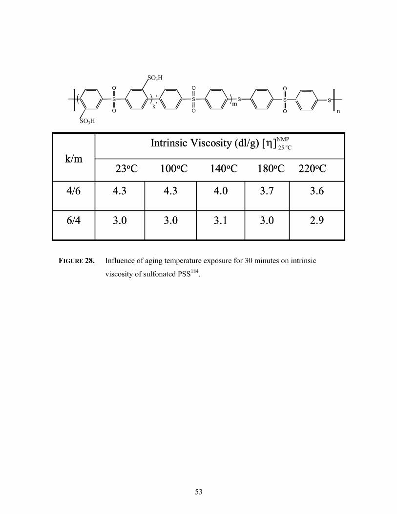
53
FIGURE 28. Influence of aging temperature exposure for 30 minutes on intrinsic
viscosity of sulfonated PSS184.
2.93.03.13.03.06/4
3.63.74.04.34.34/6
23oC 100oC 140oC 180oC 220oC
Intrinsic Viscosity (dl/g) [η]NMP
k/m
2.93.03.13.03.06/4
3.63.74.04.34.34/6
23oC 100oC 140oC 180oC 220oC
Intrinsic Viscosity (dl/g) [η] 25 oC
k/m
S
O
O
S
O
O
S SS
O
O
SO3H
SO3H
kn
m

54
1.4 Miscellaneous Blends and Nanocomposites
Recently, several researchers have investigated additives for sulfonated
copolymers to improve proton conductivity, as well as membrane properties. This
section will highlight some of these developing proton exchange membrane composite
candidates.
1.4.1 Polymer Blends
Physical polymer blending has been a long-standing, yet simple tool to modify the
properties of polymeric materials186,187. Several book reviews describe various aspects of
the preparation of polymer blends188,189. However, it is well known that many polymers
do not blend well. Micro- and macroscopic phase separation has been observed in many
polymer systems in the absence of polymer-polymer interaction or adhesion190.
Nevertheless, physical blending can alter certain properties. In the field of proton
exchange membranes, polymer blending, in general, has been investigated to improve or
modify properties such as mechanical strength, water swelling behavior, methanol
permeability, and proton conductivity.
Several research groups have investigated sulfonated poly(arylene ether) blends
with different engineering plastics in many variations; sulfonated poly(ether sulfones)
with poly(ether sulfones), sulfonated poly(ether sulfones) with poly(ether ketones)191,
sulfonated poly(ether ketones) with poly(ether sulfones),192,193 and sulfonated poly
186 Paul, D. R.; Newman, S., Eds. Polymer Blends; Academic Press: New York, 1978. 187 Noshay, A.; McGrath, J. E. Block Copolymers: Overview and Critical Survey; Academic Press: New York, 1977. 188 Paul, D.R.; Bucknall, C., Polymer Blends Vol.I. Formulation, Formulation, V. II, Performance John Wiley & Sons: New York,
2000. 189 Katime, I.A.; Iturbe, C.C., in Polymeric Materials Encyclopedia, J.C. Salamon, Ed., CRD Press, New York, 1996. 190 Olabisi, O.; Robeson, L. M.; Shaw, M. T. Polymer-Polymer Miscibility; Academic Press: New York, 1979. 191 van Zyl, A.J.; Kerres, J.A.; Cui, W.; Junginger, M., J. Membr. Sci. 1997, 137, 173. 192 Wilhelm, F.G.; Punt, I.G.M.; van der Vegt, N.F.A.; Strathmann, H.; Wessling, M., J. Membr. Sci 2001, 5138, 1. 193 Bowen, W.R.; Doneva, T.A.; Yin, H.B., J Membr. Sci. 2001, 181, 253.

55
(arylene ethers) with basic polymers like poly(benzimidazoles)194,195,196,197,198 is just a
partial list of reported blends for PEMFC applications. The logic for these experiments
lay in the reasonable belief that the unmodified polymer acts as a structural support and
decreases the swelling of the blended sulfonated polymer, which primarily functions as
the ion exchange material199.
An important commercially available composite proton exchange membrane
system was developed by W.L. Gore and Associates33. Marketed under the trade name of
Gore-Select, sulfonated perfluorinated polymers are supported on woven
polytetrafluorethylene (PTFE or Teflon). Similar supported membranes have been
applied in other industries200,201.
Several researchers202,203,204,205 have investigated the micro-reinforced Gore-
Select product. The films are characterized as translucent with good thermal, chemical
and dimensional stability. However, preliminary results202 showed the same water uptake
and lower ionic conductivities than Nafion of the same equivalent weights. One
advantage of the reinforced membranes is the fact that the thickness of the proton
exchange membrane can be decreased and still possess sufficient mechanical strength33
for fuel cell applications. Indeed, 12µm Gore Select PEM films with higher equivalent
weight (900) were evaluated and demonstrated good proton conductances, but the
reported values were still lower than the control material202.
194 Jorissen, L.; Gogel, V.; Kerres, J.; Garche, J., J. Power Sources 2001, 2578, 1. 195 Kerres, J.; Ullrich, A., Meier, F.; Haring, T., Solid State Iionics 1999, 125, 243. 196 Kerres, J.; Ullrich, A., Meier, F.; Haring, T.; Baldauf, M.; Gebhardt, U.; Preidel, W., J. New Mater. Eleclrochem. Soc. 2000, 3, 229. 197 Mikhailenko, S.D.; Zaidi, S.M.J.; Kaliaguine, S., J. Polym. Sci.: Part B, Polym. Phys., 2000, 38(1), 1386. 198 Deimede, V.; Voyiatzis, G.A.; Kallitsis, J.K.; Qingfeng, L.; Bjerrum, N.J., Macromolecules 2000, 33, 7609. 199 Werbrugge, M.W.; Hill, R.F.; Schneider, E.W., J. Am. Inst. Chem. Eng. 1992, 38, 93. 200 Taylor, E.J.; Paxienza, C.; Waterhouse, R.; Wilernski, G., in The Electrochem. Soc. Ext. Abst. , Oct. 1986, Vol. 86-2(590), p.883. 201 Pletcher, D.; Walsh, F.C.,, Eds., in Industrial Electrochemistry, Chapman and Hall, New York, 1990, p.179. 202 Kolde, J.A.; Bahar, B.; Wilson, M.S.; Zawodzinski, T.A.; Gottesfeld, S., in Proc. 1st Int. Symp. on Proton Conducting Membranes
Fuel Cells, S. Gcttesfeld, G. Halpert, and A. Landgrebe, Eds., 1995, p. 193. 203 Bahar, B.; Hobson, A.R.; Kolde, J.A.; Zuckerbrod, D., US Patent 5,547,551 , 1996. 204 Rusch, G.; Bahar, B., in Power of Electrochemistry 10th International Forum, Clearwater, 1996. 205 Velev, O.; Tran, D., Srinivassan, S., Appleby, A.J.; Dhar, H.P., in The Electrochem. Soc. Ext. Abst. May 1996, Abst No. 29.

56
1.4.2 Additives and Dopants
As discussed in an earlier section, operation of proton exchange membrane fuel
cells at temperatures above 100 oC is advantageous in several ways, including the
generally expected improved fuel cell efficiency. However, perfluorinated polymers
perform poorly at temperatures above 80 oC, due mainly to anticipated dehydration.
Furthermore, the boiling of water at temperatures above 100 oC, except under pressure,
compounds difficulties in the development of functioning high temperature PEMFC.
Much research, within the last decade or so, has been undertaken to find components
and/or systems that allow higher temperature operation. The field of nanocomposite
proton exchange membranes has developed out of these efforts.
Heteropolyacids (HPAs) are highly conductive in the crystalline form206.
Accordingly, HPAs have been blended into various polymers in the search for new
PEMs207,206,208,209,210. Several heteropolyacids, including phosphotungstic acid,
silicotungstic acid, zirconium phosphate, phosphomolybdic acid, etc., have been
investigated. Higher proton conductivities were reported for these composite
membranes. Kim et al207 reported proton conductivity values of ~0.15 S/cm at 140 oC at
100% relative humidity, under pressure for developmental directly sulfonated poly(ether
sulfone) copolymers containing 30 weight percent of very well dispersed phosphotungstic
acid. The HPA is suggested to provide an alternative mechanism for proton conductivity
in low water environments. Unpublished data for an unsulfonated, partially fluorinated
poly(arylene ether nitrile) containing 50 weight percent phosphotungstic acid
demonstrated a proton conductivity of 0.05 S/cm at room temperature,211 which is
expected to increase at elevated temperatures. The heteropolyacid was proposed to be
well dispersed via an association with the polar nitrile group of the host polymer matrix
206 Zaidi, S.M.J.; Mikhailenko, S.D.; Robertson, G.P.; Guiver, M.D.; Kaliaguine, S.J., J. Membr. Sci. 2000, 173, 17. 207 Kim, Y-.S.; Wang, F.; Hickner, M.; Zawodzinski, T.A.; McGrath, J.E., ACS Polym Mat: Sci. Eng. Preprints 2001, 85; ibid J.
Membr. Sci., accepted Nov 2002. 208 Malhotra, S.; Datta, R., J. Electrochem. Soc.,1997, 144, L23. 209 Tazi, B.; Savadogo, O., in Proc. 2nd Int. Symp. New Mat. for Fuel Cell and Modern Battery Syst., O. Savadogo and PR. Roberge,
Eds., Montreal, July 1997, p.864. 210 Costamagna, P.; Yang, C.; Bocarsly, A.B.; Srinivasan, S., Electrochim. Acta 2002, 47, 1023. 211 Harrison, W.; Sumner, M.; Kim, Y.-S.; Riffle, J.S; McGrath, J.E., Group Meeting Discussion, March 2002 .

57
since the films were transparent. This association was investigated by FTIR, which
demonstrated shifts (in wave numbers) of the nitrile group and tungsten-oxygen bond of
the HPA. Ductile composite membranes were observed, even with the high weight
fraction of phosphotungstic acid, but further investigations, such as the long-term
stability of these composites, are needed.
Composite membranes based on zirconium hydrogen phosphonates210,212,213,
zeolites214, silica215,216 and other components217,218 have been investigated with
improvements reported in many properties relative to their matrix materials. As one
example of improved membrane behavior, Nafion filled with cesium ions displayed
reduced methanol crossover219. Silica-Nafion composites allowed direct methanol fuel
cell operation at 145 oC due to higher initial water uptake215. Recently, boron phosphate
was reported to have increased the proton conductivity of post-sulfonated PEEK220.
Liquid phosphoric acid-doped membranes have also been investigated for non-
aqueous PEMFC systems221,222,223,224,225. Doped polybenzimidazoles have received the
most attention. Doping levels of up to six molecules of H3PO4 per repeat unit were
achieved222, and depending on doping technique, film thickness, etc., proton
conductivities of 0.01-0.04 S/cm were reported. Some basic concerns, such as acid
leaching, will need to be addressed before there is widespread application of these
systems is realized. It is also notable that Ballard Advanced Materials’ first generation
212 Hamlen, R.P., US Patent 5,849,428 , 1998. 213 Yang, C.; Costamagna, P.; Srinivasan, S.; Benziger, J.; Bocarsly, A.B., J. Power Sources 2001, 103(1), 1. 214 Poltarzewski, Z.; Wieczorek, W.; Przyluski, J.; Antonucci, V., Solid State Ionics 1999, 119, 301. 215 Antonucci, P.L.; Arico, A.S.; Creti, P.; Ramunni, E.; Antonucci, V., Solid State Ionics 1999, 125, 431. 216 Watanabe, M.; Uchida, H.; Seki, Y.; Emori, M.; Stonehart, P., J. Electrochem. Soc. 1996, 143, 3847. 217 Kjaer, J.; Yde-Andersen, S.; Knudsen, N.A.; Skou, E., Solid State Ionics 1991, 46, 169. 218 Rao, N.; Andersen, T.P.; Ge, P., Solid State Ionics 1994, 72, 334. 219 Tricoli, V., J. Electrochem. Soc. 1998, 145, 3798. 220 Mikhailenko, S.D.; Zaidi, S.M.J.; Kaliaguine, S., Catalysis Today 2001, 67(1-3), 225. 221 Wang, T.J.; Wasmus, S.; Savinell, R.F., J. Electrochem. Soc. 1996, 143, 1233. 222 Samms, S.R.; Wasmus, S.; Savinell, R.F., J. Electrochem. Soc 1996, 143, 1225. 223 Ren, X.; Wilson, M.S.; Gottesfeld, S., J. Electrochem. Soc 1996, 143, L12. 224 Ren, X.; Wilson, M.S.; Gottesfeld, S., in Proc. 1st Int. Symp. Proton Conduction Membrane Fuel Cells, S. Gottesfeld, G. Halpert,
and A. Landgrebe, Eds., 1995, 95-23, p. 252. 225 Wainright, J.S.; Wang, J.T.; Weng, D.; Savinell, R.S.; Litt, M., J. Electrochem. Soc. 1995, 141, L121.
58
membranes (BAM1G) were based on somewhat related sulfonated polybenzimidazoles,
which only lasted about 350 hours before failure146.
A number of papers have focused on the doping of polyethylene oxides (PEO).
For example, a PEO + NH4ClO4 system gave a reported conductivity up to 5 x 10⁻⁵
S/cm226. This same research group reported a similar system using PEO and NH4I that
gave a conductivity of about the same value227. The doping of an ethylene oxide-
propylene oxide copolymer with an alkali metal salt has been described228. This system
had a room temperature conductivity of 10–5, but improved conductivity at 100 oC (10 –3).
Compared to Nafion, these systems are too resistive (low proton conduction) to be useful
for power generation.
As seen by this survey, inexhaustive amounts of literature available are covering
different aspects of fuel cell development, other than membrane performance.
226 Hashmi, S.A.; Kumar, A.; Maurya, K.K.; Chandra, S., J. Phys. D: Appl. Phys., 1990, 23, 1307. 227 Maurya, K.K.; Srivastava, N.; Hashmi, S.A.; Chandra, S., J Phys. D: Appl. Phys., 1992, 27, 6357. 228 Florjanczyk, A.Z.; Kraweic, W.; Wieczorek, W.; Siekierski, M.. J Polym. Sci. Polym. Phys. Ed. 1995, 33, 629.

59
II. LITERATURE REVIEW: POLY (ARYLENE ETHER) SYNTHESIS
Since the main focus of this dissertation is on the synthesis of poly(arylene ether
sulfone) copolymers, a discussion of the synthetic routes to poly(arylene ethers) will be
presented here.
1.5 The Ullman Reaction
Poly (arylene ethers) have been synthesized from unactivated halides using the
Ullman reaction229,230,231232,233. Ullman-type reactions have been well studied for small
molecules. They involve the reaction of a phenol, in the presence of a copper catalyst,
with an aromatic halide. This synthetic route to aromatic polyethers has been worked
with non-activated aromatic halides; this reality allows for utility of monomers to
produce poly(arylene ethers) not possible by usual activated nucleophilic aromatic
substitution mechanisms234. The general synthetic approach is given in Figure 29.
Dibromo-monomers were most reactive via this approach since breaking the aryl halide
bond is the rate determining step. In fact, the halide reactivity was I > Br > Cl >> F.
Early research produced only low molecular weight products. Stamatoff235,236
was possibly the first to report high molecular weight polymers using a modified Ullman
procedure. He successfully condensed p-bromo-sodium phenolate using cuprous chloride
and an organic base as cocatalyst. To yield high molecular weight polymers it was
demonstrated that a dry, oxygen- free polymerization system must be maintained along
with high temperatures, using nitrobenzene, benzophenone, etc. as solvents. Non-linear
229 Farnham, A.G.; Johnson, R.N., US Patent 3,332, 909 , 1967. 230 Jurek, M.J., McGrath, J.E., ACS Polymer Preprints 1987, 28(1), 180. 231 Jurek, M.J., Ph.D. Thesis, VPI &SU, 1987. 232 Farnham, A.G.; Robeson, L.M.; McGrath, J.E., J. Appl. Polym. Sci. Poly. Symp. 1975, 26, 373. 233 Jennings, B.E.; Jones, M.E.B.; Rose, J.B., J. Polym. Sci.: Part C 1967, 16, 715, 234 S. Wang and J. E. McGrath, “ Polyarylene Ethers”: A Review, in M. Rogers and T.E. Long, eds., Step Polymerization, Wiley,
2002 235 (a) Stamatoff, G.S., French Patent 1,301,174 , 1962, (b) Stamatoff, G.S., US Patent 3,228,910 , 1966. 236 Stamatoff, G.S., Chem Abstracts 66, 56009q.

60
and/or crosslinked polymers were produced when even trace amounts of oxygen were
present in the system. Oxygen promoted a free radical side reaction leading to the
branched polymers237.
Benzophenone solvent with a cuprous chloride-pyridine complex as the catalyst is
a better polymerization system238. The resulting polymers demonstrated thermal stability
ad low dielectric constants of interest to microelectronics. Unfortunately, the Ullman
reaction approach has been characterized by poor reproducibility, the need for specialty
brominated monomers, and the difficulty of removing copper salts.234
FIGURE 29. Ullman synthesis of poly (arylene ethers)229.
237 Pankova, E.S.; Martsenitsena, S.V.; Derlin, A.A., Vysokomol Soyed A, 1975, 17(7), 1415. 238 Burgoyne, W.; Robeson, L. M. US Patent 5,658,994, 1997.
Na+ -O X O-Na+ + Br Y Br
5-10 mol% Cu2ODMSO, 153 oC
O X O Y + 2 NaBr
where X and Y = aromatic groups

61
1.6 Nickel Coupling Reaction
Perhaps, the newest approach for preparing poly(arylene ethers) is via nickel
coupling reactions. Ni0 is used in the formation of aromatic carbon-carbon bonds239.
Also, nickel coupling reactions can utilize more commonly available chlorinated
monomers, in contrast to brominated compounds needed for Ullman-type reactions.
Aprotic solvents are used as the reaction media at the relatively low polymerization
temperatures of 60 to 80 oC240,241. Interestingly, activated dihalide as well as
nonactivated dihalide monomers may be polymerized. Ghassemi et al.242 reported the
synthesis of aromatic phosphine oxide containing polymers via nickel coupling reactions.
1.7 Friedel-Crafts Electrophilic Substitution
A third synthetic route to poly(arylene ethers), in particular poly(arylene ether
sulfones), is via Friedel-Crafts electrophilic substitution243,244. The sulfone linkages are
formed by the reaction of aryl sulfonyl chlorides with aromatic compounds. Using this
mechanism, poly(arylene ether sulfones) can be synthesized in solvents such as dimethyl
sulfone, chlorinated biphenyl and nitrobenzene, or in the melt. The primary byproduct
for these polymerizations is HCl.
The sulfonylation mechanism has been reviewed112,245 and involves two steps.
The first step is the formation of the sulfonylium cation ArSO2+ resulting from the action
of the Lewis-acid catalyst on the sulfonyl halide (Figure 30). The second step is the
electrophilic cation attack on the aromatic carbon to generate an intermediate complex
followed by the elimination of a proton yielding the new sulfone linkage. It is important
that the aromatic ring being attacked not contain electron withdrawing groups, such as -
239 Colon, I.; Kwiatokowski, G.T., J. Polym. Sci., Polym. Chem. 1990, 28, 367. 240 Colon, I.; Maresca, L. M.; Kwiatkowski, G. T. U S Patent 4, 263 466 , 1991 241 Havelka, P. A.; Shearea, V. V. Macromolecules 1999, 32, 6418. 242 Ghassemi, H.; McGrath, J.E., Polymer 1997, 38, 3139; (b) idid, Polymer Preprints 2003, 43(1). 243 Ivin, K.J.; Rose, J.B., Advances in Macromolecular Chemistry, W.M. Pasika, Ed., Academic Press, London, Vol. 1, 336, 1968. 244 J.B. Rose, Polymer 1974, 15, 456.

62
SO2- or –CO-, for facile reaction with the electron-deficient sulfonylium cation. Several
catalysts, such as AlCl3, AlBr3, FeCl3, SbCl5, BF3, etc., have been utilized in Friedel-
Crafts reactions114,112,251,246.
High catalyst concentrations were employed in the early electrophilic aromatic
substitution syntheses of polysulfones. It was realized that if high temperatures (120 to
250 oC) were used, especially in melt reactions, lower concentrations (0.1 to 4 wt%
FeCl3) of Lewis acids could be used247,248. However, variations in polymer structure have
been noted due to sulfonylation on various positions on the arylene-ring249. Furthermore,
bulk polymerizations via Friedel-Craft mechanisms commonly resulted in branched or
crosslinked material, as evident by polymer insolubility.
Polymers made via Friedel-Craft sulfonylation mechanism were made in solution
at temperatures of ~120 oC250. The products were, in general, soluble high molecular
weight poly(arylene sulfones). Not surprisingly, electron-donating groups enhance the
sulfonylation process. Moreover, the polymerization of relatively deactivated monomers,
like benzophenone (Figure 31), was slow and some branching was suspected252.
245 Suter, C.M.; in The Organic Chemistry of Sulfur, New York, 1944, p.670. 246 Cox, S.F.; Neill, K.G., Australian Patent 242,187 , 1962. in Chem Abstracts 1965, 63, 4208g. 247 Jones, M.E.B, British Patent 979,111, 1965, in Chem. Abstracts 1965, 62, 9065h. 248 Jennings, B. E.; Jones, M. E. B.; Rose, J. B. J. Polym. Sci., Part C 1967, 16, 715. 249 Cohen, S.M.; Young, R.H., J. Polym. Sci., Polym. Chem. Ed. 1966, 4, 722. 250 Cudby, M. E. A.; Feasey, R. G.; Jennings, B. E.; Jones, M. E. B.; Rose, J. B. Polymer 1965, 6, 589.

63
FIGURE 30. Generation of sulfonylium cation251.
251 Olah, G.A., in Friedel-Crafts Chemistry, Wiley, New York, 1973, p. 488.
Cl S ArO
O
+ AlCl3 SO
OCl Ar
Cl3AlSO
Cl ArOCl3Al
SO
OCl Ar
Cl3AlAlCl4 + S Ar
O
O

64
FIGURE 31. Synthesis of poly (arylene ether sulfones) via Electrophilic Substitution.252
252 Jennings, B.E.; Jones, M.E.B.; Rose, J.B., J. Polym. Sci.: Part C 1967, 16, 715.
O
SCl O S ClO
O
O
O
C
O
SCl O S ClO
O
O
O
O SSO
O
O
O
S O SO
O
O
OO
C
O
S O SO
O
O
O
SS ClClO
O
O
O+
+
+
Cat.
Cat.
Cat.

65
1.8 Nucleophilic Aromatic Substitution
Poly (arylene ethers) are now most commonly synthesized via nucleophilic
aromatic substitution mechanisms101,253,254,255,256. Nucleophilic aromatic substitution
(SNAr) reactions, in the synthesis of polymers, have been the focus of some good
reviews99,234, 257,258. Many important polymers are synthesized via the SNAr
mechanism259.
The important nucleophilic aromatic substitution mechanism utilized activated
halide monomers. The need for activating groups has been well established. The
nucleophilic aromatic substitutions on simple aromatic halides require high temperatures
because they are not very reactive260,261. For example, the nucleophilic aromatic
substitution of chlorobenzene with a hydroxide ion is given in Figure 32.
FIGURE 32. Nucleophilic aromatic substitution of chlorobenzene262.
The low reactivity of chlorobenzene can be explained by resonance structures. Four
different resonance structures can be drawn, including three of which that have a double
bond between the positive chlorine and the negative ring. The implied double bond
253 Hedrick, J. C.; Labadie, J. W., Macromolecules 1990, 23, 1561. 254 Johnson, R. N.; Farnham, A. G.; Clendinning, R. A.; Hale, W. F.; Merriam, C. N. J. Polym. Sci., Part A-1 1967, 5, 2375-2398. 255 Rose, J. B. In Recent Advances in Mechanistic and Synthetic Aspects of Polymerization; D. Riedel Publishing: Boston, 1987. 256 (a) Hedrick, J. C., Labadie, J. L., Eds.; American Chemical Society: Washington, D.C., 1996; Vol. 624, p 225.; (b) Hedrick, J. L.;
Mohanty, D. K.; Johnson, B. C.; Viswanathan, R.; Hinkley, J. A.; McGrath, J. E. J. Poly Sci, Part A 1986, 23, 287-300. 257 Johnson, R.N., in Encyclopedia of Polymer Science and Engineering, N.M. Bikales, Ed., John Wiley & Sons: New York, 1969. 258 Stock, L.M., Aromatic Substitution Reactions, K.L. Rinehart, Jr., Ed., Prentice-Hall Inc.: Englewood Cliffs, NJ, 1968. 259 (a) Roovers, F.; Ethier, R.; Toporowski, P. M. High Perf. Poly. 1990, 2, 151; (b) Roovers, F.; Toporowski, P. M.; Ethier, R. High
Perf. Poly. 1990, 2, 165. 260 Bunnett, J.F., Zahler, R.F., Chem. Rev. 1951, 49, 273. 261 Schulze, S.R.; Baron, A.L., Adv. Chem. Series 1969, 91, 589. 262 Morrison, R.T.; Boyd, R.N., Organic Chemistry, 3rd Ed., Allyn and Bacon, Inc.; Boston, 1973, p. 827.
Cl + Na+ -OH OH350oC, H2OPressure,-NaCl

66
character of the C-Cl bond would justify its stability as well as a calculated shorter bond
length than those in alkyl halides262.
When an activating-electron withdrawing group is ortho- or, preferably, para-,
due to steric considerations, to the halogen milder reaction conditions can be used (Figure
33). Indeed, there is a kind of additive effect with the number of activating groups.
Figure 33. Influence of activating group(s) on nucleophilic aromatic substition262.
There is an ordering of increasing activating power for electron withdrawing
groups on aromatic nucleophilic substitution. The order of important electron
withdrawing groups is263: NO > NO2 > SO2Me > CF3 > CN > CHO > COR > COOH > F
> Cl > Br > I > H > Me > CMe3 > OMe > NMe2 > OH > NH2. Other factors are
important to the overall rate of the SNAr reactions. The nucleophile, the leaving group,
and the solvent all influence the reaction rate.
The importance of the activating group lies in its ability to stabilize the
intermediate Meisenheimer complex264. As shown in Figure 31, the ability of the
activating group (Y) to accept the negative charge for the attacked rings serves to
stabilize this intermediate complex. The Meisenheimer complex has been characterized
263 (a) Berliner, E.; Monack,LC., J. Amer. Chem. Soc. 1952, 74, 1574; (b) Kornblum, N.; Cheng, L.; Kerber, R.C.; Kestner, M.M.;
Newton, B.N.; Pinnick, H.W.; Smith, R.G.; Wade, P.A., J. Org. Chem.Soc. 1976, 41, 1560. 264 Meisenheimer, J. Liebigs Ann. Chem. 1902, 323, 205.
ClO2N + Na+ -OH OHO2N160oC
-NaCl
ClO2N
NO2
NO2
OHO2N
NO2
NO2
H2O, warm

67
by low temperature NMR265, and identified by crystallography266. For nucleophilic
aromatic substitution, the rate determinating step is the attack of the nucleophile on the
carbon-halide bond and not the expulsion of the halide.
FIGURE 34. The rate determining step of nucleophilic aromatic substitution reaction.
The nucleophilicity of the attaching nucleophile is also important. The
nucleophilicity has been approximately arranged in following order:
ArS− > RO− > R2NH− > ArO− > OH− > ArNH2 > NH3 > I− > Br− > Cl− > H2O > ROH267.
It is recognized that there are a number of factors that influence the overall
reaction. Besides the nucleophile and the activating group, the reaction conditions and
the nature of the solvent are also important. Moreover, the orientation of the activating
group to the leaving group is significant. Activating groups in the ortho- and para-
positions of the leaving groups increase the nucleophilic substitution due to their ability
to stabilize the intermediate by conjugation, as seen in Figure 34.
265 Fyfe, C. A.; Koll, A.; Damji, W. H.; Malkiewich, C. D.; Forte, P. A. Can. J. Chem. 1977, 55, 1468. 266 Messmer, G. G.; Palenik, G. J. Chem. Comm. 1969, 470. 267 Bunnett, J.F.; Zahler, R.E., Chem Rev 1951, 49, 273.
Y X Nu YX
Nu
slow+
ActivatedAromatic Ring Nucleophile Meisenheimer Complex

68
The second step in the nucleophilic aromatic substitution is the decomposition of
the Meisenheimer intermediate by the release of the leaving group. This expulsion is not
the rate determining step. The order of:
F- > NO2- > -SOPh > Cl- > Br- ~ I- > -OAr > -OR > -SR
has been proposed for the leaving group in the nucleophilic aromatic substitution
reaction268.
268 (a) Miller, J.A., in Aromatic Nucleophilic Substituion, Elsevier, London, 1961, p. 61, and (b) Beck, J.R., Tetrahedron 1978, 34,
2057.
YX
Nufast Y Nu + X
69
Two related yet different approaches to poly(arylene ether sulfones) have
developed using nucleophilic aromatic substitution. They can be generally separated into
categories based on the type of base employed for the synthesis of the polymer. While
the overall mechanism is still similar there are some differences in processes of the strong
base or weak based approaches.
1.4.1 Strong Base Approach
In the late 1960s, R. N. Johnson et al. published and patented probably the first
successful syntheses of high molecular weight poly(arylene ethers) by nucleophilic
aromatic substitution via step-growth or polycondensation reactions as depicted in Figure
35269. Prior to this pioneering research, poly (arylene ether sulfones) were primarily
synthesized via Friedel-Craft mechanisms.
Johnson et al. investigated various aspects for the synthesis of the poly (arylene
ethers). Different bisphenolate salts were investigated; bisphenates derived from
potassium hydroxide reacted faster than those from sodium hydroxide. Insolubility in
dimethyl sulfoxide (DMSO) prevented the lithium, calcium, and magnesium salts of
bisphenol A from being polymerized. Also, bisphenols with electron withdrawing
groups, such as the sulfone in bisphenol S, were more acidic and, therefore, less
nucleophilic due to stabilization. A higher boiling solvent like sulfolane could be used
when more stringent reaction conditions were required. But, in general, it was found that
high molecular weight polymer could be recovered usually within five hours.
Strict stoichiometric control of the amount of sodium hydroxide is one
requirement that has been noted as a disadvantage of the strong base method. Excess
base will allow a reaction between the activated halide and hydroxide ions. Such an
undesirable reaction would change the stoichiometry of the overall reaction (i.e.,
bisphenolate to halide), and will also generate a less reactive bisphenol and probably
decrease the resulting degree of polymerization. Also, the excess base can react with
269 Johnson, R.N.; Farnham, A.G.; Clendinning, R.A.; Hale, W.F., Merriam, C.N., J. Polym. Sci.: Part A-1, 1967, 5, 2375.
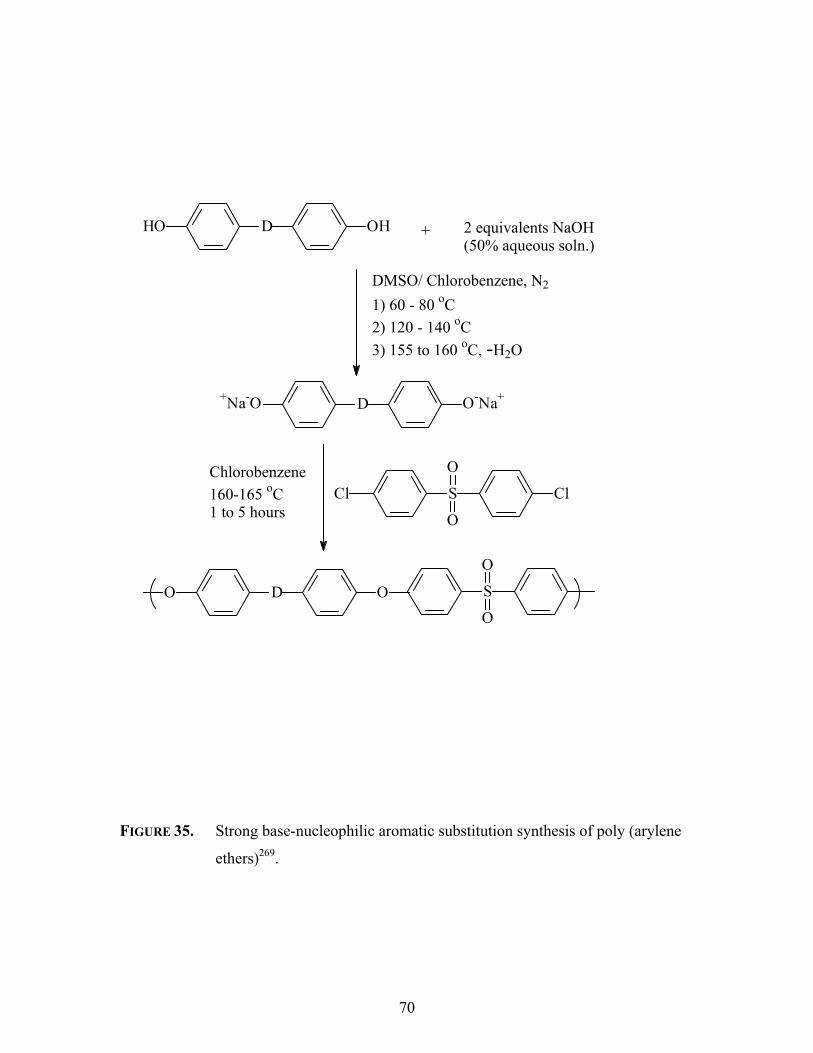
70
FIGURE 35. Strong base-nucleophilic aromatic substitution synthesis of poly (arylene
ethers)269.
HO D OH + 2 equivalents NaOH(50% aqueous soln.)
DMSO/ Chlorobenzene, N2
1) 60 - 80 oC2) 120 - 140 oC3) 155 to 160 oC, -H2O
+Na-O D O-Na+
Cl S Cl
O
O
Chlorobenzene160-165 oC1 to 5 hours
O D O S
O
O

71
and cleave the activated aromatic ether linkages of the polymer causing a reduction in the
final molecular weight of the polymer.
The presence of an insufficient amount of base is also detrimental to the
polymerization. Besides offsetting the one-to-one stoichiometry of reactive groups, the
free bisphenols can hydrogen bond with other phenolates in the reaction mixture270. A
FIGURE 35A. Hydrogen bonding of a phenol and a phenolate270.
depiction is given in Figure 35a. This interaction decreases the nucleophilicity of the
phenolate.
The importance of the exclusion of moisture was also noted by Johnson et al.,
since water could hydrolyze the activated dihalide monomer, causing similar
stoichiometric problems as excess base.
270 Storozhuk, I.P.; Bakhmotov, V.I.; Mikitaev, A.K.; Waletskii, P.M.; Yu, I.; Musaev, V.; Korshak, V.; Fedin, E.I, Vysokomol. Soed.,
A 1977, 19(8), 800.
O O-
CH3
CH3 HO O
CH3
CH3
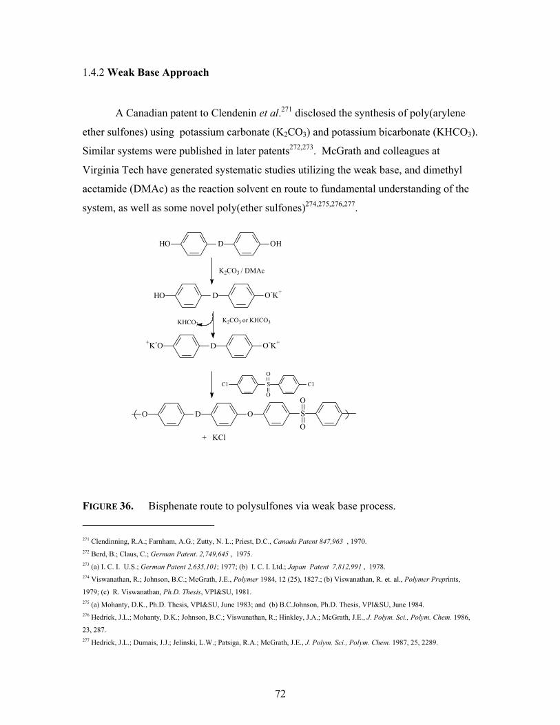
72
1.4.2 Weak Base Approach
A Canadian patent to Clendenin et al.271 disclosed the synthesis of poly(arylene
ether sulfones) using potassium carbonate (K2CO3) and potassium bicarbonate (KHCO3).
Similar systems were published in later patents272,273. McGrath and colleagues at
Virginia Tech have generated systematic studies utilizing the weak base, and dimethyl
acetamide (DMAc) as the reaction solvent en route to fundamental understanding of the
system, as well as some novel poly(ether sulfones)274,275,276,277.
FIGURE 36. Bisphenate route to polysulfones via weak base process.
271 Clendinning, R.A.; Farnham, A.G.; Zutty, N. L.; Priest, D.C., Canada Patent 847,963 , 1970. 272 Berd, B.; Claus, C.; German Patent. 2,749,645 , 1975. 273 (a) I. C. I. U.S.; German Patent 2,635,101; 1977; (b) I. C. I. Ltd.; Japan Patent 7,812,991 , 1978. 274 Viswanathan, R.; Johnson, B.C.; McGrath, J.E., Polymer 1984, 12 (25), 1827.; (b) Viswanathan, R. et. al., Polymer Preprints,
1979; (c) R. Viswanathan, Ph.D. Thesis, VPI&SU, 1981. 275 (a) Mohanty, D.K., Ph.D. Thesis, VPI&SU, June 1983; and (b) B.C.Johnson, Ph.D. Thesis, VPI&SU, June 1984. 276 Hedrick, J.L.; Mohanty, D.K.; Johnson, B.C.; Viswanathan, R.; Hinkley, J.A.; McGrath, J.E., J. Polym. Sci., Polym. Chem. 1986,
23, 287. 277 Hedrick, J.L.; Dumais, J.J.; Jelinski, L.W.; Patsiga, R.A.; McGrath, J.E., J. Polym. Sci., Polym. Chem. 1987, 25, 2289.
HO D OH
K2CO3 / DMAc
HO D O-K+
Cl S Cl
O
O
O D O S
O
O
+K-O D O-K+
K2CO3 or KHCO3
+ KCl
KHCO3

73
Viswanathan et al.274 proposed mechanisms for the synthesis of poly(arylene
ether sulfone) via the potassium carbonate process. There are two possible mechanisms.
Figure 36 displays the bisphenate route. Like the strong base route, the dimetal
FIGURE 37. Monophenolate mechanism to polysulfone via weak base process279.
HO D OH
K2CO3 / DMAc
HO D O-K+
Cl S Cl
O
O
O D O
HO D O
KHCO3
S Cl
O
O
S
O
O
A-B Type Intermediate
K2CO3 or KHCO3
S Cl
O
O
+K-O D O
+ KCl

74
bisphenate is formed, but in situ, followed by attack on two activated dihalides.
The alternative route is involves a monophenate species, shown below (Figure
37). The monophenolate mechanism was the preferred route274,278.
Priddy et al. studied model reactions to explore the kinetics of the weak and
strong base processes278,279. In the study, typical polymerization-type reactions were set
up under both weak base and strong base conditions. The kinetics of the reactions were
followed by taking samples from the reaction solutions as a function of time. After
workup, the isolated compounds were examined and the end-groups analyzed. In the
strong base reactions, both mono and disubstituted products were isolated essentially
immediately. However, the weak base approach yielded only mono substituted products
for the first 100 minutes of the reaction. The initial rate of formation of the disubstituted
product with the weak base method was much lower than the rate of formation of the
monosubstituted product. It was not until five hours of reaction time that the amount of
disubstituted product approached the concentration of monosubstituted product.
In addition to proposing a mechanism for the potassium carbonate/DMAc
process, this group of researchers was able to demonstrate that strict stoichiometry of the
bases via this route was not required. The strong base amount had to be controlled for
aforementioned reasons, however, high stoichiometric excesses (up to 50mol%) of
potassium carbonate did not cause any hydrolysis of the halide274. In fact, the typical
polymerization reactions employed up to 20 mol% excess potassium carbonate.
Notably, the need for a water azeotroping agent was established. During the
reaction potassium carbonate can undergo the following decomposition:
278 Priddy, D.; Smith, C. D.; McGrath, J. E. In 43rd Annual Southeastern Regional Meeting of the American Chemical Society:
Richmond, VA, 1991. 279 Priddy, D., Ph. D. Thesis, VPI & SU, 1994
K2CO3 H2CO3 + CO2KHCO3 H2O

75
The water formed can act as a nucleophile and, after reacting with the activated halide,
produce an unreactive bisphenol; this can be avoided by using toluene or xylene as
dehydrating agents.
While investigating semi-crystalline polymers, these researchers demonstrated the
applicability of higher boiling solvents, like N-methyl-2-pyrrolidone (NMP)275a, n-
cyclohexyl-2-pyrrolidone (CHP)275b, and sulfolane, to the weak base process. CHP is not
miscible with water at elevated temperatures, so an azeotroping agent is not necessary.
However, CHP is not as polar as NMP and co-solvent systems were necessary to keep the
reagents, intermediates, and polymers solubilized. The potassium carbonate-weak base
process has successfully been applied to many other polymer systems280,281,282,283,284,285.
Kricheldorf and collaborators have developed a bulk or melt variation of
nucleophilic aromatic substitution. Commonly referred to as the Kricheldorf Method,
silylated bisphenols react with activated difluorides to yield various poly (arylene
ethers)286,287. Other dihalides produce exclusively low molecular weight products. The
polymerization by this type of reaction is an extension of small molecule reactions for
trimethylsilyl ethers, esters, etc.288. The silylated compounds, such as bisphenols,
diamines, etc., can be purified by distillation. A catalytic amount of cesium fluoride is
used in the desilylation reaction289. The reaction is given in Figure 38. The polymer can
be used directly after synthesis since fluorotrimethylsilane, the volatile by-product, can
be vacuumed distilled from the reactor. The formation of the strong fluorine-silicon bond
and the volatility of the by-products limit any equilibrium to be established for the
polymer production.
280 Smith, C.D.; Grubbs, H.; Webster, H.F.; Gungor, A.; Wightman, J.P.; McGrath, J.E., High Performance Polymer 1991, 3(4), 211. 281 Mohanty, D.K.; Lin, T.S.; Ward, T.C.; McGrath, J.E., Sampe Symp. 1986, 31, 945. 282 Wang, S.; Ji, Q.; Tchatchoua, C.N.; Shultz, A.R.; McGrath, J.E., J. Polym. Sci.: Polym. Phys. Ed. 1999, 37, 1849. 283 Miyatake, K.; Hay, A.S., J. Polym. Sci., Part A: Polym. Chem. 2001, 39, 3770. 284 Srinivasan, S.A.; McGrath, J. E., Polymer 1998, 39 (12), 2415. 285 Shobha, H.K.; Smalley, G.R.; Sankarapandian, M; McGrath, J.E., ACS Polymer Preprints 2000, 41, 180. 286 Kricheldorf, H.R.; Bier, G., J. Polym. Sci.Polym. Chem. Ed. 1983, 21, 2283. 287 Kricheldorf, H.R.;Jahnke, p, Makromol. Chem. 1990, 191, 2027. 288 Fieser, M., Reagents for Organic Synthesis,Vol. 10, Wiley: New York, 1982. 289 Kricheldorf, H.R.; Delius, U.; Tonnes, K.U. New Polym. Mater. 1988, 1, 127.

76
FIGURE 38. Synthesis of poly (arylene ethers) via silyl ether displacement
The proposed silyl ether displacement mechanism is shown below. It involves,
first, the conversion of the silyl ether into the cesium phenolate followed by attack of the
phenolate on the activated halide monomer yielding a new ether linkage. Even though
the catalyst, typically CsF, concentration is low (0.1-0.3 mol%), it is very important in
this method for synthesizing high molecular weight poly (arylene ether sulfones).
FIGURE 38A. SILYL ETHER DISPLACEMENT REACTION MECHANISM
H3C Si
CH3
CH3
O Ar O Si
CH3
CH3
CH3 WF F
CsF (0.1 wt%)170-350 oC
H3C SiCH3
CH3
F
O Ar O W
Where Ar = Aryl Group, W = electron withdrawing group
O SiCH3
CH3
CH3Ar + Cs+ F- F SiCH3
CH3
CH3Ar O-Cs+ +
Ar O-Cs+ + F Ar2 Ar O Ar2 + CsF
(1)
(2)

77
CHAPTER 2
EXPERIMENTAL
Condensation or step-growth polymerizations involve the stepwise, sequential
condensation of functional monomers. To produce high molecular weight, linear
polymers, several general requirements need to be satisfied. These critical requirements
include (1) difunctionality, (2) one-to-one stoichiometry, (3) high monomer and reagent
purity, and (4) very high (> 99%) conversions. The following sections describe the
careful purification of solvents and monomers required for these polymerizations.
2.1 Solvent Purification
2.1.1 N,N-Dimethylacetamide (DMAc)
H3C C N
CH3
CH3O
Source: Fisher Scientific
Molecular Weight: 89.13 g/mol
Purification: DMAc was dried over calcium hydride (CaH) or
phosphorus pentoxide (P2O5) for at least 12 hours. DMAc was distilled under
reduced pressure (~ 80 oC) and stored over molecular sieves under nitrogen.
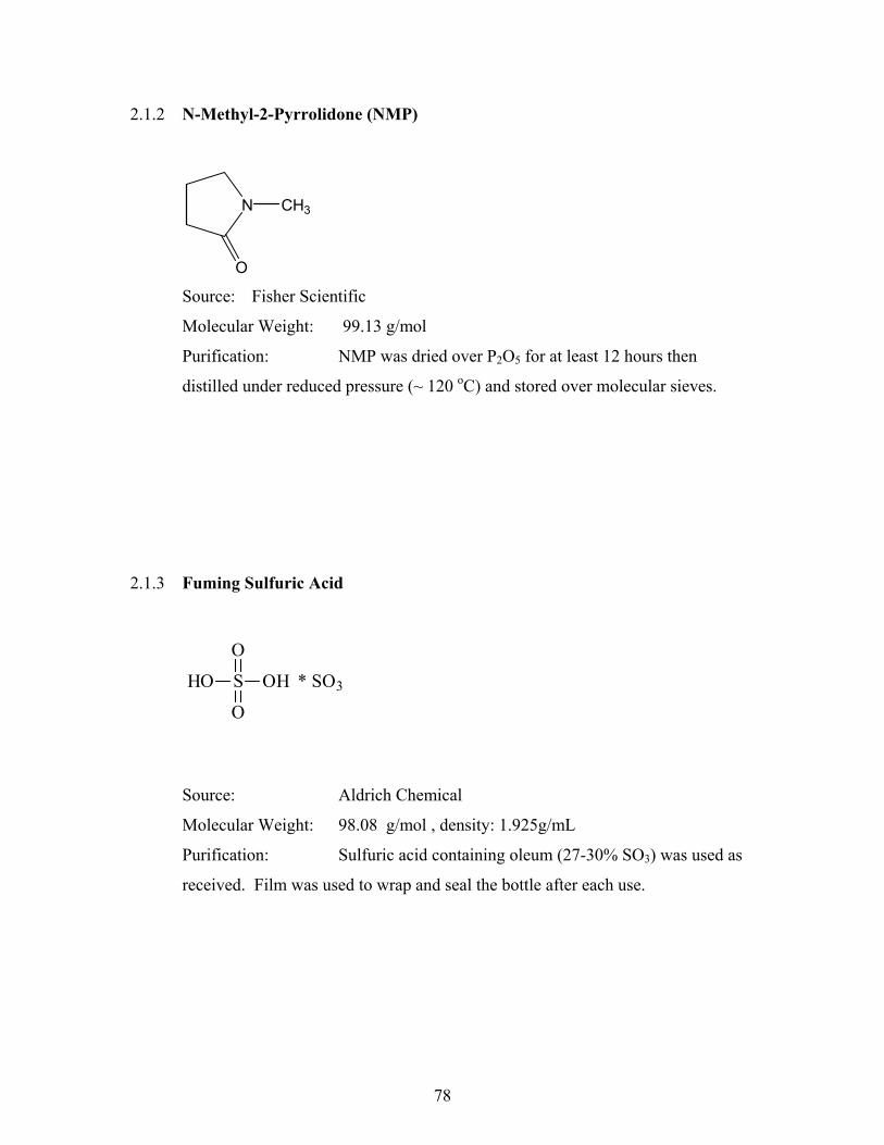
78
2.1.2 N-Methyl-2-Pyrrolidone (NMP)
N CH3
O Source: Fisher Scientific
Molecular Weight: 99.13 g/mol
Purification: NMP was dried over P2O5 for at least 12 hours then
distilled under reduced pressure (~ 120 oC) and stored over molecular sieves.
2.1.3 Fuming Sulfuric Acid
Source: Aldrich Chemical
Molecular Weight: 98.08 g/mol , density: 1.925g/mL
Purification: Sulfuric acid containing oleum (27-30% SO3) was used as
received. Film was used to wrap and seal the bottle after each use.
HO S OH
O
O
* SO3

79
2.1.4 Toluene
Source: Fisher
Molecular Weight: 92.14 g/mol
Purification: Toluene was transferred into 250 mL round-bottom flasks
and stored over molecular sieves under nitrogen.
2.1.5 Ethanol or Ethyl Alcohol
Source: Aldrich
Molecular Weight: 46.07 g/mol
Purification: Absolute (99%) ethanol was used as a coagulating and / or
recrystallization solvent and used without any purification.
CH3
H C
H
H
C
H
H
OH

80
2.1.6 Methanol or Methyl Alcohol
Source: Fisher
Molecular Weight: 32.04 g/mol
Purification: Methanol was used as a coagulating and / or
recrystallization solvent and was used without any purification.
2.1.7 Isopropyl Alcohol or 2-Propanol or Isopropanol
Source: Fisher
Molecular Weight: 60.01 g/mol
Purification: Isopropanol was used as a coagulating and / or as a
recrystallization solvent and used without any purification.
H C
H
H
OH
C C C
OH
H
H
H
H H
H
H

81
2.1.8 1,2-Dichloroethane (DCE)
Source: Aldrich
Molecular Weight: 98.96 g/mol
Purification: A.C.S. reagent grade 1,2-dichloroethane was stored over
molecular sieves, otherwise used without any purification.
2.1.9 1,1,2-Trichloroethane (TCE)
Source: Aldrich
Molecular Weight: 133.41 g/mol
Purification: 1,1,2-trichloroethane was supplied containing 2-propanol
(~5%). Therefore, the 2-propanol was separated via distillation and discarded,
while the 1,1,2-trichloroethane was distilled onto molecular sieves and stored
under nitrogen.
C C
H
Cl
H
H
Cl
H
C C
H
Cl
H
H
Cl
Cl

82
2.2 Reagents and Purification of Monomers
2.2.1 Bisphenol A (Bis A) or 2,2’-bis(4-hydroxyphenol)propane or 4,4'-
isopropylidenediphenol
Source: Dow Chemical
Molecular Weight: 228.29 g/mol
Melting Point: 152-153 oC
Purification: Bisphenol A was recrystallized from a 25% (w/v) solution
of toluene. After refluxing for several hours, the solution was allowed to cool to
room temperature. The milky white crystals were collected by filtration and dried
in a vacuum for over 12 hours at 60 oC, then at least 12 hours at 90 oC.
2.2.2 4,4’-Biphenol (BP)
Source: BP-Amoco
Molecular Weight: 186.21 g/mol
Melting Point: 282-284 oC
Purification: Monomer grade biphenol was used as received. Prior to
use, it was dried in a vacuum oven for at least 12 hours at 100 oC. Biphenol can
be recrystallized from deoxygenated acetone or from toluene.
HO C
CH3
CH3
OH
OHHO
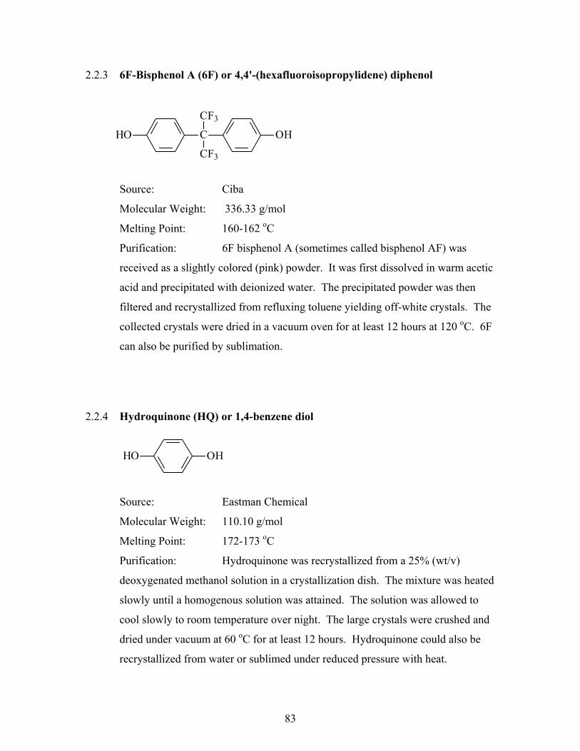
83
2.2.3 6F-Bisphenol A (6F) or 4,4'-(hexafluoroisopropylidene) diphenol
Source: Ciba
Molecular Weight: 336.33 g/mol
Melting Point: 160-162 oC
Purification: 6F bisphenol A (sometimes called bisphenol AF) was
received as a slightly colored (pink) powder. It was first dissolved in warm acetic
acid and precipitated with deionized water. The precipitated powder was then
filtered and recrystallized from refluxing toluene yielding off-white crystals. The
collected crystals were dried in a vacuum oven for at least 12 hours at 120 oC. 6F
can also be purified by sublimation.
2.2.4 Hydroquinone (HQ) or 1,4-benzene diol
Source: Eastman Chemical
Molecular Weight: 110.10 g/mol
Melting Point: 172-173 oC
Purification: Hydroquinone was recrystallized from a 25% (wt/v)
deoxygenated methanol solution in a crystallization dish. The mixture was heated
slowly until a homogenous solution was attained. The solution was allowed to
cool slowly to room temperature over night. The large crystals were crushed and
dried under vacuum at 60 oC for at least 12 hours. Hydroquinone could also be
recrystallized from water or sublimed under reduced pressure with heat.
HO C
CF3
CF3
OH
HO OH

84
2.2.5 4-4’-Dichlorodiphenyl sulfone (DCDPS) or Bis (4-chlorophenyl) sulfone
Source: BP-Amoco (now Solvay)
Molecular Weight: 287.13 g/mol
Melting Point: 145-147 oC
Purification: Monomer grade dichlorodiphenyl sulfone was used as
received. Prior to use, it was dried in a vacuum oven for at least 12 hours at 100 oC. DCDPS can be recrystallized from toluene and yields large crystals that are
pulverized prior to drying.
2.2.6 Potassium Carbonate (Anhydrous)
Source: Aldrich
Molecular Weight: 138.21 g/mol
Melting Point: Not determined.
Purification: Potassium carbonate was dried under vacuum at 120 oC for
at least 12 hours prior to use.
S
O
O
Cl Cl
C
O
O O KK

85
2.2.7 4,4’-Difluorodiphenyl Sulfone (DFDPS) or Bis (4-fluorophenyl) sulfone
Source: Aldrich
Molecular Weight: 254.25 g/mol
Melting Point: 100-102 oC.
Purification: Difluorodiphenyl sulfone (99%) was dried under vacuum at
65 oC for at least 12 hours prior to use. DFDPS could be recrystallized from
toluene and yield off-white crystals. Also, one attempt was made to synthesize
difluorodiphenyl sulfone from dichlorodiphenyl sulfone, using a reported
synthetic route290, will be discussed under the Monomer Synthesis section.
2.2.8 Chlorosulfonic acid
Source: Aldrich
Molecular Weight: 116.52 g/mol
Purification: Chlorosulfonic acid was used as received. Film was used
to wrap and seal moisture from the contents. The container was stored in a
desiccator once opened.
S
O
O
F F
Cl S OH
O
O

86
2.2.9 Chlorotrimethylsilane or Trimethylchlorosilane
Source: Aldrich
Molecular Weight: 108.64 g/mol
Purification: Chlorotrimethylsilane (98%) was used as received. A
positive pressure of nitrogen was used when syringing the reagent from the sealed
container. Chlorotrimethylsilane was stored in a desiccator once opened.
290 Viswanathan, R., Ph.D. Thesis VPI & SU, 1981, p.83.
Cl Si
CH3
CH3
CH3

87
2.3 Monomer Synthesis
2.3.1 Sodium Salt of 3,3’-Disulfonated –4,4’-( bis-isopropylidene) diphenol or
Sulfonated Bisphenol A
Source: Synthesized in house
Molecular Weight: 476.33 g/mol
Melting Point: Not observed below 350 oC.
Reagents: Sulfonated bisphenol A was synthesized using bisphenol A
and 97% concentrated sulfuric acid (Fisher) via electrophilic aromatic
substitution.
Procedure: To a 100-mL, 3 necked round bottom flask, fitted with a
condenser, nitrogen inlet, and an overhead mechanical stirrer, 20 g (0.088 mol)
bisphenol A and 40 mL sulfuric acid were added. The mixture was stirred
vigorously at 30 oC for 18 hours. The mixture underwent several color changes
during this time (a tan to an orange to a yellow). The final mixture was
poured into a 200 mL ice bath stirred by a magnetic stir bar. Upon adding to
water, insoluble solids precipitated to the bottom of the flask. The aqueous
solution was filtered, neutralized with 2M NaOH to a final pH 8. Next, 100 g
sodium chloride was added and the mixture was allowed to stand overnight.
Finally, the solid precipitate was collected by filtration and recrystallized from
isopropyl alcohol and water (10/1). Yield: 20%.
NaO C
CH3
CH3
ONa
NaO3S SO3Na

88
2.3.2 Sodium Salt of 3,3’-Disulfonated-4,4’- Biphenol or Sulfonated Biphenol
Source: Synthesized in house
Molecular Weight: 434.24 g/mol
Melting Point: Not observed below 350 oC.
Reagents: Disulfonated biphenol was synthesized using 4,4’-biphenol
and 97% concentrated sulfuric acid via electrophilic aromatic substitution.
Procedure: To a 100- mL, 3 necked round bottom flask, fitted with a
condenser, nitrogen inlet, and an overhead mechanical stirrer, 20 g (0.107 mol)
biphenol and 40 mL sulfuric acid were added. The mixture was stirred vigorously
at 30 oC for 18 hours. The mixture underwent several color changes during this
time (off-white orange yellow). The final mixture was poured into a 200 mL
ice bath stirred by a magnetic stir bar. The isolation steps were similar to those
described above for sulfonated bisphenol A, except a methanol and water mixture
(9/1, v/v) was used for recrystallization. Yield: 75%.
ONaNaO
NaO3S SO3Na

89
FIGURE 39. Synthesis of novel disulfonated bisphenols.
XHO OH + conc. H2SO4
30-40 oC, 18 Hours
XHO OH
HO3S SO3HDeionized H2O, 2M NaOH, NaCl
XNaO ONa
NaO3S SO3Na
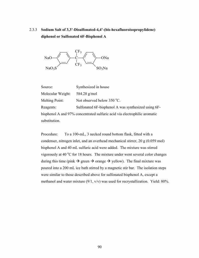
90
2.3.3 Sodium Salt of 3,3’-Disulfonated-4,4’-(bis-hexafluoroisopropylidene)
diphenol or Sulfonated 6F-Bisphenol A
Source: Synthesized in house
Molecular Weight: 584.28 g/mol
Melting Point: Not observed below 350 oC.
Reagents: Sulfonated 6F-bisphenol A was synthesized using 6F-
bisphenol A and 97% concentrated sulfuric acid via electrophilic aromatic
substitution.
Procedure: To a 100-mL, 3 necked round bottom flask, fitted with a
condenser, nitrogen inlet, and an overhead mechanical stirrer, 20 g (0.059 mol)
bisphenol A and 40 mL sulfuric acid were added. The mixture was stirred
vigorously at 40 oC for 18 hours. The mixture under went several color changes
during this time (pink green orange yellow). The final mixture was
poured into a 200 mL ice bath stirred by a magnetic stir bar. The isolation steps
were similar to those described above for sulfonated bisphenol A, except a
methanol and water mixture (9/1, v/v) was used for recrystallization. Yield: 80%.
NaO C
CF3
CF3
ONa
NaO3S SO3Na

91
2.3.4 Sodium Salt of 3,3’-Disulfonated-4,4’-dichlorodiphenyl sulfone (SDCDPS)
Source: Synthesized in house
Molecular Weight: 491.24 g/mol
Melting Point: Not observed below 350 oC.
Reagents: Disulfonated dichlorodiphenyl sulfone was synthesized
using 4,4’-dichlorodiphenyl sulfone and fuming sulfuric acid via electrophilic
aromatic substitution.
Procedure: The procedure utilized was slightly modified from previously
reported procedures164,291. To a 100-mL, three necked flask equipped with a
mechanical stirrer and a nitrogen inlet/outlet was added 28.7 g of DCDPS
dissolved in 60mL 30% fuming sulfuric acid. The solution was heated to 110 oC
for 6 hours. The reaction mixture was allowed to cool to room temperature and
added into 400ml of ice-water. Next, 180 g of NaCl was added and, subsequently,
the disodium salt of disulfonated dichlorodiphenyl sulfone precipitated as a white
powder. The latter was filtered and re-dissolved in 400 mL of cold deionized
water, treated by 2N NaOH aqueous solution to a pH of 6~7, and finally an excess
amount of NaCl was added again to salt out the sodium form of the sulfonated
monomer. The crude product was filtered and recrystallized from a mixture of
291 L.M. Robeson, and M. Matzner, US Patent 4,380,598, 1983.
S
O
O
Cl Cl
S SO
O ONaNaO O
O

92
alcohol (methanol or isopropanol) and deionized water (9/1, v/v), producing white
needle-like crystals. Yield: 87%.
2.3.5 Sodium Salt of 3,3’-Disulfonated-4,4’-difluorodiphenyl sulfone (SDFDPS)
Source: Synthesized in house
Molecular Weight: 458.33 g/mol
Melting Point: Not observed below 350 oC.
Reagents: Disulfonated difluorodiphenyl sulfone was synthesized
using 4,4’-difluorodiphenyl sulfone and fuming sulfuric acid via electrophilic
aromatic substitution.
Procedure: To a 250-mL, three necked flask equipped with a mechanical
stirrer and a nitrogen inlet/outlet was added 25 g of DCDPS dissolved in 50mL
30% fuming sulfuric acid. The solution was heated to 110 oC for 6 hours with
vigorous stirring. The reaction mixture was allowed to cool to room temperature
and added into 400ml of ice-water. The remaining steps are the same as for the
SDCDPS synthesis, except recrystallization was accomplished with ethyl alcohol
and water (8/1). Yield: 70%
S
O
O
F F
S SO
O ONaNaO O
O

93
Figure 40. General synthesis of disodium salt of the disulfonated sulfone dihalide
monomers
S
O
O
X X + SO3/H2SO4
110 oC, 6 Hours
S
O
O
X X
HO3S SO3H
S
O
O
X X
NaO3S SO3Na
Deionized H2O, NaCl2N NaOH, NaCl

94
2.3.6 Synthesis of 4,4’-Difluorodiphenyl Sulfone
Source: In house
Molecular Weight: 254.25 g/mol
Melting Point: 96 - 98 oC.
Reagents: 4,4’-dichlorodiphenyl sulfone (DCDPS), anhydrous
potassium fluoride (KF), and sulfolane.
Procedure: 100 grams (1.75 mols) of dried KF (finely powdered) were added
to 300 mL of sulfolane contained in a 1000-mL 3-necked round bottom flask
equipped with an overhead mechanical stirrer, a nitrogen inlet, and a condenser.
Vigorous stirring was used to produce fine dispersion, while heating at 100 oC
under nitrogen. 25 grams (0.75 mols) DCDPS were added to the dispersion, then
the mixture was heated to reflux overnight. After about 20 hours, the reaction
mixture was cooled to room temperature and poured into 500 mL of deionized
water under vigorous agitation. The precipitated powder was filtered and washed
several times with water to remove any salts. After drying at 60 oC, the crude
powder product was distilled under vacuum and the main fraction was collected.
The difluorodiphenyl sulfone (DFDPS) was recrystallized from toluene. Yield:
65%. Note: All copolymerizations utilized commercial DFDPS.
FIGURE 41. Synthesis of difluorodiphenyl sulfone from dichlorodiphenyl sulfone290.
S
O
O
Cl Cl + S
O
O
F FKFSulfolane
reflux
+ KCl

95
2.4 Copolymer Synthesis
The direct synthesis of sulfonated copolymers by polycondensation was achieved
via nucleophilic aromatic substitution mechanisms. The fluorine containing sulfone
monomers (DFDPS and SDFDPS) are more reactive than the corresponding chloro-
dihalides (DCDPS and SDCDPS). Due to their inherent differences, two slightly
different synthetic procedures were developed to obtain high molecular weight polymers
that will successfully generate tough, ductile films. Strict stoichiometric control was
necessary for both systems.
2.4.1 DCDPS/SDCDPS Copolymer Synthesis
Although the reactivities of the various bisphenols were different, the basic
polymerization procedure was the same. A typical polymerization for all sulfonated
copolymers will be described using the bisphenol A-40 system: Firstly, 1.2624g
(5.5mmol) 4,4’-bisphenol A, 0.9621g (3.3mmol) DCDPS, and 1.0806g (2.2mmol)
SDCDPS were added to a 3-neck flask equipped with overhead mechanical stirrer,
nitrogen inlet and a Dean Stark trap. Next, 1.15 mole equivalent of potassium carbonate
and NMP were introduced to afford a 20% solids concentration. Toluene (NMP/Toluene
= 2/1, v/v) was used as an azeotropic agent. The reaction mixture was heated under
reflux at 150ºC for 4 hours to dehydrate the system. The temperature was raised slowly
to 190ºC by controlled removal of the toluene. The reaction mixture was reacted for 16-
30 hours during which the solution became very viscous. The solution was cooled to
room temperature and diluted with DMAc. The solution was filtered to remove most of
the salts and isolated as swollen strings by addition to stirred deionized water. The
precipitated copolymer was washed several times with deionized water to further remove
salts, including soaking in deionized water at 60 oC overnight. Finally, the filtered
copolymer was vacuum dried at 120ºC for 24 hours. Copolymers with other bisphenols
and dihalide compositions were also prepared by this procedure. The homopolymers for
each respective bisphenol was synthesized using DCDPS and a polymerization
96
temperature of 175 oC. Each homopolymer was isolated by precipitation into methanol
and water (11/1, v/v) stirred in a blender.
2.4.2 DFDPS/SDFDPS Copolymer Synthesis
The DFDPS/SDFDPS system was employed for only a few copolymers in which
ductile films were not easily achieved using the DCDPS/SDCDPS synthesis procedure.
These include the copolymerization of 6F bisphenol A with 50% and 60% SDFDPS,
bisphenol A with 60% SDFDPS, biphenol with 50% and 60% SDFDPS, and
hydroquinone with 50% and 60% SDFDPS. Copolymerizations utilizing DFDPS and
SDFDPS required less thermal energy due to the enhanced comonomer reactivity. A
typical reaction is presented for hydroquinone-50. First, 2.018g (18mmol) hydroquinone,
2.353g (9 mmol) DFDPS, and 4.201g (9 mmol) SDFDPS were added to a simple 3-neck
flask equipped with mechanical stirrer, nitrogen inlet and a Dean Stark trap. Next, 1.15
mole equivalent of potassium carbonate and DMAc were introduced to afford a 20%
solids concentration. Toluene was used as an azeotropic agent (DMAc/Toluene = 2/1,
v/v). The reaction mixture was heated under reflux at 150ºC for 4 hours to dehydrate the
system. Toluene was slowly removed to raise the temperature to 175ºC and held constant
for at least 16 hours. The viscous solution was cooled and diluted with more DMAc.
The copolymer isolation steps are as given above for DCDPS/SDCDPS polymerizations.

97
FIGURE 42. Synthesis of sulfonated poly (arylene ether sulfone) copolymers via direct
polymerization.
XHO OH
S
O
O
Cl Cl
+Na-O3S SO3-Na+
S
O
O
Cl Cl
XO O
XO O
S
O
O
S
O
O
+Na-O3S SO3-Na+
NMP, Toluene, K2CO3Reflux 145oC, 5hrs19
70oC, 20hrs under N2
CH3
C
CH3
CF3
C
CF3
orWhere X= a bond,
190oC, 16-40H, N2

98
2.5 Polymer Post - Sulfonation
The sulfonation of poly (arylene ethers) has been well studied, as surveyed in
sections of the Literature Review (Chapter 1). Some investigation of the sulfonation of
control (homopolymers) polymers based on bisphenol A, biphenol, and 6F bisphenol A
were conducted to provide comparative materials to the directly sulfonated copolymers.
The sulfonation technique utilized in this study was generally similar to published
procedures108,109. A typical polymer sulfonation will be described using bisphenol A
based poly (arylene ether sulfone), chlorosulfonic acid (50 mol%), chlorotrimethylsilane,
and 1,2-dichloroethane as follows:
To a 100 mL, 3-necked round bottom flask fitted with a mechanical stirrer, condenser,
and an addition funnel with a nitrogen connection, 5 grams of dried Bisphenol A
polysulfone (11.3mmol) were dissolved in 60 mL 1,2-dichloroethane (5-10 % wt/v
solution was typical). Next, a mixture of chlorotrimethylsilane (1.228g, 12.5mmol)
diluted in 10 mL 1,2-dichloroethane was added. Finally, a mixture of 0.658 grams
(0.0056mmol) chlorosulfonic acid in 10 mL 1,2-dichloroethane was added dropwise over
30 minutes. The reaction solution was stirred at a high rate overnight (~24 hours) at a
constant temperature of 30 oC. The reaction mixture generally remained homogeneous
(i.e., in solution) during the entire reaction time. After the desired time, the reaction
solution was added dropwise into stirred methanol, and washed with methanol and then
cold water. The polymers were dried in a vacuum oven at ~90 oC for at least 24 hours.
Note: The post-sulfonated polymers that were soluble in methanol were subsequently
recovered by distillation via rotovap of the solvents, dissolved in DMAc and cast into
films on glass substrates. All dried sulfonated polymers were stored in a desiccator.
Similar reaction conditions were used for other compositions (i.e., mol%
chlorosulfonic acid), and homopolymers. Note: Biphenol based poly (ether sulfones)
were not readily soluble in 1,2-dichloroethane and were alternatively dissolved in 1,1,2-
trichloroethane for sulfonation.

99
FIGURE 43 Synthesis of sulfonated poly(arylene ether sulfone)s via the silyl ester of
chlorosulfonic acid.
X o s
o
o
o + m ClSO3Si(CH3)3
n
1,2-DCE-m HCl
n
X o s
o
o
o
SO3Si(CH3)3
CH3OH-m CH3OSi(CH3)3
SO3H
X o s
o
o
o
n

100
2.6 Characterization
2.6.1 Nuclear Magnetic Resonance (NMR) Spectroscopy
Proton (1H) and Carbon (13C) Nuclear Magnetic Resonance were used to obtain
the chemical composition of the monomers and polymers utilized, both commercial and
synthesized, in this research. Samples were dissolved in appropriate deuterated solvents
(DMSO-d6, CDCl3, or D2O), at a typical concentration of 10% (0.1g / 1 mL). NMR
spectra were obtained on a Varian Unity Spectrometer operating at 400 MHz. 1H and 13C
spectra were referred to tetramethylsilane (TMS) at 0 ppm.
2.6.2 Fourier Transform Infrared (FTIR) Spectroscopy
FTIR was utilized to confirm the functional groups of synthesized homo-and
copolymers. Measurements were conducted on a Nicolet Impact 400 FTIR Spectrometer
using thin solution-cast polymer films.
2.6.3 Gel Permeation Chromatography (GPC) or Size Exclusion Chromatography
(SEC)
GPC measurements were used to determine molecular weight and molecular
weight distributions of synthesized homopolymers. GPC was conducted with a Waters
GPC/ALC 150C instrument equipped with a differential refractometer detector and an
on-line differential viscometer (Viscotek 150R) coupled in parallel. TriSEC GPC
Software V2.70e (Viscotek) was used to acquire and analyze the data. GPC
measurements were performed using an NMP (HPLC grade) mobile phase, containing
0.02 M P2O5, at a flow rate of 1.0 ml/min and an injection volume of 200 µl with the
polymer concentration of approximately 4 mg/ml. The stationary phase was crosslinked
polystyrene gel (Waters µ styragel HT 103 Å, mean particle diameter 10 µm) packed in

101
three (7.8 mm I.D. x 30 cm) stainless steel columns. The column- compartments, lines
and detectors were maintained at a temperature of 60 oC during measurements. A series
of polystyrene standards having narrow molecular weight distributions (Polymer
Laboratory) were employed to generate a universal calibration curve292,293. Number
average molecular weight (Mn), weight average molecular weight (Mw) and
polydispersity (Mw/Mn) were determined by using the universal calibration mentioned
above.
2.6.4 Intrinsic Viscosity Determinations ([η])
The measurements of intrinsic viscosity of homo- and sulfonated poly(arylene
ether sulfones) were performed using a Cannon- Ubbelohde viscometer, thermostatically
controlled in a water bath. Intrinsic viscosities were measured at 25 oC in NMP. Intrinsic
viscosities provide information on the size of a polymer molecule in solution. Typically,
the intrinsic viscosity provides a qualitative inference of molecular weight. Intrinsic
viscosities were very important in this dissertation since GPC could not be effectively
used for sulfonated copolymers.
2.6.5 Thermogravimetric Analysis (TGA)
Dynamic TGA was performed on a Perkin Elmer TGA7 instrument in either air or
nitrogen to assess the thermal and thermo-oxidative stability of sulfonated poly(arylene
ether sulfones). The samples were heated at a rate of 10 oC/min. Weight loss was
measured and reported as a function of temperature. The thermal stability of the
polymers was generally reported at the observed temperature of 5% weight loss.
292 Konas, M.; Moy, T.M.; Rogers, M.E.; Shultz, A.R.; Ward, T.C.; McGrath, J.E., J. Polym. Sci., Part B: Polym. Phys. 1995, 33,
1429. 293 Konas, M.; Moy, T.M.; Rogers, M.E.; Shultz, A.R.; Ward, T.C.; McGrath, J.E., J. Polym. Sci., Part B: Polym. Phys. 1995, 33,
1441.
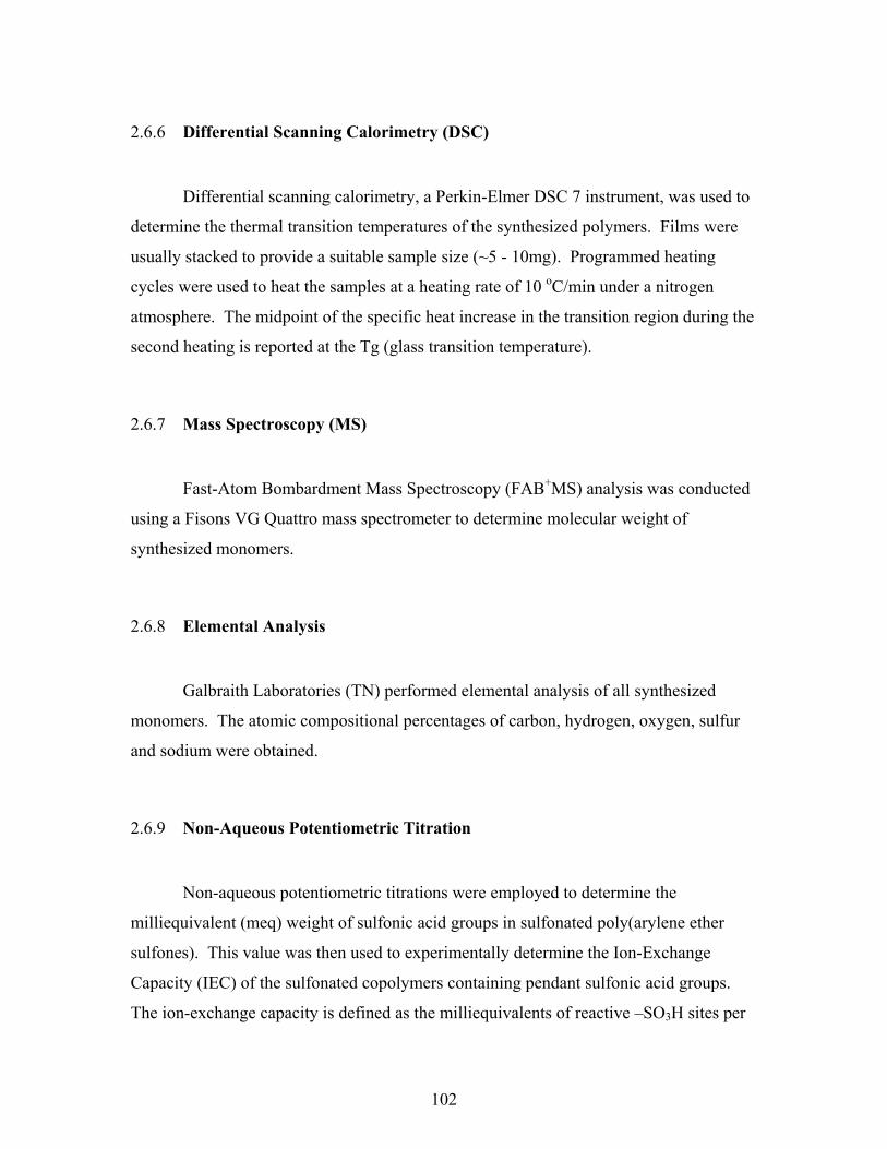
102
2.6.6 Differential Scanning Calorimetry (DSC)
Differential scanning calorimetry, a Perkin-Elmer DSC 7 instrument, was used to
determine the thermal transition temperatures of the synthesized polymers. Films were
usually stacked to provide a suitable sample size (~5 - 10mg). Programmed heating
cycles were used to heat the samples at a heating rate of 10 oC/min under a nitrogen
atmosphere. The midpoint of the specific heat increase in the transition region during the
second heating is reported at the Tg (glass transition temperature).
2.6.7 Mass Spectroscopy (MS)
Fast-Atom Bombardment Mass Spectroscopy (FAB+MS) analysis was conducted
using a Fisons VG Quattro mass spectrometer to determine molecular weight of
synthesized monomers.
2.6.8 Elemental Analysis
Galbraith Laboratories (TN) performed elemental analysis of all synthesized
monomers. The atomic compositional percentages of carbon, hydrogen, oxygen, sulfur
and sodium were obtained.
2.6.9 Non-Aqueous Potentiometric Titration
Non-aqueous potentiometric titrations were employed to determine the
milliequivalent (meq) weight of sulfonic acid groups in sulfonated poly(arylene ether
sulfones). This value was then used to experimentally determine the Ion-Exchange
Capacity (IEC) of the sulfonated copolymers containing pendant sulfonic acid groups.
The ion-exchange capacity is defined as the milliequivalents of reactive –SO3H sites per
103
gram of polymer and have units, therefore, of meq/g. The measured IEC values are
compared to the theoretical or calculated IEC value based on the moles of sulfonated
dihalide monomer charged to the reaction flask. Potentiometric titrations were performed
using a MCI GTOS Automatic Titrator equipped with a standard calomel electrode and a
reference electrode.
A typical sulfonated poly(arylene ether sulfone) titration is conducted as follows:
Tetra methyl ammonium hydroxide (TMAH) was utilized as titrant (~ 0.02 N) for the
titration of sulfonic acid groups in the polymer. The titrant was standardized against dry
potassium hydrogen phthalate (KHP) immediately prior to titrating. Sulfonated polymers
were dried at ~120 oC before being weighing and dissolving in dimethyl acetamide
(DMAc). The end-point was detected as the maximum of the first derivative for the
potential versus the used volume of titrant. The end point was then used to calculate the
IEC (meq/g) of the sulfonated membrane. The reported experimentally calculated IECs
were those of the average of at least three titrated samples.
2.6.10 Film Preparation
Films were prepared by casting solutions of homo- and sulfonated copolymers
dissolved in DMAc on clean glass substrates. The concentration of the polymer solution
was varied from 5 – 15% (w/v) which allowed some control over the thickness of the
films. Polymer solutions were filtered to remove particulates using a disposable syringe
and disc filters ( 0.45µm) prior to casting. Removal / evaporation of DMAc was
accomplished via an infrared lamp in an inert (N2) environment with gradual increasing
lamp intensity over 24 hours. The films were then placed in a vacuum oven at 120 oC for
approximately 20 hours and 150 oC for four hours. For thicker films, a stainless steel ring
(3’’ diameter) was used on top of the glass substrate to function as a mold.

104
2.6.11 Water Sorption/Uptake
Water uptake was determined on films of all synthesized poly(arylene ether
sulfones) in both their salt and acid forms. The acid-form films were dried at 120 oC and
the salt-form films were thoroughly dried at 150 oC under vacuum to a constant weight
which was recorded. The dried film was then immersed in water at 30 oC and
periodically weighed on an analytical balance until constant water uptake weight was
obtained. Typically, the equilibrium water sorption occurred within 72 hours. Some
films were examined for water sorption at 80 oC and handled in a similar manner to study
the effect of temperature on water sorption. The water uptake is reported as a percentage
and determined by taking the equilibrium weight difference between the wet film (Wwet )
and the dry film (Wdry) and dividing by the dry film (Wdry) weight. The equation is given
below.
Water uptake = %100×−
dry
drywet
WWW
2.6.12 Conductivity Measurements
Conductivity measurements were performed on membranes using the cell shown
in Figure 40. This cell geometry, developed by researchers at Los Alamos National
Laboratory, was chosen to ensure that the membrane resistance dominated the response
of the system. An impedance spectrum was recorded from 10MHz to 10Hz using a
Solatron 1260 Impedance/Gain-Phase Analyzer. The resistance of the film was taken at
the frequency which produced the minimum imaginary response. All impedance
measurements were performed at room temperature under full hydration conditions. The
proton conductivity is the reciprocal of the resistance and reported in units of Siemens per
centimeter (S/cm).

105
1
2
3
4 5
6
Legend 1. Teflon block 2. Thumbscrew 3. Open area to allow
equilibration with environment4. Membrane sample 5. Blackened Pt foil electrode 6. Pt lead
FIGURE 44. Schematic of Conductivity Cell294
2.6.13 Electron Spectroscopy for Chemical Analysis (ESCA)
ESCA, also known as XPS, was used to determine the surface atomic
concentration on thin films of 6F bisphenol A-based sulfonated poly(arylene ether
sulfone) copolymers. Mr. Frank Cromer of the Virginia Tech Chemistry Department
kindly conducted all ESCA experiments.
294 Zawodzinski, T. A.; Derouin, C.; Radzinski, S.; Sherman, R. J.; Smith, V. T.; Springer, T. E.; Gottesfeld, S. J., J Electrochem Soc.
1993, 140, 1041.

106
CHAPTER 3
RESULTS AND DISCUSSION
3.1 Introduction
The present research focused on the relationships between the chemical structure
of the bisphenol, the degree of sulfonation of the resulting sulfonated polymers, and a
variety of chemical, physical, and electrical properties. The physical properties of the
copolymers will be analyzed. Several different monomers were sulfonated in order to
systematically synthesize different copolymers for proton exchange membrane fuel cells.
The first section will describe monomer synthesis and characterization.
A systematic series of sulfonated copolymers derived from bisphenol A, biphenol,
hydroquinone, or 6F-bisphenol A was investigated. Each of the bisphenols was reacted
with 4,4’-dichlorodiphenyl sulfone (DCDPS) and the disodium salt of disulfonated
dichlorodiphenyl sulfone (SDCDPS). These permitted copolymers to be prepared which
were expected to vary in hydrolytic and oxidative stability as well as hydrophobicity.
Given that the sulfonated dihalide monomers are less reactive than their non-sulfonated
homologues, 4,4’-difluorodiphenyl sulfone (DFDPS) was also used. At higher molar
concentrations of sulfonated dihalide, difluorodiphenyl sulfone and the synthesized
disodium salt of disulfonated difluorodiphenyl sulfone (SDFDPS) were utilized to take
advantage of their respective increased reactivity compared to the dichloro- analogue.
Unsulfonated homopolymers were synthesized as control materials for direct comparison
with the novel sulfonated copolymers. Characterization of the homopolymers and
copolymers allowed identification of important properties for any useful applications.
Polymer structure, molecular weight, thermal and thermo-oxidative stabilities are thought
to be important parameters for fuel cell performance. In addition to these properties,
proton exchange membranes require reasonable water sorption and high proton
conductivity. Each of these parameters will be discussed and their unique importance to
novel sulfonated copolymers will be emphasized.

107
3.1.1 Sulfonated Bisphenols
As shown earlier, monomer modification is a powerful tool for varying the
properties of the resulting polymer. However, it is advantageous to use commercially
available and inexpensive materials whenever possible. This research made use of
commodity monomers and common solvents. Bisphenol A, biphenol, hydroquinone and
6F bisphenol A, shown in Figure 45, are well-known and readily available monomers.
Bisphenol A is employed in many commercial polymers such as polycarbonates,
polyesters, and Udel , a poly(ether sulfone). Biphenol is used in these polymer systems
when more rigid materials are desired. An important commercial poly (ether sulfone),
Radel by BP-Amoco, takes advantage of properties imparted by biphenol.
Hydroquinone is commonly utilized in various polymers, such as PEEK, when
crystallinity is of interest. More of a specialty monomer, 6F bisphenol A has been
employed for flexible, thermo-oxidativelystable polymers. The carbon-fluorine (C-F)
bond on the hexafluoroisopropylidene unit in 6F bisphenol A is much more stable than
the carbon-hydrogen (C-H) bond on the isopropylidene unit in bisphenol A, and has been
investigated for improved flame retardancy.
Substituted bisphenols have been employed in the synthesis of poly (arylene ether
sulfones). 295,296. High molecular weight, film-forming polymers were reported when the
substituted bisphenols were reacted with dichlorodiphenyl sulfone via modified
potassium carbonate, weak base polymerization conditions295. Various compositional
copolymers resulting from the reaction of hydroquinone, durohydroquinone, and
dichlorodiphenyl sulfone were produced. A representative repeat unit is given in Figure
46.
295 Al-Omran, A.; Rose, J.B., Polymer 1996, 37(9), 1735. 296 Farnhan, A.G.; McGrath, J.E.; Robeson, L.M., Polymerisation and Polycondensation Process, Applied Polymer Symposia 26,
N.A.J. Platzer, Ed., Wiley, New York, 1975, p. 373.

108
FIGURE 45. Structures of bisphenols utilized in this research.
HO OH
HO C
CF3
CF3
OH
HO C
CH3
CH3
OH
OHHO
Bisphenol A (Bis A)
Biphenol (BP)
6F Bisphenol A (6F)
Hydroquinone (HQ)

109
FIGURE 46. A poly (arylene ether sulfone) using a substituted bisphenol295
Miyatake et al. recently reported the synthesis of poly (arylene ethers) using 2,3,5,6-
tetraphenylhydroquinone and decafluorobiphenyl.297 In their work, they showed that
high molecular weight polymers were produced. The success of this previous research
using substituted bisphenols merited high expectations in using sulfonated bisphenols as
comonomers in the direct synthesis of unique sulfonated poly (arylene ether sulfones).
The sulfonation of bisphenol A, biphenol, and 6F bisphenol A were investigated.
All three monomers were sulfonated using concentrated sulfuric acid. Surprisingly, no
literature information on the preparation of these sulfonated monomers was uncovered.
However, the sulfonation of other aromatic compounds via electrophilic aromatic
substitution reaction has been well documented112,113 and has been applied to both small
molecules and polymers. Figure 47 displays the mechanism of a benzene ring
sulfonation using hot sulfuric acid as reagent. Because of their similarities, the syntheses
of the three sulfonated bisphenols will be discussed together.
There are several potential synthetic routes and sulfonating agents available to
sulfonate bisphenols. Sulfuric acid is arguably the simplest.
Purified bisphenol A was dissolved in concentrated sulfuric acid as described in
the experimental section. The sulfonation reaction was investigated at 30 oC for 6 hours
and for 18 hours. These time frames were arbitrarily selected. A homogeneous solution
was observed within two hours. During both reaction time frames a chromatic change
was easily noticed in the reaction solution. The reaction mixture, even before heating,
displayed a brownish tan color. After about 4-6 hours a vivid orange mixture was
297 Miyatake, K.; Oyaizu, K.; Tsuchida, E.; Hay, A.S., Macromolecules 2001, 34, 2065.
O O S
O
O
O O S
O
OH3C CH3
H3C CH3
x y

110
FIGURE 47. Electrophilic aromatic substitution of benzene in hot sulfuric acid.112
H2SO42 SO3 H3O+ HSO4-step 1
+ +
OS
O O+
step 2 HSO3
-+
HSO4-
step 3
(slow)
-H+ (fast)
SO3- O
HH H
+
SO3H(-H2O)

111
observed. During this stage, the mixture foamed, if vigorously agitated. The reaction
mixture was poured into an ice bath. The aqueous solution became slightly cloudy and
was filtered. After filtration and neutralization with sodium hydroxide solution to pH ~8,
sodium chloride was added to generate a concentrated, saturated solution. After 24 hours
the solid precipitate was filtered, dried under vacuum at 120 oC. The solid was only
partially soluble in DMSO and only partially soluble in water. Deuterated solvents
(DMSO-d6 and D2O) were used to obtain spectroscopic (1H and 13C NMR) information.
Careful observation of the spectra suggested that the starting material, mono-substituted
adduct, as well as the desired di-substituted products were present. The starting material
and the mono-substituted compounds were in comparable amounts, with the disulfonated
bisphenol A being recovered in the smallest relative amount (< 10%). The structures of
these three species are shown below (Figure 48).
FIGURE 48. Proposed (basic form) products resulting from the sulfonation of bisphenol
A, during the reaction progression (6 hours).
ONa
CH3
CH3
NaO
ONa
CH3
CH3
NaO
SO3Na
ONa
CH3
CH3
NaO
SO3NaNaO3S

112
Given that the starting material and other intermediates were still present in the
reaction mixture, the reaction was allowed to proceed for an additional 12 hours. TLC
identified the presence of both mono-and di-sulfonated bisphenol A, but, unfortunately, a
large percentage of insoluble material was recovered. The soluble products were treated
as those of the 6-hour reaction mentioned above (i.e., water ⇒ filtration ⇒ sodium
hydroxide neutralization ⇒ sodium chloride ⇒ filtration). The water-insoluble solid
could not be dissolved in hot DMSO or NMP, and was assumed to be a resinous side
product, thereby limiting any further analysis. The isopropylidene unit is prone to acid-
catalyzed cleavage. One possible mechanism for that cleavage is depicted in Figure 49.
It is likely this degradation process which ruled out heating for the attempted sulfonation
reaction of bisphenol A.
FIGURE 49. Possible acid catalyzed cleavage of the isopropylidene group in Bisphenol
A.
OH
CH3
CH2
HO
H-HSO4
CH3
CH2
HO OH+

113
The tetrasodium salt of disulfonated bisphenol A was isolated and, the yield after
purification was low, approximately 10%. The synthesis of sulfonated bisphenol A is
complicated by the possibility of acid catalyzed cleavage (Figure 49). Figure 50 displays
the 1H NMR of an isolated product recovered by extraction of the reaction mixture,
precipitation into water, and neutralization. Chloroform and 1,2-dichloroethane were
used to extract the crude mixture. As shown, the isolated compound as determined via 1H NMR spectra is the disodium salt of monosulfonated sulfonated phenol.
FIGURE 50. Proton NMR of basic-form product (disodium salt of monosulfonated
phenolate) isolated from the sulfonation of bisphenol A in concentrated
sulfuric acid. D2O is the solvent.
S
ONa
ONa
OO
a
bc
d
a
d cb

114
Biphenol and 6F bisphenol A were also used to produce the corresponding
sulfonated monomers. With both of these starting materials, the acid catalyzed cleavage
(Figure 49) is not expected. Both biphenol and 6F bisphenol were, respectively,
dissolved in concentrated sulfuric acid and allowed to react for 18 hours. Due to the
electron withdrawing effect of the six fluorines of 6F bisphenol A, the reaction mixture
was heated slightly at a temperature of 40 oC to enhance the reactivity.
In the sulfonation of monosubstituted benzenes, substituent effects have been well
identified112,298. Electron-donating substituents expedite the electrophilic aromatic
substitution reactions. When electron-donating groups such as alkoxy, hydroxy or alkyl
groups are attached to the aromatic ring, mild sulfonating conditions (0-30 oC) have been
reported to give high yields of ortho- and para- substituted sulfonated products. Not
surprisingly the size of the substituent was shown to influence the product ratio (ortho- to
para-) as bulky groups may hinder ortho- substitutions.
When electron-withdrawing groups, such as a nitro- or a carbonyl substituent, are
attached to the aromatic compound more stringent reaction conditions (temperature
greater than 100 oC) were required. Figure 51 displays various substituted benzenes and
calculated electron density on each carbon. As depicted, the electron-withdrawing
strength of the substituents dictates the electron-density on the carbons of the ring.
The 6F bisphenol A reaction mixture was treated as described for disulfonated
bisphenol A. The yield for disulfonated 6F bisphenol A after purification was
approximately 70%. The mass spectra of disulfonated 6F bisphenol A is shown in Figure
52. The aromatic region of the proton NMR for unmodified and sulfonated 6F bisphenol
A is shown in Figure 53. From these spectra the disappearance of the hydroxyl- signal
(~10 ppm) in Spectra (b) agrees with the formation of the tetrasodium salt- form of the
monomer. Furthermore, the 3 distinct peaks with equal integration areas confirmed the
new chemical structure with the resonances at ~7.7 ppm belonging to the protons
adjacent to the attached sulfonate groups.
The fast-atom-bombardment (FAB) mass spectrum of sulfonated 6F bisphenol A
showed the molecular ion peak for the tetrasodium salt at 585 Daltons. Also, quick
298 Carey, F.A., Sundberg, R.J., Advanced Organic Chemistry, 3rd Ed., Plenum Press, New York, 1990.

115
assignments can be made for the peak occurring at 563 Daltons which corresponded to
the loss of one sodium atom and 541 Daltons for the loss of a second sodium atom.
Disulfonated biphenol was successfully synthesized in a greater than 75% yield. 1H NMR (in D2O) and fast-atom bombardment mass spectroscopy (411 Daltons, M –
Na+) was also utilized to confirm the structure. Unfortunately, the tetrasodium salts of
disulfonated bisphenol A, disulfonated biphenol and disulfonated 6F bisphenol A are not
soluble in DMAc or NMP and 1H NMR was not be utilized further for this study.
FIGURE 51. Pi-electron density for some substituted benzenes298.
CHO CN CF3 NO2
1.0200.981
1.002
0.982
1.0560.976
0.9990.972
1.0350.986
0.9990.984
1.0900.958
1.003
0.957
1.0120.994
1.0180.972
1.038
0.979
1.0630.983
1.0390.976
1.0680.975
1.0440.977
1.0700.956
CH3OCH3OHNH2
Electron-releasing substituents
Electron-attracting substituents

116
FIGURE 52. Mass Spectrum of sulfonated 6F bisphenol A.
(M+)
(M+ - Na)
117
FIGURE 53. 1H NMR of the aromatic region of (a) 6F bisphenol A and (b)
sulfonated 6F bisphenol A salt.
(a) (b)
HO C
CF3
CF3
OH
a b
cNaO C
CF3
CF3
ONa
NaO3S SO3Na
a b
d
a a b
b c d

118
3.1.2 Sulfonated Dihalides
The key monomer 4,4’-dichlorodiphenyl sulfone was sulfonated also by
electrophilic aromatic substitution reaction via a modification of the procedure166,167,170
reported by Ueda et al 164. Ueda synthesized copolymers with bisphenol A using
compositions of up to 30 mol % sulfonated dichlorodiphenyl sulfone and the unmodified
dihalide. Robeson and Matzner also reported this compound in patent literature299 for
flame retardant aromatic polyesters, wherein sulfonated dichlorodiphenyl sulfone was
simply blended into the polymer as an additive.
Our procedure is outline in the above scheme. The monomer synthesis procedure
reported by Ueda utilized fuming sulfuric acid in a six-hour reaction at a temperature of
90 oC. A yield of ~58%, after recrystallization from a methanol and water mixture, was
reported. A detailed study for the synthesis of this disulfonated monomer was conducted
and is, in fact, continuing during current scaling up efforts. Reaction temperatures of 90,
100, 110, and 120 oC were explored. The reaction temperature of 90 oC, which was
reported by Ueda, produced a white precipitate after approximately 6 hours. The
precipitate was the 3,3’-disulfonic acid-4,4’-dichlorodiphenyl sulfone. A similar
precipitate was observed when the reaction was conducted at 100 oC. Dr. Jeff Mecham
undertook the laborious task of isolating and purifying this compound using column
299 Robeson, L.M.; Matzner, M., U.S. Patent 4,380,598, 1983.
S ClCl
O
O SO3(28%)
SO3H
S ClCl
O
O
SO3H
SO3Na
NaCl H2O NaOH
pH=6-7NaCl
S ClCl
O
O
SO3NaDCDPS
SDCDPS
110oC

119
chromatography300. When the reaction temperature was maintained at 110 oC or greater,
a homogeneous solution was sustained throughout the duration of reaction. If the
reaction mixture was cooled in an ice-bath, a precipitated can then be observed. The
homogenous nature of the reaction at 110 oC allowed higher yields (approaching 90%) of
the desired disulfonated dichlorodiphenyl sulfone was attained. No doubt the reaction is
also dependant on the concentration.
Further modifications of the reported procedure consisted of neutralizing the
aqueous (after adding in to deionized water) reaction solution with sodium hydroxide.
Caution was taken to keep the titrated solution cold in order to inhibit nucleophilic attack
on the aromatic halide by hydroxide ion. The neutralization of the sulfonic acid units
with sodium hydroxide was to confirm complete conversion of the sulfonic acid moiety
to the more stable sodium sulfonate. Ueda et al. depended only on the exchange of the
sodium cation by using a large molar excess of sodium chloride in a process termed
“salting out”. Figure 54 displays the elemental analysis results based on different work-
up procedures.
300 Jeff Mecham, Personal Conversation and Group Meeting,, October, 1999.

120
FIGURE 54. The SDCDPS elemental analysis: atomic composition as a function of
monomer work-up. Excess NaCl only (left bar), titration with NaOH
followed by isolation with NaCl (right bar), and the theoretically expected
quantity (center bar).
Figure 54 suggest that the additional step of titration with sodium hydroxide prior to
salting out with sodium chloride gave better elemental agreement with the expected
values than merely exchanging with excess sodium chloride. The product using only
sodium chloride appears to resulted in less than quantitative formation of the sodium salt.
Finally, the recrystallization solvent was investigated. Ueda et al used a methanol
and water mixture to purify the monomer. However, the sulfonated dichlorodiphenyl
sulfone is moderately soluble, at room temperature, in methanol and readily soluble in
water. Both ethanol and isopropyl alcohol have proved to be desirable alternatives to
methanol and provide pure, fine needle-like crystals. Water was still necessary to ensure
removal of residual sodium chloride in the product since sodium chloride is not
0
5
10
15
20
25
30
Carbon Hydrogen Sulfur Sodium
Mas
s Pe
rcen
tNaClTheoryNaOH

121
appreciably soluble in alcohols. Further optimization and single crystal analysis of the
product is ongoing.
This modified electrophilic substitution reaction procedure gives only the
expected disulfonated product identified after work-up and crystallization. The
sulfonated dichlorodiphenyl sulfone monomer has the expected structure with the
sulfonated groups meta- to the sulfonyl group and ortho- to the chlorine group. Recall
that the lone pair of electrons on chlorine can help stabilize the ortho- substitution even
though it may decrease the rate of electrophilic substitution due to an electron-
withdrawing effect298.
The electrophilic substitution reaction, under these conditions, gives only the di-
substituted product. Since there are two rings it is conceivable that a mono sulfonated
product could be isolated. However, the reaction was easily monitored using thin-layer
chromatography (TLC). Approximately one hour after homogeneity was reached three
different spots were observed when a mixture of ethyl acetate and methanol (7:1) was
used as the mobile phase. The peaks were identified as starting material (DCDPS),
followed by mono substituted DCDPS, then di-substituted DCDPS relative to the solvent
front. In fact the disulfonated DCDPS product was typically unmoved from the original
spotting location. At 110 oC, the reaction was complete (i.e., only disulfonated
dichlorodiphenyl sulfone) in approximately 5 hours but, as reported, was continued for 6
hours. Performing the sulfonation reaction of dichlorodiphenyl sulfone at 120 oC also
yielded the sulfonated monomer in good yields (~70%) after only 4.5 hours and
crystallization from an alcohol and water mixture.

122
FIGURE 55. 1H NMR of 3,3’-disodium-4,4’-disulfonated dichlorodiphenyl sulfone.
FIGURE 56. 13C NMR of 3,3’-disodium-4,4’-disulfonated dichlorodiphenyl sulfone
SO3Na
S ClCl
O
O
SO3NaH1 H2
H3
H1 H3
H2
C-1
C-4
C-5 C-3 C-2
C-6
SO3Na
S
O
O
SO3Na
1
2 3
4
56
ClCl

123
FIGURE 57. Mass spectrum of 3,3’-disodium sulfonated-4,4’-dichlorodiphenyl sulfone
(SDCDPS).
M -Na+

124
After recrystallization, the dried product was dissolved in dimethylsulfoxide (DMSO-d6)
and analyzed by 1H and 13C NMR for structural confirmation (Figure 55 and 56). Figure
57 displays the fast atom bombardment mass spectrum. The successful identification of
the parent ion at 467 Daltons (489.83-22.97 Na+) further confirm the monomer structure.
Difluorodiphenyl sulfone was also sulfonated using fuming sulfuric acid at 110 oC. A homogeneous mixture was maintained during the six hours of reaction time. A
less pronounced color change was visible as compared to the sulfonation of the various
bisphenols. The sulfonations of dichlorodiphenyl sulfone and difluorodiphenyl sulfone
produced a faint color ranging from light green to light brown thoughout the synthesis.
The sulfonated difluorodiphenyl sulfone reaction solution was isolated by addition into
ice-cold deionized water, titrated with sodium hydroxide and precipitated with sodium
chloride as detailed for SDCDPS. Care was taken to maintain a low solution temperature
to minimize or eliminate the formation of the unreactive bisphenol via nucleophilic attack
on the activated halide by water or the –OH of the sodium hydroxide. Recrystallization
was successfully performed in an ethanol and water (8:1) mixture to yield fine needles.
No melting point was observed for either disodium salt of the sulfonated dihalide
monomers at temperatures below 350 oC. Figure 58 displays the aromatic region of a
proton NMR spectrum of sulfonated difluorodiphenyl sulfone. The coupling of the
protons to the fluorine atoms is known to split the respective peaks. Mass spectroscopy
and elemental analyses were completed and provided expected results. Elemental
analysis results (calculated): carbon 31.45; sulfur 20.9; hydrogen 1.32; sodium 10.03.
Found: carbon 31.44; sulfur 21.33; hydrogen 1.4; sodium 9.89.

125
.
FIGURE 58. 1H NMR of 3,3’-disodium sulfonated-4,4’-difluorodiphenyl sulfone.
S FF
O
O
SO3Na
SO3Na1 2
3
H-3
H-2
H-1

126
3.2 Polymer Synthesis
As described in the literature review section in Chapter 1, there are several
synthetic routes to poly (arylene ether sulfones). Nucleophilic aromatic substitutions
have several advantages for the generation of linear polymers over electrophilic
approaches. Of the three noted nucleophilic aromatic substitution procedures, the weak
base (potassium carbonate in an aprotic solvent) procedure is probably the preferable
choice. The strong base, sodium hydroxide, approach is a two-pot procedure that
requires careful stoichiometric control of the reactants. Krichildorf’s method utilizes
silylated bisphenols and is limited to fluorinated monomers. The weak base procedure is
a one-pot process that does not require any additional preparation of monomers.
3.2.2 Synthesis of Homopolymers
Model or control polymers were synthesized using bisphenol A, biphenol,
hydroquinone, and 6F bisphenol A (also referred to as bisphenol AF), respectfully, with
4,4’-dichlorodiphenyl sulfone. Each bisphenol was polymerized with a stoichiometric
amount of dichlorodiphenyl sulfone with typically a fifteen-mole percent (15 mol%)
excess of potassium carbonate, based on the bisphenol. High molecular weight polymers
were synthesized in DMAc and NMP at a typical polymerization temperature of 175 oC
in 16 hours, after dehydrating the system with toluene at 145-155 oC for four hours. The
viscous polymer solution was diluted with DMAc and filtered to remove most of the
salts. The filtered polymer was isolated from solution by precipitation into a mixture of
vigorously stirred methanol and water (10/1) in a blender, then collected by filteration.
The fibrous strings were dried in a vacuum oven for 24 hours at temperatures of at least
160 oC. Figure 53 depicts the repeat units of the control poly (arylene ether sulfones).
Table 1 displays the molecular weights (Mn) and intrinsic viscosity ([η]) of each control
polymer via universal calibrated GPC in NMP.

127
FIGURE 59. Repeat unit of each control poly (arylene ether sulfone).
Bisphenol A based poly(ether sulfone) , Bis A
Biphenol based poly(ether sulfone), BP
6F bisphenol A based poly(ether sulfone), 6F
Hydroquinone based poly(ether sulfone), HQ
O S
O
O
O
CH3
CH3
O S
O
O
O
CF3
CF3
O O S
O
O
O O S
O
O
n
n
n
n

128
Table 1. Typical molecular weight (Mn) from Universal calibration GPC and
Intrinsic Viscosity [η] of control poly (arylene ether sulfone)s using NMP as solvent.
Polymer Mn (g/mol) [η] (dL/g), 25 oC
Bis A 46000 0.72
BP 42000 0.60
6F 39000 0.63
HQ 44000 0.59

129
The above facile polymerization conditions to yield high molecular weight control
(unsulfonated) polymers suggested acceptable reaction conditions for their respective
sulfonated copolymers. A series of novel sulfonated polymers was prepared by
copolymerizing one of four bisphenols, dichlorodiphenyl sulfone and sulfonated
dichlorodiphenyl sulfone at varying molar ratios of dihalide monomers. In addition,
copolymers were also synthesized using the difluorodiphenyl sulfone / sulfonated
difluorodiphenyl sulfone comonomer system when high percentages of sulfonated units
(> 40 mol %) were desired.
3.2.2 Synthesis of Sulfonated Copolymers
A group of copolymers was synthesized using (always 4,4’-isomers) bisphenol A,
biphenol, hydroquinone or 6F bisphenol A with various molar stoichiometric amounts of
dichlorodiphenyl sulfone and sulfonated dichlorodiphenyl sulfone. The respective molar
amount of the sodium salt of 3,3’-disulfonated 4,4’-dichlorodiphenyl sulfone (SDCDPS)
was increased in increments of ten mole % while, in order to maintain stoichiometric
balance, the dichlorodiphenyl sulfone (DCDPS) molar amount was correspondingly
decreased. Series of sulfonated copolymerizations were attempted using 0 to 60 mol%
sulfonated comonomer.
A typical reaction, using similar polymerization conditions as the control
polymers, is given for hydroquinone containing 40 mol% sulfonated dichlorodiphenyl
sulfone and 60 mol% unsulfonated sulfone monomer. First, 1.10 g (10 mmol)
hydroquinone, 1.1487 g (4 mmol) 4,4’-dichlorodiphenyl sulfone (DCDPS), 2.9476 g (6
mmol) disodium-3,3’-disulfonated-4,4’-dichlorodiphenyl sulfone (SDCDPS) and 1.15
equivalents (1.6 g) of potassium carbonate were added to a 3-neck flask fitted with a
mechanical stirrer, a nitrogen inlet and a Dean Stark trap. Dry N,N-dimethylacetamide
(DMAc) (~30 mL) was introduced to afford a 20% solids concentration, and toluene (12
mL) was used as an azeotroping agent. The reaction mixture was refluxed at 150 ºC for 4
hours to remove most of the toluene and dehydrate the system. Next, the reaction
temperature was raised slowly to 175 ºC for 20 hours. The viscous solution obtained was
cooled and diluted

130
FIGURE 60. Synthesis of hydroquinone based sulfonated poly (arylene ether sulfone)
copolymers via direct copolymerization.
HO OH S
O
O
Cl Cl S
O
O
Cl Cl
NaO3S SO3Na
DMAc, Toluene, K2CO3
150 oC, 5H175 oC, 20H
O O S O O S
O
O O
O
SO3NaNaO3S
n x y
x 1-x

131
with DMAc to allow easier filtering. The reaction product was filtered through filter
paper to remove most of the salts, and isolated by addition to stirred deionized water.
The disulfonated copolymers were dried under vacuum at 120 ºC for 24 hours after being
washed several times with deionized water.
The sulfonated copolymers were isolated from deionized water as swollen fibers.
The amount of swelling in the copolymers was a direct function of the degree of
sulfonation, based on the amount of sulfonated dichlorodiphenyl sulfone utilized. For
each sulfonated copolymer, films were cast on glass substrates using redissolved
copolymers as described in the experimental section. It was quickly noticed that all
copolymers with more than 40 mol% sulfonated dichlorodiphenyl sulfone typically did
not produce coherent dry films. Table 2 displays the intrinsic viscosities of the
copolymers. Even though high intrinsic viscosities, normally indicative of high
molecular weight polymers, are determined in NMP when 40 and 50 mol% sulfonated
dichlorodiphenyl sulfone, the cast dry films were somewhat brittle. Revisiting the paper
by Ueda et al.164, it was apparent that they encountered similar difficulties of producing
high molecular weight polymers. These researchers reported poly (arylene ether sulfone)
copolymers using up to 30 mol% SDCDPS with an obvious decreased inherent viscosity
(ηinh ~ 0.85 and 0.68 dL/g) compared to their sulfonated copolymer using only 20 mol%
SDCDPS (ηinh ~ 1.0). Film forming properties were not discussed in their paper.
Unfortunately, due to interaction with the size exclusion columns in the gel
permeation chromatograph (GPC) the sulfonated copolymers, dissolved in NMP
containing P2O5, were retained in the columns and gave meaningless molecular weight
data. Intrinsic viscosity data were relied on heavily to gain some information of the size
on the sulfonated polymeric materials. The relationship between viscosity and molecular
weight in dilute solutions is given by the Mark-Houwink-Sakurada Equation (MHS)100.
The MHS equation, used to determine or relate intrinsic viscosity to the viscosity average
molecular weight (Mv) of a polymer, is:
[η] = kMva
where [η] is the intrinsic viscosity, and k and a are constants dependent upon solvent,
temperature, and the type of polymer. Unfortunately, quantitative characterization of
polyelectrolytes is difficult.

132
Table 2. Intrinsic viscosity values of various Poly(arylene ether sulfone) Sulfonated
Copolymers with copolymerization temperature of 175 oC.
Polymer Type [η]NMP,25oC
BisA-0 0.72
BisA-S10 0.80
BisA-S20 0.90
BisA-S30 0.99
BisA-S40 1.20
BP-0 0.60
BP-S10 0.74
BP-S20 0.92
BP-S30 1.00
BP-S40 1.20
6F-0 0.63
6F-S10 0.69
6F-S20 0.76
6F-S30 0.79
6F-S40 0.85
HQ-0 0.59
HQ-S10 0.65
HQ-S20 0.80
HQ-S30 0.89
HQ-S40 0.98

133
However, one must recall the intrinsic viscosity is a measure of the hydrodynamic
volume/mass of the polymer in a solvent. The sulfonated poly (arylene ether sulfone)
copolymers have an increasing number of pendent bulky sulfonic acid moieties as the
molar amount of the sulfonated dihalide is increased. The bulky side groups make the
copolymer appear larger and contribute to the observed high intrinsic viscosities. Similar
trends of increased intrinsic viscosities with increased ionic content have been reported
by several researchers for a number of polymer systems54, 55,128,129,184,301.
The aforementioned copolymers synthesized employing hindered bisphenols were
successful in producing high molecular weight polymers when slightly higher reaction
temperatures and high boiling solvents like sulfolane were used. McGrath et al. used a
temperatures up to 190 oC while investigating biphenol based sulfonated poly (ether
sulfone) copolymers via direct polymerization166. By increasing the reaction temperature
and using NMP, a higher boiling solvent than DMAc, film forming polymers were
prepared using up to 60 mol% dichlorodiphenyl sulfone.
Accordingly, a series of sulfonated copolymers using bisphenol A, hydroquinone
and 6F bisphenol was polymerized at higher temperatures and NMP. A typical
polymerization is given using bisphenol A and 60 mol% sulfonated dichlorodiphenyl
sulfone. First, 2.28 g (10mmol) bisphenol A, 1.1487g (4mmol) DCDPS, 2.9476g
(6mmol) SDCDPS with 1.15 equivalent of potassium carbonate were added to a 3-neck
flask equipped with mechanical stirrer, nitrogen inlet and a Dean Stark trap. NMP was
introduced to afford a 20% solids concentration and toluene was used as an azeotropic
agent. The reaction mixture was heated under reflux at 155ºC for 4 hours to remove most
of the toluene and dehydrate the system. Next, the temperature was raised slowly to
190ºC for at least 16 hours. The viscous solution was cooled and diluted with N,N-
dimethyl acetamide (DMAc). The reaction product was filtered to remove most of the
salts, and isolated by addition to stirred deionized water. The sulfonated copolymer was
washed with deionized water and dried under vacuum at 120 ºC for 24 hours.
Copolymers with other compositions were also prepared by this procedure.
301 Lundberg, R.D.; Makowski, H.S., J. Polym. Sci., Polym. Phys. Ed., 1980, 18, 1821.

134
Much effort has gone into the development and understanding of the conditions
needed to achieve high molecular weight, film forming sulfonated copolymers. The use
of pure monomers was necessary. Arguably of equal importance was the necessity for
the gradual increase in the reaction temperature. Almost invariably, if the reaction
temperature was quickly ramped from the reflux temperature to the final 190 oC
polymerization produced only low molecular weight products. These oligomers
Table 3. Intrinsic viscosity values (dL/g)* of sulfonated poly (arylene ether sulfone)
copolymers based on various bisphenols synthesized at 190 oC.
* Intrinsic viscosity determined in NMP at 25 oC.
2.102.011.801.070.81HQ
1.971.821.510.910.80BP
1.821.701.490.860.696F
1.701.561.200.820.78Bis A
50%40%30%20%10%PolymerType/ [η]
Mol% of Sulfonated Dichlorodiphenyl Sulfone

135
had typical intrinsic viscosities ranging from 0.1 to 0.4 dL/g. The dark color and low
viscosity of the reaction solutions were characteristic of these unsuccessful
copolymerizations. The dark color may reflect to some degradation of oligomers and
possibly some solvent degradation. When the polymerization temperature was gradually
increased by incremental distillation of toluene, transparent, wheat-colored viscous
solutions could be observed after 20 hours. Table 3 shows the intrinsic viscosities of the
sulfonated poly (arylene ether sulfone)s polymerized at a final temperature of 190 oC.
Table 3 shows the increase in intrinsic viscosity with increasing degree of
sulfonation. The intrinsic viscosities of each sulfonated copolymer was increased using
190 oC compared to the corresponding copolymers polymerized at 175 oC. The
transparent films of all the copolymers were all coherent and fairly ductile. Thin films
for the 6F bisphenol copolymer with 40 mol% SDCDPS would form but were not
creasible. Even thick 6F-40 films fell apart in boiling water within 15 minutes. The
boiling water test was used as a screening method for all the sulfonated films.
Wang et al. reported the synthesis of the 3,3’-disulfonated 4,4’-difluorodiphenyl
sulfone in research investigating sulfonated sulfide sulfone copolymers184 (Figure 61).
Poly(phenylene sulfide sulfones) are engineering polymers similar to poly (arylene ether
sulfones) and are known for their excellent chemical resistance and thermo-oxidative
stability.302
FIGURE 61. Sulfonated poly (sulfide sulfone) via direct copolymerization184
Sulfonated poly (arylene ether sulfone) copolymers were also synthesized using
bisphenol A, biphenol, hydroquinone and 6F bisphenol A and difluorodiphenyl sulfone
and sulfonated difluorodiphenyl sulfone. The sulfonated difluorodiphenyl sulfone
S S S SO
O O
OS S S S
O
O
O
ONaO3S SO3Na
x y

136
monomer synthesis was discussed earlier (Section 3.1.2). Since good film forming
polymers were achieved using up to 40 mol% sulfonated dichlorodiphenyl sulfone, the
sulfonated difluorodiphenyl sulfone monomer (SDFDPS), copolymerized with
difluorodiphenyl sulfone (DFDPS), was employed for 50 and 60 mol% sulfonated
poly(arylene ether sulfones). A copolymer using 6F bisphenol A was also produced
using 40 mol% SDFDPS.
Several polymerizations using the difluorosulfone copolymer system were
attempted at 190 oC using conditions similar to those described for the DCDPS/SDCDPS
copolymers. However, low viscosity solutions that produced discolored (brown) fibrous
powder were obtained at this temperature. Suspecting some degradation of either the
monomers and/or oligomers formed early in the reaction, the polymerization conditions
were reverted to the procedure using the lower polymerization reaction condition
temperatures. After dehydrating the reaction system with refluxing toluene at 150 oC, the
reaction mixture was slowly heated to 175 oC and allowed to react for 16-30 hours.
Following the removal of the salts by filtering the diluted polymer solution, swollen
polymer fibers were collected from stirred deionized water. Successful
copolymerizations for all four bisphenols occurred under these reaction conditions. The
sulfonated poly (arylene ether sulfone) copolymer produced tough, ductile films by
solution casting on glass substrates from DMAc. Table 4 displays the intrinsic viscosity
values.
302 Campbell, R. W.; To Phillips Petroluem Co.; U. S. 4,016,145; 1997

137
Table 4. Influence of bisphenol and the degree of sulfonation on the intrinsic viscosity
(dL/g) of disulfonated poly (arylene ether sulfone)copolymers via direct
copolymerization using DFDPS and SDFDPS.
Polymer Type/[η]NMP , 25 C 50 60
Bis A 1.95 2.15
BP 2.19 2.34
HQ 2.21 2.38
6F 2.09 2.22
The same trend of increased intrinsic viscosity with increased degree of
sulfonation was also exhibited for the copolymers using difluorodiphenyl sulfone and
sulfonated difluorodiphenyl sulfone. Comparison of the intrinsic viscosities tabulated in
Table 3 to Table 4 showed that for each copolymer higher viscosities were measured
using the DFDPS/SDFPFS system. Even though the intrinsic viscosity values were not
greatly different, their film ductilities and stabilities in boiling water were clearly greatly
improved.
Acidification of Sulfonated Copolymer Films
In addition to the stability test in boiling water, the films were exposed to
relatively high concentrations of sulfuric acid for testing as proton exchange membranes.
The films of all the sulfonated copolymers were cast in their salt- forms, essentially from
the polymerization flask. Surface analysis (ESCA) and phosphorescence spectroscopy
showed that a large percentage of the sulfonate groups were converted from their sodium
salt form, as introduced as the sulfonated comonomer, to the potassium salt. The
potassium was obviously, and not surprisingly, exchanged from the potassium carbonate
utilized as the base during the copolymerization.
mol% SDFDPS

138
To be used for proton conductivity, the films in proton exchange membranes in
fuel cells must be in their free-acid form. To convert the films into their acid-form, they
were typically soaked in 2 N sulfuric acid at room temperature for at least 24 hours (also
termed Method 1). The high relative concentration and large molar excess
(approximately 20 times) of the sulfuric acid to the sulfonated groups on the polymer
backbone was the driving force for the exchange reaction. Poly(arylene ether sulfones)
are very stable in aqueous acids, as noted earlier.

139
3.3 Polymer Characterization
Although there are many techniques used to characterize polymers.
Spectroscopic and thermal characterization are two important techniques used to gather
information. FTIR and 1H NMR were employed to provide structural and compositional
characterizations of the control and sulfonated copolymers synthesized from bisphenol A,
biphenol, hydroquinone, and 6F bisphenol A. The somewhat specialized characterization
technique of impedance spectroscopy was utilized to study the proton conductivities of
each sulfonated copolymer.
Thermogravimetric analysis (TGA) and differential scanning calorimetry (DSC)
were used to explore the thermal behavior of the polymers synthesized in this
investigation. The important property of water uptake was determined by measuring the
dry weight of the films and the equilibrium wet weight of the polymer.
Spectroscopic Analysis
3.3.1 Fourier Transform Infrared Spectroscopy (FTIR)
Fourier transform infrared spectroscopy is a powerful tool used to characterize the
functional groups in a material. FTIR has been successfully utilized to characterize many
sulfonated polymers. 161,175,176,303,304 Tran developed FTIR quantitative techniques to
characterize post-sulfonated poly(arylene ether sulfones)304. By standardization of
absorption for one or more functional groups that are not changing during the reaction, it
was demonstrated that the absorption intensity of the sulfonic acid increased with
increasing degree of sulfonation.
303 Sakurai, K.; Douglas, E.P.; MacKnight, W.J., Macromolecules, 1993, 26, 208. 304 Tran, C., M.S. Thesis, VPI & SU, 1980

140
Accordingly, a series of FTIR spectra were compiled and standardized for the
sulfonated poly(arylene ether sulfones) synthesized via direct copolymerization in this
research. The quantitative series of FTIR spectra for the biphenol based sulfonated
copolymers is depicted in Figure 62. The polymer spectra were normalized by using the
absorption of the Ar-O-Ar linkage at 1006 cm-1 in the polymer backbone. The obvious
increase in intensity of salt of the sulfonate group stretching frequency at 1030 cm-1 and
1098 cm-1 with increasing degree of sulfonation provides proof of the successful
incorporation of the sulfonated activited dihalide (sulfonated dichlorodiphenyl sulfone or
sulfonated difluorodiphenyl sulfone) in the copolymers. Similar FTIR series were
produced for all four bisphenol copolymers.
FIGURE 62. Influence of the degree of disulfonation on the FT-IR of sulfonated poly
(arylene ether sulfone) copolymers
PBPS-60
PBPS-40
PBPS-30
PBPS-20
PBPS-10
PBPS-00
-0.2
-0.0
0.2
0.4
0.6
0.8
1.0
1.2
1.4
1.6
1.8
950 1000 1000 1500
cm-1
1006cm-1
1098, 1030cm-1

141
3.3.2 1H NMR Spectroscopy
Proton NMR spectroscopy has been repeatedly employed to provide structural
confirmation of the synthesized poly (arylene ether sulfones). For this research, NMR
has allowed for structural as well as compositional determinations for each copolymer.
By integration and appropriate rationing of known reference protons of the polymer, the
relative copolymer compositions of the various sulfonated polymers were determined.
The two protons ortho- to the sulfone and adjacent to the sulfonate group (~8.25
ppm) on the sulfonated dihalide monomer were well separated from the other aromatic
protons of all the copolymers. The 1H NMR spectrumfor the copolymer in 6F-30 Figure
63 is a representative 1H NMR spectrum. The integration revealed that 27 mol% of
sulfonated dichlorodiphenyl sulfone was incorporated into the polymer; this is well
within experimental error for this method. Similar integrations and calculations for the
other sulfonated poly (arylene ether sulfones) were performed and were typically within
plus/minus ten percent (10%) of the expected values. The proton NMR integration
calculations for a selected sulfonated poly (arylene ether sulfone), 6F-30, via direct
copolymerization is shown in Table 5.
S
O
O
NaO3S SO3NaH H
~ 8.25 ppm

142
FIGURE 63. 1H NMR and peak assignments of 6F-30 sulfonated copolymer.
8.5 8.0 7.5 7.0 PPM
O
CF3
CF3
O S
O
O
O
CF3
CF3
OS
O
O
HO3S SO3H
70%
30%
a b c d
e
efghij
k
k
d
i
c
f, g, j
a, b
h, e

143
Table 5. Degree of sulfonation based on 1H NMR integration calculation for
selected sulfonated poly(arylene ether sulfones) synthesized via direct
copolymerization.
Copolymer Degree of Disulfonation (%)
Bis A-30 33
Bis A-40 37
BisA-50 48
BP-30 32
BP-40 40
BP-50 49
HQ-30 34
HQ-40 42
HQ-50 53
6F-30 27
6F-40 41
6F-50 52
Sample Calculation using 6F-30 sulfonated copolymer:
Using the integration for the 2- k protons (Ik) and the integration for the 8-(a + b)
protons (I(a+b)), if Ik = 3.6 and I(a+b) = 52.8,
then [ Ik / 2 protons] ÷ [(I(a+b)) / 8 protons] =Fraction of Sulfonated Repeat Units
So, [ 3.6 / 2 ] ÷ [ 52.8 / 8 ] = 1.8 ÷ 6.6 = 0.273
0.273 x 100% = 27.3% Sulfonated Repeat Units

144
Wang et al. was able to use endcapping and 1H NMR spectroscopy to determine
the molecular weights of biphenol based sulfonated poly(arylene ether sulfones)
synthesized via direct polymerization305. Figure 64 depicts the endcapping reaction.
FIGURE 64. Synthesis of t-butyl phenyl terminated sulfonated poly (arylene ether
sulfone) via direct copolymerization.
305 Wang, F.; Glass, T.; Li, X.; Harrison, W.; Hickner, M.; Kim, Y-S.; McGrath, J.E., ACS Polymer Preprints 2002, 43(1), 492.; (b)
ibid., Macromolecular Symposia, in press 2002.
S ClCl
O
O
S ClCl
O
O
HO OH
K2CO3NMP/Tluene~160oC Reflux 4 h190oC 16 h
S
O
O
S
O
O
O O
CH3
CH3CH3HO
CH3
CH3
SO3Na
SO3Na
kn m
CH3
CH3CH3H3C
SO3Na
SO3Na
DCDPS
SDCDPS
m k
n
+
+ h
(m +n )/k/h = 86.3/85.3/2.00; m/n = 6/4

145
As shown, t-butylphenol was added in controlled amounts, according to Carother’s
Equation, with biphenol, dichlorodiphenyl sulfone (60 mol%) and sulfonated
dichlorodiphenyl sulfone (40 mol%). T-butylphenol has a functionality of one and,
therefore, can only react once under the polymerization reaction conditions. The
monofunctional t-butylphenol was demonstrated to be at the terminus of essentially all
the sulfonated copolymer chains.
Using similar calculations used to determine the degree of sulfonation as
described above, the nine (9) protons of the t-butylphenol were rationed to the integration
to the aromatic protons of the polymer backbone. These researchers were able to
successfully terminate the sulfonated copolymers with t-butylphenol at desired molecular
weights of 20,000, 30,000, and 40,000 g/mol. As mentioned earlier, interaction of the
sulfonated copolymers with the columns prevented successful GPC measurements.
Wang et al. also performed intrinsic viscosity measurements on the terminated
sulfonated poly(arylene ether sulfones) and was able to, thereby, relate a calculated
molecular weight to an intrinsic viscosity. The summary was: Mn = 20,000, [η] = 0.54;
Mn = 30,000, [η] = 0.61; and Mn = 40,000, [η] = 0.87, for forty percent sulfonated,
biphenol based poly (arylene ether sulfones) (i.e., BP-40). These results are valuable for
comparison with the sulfonated copolymers synthesized in this research. The NMR
spectra of the t-butylphenyl terminated BP-40 copolymers are shown in Figure 65.

146
FIGURE 65. 1H NMR of t-butylphenyl terminated biphenol-based sulfonated poly
(arylene ether sulfone) copolymers with controlled molecular weight305
40k
30k
20k
9 8 7 6 5 4 3 2 1 PPM
Aromatic Protons -CH3
Solvent:
DMSO-d6
↓

147
Thermal Characterization
3.3.3 Differential Scanning Calorimetry (DSC)
Polymers thermal that transitions are very important properties of the material,
because they will dictate many of the possible applications for the polymer. Differential
scanning calorimetry is one important characterization technique utilized for determining
the glass transition temperature and the crystalline melting transition temperature for
polymers. The crystalline-melting transition temperature (Tm) a polymer is the melting
temperature of the semi-crystalline regions or domains within the polymer. The glass
transition temperature (Tg) of a polymer is the temperature at which backbone segments
in the amorphous domains of the polymer attain sufficient thermal energy to move in a
coordinated manner. In the region of the glass transition temperature, the polymer will
change from a glassy material to a rubbery material.
There are many factors that affect the glass transition of a polymer. Some of
these factors include polymer structure, molecular symmetry, molecular weight,
structural rigidity, and the presence of secondary forces100. The secondary forces may be
due to the presence of polar groups introducing interaction such as hydrogen bonding.
For sulfonated ionomer-type polymers, the addition of the sulfonic acid group, usually
has an additional effect. The introduction of sulfonate groups raises the glass transition
temperature by increasing bulkiness to the polymer chain unit, thereby increasing the
barrier to rotation of the chains; this influences the ability of segmental motion within the
polymers.
Characterization of the thermal transitions of ion-containing polymers has been of
interest to many scientists306.307,308. The research has been predominately in flexible
vinylidene-type copolymers. Generally, ion-containing copolymers will display
substantially higher glass transition temperatures than their parent polymers. For some
306 Takamatsu, T.: Eisenberg, A., J. Appl. Polym. Sci 1979, 24, 2221. 307 Ehramann, M.; Muller, R.; Galin, J.C.; Bazuin, C.G., Macromolecules 1993, 26, 4910. 308 Eisenberg, A.; Kim, J., Introduction to Ionomers, Wiley-Interscience Pub., 1998.

148
polymer systems, two distinct glass transitions have been observed 55,56,309,310. Increased
Tgs can be seen with the incorporation of as little as 5% of the ionic moiety. One
explanation for the presence of two Tgs is that the ionic moieties phase separate and
cluster on the micron to submicron (nano-) scale forming ion-rich domains with different
thermal transition behavior than the bulk polymer.
When the ion-containing polymer sample is heated the “polymer chain segments”
not directly bound to an ionic moiety may undergo their own transition. The EHM
model306,308 is one representation based on these interactions and observations of
restricted mobility in ion containing polymers. Figure 66 is a depiction of aggregation
for the EHM model. Due to the aggregation and strong clustering of the ionic species the
chain segments directly attached have a restricted mobility. A higher temperature must
be applied to supply enough thermal energy to overcome the interactions of the ionic
groups before these domains dissociate. Differences as large as 60 oC have been
observed in the two transitions (Tgs)311.
Differential scanning calorimetry (2nd Heat) analysis was used to characterize the
thermal transition for the four series of sulfonated poly (arylene ether sulfones)
synthesized in this research. A heating rate of 10 oC/min was used on polymer films of
typical weights of 5-10 mg. The glass transition of the control copolymers as well as the
ten-percent sulfonated copolymers was well defined and recorded as the midpoint of the
transition. Sulfonated copolymers of 30 percent sulfonation demonstrated a very broad
thermal transition making a definite Tg assignment difficult to discern. The glass
transition temperature for sulfonated copolymers with higher degrees of sulfonation was
determined by the first derivative of the thermoscan. The measured Tgs of the sulfonated
copolymer, in their salt form, are given in Table 6. There was a linear, increasing trend
in the glass transition temperatures with increasing degrees of sulfonation. Also, the
more flexible bisphenols, i.e., bisphenol A and 6F bisphenol A, displayed lower glass
transitions than the wholly aromatic sulfonated copolymers as expected. However, the
presence of two Tgs was not observable.
309 Matsuura, H.; Eisenberg, A., J. Polym. Sci,. Polym. Phys. Ed. 1976, 14, 1201. 310 Tong, X.; Bazuin, C.G., Chem. Mater. 1992, 4, 370. 311 Kim, J.-S.; Jackman, R.J.; Eisenberg, A., Macromolecules 1994, 27, 2789.

149
FIGURE 66. Aggregation of ionic species in the EMH model306.

150
Table 6. Influence of bisphenol structure and degree of disulfonation on the glass
transition temperature (sulfonate form), oC.
mol % SDCDPS
Polymer 0 10 20 30 40 50 60
Bis A 180 188 200 215 230 242 255
BP 210 222 240 253 274 285 300
6F 193 205 220 233 243 250 265
HQ 200 212 225 240 255 279 305

151
The difficulty in discerning two thermal transitions in post- sulfonated poly
(arylene ethers) has been investigated312,313. The small size and the questionable
existence of the phase-separated aggregates in an already stiff (glassy) polymer are
among the interpretations for broadened Tg intervals, which would make distrinct thermal
transitions difficult. The phase separation phenomenon within the sulfonated
poly(arylene ether sulfone) copolymers will be discussed in a later section.
The determinations of glass transition temperature of all directly sulfonated
copolymers were also attempted in their acid form. Unfortunately using DSC, the Tgs
were indistinguishable from the baseline for the bisphenol A, 6F bisphenol A, and
hydroquinone based copolymers. Similar observations have been reported for sulfonated
polymers such as sulfonated PEEK129,175, and other sulfonated polymers161,173,195. The
more rigid bisphenol-based series displayed detectable transitions. The thermoscans are
given in Figure 67. Close examination of the thermoscans detected a second transition in
the copolymers that contains greater than 40 mol percent sulfonic acid groups (ie., BPSH-
50, and BPSH-60). It is also important to note that the expected Tgs of the dry, acid-form
sulfonated poly (arylene ether sulfones) copolymers are expected to be close to the
thermal degradation temperature of the copolymers. Thermal degradation will be
discussed in the next section.
312 O’Gara, J.F.; Williams, D.J.; Macknight, W.J.; Karasz, F.E., J. Polym. Sci.: Part B: Polym. Phys., 1987, 25, 1519. 313 Johnson, B.C.; Yilgor, I.; Tran, C.; Iqbal, M.; Wightman, J.P.; Lloyd, D.R.; McGrath, J.E., J. Polym. Sci., 1984, 22, 721.

152
FIGURE 67. Influence of the degree of sulfonation on the glass transition temperature
of biphenol-based sulfonated poly (arylene ether sulfone) copolymers.
Temperature (oC)
50 100 150 200 250 300 350 400 450
Hea
t Flo
w
PBPSH-00
PBPSH-10
PBPSH-20
PBPSH-30
PBPSH-40
PBPSH-50
PBPSH-60
Temperature (oC)
200 250 300 350
First derivative of Heat Flow
PBPSH-40
PBPSH-50
PBPSH-60
153
3.3.4 Thermogravimetric Analysis (TGA)
The thermal and thermo-oxidative stability as a function of weight loss of the
control and sulfonated poly(arylene sulfone) copolymers were investigated by
thermogravimetric analysis. All four seriesof sulfonated copolymers were examined in
both their salt and free-acid form. All the sulfonated samples were pre-heated at 150oC
for 30 minutes in TGA furnace to remove trace solvent and moisture. Then, the dynamic
TGA experiments were run from 50 to 700 oC, at a heating rate of 10oC/min under
nitrogen. The influences of the bisphenol and the degree of sulfonation of the acid-form
films on both 5% weight loss temperature and the residual char yield at 700 oC are
summarized in Table 7. All four series of sulfonated poly (arylene ether sulfone)
copolymers in the salt form did not show any thermal or thermo-oxidative degradation
before 450 oC (~ 410 oC for bisphenol A-based copolymers).
The biphenol, hydroquinone, 6F biphenol A, and to some extent bisphenol A,
afford highly thermally stable polymers. The aliphatic isopropylidene
group in the bisphenol A residue is less oxidatively stable compared to its wholly
aromatic counterparts. The 5% weight loss of the bisphenol A polymers was higher in
nitrogen than in air. Not surprisingly, the differences in stability were typically at least
180 oC. The salt forms of each sulfonated copolymer was considerably more thermally
stable than the comparable sulfonated polymer in its acid form. Figure 68 depicts the
thermal stability (as a function of weight loss), in nitrogen, for BP-60 in both the acid and
salt form. The observable trend that higher the degrees of sulfonation produce higher
char yields was typical. The high char yields (up to 65 % in nitrogen for BP-60) of the
sodium sulfonate containing copolymers correlate well with the findings of Robeson et
al.291 which demonstrated the utility of sulfonated dichlorodiphenyl sulfone in the sodium
salt form as an additive in fire retardant polyarylate blends.

154
Table 7. Influence of bisphenol structure and degree of sulfonation on the TGA
behavior in air and nitrogen of acid-form copolymers
Polymer T (5%) , Air T (5%), N2 Char Yield (%)
700 oC in Air
Bis A-00 410 475 5
Bis A-10 235 300 5
Bis A-20 230 290 8
Bis A-30 220 295 7
Bis A-40 225 295 8
Bis A-50 220 275 6
Bis A-60 225 275 8
BP-00 500 550 7
BP-10 220 310 6
BP-20 230 285 8
BP-30 225 275 5
BP-40 220 280 6
BP-50 220 275 5
BP-60 225 275 9
6F-00 485 520 10
6F-10 230 310 7
6F-20 230 300 8
6F-30 225 295 9
6F-50 220 290 9
6F-60 220 275 6
HQ-00 510 550 9
HQ-10 235 320 8
HQ-30 230 300 7
HQ-40 225 300 8
HQ-50 220 295 9
HQ-60 220 290 11

155
The 5% weight loss temperature of the acid-form-sulfonated copolymers was
higher in nitrogen than in air on average of about 50 oC, as expected. All of the
copolymers displayed a distinct two-step degradation. The first degradative weight loss
temperature, in air, ranged from 250 to 300 oC for the acid-form polymers and was
attributed to the loss of the sulfonate group. The second weight loss was attributed to the
thermo-oxidative degradation of the polymer backbone, which occcurred above 420 oC
for all four polymer series. The char yields from the acid-form of the copolymers were
all in the range of 5-12 % as shown in Table 7. The chars at 700 oC were possibly more a
function of the bisphenol than of the degree of sulfonation because of the early
degradative loss of the sulfonic acid groups. The char yields for the comparable salt-
form copolymers were consistently higher than their free-acid copolymers and also scaled
with the degree of sulfonation.
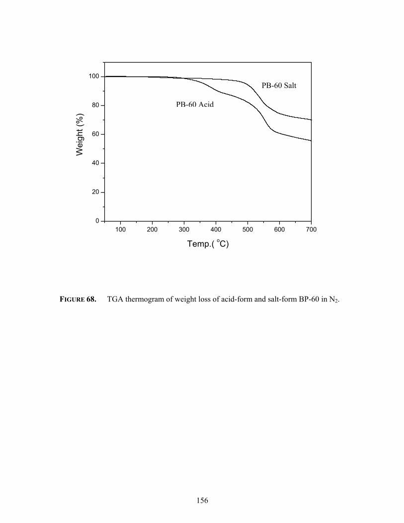
156
100 200 300 400 500 600 7000
20
40
60
80
100W
eigh
t (%
)
Temp.( oC)
FIGURE 68. TGA thermogram of weight loss of acid-form and salt-form BP-60 in N2.
PB-60 Acid
PB-60 Salt

157
Membrane Characterization
3.3.5 Solution Properties
Polymer solubility is an important property and is often related to several
parameters, including the type of polymer, architecture, and, of course, the solvent. The
sulfonated poly(arylene ether sulfone) copolymers were tested for solubility in several
common solvents, include NMP, DMAc, DMSO, chloroform, and water. The
copolymers were typically examined at 10% polymer solutions (weight/volume) in each
solvent. The results are presented in Table 8.
All control and sulfonated copolymers were dissolved in NMP and DMAc when
agitated with a magnetic stirrer to yield clear, homogeneous solutions. After four weeks
the unsulfonated hydroquinone control polymer (HQ-00) solution became opaque and
eventually crystallized from the DMAc solution. No precipitation/crystallization was
observed at any other composition of the hydroquinone-based sulfonated copolymers.
The bisphenol A-based sulfonated copolymers were soluble in chloroform up to 30 mol
percent sulfonated dihalide compositions in the polymerization feed. At high degrees of
sulfonation the polymers were swollen to a gel, but did not give a true solution at 10%
concentrations.
The relatively high solubility of the sulfonated poly (arylene ether sulfone)
copolymers in common solvents agrees with the absence of branching or cross-linking
during polymerization.

158
Table 8. Influence of bisphenol structure and degree of sulfonation on sulfonated
poly (arylene ether sulfone) copolymers solubility behavior in common
solvents (10% wt/vol) at room temperature.
Polymer NMP DMAc DMSO Water Chloroform
Bis A-30 Y Y Y SW Y
Bis A-40 Y Y Y SW SW
Bis A-50 Y Y Y SW SW
Bis A-60 Y Y Y SW SW
BP-30 Y Y Y SW N
BP-40 Y Y Y SW N
BP-50 Y Y Y SW N
BP-60 Y Y Y SW N
6F-30 Y Y Y SW SW
6F-40 Y Y Y SW N
6F-50 Y Y Y SW N
6F-60 Y Y Y SW N
HQ-30 Y Y Y SW N
HQ-40 Y Y Y SW N
HQ-50 Y Y Y SW N
HQ-60 Y Y Y SW N
Y ≡ solubale; SW ≡ swells; N ≡ insoluble, not swelling
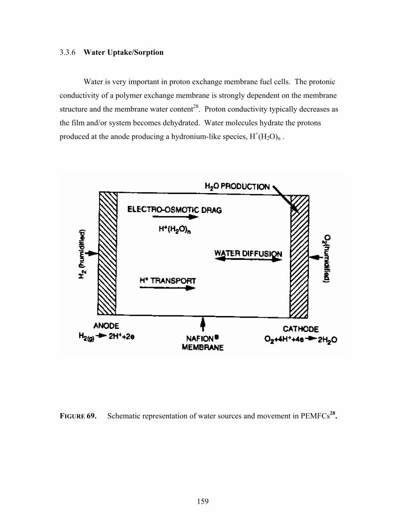
159
3.3.6 Water Uptake/Sorption
Water is very important in proton exchange membrane fuel cells. The protonic
conductivity of a polymer exchange membrane is strongly dependent on the membrane
structure and the membrane water content28. Proton conductivity typically decreases as
the film and/or system becomes dehydrated. Water molecules hydrate the protons
produced at the anode producing a hydronium-like species, H+(H2O)n .
FIGURE 69. Schematic representation of water sources and movement in PEMFCs28.

160
Proper water management is vital to proper operation and performance of
PEMFCs. As depicted in Figure 69, there exists a complex system involving water
management in proton exchange membrane fuel cells. Beyond the use of humidified
gases28, many researchers have proposed ways to keep the PEMFC system
hydrated314,315,316,317,318, especially at the anode. The electro-osmotic drag of water from
the anode to the cathode tends to dry out the anode. Even though there will be some
back-diffusion of water towards the anode, water accumulates at the cathode and may
cause “flooding” and a loss of performance. One approach that has been described to re-
introduce water at the anode is inserting a wet wick into the cell that allows water to drip
onto the proton exchange membrane315. Alternatively, Cisar et al. introduced small,
circular channels or “tubes” into the PEM into which water is pumped to the system316.
The largest amount of water is introduced in the fuel cell during the treatment and
hydration of the PEM. Preconditioning of the proton exchange membranes in purified
water is a customary practice. The films are hydrated before being placed into the fuel
cell. The importance of the polymer treatment and handling has been demonstrated319,320.
Water uptake or the level of hydration may be a function of a number parameters.
Among the possible parameters are the types of polymer, temperature, and time required
to reach an equilibrium state within the film.
The water uptake for the sulfonated poly(arylene ether sulfone) copolymers
synthesized in this research was determined, as weight percent, by the following
equation:
water uptake = %100×−
dry
drywet
WWW
Eqn 17
314 Wilson, M.S.;Zawodzinski, C.; Gottesfeld, S., Proceedings Abstracts at The 1998 Fuel Cell Seminar, Palm Springs, California,
November 1998, p. 651. 315 Watanabe, M.; Satoh, Y.; Shimura, C., J. Electrochem. Soc., 1993, 140, 3190. 316 Cisar, A.J.; Gonzalez-Martin, A.; Hitchens, G.D.; Murphy, O.J., US Patent 5,635,039, 1997. 317 Wilson, M.S. ; Zawodzinski, C.; Gottesfeld, S., in in Proton Conducting Membrane Fuel Cells: 2nd International Symposium,
1998, Electrochem. Soc. Proceedings Series, 98, 27. 318 Wood III, D.L.; Yi, J.S.; Nguyen, T.V., Electrochim. Acta 1998, 43 (24), 3795. 319 Zawodzinski, T.; Derouin, C.; Radzinski, S.; Sherman, R. J.; Smith, V. T.; Springer, T. E.; Gottesfeld, S. J. Electrochem. Soc.
1993, 140, 1041.

161
where Wwet and Wdry are the equilibrium weights of the wet and dry membranes,
respectively. The equilibrium weight was taken as the weight at which no further change
in weight was observed. The equilibrium dry weight was determined using an analytical
balance after thoroughly drying the acid-form films at 120 oC and the salt-form of the
films at 150 oC. The equilibrium sorption was typically achieved after 40 to 70 hours of
soaking in deionized water.
The sulfonated poly (arylene ether sulfone) copolymers showed increasing water
uptake with increasing degree of sulfonation. Other researchers obtained similar
results321,322. The results are tabulated on Table 9. Beyond the increase in water sorption
along any copolymer series as a function of the degree of sulfonation, a dependence on
the bisphenol was observed. The water sorptions in the acid-form films of the sulfonated
copolymers were tested and showed generally higher water uptake than the
corresponding salt-form.
Table 9. Influence of the degree of sulfonation and the bisphenol structure on the
water uptake of sulfonated poly(arylene ether sulfone) copolymers at
30oC acidified in 1.5 M sulfuric acid (24 hours, 30 oC) followed by
soaking for 24 hours in deionized water.
Mol Percent of Disulfonated Halide Monomer
Bisphenol 0 10 20 30 40 50 60
Bis A 3 7 13 25 37 48 68
BP 2 5 10 18 28 38 65
6F 2 5 9 13 25 34 42
HQ 2 7 23 31 50 68 >140
320 Bunce, N.; Sondheimer, S.; Fyfe, C. A. Macromolecules 1986, 19, 333. 321 Zaidi, S.M.J.; Mikhailenko, S.D.; Robertson, G.P.; Guiver, M.D.; Kaliaguine, S., J. Membr. Sci., 2000, 173, 17. 322 Leung, L.; Bailly, C..; O’Gara, J.F.; Williams, D.J.; Karasz, F.E.; MacKnight, W.G., Polym. Commun., 1987, 28, 20.

162
While copolymers formed from bisphenol A and biphenol displayed similar water
uptakes, hydroquinone based copolymers sorbed higher amounts of water at comparable
degrees of sulfonation. In contrast, 6F bisphenol A based sulfonated copolymers
displayed lower levels of water uptake at corresponding degrees of sulfonation. The
hydrophobic nature of the fluorines in the 6F bisphenol A structure apparently makes the
copolymers less hydrophilic than other sulfonated copolymers. No analogous
generalization can easily explain the higher water uptake of the hydroquinone
copolymers, except it has the lowest molar mass. Hydroquinone is structurally very
similar to biphenol and similar water sorption(s) were expected. One possible
explanation for the differences in water uptake may be found in the microstructure of the
membrane of the copolymers and will be discussed later.
An optimum degree of sulfonation needs to be established for producing the PEM
with the “best” performance. While higher levels of sulfonation will provide higher
proton conductivity, other membrane properties may suffer. A membrane that is too
hydrophilic would swell greatly yielding a hydrogel and may be weak and not efficiently
serve as a barrier for the fuel and oxidizer. Furthermore, undesirable stress by the
swollen membrane may be placed on the fuel cell hardware. As shown in Table 9, at
between the 50 and 60 percent disulfonation levels very high water uptake levels (>180
weight percent) for bisphenol A and biphenol based copolymers were observed. A
similarly high increase in water uptake is observed for hydroquinone copolymers
between 40 and 50 percent disulfonation. The change causes at least a two-fold increase
in water sorption after short term (~24 hours) soaking. At these levels of hydration the
copolymers are essentially hydrogels and have little structural (i.e., mechanical) stability.
6F bisphenol A copolymers sorb less water and still maintain a good structural / film
behavior.
Similar nonlinear or abruptly large water sorptions have been observed in several
post-sulfonated sulfonated copolymers, including polysulfones108,323 and polyketones129.
Not surprisingly, increased temperature increased the water uptake of the
sulfonated poly (arylene ether sulfone) copolymers. Nolte et al.108 and Kerres et al.126
323 Arnold, C.; Assink, R.A., J. Membr. Sci. 1988, 38, 71.

163
have shown that some of their post-sulfonated poly (arylene ether sulfones) were soluble
in water at elevated temperatures (above 60 oC) unless some (controlled) degree of cross-
linking reaction was performed. Films of the directly sulfonated copolymers synthesized
in the present research were evaluated for their water uptake at 80 oC for 48 hours. The
results, shown in Table 10, indicated a typically 30 wt% higher water uptake at 80 oC
compared to 30 oC.
Table 10. Influence of the degree of sulfonation and the bisphenol structure on the
water uptake of selected salt-form compositions of sulfonated poly
(arylene ether sulfone) copolymers at 80 oC.
mol% SDCDPS
Polymer 20 30 40 50
Bis A 27 45 75 >200
BP 25 40 64 >200
6F 18 30 55 100
HQ 35 80 >300 hydrogel
Several researchers have investigated the water uptake of perfluorinated sulfonic
acid copolymers324,325. The correlation between water content and conductivity was
reaffirmed. Interestingly, an interdependence between the treatment of Nafion and water
content was observed by Bunce et al.326. It was shown that the water uptake after
different drying conditions changed the amount of water Nafion films re-absorbed.
324 (a)Yeo, R. S. J. Electrochem. Soc. 1983, 130, 533; (b) Pourcelly, G.; Oikonomou, A.; Hurwitz, H. D.; Gavach, C. J. Electroanal.
Soc. 1990, 287, 43; (c) Randin, J. J. Electrochem. Soc. 1982, 129, 1215. 325 Zawodzinski, T.; Derouin, C.; Radzinski, S.; Sherman, R. J.; Smith, V. T.; Springer, T. E.; Gottesfeld, S. J. Electrochem. Soc.
1993, 140, 1041. 326 Bunce, N.; Sondheimer, S.; Fyfe, C. A. Macromolecules 1986, 19, 333.

164
Nafion films that were dried under vacuum at room temperature absorbed more water
than films dried at temperatures over 100 °C in a vacuum oven.
Similar analysis for the biphenol-based sulfonated poly(arylene ether sulfone)
copolymer series was conducted. For this experiment salt forms films were cast on glass
substrates and dried using only infrared lamp heating (~70 oC) in a nitrogen purge. These
films were weighed and submerged in deionized water at 30 oC for 48 hours. The results
are tabulated in Table 11. In comparison to films dried in a vacuum oven (Table 8) the
biphenol-based sulfonated copolymers sorbed up to 40 wt% more water.
Table 11. Influence of the infrared lamp-drying on water uptake in salt-form of
biphenol-based sulfonated poly (arylene ether sulfone) copolymer
membranes at 30 oC.
BP-20 BP-30 BP-40 BP-50 BP-60
18 27 38 56 130
One possible explanation for the different water uptakes may be the organization
of the ionic clusters/aggregates. During normal 150 oC drying of the salt-form copolymer
films trace solvent and/or water may allow some mobility of the polymer chains causing
the production of different size aggregates. The drying temperature of the infrared lamp
(~80 oC) is considerably less that the copolymers Tg and, therefore, may not allow the
same chain mobility. Comparable discussions have been given by Eisenberg57, 327 and
others55,60 on the formation of ionomer clusters. Among many elements, ionic
interactions and polymer elasticity are important factors involved in cluster formation.
The different sized clusters may sorb different quantities of water. A different
acidification method (Method 2) was developed and its influence on several properties,
including water uptake will be discussed in Section 3.3.9.
327 Eisenberg, A. Macromolecules 1970, 3, 147.

165
3.3.7 Proton Conductivity
From an application point-of-view, good protonic conductivity of a proton
exchange membrane is clearly one of the most important properties. The magnitude of
the specific conductivity is determined by a combination of charge carrier density and
the charge carrier mobility28. The charge carrier is, of course, the proton and is
dependent, to some extent, on the number of pendent sulfonic acid groups along the
polymer chain.
There are other factors that influence the overall proton conductivity. As noted
earlier, the film thickness was important as exemplified by Dow’s thin (2 mils)
perfluorosulfonic acid proton exchange membrane. The importance of water (and water
uptake in the PEM) on proton conductivity has already been discussed.
Proton conductivity was measured on solution cast films of all the sulfonated poly
(arylene ether sulfone) copolymers synthesized in this research. The conductivities were,
of course, measured in the acidified form of the sulfonated copolymers. The conversion
of the sodium salt membranes to their respective free acid membrane has been the subject
of several studies. Kim et al.328 have recently shown the influence on proton conductivity
of the acidification treatment of biphenol-based sulfonated poly (arylene ether sulfone)
copolymers. Higher proton conductivities were measured for fully submerged/hydrate
membranes that were treated with boiling 0.5M sulfuric acid for 1 hour than for
membranes that were converted in 0.5M sulfuric acid for 24 hours at room temperature.
Titration and NMR experiments were conducted to verify that no additional sulfonation
occurred during the boiling treatment. A change in morphology was proposed as the
cause of the increase in proton conductivity. Further discussions on morphology will be
presented in a later section.
An extremely important factor on proton conductivity was found to be the
conditions under which the measurements were made. Proton conductivities have been
reported on most of the PEM candidates outlined in Chapter I. The conductivities were
determined for fully hydrated (immersed) films, films at different humidity levels, films
328 Kim, Y.S; Wang, F.; Hickner, M.; McCartney, S.; Hong, Y. T.; Harrison, W.; Zawodzinski, T.A.; McGrath, J.E.,. J.Poly Sci:
Physics, 2002, in press (b) ibid., The Electrochemical Society 201st Meeting, Philadelphia, PA, May 12-17, 2002, Abstr.# 182.

166
at different temperatures, films with various additives / dopants, etc. It is well known the
temperature influences the proton conductivity. Furthermore, the analyzing cell’s
configuration should also be noted. Most proton conductivities are measured using either
a 2-point or 4-point probe. The advantage of one probe over the other is still debatable,
but the 4-point probe is commonly used for anisotropic materials.
Proton conductivities of the fully hydrated acid-form sulfonated poly(arylene
ether sulfone) copolymers were performed at 30 oC using a Solatron 1260 Impedance
instrument. The 2-point analyzer is shown below. Actually, the resistance, R, (units of
ohm) of each copolymer membrane was determined and then the reciprocal was taken to
determine the proton conductance, ∂, (units of Siemens/cm). The equation employed for
the conductivity determination is also given below. The proton conductivity results are
given in Tables 12A-D. The ion exchange capacity of each polymer is displayed in the
tables. Recall the ion exchange capacity is the average number of sulfonic acid groups
per unit mass of polymer (milli-equivalents/gram).
1
2
3
4 5
6
Legend 1. Teflon block 2. Thumbscrew 3. Open area to allow
equilibration with environment 4. Membrane sample 5. Blackened Pt foil electrode 6. Pt lead
∂ = 1 l . R A Where ∂ = conductivity (S/cm) R = resistance (ohms) l = length between electrodes (cm) A = cross-sectional area of film (cm2)

167
As expected, the unsulfonated control polymer membranes, which have an ion exchange
capacity of zero, showed no measurable proton conductivities. Along each copolymer
series, the proton conductivity increased with increasing ion exchange capacity. For each
comparable degree of disulfonation the hydroquinone based sulfonated copolymers had
the highest exchange capacity. This was expected since the formula weight of the repeat
unit for the hydroquinone copolymers is smaller than the repeat units of the other
copolymers. The hydroquinone-based sulfonated copolymers also showed higher proton
conductivity. Films of the hydroquinone copolymer that contained 60 mol% sulfonated
dihalide sulfone comonomer (HQ-60) had excessive water uptake and, therefore, were
not submitted for proton conductivity measurements.
The 6F bisphenol A based sulfonated copolymers (6F-XX) showed high proton
conductivity even though their respective water uptakes were lower than those of the
other sulfonated copolymers. The conductivities of the 6F sulfonated copolymers were
lower than those of the other copolymers with comparable levels of sulfonation; this may
be related to their lower water content. However, the measured values are still at least an
order of magnitude higher than the conductivities typically reported for sulfonated
polymers206 prepared by some post-sulfonating reactions.
Closer examination of the data across the different bisphenol structures revealed
that at similar ion exchange capacities the proton conductivity is essentially the same.
For example, an IEC value of approximately 2 meq/g corresponded to a proton
conductivity of all the various sulfonated copolymers of approximately 0.10 S/cm. This
revelation should be expected but has not been highlighted or reported by others,
which is probably due to difficulties in the control of polymer post-sulfonation
reactions and the lack of a systematic study.

168
Table 12A. Influence of Degree of Sulfonation on Several Features of Bisphenol A
based Copolymers
XX, mol% SDCDPS
Degree of Sulfonation by 1H NMR
[η]NMP IEC#, meq/g Conductivity (S/cm), 30oC,
Method 1 acidification
0 - 0.70 0 -
10 12 0.78 0.41 0.01
20 18 0.82 0.79 0.03
30 31 1.20 1.12 0.06
40 37 1.86 1.58 0.08
50 48 2.48
2.75*
1.78 0.11
60 56 2.80
3.08*
2.13 0.17
* Copolymerization using DFDPS/SDFDPS system.
# Determined from non-aqueous potentiometric titration.
yX
SO3HHO 3S
S
O
OCH3
CH3
O O S O
O
O
CH3
CH3
O

169
Table 12B. Influence of Degree of Sulfonation on Several Features of Biphenol based
Copolymers
XX, mol% SDCDPS
Degree of Sulfonation by 1H NMR
[η]NMP IEC, meq/g Conductivity (S/cm), 30oC,
Method 1 acidification
0 - 0.65 0 -
10 8 0.70 0.41 0.009
20 23 0.93 0.89 0.03
30 31 1.51 1.31 0.05
40 40 1.82 1.51 0.09
50 49 2.09
2.52*
1.98 0.11
60 58 2.69
2.94*
2.22 0.16
* Copolymerization using DFDPS/SDFDPS system.
# Determined from non-aqueous potentiometric titration
O O SO
OO O S
O
OHO3S SO3H

170
Table 12C. Influence of Degree of Sulfonation on Several Features of 6F Bisphenol A
based Copolymers
XX, mol% SDCDPS
Degree of Sulfonation by 1H NMR
[η]NMP IEC#, meq/g Conductivity (S/cm), 30oC,
Method 1 acidification
0 - 0.59 0 -
10 9 0.69 0.32 0.005
20 19 0.86 0.59 0.008
30 27 1.49 0.87 0.02
40 41 1.70 1.16 0.06
50 52 2.01
2.42*
1.50 0.08
60 58 2.07
2.53*
1.77 0.10
* Copolymerization using DFDPS/SDFDPS system.
# Determined from non-aqueous potentiometric titration.
CF3
CF3
O O S O
O
O
CF3
CF3
O S
O
OHO 3S SO3H
Xy

171
Table 12D. Influence of Degree of Sulfonation on Several Features of Hydroquinone
based Copolymers
XX, mol% SDCDPS
Degree of Sulfonation by 1H NMR
[η]NMP IEC#, meq/g Conductivity (S/cm), 30oC,
Method 1 acidification
0 - 0.89 0 -
10 13 0.86 0.60 0.03
20 18 1.20 1.00 0.06
30 32 1.82 1.58 0.08
40 38 2.29 1.94 0.11
50 46 2.37
2.65*
2.48 0.13
60 55 2.41
2.88*
2.77 N/D
* Copolymerization using DFDPS/SDFDPS system.
# Determined from non-aqueous potentiometric titration
1-xxO O S O O S
O
O O
O
SO3HHO3S

172
3.3.8 Morphology
The solid state organization that develops within various copolymers may give
rise to distinct regions that define that copolymer’s morphology. Block and semi-
crystalline polymers are often studied for their morphology and the properties invoked by
morphology variations329. Many elastomeric-type ionomers have also shown distinct
morphologies. Phase separation and clustering of the ionic moieties from the bulk
polymer present a different type of morphology. The size of the new ionic domains is
typically reported in the sub-micron (nanometer) scale. The sizes of the clusters are
influenced by a number of factors93,94,95,328, 330,331, including the number of ion groups,
semicrystallinity, amount of hydration, and the treatment (i.e., drying, acidification,
solvent, etc.) to the polymer.
The influence of the bisphenol structure on the morphology and on thee clustering
of the sulfonate groups was investigated. Bisphenol A and 6F bisphenol A are
structurally similar but the 6F bisphenol is much more hydrophobic. Biphenol and
hydroquinone add more rigidity to the polymer system. Tapping-mode atomic force
microscopy (TM-AFM) was employed to explore the morphological characteristics of the
four series of sulfonated copolymers. Tapping mode phase imaging is a comparatively
new atomic force microscopy technique332. TM-AFM is powerful because it can
distinguish areas with different properties (eg. hardness, etc.) regardless of their
topographical nature 330,333,334.
Phase images of the directly sulfonated poly(arylene ether sulfone) copolymers
were recorded to investigate the ionic clustering under ambient conditions. The
sulfonated copolymers were thoroughly dried under vacuum to remove water, etc. from
the thin film samples. All four control (unsulfonated) polymers showed no
329 (a) Noshay, A.; McGrath, J. E. Block Copolymers: Overview and Critical Survey; Academic Press: New York, 1977; (b) Aggarwal,
S. L. Block Copolymers; Plenum: New York, 1970. 330 Zawodzinski, T.; Derouin, C.; Radzinski, S.; Sherman, R. J.; Smith, V. T.; Springer, T. E.; Gottesfeld, S. J. Electrochem. Soc.
1993, 140, 1041. 331 James, P.J.; McMaster, T. J.; Newton, J. M.; Miles, M. J., Polymer 2000, 41, 4223. 332 Binnig, G.; Quate, C. F.; Gerber, C., Phys Rev Lett 1986, 56, 930. 333 Tamayo, J.; Garcia, R., Langmuir 1996, 12, 4431. 334 Howard, A. J.; Rye, R. R.; Houston, J. E., J Appl Phys 1996, 79, 1885.

173
distinguishable features. Distinct dark phases/regions are observed for the sulfonated
copolymers. These dark regions are attributed to the clustering of the softer pendant
sulfonic acid groups (which contain some water) and are organized on the size scale of
~7-25 nm. The dampening effects in the hydrated ionic groups are presented as dark
domains in phase contrast mode. Sample micrographs on the 4,4’-biphenol based series
from TM-AFM are shown in Figure 70.
FIGURE 70. TAPPING MODE-AFM MICROGRAPH OF ACID-FORM BIPHENOL-BASED
SULFONATED POLY (ARYLENE ETHER SULFONE) COPOLYMERS167. SCAN
BOXES ARE 700 X 700 NM FOR EACH PLOT.
BPSH(0) BPSH(20)
BPSH(40) BPSH(50) BPSH(60)
• Scale: 700 nm• Phase angle: 30 degree

174
The aggregate size and connectivity (“co-continuous phase”) was shown within a
copolymer series to be dependent upon the degree of disulfonation. For example BP-20
has an aggregate domain size of ~10 to 15 nm in diameter, while BP-40 aggregates were
~20-25 nm in diameter. The BP-40 clusters were elongated, yet defined and separated.
However, BP-60 demonstrated connected aggregates representing a new morphology.
Many of these connected domains were greater than 100 nm in length. The continuous
domains may parallel the “channels” (4-10 nm) observed97,335 in Nafion 117 under
ambient conditions. The channel formation is likely the source of the very high water
uptakes observed in the hydrogel-like, hydrophilic continuous BPSH-60 reported earlier
in Table 11 and depicted in the above AFM micrographs.
An influence was also attributed to the bisphenol structure. The aggregates of
hydroquinone based sulfonated copolymer were consistently larger than those of other
sulfonated copolymers of comparable degrees of sulfonation. On the other hand, the 6F-
based sulfonated copolymers showed smaller aggregated domains (Figure 71). The 6F-
60 displayed separated ionic domains, similar to those observed in BP-40 AFM
micrographs. These differences in domain sizes and connectivity may have an influence
of the observed contrast in water uptake behavior of the copolymers within and across the
four copolymer series.
335 R.S. McLean, M.Doyle, B.B. Sauer, Macromolecules 2000, 33, 6541.

175
(a)
(b)
FIGURE 71. Tapping mode –AFM phase image of 6F sulfonated copolymers (a) 6FSH-
50 and (b) 6FSH-60. The micrographs are 700 x 700 nm windows with
phase angle scales of 0-30 o.
6FSH-50
6FSH-60

176
Copolymer post-treatment has also shown an influence on a number of properties.
Here, the term post-treatment encompasses how the sulfonated copolymer films were
converted from their salt forms into their respective acid forms. The influence of drying
conditions on water uptake of biphenol-based copolymers was demonstrated in Section
3.3.6 (see Tables 9 and 11). An alternative film- acidification procedure to the 30 oC in
1.5 M sulfuric acid (“Method 1”) is immersion in 0.5 M boiling (~ 100 oC) sulfuric acid
solution for 2 hours followed by immersion in boiling deionized water for 2 hours
(“Method 2”). Method 2 is obviously a more aggressive acidification procedure and has
been shown to influence several properties. Table 13A-C tabulates water uptake and
conductivity values of Method 1 and Method 2 post-treatments for selected copolymers.
Table 13A Influence of acidification method on water uptake and conductivity of
select bisphenolA-based sulfonated poly (arylene ether sulfone)
copolymers
Water Uptake (wt%) Conductivity (S/cm)
Dihalide mol% Method 1 Method 2 Method 1 Method 2
Bis A-20 13 20 0.03 0.04
Bis A-30 25 40 0.06 0.08
Bis A-40 37 68 0.08 0.10

177
Table 13B Influence of acidification method on water uptake and conductivity of
select biphenol-based sulfonated poly (arylene ether sulfone) copolymers
Water Uptake (wt%) Conductivity (S/cm)
Dihalide mol% Method 1 Method 2 Method 1 Method 2
BP-20 10 17 0.03 0.04
BP-30 18 31 0.05 0.06
BP-40 28 58 0.09 0.10
Table 13C Influence of acidification method on water uptake and conductivity of
select 6F bisphenol A-based sulfonated poly (arylene ether sulfone)
copolymers
Water Uptake (wt%) Conductivity (S/cm)
Dihalide mol% Method 1 Method 2 Method 1 Method 2
6F-20 9 15 0.008 0.01
6F-30 13 23 0.02 0.03
6F-40 25 54 0.06 0.08
Each sulfonated copolymer displayed higher water uptake and proton
conductivity after Method 2 acidification compared to Method 1 acidification. The
boiling conditions in Method 2 caused a morphological change within the copolymers, as
observed by subsequent TM-AFM microscopy328. The higher proton conductivity with
increased water uptake of Method 2 films agrees with earlier noted326 trends.
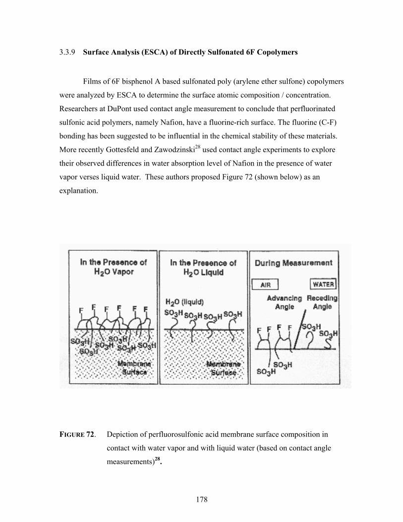
178
3.3.9 Surface Analysis (ESCA) of Directly Sulfonated 6F Copolymers
Films of 6F bisphenol A based sulfonated poly (arylene ether sulfone) copolymers
were analyzed by ESCA to determine the surface atomic composition / concentration.
Researchers at DuPont used contact angle measurement to conclude that perfluorinated
sulfonic acid polymers, namely Nafion, have a fluorine-rich surface. The fluorine (C-F)
bonding has been suggested to be influential in the chemical stability of these materials.
More recently Gottesfeld and Zawodzinski28 used contact angle experiments to explore
their observed differences in water absorption level of Nafion in the presence of water
vapor verses liquid water. These authors proposed Figure 72 (shown below) as an
explanation.
FIGURE 72. Depiction of perfluorosulfonic acid membrane surface composition in
contact with water vapor and with liquid water (based on contact angle
measurements)28.

179
As shown a fluorine-rich surface covers the film in the high humidity / water
vapor environment. However when the Nafion film was submerged in liquid water
sulfonic acid groups dominated the surface, after some elapsed time. This surface
change, from hydrophobic fluorine to hydrophilic sulfonic acid, appeared to be a natural
adjustment for the elastomeric polymer since no additional treatment was applied on the
film.
The 6F-based poly(arylene ether sulfone) copolymers showed a relatively high
surface fluorine content. Electron Spectroscopy for Chemical Analysis (ESCA) data are
shown in Table 14. The films were evaluated in both the salt and acidified forms.
Furthermore, the influence of Method 1 and Method 2 was explored.
Table 14 Influence of the degree of disulfonation in 6F-based poly(arylene ether
sulfone) copolymers and acidification treatment on the fluorine surface
content* as determined by ESCA. (%Fluorine).
Degree of Sulfonation
Treatment↓ 0 40 50 60
Theoretical 21 18.3 18.0 17.6
Salt 0.6 0.8 0.9 4.3
Method 1 N/A 6.5 8.0 9.2
Method 2 N/A 12 12.5 13.4
* Only the air side of the films was evaluated.
N/A means not available (i.e., not analyzed)
180
The surface fluorine contents of the sulfonated copolymer films increased with
increasing degree of sulfonation, but were all lower than the theoretical values based on
structural formula / composition. Furthermore, post-treatment does influence the films’
surface composition. Interestingly, the acidified films regardless of post-treatment had
significantly higher fluorine concentration on the film surface than did the comparable
salt-form film, suggesting higher self-assembly. It must be noted that the high vacuum
ESCA analysis required well dried films and therefore only indirect comparisons can be
inferred between Nafion and the 6F sulfonated copolymers. Further experimentation,
such as surface contact angles, is suggested so that wet films may be examined and direct
comparisons can be made accordingly. Nevertheless, these results do suggest some self-
assembly of the film surface as a function of both the degrees of sulfonation and film
post-treatment, which may be important in the oxidative stability of the membrane in a
fuel cell.

181
FIGURE 73. ESCA SURVEY SCAN OF THE SURFACE ATOMIC COMPOSITION OF 6F-50
ACIDIFIED FILM.

182
CHAPTER 4
Journal of Polymer Science Publication
Influence of Bisphenol Structure on the Direct Synthesis of Sulfonated Poly(arylene
ether) Copolymers. I
William L. Harrison, Feng Wang1, Jeffery B. Mecham2, Yu Seung Kim, Melinda Hill and
James E. McGrath*
Department of Chemistry and Materials Research Institute
Virginia Polytechnic Institute and State University
Blacksburg, VA 24061, USA
*To whom correspondence should be addressed: [email protected] 1 Present address: PPG Industries, R & D Center, Monroeville, PA 2 Present address: Nanosonic, Blacksburg, VA

183
ABSTRACT: New sulfonated poly(arylene ether sulfone) copolymers have been
successfully synthesized in high molecular weight with controlled degrees of
disulfonation up to 70 mol% via direct copolymerization of sulfonated aromatic
dihalides, aromatic dihalides, and one of four structurally distinct bisphenols. The wholly
aromatic acid form proton conducting copolymers are of interest as proton exchange
membranes (PEM) for fuel cells. The disodium salts of 3,3’-disulfonated-4,4’-
dichlorodiphenyl sulfone and 3,3’-disulfonated-4,4’-difluorodiphenyl sulfone
comonomers were synthesized via sulfonation of 4,4’-dichlorodiphenyl sulfone or 4,4’-
difluorodiphenyl sulfone with 30% fuming sulfuric acid at 110 oC. Four bisphenols
(4,4’-bisphenol A, 4,4’-bisphenol AF, 4,4’-biphenol, and hydroquinone) were
investigated for the syntheses of novel copolymers with controlled degrees of sulfonation.
The composition and incorporation of the sulfonated repeat unit into the copolymer were
confirmed by 1H NMR and Fourier transform infrared spectroscopy (FTIR). Solubility
tests on the sulfonated copolymers confirm that no cross-linking and probably no
branching occurred during the copolymerizations. Tough, ductile films could be solvent
cast and exhibited increased water absorption with increasing degrees of sulfonation.
These copolymers are promising candidates for high temperature proton exchange
membranes in fuel cells which will be reported separately in a forthcoming paper.
Key Words: sulfonated activated halide monomers, direct copolymerizations, proton
exchange membranes, fuel cells, polyether sulfones, bisphenol structures.

184
Introduction
Poly(arylene ether sulfones) are engineering thermoplastics which are well-known
since the pioneering studies of R. N. Johnson and A. G. Farnham et. al to have excellent
mechanical and chemical properties 1-3. They are utilized as films, coatings, membranes
in ultrafiltration systems, gas separators, and other high performance molded and/or
extruded applications4. Chemical modifications of polymers can be employed to tailor
properties of many materials. Post-sulfonations of aromatic rings5,6 is one example of an
electrophilic aromatic substitution reactions which can be exploited for increasing the
hydrophilicity of poly(arylene ether sulfone)s.
Post- sulfonation of poly (arylene ether sulfone)s has been accomplished with
various sulfonating agents. Chlorosulfonic acid was perhaps the earliest reported
sulfonation agent for poly(arylene ether sulfone)s7. Many researchers have further
investigated this methodology for poly(arylene ether sulfone)s8-10 as well as for other aryl
containing polymers11,12. However, undesirable chain scission, particularly with
isopropylidene units (Bisphenol A), branching and/or cross-linking can occur using
chlorosulfonic acid6. There are reports of decreased intrinsic viscosity and insolubility
(partial gelation), and the inability to produce coherent films after modification.
Sulfonation with sulfuric acid has also been demonstrated for many aromatic
1
O
CH3
CH3
O S
O
O
n

185
polymers13-15. Noshay and Robeson5 introduced a mild sulfonation procedure in which a
complex of sulfur trioxide and triethyl phosphate was used to sulfonate commercially
bisphenol A based poly(arylene ether sulfone), Udel (1), as shown in Scheme 1 B. C.
Johnson et al.6 utilized this route to prepare materials intended for applications as
desalination membranes. While the milder sulfur trioxide-triethyl phosphate complex
produces materials devoid of side reactions, the procedure requires careful handling and
preparation and generally is limited to only one sulfonate per activated unit. An
interesting, but somewhat lengthy sulfonation process involving lithiating Udel with n-
butyllithium at low temperatures, sulfinating the metallated aromatic ring using sulfur
dioxide, and finally oxidizing to afford the modified sulfonated poly(arylene ether
sulfone) was demonstrated by Kerres16.
In our experience, only modest control and reproducibility over the sequence
lengths of sulfonated units is afforded by post-sulfonation procedures. Accordingly,
several groups17,18, including our own19-22 have explored monomer sulfonations and
subsequent controlled copolymerization. Matzner and Robeson demonstrated the
sulfonation of 4,4’-dichlorodiphenyl sulfone (DCDPS) 23 for the purposes of producing
more fire resistant polyarylates . Ueda et al.24 copolymerized 3,3’-disulfonated-4,4'-
dichlorodiphenyl sulfone, 4,4’-dichlorodiphenyl sulfone, and bisphenol A to generate
copolymers utilizing up to 30 mole percent of the disulfonated monomer, although
relatively little characterization was provided. One may argue that this approach allows
for much better control of the position and degree of sulfonation of poly(arylene ether
sulfones).
186
Current interest involves the synthesis of potentially economical, commercially
viable and highly thermo-oxidatively stable engineering polymers as candidates for
proton exchange membranes in fuel cells (PEMFCs). Fuel cells are attractive alternative
energy devices that convert chemical energy directly into electrical energy by a series of
platinum catalyzed reactions25. The proton exchange membrane (PEM) should minimize
mixing of the reactant gases and also serve as an electrolyte, permitting proton
conduction from the anode to the cathode. Perfluorinated copolymers, such as Nafion
(DuPont), are the current fuel cell PEM materials of choice. These are good proton
conductors and are very stable chemically. Conversely, perfluorinated copolymers have
several limitations, some of which include (a) low moduli as well as modest Tg values;
(b) reduced conductivity at temperatures above 80 oC; and (c) relatively high methanol
permeability, which limits efficient application for direct methanol fuel cells. They are
also recognized to be currently quite expensive.
Systematic results derived by copolymerizing four different bisphenols with 3,3’-
disulfonated-4,4’-dichlorodiphenyl sulfone (SDCDPS) or 3,3’-disulfonated-4,4’-
difluorodiphenyl sulfone(SDFDPS) and their respective parent compounds are presented
in this paper. The chemical structures of the bisphenols were selected to investigate
anticipated differences in thermo-oxidative and hydrolytic stability, as well as
hydrophilicity in the resultant copolymers. The isopropylidene link in the bisphenol A
unit could be unstable at elevated temperatures under the strongly acidic PEM fuel cell
conditions and the oxidative stability may also be an issue. Bisphenol A (BA) and 6F-
bisphenol A (6FBA) produced flexible film forming materials, but have distinct
187
differences in hydrophilicity as judged by water swelling and subsequent photoelectron
spectroscopy (XPS) measurements. Biphenol (BP) and hydroquinone (HQ) afforded
more rigid (i.e., higher Tg), wholly aromatic copolymers. The results may be compared
with our earlier reports which were primarily focused on 4,4’-biphenol systems22,26.
Moreover, the influences of the varying reactivities of the bisphenols on the conditions
required for syntheses of high molecular weight sulfonated poly(arylene ether sulfone)
copolymers with controlled degrees of sulfonation have also been explored.
Experimental
Reagents: 4,4'-Isopropylidenediphenol (Bisphenol A, Bis A), obtained from Dow
Chemical, was recrystallized from toluene and dried under vacuum. 4,4’-
Hexafluoroisopropylidenediphenol (Bisphenol AF or 6F Bisphenol A), received from
Ciba, was purified by sublimation and dried under vacuum. Eastman Chemical provided
high purity 4,4'-biphenol (BP) and the hydroquinone (HQ) which were dried, but
otherwise used as received. Highly purified 4,4'-dichlorodiphenyl sulfone (DCDPS) was
dried and used as received (Solvay Advanced Polymers). The specialty monomer 4,4'-
difluorodiphenyl sulfone (DFDPS) was purchased from Aldrich and recrystallized from
toluene. N-methyl-2-pyrrolidinone (NMP) (Fisher) was vacuum distilled from calcium
hydride onto molecular sieves under vacuum, then stored under nitrogen. N,N-
Dimethylacetamide (DMAc) (Fisher) was distilled under vacuum from phosphorous
pentoxide and stored over molecular sieves under nitrogen. Potassium carbonate was
vacuum-dried prior to polymerization. Toluene and sodium chloride were obtained from
Aldrich and used as received.

188
Figure 1. Bisphenol structures investigated.
Synthesis of disodium salt of 3,3’-Disulfonated-4,4’-Dichlorodiphenyl Sulfone
(SDCDPS)
An optimized procedure from previously reported approaches19,20 was developed
and utilized for the synthesis of SDCDPS from 4,4’-dichlorodiphenyl sulfone (DCDPS).
A typical procedure is as follows: DCDPS (28.7 g, 99 mmol) was dissolved in 60 mL of
30% fuming sulfuric acid (approximately a two-equivalent excess) in a 100-mL, three
necked flask equipped with a mechanical stirrer and a nitrogen inlet/outlet. The solution
was heated to 110 oC for 6 hours to produce a homogenous solution. Then it was cooled
to room temperature and dissolved into 400 mL of icewater. Next, 180 grams of sodium
chloride were added, which produced a white precipitate identified as the disodium salt of
3,3’-disulfonated-4,4’-dichlorodiphenyl sulfone. The powder was filtered, re-dissolved
HO C
CH3
CH3
OH
HO C
CF3
CF3
OH
HO OH
OHHO
Bisphenol A Bis A
6F Bisphenol A6F
BiphenolBP
HydroquinoneHQ

189
in 400 mL of deionized water and then the pH was reduced to 6~7 by adding aqueous 2N
sodium hydroxide. An excess of NaCl (~180 grams) was added to salt out the sodium
form of the disulfonated monomer. The crude product was filtered and recrystallized
from a heated mixture of alcohol (methanol or isopropanol) and deionized water (7/3,
v/v), producing fine white needle-like crystals upon cooling over night. Proton (1H)
NMR, carbon (13C) NMR, as well as fast atom bombardment mass spectroscopy were
used to confirm structure and purity of the monomer. Elemental analysis was
satisfactory assuming a dihydrate was formed as suggested earlier22: Calcd.: C, 27.3; H,
1.15; S, 18.2; Na, 8.72. Found: C, 27.4; H, 1.23; S, 19.6; Na, 9.36.; Mass spectrum: 467
Daltons (SDCDPS - Na+). No melting point was observed for this ionic compound
below 300 oC. The yield after recrystallization was 88%, based on DCDPS.

190
Figure 2. Synthesis of disodium salt of3,3’-disulfonated-4,4’-dichlorodiphenyl
sulfone (SDCDPS).
Synthesis of disodium-3,3'-disulfonated-4,4'-difluorodiphenyl sulfone (SDFDPS)
The synthesis of SDFDPS was successfully produced from 4,4’-difluorodiphenyl
sulfone using a similar procedure to that described for SDCDPS synthesis and
recrystallized from isopropanol and deionized water (5/1, v/v). SDFDPS was also
characterized using 1H and 13C NMR spectroscopy and the atomic composition was
confirmed with elemental analysis. Recrystallized yield: 70%.
Note: prior to copolymerization, SDCDPS and SDFDPS were dried at
temperatures up to 130 oC under vacuum for at least 24 hours before use to remove water.
S
O
O
Cl Cl + SO3/H2SO4
110 oC, 6 Hours
S
O
O
Cl Cl
HO3S SO3H
S
O
O
Cl Cl
NaO3S SO3Na
Deionized H2O, 0-25 oC, NaCl2N NaOH, NaCl

191
Care must be taken when weighing this hydroscopic monomer, to achieve desired
stoichiometries.
A practical nomenclature for the copolymers described in this manuscript will be
as follows. Four different bisphenols and various ratios of disulfonated dihalide to non-
sulfonated dihalide were employed, we will herein use X-YY symbolism, where X refers
to the bisphenol and YY is the mole percent of the disulfonated dihalide. For example,
Bis A-20 describes the bisphenol A based disulfonated copolymer that utilized 20 mol%
3,3’-disulfonated-4,4’-dichlorodiphenyl sulfone (SDCDPS) with 80 mol% 4,4’-
dichlorodiphenyl sulfone (DCDPS).
Synthesis of Sulfonated Poly(arylene ether sulfone) Copolymers using SDCDPS via
Nucleophilic Step-Growth Copolymerization
The copolymerization procedures for the well dried monomers were similar for all
bisphenols, even though the reactivities were different. A typical copolymerization for
all sulfonated copolymers will be described using the bisphenol A-40 system. Firstly,
1.2624 g (5.5 mmol) bisphenol A, 0.9621 g (3.3 mmol) DCDPS, and 1.0806 g (2.2
mmol) SDCDPS (rapidly weighed) were added to a 3-neck flask equipped with an
overhead mechanical stirrer, nitrogen inlet and a Dean Stark trap. Potassium carbonate
(6.3 mmol, 0.88 g), and sufficient NMP (18 mL) were introduced to afford a 20% (w/v)
solids concentration. Toluene (9 mL) (usually NMP/Toluene = 2/1, v/v) was used as an
azeotroping agent. The reaction mixture was refluxed at 150 ºC for 4 hours to dehydrate
the system. The temperature was raised slowly to 190 ºC by controlled removal of the

192
toluene. The reaction was allowed to proceed for 16-35 hours, during which the solution
became very viscous. The solution was cooled to room temperature and diluted with
enough DMAc to allow easier filtering. After filtering through filter paper to remove
most of the salts, the copolymer was isolated by coagulation in stirred deionized water.
The precipitated copolymer was also washed several times with deionized water to
attempt to completely remove salts, then extracted in deionized water at 60 oC overnight.
Finally, it was vacuum dried at 120 ºC for 24 hours. Copolymers with other bisphenols
and compositions were also prepared via similar procedures. The homopolymer control
from each respective bisphenol and DCDPS were similarly recovered by simple dilution
filtration, and then precipitation in a methanol and water mixture (8/1, v/v) in Waring
blender.
Synthesis of Sulfonated Poly(arylene ether sulfone)s using SDFDPS via Nucleophilic
Step-Growth Copolymerization
Copolymerizations utilizing 4,4’-difluorodiphenyl sulfone (DFDPS) and 3,3’-
disulfonated-4,4’-difluorodiphenyl sulfone (SDFDPS) could be conducted at lower
reaction temperatures due to the well known enhanced comonomer reactivity. A typical
reaction is presented for hydroquinone-50. Hydroquinone (2.018 g, 18 mmol), DFDPS
(2.353 g, 9 mmol) and SDFDPS (4.201 g, 9 mmol) were added to a 3-neck flask equipped
with a mechanical stirrer, nitrogen inlet and Dean Stark trap. Next, 2.9 g of dried
potassium carbonate, and DMAc (43 mL) were introduced into the reaction flask.
Toluene (22 mL) was used to azeotrope water. The reaction mixture was refluxed at 150
ºC for 4 hours to dehydrate the system. Toluene was slowly removed to increase the

193
reaction temperature to 175 ºC and held constant for at least 16 hours. The viscous
reaction solution was cooled and diluted with DMAc. The disulfonated copolymer
isolation steps were similar to those previously described for DCDPS/SDCDPS
copolymerizations.
Membrane preparation
Membranes in the sodium sulfonate form were prepared by first redissolving the
copolymer in DMAc to afford 5-10% transparent solutions followed by casting onto
clean glass substrates. The films were carefully dried with infrared heat at gradually
increasing temperatures (up to ~ 60 oC) under a nitrogen atmosphere, and then vacuum-
dried at temperatures up to 150 oC for two days.
Acidification of Sulfonated Copolymers Membranes
The sulfonated poly(arylene ether sulfone) copolymer films were converted to
their acid- form by boiling the cast membranes in 0.5 M sulfuric acid for 1.5 hours,
followed by 1 hour extraction in boiling deionized water, which has been referred to as
Method 227. An alternative acidification procedure, entailing immersion of membranes
for 24 hours in 1.5 M sulfuric acid at 30 oC followed soaking for 24 hours in deionized
water, was investigated; the effect of the acidification treatment on conductivity and
hydrophilicity is significant and will be discussed in a separate paper27. The acidified
membranes were either dried under vacuum at 90 oC in 48 hours or stored in deionized
water at 30 oC.

194
Characterization Methods
Fourier Transform Infrared (FTIR) Spectroscopy
Thin films of the copolymers were solvent cast from DMAc (~5%, w/v) and
spectra were recorded for both the disodium-salt and diacid forms using a Nicolet Impact
400 FT-IR spectrometer to confirm the functional groups concentration of the
copolymers.
Nuclear Magnetic Resonance (NMR) Spectroscopy
1H and 13C NMR analyses were conducted on a Varian UNITY 400 spectrometer.
All spectra were obtained from a 10% solution (w/v) in dimethylsulfoxide-d6 solution at
room temperature. Monomer purity as well as copolymer compositions were analyzed
via NMR spectroscopy.
Intrinsic Viscosity, Solution Properties and Water Uptake
Homo- and sulfonated copolymer solubilities were determined at 10%
concentration (w/v) in a number of solvents, including NMP, DMAc, DMSO, and
chloroform. Intrinsic viscosities were determined in NMP at 25 ºC using an Ubbelohde
viscometer.

195
Water uptake was determined on films for all of the poly(arylene ether sulfone)
copolymers in both the sulfonate and acidified forms. The films were first thoroughly
dried at 150 oC under vacuum to a constant weight, which was recorded. The dried film
was then immersed in water at 30 oC and periodically weighed on an analytical balance
until constant water uptake weight was obtained. Typically, the apparent equilibrium
water sorption occurred within 48 hours. The water uptake is reported as a percentage
and determined by taking the weight difference between the wet film and the dry film and
dividing by the dry film weight.
Water uptake = %100×−
dry
drywet
WWW
Where Wwet and Wdry are the weights of the wet and dry membranes, respectively.
Non-Aqueous Potentiometric Titration Non-aqueous potentiometric titrations were conducted using a MCI Automatic Titrator
Model GT-05. The acidified membrane dissolved solutions in DMAc were titrated by
standard tetramethyl ammonium hydroxide in isopropyl alcohol solution (TMAH).
Quantitative determination of pendent sulfonic acid groups along the copolymer chain via
titration confirmed the spectroscopic values and also allowed for the direct measurement
of the ion exchange capacity (IEC, meq/g).
Thermogravimetric Analysis (TGA)
The thermo-oxidative behavior of both the salt-form (sulfonate) and the acid-form
copolymers was performed on a TA Instruments TGA Q 500. Samples were pieces of

196
thin films and totaled a weight of 10 to 15 mg. The films were dried under vacuum for at
least 12 hours prior to analysis to remove absorbed water. The samples were evaluated
over the range of 30 to 800 oC at a heating rate of 10 oC/min in air.
RESULTS AND DISCUSSION
Monomer Synthesis
High yields of 3,3’-disulfonated-4,4’-dichlorodiphenyl sulfone (SDCDPS) and
3,3’-disulfonated-4,4’-difluorodiphenyl sulfone (SDFDPS) monomers was prepared via
electrophilic aromatic substitution on 4,4’-dichlorodiphenyl sulfone (DCDPS) and 4.4’-
difluorodiphenyl sulfone (DFDPS), respectively, in fuming sulfuric acid using the
reaction conditions depicted in Figure 2. A higher reaction temperature of 110 oC
afforded a homogeneous reaction solution, whereas a precipitant was observed at high
concentrations (e.g., 50%) when the monomer was synthesized at 90 oC, as reported
earlier24. The higher yields may be associated with the homogeneous nature of the higher
temperature synthesis and the absolute values are likely to be concentration dependent.
The higher reactivity and possible hydrolysis of the aryl C-F bond in 4,4’-
difluorodiphenyl sulfone required that ice-cold water be employed during the
precipitation and, especially, during the sodium hydroxide neutralization steps.
Hydroxide ions and, under some conditions water, may attack the activated halide to
possibly produce an undesired phenolic impurity. High purity SDCDPS and SDFDPS
were obtained in good yields (88% and 70%, respectively) after recrystallizing from 400

197
mL methyl or isopropyl alcohol / water mixtures. Clearly there is a difference in polarity,
etc. from the use of methanol verses isopropanol and this may have some influence in the
final yield, yet both alcohols afforded pure product. The 1H and 13NMR spectra are
shown for SDCDPS in Figure 3a and 3b and 1H NMR spectrum of SDFDPS in Figure 4.
One may note that fluorine couples with hydrogen, which produces splitting in the signals
as shown.

198
Figure 3a and 3b. 1H NMR (a) and 13C NMR (b) spectra of SDCDPS. Deuterated
dimethylsulfoxide is the solvent.
SO3Na
S ClCl
O
O
SO3NaH1 H2
H3
H1 H3
H2
SO3Na
S ClCl
O
O
SO3Na
1
2 3
4
56
C-6 C-4 C-1
C-5C-3 C-2

199
Figure 4. 1H NMR spectrum of 3,3’-disulfonated-4,4’-difluorodiphenyl sulfone
(SDFDPS). Deuterated dimethylsulfoxide is the solvent.
Extensive spectroscopic (FTIR, 1H NMR, 13C NMR, and MS) analysis of 3,3’-
disulfonated-4,4’-dichlorodiphenyl sulfone and 3,3’-disulfonated-4,4’-difluorodiphenyl
sulfone verified the expected synthesis of the monomers and allowed structural
designation that agreed with the earlier reported syntheses24. The strong acid-base
exchange of the sodium hydroxide with the acidic proton of the sulfonate group was
expected to be more effective and quantitative than the exchange reaction with even
excess sodium chloride, which is only a modest base. Moreover, elemental analysis
S FF
O
O
SO3Na
SO3Na1 2
3
H-3
H-2
H-1

200
consistently showed better agreement with the theoretical formula composition with the
additional step of sodium hydroxide neutralization (Figure 5).
Figure 5. Elemental analysis atomic composition as a function of experimental
work-up.
Copolymer Synthesis and Characterization
Nucleophilic aromatic substitution step (condensation) polymerization long been
successfully employed to synthesize high molecular weight poly (arylene ether
sulfones)1-3. Using typical polymerization conditions one may dehydrate the aprotic
dipolar reaction system with toluene until a final polymerization temperature of 175 -
0
5
10
15
20
25
30
Carbon Carbon Carbon Carbon
Ele me nta l Composition
NaClTheoryNaOH
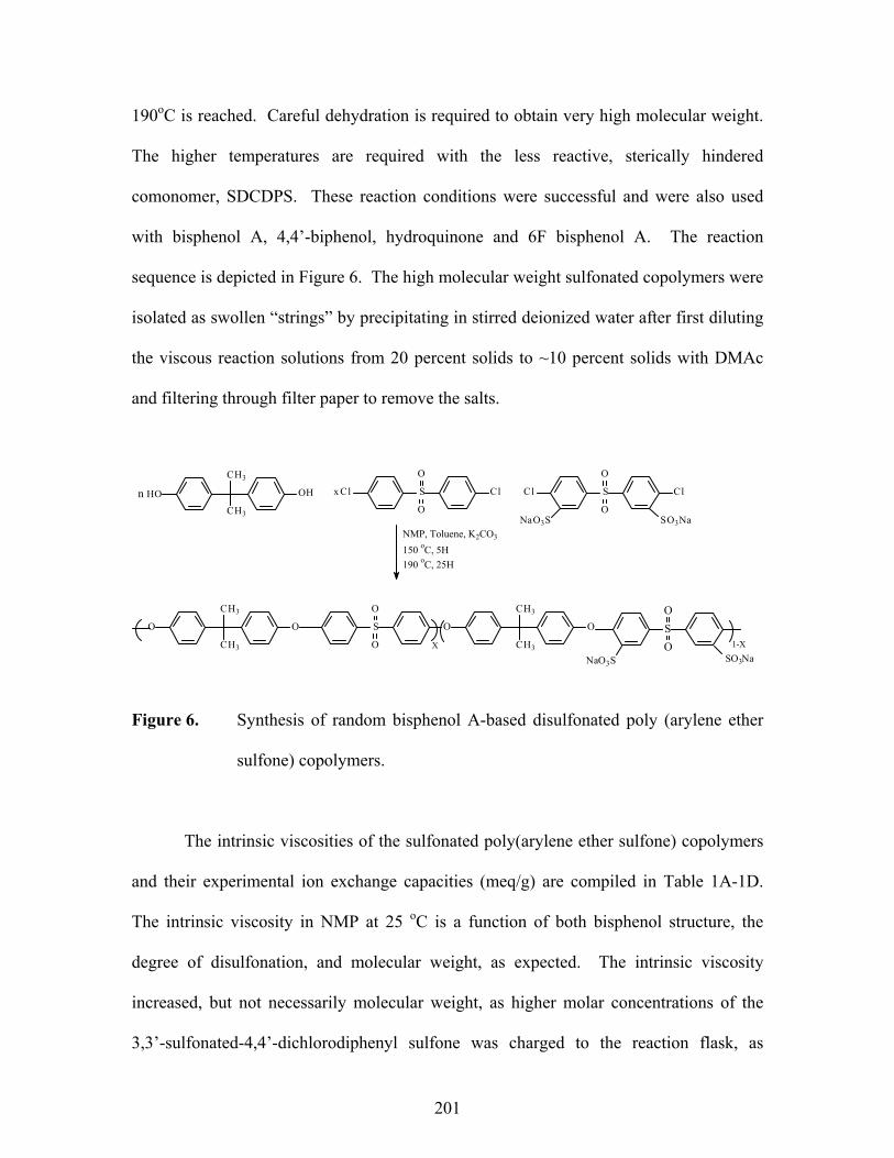
201
190oC is reached. Careful dehydration is required to obtain very high molecular weight.
The higher temperatures are required with the less reactive, sterically hindered
comonomer, SDCDPS. These reaction conditions were successful and were also used
with bisphenol A, 4,4’-biphenol, hydroquinone and 6F bisphenol A. The reaction
sequence is depicted in Figure 6. The high molecular weight sulfonated copolymers were
isolated as swollen “strings” by precipitating in stirred deionized water after first diluting
the viscous reaction solutions from 20 percent solids to ~10 percent solids with DMAc
and filtering through filter paper to remove the salts.
Figure 6. Synthesis of random bisphenol A-based disulfonated poly (arylene ether
sulfone) copolymers.
The intrinsic viscosities of the sulfonated poly(arylene ether sulfone) copolymers
and their experimental ion exchange capacities (meq/g) are compiled in Table 1A-1D.
The intrinsic viscosity in NMP at 25 oC is a function of both bisphenol structure, the
degree of disulfonation, and molecular weight, as expected. The intrinsic viscosity
increased, but not necessarily molecular weight, as higher molar concentrations of the
3,3’-sulfonated-4,4’-dichlorodiphenyl sulfone was charged to the reaction flask, as
CH3
CH3
n HO OH S
O
O
x Cl Cl S
O
O
Cl Cl
NaO3S SO3NaNMP, Toluene, K2CO3
150 oC, 5H190 oC, 25H
CH3
CH3
O O S O
O
O
CH3
CH3
O SO
ONaO3S SO3Na
X 1-X

202
observed for other ionomers28. Redissolving the isolated copolymers in DMAc produced
homogeneous solutions, which were cast onto glass substrates to form coherent films.
Even though apparently high intrinsic viscosities (~ 1.5 dL/g) were determined,
somewhat brittle dry film behavior could be noted when greater than 40 mol% SDCDPS
was used, especially for the 6F bisphenol A copolymer, if the reaction was stopped after
only 20 hours. The lower reactivity of the deactivated 6F bisphenol A phenolate may
have produced lower molecular weight copolymers which caused the films to be less
ductile in the dry state. Difficulties were apparently encountered by earlier workers24 as
evident by lower inherent viscosities, under their reaction condition, when 30 mol%
SDCDPS was used. Simply increasing copolymerization time for these second order
reactions (up to 40 hours) at 190 oC was successful in yielding ductile films, which
correlated with solution intrinsic viscosities values in NMP greater than 2.0 dL/g.
The synthesis of 3,3’-disulfonated-4,4’-difluorodiphenyl sulfone has been
reported from our laboratory earlier, and was employed to investigate related sulfonated
poly(sulfide sulfones) 29. Accordingly, the higher reactivity of SDFDPS was exploited to
produce higher molecular weight sulfonated copolymers, as suggested by the intrinsic
viscosities and film ductility. Bisphenol A, biphenol, hydroquinone, and 6F bisphenol A
were reacted with 4,4’-difluorodiphenyl sulfone (DFDPS) and 3,3’-sulfonated-4,4’-
difluorodiphenyl sulfone (SDFDPS), respectively. The lower (175 oC) polymerization
temperature proved to be significant; some degradation process (possibly only involving
the reaction solvent) occurs at elevated temperatures using DFDPS/SDFDPS system as
observable by a darker reaction mixture, which can afford brittle films. The successful

203
results are also tabulated in the tables (Table 1A – 1D). Creasible films of all the
sulfonated copolymers (up to 60 mol% disulfonated dihalide) were obtained.
FTIR and 1H NMR were powerful tools used to identify and characterize the four
series of sulfonated copolymers. NMR allowed for compositional and structural
determinations for each copolymer. Integration and appropriate analysis of known
reference protons of the copolymer allowed the relative composition of the various
copolymers to be determined. The protons adjacent to the sulfonate group derived from
the disulfonated dihalide monomer in the copolymer were well separated from the other
aromatic protons (~8.25 ppm). The 1H NMR for the copolymer 6F-30 in Figure 7 is a
representative spectrum. The calculation is provided for 6F-3030. The integration
concluded that 27 mol% of 3,3’-disulfonated-4,4’-dichlorodiphenyl sulfone was
incorporated into the polymer. This may be within reasonable experimental error for this
method. Alternatively, proper weighing of the hydroscopic monomer is challenging.
Similar calculations done for all four sulfonated copolymer series are tabulated on Tables
1A-1D.

204
Figure 7. 1HNMR of 6F-30 sulfonated poly(arylene ether sulfone) copolymer, in
DMSO-d6.
Standardized FTIR spectra allowed for qualitative and quantitative determination
of the functional groups of the synthesized copolymers. Figure 8 shows the FTIR series
for 4,4’-biphenol based sulfonated copolymer series as a function of degree of
sulfonation. The IR peak at 1008 cm–1 is characteristic of the Ar-O-Ar linkage, which
was selected for normalizing each of the sulfonated copolymers. Peaks at 1030 cm–1
corresponded to a vibrational stretching for the salt of the sulfonic acid group. The
intensity increased with the amount of the incorporated sulfonated dihalide, which was
observed for all sulfonated copolymer series.
8.5 8.0 7.5 7.0 PPM
O
CF3
CF3
O S
O
O
O
CF3
CF3
OS
O
O
HO3S SO3H
70%
30%
a b c d
e
efghij
k
k
d
i
c
f, g, j
a, b
h, e

205
Figure 8. Influence of the degree of sulfonation on the FT-IR of biphenol-based
sulfonated poly (arylene ether sulfone) copolymers.
Thermo-oxidative behavior of all unsulfonated (control) and sulfonated
copolymers were investigated by thermogravimetry programmed from 30 to 800 oC at a
heating rate of 10 oC/min under in air. All salt-form sulfonated copolymers displayed
very high stabilities comparable to their respective control polymers. The partially
aliphatic bisphenol A based copolymers, in general, displayed the lowest thermo-
oxidative stabilities (5% weight loss of ~490 oC) regardless of sulfonation level. This
may be attributed to the aliphatic C-H bonds of the isopropylidene group. The biphenol
and hydroquinone based copolymers displayed similar thermal behavior with initial 5%
weight losses of ~520 oC. An increase in the degree of disulfonation within the
PBPS-60
PBPS-40
PBPS-30
PBPS-20
PBPS-10
PBPS-00
-0.2
-0.0
0.2
0.4
0.6
0.8
1.0
1.2
1.4
1.6
1.8
950 1000 1000 1500
cm-1
1006cm-1
1098, 1030cm-1

206
copolymers increased the resulting char yields and this trend was typical for all four
copolymer series.
The dried, acid-form copolymer samples were examined under the same drying
and heating conditions. A two-step degradation profile was observed for all copolymers
in their acid-form, Figure 9. The first weight loss is typically assigned to desulfonation
processes while the second weight loss peak is due to main chain polymer degradation7,8.
At copolymer compositions of less than 40 percent the first weight loss observed is over
350 oC. These temperatures are much higher than was anticipated. However, at higher
degrees of sulfonation the initial 5% weight loss was significantly lower, ~230 oC. This
may be due to difficulty in water removal, or that more than one origin of weight loss.
Zaidi et al. observed higher than theoretical desulfonation weight loss while investigating
post- sulfonated PEEK samples31. Moreover, Samms et al. utilized TGA coupled to mass
spectrometry (TGA-MS) to show that only partial polymer desulfonation occurs over the
temperature range of 200 – 300 oC32. Tightly bound water associated with the sulfonic
acid groups33 may be present, even after the applied drying conditions, which may be
related to mobility issues, eg. glass transition temperature.

207
Figure 9. Influence of the copolymer composition on the TGA thermograms of acid-
form 6F-based sulfonated copolymers, in air at 10 oC/min.
To further explore desulfonation temperatures (i.e., thermal oxidative stability of
the pendent sulfonic acid group) a modified heating cell was connected to the FTIR. A
ceramic heating cell allowed for copolymer films to be examined after exposure to a
programmed temperature. Figure 10 displays the FTIR spectra series of 6FSH-30 after
treatment at 140–260 oC in the heating cell for 30 minutes. Monitoring the sulfonic acid
peak at 1030 cm-1 one can see a discernible change in the selected scans. The FTIR
spectra at 180 and 220 oC show very similar profiles. When the film is exposed to 260 oC
for 30 minutes there is an apparent decrease in peak intensity. This decrease can be due
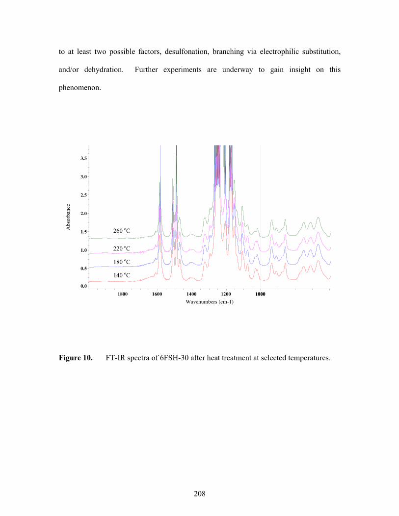
208
to at least two possible factors, desulfonation, branching via electrophilic substitution,
and/or dehydration. Further experiments are underway to gain insight on this
phenomenon.
Figure 10. FT-IR spectra of 6FSH-30 after heat treatment at selected temperatures.
260 oC
220 oC
180 oC
140 oC
0.0
0.5
1.0
1.5
2.0
2.5
3.0
3.5
Abs
orba
nce
1000 1000 1200 1400 1600 1800 Wavenumbers (cm-1)

209
Solution Behavior and Water Uptake
The sulfonated poly(arylene ether sulfone) copolymers were tested for solubility
in several common solvents, include NMP, DMAc, chloroform, and water. The
copolymers were examined at typically 10% solutions (w/v) in each potential solvent.
All control and sulfonated copolymers were soluble in NMP and DMAc and when
agitated with a magnetic stir bar yielded clear, homogeneous solutions. After four weeks
the unsulfonated hydroquinone control polymer (HQ-00) solution became opaque and
eventually crystallized from the DMAc solution. No precipitation/crystallization was
observed at any composition of the hydroquinone-based sulfonated copolymers. The
bisphenol A-based copolymers were soluble in chloroform at compositions of up to 30
mol percent sulfonated dihalide, while higher sulfonated membranes formed apparent
gels.
Poly(arylene ether sulfone)s are, in general, hydrophobic polymers. The
hydrophilic nature of the sulfonated poly(arylene ether sulfone)s have been examined by
water sorption/uptake measurements. All the sulfonated copolymers were swollen by
deionized water at 30 oC but were not soluble. Ueda et al. reported lower water contact
angles as a function of sulfonation compared to the unsulfonated control polymer24. The
water sorption of modified membranes was a function of both the degree of sulfonation
and the molecular structure. Water uptakes, at 30 oC, as a function of the degree of
sulfonation and bisphenol are summarized in Table 3. The formula used for water uptake
was,

210
Water uptake = %100×−
dry
drywet
WWW
where Wwet and Wdry are the weights of the wet and dry membranes, respectively. The
Wdry for each film was the stable (equilibrium) weight of the polymer after drying under
vacuum at 120 oC for at least 24 hours. Wwet was determined after submersion in
deionized water at 30 oC for 48 hours and the excess water removed by blotting with a
paper towel. This was sufficient time to reach equilibrium at this temperature. The
results are tabulated on Table 3.
The water uptake for each copolymer increased with increasing sulfonation, but
the bisphenol also had a marked influence on the water sorption. While bisphenol A and
biphenol displayed similar water sorption, hydroquinone at equivalent mole percents was
higher than comparably sulfonated copolymers. Conversely, 6F bisphenol A systems had
the lowest water sorption. This result was anticipated due to the hydrophobic nature of
hexafluoroisopropylidene connecting units.
One can hypothesize that an optimal degree of sulfonation could exist depending
on the various proposed application. For the bisphenol A, biphenol, and hydroquinone
sulfonated copolymer series a drastic increase in water uptake is observed at different
composition, over an approximately 10 mol% sulfonation increment, depending on the
bisphenol. Thus, a water sorption of 140 weight percent was exhibited by HQ-60, which
was almost twice the water uptake of the HQ-50 copolymer. Water uptakes of more than
70 weight percent were determined for Bis A-60 and BP-60. However, over the
examined range of sulfonation, similar suddenly high water uptakes for 6F bisphenol A-

211
based sulfonated copolymers require higher sulfonated comonomer concentrations.
Using tapping mode-atomic force microscopy (TM-AFM), an extension of our
earlier studies22,26 show there appears to be a morphological phase change within the
sulfonated copolymers, corresponding to the observed abrupt increase in water uptake,
and these points will be further amplified elsewhere27. While the sulfonated poly(arylene
ether sulfone) copolymers with the excessively high water uptake may have applicability
to other technologies, they are probably not useful PEMs. As expected, the mechanical
properties of the highly water swollen copolymers are low compared to the other
moderately hydrophilic sulfonated copolymers.
CONCLUSIONS
An improved method was developed for preparing 3,3’-disulfonated 4,4’-
dichlorodiphenyl sulfone and the analogous 3,3’-disulfonated-4,4’-difluorodiphenyl
sulfone monomers in high yields. A series of novel sulfonated poly (arylene ether
sulfone)s were synthesized via direct copolymerization of the disulfonated dihalide
sulfone monomers with 4,4’-dichlorodiphenyl sulfone and any of four different
bisphenols. This method resulted in the random incorporation of the sulfonated monomer
throughout the copolymers, probably through the well-known ether-ether interchange
process. Varying the stoichiometric ratio of the disulfonated activated aryl dihalide
comonomer to the unmodified dihalide comonomer easily controlled the degree of
disulfonation in the copolymers. Moreover, the direct copolymerization strategy
positioned the sulfonic acid groups on the more stable, and more acidic deactivated

212
sulfone unit as opposed to polymer (post) sulfonation of the electron rich bisphenol
moieties.
The bisphenol structure and degree of disulfonation influenced the properties of
the sulfonated copolymers, including solubility, ion exchange capacity, and water uptake.
All sulfonated copolymers were soluble in polar, aprotic solvents at room temperature.
The ion exchange capacities of the sulfonated copolymers were easily controlled by
changing the molar ratio of the DCDPS to sulfonated DCDPS. Water uptake increased
linearly with increasing degrees of sulfonation up to 50 mol% of the disulfonated repeat
unit. However, at compositions higher than 50 mol% of the disulfonated unit, dramatic
increases in water uptake and related membrane swelling were observed. The
copolymers containing hydroquinone exhibited the highest water uptake, while the 6F
bisphenol A sorbed the lowest values. The proton conductivity and other critical PEM
features for fuel cells will be reported in Part II in this journal.
ACKNOWLEDGEMENTS
The authors are indebted to Mr. Tom E. Glass for his technical assistance with the
NMR analysis, and to Professor Thomas Zawodzinski (Case Western Reserve
University) for helpful discussions. The authors would also like to thank the National
Science Foundation Partnership for Innovation (HER-0090556) and Department of
Energy (DE-FC36-01G01086) for support of this research effort.

213
REFERENCE 1. Robeson, L. M.; Farnham, A. G.; and McGrath, J. E., Dynamic Mechanical
Characteristics of Polysulfone and Other Polyarylethers; in Molecular Basis for
Transitions and Relaxations, D. J. Meier, Ed., Midland Macromolecular Institute
Monographs, 1978, Vol. 4, p. 405; (b) Dumais, J. J.; Cholli, A. L.; Jelinski, L. W.;
Hedrick, J. L.; and McGrath, J. E., Molecular Basis of the b-Transition in
Poly(arylene ether sulfone)s, Macromolecules 1986, 19, 1884.
2. Cotter, R. J., Engineering Plastics: Handbook of Polyarylethers; Gordon and
Breach Publishers: Basel, Switzerland, 1995; (b) S. Wang and J. E. McGrath, “
Polyarylene Ethers”: A Review, in M. Rogers and T.E. Long, eds., Step
Polymerization, Wiley, 2002.
3. Johnson, R. N.; Farnham, A. G.; Clendinning, R. A.; Hale, W. F.; and Merriam,
C. N., J. Polym. Sci., Polym. Chem. Ed. 1967, 5, 2375, and (b) Johnson, R.N.
Encyclopedia of Polymer Science and Technology; N.M. Bikales, Ed., Wiley,
New York (1969).
4. Clagett, D.C., in Encyclopedia of Polymer Science and Engineering, Vol. 6;
Mark, H.F.; Bikales, N.M.; Overberger, C.G.; Menges, G., Eds., John Wiley &
Sons: New York, 1986, p. 94.
5. Noshay, A.; Robeson, L. M., J. Appl. Polym. Sci. 1976, 20, 1885.
6. Johnson, B. C.; Yilgor, I.; Tran, C.; Iqbal, M.; Wightman, J. P.; Lloyd, D. R.;
McGrath, J. E., J. Polym. Sci. 1984, 22, 721.
7. Quentin, J. P., Sulfonated Polyarylether Sulfones, U.S. 3,709,841, Rhone-
Poulenc, January 9, 1973.
8. Nolte, R.; Ledjeff, K.; Bauer, M.; Mulhaupt, R., J. Membr. Sci., 83 (1993) 211.

214
9. Chao, H. S.; Kelsey, D. R., Process for preparing sulfonated poly(arylether)
resins, U.S. 4,625,000 to Union Carbide, November 25, 1986.
10. Lufrano, F.; Gatto, I.; Staiti, P.; Antonucci, V.; Passalacqua, E., Solid State Ionics
2001, 145, 47.
11. Lee, J.; Marvel, C. S., J. Polym Sci.: Polym. Chem.Ed. 1984, 22, 295.
12. Steck, A.; Stone, C.,, in Proceedings of the Second International Symposium on
New Materials for Fuel Cells and Modern Battery Systems, O. Savadogo and P.
R. Roberge, Eds., Montreal, Canada, July 6-10, 1997.
13. Baradie, J.B.; Poinsignon, C.; Sanchez, J. Y.; Piffard, J.; Vitter, G.; Bastaoui, N.;
Forcallo, D.; Denoyelle, A.; Delabouglise, D.; Vaujany, M., J. Power Sources
1998, 74, 8.
14. Bailly, C.; Williams, D. J.; Karasz, F. E.; MacKnight, W. J., Polymer 1987, 28,
1009.
15. Bishop, M. T.; Karasz, R. D.; Russo, P. S.; Langley, K. H., Macromol. 1985, 18,
86.
16. Kerres, J.; Cui, W.; Richie, S., J.Polym. Sci. 1996, 34, 2421, and (b) Kerres, J.;
Zhang, W.; Cui, W., J. Polym. Sci. Part A: Polym. Chem. 1998, 36, 1441.
17. Wang, F.; Chen, T.; Xu, J., Macromol. Chem. Phys. 1998, 199, 1421; (b) Wang,
F.; Li, J.; Chen, T.; Xu, J., Polymer, 40, (1999), 795; (c) Wang, F.; Qi, Y. H.;
Chen, T. L.; Xing, Y.; Lin, Y. H.; Xu, J.P., Acta Crystallographica Section C-
Crystal Structure Comm. 1999, 55, 871.
18. Mercier, R. et al., 5th European Technical Symposium on Polyimides and High
Performance Functional Polymers Proceedings, May 3-5, 1999, Montpellier,
215
France, and (b) Genies, C.; Mercier, R.; Sillion, B.; Cornet, N.; Gebel, G.; Pineri,
M., Polymer 2001, 42, 359.
19. Gunduz, N.; McGrath, J. E., ACS Polymer Preprints 2000, 41(2), 1565; (b)
McGrath, J. E. et. al., ACS Polymer Preprints 2002, 43 (1).
20. Wang, F.; Mecham, J.; Harrison, W.; McGrath, J. E., ACS Polymer Preprints
2000, 40(2), 1401.
21. Shobha, H. K.; Smalley, G. R.; Sankarapandian, M.; McGrath, J. E., ACS
Polymer Preprints 2000, 40(1), 180.
22. Wang, F.; Hickner, M.; Ji, Q.; Harrison, W.; Mecham, J.; Zawodzinski, T.;
McGrath, J. E., Macromol. Symp. 2001, 175(1), 387; (b) ibid, Macromol. Symp.
2003, in press.
23. L. M. Robeson, and M. Matzner, U.S. Patent 4,380,598, Flame Retardant
Polyarylate Compositions, April 19, 1983.
24. Ueda, M.; Toyota, H.; Ochi, T.; Sugiyama, J.; Yonetake, K.; Masuko, T.;
Teramoto, T., J. Polym. Sci.: Polym. Chem. Ed. 1993, 31, 85.
25. Appleby, A. J.; Foulkes, F. R., Fuel Cell Handbook; Van Nostrand Eeinhold, NY,
1989, and (b) Zalbowitz, M.; Thomas, S., Fuel Cells: Green Power; Department
of Energy, 1999 LA-UR-99-3231.
26. Wang, F.; Hickner, M.; Kim, Y. S.; Zawodzinski, T. A.; McGrath, J. E., J.
Membr. Sci. 2002, 197, 231.
27. Kim, Y. S.; Wang, F.; Hickner, M.; McCartney, S.; Hong, Y. T.; Harrison, W.;
Zawodzinski, T. A.; McGrath, J. E., J. Polym. Sci: Physics. 2002 in press.

216
28. Wilkes, G. L.; Tant, M. R.; Mauritz, K. A., Eds. Ionomers: Synthesis, Structure,
Properties and Applications; Blackie Academic and Professional: New York,
1997.
29. Wang, F.; Mecham, J., Harrison, W., McGrath, J.E., ACS Polymer Preprints
2000, 40(1), 180; (b) Wiles, K.E.; Bhanu, V. A.; Wang, F.; McGrath, J. E., ACS
Polymer Preprints 2002, 42(2)..
30. Determination of Degree of Sulfonation in 6F-30 copolymer via 1H NMR
Using the integration for the 2- k protons (Ik) and
the integration for the 8-(a + b) protons (I(a+b)),
if Ik = 3.6 and I(a+b) = 52.8, respectively,
then [ Ik / 2 protons] ÷ [(I(a+b)) / 8 protons] = Percent Sulfonated Repeat Unit
So, [ 3.6 / 2 ] ÷ [ 52.8 / 8 ] = 1.8 ÷ 6.6 =
0.273 x 100% = 27.3% Sulfonated Repeat Units
31. Zaidi, S. M. J.; Mikhailenko, S. D.; Robertson, G. P.; Guiver, M. D.; Kaliaguine,
S., J. Membr. Sci. 2000, 173, 17.
32. Samms, S. R.; Wasmus, S.; Savinell, R. F., J. Electrochem Soc 1996, 143, 1498.
33. Hodge, R. M.; Bastow, T. J.; Edward, G. H.; Simon, G. P.; Hill, A. J., Macromol.
1996, 29, 8137.
34. Rose, J. B., J. Chem. Soc. 1973.

217
Table 1A. Influence of Degree of Disulfonation on Several Features of Bisphenol A
based Copolymers
Bisphenol XX,
mol% SDCDPS
Degree of Sulfonation by 1H NMR
[η]NMP IEC#, meq/g Water Uptake, weight %
Bis A 0 - 0.70 0 3 Bis A 10 12 0.78 0.41 7 Bis A 20 18 0.82 0.79 13 Bis A 30 31 1.20 1.12 27 Bis A 40 37 1.86 1.58 37 Bis A 50 48 2.48
2.75* 1.78 48
Bis A 60 56 2.80 3.08*
2.13 68
* Copolymerization using DFDPS/SDFDPS system. # Determined from non-aqueous potentiometric titration.
25oC

218
Table 1B. Influence of Degree of Disulfonation on Several Features of Biphenol
based Copolymers
Bisphenol XX,
mol% SDCDPS
Degree of Sulfonation by 1H NMR
[η]NMP IEC, meq/g Water Uptake, weight %
Biphenol 0 - 0.65 0 2 Biphenol 10 8 0.70 0.41 5 Biphenol 20 23 0.93 0.89 10 Biphenol 30 31 1.51 1.31 18 Biphenol 40 40 1.82 1.51 28 Biphenol 50 49 2.09
2.52* 1.98 38
Biphenol 60 58 2.69 2.94*
2.22 55
* Copolymerization using DFDPS/SDFDPS system. # Determined from non-aqueous potentiometric titration
25oC

219
Table 1C. Influence of Degree of Disulfonation on Several Features of 6F Bisphenol
A based Copolymers
Bisphenol XX,
mol% SDCDPS
Degree of Sulfonation by 1H NMR
[η]NMP IEC#, meq/g Water Uptake, weight %
6F 0 - 0.59 0 2 6F 10 9 0.69 0.32 5 6F 20 19 0.86 0.59 9 6F 30 27 1.49 0.87 13 6F 40 41 1.70 1.16 25 6F 50 52 2.01
2.42* 1.50 34
6F 60 58 2.07 2.53*
1.77 42
* Copolymerization using DFDPS/SDFDPS system. # Determined from non-aqueous potentiometric titration.
25oC

220
Table 1D. Influence of Degree of Disulfonation on Several Features of
Hydroquinone based Copolymers
Bisphenol XX,
mol% SDCDPS
Calc’d. Degree of
Sulfonation by 1H NMR
[η]NMP IEC#, meq/g Water Uptake, weight %
HQ 0 - 0.89 0 2 HQ 10 13 0.86 0.60 7 HQ 20 18 1.20 1.00 23 HQ 30 32 1.82 1.58 31 HQ 40 38 2.29 1.94 50 HQ 50 46 2.37
2.65* 2.48 68
HQ 60 55 2.41 2.88*
2.77 >140
* Copolymerization using DFDPS/SDFDPS system. # Determined from non-aqueous potentiometric titration
25oC

221
CHAPTER 5
SUMMARY AND CONCLUSIONS
This research involved the synthesis and characterization of poly (arylene ether
sulfone) copolymers as candidates for proton exchange membranes in fuel cells. The
principal objective of this research was to systematically synthesize four series of
sulfonated poly (arylene ether sulfone) copolymers containing controlled amounts of
sulfonic acid groups via the direct copolymerization of sulfonated comonomers. As
important to fuel cell operation conditions, the four novel sulfonated copolymers were
evaluated for their film- forming characteristics, water uptake, morphology, ion-exchange
capacity, and proton conductivity. The thermal stabilities of the copolymers were also
evaluated.
Five sulfonated monomers were synthesized by electrophilic aromatic substitution
of commercially available compounds 4,4’-bisphenol A, 4,4’-biphenol, 6F bisphenol A,
4,4’-dichlorodiphenyl sulfone, and 4,4’-difluorodiphenyl sulfone in fuming sulfuric acid
and isolated as their respective sodium salts. Due to insolubility of the three sulfonated
bisphenols they could not be copolymerized under the conditions employed in this work,
but they are recommended for use in future research. However, 3,3’-disulfonated 4,4’-
dichlorodiphenyl sulfone (SDCDPS) and 3,3’-disulfonated 4,4’-difluorodiphenyl sulfone
(SDFDPS) were synthesized with high purity in very good yields.
Four bisphenols, bisphenol A, biphenol, 6F bisphenol A, and hydroquinone, were
utilized in the direct copolymerization with either dichlorodiphenyl sulfone and
sulfonated dichlorodiphenyl sulfone or difluorodiphenyl sulfone and sulfonated
difluorodiphenyl sulfone to yield high molecular weight, film-forming polymers. The
copolymerizations produced random sulfonated poly (arylene ether sulfone) copolymers
with up to 60 mol% sulfonated dihalide comonomer. Essentially quantitative
incorporation of the 3,3-sulfonated-4,4’-dichlorodiphenyl sulfone or 3,3’-sulfonated-4,4’-
difluorodiphenyl sulfone into the copolymers was achieved based on potentiometric
titration, 1H NMR and FTIR spectroscopic methods, and the copolymers compositions

222
were easily controlled by varying the comonomers’ stoichiometric feed ratios. The
influence of the bisphenol structure, as well as the degree of sulfonation, on the properties
of each sulfonated poly (arylene ether sulfone) copolymers was of particular interest.
All four copolymer series demonstrated high thermo- oxidative stability in their
acid-form with no significant weight loss until ~300 oC in TGA at 10 oC /min. The salt
form of each sulfonated copolymer was also evaluated and showed comparable stabilities
to its respective control polymer. The sulfonated copolymers demonstrated a two-step
degradation. The first weight loss between 300 - 400 oC was attributed to desulfonation
and the loss of absorbed or bound water. The second weight loss, typically at 450 oC,
was due to the decomposition of the polymer backbone. The polymer backbone thermo-
oxidative degradation was dependent upon the bisphenol structure, with bisphenol A-
based copolymers being the least stable. The acid-form 5% weight loss temperatures for
all four copolymer series decreased with increasing sulfonation, but these temperatures
are considerably above the proposed operation temperature (120 -150oC) of proton
exchange membrane fuel cells.
Water uptake and proton conductivities were determined for each sulfonated poly
(arylene ether sulfone) copolymer. The water uptake increased as a function of
disulfonation. Also, the bisphenol structure influenced the amount of water absorbed by
the copolymers. Hydroquinone-based sulfonated copolymers showed the highest water
uptake at comparable degrees of sulfonation while 6F bisphenol A-based copolymers
showed the lowest. It was shown that the acidification method as well as the drying
conditions also played prominent roles in water uptake. The very high levels of water
uptake of many of the highly sulfonated copolymers may limit their applicability in
PEMFCs due to excessive swelling.
The proton conductivities of each sulfonated copolymer also increased with
increasing degrees of sulfonation. This agrees well with expectations due to the related
increase in the ion exchange capacity, i.e., the increasing number of pendant sulfonic acid
groups. The conductivity measurements for optimized copolymers established values
that matched or surpassed those of commercial control Nafion under similar test
conditions (0.1 S/cm at 30 oC). The water content and closely related acidification
method influenced the measured conductivities. Importantly, under similar conditions it

223
was determined that across the four copolymer series the proton conductivities were the
same at similar ion exchange capacities. This conclusion should be expected but has not
been highlighted or reported by others. This is probably due to difficulties in the control
of polymer post-sulfonation reactions and the lack of a previous systematic study.

224
CHAPTER 6
SUGGESTED FUTURE WORK
Results outlined in previous chapters demonstrated the vast opportunities of
synthesizing novel polymeric materials and the exciting ability to influence several
important properties. There is still a great deal of information that needs to be
ascertained in order to completely understand the structure-property relationships of the
copolymers and their effects on the membrane properties. The incorporation of bis (4-
hydroxyphenyl) phenyl phosphine oxide (BOHPPO) or other monomers containing polar
groups may provide polymers with interesting properties. These polar groups may be
able to interact with the pendent sulfonic acid groups. Xiao et al.336 recently reported
lower water uptake by incorporating carbonyl groups, which the authors demonstrated via
FTIR studies to be due to the presence of hydrogen bonding. These results are consistent
with unpublished data on sulfonated poly (arylene ether) copolymers that contain polar
nitrile groups337.
It is also recommended that work continue on a procedure to copolymerize the
sulfonated bisphenols described in this research--in particular disulfonated biphenol and
disulfonated 6F bisphenol A. Such a study may be in order to provide a comprehensive
comparison on the impact of the location (activated vs. deactivated ring) of the pendent
sulfonic acid on stability, acidity, etc. The isolation of a different salt, perhaps the
potassium or lithium salt, may lead to improved solubility. The use of co-solvents may
be necessary to obtain the desired solution. Due to the high water solubility of the
sulfonated bisphenol salts, the use of a small amount of water as part of the co-solvent
system may be possible. The water will be removed azeotropically during the reaction.
The investigation on the synthesis of sulfonated block copolymers for direct
comparison to the random copolymers synthesized in this research may provide
interesting microstructures and properties. Poly (arylene ether ketone)-block- sulfonated
336 Xiao, G.; Sun, G.; Yan, D.; Zhu, P.; Tao, P., Polymer 2002, 43, 5335. 337 Mike Sumner, Ph.D Candidate, VPI & SU, Personal Conversation, July 2002.

225
poly (arylene ether sulfone) copolymers are only one possibility. The unsulfonated
polyketone block will be hydrophobic and may modify or restrict the water sorption of
the sulfonated block domains. The success of this reaction will depend on the careful
control of the molecular weight of the blocks, the minimization of ether-ether interchange
reactions, and the separation of the two blocks. The selection of the poly (ether ketone)
block may be important –especially considering the possibility of this segment being
semi-crystalline.
As mentioned in Chapter 1, considerable work has been initiated using additives
such as various heteropolyacids (HPA). Some work has already been done by my
colleague Dr. Kim in our group using the biphenol-based poly (arylene ether sulfone)
copolymers and has shown improved conductivity and modification in water uptake with
the incorporation of different weight percents of tungsten or zirconium- based HPAs.
More extensive work should be done using the various copolymer systems using the data
and knowledge gained in this research.

226
APPENDIX
SYNTHESIS OF SULFONATED POLY (ARYLENE ETHER SULFONES) VIA
CHLOROSULFONIC ACID
As detailed in Chapter 1 the sulfonation of polymers has been investigated for
over four decades. While many sulfonating agents have been employed chlorosulfonic
acid was selected in this research due to its simplicity and adaptability. For instance,
sulfuric acid has been criticized for its heterogeneous nature in generating sulfonated
polymers while sulfur trioxide and sulfur trioxide complexes require special handling and
/ or preparation. The sulfonation of pre-dissolved polymers via chlorosulfonic acid
allows for a statistically equivalent opportunity for each repeat unit to undergo
electrophilic substitution. Furthermore, no additional preparation is required for
chlorosulfonic acid use.
In this study sulfonated poly (arylene ether sulfones) were successfully produced
using chlorosulfonic acid or its trimethyl silylated derivative. The degree of sulfonation
was controlled, to some extent, by varying the molar equivalents of polymer to
chlorosulfonic acid. The reaction scheme is given below.
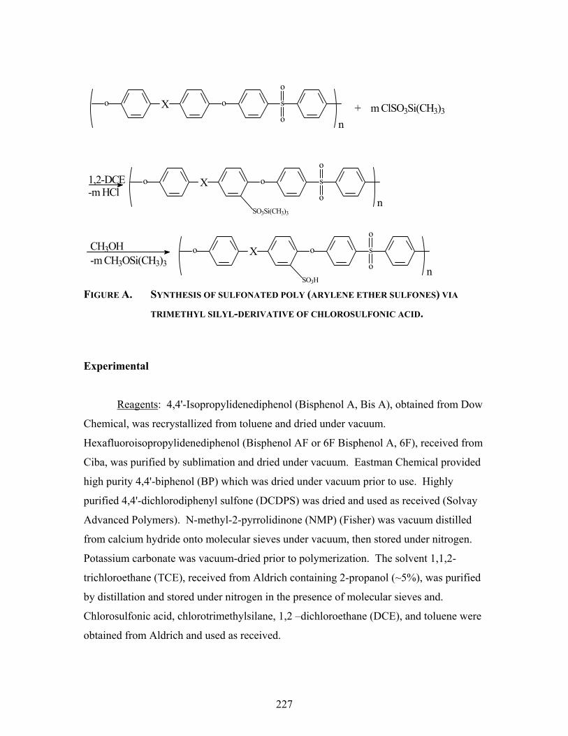
227
FIGURE A. SYNTHESIS OF SULFONATED POLY (ARYLENE ETHER SULFONES) VIA
TRIMETHYL SILYL-DERIVATIVE OF CHLOROSULFONIC ACID.
Experimental
Reagents: 4,4'-Isopropylidenediphenol (Bisphenol A, Bis A), obtained from Dow
Chemical, was recrystallized from toluene and dried under vacuum.
Hexafluoroisopropylidenediphenol (Bisphenol AF or 6F Bisphenol A, 6F), received from
Ciba, was purified by sublimation and dried under vacuum. Eastman Chemical provided
high purity 4,4'-biphenol (BP) which was dried under vacuum prior to use. Highly
purified 4,4'-dichlorodiphenyl sulfone (DCDPS) was dried and used as received (Solvay
Advanced Polymers). N-methyl-2-pyrrolidinone (NMP) (Fisher) was vacuum distilled
from calcium hydride onto molecular sieves under vacuum, then stored under nitrogen.
Potassium carbonate was vacuum-dried prior to polymerization. The solvent 1,1,2-
trichloroethane (TCE), received from Aldrich containing 2-propanol (~5%), was purified
by distillation and stored under nitrogen in the presence of molecular sieves and.
Chlorosulfonic acid, chlorotrimethylsilane, 1,2 –dichloroethane (DCE), and toluene were
obtained from Aldrich and used as received.
X o s
o
o
o + m ClSO3Si(CH3)3
n
1,2-DCE-m HCl
n
X o s
o
o
o
SO3Si(CH3)3
CH3OH-m CH3OSi(CH3)3
SO3H
X o s
o
o
o
n

228
Synthesis of Poly(arylene ether sulfone) via Nucleophilic Step-Growth
A typical polymerization for all poly (arylene ether sulfones) will be exemplified
by the synthesis of 4,4’-bisphenol A and 4,4’-dichlorodiphenyl sulfone. Bisphenol A
(3.98 g, 17.4 mmol) and DCDPS (5.00g, 17.4 mmol) were added to a 100mL, 3-neck
flask equipped with an overhead mechanical stirrer, nitrogen inlet and a Dean Stark trap.
Potassium carbonate (2.65g, 19.1 mmol) and NMP (50 mL) were introduced to afford a
20% (w/v) solids concentration. Toluene (25 mL) (usually NMP/Toluene = 2/1, v/v) was
used as an azeotroping agent. The reaction mixture was refluxed at 150 ºC for 4 hours to
dehydrate the system. The temperature was raised to 175 ºC by removal of the toluene.
The reaction was allowed to proceed for approximately 24 hours, during which the
solution became very viscous. The solution was cooled to room temperature and diluted
with 40 mL DMAc to allow easier filtering. After filtering through filter paper to remove
most of the salts, the polymer was isolated by coagulation in a methanol and water
mixture (8/1, v/v) in a Waring blender. The polymers were then dried in a vacuum oven
for at least 24 hours at 150 ºC.
Homogeneous Sulfonation of Poly(arylene ether sulfones) via Timethylsilyl
Chlorosulfonate
Three different poly(arylene ether sulfones) were sulfonated using chlorosulfonic
acid in an inert halogenated solvent. A sample sulfonation will be given using high
molecular weight 6F bisphenol A based poly(arylene ether sulfone) as follows: To a
flame-dried, 100-mL 3-necked round bottom flask fitted with a condenser, an overhead
mechanical stirrer, and a modified addition funnel with a nitrogen inlet 5.5 g (9.9mmol)
of dried polymer was dissolved in 60 mL 1,2-dichloroethane. Next, 11 mmol
chlorotrimethylsilane (~10% molar excess) was added to the solution, followed drop-
wise by 9.9 mmol chlorosulfonic acid diluted in 10 mL dichloroethane over 30 minutes.
The reaction solution was stirred vigorously overnight. The final polymer mixture was
precipitated into stirred cold methanol or isopropanol. The sulfonated polymers were
vacuum dried at 100 oC overnight. The other polymers were sulfonated and isolated via
similar procedures. Biphenol based poly(arylene ether sulfone) was alternatively

229
dissolved in 1,1,2-trichloroethane due to low solubility in dichloroethane.. Polymers that
were alcohol soluble were isolated via roto-evaporation of the low boiling solvents. All
experiments were done in duplicate or triplicate.
Characterization
Intrinsic viscosities were measured in NMP at 25 oC using an Ubbelohde
viscometer. Gel Permeation Chromatography (GPC) measurements were performed to
characterize the molecular weights and molecular weight distributions of the polymers.
The elution solvent for GPC characterization was NMP that contained ~0.02M
phosphorus pentoxide at 60 oC. A Waters 150C instrument, having both a differential
refractive index detector and a Viscotek differential viscometer in parallel, permitted
absolute molecular weight determinations using universal calibration techniques.
FTIR measurements were obtained using a Nicolet Impact 400 instrument. The
FTIR measurements were conducted using thin films of the control, unsulfonated
polymers and the sulfonated polymers. Proton (1H) NMR spectra of all polymers were
obtained in deuterated DMSO (d6-DMSO) at typical concentrations of 7-10% polymer
solution (w/v). Galbrieth Analytical (Tennessee) performed elemental analyses.
Glass transition temperatures (Tg) of the control and modified polymers were
measured with a Perkin-Elmer DSC-7 differential scanning calorimeter at a heating rate
of 10 oC/min. All the reported results were obtained during the second heat and are the
midpoint temperature of the specific heat transition. Thermogravimetric analysis (TGA)
was obtained on a Perkin-Elmer TGA-7 instrument. Samples of 5-10 mg were heated at
10 oC/min from 25 to 800 oC in an air atmosphere.
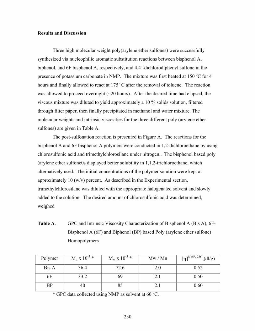
230
Results and Discussion
Three high molecular weight poly(arylene ether sulfones) were successfully
synthesized via nucleophilic aromatic substitution reactions between bisphenol A,
biphenol, and 6F bisphenol A, respectively, and 4,4’-dichlorodiphenyl sulfone in the
presence of potassium carbonate in NMP. The mixture was first heated at 150 oC for 4
hours and finally allowed to react at 175 oC after the removal of toluene. The reaction
was allowed to proceed overnight (~20 hours). After the desired time had elapsed, the
viscous mixture was diluted to yield approximately a 10 % solids solution, filtered
through filter paper, then finally precipitated in methanol and water mixture. The
molecular weights and intrinsic viscosities for the three different poly (arylene ether
sulfones) are given in Table A.
The post-sulfonation reaction is presented in Figure A. The reactions for the
bisphenol A and 6F bisphenol A polymers were conducted in 1,2-dichloroethane by using
chlorosulfonic acid and trimethylchlorosilane under nitrogen.. The bisphenol based poly
(arylene ether sulfone0s displayed better solubility in 1,1,2-trichloroethane, which
alternatively used. The initial concentrations of the polymer solution were kept at
approximately 10 (w/v) percent. As described in the Experimental section,
trimethylchlorosilane was diluted with the appropriate halogenated solvent and slowly
added to the solution. The desired amount of chlorosulfonic acid was determined,
weighed
Table A. GPC and Intrinsic Viscosity Characterization of Bisphenol A (Bis A), 6F-
Bisphenol A (6F) and Biphenol (BP) based Poly (arylene ether sulfone)
Homopolymers
Polymer Mn x 10-3 * Mw x 10-3 * Mw / Mn [η]NMP, 25C,(dl/g)
Bis A 36.4 72.6 2.0 0.52
6F 33.2 69 2.1 0.50
BP 40 85 2.1 0.60
* GPC data collected using NMP as solvent at 60 oC.

231
into a dry vial, and dissolved in ~10 mL solvent. The trimethylchlorosilane was always
used in excess relative to the chlorosulfonic acid.
Three series of sulfonated poly(arylene ether sulfones) with different degrees of
sulfonation were synthesized. In this research chlorotrimethylsilane was employed as a
protecting agent. Trimethylsilyl chlorosulfonate was generated in situ338, as shown in
Figure B. Trimethylsilyl chlorosulfonate is the adduct of chlorotrimethylsilane and
chlorosulfonic acid. It’s purpose is to minimize side reactions with the polymer. The
desired sulfonic acid will be regenerated during the modified sulfonated polymers’
precipitation / isolation steps in alcohol.
FIGURE B. IN SITU GENERATION OF TRIMETHYLSILYL CHLOROSULFONATE.
Several researchers have investigated the use of chlorosulfonic acid as a
sulfonating agent for several aromatic polymers339,340,341,342. As discussed earlier,
undesirable side reactions, including branching and chain-scission, have been observed
during various post-sulfonation reactions of polymers. Polymer chain branching is
possible via protonation of the –OH of a sulfonic acid group followed by the loss of water
generating an active sulfonyl (-SO2+) which can undergo electrophilic substitution on an
338 Nolte, R.; Ledjeff, K.; Bauer, M.; Mulhaupt, R., J. Membr. Sci. 1993, 83, 211. 339 Hamciuc, C.; Bruma, M.; Klapper, M., J. Macromol. Sci.: Pure Appl. Chem. 2001, A 38 (7), 659. 340 Lee, J.; Marvel, C.S., J. Polym. Sci.: Polym. Chem. Ed. 1984, 22, 295. 341 Litter, M.I.; Marvell, C.S., J. Polym. Sci.: Polym. Chem. Ed. 1985, 23, 2205. 342 Genova-Dimitrova, P.; Baradie, B.; Foscallo, D.; Poinsignon, C.; Sanchez, J.Y., J. Membr. Sci. 2001, 185, 59.
Cl S OH
O
O
Cl Si
CH3
CH3
CH3
+ Cl S O
O
O
Si
CH3
CH3
CH3
-HCl

232
adjacent aryl ring. Chao and Kelsey343 recognized that a silyl ester will not have the
acidic proton to catalyze this side reaction. Chain scission most likely occurs at the
isopropylidene group in bisphenol A based polymers, but in the absence of the pendant
acidic group the proposed mechanism is doubtful.
Viscometric measurements were conducted to detect possible chain scission
during the electrophilic substitution. As shown in Table B, the intrinsic viscosities of
each sulfonated polymer series increased with increasing degree of sulfonation. Each
sulfonation reaction (i.e., at a given mol percent chlorosulfonic acid) was done at least
twice; however, the data in Table B is for one experiment. Sulfonated polymers with
comparable degrees of sulfonation had similar intrinsic viscosities, and the average
values are presented in the Tables C1-3. No obvious signs of chain scission or high
extents of branching were observed using this protected sulfonation agent, consistent with
increasing intrinsic viscosity with increasing degrees of sulfonation. This is further
evident by the readily soluble products. The increase in intrinsic viscosity is attributed to
the increase in hydrodynamic size of the sulfonated polymer chain relative to the
unmodified polymer chain. The increase in intrinsic viscosity is consistent with the
trends observed in other polyelectrolytes, including the poly (arylene ether sulfone)
copolymers described in the thesis.
Table B. Averaged intrinsic viscosity data of poly (arylene ether sulfones) and
sulfonated poly (arylene ether sulfones) via chlorotrimethylsilane and
chlorosulfonic acid with different degrees of sulfonation
Actual Degree of Sulfonation Bisphenol type 0 <15% ~25 ~35 ~60
Bis A 0.52 0.59 0.76 0.81 0.93
BP 0.60 0.63 0.70 0.77 0.91
6F 0.50 0.55 0.62 0.70 0.88
343 Chao, H. S., and Kelsey, D. R., US Patent 4,625,000, 1986.

233
FIGURE C1. Infrared spectra of bisphenol A based poly (arylene ether sulfones) with
various degrees of sulfonation.
DS
65
37
0 -1.0
-0.5
0.0
0.5
1.0
1.5
2.0
2.5
3.0
3.5
950 1000 1000 1500 2000 3000 4000 Wavenumbers (cm-1)
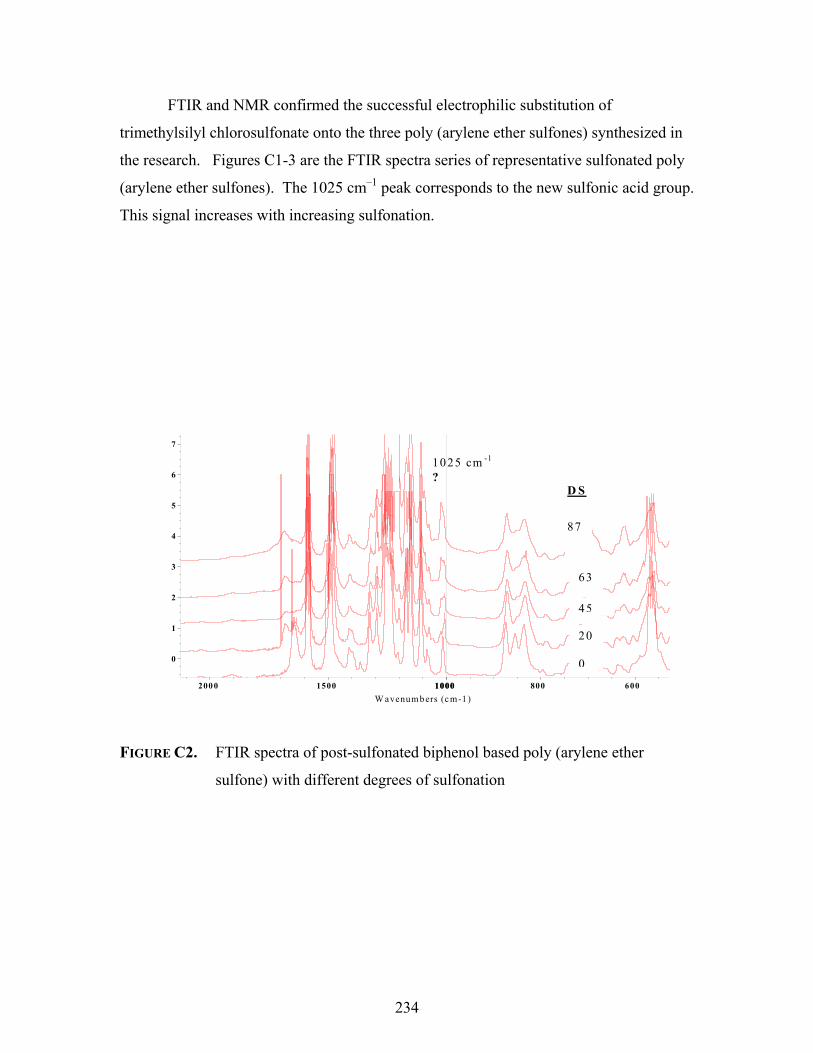
234
FTIR and NMR confirmed the successful electrophilic substitution of
trimethylsilyl chlorosulfonate onto the three poly (arylene ether sulfones) synthesized in
the research. Figures C1-3 are the FTIR spectra series of representative sulfonated poly
(arylene ether sulfones). The 1025 cm–1 peak corresponds to the new sulfonic acid group.
This signal increases with increasing sulfonation.
PRad
WS
PRad
07PR
ad05
0
1
2
3
4
5
6
7
600 800 1000 1000 1500 2000 W avenum bers (c m-1 )
1025 cm -1
? D S
87
63
45
20 0
FIGURE C2. FTIR spectra of post-sulfonated biphenol based poly (arylene ether
sulfone) with different degrees of sulfonation
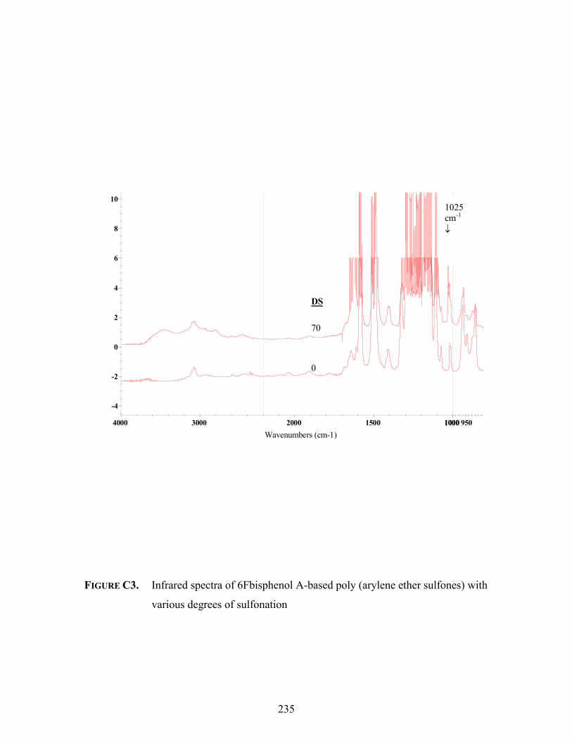
235
FIGURE C3. Infrared spectra of 6Fbisphenol A-based poly (arylene ether sulfones) with
various degrees of sulfonation
Sulfo
natio
n
-4
-2
0
2
4
6
8
10
950 1000 1000 1500 2000 3000 4000 Wavenumbers (cm-1)
1025cm-1
↓
0
70
DS

236
The infrared spectra of all three poly (arylene ether sulfone) polymers and of the
various sulfonated derivatives were normalized using the characteristic absorption band
at ~1010 cm-1. This band is due to the stretching of the carbon-oxygen-carbon linkages
present in all the polymers and is expected to be unaffected during the electrophilic
substitution reaction. Few changes in the spectra are observed at low degrees of
sulfonation; a shoulder or slight broadening of the ether linkage may be the only
noticeable difference. However, as the amount of chlorosulfonic acid is increased in the
reaction, causing a corresponding increase in the degree of sulfonation, the distinct
appearance of an absorption at ~1025 cm-1 was observed. The intensities of the bands
characteristic of the sulfonic acid groups increased with increasing levels of sulfonation,
as expected.
The broad absorption band appearing at ~3400 – 3500 cm-1 may be due to the O-
H vibration from the sulfonic acid group and/or the absorbed water. The polymer films
were all dried prior to taking the spectra under vacuum at 80 oC for at least 12 hours. For
the hydrophilic or water-soluble sulfonated polymers it was noticed that the intensity of
this peak was very high relative to polymers of low to modest levels of sulfonation.
FIGURE D. 1H NMR of sulfonated biphenol based-poly (arylene ether sulfone).
h g
d
e,f
ca,b
i,j
O S O O
O
OS
O
OO
SO3H
a b c d i j e f
g
h

237
Figure D is a representative 1H NMR spectrum of a post-sulfonated biphenol
based-poly (arylene ether sulfone). The proton resonance at ~8.2 ppm is assigned to the
proton adjacent to the new pendent sulfonic acid. Using the integration of this proton and
a known proton, one is able to determine the actual degree of sulfonation. The spectral
assignments were determined using the unmodified (control) polymers (not shown). The
degree of sulfonation of the sulfonated polymer in shown in Figure D is approximately
25%.
While the trimethylsilyl chlorosulfonate proved to be sufficient in sulfonating the
three different homopolymers (i.e., bisphenol A, biphenol, and 6F bisphenol A based
poly (arylene ether sulfones)), the precise control of the degree of substitution was
ambiguous. The target degrees of sulfonation were sequentially changed by varying the
molar concentration ratios of polymer to sulfonating agent, as outlined in Section 2.5. A
sample calculation is given below for 100 % sulfonated (i.e., 1 sulfonic acid per repeat
unit) 6F poly(arylene ether sulfone).
Equation 1. Sample calculation for equimolar (1 : 1) sulfonation of 6F bisphenol A
poly(arylene ether sulfone)
_5.50 gram 6F polysulfone_______ = 9.99 mmol 6Fpolymer
550.47 gram/mol 6F polysulfone
9.99 mmol chlorosulfonic acid (ClSO3H) x 116.52 g/mol ClSO3H = 1.164g
ClSO3H

238
Precise weighing, transferring and handling of polymer, chlorotrimethylsilane and
chlorosulfonic acid were performed during the reaction preparations. All glassware,
syringes, etc. were rigorously dried in a drying oven and / or via a Bunsen burner prior to
use. Additionally, all polymers were dried overnight in a vacuum oven at approximately
150 oC prior to dissolution.
Despite these efforts the final degree of sulfonation (DS) was never equal to the
target level. Tables C1-3 summaries the results. The reported ‘actual degree of
sulfonation’ was determined via 1H NMR calculations and is an average of comparable
experiments. The degree of sulfonation was also determined by elemental analysis of
selected polymers. By comparison of the ratio of sulfur to carbon in the control polymers
to the sulfur to carbon ratio in a sulfonated polymer any change can be attributed to the
structural modification (i.e. sulfonation). The calculated degree of sulfonation was
always less than the expected (targeted) degree of sulfonation. Elemental analysis and
NMR calculated degree of sulfonation were comparable (+ 15%). The results of the
elemental analyses are shown in Table D.

239
Table C1. Characterization of sulfonated bisphenol A-based poly(arylene ether
sulfone) using chlorosulfonic acid
Molar Ratio* Actual DS♦ [η] NMP, 25 C Water Uptake
(weight %)
Tg (oC) ♠
1 : 0 - 0.52 0.5 180
1 : 0.3 8 0.55 2 182
1 : 0.5 12 0.59 5 183
1 : 0.75 28 0.76 19 193
1 : 1 39 0.87 42 200
1 : 2 57∞ 0.90∞ WS∞ ND
* (Polymer to Chlorosulfonic acid) ♦ DS = Degree of Sulfonation; determined by 1H NMR ♠ Determined via DSC in air @ 10 oC/min
∞ Values in parenthesis are for water-soluble polymer(s).
ND = Not detected
O S
O
O
O
CH3
CH3 SO3H

240
Table C2. Characterization of sulfonated biphenol-based poly(arylene ether sulfone)
using chlorosulfonic acid
Molar Ratio* Actual DS♦ [η] NMP, 25 C Water Uptake
(weight %)
Tg (oC) ♠
1 : 0 - 0.60 0.3 215
1 : 0.3 10 0.66 5 220
1 : 0.5 15 0.70 8 224
1 : 0.75 25 0.73 23 230
1 : 1 37 0.80 40 230
1 : 2 48 (65) ∞ 0.85 (ND) ∞ 500 (ND) ∞ ND
* (Polymer to Chlorosulfonic acid) ♦ DS = Degree of Sulfonation; determined by 1H NMR ♠ Determined via DSC in air @ 10 oC/min
∞ Values in parenthesis are for water soluble polymer(s).
O O S
O
OSO3H

241
Table C3. Characterization of sulfonated 6F bisphenol A-based poly(arylene ether
sulfone) using chlorosulfonic acid
Molar Ratio* Actual DS♦ [η] NMP, 25 C Water Uptake
(weight %)
Tg (oC) ♠
1 : 0 - 0.52 0.5 192
1 : 0.3 8 0.55 2 198
1 : 0.5 12 0.60 5 200
1 : 0.75 22 0.67 9 212
1 : 1 35 0.74 43 ND
1 : 2 47 (76∞) 0.83 (0.95∞) >200 (ND∞) ND
* (Polymer to Chlorosulfonic acid) ♦ DS = Degree of Sulfonation; determined by 1H NMR ♠ Determined via DSC in air @ 10 oC/min
∞ Values for water soluble polymers.
O S
O
O
O
CF3
CF3 SO3H
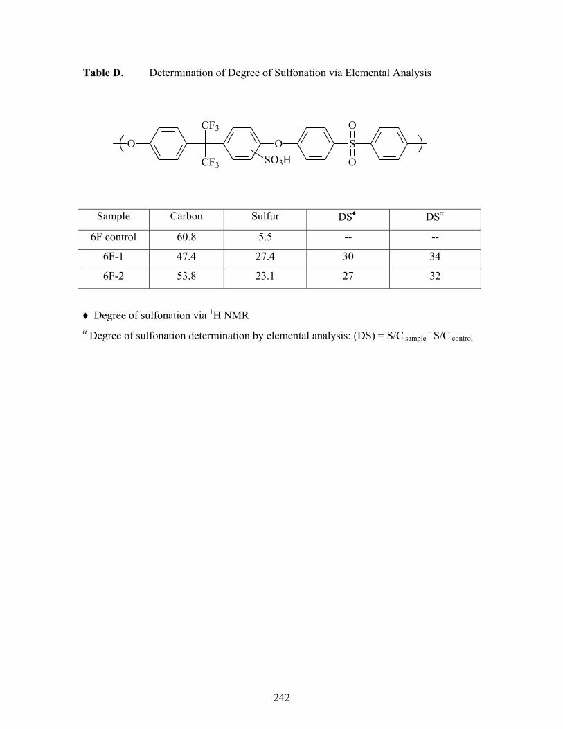
242
Table D. Determination of Degree of Sulfonation via Elemental Analysis
Sample Carbon Sulfur DS♦ DSα
6F control 60.8 5.5 -- --
6F-1 47.4 27.4 30 34
6F-2 53.8 23.1 27 32
♦ Degree of sulfonation via 1H NMR α Degree of sulfonation determination by elemental analysis: (DS) = S/C
sample – S/C
control
O S
O
O
O
CF3
CF3 SO3H

243
A plot of the actual degree of sulfonation verses the theoretical (expected) degree
of sulfonation based on chlorosulfonic acid concentration is shown in Figure E. This
study was performed only on 6F bisphenol A polymers. An efficiency value of
sulfonation was determined to be approximately 30% for chlorosulfonic acid based on
this plot. To investigate the influence, if any, chlorotrimethylsilane had on the efficiency
of sulfonation several reactions were performed in the absence of the protecting agent.
As seen in Figure E there is no distinguishable influence on the final degree of
sulfonation.
FIGURE E. Graph of sulfonation efficiency (actual degree of sulfonation) as a function
of chlorosulfonic acid concentration.
0
2 0
4 0
6 0
8 0
1 0 0
1 2 0
0 0 .5 1 1 .5 2 2 .5
6 F w / C T M S
6 F w / C T M S
6 F
6 F
T h e o r y
mole equivalent of chlorosulfonic acid
PercentSulfonation

244
Genova-Dimitrova et al.342 and Hamciuc et al.339 investigated other factors, such
as the influence of the sulfonating solvent, temperature, time and concentration while
sulfonating poly (arylene ethers) via chlorosulfonic acid. All of these variables were
determined to be significant on the final degree of sulfonation of the polymers. Hamciuc
et al.339 also investigated the sulfonation efficiency of chlorosulfonic acid as a function
of temperature and time. These researchers report a high of 60% efficiency when
sulfonating a poly (arylene ether sulfone) for 24 hours at 35 oC, but it is noted that high
temperature for shorter times did not match this value.
The process of generating the all sulfonated polymers involved several influential
factors with the dominate three being concentration, addition rate, and agitation rate. The
concentration of the polymer solution (i.e., poly(aryl ether sulfone) in the halogenated
solvent) had to be less than ten percent weight to volume(10% w/v). At higher
concentrations the solution quickly became opaque upon adding the chlorosulfonic acid
mixture. The opaqueness is attributed to the precipitation of the polymer. Another
controlling factor was the addition rate of the sulfonating agent. The chlorosulfonic acid
was always diluted with 10 mL dry solvent. Adding the chlorosulfonic acid solution
quickly (e.g. ~10ml of sulfonating solution within 10 minutes) or slowly (10ml within 60
minutes) results in precipitation of the polymer. The drop-wise addition of
chlorosulfonic acid within 25-30 minutes repeatedly provided the best (fairly
homogeneous) solutions. Fast agitation rates were also very important in maintaining the
polymer solutions. The difficulty in sustaining homogeneous solutions during
sulfonation may be a competing issue involving the changing solution polarity, etc.
during the addition of chlorosulfonic acid and also the changes to the polymer due to the
sulfonation.
The thermal stability of the three poly (arylene ether sulfones) was studied by
thermogravimetric analysis. The sulfonated polymers with low degrees of sulfonation
(i.e., less than 15%) exhibited comparable decomposition temperatures and similar
behaviors as those of their respective parent (control) polymers. These polymers showed
very high thermo-oxidative stabilities of over 500 oC for the 6F bisphenol A and biphenol
–based polymers; polymers containing bisphenol A showed stabilities up to ~ 480 oC. At
moderate degrees of sulfonation –between 25 – 50%, a two step degradation behavior
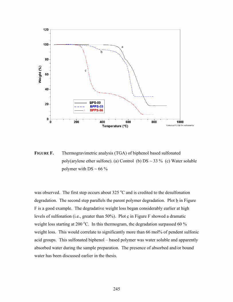
245
FIGURE F. Thermogravimetric analysis (TGA) of biphenol based sulfonated
poly(arylene ether sulfone). (a) Control (b) DS ~ 33 % (c) Water soluble
polymer with DS ~ 66 %
was observed. The first step occurs about 325 oC and is credited to the desulfonation
degradation. The second step parallels the parent polymer degradation. Plot b in Figure
F is a good example. The degradative weight loss began considerably earlier at high
levels of sulfonation (i.e., greater than 50%). Plot c in Figure F showed a dramatic
weight loss starting at 200 oC. In this thermogram, the degradation surpassed 60 %
weight loss. This would correlate to significantly more than 66 mol% of pendent sulfonic
acid groups. This sulfonated biphenol – based polymer was water soluble and apparently
absorbed water during the sample preparation. The presence of absorbed and/or bound
water has been discussed earlier in the thesis.
a b
c
ab
c

246
Conclusions
Three poly (arylene ether sulfones) based on bisphenol A, biphenol, and 6F
bisphenol A were prepared using dichlorodiphenyl sulfone in NMP via nucleophilic
aromatic substitution. These high molecular weight polymers were sulfonated with
chlorosulfonic acid derivatized by chlorotrimethylsilane in halogenated solvents at
ambient temperatures. This procedure did not show any evidence of chain cleavage or
branching during the mild electrophilic aromatic substitution reactions. The degree of
sulfonation was determined via 1H NMR spectroscopy and elemental analysis, and was
qualitatively monitored using FTIR. The degree of sulfonation was controlled by varying
the molar ratio of sulfonating agent to polymer, and an efficiency of sulfonation value of
about 30% was determined. Properties, such as solubility-- particularly methanol and
water solubility, and thermal stability, were influenced by the degree of sulfonation.
Sulfonated polymers with degrees of sulfonation up to 90% were achieved. The modified
polymers could produce flexible films from common solvents. However, precise
composition by post reaction methodologies were difficult, to impossible. The random
post-sulfonated materials were very different than the directly copolymerized systems.

247
Vita
William Lamont Harrison, son of Willie and Lugretta Harrison, was born on
March 12, 1973 in Laurinburg, NC. William has two sisters, Vonda and Tiffany. Before
graduating Scotland High School in June 1991, William met Dionne Ellerbe, who would
eventually become his wife. In August of the same year, he went to Winston-Salem State
University, and completed requirements for a B.S. in Chemistry in 1995, earning Magna
Cum Laude honors, with the assistance of an US Environmental Protection Agency
fellowship. During his matriculation at WSSU, he worked with many special scientists,
especially his department chair Professor Astor Herrell, who encouraged him to continue
his education. William entered Hampton University (VA) in the fall of 1995 with an
assistantship through the National Science Foundation. Professor Godson C. Nwokogu
advised him through his Master’s research project entitled “Synthesis and
Characterization of Polyarylate Copolymers based on Bisphenol A and Iso/Terephthalic
Acids via Melt Acidolysis”. William entered Virginia Polytechnic Institute and State
University in the fall of 1997 under the advisement of Professor James E. McGrath.
While at Virginia Tech, he enjoyed learning from many talented researchers and had the
opportunity to present at numerous national meetings. William enjoyed the happiness
received from his two children, Lamonte’ and Leah, and the time he took to volunteer
and work with many students in the surrounding communities. William research efforts
at Virginia Tech focused primarily the syntheses and characterization of poly (arylene
ethers), and earned him his Doctoral degree in Organic/Polymer Chemistry in December
2002. He is currently a post doctoral research associate in the department of chemistry at
Virginia Tech.


![Crystal structure of bis[bis(4-azaniumylphenyl) sulfone ......[bis(4,40-diazaniumylphenyl) sulfone] tetranitrate monohydrate}, the cations are conformationally similar, with comparable](https://static.fdocuments.us/doc/165x107/60b0786ebd8ffd67d34c0b4e/crystal-structure-of-bisbis4-azaniumylphenyl-sulfone-bis440-diazaniumylphenyl.jpg)


![Sulfone Metabolite of Sulindac Inhibits Mammary ... · Drug Synthesis. The sulfone metabolite [cis-5-fluoro-2-methyl-l(p-meth ylsulfonylbenzylidene)-3-indenylacetic acid] of sulindac](https://static.fdocuments.us/doc/165x107/5e615475b219221f465b2c4b/sulfone-metabolite-of-sulindac-inhibits-mammary-drug-synthesis-the-sulfone.jpg)
