Introduction to Artificial Intelligence Artificial Intelligence Section 4 Mr. Sciame.

ARTIFICIAL INTELLIGENCEAND PLC SYSTEMS
CHAPTERSIXTEEN
Computers can figure out all kinds of prob-lems, except the things in the world that justdon’t add up.
—James Magary
Industrial Text & Video Company 1-800-752-8398www.industrialtext.com

774
SECTION
5Advanced PLCTopics and Networks
Industrial Text & Video Company 1-800-752-8398www.industrialtext.com
CHAPTER
16Artificial Intelligence
and PLC Systems
Artificial intelligence (AI) is an area of computer science that has beenaround for some time. In fact, the conceptual design of AI was first developedin the early 1960s. The definition of artificial intelligence varies amongpeople in the computer industry, making the concept somewhat difficult toperceive and understand. In general, AI can be defined as the subfield ofcomputer science that encompasses the creation of computer programs tosolve tasks requiring extensive knowledge.
The software programs that form an AI system are developed using theknowledge of an expert person (or persons) in the field where the system willbe applied. For instance, a food-processing AI system that involves themaking and packaging of a food product will consist of knowledge obtainedfrom chemists, food technologists, packaging experts, maintenance person-nel, and others closely associated with the operation.
In this chapter, we will present AI techniques that can be implementedthrough a PLC-based process control system. These techniques will definethe methods for implementing AI into the process. The result will be a systemthat can successfully diagnose, control, and predict outcomes based onresident knowledge and program sophistication.
CHAPTER
HIGHLIGHTS
In previous chapters, we highlighted both simple and complex PLCapplications. In this chapter, we will present an area of PLC applications thatgoes one step beyond these—artificial intelligence. We will explain the basicsof artificial intelligence (AI) systems by explaining their organization andmethodology. We will also discuss how each of the three types of artificialintelligence systems—diagnostic, knowledge, and expert—work. Finally,we will present an example of an AI application to further explain how thesecomplex systems operate. After you finish learning about artificial intelli-gence, you will be ready to explore fuzzy logic, another advanced applicationthat involves PLCs.
16-1 INTRODUCTION TO AI SYSTEMS
16-2 TYPES OF AI SYSTEMS
An exact classification of the types of artificial intelligence systems is verydifficult to obtain because of the varying definitions of AI applications. Forthe purposes of this text, however, we will divide artificial intelligence intothree types of systems:
• diagnostic
• knowledge
• expert

775
CHAPTER
16Artificial Intelligence
and PLC SystemsSECTION
5Advanced PLCTopics and Networks
Industrial Text & Video Company 1-800-752-8398www.industrialtext.com
Each of these types of AI systems have similar characteristics, and in fact, thesystems evolve sequentially. As the systems become more sophisticated, thesize of the database grows and the extent of how the process data is compiledand interpreted increases.
DIAGNOSTIC SYSTEMS
Diagnostic AI systems are the lowest level of artificial intelligence imple-mentation. These systems primarily detect faults within an application, butthey do not try to solve them. For example, a diagnostic system can diagnosea pump fault by detecting a loss of tank pressure or by reading flow metervalues.
A diagnostic system reaches a fault conclusion through inferring techniquesbased on known facts (knowledge) introduced into its detection system. Thistype of AI is used in applications that have a small knowledge and databasestructure. Diagnostic systems typically make GO or NO GO decisions andsometimes provide information about the fault’s probable cause.
KNOWLEDGE SYSTEMS
A knowledge AI system is, in reality, an enhanced diagnostic system.Knowledge systems not only detect faults and process behaviors based onresident knowledge, but also make decisions about the process and/or theprobable cause of a fault.
In the batching system example mentioned in the diagnostic system section,a knowledge system would go beyond just diagnosing the fault. It would alsoprovide suggestions about probable faulty devices, as well as make a decisionabout whether to continue the process (if the fault is noncritical) or to shutdown (if the fault is critical). The system bases these decisions on itsprogrammed knowledge and a set of rules that defines each fault condition.
It is possible that the detection of a fault in the previous example could havebeen a false alarm. As part of its enhanced features, a knowledge systemchecks whether the elements signaling the fault condition (i.e., flow meter,pressure transducer) are operating correctly. It then compares these observa-tions (process feedback) with the procedures and measures based on thisinformation. For example, if a fault does occur and it is a valid noncriticalfault, the control system may issue continue process, stop after finished, andalert personnel commands.
EXPERT SYSTEMS
An expert AI system is the top of the line in AI-type applications; it has allof the capabilities of a knowledge system and more. An expert systemprovides an additional capability for examining process data using statistical

776
SECTION
5Advanced PLCTopics and Networks
Industrial Text & Video Company 1-800-752-8398www.industrialtext.com
CHAPTER
16Artificial Intelligence
and PLC Systems
analysis. The use of statistical data analysis lets the system predict outcomesbased on current process assessments. The outcome prediction may be adecision to continue a process in spite of a fault detection.
For the example used in the other two types of AI systems, an expert systemmay decide to continue the batching operation until the noncritical faultgenerates another fault. The system might arrive at this decision because theaverage pressure sensed in the mixing reactor tank is within tolerance limits(i.e., readings observed about the mean). Thus, the system continues thebatching operation in spite of the fact that the flow meter reported a loss offlow. The system then continues production and alerts personnel that pumpand flow meter feedback may have been lost.
The knowledge introduced into an expert system is more complex than in theother types of AI systems; therefore, expert systems generate more dataverification (feedback information). The decisions made by expert systemsalso require more sophisticated software programming, since their decisiontrees involve more options and attributes.
The implementation of an expert AI system requires not only extra program-ming effort but also more hardware capability. The total system will needmore transducers to check other transducers and field devices. Moreover, thePLC will require the use of two or more processors to implement the controland intelligence programs. The speed of the system must also be fast so thatit can operate in real time. Furthermore, the system’s memory requirementswill be larger, since knowledge data must be incorporated and stored into theAI system.
16-3 ORGANIZATIONAL STRUCTURE OF AN AI SYSTEM
A typical artificial intelligence system consists of three primary elements:
• a global database
• a knowledge database
• an inference engine
Figure 16-1 shows a block diagram of an AI system’s architecture. As thefigure illustrates, the AI system must receive its knowledge from a personwho thoroughly understands the process or machine being controlled. Thisindividual, called the expert, must communicate all information aboutsystem maintenance, fault causes, etc. to the knowledge engineer, the personresponsible for system implementation. The process of gathering data fromthe expert and transmitting it to the knowledge engineer is known asknowledge acquisition.

777
CHAPTER
16Artificial Intelligence
and PLC SystemsSECTION
5Advanced PLCTopics and Networks
Industrial Text & Video Company 1-800-752-8398www.industrialtext.com
Figure 16-1. Artificial intelligence system architecture.
GLOBAL DATABASE
The global database section of an AI system contains all of the availableinformation about the system being controlled. This information mainly dealswith the input and output data flow from the process. The global databaseresembles a storage area where information about the process is stored andupdated. The AI system can access the data in this area at any time to performstatistical analysis on historical process control data, which in turn can be usedto implement AI decisions.
The global database resides in the memory of the control system implement-ing the artificial intelligence. If a PLC is used to implement a diagnostic AIsystem, the global database will most likely be located in the storage area ofthe PLC’s data table. If a PLC is used in conjunction with a computer orcomputer module to implement an AI system, then the global database willprobably be located in the computer, the computer module’s memory, or ahard disk storage subsystem.
KNOWLEDGE DATABASE
The knowledge database section of an AI system stores the informationextracted from the expert. Like the global database, this database includesinformation about the process; however, it also stores information aboutfaults, along with their probable causes and possible solutions. Moreover, theknowledge database stores all of the rules governing the AI decisions to bemade. The more involved the AI system, the larger the knowledge database.
Knowledge DatabaseKnowledge representation,
specific knowledgeinformation
Global DatabaseMemory, system status
Inference EngineControl strategy,conflict resolution
User
ActionTaken
KnowledgeAcquisition
KnowledgeEngineer
Expert
FeedbackInformation
778
SECTION
5Advanced PLCTopics and Networks
Industrial Text & Video Company 1-800-752-8398www.industrialtext.com
CHAPTER
16Artificial Intelligence
and PLC Systems
Accordingly, the knowledge database of a diagnostic system is less complexthan that of a knowledge system; likewise, the knowledge database of aknowledge system is less sophisticated than that of an expert system. Theknowledge database is stored in the section of the system memory thatimplements the AI techniques.
INFERENCE ENGINE
An AI system’s inference engine is the place where all decisions are made.This section uses the information stored in the knowledge database to arriveat a decision and then execute all applicable rules and decisions about theprocess. The inference engine also constantly interacts with the globaldatabase to examine and test real-time and historical data about the process.
The inference engine usually resides in the main CPU (i.e., the one thatperforms the AI computations). However, in a PLC-based system, theinference engine may or may not be stored in the main CPU, dependingupon the system’s complexity (i.e., diagnostic, knowledge, or expert).
16-4 KNOWLEDGE REPRESENTATION
Knowledge representation is the way the complete artificial intelligencesystem strategy is organized—that is, how the knowledge engineer repre-sents the expert’s input. This representation is stored in the knowledgedatabase of the AI system. In rule-based knowledge representation, theexpert’s knowledge is transformed into IF and THEN/ELSE statements,which facilitate actions and decisions.
All control systems that implement artificial intelligence, whether diagnostic,knowledge, or expert, execute the control strategy (via the software controlprogram) in the inference engine. Whenever a decision must be made due toa fault or another situation, the inference engine refers to the knowledgerepresentation to obtain a decision about the probable cause. This decisionis the result of a group of software subroutines. Once the knowledge databasereaches an AI decision, the inference engine will determine the appropriatecourse of action. Depending on the control strategy formulation (mainprogram), the inference engine may, at this time, refer to the global databaseto verify data or obtain more information.
RULE-BASED KNOWLEDGE REPRESENTATION
Rule-based knowledge representation defines how the expert’sknowledge is used to make a decision. The rules used are either antecedent(IF something happens) or consequent (THEN take this action). For example,to the question, What causes the volume in the tank to drop?, the expert mayrespond with the answer, a malfunctioning tank system. The knowledge

779
CHAPTER
16Artificial Intelligence
and PLC SystemsSECTION
5Advanced PLCTopics and Networks
Industrial Text & Video Company 1-800-752-8398www.industrialtext.com
engineer may implement this information as the following rule: IF the volumeis less than the set point, THEN annunciate a system malfunction due to a lossof volume.
Rules can be as long and complex as needed for the process, and they usuallydefine the involvement of the AI system. For instance, a simple rule-basedsystem (few rules, not very complex) may formulate a simple diagnostic rule,such as:
IF the temperature is less than the set point, THEN open the steam valve
A more complex diagnostic formula would involve rules that depend onparent rules:
IF case 1, THEN ⎯ ELSE nothing⏐IF case 2, THEN ⎯ ELSE something
⏐IF case 3 ⎯ THEN nothing
•••
where each of the case conditions represents a particular measurement,comparison, or situation. Figure 16-2 illustrates a decision tree for formingAI rules.
Figure 16-2. Decision tree.
IF
THEN ELSE
IF
THEN ELSE
IF
THEN ELSE
IF
THEN ELSE
IF
THEN ELSE

780
SECTION
5Advanced PLCTopics and Networks
Industrial Text & Video Company 1-800-752-8398www.industrialtext.com
CHAPTER
16Artificial Intelligence
and PLC Systems
A slightly different degree of complexity occurs in a rule-based knowledgerepresentation when the rule has several probable causes. For example:
IF volume drops, THEN
valve failureor
pump failureor
feedback failure
⎧
⎨⎪⎪
⎩⎪⎪
In this case, the consequents must be further investigated to arrive at acomplete formal rule. The inference engine can use the consequents derivedin the knowledge representation to obtain a better definition of the problem’scause. Knowledge and expert AI systems use this process to provide ad-vanced decision-making capabilities.
EXAMPLE 16-1
A PLC-controlled box conveyor transports two sizes of boxes that arediverted to different palletizer operations according to their size. Asolenoid activates the diverter that sorts the boxes. Write the rules thata knowledge database could use to detect a possible cause for thesolenoid’s malfunction.
Figure 16-3. Knowledge database rules for conveyor fault.
SOLUTION
One of two factors can result in solenoid failure according to thesituation presented: coil burnout or mechanical damage. The condi-tions and causes in Figure 16-3 describe these two possible factorsthat could lead to a fault.
Rule #1
Result
Burned-out coil
Condition Cause
Excessive temperature is developed due to continuous high-current input
—Low line voltage causes failure to pull plunger
—High ambient temperature
—Mechanically blocked plunger
—Operations too rapid
Rule #2
Result
Mechanicaldamage
Condition Cause
Excessive force exerted on the plunger
—Overvoltage—Reduced load

781
CHAPTER
16Artificial Intelligence
and PLC SystemsSECTION
5Advanced PLCTopics and Networks
Industrial Text & Video Company 1-800-752-8398www.industrialtext.com
16-5 KNOWLEDGE INFERENCE
Knowledge inference is the methodology used for gathering and analyzingdata to draw conclusions. Knowledge inference occurs in the inference engineduring the execution of the main control strategy program. It also occurs inthe knowledge database during the comparison and computation of rulesolutions.
The system’s software program determines the approach used to derive AIsolutions. Operator interaction on control problems can enhance the solu-tion-finding process. For example, if the system detects a failure due to amisreading in an inspection system, it may alert the operator to the problemand advise him/her of probable causes. Furthermore, the system may wait forthe operator’s input (e.g., check for laser intensity in the receiver side todetermine if the laser beam is reflecting at the correct angle) and then use theoperator’s input to develop more intelligent solutions to the problem.
In small systems, knowledge inference occurs on a local basis. That is, thecontrol system houses the resident software for the inference engine. In large,distributed, intelligent systems, knowledge inference often occurs at a mainhost in the hierarchical system.
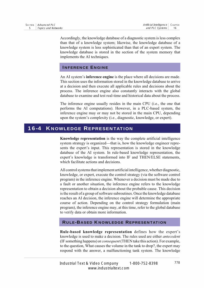
Remember that the degree of AI involvement in the system will determinehow much hardware is required (e.g., computer modules, powerful PLCs,small PLCs with personal computers, etc.). When all global databases are inconstant network communication, allowing knowledge inference informa-tion to be passed from one controller to another, the intelligent system is saidto have a blackboard architectural structure.
In all types of intelligent systems, certain methods of rule evaluation areused to implement knowledge inference. These methods include forwardchaining and backward chaining. Intelligent systems also analyze statisticalinformation as part of knowledge inferencing to obtain predictions aboutoutcomes.
BLACKBOARD ARCHITECTURE
Large, complex, distributed control systems involve the interaction of severalsubsystems, which continuously communicate with each other either directlyor over a local area network. When artificial intelligence is added to theselarge systems, system elements, such as knowledge inferencing and theglobal and knowledge databases, are distributed throughout the architectureof the control system. Whether or not each of the controllers in the networkhas a local inference engine, global database, and knowledge database
782
SECTION
5Advanced PLCTopics and Networks
Industrial Text & Video Company 1-800-752-8398www.industrialtext.com
CHAPTER
16Artificial Intelligence
and PLC Systems
depends on the degree of inferencing that occurs on a local basis. Blackboardarchitecture is the name given to this type of large system, which utilizesseveral subsystems containing local global and knowledge databases.
Figure 16-4 illustrates a blackboard configuration of an intelligent controlsystem. The PLCs at the subsystem level may contain computer modules,which help them perform inference engine computations. The hierarchy ofthe control system allows the supervisory PLC controller to poll each of thesubsystems and obtain all or part of their local global database information.The host computer element in this control structure holds the blackboard, thearea that stores all of the information obtained from the subsystems by thesupervisory PLC. The inference engine of the host element then implementsthe complex AI solution according to its knowledge inference about the totalcontrol system.
Figure 16-4. Example of blackboard architecture.
FORWARD CHAINING
Forward chaining is a method used to determine possible outcomes forgiven data inputs. Forward chaining inference engines typically receiveprocess information via the global database and monitor specific inputs to thecontrol system to determine the outcomes. For instance, in Example 16-1,forward chaining specifies the following consequences for a failed solenoid:a jammed conveyor or misplaced boxes in the two palletizers.
HostComputerSystem
Blackboard• Inference engine• Global database• Knowledge database
Local (PLC Systems)
• Inference engine• Global database• Knowledge database
Local (Supervisory PLC)
• Inference engine• Global database• Knowledge database
SupervisoryPLC System
PLCSystem
PLCSystem
PLCSystem
PLCSystem

783
CHAPTER
16Artificial Intelligence
and PLC SystemsSECTION
5Advanced PLCTopics and Networks
Industrial Text & Video Company 1-800-752-8398www.industrialtext.com
Two different types of fact searching occur within the forward chainingmethod: depth first and breadth first. Both searches deal with how theoutcome is obtained. A depth-first search, shown in Figure 16-5, evaluatesthe rules that form the knowledge database (A, B, C, etc.) on a priority basisgoing down the tree. In the conveyor example mentioned earlier, when thecontrol system detects the solenoid failure (A), it will evaluate a new rule tosee if jamming has occurred (B). If the conveyor has jammed, then the systemwill evaluate the consequences that can occur (e.g., material inside box maybreak or material could spill (D)).
1
2
3 4
5
6
87
A
C
F G
B
ED
IH
Figure 16-5. Forward chaining depth-first search.
In contrast, the breadth-first method evaluates each rule in the same level ofthe tree before proceeding to the next level down (see Figure 16-6). In ourconveyor example, a breadth-first evaluation of the rules means that afterthe solenoid failure (A) the system will check for a possible jam (B), then itwill check for palletizer misplacement (C), and so on.
A
C
F G
B
ED
IH
1
3
7 8
4
2
65
Figure 16-6. Forward chaining breadth-first search.

784
SECTION
5Advanced PLCTopics and Networks
Industrial Text & Video Company 1-800-752-8398www.industrialtext.com
CHAPTER
16Artificial Intelligence
and PLC Systems
BACKWARD CHAINING
STATISTICAL AND PROBABILITY ANALYSIS
EXAMPLE 16-2
A control system monitors and controls a cooker in a temperature loopwith specifications as shown in Figure 16-7. Indicate how AI can beadded to the system to detect real temperature problems. Also,indicate how the system can screen out false temperature faults.
Backward chaining is a method for finding the causes of an outcome.Referring to Example 16-1, the rule tables present backward chaininginformation—that is, causes for the solenoid failure outcome. Basically,backward chaining analyzes the consequences to obtain the antecedents.
Similar to forward chaining, backward chaining uses both the depth-first andbreadth-first search methods. In our conveyor example, after the solenoidfailure occurs, a backward chaining depth-first search will first check onecondition rule then check each possible cause of that condition. On the otherhand, a breadth-first search will first examine both of the condition rules andthen obtain the causes for each of the conditions.
Statistical analysis and probability play a large role in artificial intelligencesystems. These aspects of AI are particularly important in expert systems,which predict outcomes. The system’s global database stores the processinformation that will be used in the AI statistical analysis.
In Chapter 13, we explained how to interpret and obtain statistical data,such as the mean, mode, median, and standard deviation. These statisticalcomputations help determine a future outcome based on what is happening inthe current process. Decisions based on statistics can be related to theconsequences of the rules described in the knowledge representation. Forexample, just because a system detects an error fault does not mean that thefault actually occurred, even though the feedback data transducer devicesmay be operating correctly. Using statistical analysis, the inference enginemay decide not to advise personnel or apply the corresponding control to thefault, but instead to continue monitoring the situation more closely.
SOLUTION
Figure 16-7a shows a profile of temperature readings from thesystem. The PLC can monitor and accumulate temperature datacontinuously from time t0 to time t1 using FIFO instructions, storing thisdata in a storage area with a fixed number of registers (see Figure 16-7b). The program can also compute the mean, median, and standarddeviation of the current temperature readings.

785
CHAPTER
16Artificial Intelligence
and PLC SystemsSECTION
5Advanced PLCTopics and Networks
Industrial Text & Video Company 1-800-752-8398www.industrialtext.com
If a high-limit alarm occurs (see Figure 16-7c), a normal system wouldcontrol the cooker by adjusting its temperature loop. However, thetemperature fault may not have been caused by a temperature loopmalfunction; a noise spike near the temperature transducer couldhave caused it.
An intelligent system would detect this sudden temperature increaseby recognizing that it is well beyond the mean and median of thereadings for the t0 to t1 period, therefore exhibiting a large standard
Figure 16-7. (a) Profile of temperature readings, (b) FIFO storage method, and (c)high-limit alarm value in the example process.
High Limit
Low Limit
TimeTe
mpe
ratu
re
°C
Time
°C
t0 t1
High Limit
Low Limit
Time
Tem
pera
ture
°C
t0 t1
Temperature Out
Temperature In
(a)
(b)
(c)
Temperature at time t1
Temperature at time t0
Temperaturevalues stored
786
SECTION
5Advanced PLCTopics and Networks
Industrial Text & Video Company 1-800-752-8398www.industrialtext.com
CHAPTER
16Artificial Intelligence
and PLC Systems
P X Y P Y X P XP Y X P X P Y X P X
( / ) [ ( / )][ ( )][ ( / )][ ( )] [ ( / )][ ( )]
=+
where:
P Y X Y XP X X
P Y X Y XP X X
( / )( )
( / )
( )
==
=
=
the probability that occurs when has occurred the prior probability that has occurred
the conditional probability that occurs if does not occur
the prior probability that has not occurred
deviation. By implementing a rule that considers the statistics of theprocess, the AI system will ignore the false alarm and not add thetemperature reading value to the average calculations report. Further-more, the global database of the system will receive information, forfuture use, about the time of day, location, and level of the spikereading. The system will closely analyze the temperature increase incase it is a true alarm. It will use temperature rate of change compu-tations to help determine if it is a true fault.
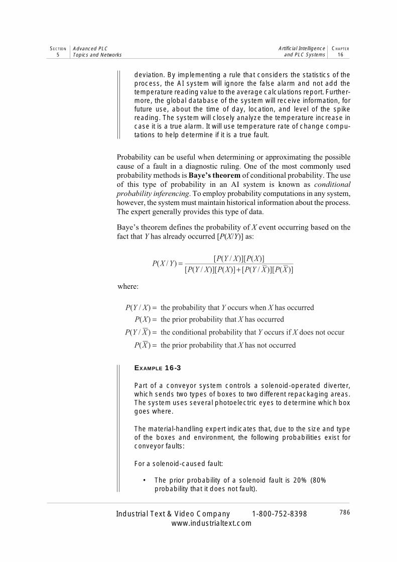
Probability can be useful when determining or approximating the possiblecause of a fault in a diagnostic ruling. One of the most commonly usedprobability methods is Baye’s theorem of conditional probability. The useof this type of probability in an AI system is known as conditionalprobability inferencing. To employ probability computations in any system,however, the system must maintain historical information about the process.The expert generally provides this type of data.
Baye’s theorem defines the probability of X event occurring based on thefact that Y has already occurred [P(X/Y)] as:
EXAMPLE 16-3
Part of a conveyor system controls a solenoid-operated diverter,which sends two types of boxes to two different repackaging areas.The system uses several photoelectric eyes to determine which boxgoes where.
The material-handling expert indicates that, due to the size and typeof the boxes and environment, the following probabilities exist forconveyor faults:
For a solenoid-caused fault:
• The prior probability of a solenoid fault is 20% (80%probability that it does not fault).

787
CHAPTER
16Artificial Intelligence
and PLC SystemsSECTION
5Advanced PLCTopics and Networks
Industrial Text & Video Company 1-800-752-8398www.industrialtext.com
• The probability that the boxes will go to the right placewhen the solenoid is faulty is 35%.
• The probability that the boxes will go to the right placewhen the solenoid is good is 60%.
For a photoeye-caused fault:
• The probability of a photoeye fault is 35% (65% prob-ability that it does not fault).
• The probability that the boxes go to the right place whenthe eye is faulty is 25%.
• The probability that the boxes go to the right place whenthe eye is good is 45%.
Find the most probable cause of a conveyor fault when the boxes aregoing to the right place.
SOLUTION
We can include the expert’s data in the knowledge representation bycalculating which element has a higher percentage probability ofhaving occurred. Using Baye’s theorem, the probability that the solenoidis faulty (S) even though the boxes are going to the right place (B) is:
P S B P B S P SP B S P S P B S P S
( / )[ ( / )][ ( )]
[ ( / )][ ( )] [ ( / )][ ( )]( . )( . )
( . )( . ) ( . )( . ). %
=+
=+
=
0 35 0 200 35 0 20 0 60 0 80
12 73
The probability that the photoeye is faulty (E) even though the boxesare going to the right place (B) is:
P E BP B E P E
P B E P E P B E P E( / )
[ ( / )][ ( )][ ( / )][ ( )] [ ( / )][ ( )]
( . )( . )( . )( . ) ( . )( . )
. %
=+
=+
=
0 25 0 350 25 0 35 0 45 0 65
23 03
The computations indicate that a photoeye fault is most likely to haveoccurred in the conveyor system. In this event, the operator should bealerted and the system temporarily halted. Also, the global databaseshould be updated with the statistics of the fault occurrence, so thatthis information can be used in the future.
788
SECTION5
Advanced PLCTopics and Networks
Industrial Text & Video Company 1-800-752-8398www.industrialtext.com
CHAPTER16
Artificial Intelligenceand PLC Systems
CONFLICT RESOLUTION
A conflict occurs when more than one rule is triggered at the same time in anAI system. Normally, a system starts executing rules based on the order ofoccurrence of the situation. However, when situations happen at the sametime, a conflict may occur in the system. For example, a system may receiveinformation indicating that a high temperature, a low pressure, and a flowobstruction have all occurred. These three situations, on their own or incombination, can trigger the following rule consequents:
Rule 1: IF high temperature, THEN start cooling procedure.
Rule 2: IF low pressure and flow obstruction, THEN openrelief valve in main supply pipe.
Rule 3: IF high temperature and low pressure, THEN openrelief valve in main supply pipe and alert personnel inthe area.
Therefore, the system must make a decision about which of these three rulesto implement. It must select the rule that exhibits the greater priority—in thiscase, rule 3. The expert provides the system with this information about thepriority of rule execution.
The example presented in this section illustrates the use of the methodologydescribed in the previous sections. For simplicity, we will not elaborate on thePLC program coding for the application, but we will describe the rules usedto define the knowledge representation.
The AI setup in this example is a diagnostic-level system implemented by aPLC-based control system. The method of rule evaluation is backwardchaining (i.e., once the system detects a fault, it searches for the cause of thefault). In the batching system, the control program implements AI faultdetection for only one of the two ingredients. The rules for the secondingredient are similar to the first ingredient.
DEFINITION OF THE PROCESS
Two ingredients, A and B, are to be mixed in the tank of the batching systemshown in Figure 16-8. Figures 16-9 through 16-12 show the flowcharts of theprocess, as well as the steam valve–versus–temperature relationships. Theprocess is as follows:
• A flow meter counts the number of pulses to monitor the amount ofthe ingredients in the tank (in gallons).
16-6 AI FAULT DIAGNOSTICS APPLICATION

789
CHAPTER16
Artificial Intelligenceand PLC Systems
SECTION5
Advanced PLCTopics and Networks
Industrial Text & Video Company 1-800-752-8398www.industrialtext.com
Figure 16-8. Batching system configuration.
Figure 16-9. Main control program flowchart.
Temp Switch TS1
Temp Switch TS2
Steam Valve
Temp Transducer
Auxiliary Valve
SolenoidValve B
SolenoidValve A
Meter BMeter A PumpB
PumpA
Pressure Transducer
Mixer Motor
Float Switch
DischargeSolenoid
Valve
Contacts
Start
End
Initalize andenter parameters
Batch controlroutine
Subroutine:print fault
Temperaturecontrol routine
Subroutine: checkcorrect operation
Subroutine that implements faultdetection using AI techniques

790
SECTION5
Advanced PLCTopics and Networks
Industrial Text & Video Company 1-800-752-8398www.industrialtext.com
CHAPTER16
Artificial Intelligenceand PLC Systems
Figure 16-10. Temperature and steamvalve relationship.
Figure 16-11. Temperature controlsubroutine.
Istemp at800°C
?
Open valveto 100%
Start
End
No
No
Time tocool to100°C
?
Set valve to 60%
No
Time toincreaseto 800°C
?
Yes
Yes
Set valve to 40%
Yes
Temperature vs. % of valve opening
60%
40%
Set Points
SP2
800°C
SP1
100°C
°C
100°C 800°C
Steam Valve
60%
100%
40%
Temperature Profile
800°C
100°C
°C
t1 t2

791
CHAPTER16
Artificial Intelligenceand PLC Systems
SECTION5
Advanced PLCTopics and Networks
Industrial Text & Video Company 1-800-752-8398www.industrialtext.com
Figure 16-12. Batching control routine.
No
Close Sol A,pump A OFF
Go to subroutine(check faults and print)
Open Sol B,pump B ON
Finish A?
Open Sol A,pump A ON
Start
End
No
Finish B?
No
Read gallon amount
StartPB pushed
?
Yes
Yes
Close Sol B,pump B OFF
Elevate to 800°Ctemp control
Mixer ON
Yes
Mix motor OFF
Delay for stable
Open discharge Sol
Mix timeelapsed?
FloatswitchOFF?
No
Yes
Yes
1
1
Close discharge Sol
No

792
SECTION5
Advanced PLCTopics and Networks
Industrial Text & Video Company 1-800-752-8398www.industrialtext.com
CHAPTER16
Artificial Intelligenceand PLC Systems
• A pump motor provides the necessary pressure to send the ingredientsthrough the line.
• Before any of the ingredients are poured into the tank, the temperatureinside the tank should be 100°C. A solenoid opens a steam valve to40% to achieve the proper temperature in the tank.
• A load cell pressure transducer reads the volume inside the tank. Itdetects whether an ingredient is entering the tank, serving as afeedback device in the event of a faulty signal.
• After the two ingredients are in the tank, the temperature must be at800°C before mixing can occur. The steam valve opens to 100% untilthe temperature reaches 800°C, then it remains at 60% open tomaintain 800°C.
• Two thermoswitches detect the two desired temperatures (100°C and800°C) and serve as feedback in case of a fault.
• A steam valve heats up the tank. A temperature transducer controls thetemperature, maintaining it at the desired level.
• A motor agitates the two ingredients.
• An auxiliary valve disposes of the ingredients in the event that they arenot mixed properly.
• When the mixing is finished, a discharge valve drains the desiredsolution (mixture) into the next step of the process. The steam valvereturns to 40% open to cool the temperature in the tank to 100°C forthe next batch.
• A float switch detects an empty tank.
PROCESS CONTROL FAULT DETECTION
Fault detection in the system occurs during three major stages of the process:
1. when the ingredients are being poured
2. during the elevation of temperature
3. during the cooling of the tank
For each of these stages, the system can provide fault–versus–possible causeinformation. It detects the fault through feedback information from eachof the controlling and measuring devices. It then verifies this fault informa-tion by comparing it with feedback data from additional control devices.Table 16-1 shows the control and feedback devices used to perform thesystem check.

793
CHAPTER16
Artificial Intelligenceand PLC Systems
SECTION5
Advanced PLCTopics and Networks
Industrial Text & Video Company 1-800-752-8398www.industrialtext.com
RULE DEFINITIONS
Based on the process control description and the possible failures, the systemhas the rules described in Table 16-2. These rules specify actions based onprocess occurrences and measurements.
Given the AI system’s rules, we can define a set of faults F, representing thepossible malfunctions, as:
F n in i, , for to to 2= =0 9 1
where:
ni
== = =
rule number type of fault (1 critical, 2 noncritical)
We can divide the set of faults (Fn,i) into two subsets—critical faults (Fn,1) andnoncritical faults (Fn,2):
F F F nn i n n, , ,∈ =1 2 1 or for to 9
The actions taken for critical faults are abort batch process, alert operator ofcritical fault, open auxiliary valve, and inform operator of possible faultydevices. The actions taken for noncritical faults are alert the operator,continue process and stop at end of batch, and inform operator of possiblefaulty devices.
APPLICATION SUMMARY
Applying AI techniques to a control system usually involves addinghardware and software to the system. The complexity of the AI programvaries depending on how much fault detection is desired. The previousexample presented only the rules for one ingredient. Although the rules forthe second ingredient would be similar, the control system would still haveto be programmed with them, and this could be time consuming.
seciveDlortnoC kcabdeeF esopruP
evlaV erusserpdnahctiwstimiLrecudsnart
noitautcadioneloskcehCevlavni
pmuP erusserpdnastcatnoCrecudsnart
noitarepopmupkcehC
retemwolF recudsnarterusserP wolftneidergnikcehCevlavmaetS hctiwserutarepmeT evlavmaetskcehC
Table 16-1. Control and feedback devices used in batching system.

794
SECTION5
Advanced PLCTopics and Networks
Industrial Text & Video Company 1-800-752-8398www.industrialtext.com
CHAPTER16
Artificial Intelligenceand PLC Systems
Table 16-2. Batching system rules.
seluR
1 .ssecorperitnehtiwdeecorP.KOnoitarepoNEHT,tluafonsierehtFI
2 .erusserpkcehcNEHT,evlavehtnitluafasierehtFIeunitnoC.hctiwstimilehtnitluafasierehtNEHT,KOsierusserpFI
.potsdnassecorppotS.evlavehtnitluafasierehtNEHT,KOtonsierusserpFI
.tluafxif;evlavyrailixuanepo;rotarepotreladnassecorp
3 .erusserpdaerNEHT,pmupehtnitluafasierehtFI.tcatnocs’pmupehtnitluafasierehtNEHT,KOsierusserpFI
.potsdnassecorpeunitnoCpotS.pmupehtnitluafasierehtNEHT,KOtonsierusserpFI
.tluafxif;evlavyrailixuanepo;rotarepotreladnassecorp
4 .erusserpdaerNEHT,retemehtnitluafasierehtFIeunitnoC.retemwolfehtnitluafasierehtNEHT,KOsierusserpFI
.potsdnassecorp.evlavro/dnapmupehtnitluafasierehtNEHT,KOtonsierusserpFI
.tluafxif;evlavyrailixuanepo;rotarepotreladnassecorppotS
5 .erusserpdaerNEHT,evlavdnaretemehtnitluafasierehtFItimilro/dnaretemwolfehtnitluafasierehtNEHT,KOsierusserpFI
.potsdnassecorpeunitnoC.hctiws.pmupro/dnaevlavehtnitluafasierehtNEHT,KOtonsierusserpFI
.tluafxif;evlavyrailixuanepo;rotarepotreladnassecorppotS
6 .erusserpdaerNEHT,pmupdnaretemehtnitluafasierehtFIpmupro/dnaretemehtnitluafasierehtNEHT,KOsierusserpFI
.tluafxif;potsdnassecorpeunitnoC.stcatnoc.evlavro/dnapmupehtnitluafasierehtNEHT,KOtonsierusserpFI
.tluafxif;evlavyrailixuanepo;rotarepotreladnassecorppotS
7 daerNEHT,retemwolfdnaevlavdnapmupehtnitluafasierehtFI.erusserp
ro/dnaretemwolfehtnitluafasierehtNEHT,KOsierusserpFI.potsdnassecorpeunitnoC.hctiwstimilro/dnapmup
.pmupro/dnaevlavehtnitluafasierehtNEHT,KOtonsierusserpFI.tluafxif;evlavyrailixuanepo;rotarepotreladnassecorppotS
8 008otknatehtfognitaehehtgnirudtluafasierehtFI ° si2STdnaC.recudsnarterutarepmetehtnitluafasierehtNEHT,emittesaniNO
.potsdnassecorpeunitnoCtluafasierehtNEHT,doirepemittesehtnidnopsertonseod2STFI
yrailixuanepo;rotarepotreladnassecorppotS.evlavmaetsehtni.tluafxif;evlav
9 001otknatehtfogniloocehtgnirudtluafasierehtFI ° si1STdnaC.recudsnarterutarepmetehtnitluafasierehtNEHT,emittesaniNOtluafasierehtNEHT,doirepemittesehtnidnopsertonseod1STFI
.evlavmaetsehtnitonodyeht;dehsinifsihctabehtecnis,lacitircnonerastluafhtoB
.sdnammochctabtrobaeriuqer

795
CHAPTER16
Artificial Intelligenceand PLC Systems
SECTION5
Advanced PLCTopics and Networks
Industrial Text & Video Company 1-800-752-8398www.industrialtext.com
KEY
TERMS
We could add intelligence to the system by storing data from the process (e.g.,how many times the pump has been turned ON, the contact status feedbackto the system, how many times the valve has been turned ON and OFF, whichlimit switch responded, etc). This data, in conjunction with informationabout the last time and type of failure, when and how it was fixed, and whenthe last maintenance was performed, would allow the system to identifywhether two possible causes generated a single fault. The global databasewould store this additional information, allowing the system to make deci-sions based on the probabilities assigned or calculated throughout several pastprocess performances. Undoubtedly, the more intelligent a system is, themore productive it will be. Additional intelligence means less downtime anda safer process environment.
artificial intelligence (AI)backward chainingBaye’s theoremblackboard architecturediagnostic AI systemexpert AI systemforward chainingglobal databaseinference engineknowledge AI systemknowledge databaseknowledge inferenceknowledge representationrule-based knowledge representation

Industrial Text & Video Company 1-800-752-8398www.industrialtext.com
This page intentionally left blank.