Artificial hinged-wing bird with active torsion and ... · 28th International Congress of the...
9
28 th International Congress of the Aeronautical Sciences Artificial hinged-wing bird with active torsion and partially linear kinematics Wolfgang Send ANIPROP GbR, Sandersbeek 20, D-37085 Goettingen Markus Fischer Festo GmbH & Co. KG, D-73734 Esslingen Kristof Jebens JNTech GbR, D-71116 Gaertringen Rainer Mugrauer Effekt- Technik GmbH, D-72667 Schlaitdorf Agalya Nagarathinam JNTech GbR, D-71116 Gaertringen Felix Scharstein ANIPROP GbR, Sandersbeek 20, D-37085 Goettingen c/o ANIPROP GbR, Göttingen, Germany Key words: Biologically-inspired flight, Experimental facilities and techniques, Active torsion
Transcript of Artificial hinged-wing bird with active torsion and ... · 28th International Congress of the...
28th International Congress of the Aeronautical Sciences
Artificial hinged-wing bird with active torsion and partially linear kinematics
Wolfgang Send ANIPROP GbR, Sandersbeek 20, D-37085 GoettingenMarkus Fischer Festo GmbH & Co. KG, D-73734 EsslingenKristof Jebens JNTech GbR, D-71116 GaertringenRainer Mugrauer Effekt- Technik GmbH, D-72667 SchlaitdorfAgalya Nagarathinam JNTech GbR, D-71116 Gaertringen Felix Scharstein ANIPROP GbR, Sandersbeek 20, D-37085 Goettingen
c/o ANIPROP GbR, Göttingen, Germany
Key words: Biologically-inspired flight, Experimental facilities and techniques, Active torsion
2 Wolfgang Send et al.
An artificial bird is introduced which was developed using two new features in biologically-inspired flight, active torsion and partially lin-ear kinematics. Active torsion rests on well established theoretical predictions in unsteady aerodynamics. The concept of partially linear kinematics is inspired by zoological observations on flying locusts. When the wings flap upwards, the servomotor for the active torsion
turns the outer wing from a positive angle of incidence within a short fraction of the flapping period into a negative angle of inci-dence. Between the turning points the angle of torsion remains constant. Numerical calculations confirm the expected benefits compared to passive torsion.
Abstract
Nature has done an ingenious job of integrating the generation of lift and thrust. Its engine for producing thrust without a single rotating part is the flapping wing. Leonardo da Vinci designed the first human flapper with hinged wings. Many attempts were made in the past to mimic birds’ flight with technical constructions, among them the remarkable early work of Lippisch [1] before 1930. Birds, insects and fishes apply the same basic mechanism. This mechanism is an inherent property of the aerodynamic equations derived from the conservation laws for momentum, mass and energy in fluid mechan-ics. The coupled bending and torsional motion of a 3D wing reduces to a coupled pitching and plunging motion in 2D.
The physics of this motion has widely been investigated. A recently published paper gives a thorough and comprehensive overview of the history and of progress and challenges in flapping-wing aerody-namics [2]. The discovery of the mechanism dates back to 1924 [3] and was a spin-off during research on airplane flutter. This extremely dangerous phenomenon of high technical importance for aircraft sta-bility physically rests on the same mathematical description as animal propulsion does. It is merely the reverse side of the same coin. The one side is producing thrust with a flapping wing to move forward, the other one is winning energy with oscillating wings from a uniform
onset flow. Both modes simply differ in the amplitude ratio of the two constituent degrees of freedom pitching and plunging, bending and torsion respectively. High plunging at small pitching produces thrust, low plunging with high pitching extracts energy. The vicinity of transition from one mode to the other one is a domain of almost com-plete energy conversion up to 90 % according to basic results in unsteady aerodynamics. Large birds probably are able to fly in this range due to their very low drag. The beneficial use of energy extrac-tion from an airstream with flapping wings was first investigated in the early 1980s [4] and later extended to the so-called stroke-wing engine for water currents tested in several projects up to 150 kW installed power.
The primary motivation for our research project was a better under-standing of the coupled bending and torsional motion and its optimi-zation for potential technical applications. Believing that thrust generation in nature during its long history of evolutionary steps has reached a high level of efficiency we tried to reveal some of its secrets. Our artificial bird serves as technology carrier and demon-strator for encouraging and stimulating research in both directions of producing thrust and using this particular technique for renewable energy resources.
1 Introduction
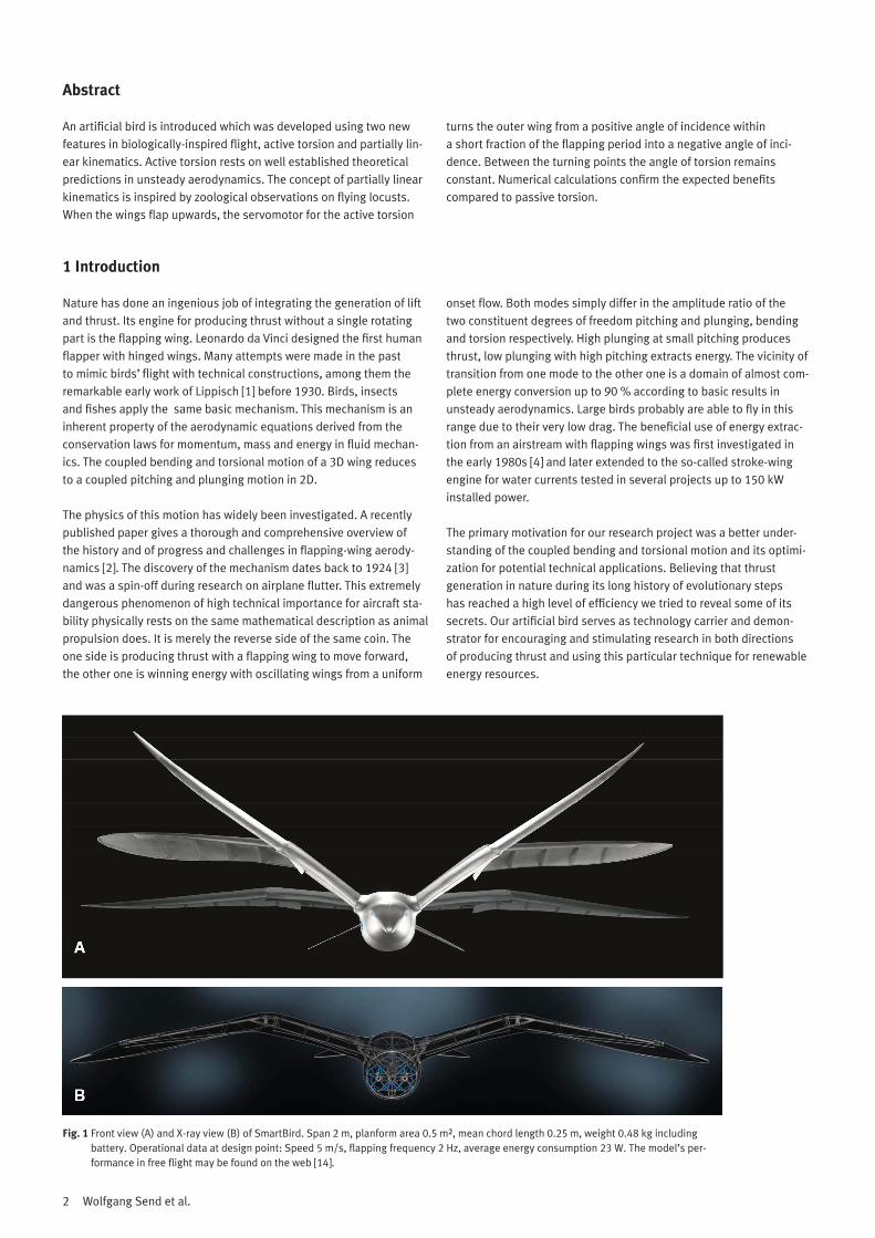
Fig. 1 Front view (A) and X-ray view (B) of SmartBird. Span 2 m, planform area 0.5 m², mean chord length 0.25 m, weight 0.48 kg including battery. Operational data at design point: Speed 5 m/s, flapping frequency 2 Hz, average energy consumption 23 W. The model’s per-formance in free flight may be found on the web [14].
3Artificial hinged-wing bird
Fig. 1 shows three positions of the articulated wings which are super-imposed (A). The X-ray view in the lower part displays the mechanical function (B). The wing consists of a two-part inner wing spar with an axis suspension at the wing root inside the fuselage, a trapezoidal hinge as is found in a larger format in excavators, and an outer wing spar. Via the trapezoidal hinge, a 1:3 transmission ratio is achieved. The inner wing generates lift, the outer wing across the trapezoidal hinge generates thrust. Both the spars of the inner wing and the outer wing are torsionally stiff. The active torsion is achieved by a servomo-tor at the end of the outer wing which twists the wing against the spar via the outmost rib of the wing. When SmartBird flaps the wing upwards, the servomotor for the active torsion turns the outer wing from a positive angle of incidence within a short fraction of the flap-ping period into a negative angle of incidence. During these points of turn the angle of torsion remains constant. Through this partially linear motion the flow on the profile is optimally utilized for the gener-ation of thrust. The battery, motor and gear, the crank mechanism and the control and regulating electronics are housed in the fuselage. The external rotor motor flaps the wings up and down via a two-stage spur gearing with a 1:45 reduction of speed. The motor is equipped
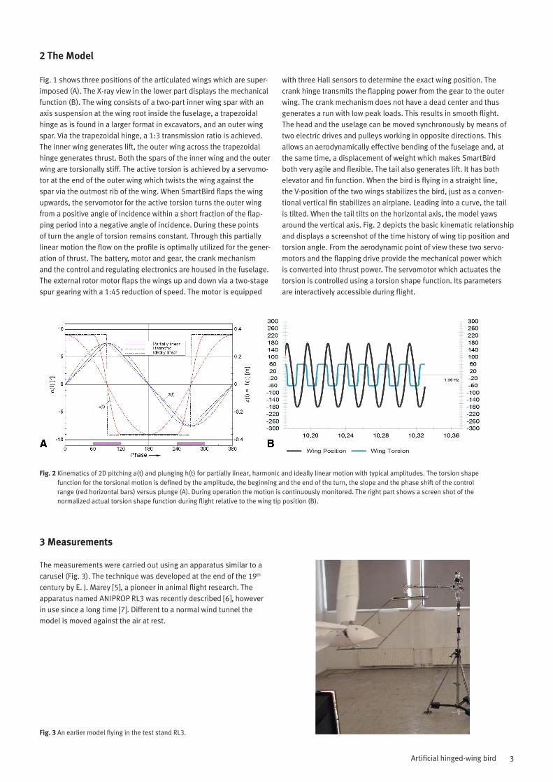
with three Hall sensors to determine the exact wing position. The crank hinge transmits the flapping power from the gear to the outer wing. The crank mechanism does not have a dead center and thus generates a run with low peak loads. This results in smooth flight. The head and the uselage can be moved synchronously by means of two electric drives and pulleys working in opposite directions. This allows an aerodynamically effective bending of the fuselage and, at the same time, a displacement of weight which makes SmartBird both very agile and flexible. The tail also generates lift. It has both elevator and fin function. When the bird is flying in a straight line, the V-position of the two wings stabilizes the bird, just as a conven-tional vertical fin stabilizes an airplane. Leading into a curve, the tail is tilted. When the tail tilts on the horizontal axis, the model yaws around the vertical axis. Fig. 2 depicts the basic kinematic relationship and displays a screenshot of the time history of wing tip position and torsion angle. From the aerodynamic point of view these two servo-motors and the flapping drive provide the mechanical power which is converted into thrust power. The servomotor which actuates the torsion is controlled using a torsion shape function. Its parameters are interactively accessible during flight.
2 The Model
Fig. 2 Kinematics of 2D pitching a(t) and plunging h(t) for partially linear, harmonic and ideally linear motion with typical amplitudes. The torsion shape function for the torsional motion is defined by the amplitude, the beginning and the end of the turn, the slope and the phase shift of the control range (red horizontal bars) versus plunge (A). During operation the motion is continuously monitored. The right part shows a screen shot of the normalized actual torsion shape function during flight relative to the wing tip position (B).
The measurements were carried out using an apparatus similar to a carusel (Fig. 3). The technique was developed at the end of the 19th
century by E. J. Marey [5], a pioneer in animal flight research. The apparatus named ANIPROP RL3 was recently described [6], however in use since a long time [7]. Different to a normal wind tunnel the model is moved against the air at rest.
3 Measurements
Fig. 3 An earlier model flying in the test stand RL3.
4 Wolfgang Send et al.
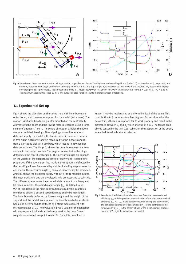
Fig. 4 shows the side view on the central hub with inner boom and outer boom, which serves as support for the model (red square). The motion is initiated by a towing motor mounted on the central hub. A lever tows the boom and the towing force is recorded using a force sensor of a range +/- 50 N. The centre of rotation Lz holds the boom mounted with ball bearings. Nine slip rings transmit operational data and supply the model with electric power instead of a battery in free flight. Angular velocity is measured via the signals coming from a bar-coded disk with 180 bars, which results in 360 position data per rotation. The hinge Gk allows the outer boom to rotate from vertical to horizontal position. The angular sensor inside the hinge determines the centrifugal angle â. The measured angle bU depends on the weight of the support, its centre of gravity and its geometric properties. If the boom is set into motion, the support is deflected by the centrifugal force. Because all quantities including angular velocity are known, the measured angle âU can also theoretically be predicted. Angle âT shows the predicted value. Without a lifting model mounted, the measured angle and the predicted angle are expected to coincide. The difference determines the error which is inherent to subsequent lift measurements. The aerodynamic angle âaero is defined to be 90° at rest. Besides the main contributions to âT by the quantities mentioned above, a second correction may briefly be mentioned. The inner boom is deflected by its own weight and the weight of the support and the model. We assumed the inner boom to be an elastic beam and determined its stiffness by a static measurement with increasing loads at Gk. The evaluation gives a value for the deflection without external load and can be interpreted as the boom’s own weight concentrated in a point load at Gk. Once this point load is
known it may be recalculated as uniform line load of the beam. This contribution to âT amounts to a few degrees. For very low velocities below 2 m/s these assumptions fail to work properly and result in the difference between âT and âU which shows Fig. 4 (B). The failure prob-ably is caused by the thin steel cables for the suspension of the boom, when their tension is almost released.
3.1 Experimental Set-up
Fig. 4 Side view of the experimental set-up with geometric properties and forces. Gravity force and centrifugal force (index “z”) on inner boom FG , support FS and model FM determine the angle of the outer boom (A). The measured centrifugal angle âU is expected to coincide with the theoretically determined angle âT if no lifting model is present (B). The aerodynamic angle âaero must show 90° at rest and 0° for 100 % lift in horizontal flight. L = 2.17 m, dV + hS = 1.25 m. The maximum speed u0 exceeds 10 m/s. The turquoise step function counts the total number of rotations.
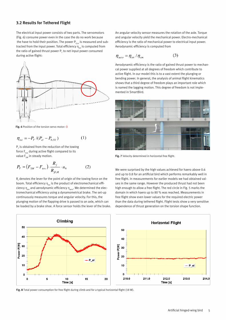
Fig. 5 Aerodynamic efficiency haero is computed from the measured total efficiency çtot and the previous determination of the electromechanical efficiency çem· Pel – P0,sv is the power consumed during the active flight. The almost constant power consumption P0,sv of the control servomo-tors given by Uel x Iel in the steady phase of the measurement amounts to about 5 W. U0 is the velocity of the model.
5Artificial hinged-wing bird
The electrical input power consists of two parts. The servomotors (Fig. 6) consume power even in the case the do no work because the have to hold their position. The power P0,sv is measured and sub-tracted from the input power. Total efficiency çtot is computed from the ratio of gained thrust power PT to net input power consumed during active flight:
PT is obtained from the reduction of the towingforce Ftow during active flight compared to itsvalue FSM in steady motion.
Rf denotes the lever for the point of origin of the towing force on the boom. Total efficiency çtot is the product of electromechanical effi-ciency çem and aerodynamic efficiency çaero. We determined the elec-tromechanical efficiency using a dynamometrical brake. The set-up continuously measures torque and angular velocity. For this, the plunging motion of the flapping drive is passed to an axle, which can be loaded by a brake shoe. A force sensor holds the lever of the brake.
An angular velocity sensor measures the rotation of the axle. Torque and angular velocity yield the mechanical power. Electro-mechanical efficiency is the ratio of mechanical power to electrical input power. Aerodynamic efficiency is computed from
Aerodynamic efficiency is the ratio of gained thrust power to mechan-cal power supplied at all degrees of freedom which contribute to active flight. In our model this is to a vast extent the plunging or bending power. In general, the analysis of animal flight kinematics shows that a third degree of freedom plays an important role which is named the lagging motion. This degree of freedom is not imple-mented in SmartBird.
We were surprised by the high values achieved for haero above 0.6 and up to 0.8 for an artificial bird which performs remarkably well in free flight. In measurements for earlier models we had obtained val-ues in the same range. However the produced thrust had not been high enough to allow a free flight. The red circle in Fig. 5 marks the domain in which haero up to 80 % was reached. Measurements in free flight show even lower values for the required electric power than the data during tethered flight. Flight tests show a very sensitive dependence of thrust generation on the torsion shape function.
3.2 Results for Tethered Flight
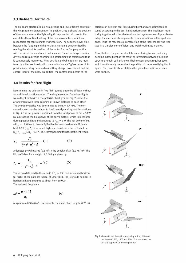
Fig. 6 Position of the torsion servo motor: O
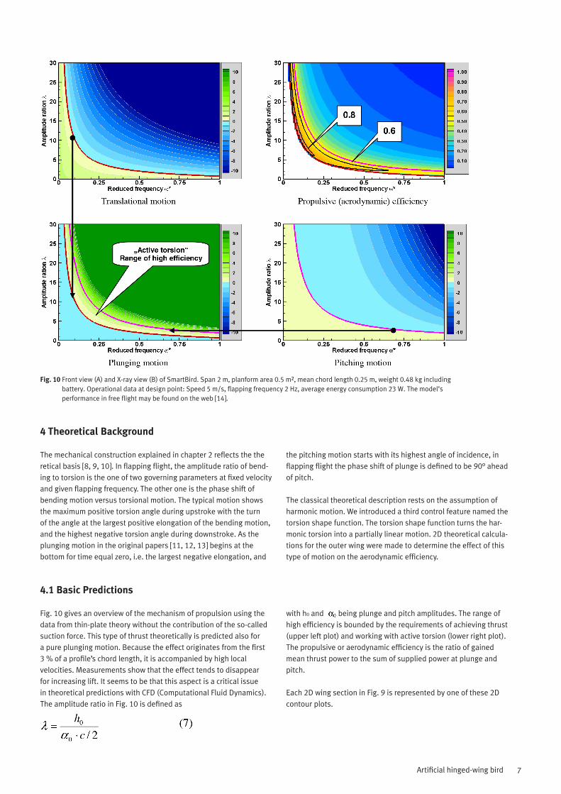
Fig. 7 Velocity determined in horizontal free flight.
Fig. 8 Total power consumption for free flight during climb and for a typical horizontal flight (18 W).
6 Wolfgang Send et al.
The on-board electronics allows a precise and thus efficient control of the wing’s torsion dependent on its position. Fig. 6 shows the position of the servo motor at the right wing tip. A powerful microcontroller calculates the optimal setting of the two servomotors, which are responsible for controlling the wing torsion. The sequence over time between the flapping and the torsional motion is synchronized by reading the absolute position of the motor for the flapping motion with the aid of the mentioned Hall sensors. The active hinged torsion drive requires a precise coordination of flapping and torsion and thus is continuously monitored. Wing position and wing torsion are moni-tored by a bi-directional radio communication via ZigBee protocol. It provides operating data such as battery charge, power input and the control input of the pilot. In addition, the control parameters of the
torsion can be set in real time during flight and are optimized and tuned according to the best flight performance. This intelligent moni-toring together with the electronic control system makes it possible to adapt the mechanical components to new situations within split sec-onds. Thus the mechanical construction of the flight model was real-ized in a simpler, more efficient and weightoptimized manner.
Nevertheless, the precise absolute data of wing torsion and wing bending in free flight as the result of interaction between fluid and structure remain still unknown. Their measurement requires tools which continuously determine the position of the whole flying bird in space. For theoretical calculations the given kinematic input data were applied.
3.3 On-board Electronics
Determining the velocity in free flight turned out to be difficult without an additional position system. The simple solution for indoor flights was a flight path with a characteristic background. Fig. 7 shows the arrangement with three columns of known distance to each other. The average velocity was determined to be u0 = 4.7 m/s. The con-sumed power may be related to basic aerodynamic quantities as done in Fig. 5. The net power is obtained from the total power of Pel = 18 W by subtracting the bias power of the servo motors, which is measured during passive flight and amounts to P0,sv = 5 W. The net power of Pel – P0,sv = 13 W has to be multiplied by the measured total efficiency htot 0.25 (Fig. 5) in tethered flight and results in a thrust force FT = çtot(Pel – P0,sv )/u0 = 0.7 N. The corresponding thrust coefficient reads:
A denotes the wing area (0.5 m²), r the density of air (1.2 kg/m³). The lift coefficient for a weight of 0.48 kg is given by:
These two data lead to the ratio CL / CD o 7 in free sustained horizon-tal flight. These data are typical of SmartBird. The Reynolds number in horizontal flight amounts to about Re = 80,000. The reduced frequency
ranges from 0.3 to 0.45. c represents the mean chord length (0.25 m).
3.4 Results for Free Flight
Fig. 9 Kinematics of the articulated wing at four different positions 0°, 90°, 180° and 270°. The motion of the torso is opposite to the wing motion
7Artificial hinged-wing bird
Fig. 10 Front view (A) and X-ray view (B) of SmartBird. Span 2 m, planform area 0.5 m², mean chord length 0.25 m, weight 0.48 kg including battery. Operational data at design point: Speed 5 m/s, flapping frequency 2 Hz, average energy consumption 23 W. The model’s performance in free flight may be found on the web [14].
The mechanical construction explained in chapter 2 reflects the the retical basis [8, 9, 10]. In flapping flight, the amplitude ratio of bend-ing to torsion is the one of two governing parameters at fixed velocity and given flapping frequency. The other one is the phase shift of bending motion versus torsional motion. The typical motion shows the maximum positive torsion angle during upstroke with the turn of the angle at the largest positive elongation of the bending motion, and the highest negative torsion angle during downstroke. As the plunging motion in the original papers [11, 12, 13] begins at the bottom for time equal zero, i.e. the largest negative elongation, and
the pitching motion starts with its highest angle of incidence, in flapping flight the phase shift of plunge is defined to be 90° ahead of pitch.
The classical theoretical description rests on the assumption of harmonic motion. We introduced a third control feature named the torsion shape function. The torsion shape function turns the har-monic torsion into a partially linear motion. 2D theoretical calcula-tions for the outer wing were made to determine the effect of this type of motion on the aerodynamic efficiency.
4 Theoretical Background
Fig. 10 gives an overview of the mechanism of propulsion using the data from thin-plate theory without the contribution of the so-called suction force. This type of thrust theoretically is predicted also for a pure plunging motion. Because the effect originates from the first 3 % of a profile’s chord length, it is accompanied by high local velocities. Measurements show that the effect tends to disappear for increasing lift. It seems to be that this aspect is a critical issue in theoretical predictions with CFD (Computational Fluid Dynamics). The amplitude ratio in Fig. 10 is defined as
with h0 and being plunge and pitch amplitudes. The range of high efficiency is bounded by the requirements of achieving thrust (upper left plot) and working with active torsion (lower right plot). The propulsive or aerodynamic efficiency is the ratio of gained mean thrust power to the sum of supplied power at plunge and pitch.
Each 2D wing section in Fig. 9 is represented by one of these 2D contour plots.
4.1 Basic Predictions
8 Wolfgang Send et al.
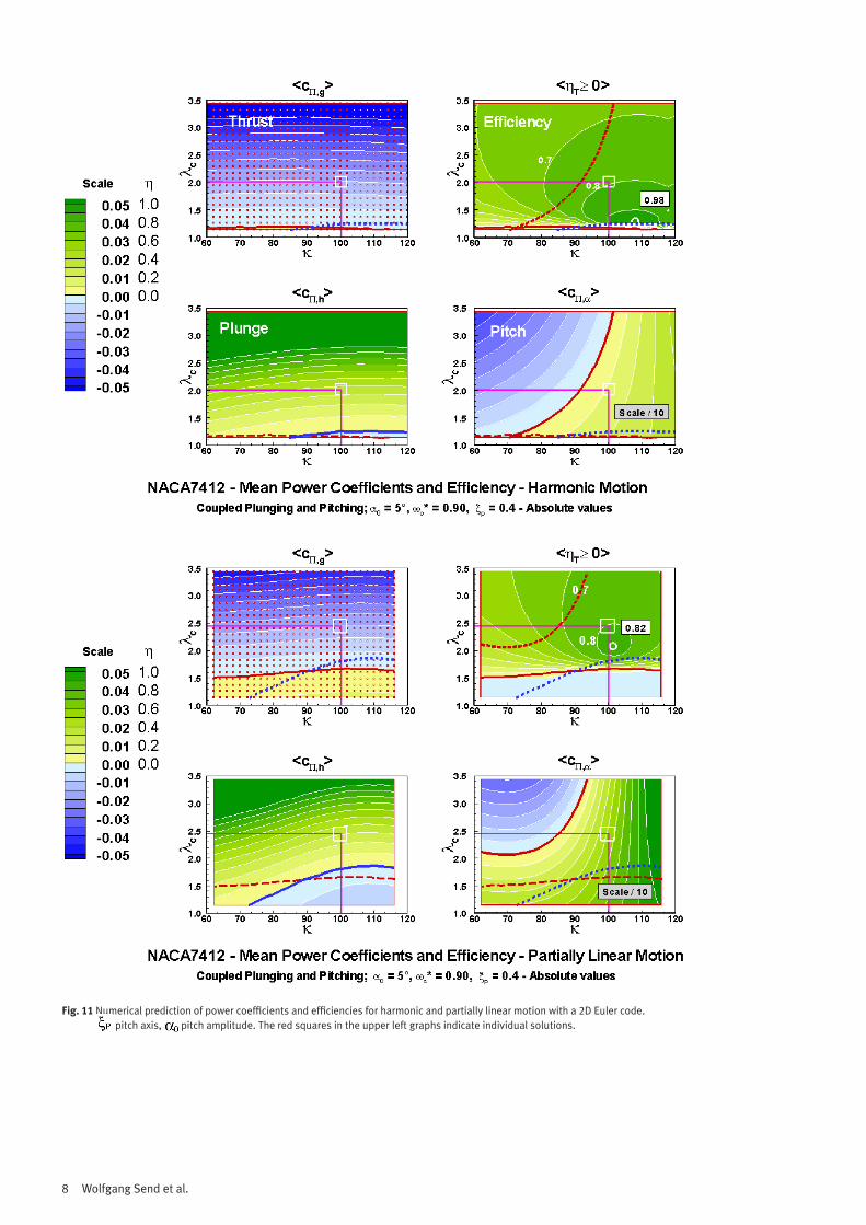
Fig. 11 Numerical prediction of power coefficients and efficiencies for harmonic and partially linear motion with a 2D Euler code. pitch axis, pitch amplitude. The red squares in the upper left graphs indicate individual solutions.
9Artificial hinged-wing bird
The basic predictions based on thin plate theory in Fig. 10 can well be compared to the numerical calculations using a CFD tool. Fig. 11 shows the result for harmonic motion and partially linear kinematics. The two figures differ in their definition of amplitude ratio and reduced frequency.
Data in Fig. 10 are normalized by the square of the pitch amplitude, in Fig. 11 absolute data are displayed. The data refer to the earlier model which is depicted in Fig. 3. The model performed as well as SmartBird except that its wing section was smaller. SmartBird allows for a still lower speed of 4.7 m/s instead of 5 m/s.
The design point (haero =0.8, k = 100°) is selected for a comparison between harmonic and partially linear motion. The amplitude ratio for harmonic motion is much smaller, i.e. the pitch amplitude much higher, than in the case of partially linear kinematics. The fairly wide plateau of high efficiency in Fig. 11 was not found during the flight tests. In summary the observations showed a very sensitive depend-ence on phase shift and amplitude ratio similar to the narrow range in Fig. 10.
4.2 Predictions Based on CFD
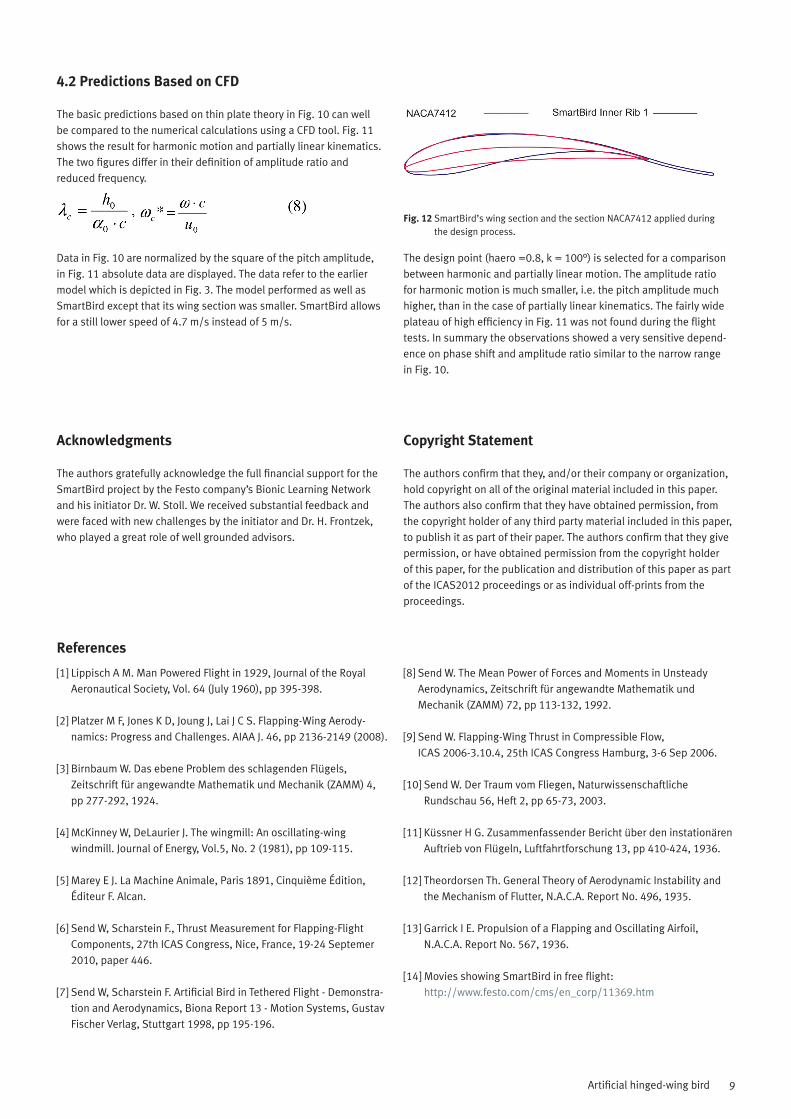
Fig. 12 SmartBird’s wing section and the section NACA7412 applied during the design process.
Copyright Statement
The authors confirm that they, and/or their company or organization, hold copyright on all of the original material included in this paper. The authors also confirm that they have obtained permission, from the copyright holder of any third party material included in this paper, to publish it as part of their paper. The authors confirm that they give permission, or have obtained permission from the copyright holder of this paper, for the publication and distribution of this paper as part of the ICAS2012 proceedings or as individual off-prints from the proceedings.
Acknowledgments
The authors gratefully acknowledge the full financial support for the SmartBird project by the Festo company’s Bionic Learning Network and his initiator Dr. W. Stoll. We received substantial feedback and were faced with new challenges by the initiator and Dr. H. Frontzek, who played a great role of well grounded advisors.
[1] Lippisch A M. Man Powered Flight in 1929, Journal of the Royal Aeronautical Society, Vol. 64 (July 1960), pp 395-398.
[2] Platzer M F, Jones K D, Joung J, Lai J C S. Flapping-Wing Aerody-namics: Progress and Challenges. AIAA J. 46, pp 2136-2149 (2008).
[3] Birnbaum W. Das ebene Problem des schlagenden Flügels, Zeitschrift für angewandte Mathematik und Mechanik (ZAMM) 4, pp 277-292, 1924.
[4] McKinney W, DeLaurier J. The wingmill: An oscillating-wing windmill. Journal of Energy, Vol.5, No. 2 (1981), pp 109-115.
[5] Marey E J. La Machine Animale, Paris 1891, Cinquième Édition, Éditeur F. Alcan.
[6] Send W, Scharstein F., Thrust Measurement for Flapping-Flight
Components, 27th ICAS Congress, Nice, France, 19-24 Septemer 2010, paper 446.
[7] Send W, Scharstein F. Artificial Bird in Tethered Flight - Demonstra-tion and Aerodynamics, Biona Report 13 - Motion Systems, Gustav Fischer Verlag, Stuttgart 1998, pp 195-196.
[8] Send W. The Mean Power of Forces and Moments in Unsteady Aerodynamics, Zeitschrift für angewandte Mathematik und Mechanik (ZAMM) 72, pp 113-132, 1992.
[9] Send W. Flapping-Wing Thrust in Compressible Flow, ICAS 2006-3.10.4, 25th ICAS Congress Hamburg, 3-6 Sep 2006.
[10] Send W. Der Traum vom Fliegen, Naturwissenschaftliche Rundschau 56, Heft 2, pp 65-73, 2003.
[11] Küssner H G. Zusammenfassender Bericht über den instationären Auftrieb von Flügeln, Luftfahrtforschung 13, pp 410-424, 1936.
[12] Theordorsen Th. General Theory of Aerodynamic Instability and the Mechanism of Flutter, N.A.C.A. Report No. 496, 1935.
[13] Garrick I E. Propulsion of a Flapping and Oscillating Airfoil, N.A.C.A. Report No. 567, 1936.
[14] Movies showing SmartBird in free flight: http://www.festo.com/cms/en_corp/11369.htm
References