Artificial evolution of the morphology and kinematics in a ... · Artificial evolution of the...
18
IOP PUBLISHING BIOINSPIRATION &BIOMIMETICS Bioinsp. Biomim. 2 (2007) 65–82 doi:10.1088/1748-3182/2/4/002 Artificial evolution of the morphology and kinematics in a flapping-wing mini-UAV E de Margerie, J B Mouret, S Doncieux and J-A Meyer SIMA Dpt, ISIR, Universit´ e Pierre et Marie Curie, 104 av. Pdt Kennedy, 75016 Paris, France E-mail: [email protected] Received 31 May 2007 Accepted for publication 17 September 2007 Published 5 November 2007 Online at stacks.iop.org/BB/2/65 Abstract Birds demonstrate that flapping-wing flight (FWF) is a versatile flight mode, compatible with hovering, forward flight and gliding to save energy. This extended flight domain would be especially useful on mini-UAVs. However, design is challenging because aerodynamic efficiency is conditioned by complex movements of the wings, and because many interactions exist between morphological (wing area, aspect ratio) and kinematic parameters (flapping frequency, stroke amplitude, wing unfolding). Here we used artificial evolution to optimize these morpho-kinematic features on a simulated 1 kg UAV, equipped with wings articulated at the shoulder and wrist. Flight tests were conducted in a dedicated steady aerodynamics simulator. Parameters generating horizontal flight for minimal mechanical power were retained. Results showed that flight at medium speed (10–12 m s −1 ) can be obtained for reasonable mechanical power (20 W kg −1 ), while flight at higher speed (16–20 m s −1 ) implied increased power (30–50 W kg −1 ). Flight at low speed (6–8 m s −1 ) necessitated unrealistic power levels (70–500 W kg −1 ), probably because our simulator neglected unsteady aerodynamics. The underlying adaptation of morphology and kinematics to varying flight speed were compared to available biological data on the flight of birds. (Some figures in this article are in colour only in the electronic version) 1. Introduction In order to achieve sustained horizontal flight, human flying machines usually rely on a fixed wing and a powered propeller such as an airplane or on powered rotating wings like in helicopters. On the other hand, birds, bats and insects—i.e., actively flying animals—use flapping-wing flight (FWF) to produce the lift and thrust forces needed for forward flight. The reasons why biological and technical worlds have retained different solutions may be of both historical (e.g., contingency) and structural (e.g., material constraints) nature. In particular, it appears that • Continually rotating mechanical joints—on which propellers and rotors are based in human technology— do not exist in animals at the macroscopic, morphological level. Skeletal joints would belong to the category of rotating joints, but the dependence on muscles and tendons as force and torque effectors limits their angular rotation. Hence, only reciprocating movements between skeleton elements are possible in animals. As a consequence of the historical, contingent constraint of inheriting a muscle- based activation system, propellers or rotating wings for active flight are beyond the reachable phenotypes of extant animals. • Articulated, moving wings as necessitated by FWF are hard to design for human flight. On a man-lifting scale, with usual aeronautical materials such as wood, steel, aluminium or even newer composite materials, FWF is a tremendous aerodynamic, mechanical and structural challenge for current technology. Although several ‘ornithopters’ have been constructed in the last 100 years, even the most recent designs (DeLaurier 1999) remain marginally efficient compared to classical fixed wing or rotor designs. As a result, the great potential of FWF demonstrated by animals in terms of speed range or manoeuvrability, though attractive, remains beyond the achievable goals of today’s human aerial transportation prospect. 1748-3182/07/040065+18$30.00 © 2007 IOP Publishing Ltd Printed in the UK 65
Transcript of Artificial evolution of the morphology and kinematics in a ... · Artificial evolution of the...

IOP PUBLISHING BIOINSPIRATION & BIOMIMETICS
Bioinsp. Biomim. 2 (2007) 65–82 doi:10.1088/1748-3182/2/4/002
Artificial evolution of the morphology andkinematics in a flapping-wing mini-UAVE de Margerie, J B Mouret, S Doncieux and J-A Meyer
SIMA Dpt, ISIR, Universite Pierre et Marie Curie, 104 av. Pdt Kennedy, 75016 Paris, France
E-mail: [email protected]
Received 31 May 2007Accepted for publication 17 September 2007Published 5 November 2007Online at stacks.iop.org/BB/2/65
AbstractBirds demonstrate that flapping-wing flight (FWF) is a versatile flight mode, compatible withhovering, forward flight and gliding to save energy. This extended flight domain would beespecially useful on mini-UAVs. However, design is challenging because aerodynamicefficiency is conditioned by complex movements of the wings, and because many interactionsexist between morphological (wing area, aspect ratio) and kinematic parameters (flappingfrequency, stroke amplitude, wing unfolding). Here we used artificial evolution to optimizethese morpho-kinematic features on a simulated 1 kg UAV, equipped with wings articulated atthe shoulder and wrist. Flight tests were conducted in a dedicated steady aerodynamicssimulator. Parameters generating horizontal flight for minimal mechanical power wereretained. Results showed that flight at medium speed (10–12 m s−1) can be obtained forreasonable mechanical power (20 W kg−1), while flight at higher speed (16–20 m s−1) impliedincreased power (30–50 W kg−1). Flight at low speed (6–8 m s−1) necessitated unrealisticpower levels (70–500 W kg−1), probably because our simulator neglected unsteadyaerodynamics. The underlying adaptation of morphology and kinematics to varying flightspeed were compared to available biological data on the flight of birds.
(Some figures in this article are in colour only in the electronic version)
1. Introduction
In order to achieve sustained horizontal flight, human flyingmachines usually rely on a fixed wing and a powered propellersuch as an airplane or on powered rotating wings like inhelicopters. On the other hand, birds, bats and insects—i.e.,actively flying animals—use flapping-wing flight (FWF) toproduce the lift and thrust forces needed for forward flight.The reasons why biological and technical worlds have retaineddifferent solutions may be of both historical (e.g., contingency)and structural (e.g., material constraints) nature. In particular,it appears that
• Continually rotating mechanical joints—on whichpropellers and rotors are based in human technology—do not exist in animals at the macroscopic, morphologicallevel. Skeletal joints would belong to the category ofrotating joints, but the dependence on muscles and tendonsas force and torque effectors limits their angular rotation.Hence, only reciprocating movements between skeleton
elements are possible in animals. As a consequence ofthe historical, contingent constraint of inheriting a muscle-based activation system, propellers or rotating wings foractive flight are beyond the reachable phenotypes of extantanimals.
• Articulated, moving wings as necessitated by FWF arehard to design for human flight. On a man-lifting scale,with usual aeronautical materials such as wood, steel,aluminium or even newer composite materials, FWF isa tremendous aerodynamic, mechanical and structuralchallenge for current technology. Although several‘ornithopters’ have been constructed in the last 100 years,even the most recent designs (DeLaurier 1999) remainmarginally efficient compared to classical fixed wing orrotor designs. As a result, the great potential of FWFdemonstrated by animals in terms of speed range ormanoeuvrability, though attractive, remains beyond theachievable goals of today’s human aerial transportationprospect.
1748-3182/07/040065+18$30.00 © 2007 IOP Publishing Ltd Printed in the UK 65
E de Margerie et al
Although FWF seems rather impractical on a man-lifting scale,which is also illustrated by the fact that extant flying animalsrarely exceed 10 kg in mass, the recent technological field ofunmanned aerial vehicles (UAVs) may find in FWF solutionsto challenging flight dynamics problems. As small size isa determining factor, research efforts on FWF are mostlyfocused on micro-UAVs (insect to small bird sized: 1–100 g)and mini-UAVs (medium to large bird sized: 0.1–10 kg). Atthese sizes, FWF has the potential to allow unique flightdynamics abilities, as demonstrated by the performance offlying animals:
• FWF is versatile. Depending on specific size and weight,flying animals can hover, fly forward at varying speedsand glide or soar to save energy. These flight regimesare selected according to daily activities such as foraging,observation or migration. In many small species, bothhelicopter and airplane-like abilities are merged into asingle, extended flight domain.
• Active articulated wings and asymmetrical flappingprovide very high manoeuvrability, especially useful inobstructed spaces, as demonstrated by perching birds thatfly among tree branches for example.
• Reciprocating wing movements allow flying animals touse favourable unsteady aerodynamics, at least duringhovering and slow flight (Norberg 1990). For example,one well-known unsteady effects is the ‘delayed stall’,which can increase the airfoil maximal lift up to 50%when the wing’s angle of attack is suddenly increased(Ellington 1984, Ellington et al 1996).
Drawing inspiration from natural flyers, one of the maininterests in transposing FWF to small UAVs is the ability toobtain an extended flight-mode range. Namely, a hovering andvery slow flight appears useful for exploration and observationin obstructed or urban areas, while a medium to high-speedhorizontal flight at low energetic cost, which is not wellachieved by helicopters, is necessary to cover large distances.Moreover, the ability to soar in ascending air currents is asupplementary key feature for saving energy.
Although the perspective of implementing these threeflight modes on a single UAV is very attractive, the maindrawback in using FWF, as mentioned above, is the highdifficulty of designing a mechanically and aerodynamicallyfunctional flapping wing, because of the large number ofinteracting parameters such as morphological characteristics,degrees of freedom and kinematic data associated with thewing’s parts.
In an attempt to overcome these difficulties, we usedartificial evolution (AE) to explore the range of functionalwing morphologies and kinematics for a simulated bird-like mini-UAV. AE is a ‘trial and error’ optimizationmethod inspired by Darwinian natural selection. It maycall upon several numerical optimization procedures suchas ‘genetic algorithms’, ‘evolution strategies’ and others(Goldberg 1989), which are used in engineering, artificialintelligence and biology to solve complex problems (for anAE application to biological morphology, see de Margerie et al(2006)). Compared to classical knowledge-driven engineering
methods, AE has the main advantage that it does not needa comprehensive high-level knowledge of the consideredproblem. In our case, only the basic laws of aerodynamics needto be implemented in a simulator, to make the generation ofvarious FWF solutions possible. By selecting the best amongsuch randomly generated solutions, by randomly recombiningand mutating them, and by testing the ‘offspring’ solutionsagain, AE can generate satisfactory optimized solutions tointricate problems, with minimal initial knowledge. This canbe useful for solving the FWF problem because one onlyneeds to know rather general aerodynamic laws to test anyAE-produced wing morphology, or any flapping movement,in a flight simulator.
The present work is part of the ROBUR project (Doncieuxet al 2004) that aims at designing an outdoor bird-like mini-UAV of 1–2 m wingspan, with adaptive locomotion modesand abilities required for a true decisional autonomy suchas obstacle avoidance (Muratet et al 2005), localization andmapping (Angeli et al 2006) and energy management (Barateet al 2006). Here, we focus on wing morphology andmovements and use AE to find morphological and kinematicparameters providing flapping flight at minimal energetic cost.These parameters mainly include the wing area, the wingaspect ratio, the flapping frequency, the stroke amplitudeand the angles of attack. As a first stepping stone, beforelater considering turning, ascending or aerobatic flight, weconcentrated the present work on forward horizontal flight atvarying speeds (6–20 m s−1), for an approximately 1 kg bird-like UAV.
A few previous works have used AE to optimize FWF,but with notable differences from the present work. Sallesand Schiele (2004), for instance, optimized the movementof a small rigid wing inspired by a hawkmoth’s wing,manipulated at low Reynolds number by a robotic arm, usinga genetic algorithm. Van Breugel and Lipson (2005) usedan evolutionary algorithm to optimize the lift produced bya simulated 50–310 g four-wing ornithopter. Although notusing AE, Rakotomamonjy et al (2004) used an optimizationalgorithm (nonlinear programming) on a neural networkcontrolling the kinematics of a simulated 30 g micro-UAV,in order to maximize the lift forces. Beyond differences inthe UAV’s mass, our work differs from these previous studiesin the fact that we simultaneously optimize the kinematicsand the wing morphology (size and shape) of our UAV. Toour knowledge, the work of Shim et al (2004) is the onlyother study evolving both the morphology and kinematics ofbird- or bat-sized FWF UAVs. However, their optimizationprocess does not consider energy consumption—their fitnesscriterion being a sum of flight speed and hovering time—andaccordingly embeds their study in a different perspective tiedto artificial life and virtual worlds and thus is less realistic andapplicable to real UAVs than ours.
2. Methods
2.1. UAV morphology and kinematics
Freely inspired by bird morphology, our simulated UAV hadtwo symmetrical wings and a central tail, as described in
66
Artificial evolution of the morphology and kinematics in a flapping-wing mini-UAV
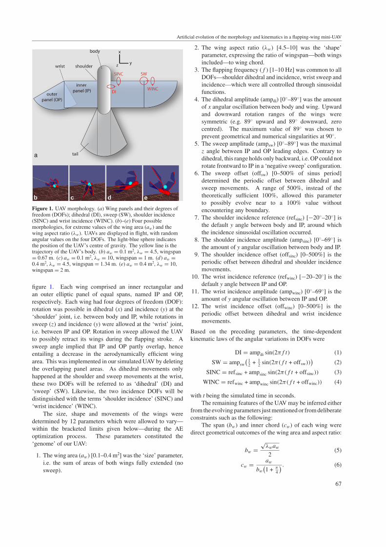
Figure 1. UAV morphology. (a) Wing panels and their degrees offreedom (DOFs); dihedral (DI), sweep (SW), shoulder incidence(SINC) and wrist incidence (WINC). (b)–(e) Four possiblemorphologies, for extreme values of the wing area (aw) and thewing aspect ratio (λw). UAVs are displayed in flight, with randomangular values on the four DOFs. The light-blue sphere indicatesthe position of the UAV’s centre of gravity. The yellow line is thetrajectory of the UAV’s body. (b) aw = 0.1 m2, λw = 4.5, wingspan= 0.67 m. (c) aw = 0.1 m2, λw = 10, wingspan = 1 m. (d) aw =0.4 m2, λw = 4.5, wingspan = 1.34 m. (e) aw = 0.4 m2, λw = 10,wingspan = 2 m.
figure 1. Each wing comprised an inner rectangular andan outer elliptic panel of equal spans, named IP and OP,respectively. Each wing had four degrees of freedom (DOF):rotation was possible in dihedral (x) and incidence (y) at the‘shoulder’ joint, i.e. between body and IP, while rotations insweep (z) and incidence (y) were allowed at the ‘wrist’ joint,i.e. between IP and OP. Rotation in sweep allowed the UAVto possibly retract its wings during the flapping stroke. Asweep angle implied that IP and OP partly overlap, henceentailing a decrease in the aerodynamically efficient wingarea. This was implemented in our simulated UAV by deletingthe overlapping panel areas. As dihedral movements onlyhappened at the shoulder and sweep movements at the wrist,these two DOFs will be referred to as ‘dihedral’ (DI) and‘sweep’ (SW). Likewise, the two incidence DOFs will bedistinguished with the terms ‘shoulder incidence’ (SINC) and‘wrist incidence’ (WINC).
The size, shape and movements of the wings weredetermined by 12 parameters which were allowed to vary—within the bracketed limits given below—during the AEoptimization process. These parameters constituted the‘genome’ of our UAV:
1. The wing area (aw) [0.1–0.4 m2] was the ‘size’ parameter,i.e. the sum of areas of both wings fully extended (nosweep).
2. The wing aspect ratio (λw) [4.5–10] was the ‘shape’parameter, expressing the ratio of wingspan—both wingsincluded—to wing chord.
3. The flapping frequency (f ) [1–10 Hz] was common to allDOFs—shoulder dihedral and incidence, wrist sweep andincidence—which were all controlled through sinusoidalfunctions.
4. The dihedral amplitude (ampdi) [0◦–89◦] was the amountof x angular oscillation between body and wing. Upwardand downward rotation ranges of the wings weresymmetric (e.g. 89◦ upward and 89◦ downward, zerocentred). The maximum value of 89◦ was chosen toprevent geometrical and numerical singularities at 90◦.
5. The sweep amplitude (ampsw) [0◦–89◦] was the maximalz angle between IP and OP leading edges. Contrary todihedral, this range holds only backward, i.e. OP could notrotate frontward to IP in a ‘negative sweep’ configuration.
6. The sweep offset (offsw) [0–500% of sinus period]determined the periodic offset between dihedral andsweep movements. A range of 500%, instead of thetheoretically sufficient 100%, allowed this parameterto possibly evolve near to a 100% value withoutencountering any boundary.
7. The shoulder incidence reference (refsinc) [−20◦–20◦] isthe default y angle between body and IP, around whichthe incidence sinusoidal oscillation occurred.
8. The shoulder incidence amplitude (ampsinc) [0◦–69◦] isthe amount of y angular oscillation between body and IP.
9. The shoulder incidence offset (offsinc) [0–500%] is theperiodic offset between dihedral and shoulder incidencemovements.
10. The wrist incidence reference (refwinc) [−20–20◦] is thedefault y angle between IP and OP.
11. The wrist incidence amplitude (ampwinc) [0◦–69◦] is theamount of y angular oscillation between IP and OP.
12. The wrist incidence offset (offwinc) [0–500%] is theperiodic offset between dihedral and wrist incidencemovements.
Based on the preceding parameters, the time-dependentkinematic laws of the angular variations in DOFs were
DI = ampdi sin(2πf t) (1)
SW = ampsw
(12 + 1
2 sin(2π(f t + offsw)))
(2)
SINC = refsinc + ampsinc sin(2π(f t + offsinc)) (3)
WINC = refwinc + ampwinc sin(2π(f t + offwinc)) (4)
with t being the simulated time in seconds.The remaining features of the UAV may be inferred either
from the evolving parameters just mentioned or from deliberateconstraints such as the following:
The span (bw) and inner chord (cw) of each wing weredirect geometrical outcomes of the wing area and aspect ratio:
bw =√
λwaw
2(5)
cw = aw
bw
(1 + π
4
) . (6)
67
E de Margerie et al
The body of the UAV was a cylinder with rounded tips(figure 1). Its length (lb) was proportional to the wing chord,and its radius (rb) was a function of the wing area, such thatthe body cross-section was proportional to the wing area:
lb = 4
3cw (7)
rb =√
aw
10. (8)
The tail area (at) was proportional to the wing area. The tailparts extending laterally beyond body sides were raised at 45◦
around the x-axis to provide some lateral stability to the UAVthrough a V-shaped tail surface:
at = aw
2. (9)
Tail position relative to the body was not allowed to changeand remained constant in all experiments. A control of thetail should further increase our artificial bird stability, but wepreferred not to include one, to rely on passive stability asmuch as possible.
The masses of the UAV elements were determined asfollows:
Considering that the wing mass would represent asignificant part of the total mass in a real FWF UAV, andconsidering that we aim at designing an approximately 1 kgflyer, the body mass (mb) was set to
mb = 0.5 kg. (10)
The wing mass (mw, for both wings) depended on the wingarea through an isometric relationship inspired by Greenewalt(1975). The tail mass (mt) was estimated through a similarrelationship:
mw = 2(aw)1.5 (11)
mt = (at )1.5. (12)
The masses of wings and tail were concentrated in theirrespective leading edges and uniformly distributed along thespan. The mass distribution within the body was such that thewhole UAV’s centre of gravity (CG) was located at about 25%of wing chord when the wings were fully extended.
The chosen ranges and laws of variation of our parameterscan now be compared to biological data.
Starting from the hard constraint that the body of ourUAV had a 0.5 kg mass, we found several species with similarmasses in the data of Magnan (1922, in Greenewalt (1962)).These species, among which are Hooded Crow (Corvuscornix), Shearwater (Calonectris diomedea) or Marsh-Harrier(Circus aeruginosus), have wing areas ranging from 0.13 to0.23 m2, except some ‘duck-model’ fast-flying species such asShoveler (Anas clypeata) or Coot (Fulica atra), which havewing areas as low as 0.06 m2. Choosing a range of (0.1–0.4) foraw covered the whole biological size range with the same mass,except the smallest, highly loaded duck-styled flyers, whichcan be considered as high-speed flight specialists, differingfrom our versatile UAV objective. As a direct outcome ofthe wing area, the wing loading of our UAV (the ratio oftotal mass to wing area) could range from 2.6 for maximal
aw to 5.7 kg m−2 for minimal aw. According to Greenewalt(1975, p 16), this range covers the natural wing loadings ofall sampled groups, including raptors [Falconiformes], owls[Strigiformes], herons [Ardeidae] and bats of comparablemasses, except the highly loaded ducks and shorebirds. Inthe latter groups, wing loading usually attains 6–10 kg m−2,while Auks [Alcidae] can attain even higher wing loadings, upto 24 kg m−2.
Concerning wing masses, relationship (11) was inspiredfrom isometric biological data, but yielded slightly higher UAVwing masses compared to the above mentioned bird species,especially at higher wing areas. For example, we predictedmw = 0.22 kg for a 0.23 m2 wing area, whereas wings of aMarsh-Harrier are 0.14 kg according to Magnan. We chose tobe rather conservative regarding this issue, as real articulatedUAV wings will probably not equal natural performancesregarding weight saving. We were also conservative whenassuming a uniform wing mass distribution along the span ofour UAV, rather than a decrease in mass towards the wingtips as is observed in birds, which reduces the inertial powerrequired for flapping flight (Van den Berg and Rayner 1995).
According to Norberg (1990, p 173), the aspect ratio ofbirds weighting 0.75 kg—a rough estimation of the mean totalmass of our UAV including body, wing and tail—averages7.7. When individual species are considered in Magnan’sdata, λ ranges from 6 for Hooded Crow to 9 for Shearwater.We allowed AE to search for the optimal λ between 4.5 and10. The lower boundary is imposed by our wing geometryfor consistent panel overlap. The upper boundary at 10 waschosen to avoid generating high-λ virtual morphologies thatwould probably not be stiff or strong enough in reality. Thisprecaution was necessary, as our mechanical model did nottake structural resistance into account (see below).
Last, the range of frequency we allowed (1–10 Hz) issimilar to biological data corresponding to the same mass(2–10 Hz; Norberg 1990 p 177).
Drawing inspiration from birds for setting the variationranges of the morphology and kinematics of our UAV isdeliberate. It does not warrant that the optimal FWF UAVwill be found within these limits. It is definitely possible that amore efficient UAV design virtually exists beyond what naturehas ever explored (especially using artificial constructionmaterials). However, as one observes natural flyers’ skillsand versatility, it is obvious that an UAV exhibiting at leastsome of these features would already be a large step forwardcompared to current humanly designed flying machines. Ina broader perspective, our deliberately biomimetic strategyfalls within the scope of the ‘animat approach’, whichaims at designing simulated animals or real robots whosestructure and functionalities are inspired by current biologicalknowledge, in the hope that they will exhibit at least someof the versatile capacities of real animals. Rather thandirect inspiration consisting of copying the morphology andmovements of a single bird species, here we launch artificialevolution within a biologically informed search space, in orderto obtain results that can be compared a posteriori to biologicaldata for validation and analysis, e.g. evolutionary trends andcomparative adaptations. Interestingly, some of the results
68
Artificial evolution of the morphology and kinematics in a flapping-wing mini-UAV
(a)
(b) (c)
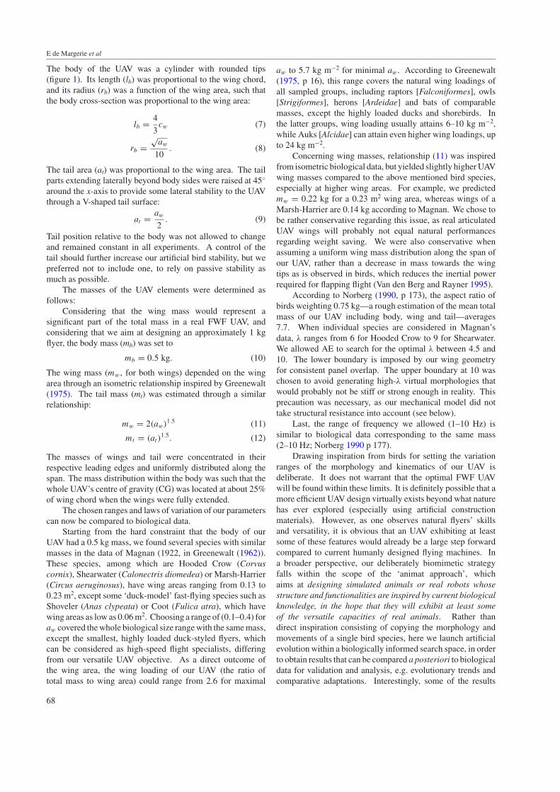
Figure 2. Lift and drag coefficients as computed by the FMFAW model (thin lines), compared to experimental measures on the Selig 4083airfoil (corrected for aspect ratio effect, dotted lines). (a) Outline of the Selig 4083 airfoil. (b) Lift (Cl) and drag (Cd) coefficients of wingsurface elements, as a function of angle of incidence. Although experimental data are only available in the ‘common’ incidence range (−5◦
to 10◦), FMFAW estimates values for the whole 180◦ incidence range. (c) Effects of Reynolds number (Re) and aspect ratio (λ) variations onthe polar lift–drag curve.
obtained in simulation, in a fully controlled environment(contrary to real-world experiments) may, in turn, appearuseful to biologists to disentangle the complex biologicaladaptations such as those involved in FWF.
2.2. Flight simulation
To test the flight characteristics of the multiple FWF solutionsgenerated by the AE algorithm in terms of wing size, shapeand movements, a flight simulator using the air speed vectorat local points of the wing and tail was needed to compute thegenerated aerodynamic forces. This vector was a compositionof both the UAV speed and the speed induced by the wingstroke. Moreover, possibly high local angles of incidence andlateral drift due to sweep had to be accounted for.
We used a model specifically designed for flappingarticulated wings (FMFAW, flight mechanics for flappingarticulated wings), which has been described elsewhere (Druot2004). This semi-empirical, quasi-steady-aerodynamicsmodel considered that a wing was divided in a number ofrigid flat quadrangular wing elements (WEL). In the presentwork, we divided each wing’s IP into three coplanar WELs,and each OP into six coplanar WELs. At each time step(0.005 s in the present work) and for each WEL, the modelestimated the local incident airspeed, and computed threecumulative aerodynamic forces: the leading edge lift, theparachute drag and the friction drag, as described in moredetails by Druot (2004). As the size and shape of our wingscould vary, it was necessary that the model took the aspect ratioand the Reynolds number into account. As a conservativeapproach, the wing aspect ratio (λw) was accounted for byclassical induced lift and drag formulae:
Clλ = Clλw
λw + 2(13)
Cdλ = Cd +Cl2
πλw
(14)
with Clλ, Cdλ being the lift and drag coefficients correctedfor the aspect ratio, and Cl, Cd uncorrected coefficients, i.e.at infinite aspect ratio. λw was common to all WELs, suchthat the whole wing’s aspect ratio affected the performanceof each WEL, whereas the wing movement effects on theeffective aspect ratio were neglected for simplicity. Moreover,no particular loss of aerodynamic efficiency was assumed atthe body/IP and IP/OP interfaces because it was uneasy todetermine a priori what mechanical solution would be adoptedfor the real UAV’s shoulder and wrist, and because we didnot want the optimization process to depend on such mattersinitially.
The Reynolds number (Re) was assumed to have an effecton the friction drag coefficient in FMFAW (Cdf ). Accordingto Norberg (1990), we assumed a dependence on Re0.5 forlaminar flow and on Re0.2 for turbulent flow:
Cdf = max(8 Re−0.5; 0.2 Re−0.2). (15)
Contrary to the aspect ratio, Re (and thus Cdf ) was consideredas a ‘local’ variable, computed at each time step and for eachWEL individually.
As a result of (15), the transition from laminar to turbulentflow happened in our model around Re 2 × 10⁵. As for otherparameters in FMFAW, e.g., those setting the dependence ofthe lift coefficient on the angle of incidence, proportionalitycoefficients in (15) were chosen to have the closest possiblefit with experimental data for a particular airfoil. We chosethe Selig 4083 airfoil, which is an 8% thick, under-camberedairfoil designed for providing high lift and lift/drag ratio at lowReynolds number (6 × 10⁴–2 × 10⁵). Its performances weremeasured experimentally in a wind tunnel for Re 6 × 10⁴–3 ×10⁵ (Selig 1997). Figure 2 compares these experimental curveswith the outcome of FMFAW as used in the present work.Beyond providing useful experimental data to calibrate ourmodel, we chose the Se 4083 for its affinities with wing airfoilsin birds, in terms of shape, thickness, camber, maximum liftcoefficient and Reynolds number range (Withers 1981).
69

E de Margerie et al
Concerning the UAV tail, aerodynamic forces werecalculated similarly to the wings, but assuming a symmetricalNaca 009 airfoil, and a 1.0 value for the aspect ratio. Finally,the body of the UAV was assumed to produce drag only, witha drag coefficient of 0.3 indexed on its frontal area (Norberg1990, p 165).
Although the fit between FMFAW aerodynamic forcesand experimental data at varying Reynolds number seemsrather satisfactory (figure 2), FMFAW remains based onsteady aerodynamics, and thus does not compute unsteadyaerodynamics effects, nor interactions between UAV’s parts.Thus the quantitative results of simulations must be interpretedwith enough caution, especially at low flight speed, whereunsteady effects, interactions and flight in disturbed air growin importance. For this reason, we optimized our UAV usingFMFAW for flight speeds ranging from 6 to 20 m s−1, but notfor lower flight speeds, nor for hovering flight.
Apart from FMFAW and flight mechanics, we used theOpen Dynamics Engine (ODE, Smith 2006) to simulate therelative movements of each part of our articulated UAV andcompute its flight trajectory. Body and wing parts, consideredas not deformable solids, were attached using joints havingthe same DOFs as in figure 1. Sinusoidal angular movementof these four DOFS was obtained by producing enough torqueat the joints to follow precisely the desired kinematic curve asdictated by the UAV’s genome. High torques, possibly up tounrealistic values, were allowed to be produced at some jointsif this was necessary to follow the ‘genetic’ kinematics againstpossibly strong external forces, i.e. weight and aerodynamicforces on wing panels. It was the role of evolution to findan adequate, realistic wing morphology and movement thatminimized the torques at joints, and hence decreased therequired mechanical power, while achieving forward flightat a given speed.
2.3. Evaluation, fitness and evolutionary algorithm
First, we briefly recall the general principles of artificialevolution, and how AE draws inspiration from natural randomvariation and Darwinian selection.
Each potential solution generated by AE is called an‘individual’, as its characters are dictated by a genome(a chain of 12 floating point numbers in the presentwork), and expressed into a phenotype (specific morphologyand kinematics) interacting with a simulated world (flightsimulation). The ‘fitness’ of each individual relative to thechosen problem (forward horizontal flight) is measured duringits lifetime (the duration of an evaluation) and determinesits breeding success, i.e. the chance that its genome will beselected for creating a new individual or ‘offspring’ at the nextevolution step. When an individual possesses a high fitnessand is selected for offspring production, its genome is copied,crossed with the genome of another selected individual,randomly mutated and then expressed into the offspring’sphenotype, which is evaluated in turn.
In the present case, the fitness of each individual wasassessed through a standardized test flight: the UAV waslaunched forward at an initial 300 m height, with a given
initial horizontal speed which was constant for all individualswithin an evolutionary ‘run’ (e.g. 10 m s−1). The geneticallydetermined kinematics of the individual were symmetricallyapplied at joints of both wings since the first time step of theevaluation and for 10 s—i.e. 2000 time steps—during whichthe UAV flew freely: no particular constraint was applied toits trajectory to ‘help’ it achieve a stable horizontal flight. Ateach time step of the evaluation, two variables were recordedin order to quantify the fitness of the individual:
• The distance (D) between the UAV’s body and the ideal‘reference’ trajectory, i.e. a horizontal path at the initiallaunch speed (e.g. 10 m s−1).
• The instantaneous mechanical power (P) produced at thewings’ joints (shoulders and wrists). This variable wascomputed as the sum, for all four joints, of the scalarproduct between the instantaneous torque (τ ) and theinstantaneous rotational speed (ω).
P =4∑
i=1
|�τi .�ωi | (16)
with i referring to each individual joint.
Note that the power was counted positive regardless ofthe sign of the scalar product. This means that the torquesproduced to accelerate the instantaneous joint rotation andthe torques used to slow down the rotation were assumed tohave equivalent energetic costs. We chose this conservativehypothesis which maximized the power consumption, a prioriassuming that the real UAV would probably not have an elasticenergy storage capacity. Referring to assumptions in thebiological literature about the power consumption of birds,some authors consider the acceleration only and ignore thedecelerating power, although some other recommend to addboth, as we did (Van den Berg and Rayner 1995).
At the end of the evaluation flight, the fitness of theindividual was determined by two separate criteria, basedon D and P, respectively: the maximal value attained by Dduring the 10 s—which quantified how far from its referencehorizontal path the UAV’s trajectory diverged, and the meanabsorbed P—which measured the mechanical power cost ofthe achieved flapping movement, given the individual’s sizeand shape:
Fitness = [−max(D); −mean(P )]. (17)
Both fitness parameters were negative, because selectionin the evolutionary algorithm we used favours high fitnessvalues, and because we aimed at reducing both the trajectorydivergence and the power consumption.
The evolutionary algorithm we used (epsilon-MOEA; Debet al 2005) is a multi-objective algorithm that takes intoaccount the two just-mentioned fitness criteria simultaneouslywithout merging them into one single fitness value as manyother algorithms proceed. As an outcome, not a single butseveral individuals are considered as the ‘best’. The selectionscheme is based on the concept of ‘domination’: within thepopulation, the best individuals are those which have fitnessvalues such that no other individual has higher values onboth fitness criteria. The individual is then declared ‘non-dominated’ (see figure 3). By this rule, many individuals in the
70

Artificial evolution of the morphology and kinematics in a flapping-wing mini-UAV
Figure 3. Population and fitness values. Plot of the two fitness criteria (absolute values) for the whole population, at an intermediary step ofevolution (example of a 10 m s−1 run after 10 000 generations). Each cross represents an individual, i.e. the phenotypic performance of agiven genome (a combination of 12 parameter values). The ‘best’ individuals (i.e. ‘non-dominated individuals’ or ‘Pareto front’, see thetext) are those in the bottom left corner (i.e. lower power consumption and lower departure from reference trajectory), represented as whitedots. The next generation will consist of crossing the genome of one individual of the elite (white dot) with one individual of the remainingpopulation (cross). If the offspring is better than both its parents, it will appear closer to the bottom left corner, hence making the Paretofront progress towards better performance.
population can be non-dominated, representing locally optimalcompromises between fitness criteria. These individualsare called ‘Pareto-optimal’ solutions and constitute the mostfavoured individuals for offspring production. In epsilon-MOEA, Pareto-optimal individuals are placed in what is calledan ‘elite’ group, from which one of the two parents implied ineach offspring production is systematically chosen at random.The other parent is chosen among the population (see Debet al (2005) for details). An important particularity of epsilon-MOEA, compared to some other multi-objective algorithms,is that individuals in the elite must differ from each other bysome fitness increment: 0.1 m in trajectory divergence and1.0 W in power consumption, in the present case. In otherwords, the ‘Pareto front’ of the population is interval-sampled.This prevents too much similarity between favoured genitorindividuals within the elite, which often causes the prematureconvergence of evolution towards a local optimum.
The sequence of an evolutionary run was as follows:
1. 2000 individuals with randomly generated genomes werecreated and individually tested.
2. The best individuals, in the sense of the multi-objectivefitness just exposed, were retained to constitute a first elitegroup, and the 100 next individuals, only dominated bythe elite, constituted the root population for evolution.Other individuals were discarded.
3. An individual of the elite was randomly chosen for matingwith another individual drawn from the population.
4. The two genomes were crossed to produce an offspringgenome: each of the 12 parameters in the offspringgenome was randomly chosen from one or the otherparent.
5. The offspring genome was mutated, with a probabilityof 30% for each parameter: the corresponding value wasrandomly increased or decreased by some amount. Thisamount was randomly drawn from a normal distributionof mean 0 and variance 4% of the parameter-authorizedrange.
6. The offspring genome was expressed into a phenotypetested in the flight simulator, and its fitness values weremeasured.
7. If its fitness values made the offspring a non-dominatedindividual compared to individuals currently in thepopulation and the elite, it joined the elite group.Otherwise, it was only placed in the ‘regular’ population,with the condition that it was able to replace a relativelyworse individual. Otherwise, the offspring was discarded.
8. Steps 3–7 were repeated 50 000 times. In the following,we will refer to such a cycle as a generation.
At the end of the evolutionary run, the performance, as well asthe morphological and kinematic parameters, of individuals inthe final elite group was scrutinized.
In order to assess the influence of the flight speed on theevolutionary adaptation of wing size, shape and movement, weconducted separate evolutionary runs with 6, 8, 10, 12, 16 and20 m s−1 initial horizontal speeds. In all runs, only the flightspeed was changed: all individuals had a 500 g body mass,and the same possible range of variation for other parameters.As AE is a stochastic optimization method implying manyrandom draws in initial genome generation, as well as inthe crossover and mutation processes, we felt it necessaryto launch four duplicate runs per flight speed value in orderto estimate how much the resulting adapted morphologiesand kinematics converged (or diverged towards different localoptima). Hence a total of 24 independent evolutionary runswere conducted initially, each one representing 52 000 testflights. As a whole, this represented a total of 3500 virtualflight hours, and approximately 1500 h of computation onstandard personal computers (2 GHz processor with 512 MBof RAM). In a second stage, some supplementary runs werelaunched for further analysis (see section 3).
3. Results and discussion
3.1. Progressive emergence of forward horizontal flight
Figure 4 shows the progression of the Pareto front (‘elite’)of the population through successive generations for one ofthe evolutionary runs aiming at a horizontal flight speedof 10 m s−1. The randomly generated front of the initial
71

E de Margerie et al
Figure 4. Progression of the elite population through 50 000generations. For the same evolutionary run as in figure 3 (10 m s−1
flight), the Pareto front of the population is plotted at 0 (initialrandom individuals), 500, 1000, 10 000, 20 000 and 50 000generations. Within the final elite group (grey dots), onlyindividuals departing less than 2 m from perfect horizontal flight(grey area) are retained for further analysis.
population already contained different compromise solutionsto the horizontal FWF problem. On the right-hand part of thefront were located individuals consuming little or no power, butdeparting significantly from the horizontal trajectory. Theseindividuals consumed no power because they usually did notmove their wings at all, or only through passive movements,i.e. caused by external forces only, and they may be assimilatedto ‘gliders’. As a consequence, they systematically lose heightduring the test flight, as quantified by their score on the distanceto the reference trajectory criterion: 15–20 m departure fromthe horizontal 10 m s−1 trajectory at the end of the 10 s flight.On the left-hand part of the initial front were individuals flyingcloser to a horizontal path (4 m departure), but at the cost ofhigh power consumption, up to 200 W of mechanical powerin that run. Such high power values were usually due tolarge wings, flapping at high frequency and with non-optimalincidence angles. Between these two extreme solutionswere a few other non-dominated individuals with intermediateperformances: better than pure gliders on trajectory departure,and better than the most active flappers on power consumption.After the first 500 generations, the Pareto front progressedsignificantly, meaning that some offspring were better thantheir parents and replaced them in the elite group. This wastrue for all types of solutions: gliders lose less height (12 m)and active flappers consumed less power (120 W). Betterintermediate solutions were also found. Similarly, after 1000offspring generations, the front progressed further, especiallyfor intermediate solutions that became more numerous. Laterin the evolution, after 10 000 generations, the best gliderattained a height loss reduced around 10 m, hence a glide ratioof approximately 10, since the reference trajectory for 10 s at10 m s−1 was a 100 m horizontal path. On the other hand, thedeparture from horizontal trajectory was reduced to 0.6 m, for40 W consumed. During the last 40 000 offspring generations,the evolutionary algorithm processed much slower, with the
generation of individuals decreasing the power consumptionon the ‘active flapper’, left-hand side of the Pareto front(mechanical power finally dropped to 25 W), and little or noprogress on the ‘glider’, right-hand side of the front, attaininglimits of the airfoil’s lift/drag ratio.
Evolutionary runs at other reference flight speeds (6, 8,12, 16 and 20 m s−1) displayed the same trends, thoughwith varying power consumption values. There was anearly emergence of glider solutions, which satisfied only oneof the fitness criteria, and a more progressive evolution ofactive flappers and intermediate solutions towards lower powerconsumption and lower departure from horizontal flight.
At the end of each evolutionary run, after 50 000generations, we retained a few relevant individuals for furtheranalysis of their morphological and kinematic parameters. Wewere only interested in horizontal flight, and not in glideroptimization, despite the fact that evolution possibly usedgliders as parents of active flappers, taking advantage of themulti-objective optimization scheme. Therefore, we tolerateda maximal departure of 2 m from horizontal flight over the10 s flight (see figure 4). Only individuals satisfying thisa posteriori constraint were analysed later in the study.Whether this relative tolerance on trajectory departurerepresents a significant bias on power consumption can beevaluated by considering that, in the worst case, a 2 m heightloss for a 1 kg UAV represents 20 J of lost potential energyduring 10 s, hence a power saving of the order of magnitudeof a few watts, which remains tolerable compared to theoptimized power levels attained at varying flight speeds (seesection 3.2.1). Furthermore, small errors on altitude might alsobe due to the lack of pitch closed-loop control, a situation thatimplies a very accurate parameter tuning that could disappearin a closed-loop control system. All evolutionary runs, atall tested flight speeds, yielded individuals satisfying thisconstraint after 50 000 generations, though in variable number:fewer individuals succeeded in performing a sub-horizontalflight at the lowest (6 m s−1) and highest (20 m s−1) flightspeed, compared to results obtained with intermediate speeds.
3.2. Morpho-kinematic adaptation to varying flight speeds:comparative analysis
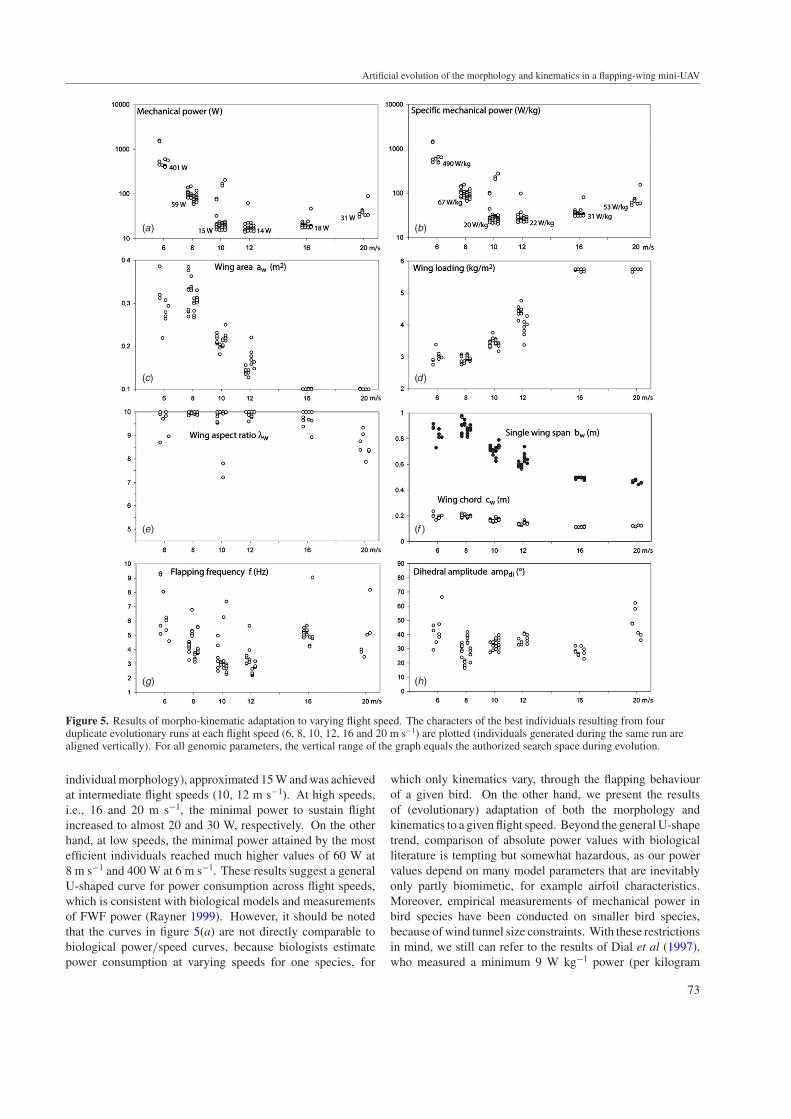
Figures 5 presents the results of the 24 evolutionary runswe launched, i.e. four duplicate runs for six flight speeds.We plotted the performance and parameters of the horizontalactive flappers at the end of evolution. As an outcomeof the stochastic optimization process, variability betweenduplicate runs for the same flight speed existed, by varyingamounts, depending on the variable considered. However,for most variables, there was a significant convergencebetween duplicate runs when compared to differences betweenruns at different flight speeds. In other words, thevariability was low enough to identify and discuss comparativeadaptations.
3.2.1. Power consumption (figures 5(a) and (b)). The lowestmechanical power for horizontal FWF of our 500 g bodiedUAV, plus the mass of wings and tail (which depended on
72
Artificial evolution of the morphology and kinematics in a flapping-wing mini-UAV
(a) (b)
(c) (d)
(e) (f )
(g) (h)
Figure 5. Results of morpho-kinematic adaptation to varying flight speed. The characters of the best individuals resulting from fourduplicate evolutionary runs at each flight speed (6, 8, 10, 12, 16 and 20 m s−1) are plotted (individuals generated during the same run arealigned vertically). For all genomic parameters, the vertical range of the graph equals the authorized search space during evolution.
individual morphology), approximated 15 W and was achievedat intermediate flight speeds (10, 12 m s−1). At high speeds,i.e., 16 and 20 m s−1, the minimal power to sustain flightincreased to almost 20 and 30 W, respectively. On the otherhand, at low speeds, the minimal power attained by the mostefficient individuals reached much higher values of 60 W at8 m s−1 and 400 W at 6 m s−1. These results suggest a generalU-shaped curve for power consumption across flight speeds,which is consistent with biological models and measurementsof FWF power (Rayner 1999). However, it should be notedthat the curves in figure 5(a) are not directly comparable tobiological power/speed curves, because biologists estimatepower consumption at varying speeds for one species, for
which only kinematics vary, through the flapping behaviourof a given bird. On the other hand, we present the resultsof (evolutionary) adaptation of both the morphology andkinematics to a given flight speed. Beyond the general U-shapetrend, comparison of absolute power values with biologicalliterature is tempting but somewhat hazardous, as our powervalues depend on many model parameters that are inevitablyonly partly biomimetic, for example airfoil characteristics.Moreover, empirical measurements of mechanical power inbird species have been conducted on smaller bird species,because of wind tunnel size constraints. With these restrictionsin mind, we still can refer to the results of Dial et al (1997),who measured a minimum 9 W kg−1 power (per kilogram
73
E de Margerie et al
(i ) ( j )
(k) (l )
(m) (n)
(o) (p)
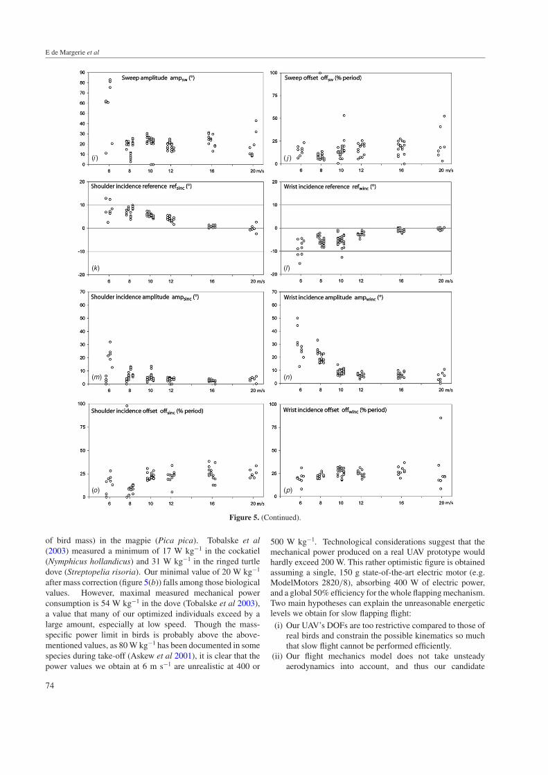
Figure 5. (Continued).
of bird mass) in the magpie (Pica pica). Tobalske et al(2003) measured a minimum of 17 W kg−1 in the cockatiel(Nymphicus hollandicus) and 31 W kg−1 in the ringed turtledove (Streptopelia risoria). Our minimal value of 20 W kg−1
after mass correction (figure 5(b)) falls among those biologicalvalues. However, maximal measured mechanical powerconsumption is 54 W kg−1 in the dove (Tobalske et al 2003),a value that many of our optimized individuals exceed by alarge amount, especially at low speed. Though the mass-specific power limit in birds is probably above the above-mentioned values, as 80 W kg−1 has been documented in somespecies during take-off (Askew et al 2001), it is clear that thepower values we obtain at 6 m s−1 are unrealistic at 400 or
500 W kg−1. Technological considerations suggest that themechanical power produced on a real UAV prototype wouldhardly exceed 200 W. This rather optimistic figure is obtainedassuming a single, 150 g state-of-the-art electric motor (e.g.ModelMotors 2820/8), absorbing 400 W of electric power,and a global 50% efficiency for the whole flapping mechanism.Two main hypotheses can explain the unreasonable energeticlevels we obtain for slow flapping flight:(i) Our UAV’s DOFs are too restrictive compared to those of
real birds and constrain the possible kinematics so muchthat slow flight cannot be performed efficiently.
(ii) Our flight mechanics model does not take unsteadyaerodynamics into account, and thus our candidate
74
Artificial evolution of the morphology and kinematics in a flapping-wing mini-UAV
individuals cannot use effects such as delayed stall toincrease airfoil performance (Vogel 1994).
Since we obtain extreme power values only at low flightspeed, and since unsteady aerodynamics are known to grow inrelative importance at low flight speed, the second hypothesisis theoretically well grounded. As for the first hypothesis, itwill be discussed later during the analysis of morphologicaland kinematic parameters (section 3.2.5).
3.2.2. Wing area (aw) adaptation (figures 5(c) and (d)). Theoptimal wing area emerging from evolution depended greatlyon the flight speed: the general trend was that aw decreasedwith an increasing flight speed. As the mass of the UAV’sbody remained 0.5 kg, the adaptation of wing area impliedan increase of wing loading for higher flight speeds, a well-known relationship for all flying objects, as there is a physicalproportionality relationship between the natural flight speedand the square root of wing loading (e.g. Norberg (1990)). At6–8 m s−1, the mean aw was near 0.3 m2. At 10 and 12 m s−1,aw decreased to approx. 0.2 and 0.15 m2, respectively, i.e., tovalues approaching the natural wing areas of 500 g bodiedbirds such as Marsh-Harrier, Shearwater or Hooded Crow(Greenewalt 1962). At 16 and 20 m s−1, evolution converged tothe minimum allowed wing area value of 0.1 m2, indicating thatselection strongly favoured highly loaded individuals at thesehigh speeds, mimicking a ‘duck-like’ adaptation. It should benoted that optimal individuals at the end of our evolutionaryruns are necessarily ‘specialists’ of the flight speed at whichthey were selected, which is different in natural bird species,whose characters (e.g. wing loading) probably result fromselective compromises over the whole flight speed range theypractice. Whether wing areas values selected here at a givenflight speed would remain functional at other flight speeds, bychanging the wing movement only, is an issue dealt with later(section 3.5).
3.2.3. Wing aspect ratio (λw) adaptation (figures 5(e) and(f )). Evolution yielded high aspect ratio values at almostall tested flight speeds. The maximal ratio value of 10 wasreached by most individuals at 6, 8, 10, 12 and 16 m s−1.It is only at 20 m s−1 that an optimal aspect ratio averaging8.5 was obtained. A λw lower than 7 was never retainedat the end of the evolutionary runs. High aspect ratioshave the beneficial effect of decreasing the induced drag(equation (14)), and hence the forward thrust force thatmust be generated by flapping. However, for a given wingarea, wings with a high aspect ratio have a lower chord andthus experience lower Reynolds number, which increases theairfoil friction drag (equation (15)). Optimal aspect ratioshould theoretically result from a compromise between thesecontradictory effects. The optimal value therefore dependson the flight speed, the wing area and on the sensitivity ofthe airfoil performance to Reynolds number. Moreover, inFWF, the aspect ratio has other implications: more power willbe needed to accelerate/decelerate a high aspect ratio wing,which has higher inertia around the shoulder joint. On theother hand, the flapping frequency would possibly be reduced
with a wing with a high aspect ratio, as wing tip velocityinduced by flapping will be increased by higher wingspans,thus generating higher thrust forces. In the present case, withthe specific characteristics of our UAV in terms of mass, area,airfoil and flight speeds, it appears that the optimal λw is around10 or more, which is above values observed for similarly sizedbirds (7.7 on average; Norberg 1990). This difference has twomain possible origins:
(i) Our simulator did not take structural resistance intoaccount, whereas a bird’s fitness strongly depends onmaintaining the integrity of its wing structure with areasonable safety factor. In other words, depending on thematerial used, it is possible that high aspect ratio wingswould bend or break during flapping at a high frequency.This is a first selective pressure towards low aspect ratiowings that is lacking in our study.
(ii) Most importantly, we only selected our UAVs forforward flight. Thus no selective pressure wasplaced on manoeuvrability, on flight in obstructed areas(vegetation), or simply on wing folding for walks on theground, which are factors that all favour the selectionof lower aspect ratios in birds, at the expense of aslightly lower aerodynamic efficiency (Norberg 1990,2002). Considering these limitations compared to naturalconditions, it is not surprising that simulated evolutionconverged towards what can be considered as high aspectratio ‘open space flyers’, somewhat analogous to marinebird species that are almost 100% occupied in flying, suchas albatrosses and other Diomedeidae or Procellaridae.
3.2.4. Flapping frequency (f ) and Dihedral amplitude (ampdi)adaptation (figures 5(g) and (h)). At intermediate speeds(10 and 12 m s−1), the flapping stroke frequency was about3 Hz. This value is in the lower biological range (2–10 Hzat this mass, Norberg 1990), which is not surprising given thelong, seabird-like wings of our UAV: with this morphology,sufficient thrust can be generated with a low flapping frequency(Norberg, 1990, p 177). As a point of comparison, the Kelpgull (Larus dominicanus) has a ‘natural’ flapping frequencyof 3.5 Hz (Pennycuick 1996), for mass and area (0.89 kgand 0.23 m2) characteristics comparable to those of ourintermediate speed UAV. However, this species has a slightlylower aspect ratio of approximately 7.5.
Slow and fast flight both implied higher frequency values(closer to 5 Hz on average), which contribute to explain theobserved increase in power consumption at those speeds.Concerning the stroke amplitude, there was a less clearadaptive trend, with most individuals presenting a dihedralamplitude in the 25◦–45◦ range, with some increase at thelowest and highest flight speeds, contributing further to theincrease in mechanical power. As a whole, it seems thatvariations in both the stroke frequency and amplitude wereimplied in the adaptation of flapping kinematics to flightspeed. However, the two variables did not vary similarly:for example, only frequency increased from 12 to 16 m s−1
(with a slight decrease in stroke amplitude), whereas onlyamplitude increased from 16 to 20 m s−1, suggesting that thesevariables exhibit a rather complex adaptive landscape. These
75

E de Margerie et al
trends are unfortunately not easily comparable to intraspecificbiological kinematic data because, in the present case, the wingarea varied between flight speeds. Nevertheless, it should bementioned that biological data show that flapping frequencydepends on the flight speed in some species, while it remainsfairly constant in others (Tobalske and Dial 1996, Park et al2001).
3.2.5. Sweep amplitude (ampsw) and offset (offsw) adaptation(figures 5(i) and (j)). The potential usefulness—orworthlessness—of an articulated wing in a FWF UAV isan interesting issue that has not been directly addressedpreviously. Of course birds and bats have elbow and wrist anduse these DOFs in flight, with the amount depending on speciesand flight speed (Tobalske and Dial 1996, Park et al 2001,Tobalske et al 2003). From an adaptationist, functionalistpoint of view, this suggests that an articulated wing may beaerodynamically useful. On the other hand, other factorsconstrain the presence of wing articulations in birds and bats:first of all, the heredity of a vertebrate limb organization planis a historical, contingent constraint that questions the purelyfunctional necessity of an articulated wing. For example,insect can fly efficiently without articulated wings. Moreover,an articulated wing may be beneficial to other functionalaspects than forward flight, e.g., to increased manoeuvrability,and the simple biological necessity to fold wings on the groundrepresents a potentially strong natural selective pressure that isnot necessarily relevant for an UAV. Hence it was interestingto test whether the presence of a wrist in our simulated wingwas used by evolution for purely forward flight and to quantifyits possible beneficial effects.
Figure 5(i) shows that the sweep of the outer panel wasused by almost all optimized individuals, at all flight speeds.Between 8 and 20 m s−1, the amplitude of the sweep didnot vary much in a consistent manner and averaged 25◦. Adifferent pattern appeared at 6 m s−1, as most individuals at thislowest speed used a much higher amount of sweep, attaining60◦–80◦. Figure 5(j) shows how the sweep was synchronizedwith the dihedral: the sweep (SW) tended to have a 0–25%period offset compared to the dihedral (DI) which, accordingto equations (1) and (2), shows that a maximal sweep angle(i.e. adducted wing tips, minimal wingspan) was attained inthe second half of the upstroke, whereas a zero sweep angle(i.e. fully extended wing) was attained in the second half ofthe downstroke. This is close to what is observed in birds, forwhich it has been usually reported that the maximal wingspanoccurs at mid-downstroke, and minimal wingspan at mid-upstroke, which corresponds to a 25% value for offsw. Theamount of wing retraction was globally less than in real birds:given our UAV morphology (figure 1), the ratio of minimalto maximal wingspan was 0.95 for 25◦ of sweep, 0.75 for60◦ and 0.58 for 80◦. Birds for which this same ‘span ratio’variable has been measured in flight exhibit much lower values,usually below 0.5 (Tobalske and Dial 1996, Park et al 2001,Tobalske et al 2003). Moreover, most of these species (e.g.Barn Swallow [Hirundo rustica], Pigeon [Columba livia],Cockatiel [Nymphicus hollandicus]) have a tendency to retracttheir wings more at a higher speed, which is not observed in
the present case. As already noted, this discrepancy can partlyresult from the fact that our UAV’s size changed between flightspeeds, hence the wing area adaptation need not be achievedthrough partial wing folding as in real birds. It is also importantto note that the bird species thus investigated are far from the‘seabird’ morphotype, for which data on the span ratio arelacking. We speculate from personal observations that wingadduction in gulls and akin species is less pronounced than inpigeons for example. There are also structural reasons whyour UAV retracts its wings rather modestly compared to birds.First, the wrist in our UAV cannot be adducted, as only thewingtips can. This constraint de facto limits the span ratio to aminimal value of 0.5. Second, as wrists cannot move forwardor backward relative to the body, we considered the possibilitythat a strong sweep of the external panel would separate thelift centre of the wing from the centre of gravity of the UAV,and hence cause pitch torques and instability issues. However,this hypothesis is partly refuted by the fact that individuals at6 m s−1 succeed in using up to 83◦ of sweep. It remains that thelimitations we put on wing retraction, suggested by anticipatedconstraints on prototype construction, might indeed partlycause the very high power consumptions we obtained at lowspeed. This could indeed prevent our UAV from exploringsome of the wing movements a bird can achieve, which areespecially refined at low speeds, as illustrated and discussed inthe biological literature mentioned herein. Although the wingretraction possibilities of our UAV were modest compared tothose of birds and bats, it remains that the wrist sweep wasalmost systematically used, thus suggesting that it allowedthe generation of more efficient aerodynamic forces. To testthis idea further, we quantified the power gained from wristmovements (see section 3.4).
3.2.6. Shoulder and wrist incidence rotations (figures 5(k)–(p)). The shoulder incidence position (SINC) determinesthe angle between IP and body, whereas the wrist incidenceposition (WINC) determines the angle between OP and IP.Hence, the angle between OP and body results from the sumof SINC and WINC. Plots of reference angles versus flightspeed (refsinc, refwinc, figures 5(k) and (l)) show that IP tendedto have a higher angle of incidence at low speed, but not OP:negative angles at the wrist tended to compensate the positiveangles at the shoulder. Concerning the variation of the angleof incidence, its amplitude (ampsinc, ampwinc, figures 5(m) and(n)) tended to increase with lower flight speeds, for both IPand OP, which is in agreement with kinematic data in birdswhich associate higher variations in the wing angle of attackwith slow flights (Hedrick et al 2002). It is noteworthy thatSINC and WINC values, being relative angles between bodyand wing panels, provide only indirect information on theaerodynamic angle of attack, which depends on the incident airspeed induced by the flapping stroke, and on possible changesin the body tilt angle (see section 3.2.7). The offset between theincidence and dihedral oscillation (offsinc, offwinc, figures 5(o)and (p)) converged to values approaching 25% on average.In other words, a maximal positive incidence was attainedat mid-upstroke, while a minimal incidence (often negative
76

Artificial evolution of the morphology and kinematics in a flapping-wing mini-UAV
Table 1. Parameters of the most power-saving individual at each flight speed.
Flight speed (m s−1)
6 8 10 12 16 20
FitnessMean P (W) 401 59 15 14 18 31Max D (m) 1.11 1.95 1.98 1.77 1.80 1.48
Genomeaw (m2) 0.264 0.299 0.225 0.145 0.100 0.100λw 10.0 10.0 10.0 10.0 9.6 8.4f (Hz) 6.25 3.30 2.41 3.03 4.83 4.01ampdi (◦) 40.3 34.0 32.8 32.7 27.9 47.7ampsw (◦) 75.4 10.8 25.0 20.0 30.2 16.6offsw (%) 17.0 11.2 14.6 13.5 25.1 9.7refsinc (◦) 6.4 4.8 4.8 4.6 1.4 −0.7ampsinc (◦) 18.8 11.1 4.3 3.2 3.1 3.9offsinc (%) 21.1 7.8 20.0 24.1 32.6 20.6refwinc (◦) −11.3 −5.4 −3.3 −2.8 −0.9 0.0ampwinc (◦) 24.2 16.3 7.3 7.1 6.2 6.7offwinc (%) 22.3 25.6 27.2 24.5 23.7 33.9
Other informationbw (m) 0.81 0.87 0.75 0.60 0.49 0.46cw (m) 0.18 0.19 0.17 0.13 0.11 0.12rb (m) 0.05 0.05 0.05 0.04 0.03 0.03Total span (m) 1.68 1.78 1.55 1.24 1.01 0.95mb (kg) 0.500 0.500 0.500 0.500 0.500 0.500mw (kg) 0.272 0.327 0.213 0.110 0.063 0.063mt (kg) 0.048 0.058 0.038 0.020 0.011 0.011Total mass (kg) 0.820 0.885 0.751 0.630 0.574 0.574Wing loading (kg m−2) 3.1 3.0 3.3 4.3 5.7 5.7Specific power (W kg−1) 490 67 20 22 31 53
angles between body and wing panels) was attained at mid-downstroke. As a direct outcome, this pattern tends to maintainthe wing airfoil at low angles of attack throughout the stroke,thus maximizing the lift/drag ratio (figure 2).
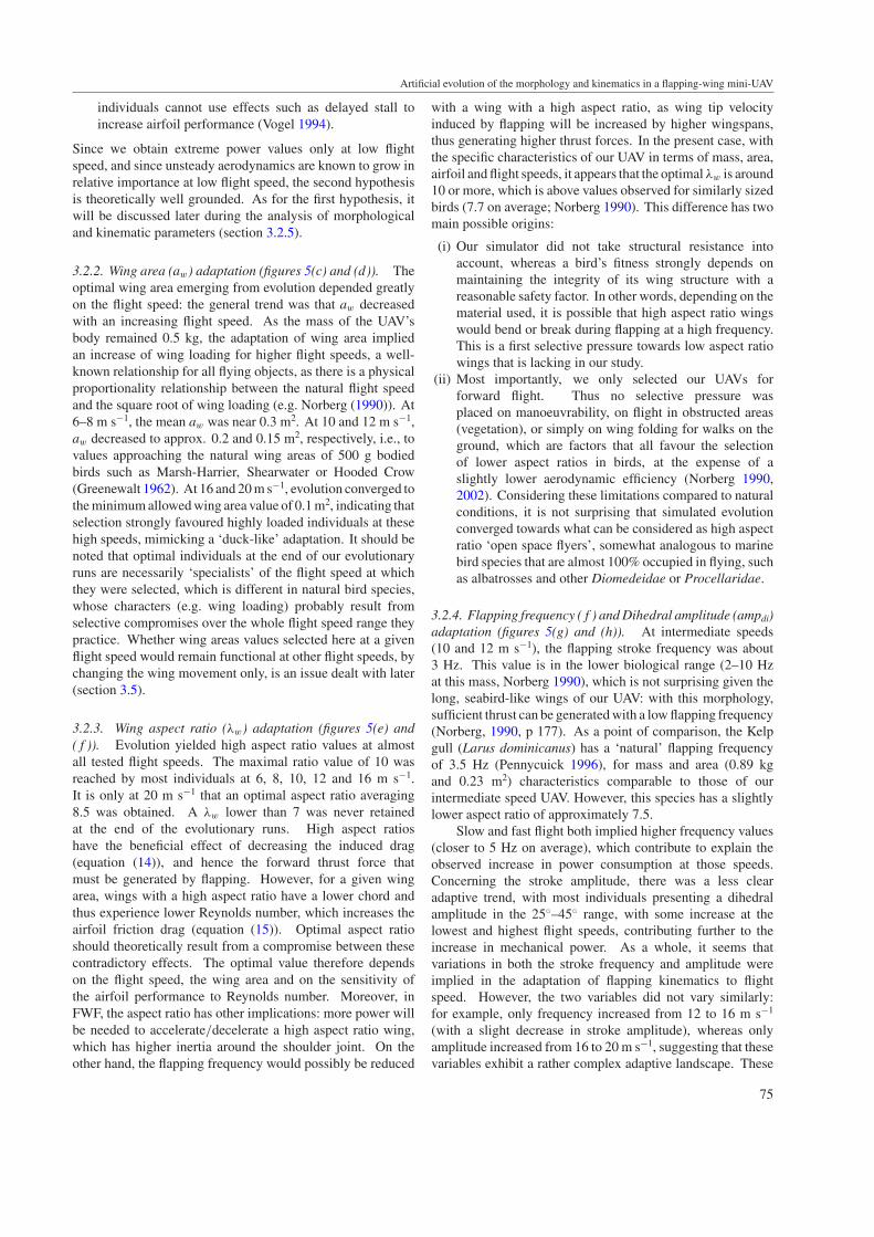
3.2.7. Analysis of aerodynamic forces in representativeindividuals. To investigate the respective aerodynamicrole of inner/outer panels during downstroke and upstrokethroughout the flight speed range, we plotted the aerodynamicforces generated by IP and OP along the flight path for oneindividual. We chose the most power-saving individual ateach flight speed. As a consequence of the dual-objectiveoptimization scheme, these individuals do not necessarily havethe best performances in terms of horizontality of flight. Incontrast, it turns out that the best individuals in terms of flighthorizontality achieved their flight at the expense of powerconsumptions that were an order of magnitude higher, withmuch more variability between duplicate runs, than thoseof the six individuals selected here—clearly suggesting thatthey were much less aerodynamically efficient, and hence lessinteresting and representative of aerodynamic optimization.As a complementary illustration, we also produced in-flight motion videos of these six individuals (available onhttp://animatlab.lip6.fr). Numerical values of all parametersfor these individuals are presented in table 1.
A first remark concerns the trajectory and positionof the body. It followed an oscillating path, ascendingduring downstroke and descending during downstroke. More
interestingly, the body axis took a significantly tilted position atlow speed (up to approx. 30◦ at 6 m s−1), a tendency observedand measured with comparable amounts in birds (Tobalskeand Dial 1996, Tobalske et al 2003).
Considering the forces generated by OP, it appeared thatthe force generation was almost fully concentrated during thedownstroke, regardless of the flight speed. These downstrokeOP forces had both vertical (upward) and horizontal (forward)components, showing that OP had both a lifting and apropulsive function. At the beginning of the upstroke,weak lifting forces were also produced, but shifted to weakdownward forces later in the upstroke. As a whole, OPwas almost inactive during the upstroke at all flight speeds.Interestingly, at 6 m s−1, this asymmetric OP force patternbetween downstroke and upstroke was achieved through adrastic variation in the relative air speed: the simultaneouseffects of a high wrist sweep—causing backward retractionof the outer wing part during upstroke—and the body tiltangle produced an almost zero OP horizontal speed duringupstroke, while the same panel was greatly accelerated duringdownstroke. At higher flight speed, such a velocity differencewas not observed with comparable amounts, thus suggestingthat the absence of OP upstroke forces was mainly caused byplacing the OP airfoil at a non-lifting angle of attack.
Concerning IP, the force generation exhibited a differentpattern. Forces were more evenly distributed among down-and upstroke, and included a lift (upward) and a drag(backward) component. This showed that IP, contrary to OP,
77
E de Margerie et al
Figure 6. Aerodynamic forces on the wing panels of six optimized UAVs. The force vectors are summed over the ‘wing elements’ (WELs,see section 2.2) constituting a single (inner or outer) panel. The vectors’ origins are on a line representing the trajectory of each panel’scentre of area. Tail and fuselage forces are not represented for clarity. The flight direction is from left to right.
did not usually participate in the propulsion of the UAV. ThisIP force pattern changed somewhat at the highest speeds, witha weakening of upstroke forces, with relatively stronger forcesgenerated during the downstroke and with a slight forwardcomponent of the generated force at mid-downstroke. As awhole, this IP force pattern at high speed was closer to thepreviously described OP force pattern.
The comparison of the mean force amplitude over the fullstroke on OP and IP showed a clear OP domination at 6 m s−1,and a more even repartition over the wingspan at other speeds.This is explained by the fact that the airflow is dominated bywing flapping at slow flight speeds (Hedrick et al 2002), andhence depends on the distance from the articulated dihedraljoint.
Concerning the down-/upstroke repartition for the wingas a whole, more lifting forces and all propulsive forces weregenerated at the downstroke, at all flight speeds. This wasmainly due to OP generating forces during downstroke only.However, according to what has been described above, thisdownstroke domination tend to be less obvious at intermediatespeeds (8–12 m s−1) as lift produced by IP during upstroke tookrelatively higher importance. This is globally convergent withthe results of Hedrick et al (2002) in the Dove and Cockatiel:these birds appear to have a more continuous lift generation atintermediate speeds (Hedrick et al 2002, Tobalske et al 2003).These significant variations in force generation modes acrossthe flight speed range suggest that the limited kinematics ofour UAV compared to real birds, which prevent very adductedupstrokes (e.g. ‘feathered’ upstroke, Tobalske and Dial 1996),
still leave room for efficient adaptation in the aerodynamicflight regime.
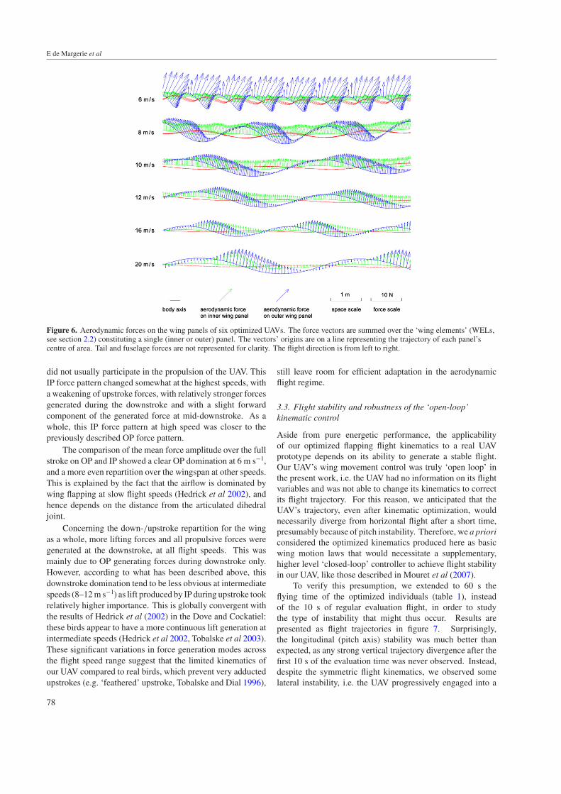
3.3. Flight stability and robustness of the ‘open-loop’kinematic control
Aside from pure energetic performance, the applicabilityof our optimized flapping flight kinematics to a real UAVprototype depends on its ability to generate a stable flight.Our UAV’s wing movement control was truly ‘open loop’ inthe present work, i.e. the UAV had no information on its flightvariables and was not able to change its kinematics to correctits flight trajectory. For this reason, we anticipated that theUAV’s trajectory, even after kinematic optimization, wouldnecessarily diverge from horizontal flight after a short time,presumably because of pitch instability. Therefore, we a prioriconsidered the optimized kinematics produced here as basicwing motion laws that would necessitate a supplementary,higher level ‘closed-loop’ controller to achieve flight stabilityin our UAV, like those described in Mouret et al (2007).
To verify this presumption, we extended to 60 s theflying time of the optimized individuals (table 1), insteadof the 10 s of regular evaluation flight, in order to studythe type of instability that might thus occur. Results arepresented as flight trajectories in figure 7. Surprisingly,the longitudinal (pitch axis) stability was much better thanexpected, as any strong vertical trajectory divergence after thefirst 10 s of the evaluation time was never observed. Instead,despite the symmetric flight kinematics, we observed somelateral instability, i.e. the UAV progressively engaged into a
78
Artificial evolution of the morphology and kinematics in a flapping-wing mini-UAV
Figure 7. Flight trajectories (side views) of optimized UAVs during extended 60 s flights. Thick lines represent the 10 s initial evaluationflight. Thin lines represent the 50 s flight prolongation and demonstrate good longitudinal stability, but lesser lateral stability at low speed(spiral dive) of open-looped controlled FWF UAVs (see the text). (∗) Trajectory of the individual optimized for 20 m s−1, launched at alower speed (6 m s−1): horizontal flight at 20 m s−1 is recovered. (∗∗) Trajectory of the individual optimized for 6 m s−1, launched at ahigher speed (20 m s−1): horizontal flight is not achieved, due to lateral instability.
descending spiral turn. This spiral occurred after a longer timeat high flight speed, individuals flying at 16 and 20 m s−1 beingable to fly for 60 s without being affected. Even during theserelatively longer forward flights, pitch stability was observedthroughout, the sub-horizontal trajectory being maintained forthe whole minute (i.e. 920 and 1200 m distances, respectively).Moreover, a few supplementary flight tests, with variableinitial speeds on the same individual, demonstrated that someindividuals were able to passively correct large discrepanciesin flight speeds. For example, the individual optimized for20 m s−1 and launched at 6 m s−1 was able to return toits horizontal 20 m s−1 flight within a minute (figure 7).Unfortunately, the opposite test of launching the individualoptimized for 6 m s−1 at 20 m s−1 was unsuccessful, as lateralinstability soon occurred (figure 7).
It is probable that our initial choice of placing theCG at 25% of wing chord, where lift forces apply, andof providing the morphology with a large tail helped theUAV to achieve pitch stability, at least in gliding flight.However, the fact remains that most non-optimized flappingkinematics during evolutionary exploration had as a firstconsequence to destabilize the UAV and to place it onan erratic flight trajectory. In this perspective, it is aninteresting result that optimized UAVs were finally able toachieve a reasonable amount of passive pitch stability in flight.This suggests that the necessarily superimposed closed-loopcontroller mentioned above will eventually have relativelylittle corrective work to do to provide long-term longitudinal—and lateral—stability.
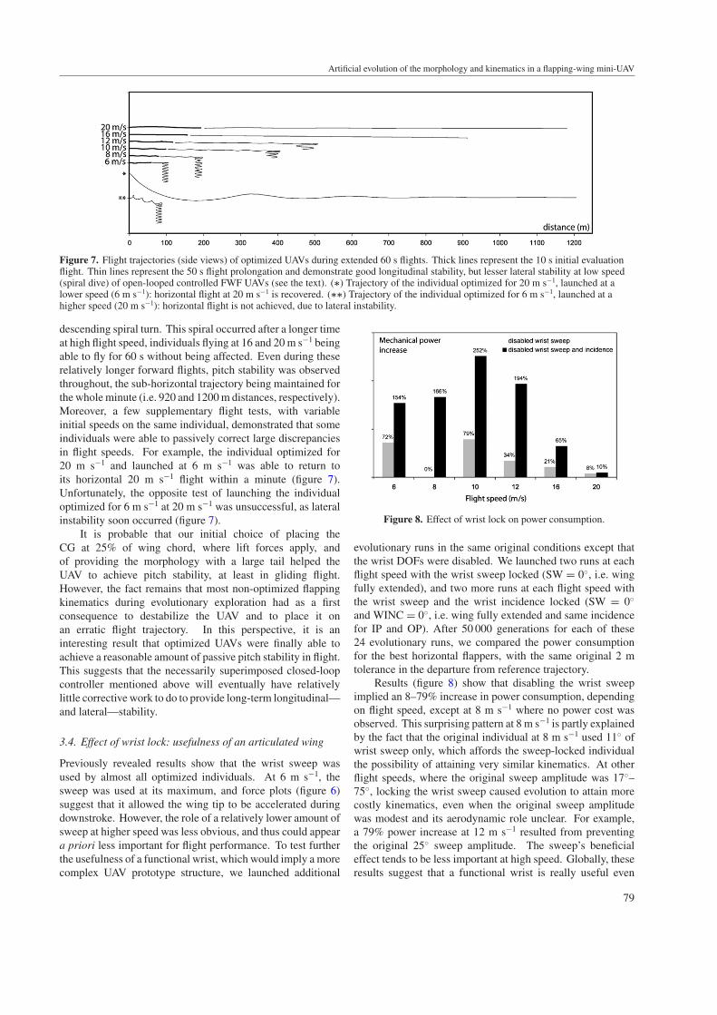
3.4. Effect of wrist lock: usefulness of an articulated wing
Previously revealed results show that the wrist sweep wasused by almost all optimized individuals. At 6 m s−1, thesweep was used at its maximum, and force plots (figure 6)suggest that it allowed the wing tip to be accelerated duringdownstroke. However, the role of a relatively lower amount ofsweep at higher speed was less obvious, and thus could appeara priori less important for flight performance. To test furtherthe usefulness of a functional wrist, which would imply a morecomplex UAV prototype structure, we launched additional
Figure 8. Effect of wrist lock on power consumption.
evolutionary runs in the same original conditions except thatthe wrist DOFs were disabled. We launched two runs at eachflight speed with the wrist sweep locked (SW = 0◦, i.e. wingfully extended), and two more runs at each flight speed withthe wrist sweep and the wrist incidence locked (SW = 0◦
and WINC = 0◦, i.e. wing fully extended and same incidencefor IP and OP). After 50 000 generations for each of these24 evolutionary runs, we compared the power consumptionfor the best horizontal flappers, with the same original 2 mtolerance in the departure from reference trajectory.
Results (figure 8) show that disabling the wrist sweepimplied an 8–79% increase in power consumption, dependingon flight speed, except at 8 m s−1 where no power cost wasobserved. This surprising pattern at 8 m s−1 is partly explainedby the fact that the original individual at 8 m s−1 used 11◦ ofwrist sweep only, which affords the sweep-locked individualthe possibility of attaining very similar kinematics. At otherflight speeds, where the original sweep amplitude was 17◦–75◦, locking the wrist sweep caused evolution to attain morecostly kinematics, even when the original sweep amplitudewas modest and its aerodynamic role unclear. For example,a 79% power increase at 12 m s−1 resulted from preventingthe original 25◦ sweep amplitude. The sweep’s beneficialeffect tends to be less important at high speed. Globally, theseresults suggest that a functional wrist is really useful even
79
E de Margerie et al
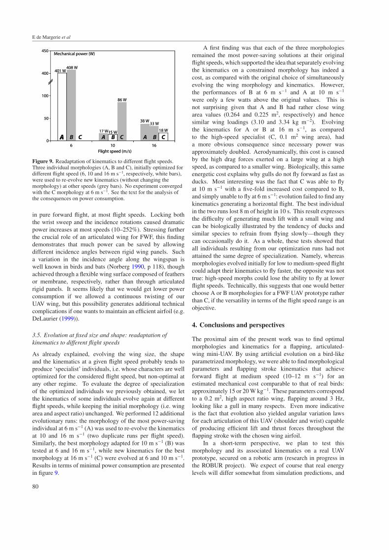
Figure 9. Readaptation of kinematics to different flight speeds.Three individual morphologies (A, B and C), initially optimized fordifferent flight speed (6, 10 and 16 m s−1, respectively, white bars),were used to re-evolve new kinematics (without changing themorphology) at other speeds (grey bars). No experiment convergedwith the C morphology at 6 m s−1. See the text for the analysis ofthe consequences on power consumption.
in pure forward flight, at most flight speeds. Locking boththe wrist sweep and the incidence rotations caused dramaticpower increases at most speeds (10–252%). Stressing furtherthe crucial role of an articulated wing for FWF, this findingdemonstrates that much power can be saved by allowingdifferent incidence angles between rigid wing panels. Sucha variation in the incidence angle along the wingspan iswell known in birds and bats (Norberg 1990, p 118), thoughachieved through a flexible wing surface composed of feathersor membrane, respectively, rather than through articulatedrigid panels. It seems likely that we would get lower powerconsumption if we allowed a continuous twisting of ourUAV wing, but this possibility generates additional technicalcomplications if one wants to maintain an efficient airfoil (e.g.DeLaurier (1999)).
3.5. Evolution at fixed size and shape: readaptation ofkinematics to different flight speeds
As already explained, evolving the wing size, the shapeand the kinematics at a given flight speed probably tends toproduce ‘specialist’ individuals, i.e. whose characters are welloptimized for the considered flight speed, but non-optimal atany other regime. To evaluate the degree of specializationof the optimized individuals we previously obtained, we letthe kinematics of some individuals evolve again at differentflight speeds, while keeping the initial morphology (i.e. wingarea and aspect ratio) unchanged. We performed 12 additionalevolutionary runs: the morphology of the most power-savingindividual at 6 m s−1 (A) was used to re-evolve the kinematicsat 10 and 16 m s−1 (two duplicate runs per flight speed).Similarly, the best morphology adapted for 10 m s−1 (B) wastested at 6 and 16 m s−1, while new kinematics for the bestmorphology at 16 m s−1 (C) were evolved at 6 and 10 m s−1.Results in terms of minimal power consumption are presentedin figure 9.
A first finding was that each of the three morphologiesremained the most power-saving solutions at their originalflight speeds, which supported the idea that separately evolvingthe kinematics on a constrained morphology has indeed acost, as compared with the original choice of simultaneouslyevolving the wing morphology and kinematics. However,the performances of B at 6 m s−1 and A at 10 m s−1
were only a few watts above the original values. This isnot surprising given that A and B had rather close wingarea values (0.264 and 0.225 m2, respectively) and hencesimilar wing loadings (3.10 and 3.34 kg m−2). Evolvingthe kinematics for A or B at 16 m s−1, as comparedto the high-speed specialist (C, 0.1 m2 wing area), hada more obvious consequence since necessary power wasapproximately doubled. Aerodynamically, this cost is causedby the high drag forces exerted on a large wing at a highspeed, as compared to a smaller wing. Biologically, this sameenergetic cost explains why gulls do not fly forward as fast asducks. Most interesting was the fact that C was able to flyat 10 m s−1 with a five-fold increased cost compared to B,and simply unable to fly at 6 m s−1: evolution failed to find anykinematics generating a horizontal flight. The best individualin the two runs lost 8 m of height in 10 s. This result expressesthe difficulty of generating much lift with a small wing andcan be biologically illustrated by the tendency of ducks andsimilar species to refrain from flying slowly—though theycan occasionally do it. As a whole, these tests showed thatall individuals resulting from our optimization runs had notattained the same degree of specialization. Namely, whereasmorphologies evolved initially for low to medium-speed flightcould adapt their kinematics to fly faster, the opposite was nottrue: high-speed morphs could lose the ability to fly at lowerflight speeds. Technically, this suggests that one would betterchoose A or B morphologies for a FWF UAV prototype ratherthan C, if the versatility in terms of the flight speed range is anobjective.
4. Conclusions and perspectives
The proximal aim of the present work was to find optimalmorphologies and kinematics for a flapping, articulated-wing mini-UAV. By using artificial evolution on a bird-likeparametrized morphology, we were able to find morphologicalparameters and flapping stroke kinematics that achieveforward flight at medium speed (10–12 m s−1) for anestimated mechanical cost comparable to that of real birds:approximately 15 or 20 W kg−1. These parameters correspondto a 0.2 m2, high aspect ratio wing, flapping around 3 Hz,looking like a gull in many respects. Even more indicativeis the fact that evolution also yielded angular variation lawsfor each articulation of this UAV (shoulder and wrist) capableof producing efficient lift and thrust forces throughout theflapping stroke with the chosen wing airfoil.
In a short-term perspective, we plan to test thismorphology and its associated kinematics on a real UAVprototype, secured on a robotic arm (research in progress inthe ROBUR project). We expect of course that real energylevels will differ somewhat from simulation predictions, and
80
Artificial evolution of the morphology and kinematics in a flapping-wing mini-UAV
that some fine-tuning of kinematics will be necessary to correctfor the inescapable simulation approximations.
Beyond medium-speed steady flight, the main interestin flapping-wing flight for an UAV is the potential to varyits flight speed by a large amount and to achieve specialflight modes such as hovering or gliding. Though we couldnot cover the whole flight domain extensively in the presentstudy, we already gained valuable information on the energeticconsequences of speed variation. Flying at high speed(16–20 m s−1) could be achieved at rather low cost (20–30 W)in a small UAV (0.1 m2), but with a loss of flight abilitiesat lower speeds. On the other hand, we observed that itwas possible to readapt the kinematics of a larger UAV (0.2–0.3 m2), initially optimized for lower speed flight, to fly athigh speed for a reasonable power cost (30–40 W at 16 m s−1).This second strategy hence seems more promising in theperspective of a versatile real UAV.
Flying at low speed (6–8 m s−1) appeared very costly,and unrealistic power consumption was attained at 6 m s−1.Though the steady aerodynamics that were used in oursimulation probably underestimated the lift production in slowflight, it is possible that our articulated morphology, as itstands, is inadequate for very slow or hovering flights, at leastfor a 1 kg UAV prototype. Even birds of this size hardlyachieve hovering for more than a few seconds. At the otherend of the flight domain, the fact that our UAV was ableto achieve gliding flight with a decent sinking speed (around−1 m s−1) is encouraging and suggests that biomimetic energy-saving behaviours, through soaring in ascending air, are withinreach of our UAV’s abilities.
Another original result brought by this work concernsthe usefulness of an articulated wing for flapping flight: evenwithout considering turning or manoeuvrability issues, wealready learned that the movement of the wrist may have astrong influence on energy saving in forward flight, especiallyat medium-speed flight: compared to monolithic wings,allowing sweep and incidence rotations of no more than 20◦–25◦ at mid-span can drastically reduce the power consumptionof a FWF UAV, provided that these supplementary movementsare well synchronized with the flapping stroke. In other words,this finding suggests that implementing an articulated wingon an UAV prototype might be worth the implied technicalcomplications.
Finally, from a methodological point of view, we mainlyrelied on biological data to validate/analyse our results. Thiswas facilitated by the fact that we initially constrained theevolutionary search space to biomimetic morphologies andkinematics, in agreement with the rationale of the animatapproach. Although more efficient flapping-wing machinesmay exist outside these boundaries, we are convincedthat discovering and analysing such non-biomimetic FWFsolutions would probably have been much more difficult, aswe could not have relied on zoological records as a helpfuldocumented reference for a preliminary validation of ourresults before experiments on real prototypes. Conversely,some of our simulation results should be useful to biologists.Although being not as reliable as real-world measures,artificial evolution coupled with environment simulation may
be considered as a very valuable, fully controlled experimentalframework serving to test the effect of all sorts of constraints—physical, historical or developmental—-on the course andoutcome of adaptation of all sorts of biological characters.Such an evolutionary modelling approach should be especiallyuseful for functional morphologists and biomechanicists (deMargerie et al 2006). As illustrated by the present work onFWF, many experiments that would be impossible in a windtunnel may be relatively easily reproduced in simulation andyield original results, such as the following:
• Flapping-wing flight without the brain. Ourflight experiments with purely open-looped kinematicsdemonstrate that flapping a wing efficiently doesnot necessarily compromise the passive gliding-flightstability, nor does a short forward flight necessarilyrequire any stabilizing neural control. This kind of result,possibly reinforced by experiments on variable tail areasfor example, could provide useful information on thedegree of active stabilization the extant birds need toachieve in flight, and also produce valuable argumentson the morphological and neurological prerequisites forthe emergence of flight in vertebrates.
• Flapping-wing flight with a stiff wing. We were ableto independently lock some degrees of freedom in ourmorphology, which is hardly conceivable on a real birdin a wind tunnel, and to evaluate the consequences onthe energetic cost of flapping flight after letting the UAVreadapt its kinematics. It was thus demonstrated that evena limited sweep movement of the outer wing part cansave a significant part of power consumption and that theability to vary the incidence angle along the wingspan isa crucial feature of FWF at this size.
We are convinced that, as well as roboticists drawing helpfulinspiration from zoological records and Darwinian evolution(Meyer and Guillot 2007), biologists interested in adaptationat a high integration level, such as organismal biologists orecologists, can find new lines of evidence by using artificialevolution on modelled organisms. Although the structure ofour study—notably the type of artificial evolution experimentsthat were conducted and the way the results were analysed—was primarily aimed at helping to design an UAV, and not atyielding biologically relevant findings, we hope the presentwork still participates in demonstrating these reciprocatinginterests.
Acknowledgment
The authors thank T Druot for helpful advice on using andimproving the FMFAW flight simulator. The authors aregrateful towards the anonymous referee whose commentshelped in improving our manuscript. This study was partlyfunded by a post-doctoral fellowship of the French ‘DirectionGenerale de l’Armement’ (DGA) for E de Margerie.
References
Angeli A, Filliat D, Doncieux S and Meyer J-A 2006 2Dsimultaneous localization and mapping for micro aerialvehicles Proc. Eur. Micro Aerial Vehicles (EMAV 2006) Conf.
81

E de Margerie et al
Askew G N, Marsh R L and Ellington C P 2001 The mechanicalpower output of the flight muscles of blue-breasted quail(Coturnix chinensis) during take-off J. Exp. Biol. 2043601–19
Barate R, Doncieux S and Meyer J-A 2006 Design of a bio-inspiredcontroller for dynamic soaring in a simulated UAV Bioinsp.Biomim. 1 76–88
de Margerie E, Tafforeau P and Rakotomanana L 2006 In silicoevolution of functional morphology: a test on bone tissuebiomechanics J. R. Soc. Interface 3 679–87
Deb K, Mohan M and Mishra S 2005 Evaluating theepsilon-domination based multi-objective evolutionaryalgorithm for a quick computation of Pareto-optimal solutionsEvol. Comput. 13 501–25
DeLaurier J 1999 The development and testing of a full-scalepiloted ornithopter Can. Aeronaut. Space J. 45 72–82
Dial K P, Biewener A A, Tobalske B W and Warrick D R 1997Mechanical power output of bird flight Nature390 67–70
Doncieux S, Mouret J, Muratet L and Meyer J-A 2004 The ROBURproject: towards an autonomous flapping-wing animat Proc.Journees MicroDrones (Toulouse)
Druot T 2004 Technical report on the implementation and validationof a flight mechanics simulator for flapping articulated wingsAvailable at http://animatlab.lip6.fr
Ellington C P 1984 The aerodynamics of hovering insect flight: IV.Aerodynamic mechanisms Phil. Trans. R. Soc. Lond. B305 79–113
Ellington C P, van den Berg C, Willmott A P and Thomas A L R1996 Leading-edge vortices in insect flight Nature384 626–30
Goldberg D E 1989 Genetic Algorithms in Search, Optimization,and Machine Learning (Reading, MA: Addison-Wesley)
Greenewalt C H 1962 Dimensional relationships for flying animalsSmithson. Misc. Collect. 144 1–46
Greenewalt C H 1975 The flight of birds Trans. Am. Phil. Soc.65 1–67
Hedrick T L, Tobalske B W and Biewener A A 2002 Estimates ofcirculation and gait change based on three-dimensionalkinematic analysis of flight in cockatiels (Nymphicushollandicus) and ringed turtle-doves (Streptopelia risoria)J. Exp. Biol. 205 1389–409
Meyer J-A and Guillot A 2007 Biologically-inspired robotsHandbook of Robotics ed B Siciliano and O Khatib (Berlin:Springer) (at press)
Mouret J-B, Doncieux S, Druot T and Meyer J-A 2007 Evolution ofclosed-loop neuro-controllers for flapping-wing animatsTechnical Report ISIR 2007 available at http://animatlab.lip6.fr
Muratet L, Doncieux S, Briere Y and Meyer J-A 2005 Acontribution to vision-based autonomous helicopter flight inurban environments Robot. Auton. Syst. 50 195–209
Norberg U M 1990 Vertebrate Flight (Berlin: Springer)Norberg U M 2002 Structure, form and function of flight in
engineering and the living world J. Morphol. 252 52–81Park K J, Rosen M and Hedenstrom A 2001 Flight kinematics of the
barn swallow (Hirundo rustica) over a wide range of speeds ina wind tunnel J. Exp. Biol. 204 2741–50
Pennycuick C J 1996 Wingbeat frequency of birds in steady cruisingflight: new data and improved predictions J. Exp. Biol. 1991613–8
Rakotomamonjy T, Le Moing T and Ouladsine M 2004 Simulationmodel of a flapping wing micro air vehicle EMAV 2004 Conf.(Braunschweig, Germany)
Rayner J M V 1999 Estimating power curves of flying vertebratesJ. Exp. Biol. 202 3449–61
Salles R and Schiele A 2004 Analysis of flapping-wing robots forplanetary exploration. An evolutionary approach Proc. 8th ESAWorkshop on Advanced Space Technologies for Robotics andAutomation ASTRA 2004
Selig M 1997 Summary of Low Speed Airfoil Data vol 2 (VirginiaBeach, VA: SoarTech Aero Publications)(http://www.ae.uiuc.edu/m-selig/uiuc lsat.html)
Shim S Y, Kim S J and Kim C H 2004 Evolving flying creatureswith path-following behaviour Proc. 9th Int. Conf. on theSimulation and Synthesis of Living Systems (Alife IX)
Smith R 2006 Open Dynamics Engine (http://www.ode.org)Tobalske B W and Dial K P 1996 Flight kinematics of
blacked-billed magpies and pigeons over a wide range ofspeeds J. Exp. Biol. 199 263–80
Tobalske B W, Hedrick T L, Dial K P and Biewener A A 2003Comparative power curves in bird flight Nature 421 363–6
van Breugel F and Lipson H 2005 Evolving buildable flappingornithopters GECCO 2005
Van den Berg C and Rayner J M V 1995 The moment of inertia ofbird wings and the inertial power requirement for flappingflight J. Exp. Biol. 198 1655–64
Vogel S 1994 Life in Moving Fluids (Princeton, NJ: PrincetonUniversity Press)
Withers P C 1981 An aerodynamic analysis of bird wings as fixedairfoils J. Exp. Biol. 90 143–62
82