ARTICLES Nanoindentation of compliant materials using...
16
ARTICLES Nanoindentation of compliant materials using Berkovich tips and flat tips Congrui Jin a) Department of Mechanical Engineering, State University of New York at Binghamton, Binghamton, NY 13902, USA Donna M. Ebenstein Department of Biomedical Engineering, Bucknell University, Lewisburg, Pennsylvania 17837, USA (Received 23 July 2016; accepted 28 November 2016) Nanoindentation testing of compliant materials has recently attracted substantial attention. However, nanoindentation is not readily applicable to softer materials, as numerous challenges remain to be overcome. One key concern is the significant effect of adhesion between the indenter tip and the sample, leading to larger contact areas and higher contact stiffness for a given applied force relative to the Hertz model. Although the nano-Johnson–Kendall–Roberts (JKR) force curve method has demonstrated its capabilities to correct for errors due to adhesion, it has not been widely adopted, mainly because it works only with perfectly spherical tips. In this paper, we successfully extend the nano-JKR force curve method to include Berkovich and flat indenter tips by conducting numerical simulations in which the adhesive interactions are represented by an interaction potential and the surface deformations are coupled by using half-space Green’s functions discretized on the surface. I. INTRODUCTION Nanoindentation, also known as instrumented or depth-sensing indentation, has become a widely accepted materials characterization technique, and international standards for instrumented indentation testing have been elaborated since 2007. 1 During nanoindentation tests, a small indenter tip is pressed into the sample and both the applied load and the displacement of the material are measured, allowing its mechanical properties such as reduced modulus and hardness to be calculated. Although traditional nanoindentation techniques were developed for stiff materials, such as metals and ceramics, nano- indentation testing of compliant materials, such as soft tissues, cells, and hydrogels, has recently attracted sub- stantial attention because the high spatial resolution of nanoindentation allows local testing of mechanical prop- erties of soft matter that is not possible using macroscale techniques. 2–25 For example, Ferguson et al. applied the nanoindentation technique to human articular calcified cartilage and subchondral bone from normal and osteo- arthritic patients 21 ; Leong and Morgan used the same technique to describe local changes in the mineralization across a rat fracture callus 22 ; and the surface mechanical properties and deformation behavior of ultrahigh molecular weight polyethylene were examined by nanoindentation experiments performed with a surface force microscope. 25 However, nanoindentation is not readily applicable to softer materials yet, as numerous challenges remain to be overcome. One of the key concerns associated with nanoindenta- tion testing of soft materials is the significant effect of adhesion between the indenter tip and the sample. Adhesion leads to larger contact areas and higher contact stiffness for a given applied force relative to the Hertz model, 26 which results in an overestimation of modulus values if the experimental data is analyzed by the traditional Oliver–Pharr analysis method implemented by most commercial software packages, which assumes an elastic–plastic response with negligible adhesion. 27 These errors can be significant when testing compliant materials at low indentation depths, such as the range of 60%–300% error in modulus values reported in studies of silicone samples. 10,23 Moreover, adhesion also makes it quite challenging to determine the initial point of contact of the indenter tip, based on which the contact area and the elastic modulus are calculated. 16 For soft materials, because of the adhesion of the sample surface, the indenter tip is attracted to it, resulting in a negative load at the beginning of the indentation process, i.e., the so-called pull-in force. As a result, the initial contact point used for calculating the contact area and the reduced modulus in the commercial software is shifted. The reduced modulus values automatically calculated by the software are thus not accurate. Some nanoindentation studies utilized an automated surface approach and ignored this initial contact adhesion force effect, reporting only the positive load portion of the load–displacement curve, Contributing Editor: Jinju Chen a) Address all correspondence to this author. e-mail: [email protected] DOI: 10.1557/jmr.2016.483 J. Mater. Res., 2016 Ó Materials Research Society 2016 1 http://dx.doi.org/10.1557/jmr.2016.483 Downloaded from https:/www.cambridge.org/core. Binghamton University, on 05 Jan 2017 at 22:04:40, subject to the Cambridge Core terms of use, available at https:/www.cambridge.org/core/terms.
Transcript of ARTICLES Nanoindentation of compliant materials using...

ARTICLES
Nanoindentation of compliant materials using Berkovich tipsand flat tips
Congrui Jina)
Department of Mechanical Engineering State University of New York at Binghamton Binghamton NY 13902 USA
Donna M EbensteinDepartment of Biomedical Engineering Bucknell University Lewisburg Pennsylvania 17837 USA
(Received 23 July 2016 accepted 28 November 2016)
Nanoindentation testing of compliant materials has recently attracted substantial attentionHowever nanoindentation is not readily applicable to softer materials as numerous challengesremain to be overcome One key concern is the significant effect of adhesion between the indentertip and the sample leading to larger contact areas and higher contact stiffness for a given appliedforce relative to the Hertz model Although the nano-JohnsonndashKendallndashRoberts (JKR) force curvemethod has demonstrated its capabilities to correct for errors due to adhesion it has not beenwidely adopted mainly because it works only with perfectly spherical tips In this paper wesuccessfully extend the nano-JKR force curve method to include Berkovich and flat indenter tipsby conducting numerical simulations in which the adhesive interactions are represented by aninteraction potential and the surface deformations are coupled by using half-space Greenrsquosfunctions discretized on the surface
I INTRODUCTION
Nanoindentation also known as instrumented ordepth-sensing indentation has become a widely acceptedmaterials characterization technique and internationalstandards for instrumented indentation testing have beenelaborated since 20071 During nanoindentation testsa small indenter tip is pressed into the sample and boththe applied load and the displacement of the material aremeasured allowing its mechanical properties such asreduced modulus and hardness to be calculated Althoughtraditional nanoindentation techniques were developedfor stiff materials such as metals and ceramics nano-indentation testing of compliant materials such as softtissues cells and hydrogels has recently attracted sub-stantial attention because the high spatial resolution ofnanoindentation allows local testing of mechanical prop-erties of soft matter that is not possible using macroscaletechniques2ndash25 For example Ferguson et al applied thenanoindentation technique to human articular calcifiedcartilage and subchondral bone from normal and osteo-arthritic patients21 Leong and Morgan used the sametechnique to describe local changes in the mineralizationacross a rat fracture callus22 and the surface mechanicalproperties and deformation behavior of ultrahigh molecularweight polyethylene were examined by nanoindentationexperiments performed with a surface force microscope25
However nanoindentation is not readily applicable tosofter materials yet as numerous challenges remain to beovercomeOne of the key concerns associated with nanoindenta-
tion testing of soft materials is the significant effect ofadhesion between the indenter tip and the sampleAdhesion leads to larger contact areas and higher contactstiffness for a given applied force relative to the Hertzmodel26 which results in an overestimation of modulusvalues if the experimental data is analyzed by thetraditional OliverndashPharr analysis method implementedby most commercial software packages which assumesan elasticndashplastic response with negligible adhesion27
These errors can be significant when testing compliantmaterials at low indentation depths such as the range of60ndash300 error in modulus values reported in studies ofsilicone samples1023 Moreover adhesion also makes itquite challenging to determine the initial point of contactof the indenter tip based on which the contact area andthe elastic modulus are calculated16 For soft materialsbecause of the adhesion of the sample surface theindenter tip is attracted to it resulting in a negative loadat the beginning of the indentation process ie theso-called pull-in force As a result the initial contactpoint used for calculating the contact area and thereduced modulus in the commercial software is shiftedThe reduced modulus values automatically calculated bythe software are thus not accurate Some nanoindentationstudies utilized an automated surface approach and ignoredthis initial contact adhesion force effect reporting onlythe positive load portion of the loadndashdisplacement curve
Contributing Editor Jinju Chena)Address all correspondence to this authore-mail cjinbinghamtonedu
DOI 101557jmr2016483
J Mater Res 2016 Materials Research Society 2016 1httpdxdoiorg101557jmr2016483Downloaded from httpswwwcambridgeorgcore Binghamton University on 05 Jan 2017 at 220440 subject to the Cambridge Core terms of use available at httpswwwcambridgeorgcoreterms
which leads to inaccurate estimation of modulus andhardness values824
Despite the significant errors in modulus values moststudies of soft materials still ignore the effects of adhesionOnly several pioneering studies8ndash101323 have sought toextract accurate modulus values from nanoindentation databy methods based on the JohnsonndashKendallndashRoberts (JKR)model26 Unlike the OliverndashPharr method the JKR meth-ods seek to fit indentation data with models that take theeffect of adhesion into account These studies have usedthe force curve approach where the indenter tip bothbegins and ends above the sample surface to capture thewhole process of loading and unloading as the indenter tipapproaches the sample surface jumps into contactindents withdraws and pulls off from the sampleExperimental measurements are then analyzed by usingonly two points on the loadndashdisplacement curve tocalculate the reduced modulus914 or by using directcurve-fitting approaches that also identify the point ofinitial contact913 This technique of combining force curvedata collection with the JKR model is often referred to asthe nano-JKR force curve method23 Using the connectionbetween nanoindentation by spherical indenters andmechanics of adhesive contact Borodich and Galanov thenintroduced another method now called the BG methodthat is not based on measurement of just one or severalvalues of the experimental loadndashdisplacement curvesbut based on an inverse analysis of all experimentalpoints at a bounded interval of the loadndashdisplacementcurve obtained for a spherical indenter28 The BGmethod is not direct because instead of direct mea-surement of the pull-off force it needs some scalingparameters and then the pull-off force is calculatedusing these parameters Although those approacheshave demonstrated their capabilities to correct for errorsdue to adhesion102328 to our knowledge they have notbeen widely adopted mainly because they work onlywith perfectly spherical tips and have not been imple-mented in commercial software
In this paper we extend the nano-JKR force curvemethod to include Berkovich29 indenters and flat inden-ters by conducting a numerical simulation in which theadhesive interactions are represented by an interactionpotential and the surface deformations are coupled byusing half-space Greenrsquos functions discretized on thesurface In particular two types of flat indenters arediscussed the cylindrical flat tip and the conical frustumtip The relationship among the force the displacementand the contact area are studied in detail as theserelationships are crucial for the calculation of mechanicalproperties based on the indentation data Moreover thesimulations obtain quantities that cannot be easily mea-sured in experiments such as deformations under theindenter and pressure distribution in contact area andoffer the possibility of varying the indentation conditions
in a systematic and controlled way so that the influencesof for example adhesion and adhesion hysteresis on thecontact area can be studied The numerical results are alsocompared with experimental data
II MODELS IN CONTACT MECHANICS
Indentation theory is based on contact mechanicswhere some well-known models have been derived forsimple geometries Hertz in 1882 published his famouspioneering work on the contact of elastic frictionlessbodies26 which has become the corner stone in the fieldof contact mechanics Hertz based his model on linearelasticity and assumed that the surface adjacent to thepoint of contact is rounded and may be considered asa surface of second degree The classical Hertz model iswidely implemented today in the design of gearsbearings rails and wheels and other machinery partsThis model however neglects adhesive forces whichbecome increasingly important for microstructures andnanostructures
Sneddon30 considered a punch of arbitrary profile incontact with an elastic half space and derived a relationbetween force and penetration depth as well as for thepressure distribution beneath the indenter and the shapeof the deformed surface These equations of Sneddonnow form the basis of the well-known OliverndashPharranalysis method27 which is commonly used for evaluat-ing nanoindentation data Although this method is gen-erally accepted to provide accurate and reliable valuesof mechanical properties it is important to note thatadhesion is assumed to play a negligible role in thesample deformation
A first attempt to analyze deformable adhesive contactwas made by Johnson Kendall and Roberts26 whoproposed the JKR model assuming that as two spheresapproach each other and start to form a contact the initialpressure distribution between them consists of repulsionclose to the center and attraction at the edge of the contactarea Different from the JKR model Derjaguin Mullerand Toporov26 proposed the DMT model which assumesthat all the attraction forces act outside the contact areaand these forces are too weak to produce any substantialdeformations of the spheres They used the Hertz modelto obtain the local gap distribution between the spheresrsquosurfaces outside the contact area to calculate the totaladhesive force
The discrepancy between these two models was resolvedin 1976 by the realization that they are both valid but incompletely opposite limits of contact behavior31 When theinduced elastic deformations in the materials are largecompared with the range of the attractive forces whichoccurs for compliant materials large sphere radii andstrong short-range adhesion forces the JKR model isaccurate The DMT model is accurate in the opposite
C Jin et al Nanoindentation of compliant materials using Berkovich tips and flat tips
J Mater Res 20162httpdxdoiorg101557jmr2016483Downloaded from httpswwwcambridgeorgcore Binghamton University on 05 Jan 2017 at 220440 subject to the Cambridge Core terms of use available at httpswwwcambridgeorgcoreterms
limit ie stiff materials small sphere radii and weak long-range adhesion forces These limits are described quanti-tatively by a dimensionless parameter which is nowreferred to as the Tabor parameter31 interpreted as theratio between the normal elastic deformation caused solelyby adhesion not by the applied load and the spatial rangeof the adhesion forces Some recently developed modelsfor the JKR-DMT transition have been summarized ina comprehensive review by Barthel32
The first numerical simulation for the adhesive contactbetween spheres was presented by Muller et al in 198033
who used the Lennard-Jones potential to model surfaceinteraction and showed a continuous transition fromthe JKR to the DMT theory as the Tabor parameterdecreased A complete numerical solution was obtainedby Greenwood34 who pointed out the existence ofsingular integrands in the governing equation and foundS-shaped load-approach curves for values of Taborparameter greater than one leading to jumps into andout of contact
All the above-mentioned research focuses on thecontact problems between two spheres or between asphere and a half space To our knowledge only a fewstudies have been focusing on the JKR-type adhesivecontact involving more general shapes An extension ofthe JKR adhesive frictionless contact problem to mono-mial punches was first obtained by Galanov in 199335
In the same year Borodich provided another derivationof Galanovrsquos solution however it was published muchlater36 Some recent results related to the generalizationof JKR theory for axisymmetric adhesive contact prob-lems have been reviewed by Borodich37
For the contact problems involving non-axisymmetricshapes the absence of radial symmetry presents signif-icant difficulty in the numerical simulation because thenumber of nonlinear equations increases from N to N2 asdiscussed Sec III In this paper we use a numericalsimulation method in which the adhesive interactionsare represented by the Lennard-Jones potential and thesurface deformations are coupled by using half-spaceGreenrsquos functions discretized on the surface To solve thissystem of N2 highly nonlinear equations a virtual staterelaxation (VSR) method has been implemented38
Finite element modeling for nanoindentation usingvarious indenter geometries has been attempted withvarying levels of accuracy such as the works ofGiannakopoulos et al39 for the analysis of Vickersindentation Larsson et al40 for the analysis of Berkovichindentation and Chudoba and Jennett41 for the anal-ysis of conical indentation but those simulations donot include the effect of adhesion If the finite elementmethod is used to solve JKR-type adhesive contactproblems a 3D model should be built with a largenumber of cohesive elements applied at the interfaceThe semianalytical approach adopted in this paper
converts a 3D problem to a 2D problem and so thecomputational cost is significantly reduced In our sim-ulation the number of meshes at the contact surface is setto be 512 512 which will be computationally pro-hibitive for commercial finite element software
III NUMERICAL SIMULATION
In this section the governing equations of frictionlessadhesive contact problems involving general shapes willbe presented For surface atomic interaction the empir-ical potential we used is the Lennard-Jones potential42
Hence we can obtain the relationship between the localpressure p and the air gap h as follows
pethhTHORN frac14 8Wad
3ee=heth THORN9 e=heth THORN3
h i eth1THORN
where Wad is the work of adhesion the tensile forceintegrated over the distance necessary to pull apart thetwo bodies and e is a length parameter equal to the rangeof the surface interaction For stiff materials the value ofe should be on the order of interatomic spacing howeverfor compliant materials its value usually becomes muchlarger4344 Equation (1) was first introduced by Johnsonand Greenwood without proof45 and has since been usedin many adhesion studies46ndash48 A detailed derivation ofEq (1) is provided by Jagota and Argento49 and Yu andPolycarpou50 Note that the first term in Eq (1) cor-responds to attraction between the surfaces while thesecond term corresponds to repulsion When the localseparation is smaller than the interatomic distance theshort-range repulsive forces prevail over the attractionforces and the local traction becomes negative Otherwisewhen the local separation is larger than the interatomicdistance the local traction is positive
Derjaguinrsquos approximation34 is then applied toEq (1) This approximation relates the force law betweentwo curved surfaces to the interaction energy per unitarea between two planar surfaces This approximationbecomes a very useful tool since forces between twoplanar bodies are often much easier to calculate Theseparation between the two surfaces due to the surfaceinteraction as well as the applied load denoted by h willbe expressed by the following equation34
h x yeth THORN frac14 athorn ethorn h0 thorn 1pETI
ZZX
p x0 y0eth THORN dx0 dy0x x0eth THORN2 thorn y y0eth THORN2
eth2THORN
where the parameter a is the displacement between thetwo surfaces with respect to the zero force position h5 eie the so-called indentation depth and the parameterETI represents the effective elastic contact modulusNote that ETI has different expressions for different
C Jin et al Nanoindentation of compliant materials using Berkovich tips and flat tips
3J Mater Res 2016httpdxdoiorg101557jmr2016483Downloaded from httpswwwcambridgeorgcore Binghamton University on 05 Jan 2017 at 220440 subject to the Cambridge Core terms of use available at httpswwwcambridgeorgcoreterms
materials For the adhesive contact between two line-arly elastic isotropic materials with Youngrsquos modulusEi and Poissonrsquos ratio mi where i 5 1 2 ETI can beapproximately described by E which is defined as thereduced modulus also termed the effective modulus
1E frac14
1 m21E1
thorn 1 m22E2
eth3aTHORN
For the adhesive contact between a rigid indenter anda transversely isotropic material ETI is more complicatedand can be written as the following equation51
ETI frac14 2D1=2 AC Deth THORNS1 thorn S2eth THORN D 2BDthorn ACeth THORNa11 2D BD ACeth THORNa12frac12
eth3bTHORN
with
A frac14 a13etha11 a12THORNa11a33 a132
B frac14 a13etha13 thorn a44THORN a12a33a11a33 a132
C frac14 a13etha11 a22THORN thorn a11a44a11a33 a132
D frac14 a112 a122
a11a33 a132
S12 frac14
ffiffiffiffiffiffiffiffiffiffiffiffiffiffiffiffiffiffiffiffiffiffiffiffiffiffiffiffiffiffiffiffiffiffiffiffiffiffiffiffiffiffiffiffiffiffiffiffiffiffiffiffiffiffiffiffiffiffiffiffiffiffiffiffiffiAthorn C
2D6
Athorn C
2D
2
1D
1=2
vuut eth3cTHORN
where a11 a12 a13 a33 and a44 are the five elasticconstants for the transversely isotropic material Assume
that the z-axis is normal to the plane of isotropy and thenHookersquos law can be written as follows
e11e22e33e12e13e23
0BBBBBB
1CCCCCCA
frac14
a11 a12 a13 0 0 0a12 a11 a13 0 0 0a13 a13 a13 0 0 00 0 0 a11 a12 0 00 0 0 0 a44=2 00 0 0 0 0 a44=2
26666664
37777775
r11
r22
r33
r12
r13
r23
0BBBBBB
1CCCCCCA
eth3dTHORN
Note that the formulae for numerical simulation for theadhesive contact for transversely isotropic materials havethe same mathematical form as the corresponding for-mulae for isotropic materials except that the effectiveelastic contact modulus ETI has different expression
The parameter h0 in Eq (2) is the initial air gap writtenin rectangular coordinates ie the separation of the twosurfaces in the absence of applied and adhesive forcesThe expression of h0 is different for different types ofindenters
(i) Spherical indenters In the JKR model the geometryof a spherical contact is approximated by a parabolicfunction34
h0ethx yTHORN frac14 x2 thorn y2
2R eth4THORN
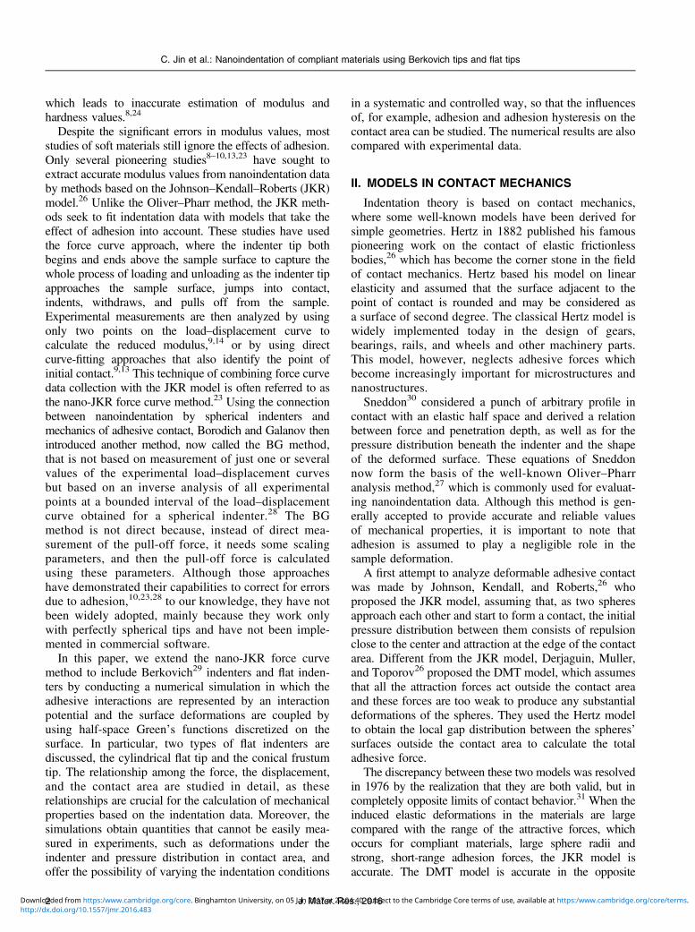
where R is the radius of the sphere indenter as shown inFig 1
FIG 1 The idealized geometries of indenter tips used in the numerical simulations and the corresponding real tips used in the experimentsrespectively
C Jin et al Nanoindentation of compliant materials using Berkovich tips and flat tips
J Mater Res 20164httpdxdoiorg101557jmr2016483Downloaded from httpswwwcambridgeorgcore Binghamton University on 05 Jan 2017 at 220440 subject to the Cambridge Core terms of use available at httpswwwcambridgeorgcoreterms
(ii) Berkovich indenters The geometry of a Berkovichtip is a pyramid having a triangular base as shown inFig 1 The initial air gap for a pyramid with a base of anequilateral triangle with side length m and a height of ncan be written as follows
h0ethx yTHORN frac14nm
ffiffiffi3
pythorn 3jxj
if jxj gt ffiffiffi3
py
2ffiffi3
pnjyj
m otherwise
( eth5THORN
For a Berkovich tip the angle between the centerlineand the three faces is 653deg which gives nm 5 0133
(iii) Cylindrical flat indenters In this case the initialair gap is zero for points (x y) inside the circular regionx2 1 y2 R2 where R is the radius of the cylindrical flatpunch as shown in Fig 1
(iv) Conical frustum indenters A conical frustum isa frustum created by slicing the top off a cone with thecut made parallel to the base For a right circular cone leth be the height and R1 and R2 the base and top radii asshown in Fig 1 Then the initial air gap is zero for points(x y) inside the circular region x2 1 y2 R2
2 and forpoints outside this circular region we have the following
h0ethx yTHORN frac14 h
R1 R2x2 thorn y2 1=2 R2
h i eth6THORN
Theoretically the contact domain X should be infinitebut the pressure decreases very rapidly as the air gapbetween the two surfaces becomes larger and thusthe computational domain can be taken as a finite squareX 5 [a a] [a a] where a is a finite valuerepresenting the size of the computational domain Thetotal normal load f can be written as follows
f frac14ZZ
Xp x yeth THORN dx dy eth7THORN
To implement the formulae into numerical simulationwe then introduce the following dimensionless variablesH D U0 P X Y F and l to transform Eqs (1) (2) and(7) into the following normalized forms
P frac14 83
H thorn 1eth THORN9 H thorn 1eth THORN3h i
eth8aTHORN
H frac14 Dthorn U0
thorn 8l3=2
3p
ZZX
HethX0 Y 0THORN thorn 1frac12 9 HethX0Y 0THORN thorn 1frac12 3ffiffiffiffiffiffiffiffiffiffiffiffiffiffiffiffiffiffiffiffiffiffiffiffiffiffiffiffiffiffiffiffiffiffiffiffiffiffiffiffiffiffiffiffiX X0eth THORN2 thorn Y Y 0eth THORN2
q dX0 dY 0
eth8bTHORN
F frac14 13p
ZZXPethXYTHORN dX dY eth8cTHORN
where H frac14 he 1 D frac14 a
e U0 frac14 h0e and P frac14 pe
Wad
The parameter D is the normalized displacement iethe normalized indentation depth The other four param-eters have different forms for different types of indenters
(i) For a spherical shape we have
F frac14 f3pRWad
X frac14 xffiffiffiffieR
p Y frac14 yffiffiffiffieR
p and l frac14 RW2ad
ETI2e3
1=3
and the initial air gap can be written as
U0ethx yTHORN frac14 X2 thorn Y2
2 eth9THORN
(ii) For a Berkovich shape we have
F frac14 n2f3pm2Wade
X frac14 x nem
Y frac14 y n
em
and l frac14 mWad
nETIe
2=3
Note that nm 5 0133 and the initial air gap can bedescribed as
U0ethx yTHORN frac14ffiffiffi3
pY thorn 3 Xj j if Xj j gt ffiffiffi
3p
Y2
ffiffiffi3
pYj j otherwise
eth10THORN
(iii) For a cylindrical flat shape we have
F frac14 f e3pR2Wad
X frac14 xR Y frac14 y
R and l frac14 RWad
ETIe2 2=3
and theinitial air gap is zero for points (X Y) inside the circularregion X2 thorn Y2 1
(iv) For a conical frustum shape we have
F frac14 f e3pR2
2 Wad X frac14 x
R2 Y frac14 y
R2 and l frac14 R2Wad
ETIe2 2=3
and
the initial air gap is zero for points (X Y) inside thecircular region X2 1 Y2 1 For points outside thiscircular region we have
U0ethx yTHORN frac14 h
R1 R2
R2
e
X2 thorn Y2 1=2 1h i
eth11aTHORN
For example for a conical frustum with a 60deg coneangle we have h=ethR1 R2THORN frac14
ffiffiffi3
p and therefore we
can obtain
U0ethx yTHORN frac14ffiffiffi3
pR2
eX2 thorn Y2 1=2 1h i
eth11bTHORN
The parameter l is the so-called Tabor parameter31
which is often used to determine whether the JKR orDMT model would best describe a contact systemas Greenwood34 concluded that the limits of theMaugisndashDugdale model correspond to Taborrsquos limitswith small values of the Tabor parameter describingmaterial behavior in a DMT-type regime and largevalues of the Tabor parameter describing the contactbehavior for JKR-type regime Note that the Taborparameter has different expressions for different typesof indenters
C Jin et al Nanoindentation of compliant materials using Berkovich tips and flat tips
5J Mater Res 2016httpdxdoiorg101557jmr2016483Downloaded from httpswwwcambridgeorgcore Binghamton University on 05 Jan 2017 at 220440 subject to the Cambridge Core terms of use available at httpswwwcambridgeorgcoreterms
The dimensionless form of Eq (8b) after tessellation ofthe problem domain is shown as follows
H XkYleth THORN frac14 Dthorn U0 Xk Yleth THORN thorn l3=2
pCij XkYleth THORNPij
eth12THORN
where CijethX YTHORN[RR
Xij
dX0 dY 0ffiffiffiffiffiffiffiffiffiffiffiffiffiffiffiffiffiffiffiffiffiffiffiffiffiffiffiXX0eth THORN2thorn YY 0eth THORN2
p is the influence
coefficient and Pij is the normalized pressure To writeEq (12) in a vector form we have the following equation
~H frac14 Dthorn ~U0 thorn l3=2
pC~P eth13THORN
Since we assume that the surface interaction isgoverned by the Lennard-Jones potential ~P is a highlynonlinear function of ~H Even for moderately small meshsize where N 5 100 the number of elements of C will bethe eighth power of ten and so the computation canrapidly become intractable To solve this system of N2
highly nonlinear equations a VSR method has been usedby interposing a virtual dash-pot in the mechanicalsystem Then Eq (13) is transformed into the followingevolution equation for the dynamical system defined by
d~H
dtthorn ~H frac14 Dthorn ~U thorn l3=2
pC~P eth14THORN
The equilibrium solution of this dynamical system isdetermined by d~H=dt frac14~0 which is the solution ofEq (13) In this approach the indentation depth D isgradually increased and the H vector obtained from theprevious step is used as an initial state for computingthe H vector in the next step In each step we let timeevolve until the final state in equilibrium is reached Thismethod accurately plots all the stable equilibria for eachvalue of D In all the simulation cases we first increasethe value of D from the minimum to the maximumindentation depth to simulate the approach process andthen we decrease the value of D back to the minimum tosimulate the detachment process
IV EXPERIMENTAL METHODS
Indents were performed on a single Sylgard 184(Dow Corning Corporation Midland Michigan) poly-dimethylsiloxane (PDMS) elastomeric sample preparedfollowing the manufacturerrsquos instructions In short theSylgard sample was prepared by mixing the PDMSprepolymer base with the curing agent with a weightratio of 101 pouring the mixture into a glass mold andbaking at 70 degC for 3 h The PDMS sample remainedattached to its glass substrate during indentation testing
Indentation was performed using a Hysitron TI-950TriboIndenter (Hysitron Inc Minneapolis Minnesota)
equipped with commercially available diamond tips (Hysi-tron Inc) Four tip geometries were used for testinga 100 lm radius diamond conospherical tip with a 90degcone angle a diamond Berkovich tip a 400 lm radiussapphire spherical tip and a 47 lm radius diamondconical frustum tip with a 60deg cone angle
All indents captured full force curves20 in displacementcontrol (100 lm radius spherical tip and Berkovich tip)or open-loop (nominally force control but withoutfeedback) configuration (400 lm radius spherical tipand flat tip) For displacement control indents theindenter first detected the surface with a setpoint forceof 2 lN then lifted off from the surface at a rate of150 nms to a height of 1800 nm above the surface(well outside the adhesive interaction zone) and finallyindented the sample at a constant displacement rate of50 nms to a maximum depth of 4 lm For open-loopindents after the indenter detected the surface with asetpoint force of 2 lN the tip was manually withdrawnfrom the surface to between 18 and 40 lm from thesurface high enough to bring the tip outside the adhesiveinteraction zone (as indicated by the load on the tipreturning to zero) and then an indent was performedfrom above the surface with an applied load and loadingrate that was sufficient to reach a depth of close to 4 lmwith a similar rate of loading to the displacement-controlled indents
Figure 2 shows typical loadndashdisplacement curvesobtained by indenting 101 PDMS with the four differenttypes of indenters respectively Seven curves are shown
FIG 2 Typical loadndashdisplacement curves obtained by indenting101 PDMS with the four different types of indenters respectivelySeven curves are shown for the 100 lm radius conospherical tip sixcurves are shown for the Berkovich tip five curves are shown forthe 400 lm radius spherical tip and four curves are shown for the50 lm radius conical frustum tip illustrating the high repeatabilityof measurements
C Jin et al Nanoindentation of compliant materials using Berkovich tips and flat tips
J Mater Res 20166httpdxdoiorg101557jmr2016483Downloaded from httpswwwcambridgeorgcore Binghamton University on 05 Jan 2017 at 220440 subject to the Cambridge Core terms of use available at httpswwwcambridgeorgcoreterms
for the 100 lm radius conospherical tip six curves areshown for the Berkovich tip five curves are shown forthe 400 lm radius spherical tip and four curves areshown for the 47 lm radius flat tip In the numericalsimulations both the conospherical tip and the sphericaltip are assumed to be perfectly spherical The flattenedconical tip is often assumed to be a cylindrical flatpunch tip at low displacements and therefore twotypes of flat indenters are simulated the cylindricalflat tip and the conical frustum tip to check if they aresignificantly different All the idealized geometries ofindenter tips used in the numerical simulations and thecorresponding real tips used in the experiments areshown in Fig 1
V RESULTS AND DISCUSSION
A Spherical indenter
For the spherical shape recall that
F frac14 f3pRWad
D frac14 ae P frac14 pe
Wad and l frac14 RW2
ad
ETI2e3
1=3are
used in the numerical simulations We found that whenthe value of Tabor parameter is 15 the numerical resultsagree very well with the analytical solution derived fromthe JKR model as shown in Fig 3(a) which plots thenumerical curves of the normalized force F versus thenormalized displacement D for both attachment anddetachment processes Following the standard conventionin contact mechanics we call the absolute value ofthe minimum force on the loadndashdisplacement curve thepull-off or adhesion force ie Foff From the JKRmodel we can obtain that Foff 5 05 The discrepanciesbetween the numerical results and the analytical solutionwhen the contact radius is small is caused by the factthat when the value of the Tabor parameter is not verysmall eg l 10 the contact and separation betweentwo surfaces does not occur smoothly and there aresudden jumping in or jumping out of contact behav-iors34ndash37 When two bodies move closer from a largeseparation a turning point exists indicating the jumping-on of contacting surfaces when they move infinitesi-mally closer On the other hand when two bodies arepulled off from a contact state the turning pointcorresponds to the jumping-off of contacting surfacesThe middle part between the two turning points repre-sents unstable equilibrium states The relaxation tech-nique we used can only plot the stable solutions Theunstable solutions which cannot be observed in real-world experiments can be obtained by using the Riks arclength method of integration52 but the computationalcost will be significantly increased
One of the advantages of conducting numerical simu-lations is that the pressure distribution within the contactarea can be obtained since there exists no analyticalsolution for the pressure distribution within the contact
region Figure 3(b) plots the distribution of thenormalized pressure P in the simulation domain[40 40] [40 40] when the normalized in-dentation depths are D 5 25 18 10 and 10during approach Positive values of P representcompressive forces between surfaces and the edgeof the contact area can be regarded as the locationof the tensile peak stress which is colored by thedeepest shade of blue in the current color schemeIt can be seen that when the two bodies are approachingeach other from a noncontact state eg at D 5 25the surfaces barely deform with pressure being nearlyzero everywhere As the two bodies approach eachother one step further eg at D 5 18 the surfacesjump to a new equilibrium state suddenly with a nonzerocontact area and the pressure becomes compressive inthe central region and tensile at the contact edge which isconsistent with the results from the previous studies34
A representative loading and unloading forcendashdisplacement curve obtained with the 100 lm radiusconospherical tip is shown in Fig 3(c) The observedadhesion hysteresis shows that the work of adhesionduring approach denoted as Wap
ad is much lower thanthat during detachment denoted as Wde
ad Since we haveFoff 5 05 the values of Wap
ad and Wdead can be calculated
from the measured pull-off force f apoff during approachand f deoff during detachment by using the relationship
Wapad frac14 2
3f apoff
pR and Wdead frac14 2
3f deoff
pR respectively The effectiveYoungrsquos modulus can be calculated based on two datapoints from the unloading portion of the curve f deoff
at adeoff (the point where the unloading curve reachesits minimum force) and f dezero at adezero (the point wherethe unloading force equals zero)923 and the re-lationship obtained from the JKR model
E frac14 095f deoffffiffiffiR
p adezero adeoff 3=2
Since we can measure
that f deoff frac14 3723 lN f apoff frac14 2309 lN andadezero adeoff frac14 1172 nm applying these equations tothe spherical nanoindentation tests on 101 PDMS wecan obtain Wap
ad frac14 0049 Jm2 Wdead frac14 0079 Jm2 and
E frac14 275 MPa all of which are reasonable valuesaccording to our previous experimental experience53
From l frac14 RW2ad
ETI2e3
1=3 we can obtain that
e frac14 RW2ad
l3E2
1=3 Since the observed adhesion hysteresis
shows that Wapad is lower than Wde
ad and we used thesame value of the Tabor parameter to simulate both
the attachment and detachment processes eap frac14 RWap2ad
l3E2
1=3
should be smaller than ede frac14 RWde2ad
l3E2
1=3 Figure 3(c) shows
the forcendashdisplacement curve in a dimensional scale super-imposed with the experimental data
C Jin et al Nanoindentation of compliant materials using Berkovich tips and flat tips
7J Mater Res 2016httpdxdoiorg101557jmr2016483Downloaded from httpswwwcambridgeorgcore Binghamton University on 05 Jan 2017 at 220440 subject to the Cambridge Core terms of use available at httpswwwcambridgeorgcoreterms
A representative loading and unloading forcendashdisplacement curve obtained with the 400 lm radiusspherical tip is shown in Fig 3(d) Since we can
measure that f deoff frac14 14120 lN f apoff frac14 4767 lN andadezero adeoff frac14 1810 nm substituting these values intothe nano-JKR force curve equations we can obtain
FIG 3 (a) The numerical curves of the normalized force F versus the normalized displacement D for spherical indenters for both attachment anddetachment processes It shows that when the value of Tabor parameter is 15 the numerical results agree very well with the analytical solutionderived from the JKR model (b) The distribution of the normalized pressure P in the simulation domain [40 40] [40 40] when thenormalized indentation depth D 5 25 18 10 and 10 during approach (c) The forcendashdisplacement curve in a dimensional scalesuperimposed with the experimental data from nanoindentation tests using the 100 lm radius conospherical tip We found that Wap
ad frac14 0049 Jm2Wde
ad frac14 0079 Jm2 and E frac14 275 MPa (d) The forcendashdisplacement curve in a dimensional scale superimposed with the experimental data fromnanoindentation tests using the 400 lm radius spherical tip We found that Wap
ad frac14 0025 Jm2 Wdead frac14 0075 Jm2 and E frac14 275 MPa which are
fairly consistent with the results obtained from the case of 100 lm radius conospherical tip
C Jin et al Nanoindentation of compliant materials using Berkovich tips and flat tips
J Mater Res 20168httpdxdoiorg101557jmr2016483Downloaded from httpswwwcambridgeorgcore Binghamton University on 05 Jan 2017 at 220440 subject to the Cambridge Core terms of use available at httpswwwcambridgeorgcoreterms
that Wapad frac14 0025 Jm2 Wde
ad frac14 0075 Jm2 andE frac14 275 MPa which are fairly consistent with theresults obtained from the case of the 100 lm radiusconospherical tip Figure 3(d) shows the forcendashdisplacementcurve in a dimensional scale superimposed with theexperimental data
B Berkovich indenter
For the Berkovich shape recall that
F frac14 n2f3pm2Wade
D frac14 ae P frac14 pe
Wad and l frac14 mWad
nETIe
2=3are
used in the numerical simulation Figure 4(a) plots thenumerical simulation curves of the normalized forceF versus the normalized displacement D for both attach-ment and detachment processes when the value of theTabor parameter is equal to 15 Since there exists noanalytical solution for the forcendashdisplacement relation-ship for Berkovich indenters these important valueswill be directly measured from the numerical simula-tion curve The normalized pull-off force can beobtained as Foff 5 021 the unloading force reachesits minimum at Dde
off frac14 159 and when the unloadingforce equals zero Dde
zero frac14 531 These values will beused in calculating Wap
ad Wdead and E The jumping in and
jumping out of contact behaviors are not as obviousbecause during the nanoindentation tests using Berkovichindenters the contact area at a given amount of indentationdepth is much smaller than that during the tests usingspherical indenters
Figure 4(b) plots the distribution of the normalizedpressure P in the simulation domain [67 67] [67 67] when the normalized indentation depthsare D 5 25 25 55 and 75 during approach It canbe seen that when the two bodies are approaching eachother from a noncontact state eg at D 5 25 thesurfaces barely deform with pressure being nearly zeroeverywhere As the two bodies approach each otherfurther eg at D5 25 the surfaces obtain an equilibriumstate with a nonzero contact area For the Berkovich tipthe compressive contact pressure forms a sharp peak at thecenter and therefore the values of the contact pressure atthe center of the contact region become much larger thanthose obtained by using the spherical indenter
A complete loading and unloading forcendashdisplacementcurve obtained with the Berkovich tip has been shown inFig 4(c) Since we have Foff 5 021 the relationship ofWap
ad and Wdead with the measured pull-off force f apoff during
approach and f deoff during detachment can be written as
Wapad frac14 n2f ap
off
063pm2e and Wdead frac14 n2f de
off
063pm2e respectively From
l frac14 mWad
nEe
2=3 frac14 15 we can obtain that e frac14 mWad
184nE Since
Wapad is lower than Wde
ad eap frac14 mWap
ad
184nE should be smaller
than ede frac14 mWdead
184nE We then have the following equationsrespectively
Wapad frac14 292n3f apoffE
pm3
1=2
eth15THORN
Wdead frac14 292n3f deoffE
pm3
1=2
eth16THORN
Since the numerical simulation curve shows thatDde
zero Ddeoff frac14 372 we have adezero adeoff frac14 372e and
then we can obtain the following relationship
adezero adeoff frac14202mWde
ad
nE eth17THORN
As measured from the representative experimentalcurve shown in Fig 4(c) we obtain that f deoff frac14 109 lNf apoff frac14 055 lN and adezero adeoff frac14 472 nm Rememberthat for the Berkovich tip we always have nm 5 0133Substituting these values into Eqs (15)ndash(17) we canobtain that Wap
ad frac14 0055 Jm2 Wdead frac14 0077 Jm2 and
E frac14 248 MPa which are fairly consistent with theresults we obtained from the experiments using thespherical indenter Several factors different in naturecould explain the discrepancy in the modulus resultsFirst slight variations from the ideal geometries used inthe numerical simulations would be expected for the realtips due to blunted points in Berkovich tips and the factthat diamond tips are never perfectly spherical This inturn can lead to some error in modulus calculation whenconducting numerical simulations based on idealized tipgeometries to analyze experimental data collected usingreal tips Second in numerical simulations Derjaguinrsquosapproximation is used to calculate surface tractionswhich is not the exact adhesion If the Derjaguinassumptions are not accepted andor there is friction atthe edge of the contact region then the adhesive forcescan work on tangential displacements and the mode-mixity effects have to be discussed however asBorodich et al noted54 interaction between adhesionand friction under both static and kinetic conditions isstill an open question Finally the formulas used in thenumerical simulation are restricted in the small strainrange and linear elastic material behavior Figure 4(c)shows the forcendashdisplacement curve in a dimensionalscale superimposed with the experimental data
It is important to note that Eqs (15) (16) and (17) canalso be used to determine reduced modulus and work ofadhesion for a compliant material from nanoindentationtests using cube-corner indenter15 As the name implies acube corner tip is a three-sided pyramidal tip with per-pendicular faces like the corner of a cube The centerline-to-face angle is 353deg much sharper than a Berkovichpyramid When the value of the Tabor parameter is 15the numerical simulation results of the normalized force
C Jin et al Nanoindentation of compliant materials using Berkovich tips and flat tips
9J Mater Res 2016httpdxdoiorg101557jmr2016483Downloaded from httpswwwcambridgeorgcore Binghamton University on 05 Jan 2017 at 220440 subject to the Cambridge Core terms of use available at httpswwwcambridgeorgcoreterms
F versus the normalized displacement D for both attach-ment and detachment processes will be the same as thecurve shown in Fig 4(c) which is obtained fromBerkovich indenters however in the case of cube-corner indenters we have nm 5 0408 and therefore
the curve of the dimensional force f versus the dimen-sional displacement a will be different To explore theeffect of different ratios of n and m of a three-sidedpyramidal tip on the dimensional forcendashdisplacementcurve we plot five different curves for nanoindentation
FIG 4 (a) The numerical curves of the normalized force F versus the normalized displacement D for Berkovich indenters for both attachmentand detachment processes The value of Tabor parameter is set to be 15 (b) The distribution of the normalized pressure P in the simulationdomain [67 67] [67 67] when the normalized indentation depth D 5 25 25 55 and 75 during approach (c) The forcendashdisplacementcurve in a dimensional scale superimposed with the experimental data from nanoindentation tests using Berkovich indenters We found thatWap
ad frac14 0055 Jm2 Wdead frac14 0077 Jm2 and E frac14 248 MPa
C Jin et al Nanoindentation of compliant materials using Berkovich tips and flat tips
J Mater Res 201610httpdxdoiorg101557jmr2016483Downloaded from httpswwwcambridgeorgcore Binghamton University on 05 Jan 2017 at 220440 subject to the Cambridge Core terms of use available at httpswwwcambridgeorgcoreterms
tests on a compliant material with Wad 5 0077 Jm2 andE frac14 248 MPa as shown in Fig 5 corresponding tofive different pyramidal tips with nm equal to 02 02503 035 and 04 respectively It can be seen that theabsolute value of the minimum force decreases mono-tonically with increasing values of nm which is consis-tent with experimental observations15
By assuming that the value of the Tabor parameter isequal to 15 the numerical simulations have been so farcarried out only in the JKR adhesion regime55 In theJKR-type contact problems an important assumption isthat the surface interaction is absent outside the contactarea The DMT theory deploys cohesive surface forcesoutside the contact zone while retaining the Hertzianforce-deformation characteristics in the core26 Thisresults in the adhesive stress being zero inside the contactarea and finite outside it To explore the DMT-typeregimes and the JKR-DMT transition regimes nano-indentation tests using Berkovich indenters are simulatedfor five different values of the Tabor parameter 0308 10 12 and 15 Figure 6(a) plots the normalizedforce F versus normalized displacement D Since we
have F frac14 l3=2n3Ef3pm3W2
ad
and D frac14 l3=2nEamWad
Fig 6(b) plots the
normalized force Fl32 versus normalized displacementDl32 which shows that with decreasing values of theTabor parameter the forcendashdisplacement curve goes fromthe JKR regime to the DMT regime37 Figure 6(c) plots aseries of normalized pressure distributions in the simula-tion domain [70 70] [70 70] when the normal-ized indentation depth D 5 100 during approach Thissimulation has been performed by using three differentvalues of the Tabor parameter 03 08 and 10 It can beseen that when the value of the Tabor parameter is smallvery large values of P can be observed at the center of the
contact region Figure 6(d) plots the normalized air gapbetween the indenter surface and the sample surface H inthe simulation domain [70 70] [70 70] whenD 5 100 during approach During loading a clearsink-in effect56 is visible as indicated by the curvedcontact edge which is consistent with experimentalobservations from in situ nanoindentation testing ofPDMS samples using Berkovich tips15
C Cylindrical flat indenter
For the cylindrical flat indenter recall that
F frac14 f e3pR2Wad
D frac14 ae P frac14 pe
Wad and l frac14 RWad
ETIe2 2=3
are usedin the numerical simulation Figure 7(a) plots the numer-ical simulation curves of the normalized force F versusthe normalized displacement D for both attachment anddetachment processes when the value of the Taborparameter is equal to 15 The jumping in and jumpingout of contact behaviors are clearly observed Just like thecase of the Berkovich indenter there exists no analyticalsolution for the forcendashdisplacement relationship and thusthese important values will be directly measured fromthe numerical simulation curve The absolute value ofthe minimum force on the loading curve can be obtainedas Fap
off frac14 021 the normalized pull-off force from theunloading curve can be obtained as Fde
off frac14 025 and theunloading portion is a straight line of slope S 5 0114These three important values will be used in calculat-ing Wap
ad Wdead and E Note that in this case the values
of Fapoff and Fde
off are not exactly the sameA complete loading and unloading forcendashdisplacement
curve obtained with the cylindrical flat tip has beenshown in Fig 7(b) Since we have Fap
off frac14 021 andFdeoff frac14 025 the relationship of Wap
ad and Wdead with
the measured pull-off force f apoff during approach and
f deoff during detachment can be written as Wapad frac14 ef ap
off
063pR2
andWdead frac14 ef de
off
075pR2 respectively From l frac14 RWad
Ee2 2=3 frac14 15
we can obtain that e frac14 RWad
184E 1=2
We then have thefollowing equations respectively
Wapad frac14 f apoff
2073p2ER3
eth18THORN
Wdead frac14 f deoff
2104p2ER3
eth19THORN
Since the unloading portion is a straight line of slopeS 5 0114 we can obtain the following relationship
E frac14 s
551pRS eth20THORN
where s is the slope of the unloading portion measuredfrom the experimental curve As measured from the
FIG 5 Five different loading curves for nanoindentation tests ona compliant material with Wad 5 0077 Jm2 and E frac14 248 MPacorresponding to five different pyramidal tips with nm equal to 02025 03 035 and 04 respectively
C Jin et al Nanoindentation of compliant materials using Berkovich tips and flat tips
11J Mater Res 2016httpdxdoiorg101557jmr2016483Downloaded from httpswwwcambridgeorgcore Binghamton University on 05 Jan 2017 at 220440 subject to the Cambridge Core terms of use available at httpswwwcambridgeorgcoreterms
representative curve shown in Fig 7(b) we obtain thatf deoff frac14 26660 lN f apoff frac14 5135 lN and the slope of theunloading portion can be obtained as s 5 2289Substituting these values along with R 5 47 lm intoEqs (18)ndash(20) we can obtain that Wap
ad frac14 0001 Jm2Wde
ad frac14 0027 Jm2 and E frac14 247 MPa The value of thereduced modulus is fairly consistent with the result weobtained from the experiments using the Berkovichindenter Note that the cylindrical flat indentation modelsie Eqs (18)ndash(20) are accurate only if the flattened tip isperfectly parallel to the sample surface so that full contactis achieved during the indent process but full contact isdifficult to establish experimentally due to the unavoid-able sample tilt with respect to the flat punch surface17
It is interesting to notice that if E is calculated by
assuming there is negligible adhesion and thereforeusing E frac14 s
2R16 almost an identical modulus can be
obtained according to Eq (20) since 551pS 2 Henceadhesion seems to be negligible in this scenario which isconsistent with the extremely low value of Wap
ad (only0001 Jm2) observed during sample approach for thecylindrical flat tip
Figure 7(b) shows the forcendashdisplacement curve ina dimensional scale superimposed with the experimentaldata It can be observed that the simulation curve does nottrack the experimental curve well during the final stagesof retraction of the tip This is because the model assumesthat full contact with the flat tip is maintained throughouttip retraction until pull-off resulting in a linear unloadingcurve until pull-off The experimental curve shows a
FIG 6 (a) The numerical simulation results of the normalized force F versus the normalized displacement D during attachment for Berkovichindenters using five different values of the Tabor parameter 03 08 10 12 and 15 (b) The numerical simulation results of the normalizedforce Fl32 versus the normalized displacement Dl32 during attachment (c) Normalized pressure distributions P in the simulation domain[70 70] [70 70] when the normalized indentation depth D 5 100 during attachment using three different values of Tabor parameter03 08 and 10 (d) Normalized air gap between the two surfaces H in the simulation domain [70 70] [70 70] when the normalizedindentation depth D 5 100 during attachment
C Jin et al Nanoindentation of compliant materials using Berkovich tips and flat tips
J Mater Res 201612httpdxdoiorg101557jmr2016483Downloaded from httpswwwcambridgeorgcore Binghamton University on 05 Jan 2017 at 220440 subject to the Cambridge Core terms of use available at httpswwwcambridgeorgcoreterms
FIG 7 (a) The numerical curves of the normalized force F versus the normalized displacement D for cylindrical flat indenters forboth attachment and detachment processes The value of Tabor parameter is set to be 15 (b) The forcendashdisplacement curve ina dimensional scale superimposed with the experimental data from nanoindentation tests using conical frustum indenters We foundthat Wap
ad frac14 0001 Jm2 Wdead frac14 0027 Jm2 and E frac14 247 MPa (c) The numerical simulation curves of the normalized force F versus
the normalized displacement D for conical frustum indenters for both attachment and detachment processes for three different values ofR2e when the value of the Tabor parameter is equal to 15 (d) The distribution of the normalized pressure P in the simulation domain[20 20] [20 20] for conical frustum indenters when R2
e frac14 5 and R2e frac14 12 as the normalized indentation depths are D 5 50 10
40 and 70 during approach
C Jin et al Nanoindentation of compliant materials using Berkovich tips and flat tips
13J Mater Res 2016httpdxdoiorg101557jmr2016483Downloaded from httpswwwcambridgeorgcore Binghamton University on 05 Jan 2017 at 220440 subject to the Cambridge Core terms of use available at httpswwwcambridgeorgcoreterms
linear region at the beginning of the unloading curveindicating a constant area of contact during initial tipretraction but becomes nonlinear as the load approaches0 lN This nonlinearity suggests that the contact size isgradually changing during the later stages of retractionwhich would be expected if the tip is not perfectlyparallel to the sample surface and the tip detaches fromthe sample gradually rather than breaking the entirecircular contact at once
D Conical frustum indenter
For the conical frustum indenter recall thatF frac14 f e
3pR22 Wad
D frac14 ae P frac14 pe
Wad and l frac14 R2Wad
ETIe2 2=3
areused in the numerical simulation Figure 7(c) plots thenumerical simulation curves of the normalized force Fversus the normalized displacement D for both attach-ment and detachment processes for three different valuesof R2
e when the value of the Tabor parameter is equal to15 It can be seen that when R2
e $ 50 the numericalsimulation curve shows almost no difference from theone we obtained from the case of the cylindrical flat tipFrom the simulation for the cylindrical flat tip weobtained that Wap
ad frac14 0001 Jm2 Wdead frac14 0027 Jm2
and E frac14 247 MPa Substituting these values into
l frac14 R2Wad
Ee2 2=3 frac14 15 we can obtain that R2
eap frac14 462 andR2ede frac14 89 both of which are larger than 50 indicating thatthe conical frustum tip we used in the experiments can besafely regarded as a cylindrical flat punch for shallowindentations When R2
e frac14 5 the numerical simulationcurve shows obvious deviation from the curve for thecylindrical flat tip and therefore in this case the conicalfrustum tip cannot be considered as a cylindrical flatpunch even for shallow indentations Figure 7(d) plotsthe distribution of the normalized pressure P in thesimulation domain [20 20] [20 20] whenR2e frac14 5 and R2
e frac14 12 as the normalized indentation depthsare D 5 50 10 40 and 70 during approachrespectively The plots suggest that when the valueof R2
e is small eg R2e frac14 5 the sample contacts not only
the flattened end of the conical frustum tip but also thesides of the cone during indentation consistent with thereported experimental results for indentation of poly-acrylamide hydrogels using a conical frustum tip at largeindentation depths19 As the value of R2
e is increased from5 to 12 a smaller part of the sides of the cone comes incontact with the sample
E Comparison with existing literature
The reduced modulus values determined from theexperimental data reported in this study range from247 to 275 MPa The mechanical properties of Sylgard184 PDMS have been shown to be sensitive to the weightpercentage of the crosslinker curing time and curing
temperature so the mechanical properties of the PDMSsamples from different batches may not be exactlythe same For example one study on 101 Sylgard184 PDMS conducted by Johnston et al57 showed thatthe elastic modulus increased from 132 to 297 MPa ascuring temperature increased from 25 degC to 200 degCThis range of moduli correspond to reduced modulusvalues between 176 and 396 MPa if m 5 05 isassumed A mean reduced modulus of 273 MPa wasreported for the samples cured for 48 min at 100 degCwhich is quite consistent with the values presented inthe current study In another study Sharfeddin et al58
measured elastic properties of Sylgard 184 PDMS samplesat different scales with the 101 to 501 elastomer baseto the curing agent ratios Macroscopic compression andtension tests were compared with the nano-JKR forcecurve method applied to spherical microindentation testsThey showed that the PDMS elastic modulus varied asa sigmoid function with the crosslinking percentage foreach type of test For 101 PDMS samples cured for 20 hat 65 degC they reported that the mean reduced modulus wasapproximately 233 MPa (if m 5 05 is assumed) based onthe results from both macroscale compression tests andmicroscale indentation tests which is quite close to theresults reported here
Since the values of Wapad and Wde
ad depend on the rate atwhich the contact area is increasing and decreasing59
respectively it is expected that the values Wapad and
Wdead will be different for different shapes of indenters
The values of Wapad and Wde
ad obtained from the sphericalnanoindentation in the current study are found to be fairlyconsistent with the values in the existing literature Forexample Yu et al60 conducted more than one hundredJKR experiments by using a dynamical mechanicalanalyzer to measure the values of Wap
ad and Wdead of
Sylgard 184 PDMS samples with five different mixingratios They showed that the measured values of Wap
ad
and Wdead for 101 PDMS cured for 24 h at 120 degC were
0040ndash0044 Jm2 and 0061ndash0068 Jm2 respectively
VI CONCLUSION
In this paper we have successfully extended the nano-JKR force curve method to include Berkovich indentersand flat indenters by conducting a numerical simulationin which the adhesive interactions are represented by aninteraction potential and the surface deformations arecoupled by using half-space Greenrsquos functions discretizedon the surface This method provides a valuable approachto analyze tip-sample contacts to polymers or othercompliant materials The good agreement between theexperimental data and the theoretical prediction haveconfirmed that this approach can be used to accuratelydetermine reduced modulus and work of adhesion duringboth approach and detachment for a compliant polymer
C Jin et al Nanoindentation of compliant materials using Berkovich tips and flat tips
J Mater Res 201614httpdxdoiorg101557jmr2016483Downloaded from httpswwwcambridgeorgcore Binghamton University on 05 Jan 2017 at 220440 subject to the Cambridge Core terms of use available at httpswwwcambridgeorgcoreterms
under conditions where there are strong adhesive forcesbetween the tip and the sample The DMT-type and JKR-type-to-DMT-type transition regimes have been exploredby conducting the simulations using smaller values ofTabor parameters and those results can be used to studycontact problems involving stiff materials small sphereradii and weak long-range adhesion forces This numer-ical simulation package can be easily extended to studynanoindentation tests using other types of indenters suchas cube-corner indenters Vickers indenters61 Knoopindenters62 and conical indenters which will be ofsignificant importance for mechanical characterizationof polymeric and biological materials However theresults presented in this paper assume that the contactingmaterials have well-defined elastic constants In factmost materials have at least some viscoelastic characterand in our future work these effects will be taken intoaccount
ACKNOWLEDGMENTS
This work is supported by start-up funds provided bythe Department of Mechanical Engineering at StateUniversity of New York at Binghamton The nano-indenter used in this study was obtained through thesupport of the National Science Foundation (MRI-1040319) Conclusions and recommendations expressedin this paper are those of the authors and do notnecessarily reflect the views of the National ScienceFoundation
REFERENCES
1 ISO standard 14577 Metallic materialsmdashInstrumented indentationtest for hardness and materials parameter Part 1 part 2 and part 32003 part 4 2007
2 DM Ebenstein and LA Pruitt Nanoindentation of biologicalmaterials Nano Today 1 26 (2006)
3 DM Ebenstein Nanoindentation of soft tissues and otherbiological materials In Handbook of Nanoindentation withBiological Applications ML Oyen ed (Pan Stanford PublishingSingapore 2010) p 350
4 JD Kaufman GJ Miller EF Morgan and CM KlapperichTime-dependent mechanical characterization of poly(2-hydroxyethyl methacrylate) hydrogels using nanoindentation andunconfined compression J Mater Res 23 1472 (2008)
5 JD Kaufman and CM Klapperich Surface detection errorscause overestimation of the modulus in nanoindentation on softmaterials J Mech Behav Biomed Mater 2 312 (2009)
6 J Deuschle S Enders and E Arzt Surface detection in nano-indentation of soft polymers J Mater Res 22 3107 (2007)
7 MR Van Landingham JS Villarrubia WF Guthrie andGF Meyers Nanoindentation of polymers An overview MacromolSymp 167 15 (2001)
8 F Carrillo S Gupta M Balooch SJ Marshall GW MarshallL Pruitt and CM Puttlitz Nanoindentation of polydimethylsi-loxane elastomers Effect of crosslinking work of adhesion andfluid environment on elastic modulus J Mater Res 20 2820(2005)
9 DM Ebenstein and KJ Wahl A comparison of JKR-basedmethods to analyze quasi-static and dynamic indentation forcecurves J Colloid Interface Sci 298 652 (2006)
10 S Gupta F Carrillo C Li L Pruitt and C Puttlitz Adhesiveforces significantly affect elastic modulus determination of softpolymeric materials in nanoindentation Mater Lett 61 448(2007)
11 O Franke M Goken and AM Hodge The nanoindentation ofsoft tissue Current and developing approaches JOM 60 49(2008)
12 B Tang and AHW Ngan Nanoindentation measurement ofmechanical properties of soft solid covered by a thin liquid filmSoft Matter 5 169 (2007)
13 YF Cao DH Yang and W Soboyejoy Nanoindentationmethod for determining the initial contact and adhesion character-istics of soft polydimethylsiloxane J Mater Res 20 2004 (2005)
14 JC Grunlan X Xinyun D Rowenhorst and WW GerberichPreparation and evaluation of tungsten tips relative to diamond fornanoindentation of soft materials Rev Sci Instrum 72 2804(2001)
15 JK Deuschle G Buerki HM Deuschle S Enders J Michlerand E Arzt In situ indentation testing of elastomers Acta Mater56 4390 (2008)
16 Z Wang AA Volinsky and ND Gallant Nanoindentationstudy of polydimethylsiloxane elastic modulus using Berkovichand flat punch tips J Appl Polym Sci 132 41384 (2015)
17 F De Paoli and AA Volinsky Obtaining full contact formeasuring polydimethylsiloxane mechanical properties with flatpunch nanoindentation MethodsX 2 374 (2015)
18 CM Buffinton KJ Tong RA Blaho EM Buffinton andDM Ebenstein Comparison of mechanical testing methods forbiomaterials Pipette aspiration nanoindentation and macroscaletesting J Mech Behav Biomed Mater 51 367 (2015)
19 KJ Tong and DM Ebenstein Comparison of spherical and flattips for indentation of hydrogels JOM 67 713 (2015)
20 JC Kohn and DM Ebenstein Eliminating adhesion errors innanoindentation of compliant polymers and hydrogels J MechBehav Biomed Mater 20 316 (2013)
21 VL Ferguson AJ Bushby and A Boyde Nanomechanicalproperties and mineral concentration in articular calcified cartilageand subchondral bone J Anat 203 191 (2003)
22 PL Leong and EF Morgan Measurement of fracture callusmaterial properties via nanoindentation Acta Biomaterialia 41569 (2008)
23 DM Ebenstein Nano-JKR force curve method overcomeschallenges of surface detection and adhesion for nanoindentationof a compliant polymer in air and water J Mater Res 28 1026(2011)
24 F Alisafaei C-S Han and SHR Sanei On the time andindentation depth dependence of hardness dissipation and stiff-ness in poly-dimethylsiloxane Polym Test 32 1220 (2013)
25 C Klapperich L Pruitt and K Komvopoulos Nanomechanicalproperties of energetically treated polyethylene surfaces J MaterRes 17 423 (2002)
26 KL Johnson Contact Mechanics (Cambridge University PressCambridge 1985)
27 WC Oliver and GM Pharr An improved technique fordetermining hardness and elastic modulus using load and dis-placement sensing indentation experiments J Mater Res 7 1564(1992)
28 FM Borodich and BA Galanov Non-direct estimations ofadhesive and elastic properties of materials by depth-sensingindentation Proc R Soc Ser A 464 2759 (2008)
29 ES Berkovich Three-faced diamond pyramid for micro-hardnesstesting Int Diamond Rev 11 129 (1951)
C Jin et al Nanoindentation of compliant materials using Berkovich tips and flat tips
15J Mater Res 2016httpdxdoiorg101557jmr2016483Downloaded from httpswwwcambridgeorgcore Binghamton University on 05 Jan 2017 at 220440 subject to the Cambridge Core terms of use available at httpswwwcambridgeorgcoreterms
30 IA Sneddon The relation between load and penetration in theaxisymmetric boussinesq problem for a punch of arbitrary profileInt J Eng Sci 3 47 (1965)
31 D Tabor Surface forces and surface interactions J ColloidInterface Sci 58 2 (1977)
32 E Barthel Adhesive elastic contacts JKR and more J Phys DAppl Phys 41 163001 (2008)
33 VM Muller VS Yushchenko and BV Derjaguin On theinfluence of molecular forces on the deformation of an elasticsphere and its sticking to a rigid plane J Colloid Interface Sci 7791 (1980)
34 JA Greenwood Adhesion of elastic spheres Proc R SocLondon Ser A 453 1277 (1997)
35 BA Galanov Development of analytical and numericalmethods for study of models of materials In Report for theProject 70600001-92 70600015-92 (Institute for Problems inMaterials Science Kiev Ukrainian 1993)
36 FM Borodich Hertz type contact problems for power-law shapedbodies In Contact Problems The Legacy of LA GalinGML Gladwell ed (Springer Dordrecht Netherlands 2008)p 261
37 FM Borodich The Hertz-type and adhesive contact problems fordepth-sensing indentation Adv Appl Mech 47 225 (2014)
38 C Jin A Jagota and C-Y Hui An easy-to-implement numericalsimulation method for adhesive contact problems involvingasymmetric adhesive contact J Phys D Appl Phys 44405303 (2011)
39 AE Giannakopoulos P-L Larsson and R Vestregaard Analysisof Vickers indentation Int J Solids Struct 31 2670 (1994)
40 P-L Larsson AE Giannakopoulos E Soderlund DJ Rowcliffeand R Vestergaard Analysis of Berkovich indentation Int JSolids Struct 33 221 (1996)
41 T Chudoba and N Jennett Higher accuracy analysis of instru-mented indentation data obtained with pointed indenters J PhysD Appl Phys 41 215407 (2008)
42 JN Israelachvili Intermolecular and Surface Forces 2nd ed(Academic San Diego 1992)
43 C-Y Hui A Jagota SJ Bennison and JD Londono Crackblunting and the strength of soft elastic solids Proc R SocLondon Ser A 459 1489 (2003)
44 T Tang CY Hui A Jagota and MK Chaudhury Thermalfluctuations limit the adhesive strength of compliant solids JAdhes 82 671 (2006)
45 KL Johnson and JA Greenwood An adhesion map for thecontact of elastic spheres J Colloid Interface Sci 192 326(1997)
46 L Kogut and I Etsion Adhesion in elastic-plastic sphericalmicrocontact J Colloid Interface Sci 261 372 (2003)
47 Y Du L Chen NE McGruer GG Adams and I Etsion Afinite element model of loading and unloading of an asperity
contact with adhesion and plasticity J Colloid Interface Sci 312522 (2007)
48 Z Song and K Komvopoulos Adhesion-induced instabilities inelastic and elasticndashplastic contacts during single and repetitivenormal loading J Mech Phys Solids 59 884 (2011)
49 A Jagota and C Argento An intersurface stress tensor J ColloidInterface Sci 191 326 (1997)
50 N Yu and A Polycarpou Adhesive contact based on theLennardndashJones potential A correction to the value of theequilibrium distance as used in the potential J Colloid InterfaceSci 278 428 (2004)
51 FM Borodich BA Galanov LM Keer andMM Suarez-Alvarez The JKR-type adhesive contact prob-lems for transversely isotropic elastic solids Mech Mater 7534 (2014)
52 M Fafard and B Massicotte Geometrical interpretation of thearc-length method Comput Struct 46 603 (1993)
53 C Jin K Khare S Vajpayee S Yang A Jagota and C-Y HuiAdhesive contact between a rippled elastic surface and a rigidspherical indenter From partial to full contact Soft Matter 710728 (2011)
54 FM Borodich BA Galanov and MM Suarez-AlvarezThe JKR-type adhesive contact problems for power-law shapedaxisymmetric punches J Mech Phys Solids 68 14 (2014)
55 R Spolenak S Gorb H Gao and E Arzt Effects of contactshape on biological attachments Proc R Soc London Ser A 461305 (2005)
56 KW McElhaney JJ Vlassak and WD Nix Determination ofindenter tip geometry and indentation contact area for depth-sensing indentation experiments J Mater Res 13 1300(1998)
57 ID Johnston DK McCluskey CKL Tan and MC TraceyMechanical characterization of bulk Sylgard 184 for microfluidicsand microengineering J Micromech Microeng 24 035017(2014)
58 A Sharfeddin AA Volinsky G Mohan and ND GallantComparison of the macroscale and microscale tests for measuringelastic properties of polydimethylsiloxane J Appl Polym Sci132 42680 (2015)
59 KR Shull Contact mechanics and the adhesion of soft solidsMater Sci Eng R 36 1 (2002)
60 YL Yu D Sanchez and NS Lu Work of adhesionseparationbetween soft elastomers of different mixing ratios J Mater Res30 2702 (2015)
61 RL Smith and GE Sutherland Some notes on the use ofa diamond pyramid for hardness testing Iron Steel Inst 1 285(1925)
62 F Knoop CG Peters and WB Emerson A sensitive pyramidal-diamond tool for indentation measurements J Res Natl BurStand 23 39 (1939)
C Jin et al Nanoindentation of compliant materials using Berkovich tips and flat tips
J Mater Res 201616httpdxdoiorg101557jmr2016483Downloaded from httpswwwcambridgeorgcore Binghamton University on 05 Jan 2017 at 220440 subject to the Cambridge Core terms of use available at httpswwwcambridgeorgcoreterms
which leads to inaccurate estimation of modulus andhardness values824
Despite the significant errors in modulus values moststudies of soft materials still ignore the effects of adhesionOnly several pioneering studies8ndash101323 have sought toextract accurate modulus values from nanoindentation databy methods based on the JohnsonndashKendallndashRoberts (JKR)model26 Unlike the OliverndashPharr method the JKR meth-ods seek to fit indentation data with models that take theeffect of adhesion into account These studies have usedthe force curve approach where the indenter tip bothbegins and ends above the sample surface to capture thewhole process of loading and unloading as the indenter tipapproaches the sample surface jumps into contactindents withdraws and pulls off from the sampleExperimental measurements are then analyzed by usingonly two points on the loadndashdisplacement curve tocalculate the reduced modulus914 or by using directcurve-fitting approaches that also identify the point ofinitial contact913 This technique of combining force curvedata collection with the JKR model is often referred to asthe nano-JKR force curve method23 Using the connectionbetween nanoindentation by spherical indenters andmechanics of adhesive contact Borodich and Galanov thenintroduced another method now called the BG methodthat is not based on measurement of just one or severalvalues of the experimental loadndashdisplacement curvesbut based on an inverse analysis of all experimentalpoints at a bounded interval of the loadndashdisplacementcurve obtained for a spherical indenter28 The BGmethod is not direct because instead of direct mea-surement of the pull-off force it needs some scalingparameters and then the pull-off force is calculatedusing these parameters Although those approacheshave demonstrated their capabilities to correct for errorsdue to adhesion102328 to our knowledge they have notbeen widely adopted mainly because they work onlywith perfectly spherical tips and have not been imple-mented in commercial software
In this paper we extend the nano-JKR force curvemethod to include Berkovich29 indenters and flat inden-ters by conducting a numerical simulation in which theadhesive interactions are represented by an interactionpotential and the surface deformations are coupled byusing half-space Greenrsquos functions discretized on thesurface In particular two types of flat indenters arediscussed the cylindrical flat tip and the conical frustumtip The relationship among the force the displacementand the contact area are studied in detail as theserelationships are crucial for the calculation of mechanicalproperties based on the indentation data Moreover thesimulations obtain quantities that cannot be easily mea-sured in experiments such as deformations under theindenter and pressure distribution in contact area andoffer the possibility of varying the indentation conditions
in a systematic and controlled way so that the influencesof for example adhesion and adhesion hysteresis on thecontact area can be studied The numerical results are alsocompared with experimental data
II MODELS IN CONTACT MECHANICS
Indentation theory is based on contact mechanicswhere some well-known models have been derived forsimple geometries Hertz in 1882 published his famouspioneering work on the contact of elastic frictionlessbodies26 which has become the corner stone in the fieldof contact mechanics Hertz based his model on linearelasticity and assumed that the surface adjacent to thepoint of contact is rounded and may be considered asa surface of second degree The classical Hertz model iswidely implemented today in the design of gearsbearings rails and wheels and other machinery partsThis model however neglects adhesive forces whichbecome increasingly important for microstructures andnanostructures
Sneddon30 considered a punch of arbitrary profile incontact with an elastic half space and derived a relationbetween force and penetration depth as well as for thepressure distribution beneath the indenter and the shapeof the deformed surface These equations of Sneddonnow form the basis of the well-known OliverndashPharranalysis method27 which is commonly used for evaluat-ing nanoindentation data Although this method is gen-erally accepted to provide accurate and reliable valuesof mechanical properties it is important to note thatadhesion is assumed to play a negligible role in thesample deformation
A first attempt to analyze deformable adhesive contactwas made by Johnson Kendall and Roberts26 whoproposed the JKR model assuming that as two spheresapproach each other and start to form a contact the initialpressure distribution between them consists of repulsionclose to the center and attraction at the edge of the contactarea Different from the JKR model Derjaguin Mullerand Toporov26 proposed the DMT model which assumesthat all the attraction forces act outside the contact areaand these forces are too weak to produce any substantialdeformations of the spheres They used the Hertz modelto obtain the local gap distribution between the spheresrsquosurfaces outside the contact area to calculate the totaladhesive force
The discrepancy between these two models was resolvedin 1976 by the realization that they are both valid but incompletely opposite limits of contact behavior31 When theinduced elastic deformations in the materials are largecompared with the range of the attractive forces whichoccurs for compliant materials large sphere radii andstrong short-range adhesion forces the JKR model isaccurate The DMT model is accurate in the opposite
C Jin et al Nanoindentation of compliant materials using Berkovich tips and flat tips
J Mater Res 20162httpdxdoiorg101557jmr2016483Downloaded from httpswwwcambridgeorgcore Binghamton University on 05 Jan 2017 at 220440 subject to the Cambridge Core terms of use available at httpswwwcambridgeorgcoreterms
limit ie stiff materials small sphere radii and weak long-range adhesion forces These limits are described quanti-tatively by a dimensionless parameter which is nowreferred to as the Tabor parameter31 interpreted as theratio between the normal elastic deformation caused solelyby adhesion not by the applied load and the spatial rangeof the adhesion forces Some recently developed modelsfor the JKR-DMT transition have been summarized ina comprehensive review by Barthel32
The first numerical simulation for the adhesive contactbetween spheres was presented by Muller et al in 198033
who used the Lennard-Jones potential to model surfaceinteraction and showed a continuous transition fromthe JKR to the DMT theory as the Tabor parameterdecreased A complete numerical solution was obtainedby Greenwood34 who pointed out the existence ofsingular integrands in the governing equation and foundS-shaped load-approach curves for values of Taborparameter greater than one leading to jumps into andout of contact
All the above-mentioned research focuses on thecontact problems between two spheres or between asphere and a half space To our knowledge only a fewstudies have been focusing on the JKR-type adhesivecontact involving more general shapes An extension ofthe JKR adhesive frictionless contact problem to mono-mial punches was first obtained by Galanov in 199335
In the same year Borodich provided another derivationof Galanovrsquos solution however it was published muchlater36 Some recent results related to the generalizationof JKR theory for axisymmetric adhesive contact prob-lems have been reviewed by Borodich37
For the contact problems involving non-axisymmetricshapes the absence of radial symmetry presents signif-icant difficulty in the numerical simulation because thenumber of nonlinear equations increases from N to N2 asdiscussed Sec III In this paper we use a numericalsimulation method in which the adhesive interactionsare represented by the Lennard-Jones potential and thesurface deformations are coupled by using half-spaceGreenrsquos functions discretized on the surface To solve thissystem of N2 highly nonlinear equations a virtual staterelaxation (VSR) method has been implemented38
Finite element modeling for nanoindentation usingvarious indenter geometries has been attempted withvarying levels of accuracy such as the works ofGiannakopoulos et al39 for the analysis of Vickersindentation Larsson et al40 for the analysis of Berkovichindentation and Chudoba and Jennett41 for the anal-ysis of conical indentation but those simulations donot include the effect of adhesion If the finite elementmethod is used to solve JKR-type adhesive contactproblems a 3D model should be built with a largenumber of cohesive elements applied at the interfaceThe semianalytical approach adopted in this paper
converts a 3D problem to a 2D problem and so thecomputational cost is significantly reduced In our sim-ulation the number of meshes at the contact surface is setto be 512 512 which will be computationally pro-hibitive for commercial finite element software
III NUMERICAL SIMULATION
In this section the governing equations of frictionlessadhesive contact problems involving general shapes willbe presented For surface atomic interaction the empir-ical potential we used is the Lennard-Jones potential42
Hence we can obtain the relationship between the localpressure p and the air gap h as follows
pethhTHORN frac14 8Wad
3ee=heth THORN9 e=heth THORN3
h i eth1THORN
where Wad is the work of adhesion the tensile forceintegrated over the distance necessary to pull apart thetwo bodies and e is a length parameter equal to the rangeof the surface interaction For stiff materials the value ofe should be on the order of interatomic spacing howeverfor compliant materials its value usually becomes muchlarger4344 Equation (1) was first introduced by Johnsonand Greenwood without proof45 and has since been usedin many adhesion studies46ndash48 A detailed derivation ofEq (1) is provided by Jagota and Argento49 and Yu andPolycarpou50 Note that the first term in Eq (1) cor-responds to attraction between the surfaces while thesecond term corresponds to repulsion When the localseparation is smaller than the interatomic distance theshort-range repulsive forces prevail over the attractionforces and the local traction becomes negative Otherwisewhen the local separation is larger than the interatomicdistance the local traction is positive
Derjaguinrsquos approximation34 is then applied toEq (1) This approximation relates the force law betweentwo curved surfaces to the interaction energy per unitarea between two planar surfaces This approximationbecomes a very useful tool since forces between twoplanar bodies are often much easier to calculate Theseparation between the two surfaces due to the surfaceinteraction as well as the applied load denoted by h willbe expressed by the following equation34
h x yeth THORN frac14 athorn ethorn h0 thorn 1pETI
ZZX
p x0 y0eth THORN dx0 dy0x x0eth THORN2 thorn y y0eth THORN2
eth2THORN
where the parameter a is the displacement between thetwo surfaces with respect to the zero force position h5 eie the so-called indentation depth and the parameterETI represents the effective elastic contact modulusNote that ETI has different expressions for different
C Jin et al Nanoindentation of compliant materials using Berkovich tips and flat tips
3J Mater Res 2016httpdxdoiorg101557jmr2016483Downloaded from httpswwwcambridgeorgcore Binghamton University on 05 Jan 2017 at 220440 subject to the Cambridge Core terms of use available at httpswwwcambridgeorgcoreterms
materials For the adhesive contact between two line-arly elastic isotropic materials with Youngrsquos modulusEi and Poissonrsquos ratio mi where i 5 1 2 ETI can beapproximately described by E which is defined as thereduced modulus also termed the effective modulus
1E frac14
1 m21E1
thorn 1 m22E2
eth3aTHORN
For the adhesive contact between a rigid indenter anda transversely isotropic material ETI is more complicatedand can be written as the following equation51
ETI frac14 2D1=2 AC Deth THORNS1 thorn S2eth THORN D 2BDthorn ACeth THORNa11 2D BD ACeth THORNa12frac12
eth3bTHORN
with
A frac14 a13etha11 a12THORNa11a33 a132
B frac14 a13etha13 thorn a44THORN a12a33a11a33 a132
C frac14 a13etha11 a22THORN thorn a11a44a11a33 a132
D frac14 a112 a122
a11a33 a132
S12 frac14
ffiffiffiffiffiffiffiffiffiffiffiffiffiffiffiffiffiffiffiffiffiffiffiffiffiffiffiffiffiffiffiffiffiffiffiffiffiffiffiffiffiffiffiffiffiffiffiffiffiffiffiffiffiffiffiffiffiffiffiffiffiffiffiffiffiAthorn C
2D6
Athorn C
2D
2
1D
1=2
vuut eth3cTHORN
where a11 a12 a13 a33 and a44 are the five elasticconstants for the transversely isotropic material Assume
that the z-axis is normal to the plane of isotropy and thenHookersquos law can be written as follows
e11e22e33e12e13e23
0BBBBBB
1CCCCCCA
frac14
a11 a12 a13 0 0 0a12 a11 a13 0 0 0a13 a13 a13 0 0 00 0 0 a11 a12 0 00 0 0 0 a44=2 00 0 0 0 0 a44=2
26666664
37777775
r11
r22
r33
r12
r13
r23
0BBBBBB
1CCCCCCA
eth3dTHORN
Note that the formulae for numerical simulation for theadhesive contact for transversely isotropic materials havethe same mathematical form as the corresponding for-mulae for isotropic materials except that the effectiveelastic contact modulus ETI has different expression
The parameter h0 in Eq (2) is the initial air gap writtenin rectangular coordinates ie the separation of the twosurfaces in the absence of applied and adhesive forcesThe expression of h0 is different for different types ofindenters
(i) Spherical indenters In the JKR model the geometryof a spherical contact is approximated by a parabolicfunction34
h0ethx yTHORN frac14 x2 thorn y2
2R eth4THORN
where R is the radius of the sphere indenter as shown inFig 1
FIG 1 The idealized geometries of indenter tips used in the numerical simulations and the corresponding real tips used in the experimentsrespectively
C Jin et al Nanoindentation of compliant materials using Berkovich tips and flat tips
J Mater Res 20164httpdxdoiorg101557jmr2016483Downloaded from httpswwwcambridgeorgcore Binghamton University on 05 Jan 2017 at 220440 subject to the Cambridge Core terms of use available at httpswwwcambridgeorgcoreterms
(ii) Berkovich indenters The geometry of a Berkovichtip is a pyramid having a triangular base as shown inFig 1 The initial air gap for a pyramid with a base of anequilateral triangle with side length m and a height of ncan be written as follows
h0ethx yTHORN frac14nm
ffiffiffi3
pythorn 3jxj
if jxj gt ffiffiffi3
py
2ffiffi3
pnjyj
m otherwise
( eth5THORN
For a Berkovich tip the angle between the centerlineand the three faces is 653deg which gives nm 5 0133
(iii) Cylindrical flat indenters In this case the initialair gap is zero for points (x y) inside the circular regionx2 1 y2 R2 where R is the radius of the cylindrical flatpunch as shown in Fig 1
(iv) Conical frustum indenters A conical frustum isa frustum created by slicing the top off a cone with thecut made parallel to the base For a right circular cone leth be the height and R1 and R2 the base and top radii asshown in Fig 1 Then the initial air gap is zero for points(x y) inside the circular region x2 1 y2 R2
2 and forpoints outside this circular region we have the following
h0ethx yTHORN frac14 h
R1 R2x2 thorn y2 1=2 R2
h i eth6THORN
Theoretically the contact domain X should be infinitebut the pressure decreases very rapidly as the air gapbetween the two surfaces becomes larger and thusthe computational domain can be taken as a finite squareX 5 [a a] [a a] where a is a finite valuerepresenting the size of the computational domain Thetotal normal load f can be written as follows
f frac14ZZ
Xp x yeth THORN dx dy eth7THORN
To implement the formulae into numerical simulationwe then introduce the following dimensionless variablesH D U0 P X Y F and l to transform Eqs (1) (2) and(7) into the following normalized forms
P frac14 83
H thorn 1eth THORN9 H thorn 1eth THORN3h i
eth8aTHORN
H frac14 Dthorn U0
thorn 8l3=2
3p
ZZX
HethX0 Y 0THORN thorn 1frac12 9 HethX0Y 0THORN thorn 1frac12 3ffiffiffiffiffiffiffiffiffiffiffiffiffiffiffiffiffiffiffiffiffiffiffiffiffiffiffiffiffiffiffiffiffiffiffiffiffiffiffiffiffiffiffiffiX X0eth THORN2 thorn Y Y 0eth THORN2
q dX0 dY 0
eth8bTHORN
F frac14 13p
ZZXPethXYTHORN dX dY eth8cTHORN
where H frac14 he 1 D frac14 a
e U0 frac14 h0e and P frac14 pe
Wad
The parameter D is the normalized displacement iethe normalized indentation depth The other four param-eters have different forms for different types of indenters
(i) For a spherical shape we have
F frac14 f3pRWad
X frac14 xffiffiffiffieR
p Y frac14 yffiffiffiffieR
p and l frac14 RW2ad
ETI2e3
1=3
and the initial air gap can be written as
U0ethx yTHORN frac14 X2 thorn Y2
2 eth9THORN
(ii) For a Berkovich shape we have
F frac14 n2f3pm2Wade
X frac14 x nem
Y frac14 y n
em
and l frac14 mWad
nETIe
2=3
Note that nm 5 0133 and the initial air gap can bedescribed as
U0ethx yTHORN frac14ffiffiffi3
pY thorn 3 Xj j if Xj j gt ffiffiffi
3p
Y2
ffiffiffi3
pYj j otherwise
eth10THORN
(iii) For a cylindrical flat shape we have
F frac14 f e3pR2Wad
X frac14 xR Y frac14 y
R and l frac14 RWad
ETIe2 2=3
and theinitial air gap is zero for points (X Y) inside the circularregion X2 thorn Y2 1
(iv) For a conical frustum shape we have
F frac14 f e3pR2
2 Wad X frac14 x
R2 Y frac14 y
R2 and l frac14 R2Wad
ETIe2 2=3
and
the initial air gap is zero for points (X Y) inside thecircular region X2 1 Y2 1 For points outside thiscircular region we have
U0ethx yTHORN frac14 h
R1 R2
R2
e
X2 thorn Y2 1=2 1h i
eth11aTHORN
For example for a conical frustum with a 60deg coneangle we have h=ethR1 R2THORN frac14
ffiffiffi3
p and therefore we
can obtain
U0ethx yTHORN frac14ffiffiffi3
pR2
eX2 thorn Y2 1=2 1h i
eth11bTHORN
The parameter l is the so-called Tabor parameter31
which is often used to determine whether the JKR orDMT model would best describe a contact systemas Greenwood34 concluded that the limits of theMaugisndashDugdale model correspond to Taborrsquos limitswith small values of the Tabor parameter describingmaterial behavior in a DMT-type regime and largevalues of the Tabor parameter describing the contactbehavior for JKR-type regime Note that the Taborparameter has different expressions for different typesof indenters
C Jin et al Nanoindentation of compliant materials using Berkovich tips and flat tips
5J Mater Res 2016httpdxdoiorg101557jmr2016483Downloaded from httpswwwcambridgeorgcore Binghamton University on 05 Jan 2017 at 220440 subject to the Cambridge Core terms of use available at httpswwwcambridgeorgcoreterms
The dimensionless form of Eq (8b) after tessellation ofthe problem domain is shown as follows
H XkYleth THORN frac14 Dthorn U0 Xk Yleth THORN thorn l3=2
pCij XkYleth THORNPij
eth12THORN
where CijethX YTHORN[RR
Xij
dX0 dY 0ffiffiffiffiffiffiffiffiffiffiffiffiffiffiffiffiffiffiffiffiffiffiffiffiffiffiffiXX0eth THORN2thorn YY 0eth THORN2
p is the influence
coefficient and Pij is the normalized pressure To writeEq (12) in a vector form we have the following equation
~H frac14 Dthorn ~U0 thorn l3=2
pC~P eth13THORN
Since we assume that the surface interaction isgoverned by the Lennard-Jones potential ~P is a highlynonlinear function of ~H Even for moderately small meshsize where N 5 100 the number of elements of C will bethe eighth power of ten and so the computation canrapidly become intractable To solve this system of N2
highly nonlinear equations a VSR method has been usedby interposing a virtual dash-pot in the mechanicalsystem Then Eq (13) is transformed into the followingevolution equation for the dynamical system defined by
d~H
dtthorn ~H frac14 Dthorn ~U thorn l3=2
pC~P eth14THORN
The equilibrium solution of this dynamical system isdetermined by d~H=dt frac14~0 which is the solution ofEq (13) In this approach the indentation depth D isgradually increased and the H vector obtained from theprevious step is used as an initial state for computingthe H vector in the next step In each step we let timeevolve until the final state in equilibrium is reached Thismethod accurately plots all the stable equilibria for eachvalue of D In all the simulation cases we first increasethe value of D from the minimum to the maximumindentation depth to simulate the approach process andthen we decrease the value of D back to the minimum tosimulate the detachment process
IV EXPERIMENTAL METHODS
Indents were performed on a single Sylgard 184(Dow Corning Corporation Midland Michigan) poly-dimethylsiloxane (PDMS) elastomeric sample preparedfollowing the manufacturerrsquos instructions In short theSylgard sample was prepared by mixing the PDMSprepolymer base with the curing agent with a weightratio of 101 pouring the mixture into a glass mold andbaking at 70 degC for 3 h The PDMS sample remainedattached to its glass substrate during indentation testing
Indentation was performed using a Hysitron TI-950TriboIndenter (Hysitron Inc Minneapolis Minnesota)
equipped with commercially available diamond tips (Hysi-tron Inc) Four tip geometries were used for testinga 100 lm radius diamond conospherical tip with a 90degcone angle a diamond Berkovich tip a 400 lm radiussapphire spherical tip and a 47 lm radius diamondconical frustum tip with a 60deg cone angle
All indents captured full force curves20 in displacementcontrol (100 lm radius spherical tip and Berkovich tip)or open-loop (nominally force control but withoutfeedback) configuration (400 lm radius spherical tipand flat tip) For displacement control indents theindenter first detected the surface with a setpoint forceof 2 lN then lifted off from the surface at a rate of150 nms to a height of 1800 nm above the surface(well outside the adhesive interaction zone) and finallyindented the sample at a constant displacement rate of50 nms to a maximum depth of 4 lm For open-loopindents after the indenter detected the surface with asetpoint force of 2 lN the tip was manually withdrawnfrom the surface to between 18 and 40 lm from thesurface high enough to bring the tip outside the adhesiveinteraction zone (as indicated by the load on the tipreturning to zero) and then an indent was performedfrom above the surface with an applied load and loadingrate that was sufficient to reach a depth of close to 4 lmwith a similar rate of loading to the displacement-controlled indents
Figure 2 shows typical loadndashdisplacement curvesobtained by indenting 101 PDMS with the four differenttypes of indenters respectively Seven curves are shown
FIG 2 Typical loadndashdisplacement curves obtained by indenting101 PDMS with the four different types of indenters respectivelySeven curves are shown for the 100 lm radius conospherical tip sixcurves are shown for the Berkovich tip five curves are shown forthe 400 lm radius spherical tip and four curves are shown for the50 lm radius conical frustum tip illustrating the high repeatabilityof measurements
C Jin et al Nanoindentation of compliant materials using Berkovich tips and flat tips
J Mater Res 20166httpdxdoiorg101557jmr2016483Downloaded from httpswwwcambridgeorgcore Binghamton University on 05 Jan 2017 at 220440 subject to the Cambridge Core terms of use available at httpswwwcambridgeorgcoreterms
for the 100 lm radius conospherical tip six curves areshown for the Berkovich tip five curves are shown forthe 400 lm radius spherical tip and four curves areshown for the 47 lm radius flat tip In the numericalsimulations both the conospherical tip and the sphericaltip are assumed to be perfectly spherical The flattenedconical tip is often assumed to be a cylindrical flatpunch tip at low displacements and therefore twotypes of flat indenters are simulated the cylindricalflat tip and the conical frustum tip to check if they aresignificantly different All the idealized geometries ofindenter tips used in the numerical simulations and thecorresponding real tips used in the experiments areshown in Fig 1
V RESULTS AND DISCUSSION
A Spherical indenter
For the spherical shape recall that
F frac14 f3pRWad
D frac14 ae P frac14 pe
Wad and l frac14 RW2
ad
ETI2e3
1=3are
used in the numerical simulations We found that whenthe value of Tabor parameter is 15 the numerical resultsagree very well with the analytical solution derived fromthe JKR model as shown in Fig 3(a) which plots thenumerical curves of the normalized force F versus thenormalized displacement D for both attachment anddetachment processes Following the standard conventionin contact mechanics we call the absolute value ofthe minimum force on the loadndashdisplacement curve thepull-off or adhesion force ie Foff From the JKRmodel we can obtain that Foff 5 05 The discrepanciesbetween the numerical results and the analytical solutionwhen the contact radius is small is caused by the factthat when the value of the Tabor parameter is not verysmall eg l 10 the contact and separation betweentwo surfaces does not occur smoothly and there aresudden jumping in or jumping out of contact behav-iors34ndash37 When two bodies move closer from a largeseparation a turning point exists indicating the jumping-on of contacting surfaces when they move infinitesi-mally closer On the other hand when two bodies arepulled off from a contact state the turning pointcorresponds to the jumping-off of contacting surfacesThe middle part between the two turning points repre-sents unstable equilibrium states The relaxation tech-nique we used can only plot the stable solutions Theunstable solutions which cannot be observed in real-world experiments can be obtained by using the Riks arclength method of integration52 but the computationalcost will be significantly increased
One of the advantages of conducting numerical simu-lations is that the pressure distribution within the contactarea can be obtained since there exists no analyticalsolution for the pressure distribution within the contact
region Figure 3(b) plots the distribution of thenormalized pressure P in the simulation domain[40 40] [40 40] when the normalized in-dentation depths are D 5 25 18 10 and 10during approach Positive values of P representcompressive forces between surfaces and the edgeof the contact area can be regarded as the locationof the tensile peak stress which is colored by thedeepest shade of blue in the current color schemeIt can be seen that when the two bodies are approachingeach other from a noncontact state eg at D 5 25the surfaces barely deform with pressure being nearlyzero everywhere As the two bodies approach eachother one step further eg at D 5 18 the surfacesjump to a new equilibrium state suddenly with a nonzerocontact area and the pressure becomes compressive inthe central region and tensile at the contact edge which isconsistent with the results from the previous studies34
A representative loading and unloading forcendashdisplacement curve obtained with the 100 lm radiusconospherical tip is shown in Fig 3(c) The observedadhesion hysteresis shows that the work of adhesionduring approach denoted as Wap
ad is much lower thanthat during detachment denoted as Wde
ad Since we haveFoff 5 05 the values of Wap
ad and Wdead can be calculated
from the measured pull-off force f apoff during approachand f deoff during detachment by using the relationship
Wapad frac14 2
3f apoff
pR and Wdead frac14 2
3f deoff
pR respectively The effectiveYoungrsquos modulus can be calculated based on two datapoints from the unloading portion of the curve f deoff
at adeoff (the point where the unloading curve reachesits minimum force) and f dezero at adezero (the point wherethe unloading force equals zero)923 and the re-lationship obtained from the JKR model
E frac14 095f deoffffiffiffiR
p adezero adeoff 3=2
Since we can measure
that f deoff frac14 3723 lN f apoff frac14 2309 lN andadezero adeoff frac14 1172 nm applying these equations tothe spherical nanoindentation tests on 101 PDMS wecan obtain Wap
ad frac14 0049 Jm2 Wdead frac14 0079 Jm2 and
E frac14 275 MPa all of which are reasonable valuesaccording to our previous experimental experience53
From l frac14 RW2ad
ETI2e3
1=3 we can obtain that
e frac14 RW2ad
l3E2
1=3 Since the observed adhesion hysteresis
shows that Wapad is lower than Wde
ad and we used thesame value of the Tabor parameter to simulate both
the attachment and detachment processes eap frac14 RWap2ad
l3E2
1=3
should be smaller than ede frac14 RWde2ad
l3E2
1=3 Figure 3(c) shows
the forcendashdisplacement curve in a dimensional scale super-imposed with the experimental data
C Jin et al Nanoindentation of compliant materials using Berkovich tips and flat tips
7J Mater Res 2016httpdxdoiorg101557jmr2016483Downloaded from httpswwwcambridgeorgcore Binghamton University on 05 Jan 2017 at 220440 subject to the Cambridge Core terms of use available at httpswwwcambridgeorgcoreterms
A representative loading and unloading forcendashdisplacement curve obtained with the 400 lm radiusspherical tip is shown in Fig 3(d) Since we can
measure that f deoff frac14 14120 lN f apoff frac14 4767 lN andadezero adeoff frac14 1810 nm substituting these values intothe nano-JKR force curve equations we can obtain
FIG 3 (a) The numerical curves of the normalized force F versus the normalized displacement D for spherical indenters for both attachment anddetachment processes It shows that when the value of Tabor parameter is 15 the numerical results agree very well with the analytical solutionderived from the JKR model (b) The distribution of the normalized pressure P in the simulation domain [40 40] [40 40] when thenormalized indentation depth D 5 25 18 10 and 10 during approach (c) The forcendashdisplacement curve in a dimensional scalesuperimposed with the experimental data from nanoindentation tests using the 100 lm radius conospherical tip We found that Wap
ad frac14 0049 Jm2Wde
ad frac14 0079 Jm2 and E frac14 275 MPa (d) The forcendashdisplacement curve in a dimensional scale superimposed with the experimental data fromnanoindentation tests using the 400 lm radius spherical tip We found that Wap
ad frac14 0025 Jm2 Wdead frac14 0075 Jm2 and E frac14 275 MPa which are
fairly consistent with the results obtained from the case of 100 lm radius conospherical tip
C Jin et al Nanoindentation of compliant materials using Berkovich tips and flat tips
J Mater Res 20168httpdxdoiorg101557jmr2016483Downloaded from httpswwwcambridgeorgcore Binghamton University on 05 Jan 2017 at 220440 subject to the Cambridge Core terms of use available at httpswwwcambridgeorgcoreterms
that Wapad frac14 0025 Jm2 Wde
ad frac14 0075 Jm2 andE frac14 275 MPa which are fairly consistent with theresults obtained from the case of the 100 lm radiusconospherical tip Figure 3(d) shows the forcendashdisplacementcurve in a dimensional scale superimposed with theexperimental data
B Berkovich indenter
For the Berkovich shape recall that
F frac14 n2f3pm2Wade
D frac14 ae P frac14 pe
Wad and l frac14 mWad
nETIe
2=3are
used in the numerical simulation Figure 4(a) plots thenumerical simulation curves of the normalized forceF versus the normalized displacement D for both attach-ment and detachment processes when the value of theTabor parameter is equal to 15 Since there exists noanalytical solution for the forcendashdisplacement relation-ship for Berkovich indenters these important valueswill be directly measured from the numerical simula-tion curve The normalized pull-off force can beobtained as Foff 5 021 the unloading force reachesits minimum at Dde
off frac14 159 and when the unloadingforce equals zero Dde
zero frac14 531 These values will beused in calculating Wap
ad Wdead and E The jumping in and
jumping out of contact behaviors are not as obviousbecause during the nanoindentation tests using Berkovichindenters the contact area at a given amount of indentationdepth is much smaller than that during the tests usingspherical indenters
Figure 4(b) plots the distribution of the normalizedpressure P in the simulation domain [67 67] [67 67] when the normalized indentation depthsare D 5 25 25 55 and 75 during approach It canbe seen that when the two bodies are approaching eachother from a noncontact state eg at D 5 25 thesurfaces barely deform with pressure being nearly zeroeverywhere As the two bodies approach each otherfurther eg at D5 25 the surfaces obtain an equilibriumstate with a nonzero contact area For the Berkovich tipthe compressive contact pressure forms a sharp peak at thecenter and therefore the values of the contact pressure atthe center of the contact region become much larger thanthose obtained by using the spherical indenter
A complete loading and unloading forcendashdisplacementcurve obtained with the Berkovich tip has been shown inFig 4(c) Since we have Foff 5 021 the relationship ofWap
ad and Wdead with the measured pull-off force f apoff during
approach and f deoff during detachment can be written as
Wapad frac14 n2f ap
off
063pm2e and Wdead frac14 n2f de
off
063pm2e respectively From
l frac14 mWad
nEe
2=3 frac14 15 we can obtain that e frac14 mWad
184nE Since
Wapad is lower than Wde
ad eap frac14 mWap
ad
184nE should be smaller
than ede frac14 mWdead
184nE We then have the following equationsrespectively
Wapad frac14 292n3f apoffE
pm3
1=2
eth15THORN
Wdead frac14 292n3f deoffE
pm3
1=2
eth16THORN
Since the numerical simulation curve shows thatDde
zero Ddeoff frac14 372 we have adezero adeoff frac14 372e and
then we can obtain the following relationship
adezero adeoff frac14202mWde
ad
nE eth17THORN
As measured from the representative experimentalcurve shown in Fig 4(c) we obtain that f deoff frac14 109 lNf apoff frac14 055 lN and adezero adeoff frac14 472 nm Rememberthat for the Berkovich tip we always have nm 5 0133Substituting these values into Eqs (15)ndash(17) we canobtain that Wap
ad frac14 0055 Jm2 Wdead frac14 0077 Jm2 and
E frac14 248 MPa which are fairly consistent with theresults we obtained from the experiments using thespherical indenter Several factors different in naturecould explain the discrepancy in the modulus resultsFirst slight variations from the ideal geometries used inthe numerical simulations would be expected for the realtips due to blunted points in Berkovich tips and the factthat diamond tips are never perfectly spherical This inturn can lead to some error in modulus calculation whenconducting numerical simulations based on idealized tipgeometries to analyze experimental data collected usingreal tips Second in numerical simulations Derjaguinrsquosapproximation is used to calculate surface tractionswhich is not the exact adhesion If the Derjaguinassumptions are not accepted andor there is friction atthe edge of the contact region then the adhesive forcescan work on tangential displacements and the mode-mixity effects have to be discussed however asBorodich et al noted54 interaction between adhesionand friction under both static and kinetic conditions isstill an open question Finally the formulas used in thenumerical simulation are restricted in the small strainrange and linear elastic material behavior Figure 4(c)shows the forcendashdisplacement curve in a dimensionalscale superimposed with the experimental data
It is important to note that Eqs (15) (16) and (17) canalso be used to determine reduced modulus and work ofadhesion for a compliant material from nanoindentationtests using cube-corner indenter15 As the name implies acube corner tip is a three-sided pyramidal tip with per-pendicular faces like the corner of a cube The centerline-to-face angle is 353deg much sharper than a Berkovichpyramid When the value of the Tabor parameter is 15the numerical simulation results of the normalized force
C Jin et al Nanoindentation of compliant materials using Berkovich tips and flat tips
9J Mater Res 2016httpdxdoiorg101557jmr2016483Downloaded from httpswwwcambridgeorgcore Binghamton University on 05 Jan 2017 at 220440 subject to the Cambridge Core terms of use available at httpswwwcambridgeorgcoreterms
F versus the normalized displacement D for both attach-ment and detachment processes will be the same as thecurve shown in Fig 4(c) which is obtained fromBerkovich indenters however in the case of cube-corner indenters we have nm 5 0408 and therefore
the curve of the dimensional force f versus the dimen-sional displacement a will be different To explore theeffect of different ratios of n and m of a three-sidedpyramidal tip on the dimensional forcendashdisplacementcurve we plot five different curves for nanoindentation
FIG 4 (a) The numerical curves of the normalized force F versus the normalized displacement D for Berkovich indenters for both attachmentand detachment processes The value of Tabor parameter is set to be 15 (b) The distribution of the normalized pressure P in the simulationdomain [67 67] [67 67] when the normalized indentation depth D 5 25 25 55 and 75 during approach (c) The forcendashdisplacementcurve in a dimensional scale superimposed with the experimental data from nanoindentation tests using Berkovich indenters We found thatWap
ad frac14 0055 Jm2 Wdead frac14 0077 Jm2 and E frac14 248 MPa
C Jin et al Nanoindentation of compliant materials using Berkovich tips and flat tips
J Mater Res 201610httpdxdoiorg101557jmr2016483Downloaded from httpswwwcambridgeorgcore Binghamton University on 05 Jan 2017 at 220440 subject to the Cambridge Core terms of use available at httpswwwcambridgeorgcoreterms
tests on a compliant material with Wad 5 0077 Jm2 andE frac14 248 MPa as shown in Fig 5 corresponding tofive different pyramidal tips with nm equal to 02 02503 035 and 04 respectively It can be seen that theabsolute value of the minimum force decreases mono-tonically with increasing values of nm which is consis-tent with experimental observations15
By assuming that the value of the Tabor parameter isequal to 15 the numerical simulations have been so farcarried out only in the JKR adhesion regime55 In theJKR-type contact problems an important assumption isthat the surface interaction is absent outside the contactarea The DMT theory deploys cohesive surface forcesoutside the contact zone while retaining the Hertzianforce-deformation characteristics in the core26 Thisresults in the adhesive stress being zero inside the contactarea and finite outside it To explore the DMT-typeregimes and the JKR-DMT transition regimes nano-indentation tests using Berkovich indenters are simulatedfor five different values of the Tabor parameter 0308 10 12 and 15 Figure 6(a) plots the normalizedforce F versus normalized displacement D Since we
have F frac14 l3=2n3Ef3pm3W2
ad
and D frac14 l3=2nEamWad
Fig 6(b) plots the
normalized force Fl32 versus normalized displacementDl32 which shows that with decreasing values of theTabor parameter the forcendashdisplacement curve goes fromthe JKR regime to the DMT regime37 Figure 6(c) plots aseries of normalized pressure distributions in the simula-tion domain [70 70] [70 70] when the normal-ized indentation depth D 5 100 during approach Thissimulation has been performed by using three differentvalues of the Tabor parameter 03 08 and 10 It can beseen that when the value of the Tabor parameter is smallvery large values of P can be observed at the center of the
contact region Figure 6(d) plots the normalized air gapbetween the indenter surface and the sample surface H inthe simulation domain [70 70] [70 70] whenD 5 100 during approach During loading a clearsink-in effect56 is visible as indicated by the curvedcontact edge which is consistent with experimentalobservations from in situ nanoindentation testing ofPDMS samples using Berkovich tips15
C Cylindrical flat indenter
For the cylindrical flat indenter recall that
F frac14 f e3pR2Wad
D frac14 ae P frac14 pe
Wad and l frac14 RWad
ETIe2 2=3
are usedin the numerical simulation Figure 7(a) plots the numer-ical simulation curves of the normalized force F versusthe normalized displacement D for both attachment anddetachment processes when the value of the Taborparameter is equal to 15 The jumping in and jumpingout of contact behaviors are clearly observed Just like thecase of the Berkovich indenter there exists no analyticalsolution for the forcendashdisplacement relationship and thusthese important values will be directly measured fromthe numerical simulation curve The absolute value ofthe minimum force on the loading curve can be obtainedas Fap
off frac14 021 the normalized pull-off force from theunloading curve can be obtained as Fde
off frac14 025 and theunloading portion is a straight line of slope S 5 0114These three important values will be used in calculat-ing Wap
ad Wdead and E Note that in this case the values
of Fapoff and Fde
off are not exactly the sameA complete loading and unloading forcendashdisplacement
curve obtained with the cylindrical flat tip has beenshown in Fig 7(b) Since we have Fap
off frac14 021 andFdeoff frac14 025 the relationship of Wap
ad and Wdead with
the measured pull-off force f apoff during approach and
f deoff during detachment can be written as Wapad frac14 ef ap
off
063pR2
andWdead frac14 ef de
off
075pR2 respectively From l frac14 RWad
Ee2 2=3 frac14 15
we can obtain that e frac14 RWad
184E 1=2
We then have thefollowing equations respectively
Wapad frac14 f apoff
2073p2ER3
eth18THORN
Wdead frac14 f deoff
2104p2ER3
eth19THORN
Since the unloading portion is a straight line of slopeS 5 0114 we can obtain the following relationship
E frac14 s
551pRS eth20THORN
where s is the slope of the unloading portion measuredfrom the experimental curve As measured from the
FIG 5 Five different loading curves for nanoindentation tests ona compliant material with Wad 5 0077 Jm2 and E frac14 248 MPacorresponding to five different pyramidal tips with nm equal to 02025 03 035 and 04 respectively
C Jin et al Nanoindentation of compliant materials using Berkovich tips and flat tips
11J Mater Res 2016httpdxdoiorg101557jmr2016483Downloaded from httpswwwcambridgeorgcore Binghamton University on 05 Jan 2017 at 220440 subject to the Cambridge Core terms of use available at httpswwwcambridgeorgcoreterms
representative curve shown in Fig 7(b) we obtain thatf deoff frac14 26660 lN f apoff frac14 5135 lN and the slope of theunloading portion can be obtained as s 5 2289Substituting these values along with R 5 47 lm intoEqs (18)ndash(20) we can obtain that Wap
ad frac14 0001 Jm2Wde
ad frac14 0027 Jm2 and E frac14 247 MPa The value of thereduced modulus is fairly consistent with the result weobtained from the experiments using the Berkovichindenter Note that the cylindrical flat indentation modelsie Eqs (18)ndash(20) are accurate only if the flattened tip isperfectly parallel to the sample surface so that full contactis achieved during the indent process but full contact isdifficult to establish experimentally due to the unavoid-able sample tilt with respect to the flat punch surface17
It is interesting to notice that if E is calculated by
assuming there is negligible adhesion and thereforeusing E frac14 s
2R16 almost an identical modulus can be
obtained according to Eq (20) since 551pS 2 Henceadhesion seems to be negligible in this scenario which isconsistent with the extremely low value of Wap
ad (only0001 Jm2) observed during sample approach for thecylindrical flat tip
Figure 7(b) shows the forcendashdisplacement curve ina dimensional scale superimposed with the experimentaldata It can be observed that the simulation curve does nottrack the experimental curve well during the final stagesof retraction of the tip This is because the model assumesthat full contact with the flat tip is maintained throughouttip retraction until pull-off resulting in a linear unloadingcurve until pull-off The experimental curve shows a
FIG 6 (a) The numerical simulation results of the normalized force F versus the normalized displacement D during attachment for Berkovichindenters using five different values of the Tabor parameter 03 08 10 12 and 15 (b) The numerical simulation results of the normalizedforce Fl32 versus the normalized displacement Dl32 during attachment (c) Normalized pressure distributions P in the simulation domain[70 70] [70 70] when the normalized indentation depth D 5 100 during attachment using three different values of Tabor parameter03 08 and 10 (d) Normalized air gap between the two surfaces H in the simulation domain [70 70] [70 70] when the normalizedindentation depth D 5 100 during attachment
C Jin et al Nanoindentation of compliant materials using Berkovich tips and flat tips
J Mater Res 201612httpdxdoiorg101557jmr2016483Downloaded from httpswwwcambridgeorgcore Binghamton University on 05 Jan 2017 at 220440 subject to the Cambridge Core terms of use available at httpswwwcambridgeorgcoreterms
FIG 7 (a) The numerical curves of the normalized force F versus the normalized displacement D for cylindrical flat indenters forboth attachment and detachment processes The value of Tabor parameter is set to be 15 (b) The forcendashdisplacement curve ina dimensional scale superimposed with the experimental data from nanoindentation tests using conical frustum indenters We foundthat Wap
ad frac14 0001 Jm2 Wdead frac14 0027 Jm2 and E frac14 247 MPa (c) The numerical simulation curves of the normalized force F versus
the normalized displacement D for conical frustum indenters for both attachment and detachment processes for three different values ofR2e when the value of the Tabor parameter is equal to 15 (d) The distribution of the normalized pressure P in the simulation domain[20 20] [20 20] for conical frustum indenters when R2
e frac14 5 and R2e frac14 12 as the normalized indentation depths are D 5 50 10
40 and 70 during approach
C Jin et al Nanoindentation of compliant materials using Berkovich tips and flat tips
13J Mater Res 2016httpdxdoiorg101557jmr2016483Downloaded from httpswwwcambridgeorgcore Binghamton University on 05 Jan 2017 at 220440 subject to the Cambridge Core terms of use available at httpswwwcambridgeorgcoreterms
linear region at the beginning of the unloading curveindicating a constant area of contact during initial tipretraction but becomes nonlinear as the load approaches0 lN This nonlinearity suggests that the contact size isgradually changing during the later stages of retractionwhich would be expected if the tip is not perfectlyparallel to the sample surface and the tip detaches fromthe sample gradually rather than breaking the entirecircular contact at once
D Conical frustum indenter
For the conical frustum indenter recall thatF frac14 f e
3pR22 Wad
D frac14 ae P frac14 pe
Wad and l frac14 R2Wad
ETIe2 2=3
areused in the numerical simulation Figure 7(c) plots thenumerical simulation curves of the normalized force Fversus the normalized displacement D for both attach-ment and detachment processes for three different valuesof R2
e when the value of the Tabor parameter is equal to15 It can be seen that when R2
e $ 50 the numericalsimulation curve shows almost no difference from theone we obtained from the case of the cylindrical flat tipFrom the simulation for the cylindrical flat tip weobtained that Wap
ad frac14 0001 Jm2 Wdead frac14 0027 Jm2
and E frac14 247 MPa Substituting these values into
l frac14 R2Wad
Ee2 2=3 frac14 15 we can obtain that R2
eap frac14 462 andR2ede frac14 89 both of which are larger than 50 indicating thatthe conical frustum tip we used in the experiments can besafely regarded as a cylindrical flat punch for shallowindentations When R2
e frac14 5 the numerical simulationcurve shows obvious deviation from the curve for thecylindrical flat tip and therefore in this case the conicalfrustum tip cannot be considered as a cylindrical flatpunch even for shallow indentations Figure 7(d) plotsthe distribution of the normalized pressure P in thesimulation domain [20 20] [20 20] whenR2e frac14 5 and R2
e frac14 12 as the normalized indentation depthsare D 5 50 10 40 and 70 during approachrespectively The plots suggest that when the valueof R2
e is small eg R2e frac14 5 the sample contacts not only
the flattened end of the conical frustum tip but also thesides of the cone during indentation consistent with thereported experimental results for indentation of poly-acrylamide hydrogels using a conical frustum tip at largeindentation depths19 As the value of R2
e is increased from5 to 12 a smaller part of the sides of the cone comes incontact with the sample
E Comparison with existing literature
The reduced modulus values determined from theexperimental data reported in this study range from247 to 275 MPa The mechanical properties of Sylgard184 PDMS have been shown to be sensitive to the weightpercentage of the crosslinker curing time and curing
temperature so the mechanical properties of the PDMSsamples from different batches may not be exactlythe same For example one study on 101 Sylgard184 PDMS conducted by Johnston et al57 showed thatthe elastic modulus increased from 132 to 297 MPa ascuring temperature increased from 25 degC to 200 degCThis range of moduli correspond to reduced modulusvalues between 176 and 396 MPa if m 5 05 isassumed A mean reduced modulus of 273 MPa wasreported for the samples cured for 48 min at 100 degCwhich is quite consistent with the values presented inthe current study In another study Sharfeddin et al58
measured elastic properties of Sylgard 184 PDMS samplesat different scales with the 101 to 501 elastomer baseto the curing agent ratios Macroscopic compression andtension tests were compared with the nano-JKR forcecurve method applied to spherical microindentation testsThey showed that the PDMS elastic modulus varied asa sigmoid function with the crosslinking percentage foreach type of test For 101 PDMS samples cured for 20 hat 65 degC they reported that the mean reduced modulus wasapproximately 233 MPa (if m 5 05 is assumed) based onthe results from both macroscale compression tests andmicroscale indentation tests which is quite close to theresults reported here
Since the values of Wapad and Wde
ad depend on the rate atwhich the contact area is increasing and decreasing59
respectively it is expected that the values Wapad and
Wdead will be different for different shapes of indenters
The values of Wapad and Wde
ad obtained from the sphericalnanoindentation in the current study are found to be fairlyconsistent with the values in the existing literature Forexample Yu et al60 conducted more than one hundredJKR experiments by using a dynamical mechanicalanalyzer to measure the values of Wap
ad and Wdead of
Sylgard 184 PDMS samples with five different mixingratios They showed that the measured values of Wap
ad
and Wdead for 101 PDMS cured for 24 h at 120 degC were
0040ndash0044 Jm2 and 0061ndash0068 Jm2 respectively
VI CONCLUSION
In this paper we have successfully extended the nano-JKR force curve method to include Berkovich indentersand flat indenters by conducting a numerical simulationin which the adhesive interactions are represented by aninteraction potential and the surface deformations arecoupled by using half-space Greenrsquos functions discretizedon the surface This method provides a valuable approachto analyze tip-sample contacts to polymers or othercompliant materials The good agreement between theexperimental data and the theoretical prediction haveconfirmed that this approach can be used to accuratelydetermine reduced modulus and work of adhesion duringboth approach and detachment for a compliant polymer
C Jin et al Nanoindentation of compliant materials using Berkovich tips and flat tips
J Mater Res 201614httpdxdoiorg101557jmr2016483Downloaded from httpswwwcambridgeorgcore Binghamton University on 05 Jan 2017 at 220440 subject to the Cambridge Core terms of use available at httpswwwcambridgeorgcoreterms
under conditions where there are strong adhesive forcesbetween the tip and the sample The DMT-type and JKR-type-to-DMT-type transition regimes have been exploredby conducting the simulations using smaller values ofTabor parameters and those results can be used to studycontact problems involving stiff materials small sphereradii and weak long-range adhesion forces This numer-ical simulation package can be easily extended to studynanoindentation tests using other types of indenters suchas cube-corner indenters Vickers indenters61 Knoopindenters62 and conical indenters which will be ofsignificant importance for mechanical characterizationof polymeric and biological materials However theresults presented in this paper assume that the contactingmaterials have well-defined elastic constants In factmost materials have at least some viscoelastic characterand in our future work these effects will be taken intoaccount
ACKNOWLEDGMENTS
This work is supported by start-up funds provided bythe Department of Mechanical Engineering at StateUniversity of New York at Binghamton The nano-indenter used in this study was obtained through thesupport of the National Science Foundation (MRI-1040319) Conclusions and recommendations expressedin this paper are those of the authors and do notnecessarily reflect the views of the National ScienceFoundation
REFERENCES
1 ISO standard 14577 Metallic materialsmdashInstrumented indentationtest for hardness and materials parameter Part 1 part 2 and part 32003 part 4 2007
2 DM Ebenstein and LA Pruitt Nanoindentation of biologicalmaterials Nano Today 1 26 (2006)
3 DM Ebenstein Nanoindentation of soft tissues and otherbiological materials In Handbook of Nanoindentation withBiological Applications ML Oyen ed (Pan Stanford PublishingSingapore 2010) p 350
4 JD Kaufman GJ Miller EF Morgan and CM KlapperichTime-dependent mechanical characterization of poly(2-hydroxyethyl methacrylate) hydrogels using nanoindentation andunconfined compression J Mater Res 23 1472 (2008)
5 JD Kaufman and CM Klapperich Surface detection errorscause overestimation of the modulus in nanoindentation on softmaterials J Mech Behav Biomed Mater 2 312 (2009)
6 J Deuschle S Enders and E Arzt Surface detection in nano-indentation of soft polymers J Mater Res 22 3107 (2007)
7 MR Van Landingham JS Villarrubia WF Guthrie andGF Meyers Nanoindentation of polymers An overview MacromolSymp 167 15 (2001)
8 F Carrillo S Gupta M Balooch SJ Marshall GW MarshallL Pruitt and CM Puttlitz Nanoindentation of polydimethylsi-loxane elastomers Effect of crosslinking work of adhesion andfluid environment on elastic modulus J Mater Res 20 2820(2005)
9 DM Ebenstein and KJ Wahl A comparison of JKR-basedmethods to analyze quasi-static and dynamic indentation forcecurves J Colloid Interface Sci 298 652 (2006)
10 S Gupta F Carrillo C Li L Pruitt and C Puttlitz Adhesiveforces significantly affect elastic modulus determination of softpolymeric materials in nanoindentation Mater Lett 61 448(2007)
11 O Franke M Goken and AM Hodge The nanoindentation ofsoft tissue Current and developing approaches JOM 60 49(2008)
12 B Tang and AHW Ngan Nanoindentation measurement ofmechanical properties of soft solid covered by a thin liquid filmSoft Matter 5 169 (2007)
13 YF Cao DH Yang and W Soboyejoy Nanoindentationmethod for determining the initial contact and adhesion character-istics of soft polydimethylsiloxane J Mater Res 20 2004 (2005)
14 JC Grunlan X Xinyun D Rowenhorst and WW GerberichPreparation and evaluation of tungsten tips relative to diamond fornanoindentation of soft materials Rev Sci Instrum 72 2804(2001)
15 JK Deuschle G Buerki HM Deuschle S Enders J Michlerand E Arzt In situ indentation testing of elastomers Acta Mater56 4390 (2008)
16 Z Wang AA Volinsky and ND Gallant Nanoindentationstudy of polydimethylsiloxane elastic modulus using Berkovichand flat punch tips J Appl Polym Sci 132 41384 (2015)
17 F De Paoli and AA Volinsky Obtaining full contact formeasuring polydimethylsiloxane mechanical properties with flatpunch nanoindentation MethodsX 2 374 (2015)
18 CM Buffinton KJ Tong RA Blaho EM Buffinton andDM Ebenstein Comparison of mechanical testing methods forbiomaterials Pipette aspiration nanoindentation and macroscaletesting J Mech Behav Biomed Mater 51 367 (2015)
19 KJ Tong and DM Ebenstein Comparison of spherical and flattips for indentation of hydrogels JOM 67 713 (2015)
20 JC Kohn and DM Ebenstein Eliminating adhesion errors innanoindentation of compliant polymers and hydrogels J MechBehav Biomed Mater 20 316 (2013)
21 VL Ferguson AJ Bushby and A Boyde Nanomechanicalproperties and mineral concentration in articular calcified cartilageand subchondral bone J Anat 203 191 (2003)
22 PL Leong and EF Morgan Measurement of fracture callusmaterial properties via nanoindentation Acta Biomaterialia 41569 (2008)
23 DM Ebenstein Nano-JKR force curve method overcomeschallenges of surface detection and adhesion for nanoindentationof a compliant polymer in air and water J Mater Res 28 1026(2011)
24 F Alisafaei C-S Han and SHR Sanei On the time andindentation depth dependence of hardness dissipation and stiff-ness in poly-dimethylsiloxane Polym Test 32 1220 (2013)
25 C Klapperich L Pruitt and K Komvopoulos Nanomechanicalproperties of energetically treated polyethylene surfaces J MaterRes 17 423 (2002)
26 KL Johnson Contact Mechanics (Cambridge University PressCambridge 1985)
27 WC Oliver and GM Pharr An improved technique fordetermining hardness and elastic modulus using load and dis-placement sensing indentation experiments J Mater Res 7 1564(1992)
28 FM Borodich and BA Galanov Non-direct estimations ofadhesive and elastic properties of materials by depth-sensingindentation Proc R Soc Ser A 464 2759 (2008)
29 ES Berkovich Three-faced diamond pyramid for micro-hardnesstesting Int Diamond Rev 11 129 (1951)
C Jin et al Nanoindentation of compliant materials using Berkovich tips and flat tips
15J Mater Res 2016httpdxdoiorg101557jmr2016483Downloaded from httpswwwcambridgeorgcore Binghamton University on 05 Jan 2017 at 220440 subject to the Cambridge Core terms of use available at httpswwwcambridgeorgcoreterms
30 IA Sneddon The relation between load and penetration in theaxisymmetric boussinesq problem for a punch of arbitrary profileInt J Eng Sci 3 47 (1965)
31 D Tabor Surface forces and surface interactions J ColloidInterface Sci 58 2 (1977)
32 E Barthel Adhesive elastic contacts JKR and more J Phys DAppl Phys 41 163001 (2008)
33 VM Muller VS Yushchenko and BV Derjaguin On theinfluence of molecular forces on the deformation of an elasticsphere and its sticking to a rigid plane J Colloid Interface Sci 7791 (1980)
34 JA Greenwood Adhesion of elastic spheres Proc R SocLondon Ser A 453 1277 (1997)
35 BA Galanov Development of analytical and numericalmethods for study of models of materials In Report for theProject 70600001-92 70600015-92 (Institute for Problems inMaterials Science Kiev Ukrainian 1993)
36 FM Borodich Hertz type contact problems for power-law shapedbodies In Contact Problems The Legacy of LA GalinGML Gladwell ed (Springer Dordrecht Netherlands 2008)p 261
37 FM Borodich The Hertz-type and adhesive contact problems fordepth-sensing indentation Adv Appl Mech 47 225 (2014)
38 C Jin A Jagota and C-Y Hui An easy-to-implement numericalsimulation method for adhesive contact problems involvingasymmetric adhesive contact J Phys D Appl Phys 44405303 (2011)
39 AE Giannakopoulos P-L Larsson and R Vestregaard Analysisof Vickers indentation Int J Solids Struct 31 2670 (1994)
40 P-L Larsson AE Giannakopoulos E Soderlund DJ Rowcliffeand R Vestergaard Analysis of Berkovich indentation Int JSolids Struct 33 221 (1996)
41 T Chudoba and N Jennett Higher accuracy analysis of instru-mented indentation data obtained with pointed indenters J PhysD Appl Phys 41 215407 (2008)
42 JN Israelachvili Intermolecular and Surface Forces 2nd ed(Academic San Diego 1992)
43 C-Y Hui A Jagota SJ Bennison and JD Londono Crackblunting and the strength of soft elastic solids Proc R SocLondon Ser A 459 1489 (2003)
44 T Tang CY Hui A Jagota and MK Chaudhury Thermalfluctuations limit the adhesive strength of compliant solids JAdhes 82 671 (2006)
45 KL Johnson and JA Greenwood An adhesion map for thecontact of elastic spheres J Colloid Interface Sci 192 326(1997)
46 L Kogut and I Etsion Adhesion in elastic-plastic sphericalmicrocontact J Colloid Interface Sci 261 372 (2003)
47 Y Du L Chen NE McGruer GG Adams and I Etsion Afinite element model of loading and unloading of an asperity
contact with adhesion and plasticity J Colloid Interface Sci 312522 (2007)
48 Z Song and K Komvopoulos Adhesion-induced instabilities inelastic and elasticndashplastic contacts during single and repetitivenormal loading J Mech Phys Solids 59 884 (2011)
49 A Jagota and C Argento An intersurface stress tensor J ColloidInterface Sci 191 326 (1997)
50 N Yu and A Polycarpou Adhesive contact based on theLennardndashJones potential A correction to the value of theequilibrium distance as used in the potential J Colloid InterfaceSci 278 428 (2004)
51 FM Borodich BA Galanov LM Keer andMM Suarez-Alvarez The JKR-type adhesive contact prob-lems for transversely isotropic elastic solids Mech Mater 7534 (2014)
52 M Fafard and B Massicotte Geometrical interpretation of thearc-length method Comput Struct 46 603 (1993)
53 C Jin K Khare S Vajpayee S Yang A Jagota and C-Y HuiAdhesive contact between a rippled elastic surface and a rigidspherical indenter From partial to full contact Soft Matter 710728 (2011)
54 FM Borodich BA Galanov and MM Suarez-AlvarezThe JKR-type adhesive contact problems for power-law shapedaxisymmetric punches J Mech Phys Solids 68 14 (2014)
55 R Spolenak S Gorb H Gao and E Arzt Effects of contactshape on biological attachments Proc R Soc London Ser A 461305 (2005)
56 KW McElhaney JJ Vlassak and WD Nix Determination ofindenter tip geometry and indentation contact area for depth-sensing indentation experiments J Mater Res 13 1300(1998)
57 ID Johnston DK McCluskey CKL Tan and MC TraceyMechanical characterization of bulk Sylgard 184 for microfluidicsand microengineering J Micromech Microeng 24 035017(2014)
58 A Sharfeddin AA Volinsky G Mohan and ND GallantComparison of the macroscale and microscale tests for measuringelastic properties of polydimethylsiloxane J Appl Polym Sci132 42680 (2015)
59 KR Shull Contact mechanics and the adhesion of soft solidsMater Sci Eng R 36 1 (2002)
60 YL Yu D Sanchez and NS Lu Work of adhesionseparationbetween soft elastomers of different mixing ratios J Mater Res30 2702 (2015)
61 RL Smith and GE Sutherland Some notes on the use ofa diamond pyramid for hardness testing Iron Steel Inst 1 285(1925)
62 F Knoop CG Peters and WB Emerson A sensitive pyramidal-diamond tool for indentation measurements J Res Natl BurStand 23 39 (1939)
C Jin et al Nanoindentation of compliant materials using Berkovich tips and flat tips
J Mater Res 201616httpdxdoiorg101557jmr2016483Downloaded from httpswwwcambridgeorgcore Binghamton University on 05 Jan 2017 at 220440 subject to the Cambridge Core terms of use available at httpswwwcambridgeorgcoreterms
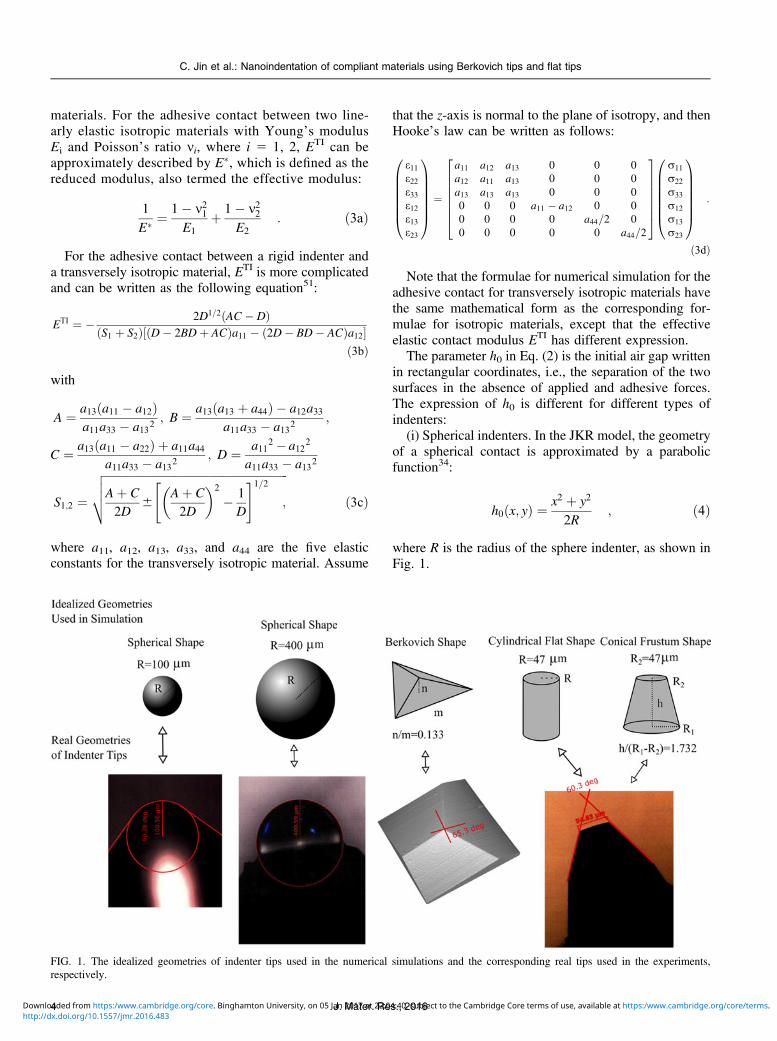
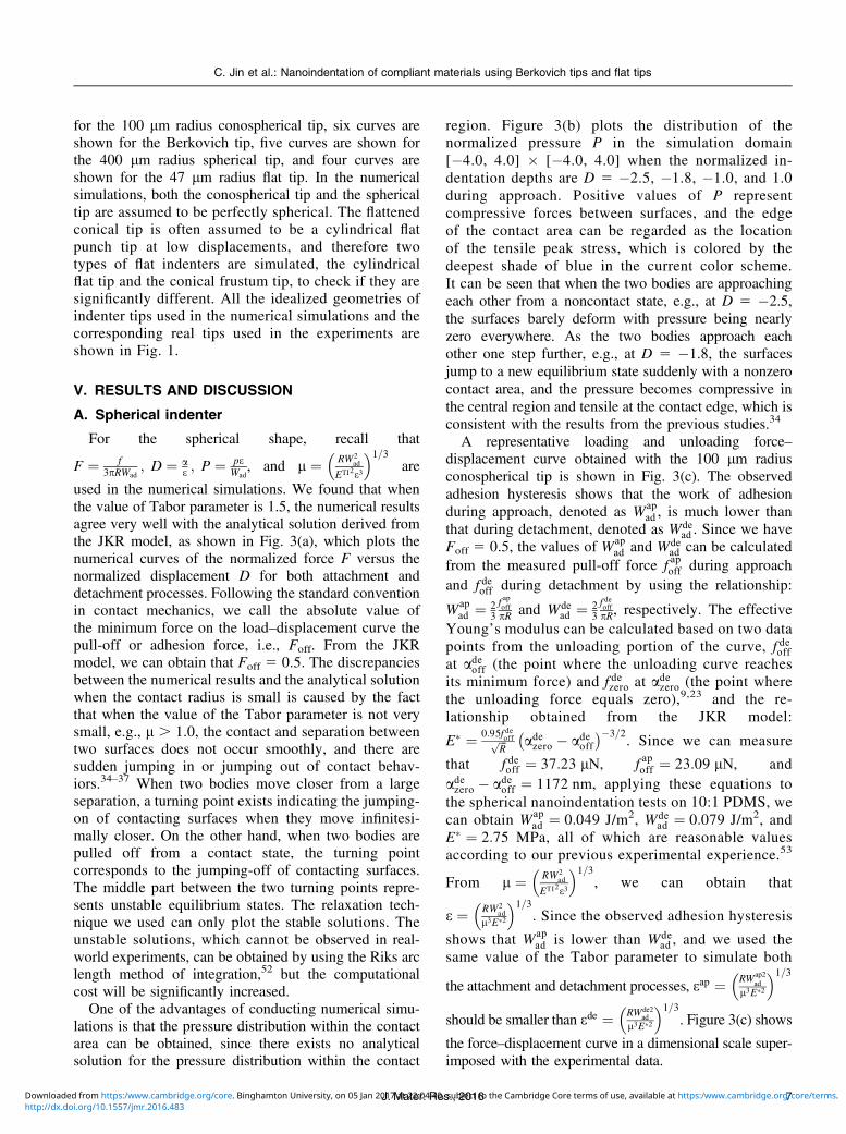
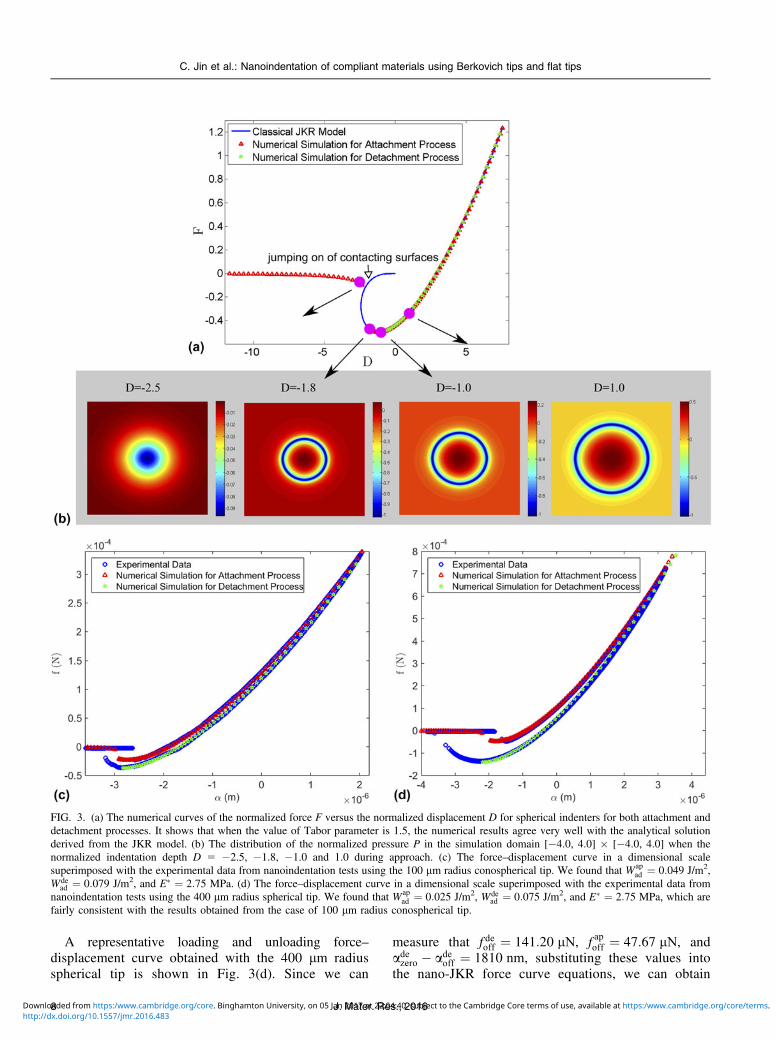
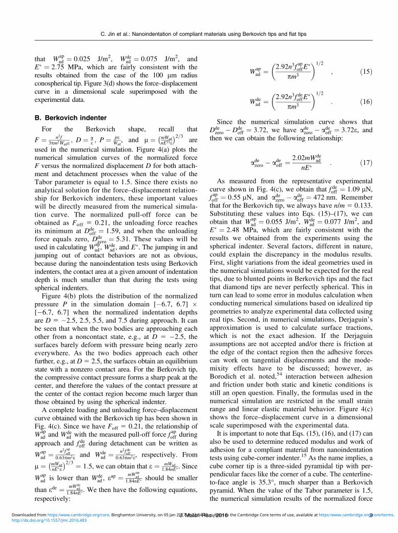
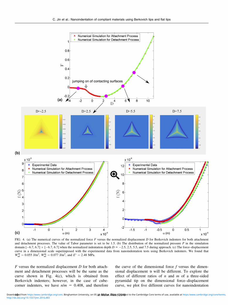
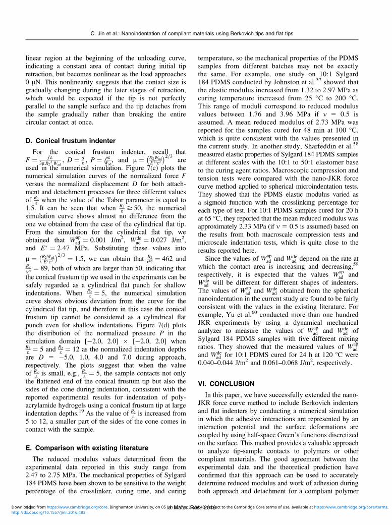
![Numerical investigation of indentation tests on a ...bingweb.binghamton.edu/~cjin/publications/adh.pdf · (JKR) model,[] the Derjaguin–Muller–Toporov (DMT) model,[5 ] and the](https://static.fdocuments.us/doc/165x107/5e6c36f2785f3e2d4323bf4e/numerical-investigation-of-indentation-tests-on-a-cjinpublicationsadhpdf.jpg)