Article Fuzzy PIλ Position Control Method for Permanent ...
14
Article Fuzzy PI λ Position Control Method for Permanent Magnet Synchronous Chongquan Zhong 1 , Lin Wang 1, 2 *, Chuanfang Xu 2, 1 1 Faculty of Electronic Information and Electrical Engineering Dalian University of Technology, Dalian 116023, Liaoning, China; [email protected](C.Z.); [email protected](L.W.); [email protected](C.X.) 2 School of Electronics and Information Engineering Dalian Jiaotong University, Dalian 116028, Liaoning, China * Correspondence: [email protected]; Tel.: +86-0411-8410-6954; Featured Application: This method can be used for motor position control and precise control of industrial robot trajectory. Abstract: Permanent magnet synchronous motor (PMSM) AC servo system shows the characteristics of uncertainty, time-varying and non-linearity, which makes it difficult for traditional PID control to achieve ideal control effect. Fuzzy control has strong adaptability to the problems of parameter variation, non-linearity and model inaccuracy of the controlled object. Vector control strategy is used to study its control principle and the realization of SVPWM. Because the motor object has certain fractional order characteristics, the fuzzy parameter self-tuning PI λ control is chosen as the position regulator of servo motor. It combines the accuracy of fractional order PI control and the adaptability of fuzzy control. A simulation model of PMSM three-closed-loop system is built in MATLAB/Simulink environment. The results show that the control method is effective and can satisfy the trajectory tracking of servo control. Keywords: permanent magnet synchronous motor (PMSM); fuzzy control; SVPWM; Fractional order; PI λ 1. Introduction The existing systems are more or less affected by non-integer order, especially the dynamic processes of large-scale diffusion or heat conduction with memory and heredity. The researches prove that the actual capacitance and inductance are fractional in nature[1]. Permanent magnet synchronous motor (PMSM) is widely used as controlled object in small and medium capacity servo control system because of its simple physical structure, small installation space, low torque ripple and high efficiency. But its strong coupling, non-linearity and fractional order characteristics make AC servo system uncertain and non-linearity[2,3]. Generally, only approximate mathematical model can be established. The traditional PI controller needs to establish accurate mathematical model of the controlled object, which is often difficult to achieve the desired control effect. Fuzzy control transforms the strategy of fuzzy control into a computer-realizable control algorithm. It has strong adaptability to the parameter variation, non-linearity and model inaccuracy of the control object. Considering the control performance index, PMSM control strategy needs to achieve the goals of small current harmonic component, fast speed response and high steady-state accuracy. Liu[4] changed the traditional position, speed and current three-loop control from structure to position-current double-loop control, and proposed a control strategy based on ADRC, which simplified the debugging process. Zuo[5] synthesized the position and speed controllers into the outer loop controllers of the system. An integrated design method of position and speed based on second-order auto-disturbance rejection was proposed, which not only retained the advantages of auto-disturbance rejection control, but also solved the problem of uncontrollable speed. The precise Preprints (www.preprints.org) | NOT PEER-REVIEWED | Posted: 12 November 2019 doi:10.20944/preprints201911.0123.v1 © 2019 by the author(s). Distributed under a Creative Commons CC BY license.
Transcript of Article Fuzzy PIλ Position Control Method for Permanent ...

Article
Fuzzy PIλ Position Control Method for Permanent
Magnet Synchronous
Chongquan Zhong 1, Lin Wang 1, 2 *, Chuanfang Xu 2, 1
1 Faculty of Electronic Information and Electrical Engineering Dalian University of Technology, Dalian
116023, Liaoning, China; [email protected](C.Z.); [email protected](L.W.);
[email protected](C.X.) 2 School of Electronics and Information Engineering Dalian Jiaotong University, Dalian 116028, Liaoning,
China
* Correspondence: [email protected]; Tel.: +86-0411-8410-6954;
Featured Application: This method can be used for motor position control and precise control of
industrial robot trajectory.
Abstract: Permanent magnet synchronous motor (PMSM) AC servo system shows the
characteristics of uncertainty, time-varying and non-linearity, which makes it difficult for
traditional PID control to achieve ideal control effect. Fuzzy control has strong adaptability to the
problems of parameter variation, non-linearity and model inaccuracy of the controlled object.
Vector control strategy is used to study its control principle and the realization of SVPWM. Because
the motor object has certain fractional order characteristics, the fuzzy parameter self-tuning PIλ
control is chosen as the position regulator of servo motor. It combines the accuracy of fractional
order PI control and the adaptability of fuzzy control. A simulation model of PMSM
three-closed-loop system is built in MATLAB/Simulink environment. The results show that the
control method is effective and can satisfy the trajectory tracking of servo control.
Keywords: permanent magnet synchronous motor (PMSM); fuzzy control; SVPWM; Fractional
order; PIλ
1. Introduction
The existing systems are more or less affected by non-integer order, especially the dynamic
processes of large-scale diffusion or heat conduction with memory and heredity. The researches
prove that the actual capacitance and inductance are fractional in nature[1]. Permanent magnet
synchronous motor (PMSM) is widely used as controlled object in small and medium capacity servo
control system because of its simple physical structure, small installation space, low torque ripple
and high efficiency. But its strong coupling, non-linearity and fractional order characteristics make
AC servo system uncertain and non-linearity[2,3]. Generally, only approximate mathematical model
can be established. The traditional PI controller needs to establish accurate mathematical model of
the controlled object, which is often difficult to achieve the desired control effect. Fuzzy control
transforms the strategy of fuzzy control into a computer-realizable control algorithm. It has strong
adaptability to the parameter variation, non-linearity and model inaccuracy of the control object.
Considering the control performance index, PMSM control strategy needs to achieve the goals
of small current harmonic component, fast speed response and high steady-state accuracy. Liu[4]
changed the traditional position, speed and current three-loop control from structure to
position-current double-loop control, and proposed a control strategy based on ADRC, which
simplified the debugging process. Zuo[5] synthesized the position and speed controllers into the
outer loop controllers of the system. An integrated design method of position and speed based on
second-order auto-disturbance rejection was proposed, which not only retained the advantages of
auto-disturbance rejection control, but also solved the problem of uncontrollable speed. The precise
Preprints (www.preprints.org) | NOT PEER-REVIEWED | Posted: 12 November 2019 doi:10.20944/preprints201911.0123.v1
© 2019 by the author(s). Distributed under a Creative Commons CC BY license.

positioning of the servo system was realized.In view of the strong coupling, slow time-varying and
uncertain disturbances in high-power AC servo system, Hou[6,7] respectively combined the fuzzy
method with self-wavelet sliding mode control and wavelet neural network to design an adaptive
control method; Zhang[8] considered the external disturbance when the manipulator was working,
designed a disturbance observer based on the non-singular terminal sliding mode to realize the
external disturbance. Estimation and compensation for system input.
However, previous studies mostly focus on integer-order systems, ignoring the fractional-order
characteristics of the motor, and the robustness of the designed system needs to be further improved.
ZHANG et al. [9] proposed a fractional sliding mode control scheme based on self-tuning of fuzzy
parameters, which is robust to external load disturbance and parameter change in speed control of
permanent magnet synchronous motor. SUN et al. [10] proposed an adaptive fractional-order (FO)
terminal sliding mode control (SMC) strategy for linear motor tracking control, which is similar to
the traditional fast nonsingular matrix control method. By comparison, the proposed method has
feed-forward integral sliding surface and adaptive switching input, and achieves higher
convergence accuracy in the presence of system uncertainties in the motion control system. YUE [11]
applies fractional-order PID control algorithm to direct torque control (DTC) scheme and combines
it with support vector machine pulse width modulation (SVPWM) to improve the dynamic
performance and anti-interference ability of PMSM speed control. XIE [12] presents a data-driven
Adaptive Fractional Order proportional integration (AFOPI) control method. The closed-loop
process data are used to design AFOPI controllers with unknown noise distribution and data loss
probability. The convergence and stability of the algorithm are verified.
In recent years, fractional-order fuzzy systems and fractional-order fuzzy control have attracted
extensive attention of scholars at home and abroad. Combining fuzzy control with fractional sliding
mode control, Delavari H. et al. studied the design of fuzzy fractional sliding mode controller for
integer-order nonlinear systems[13]. Lin et al. introduced the adaptive fuzzy control method into
fractional-order chaotic systems H∞ synchronization problem[14]. However, due to the problems in
the process of calculating fractional derivative of energy function, an Iranian scholar commented on
and revised part of the paper [15]. Based on integer order T-S fuzzy model and LMI square, Zhong et
al.studied the impulse control problem of fractional order chaotic systems[16]. The above literature
was concerned with the concepts of fuzzy system and fuzzy control when dealing with fractional
order system problems.
In this paper, permanent magnet synchronous motor (PMSM) is taken as the object. Firstly, the
structure and mathematical model of PMSM are studied, and the SVPWM control technology is
selected to study the fractional order PI lambda controller. The self-tuning PI lambda controller with
fuzzy parameters is designed to realize the self-tuning of the three parameters: proportion, integral
and integral order. The SIMULINK simulation model is established, and the fuzzy PI lambda is
compared with the traditional PI controller. The simulation results show that the design is effective,
achieves the desired control performance, responds faster and has higher precision. Finally,
according to the actual trajectory characteristics, speed feed-forward and acceleration feed-forward
are added to verify the effectiveness of the composite control method.
2. Permanent Magnet Synchronous Motor Control System
2.1. PMSM AC Servo Control System
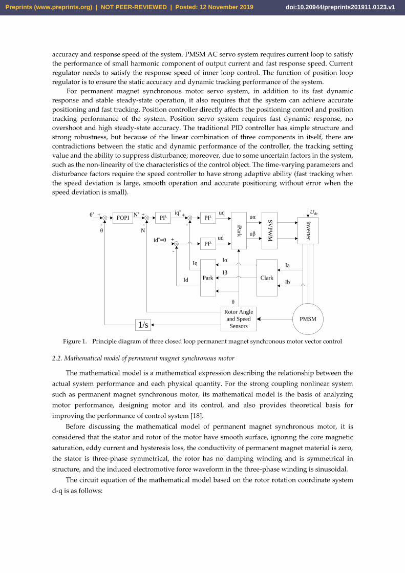
The control principle diagram of three closed-loop PMSM AC servo control system is shown in
Figure 1. The fractional PIλ regulator realizes the control of current loop and speed loop, and the
fractional PIλ controller realizes the control of position loop based on the parameter self-tuning of
fuzzy logic.
The speed loop has the ability to enhance the anti-load disturbance and robustness of the servo
system. The component of the torque and current generated by the output of the speed loop is the
given value of the current loop. The output of the current loop directly affects the drive of the
inverter to the motor, and the setting of the parameters of the current loop directly affects the control
Preprints (www.preprints.org) | NOT PEER-REVIEWED | Posted: 12 November 2019 doi:10.20944/preprints201911.0123.v1
accuracy and response speed of the system. PMSM AC servo system requires current loop to satisfy
the performance of small harmonic component of output current and fast response speed. Current
regulator needs to satisfy the response speed of inner loop control. The function of position loop
regulator is to ensure the static accuracy and dynamic tracking performance of the system.
For permanent magnet synchronous motor servo system, in addition to its fast dynamic
response and stable steady-state operation, it also requires that the system can achieve accurate
positioning and fast tracking. Position controller directly affects the positioning control and position
tracking performance of the system. Position servo system requires fast dynamic response, no
overshoot and high steady-state accuracy. The traditional PID controller has simple structure and
strong robustness, but because of the linear combination of three components in itself, there are
contradictions between the static and dynamic performance of the controller, the tracking setting
value and the ability to suppress disturbance; moreover, due to some uncertain factors in the system,
such as the non-linearity of the characteristics of the control object. The time-varying parameters and
disturbance factors require the speed controller to have strong adaptive ability (fast tracking when
the speed deviation is large, smooth operation and accurate positioning without error when the
speed deviation is small).
PIλ
PIλ
iPark
SV
PW
M
inverter
ClarkPark
Rotor Angle
and Speed
Sensors
PMSM
+ + +
+
- - -
-
uq
ud
uα
uβ
Iα
Iβ
Ia
Ib
θ
θ
Iq
Id
id*=0
iq*
N
N*θ* Udc
1/s
PIλFOPI
Figure 1. Principle diagram of three closed loop permanent magnet synchronous motor vector control
2.2. Mathematical model of permanent magnet synchronous motor
The mathematical model is a mathematical expression describing the relationship between the
actual system performance and each physical quantity. For the strong coupling nonlinear system
such as permanent magnet synchronous motor, its mathematical model is the basis of analyzing
motor performance, designing motor and its control, and also provides theoretical basis for
improving the performance of control system [18].
Before discussing the mathematical model of permanent magnet synchronous motor, it is
considered that the stator and rotor of the motor have smooth surface, ignoring the core magnetic
saturation, eddy current and hysteresis loss, the conductivity of permanent magnet material is zero,
the stator is three-phase symmetrical, the rotor has no damping winding and is symmetrical in
structure, and the induced electromotive force waveform in the three-phase winding is sinusoidal.
The circuit equation of the mathematical model based on the rotor rotation coordinate system
d-q is as follows:
Preprints (www.preprints.org) | NOT PEER-REVIEWED | Posted: 12 November 2019 doi:10.20944/preprints201911.0123.v1

q
rdr
q
dq
q
q
q
q
qr
d
q
d
d
d
d
d
Li
L
Li
L
RU
Li
dt
d
iL
Li
L
RU
Li
dt
d
01
1
(1)
Where: Ld and Lq are the main inductors on d and q axis; R is the internal resistance of stator; id
and iq are the current components on d and q axis; Ud and Uq are the voltage components on d and
q axis; ωr is the angular speed of rotor; λ0 is the electromagnetic torque coefficient.
The torque equation is as follows:
qdqdqfne iiLLipT 2
3 (2)
The equation of motion is as follows:
dt
dJTT r
Le
(3)
Among them, Te is the electromagnetic torque, TL is the motor torque, J is the moment of inertia,
pn is the pole pairs of the rotor, Ψf is the flux produced by the permanent magnet.
2.3. Vector Control of Permanent Magnet Synchronous Motor
In vector control of AC motor, in order to simulate the control of DC motor, the coordinate
transformation of AC motor is needed first, that is, from three-phase stator ABC coordinate system
of AC motor to two-phase rotor d-q coordinate system that can be controlled by DC motor, and then
the control quantity is obtained by DC motor control theory. In order to control AC motor by Inverse
Coordinate transformation, this paper adopts SVPWM method to control the three-phase power
supply of the motor.
Figure 2. Structure of space vector pulse width modulation algorithm
According to the calculation steps of SVPWM algorithm and module building method [21], the
structure diagram of space vector pulse width modulation algorithm is established as shown in
Figure 2. Sector judgment module sub1_N determines the sector where the vector is located,
adjacent action time module sub1_XYZ determines the action time of adjacent two vectors, T1 and
T2 generation module sub1_T1T2 simulates the action time ratio of adjacent vectors, vector
switching point realization module sub1_Tcm determines the switching point of the comparator,
and SVPWM waveform generation module sub1_PW M generates six PWM waves.
Preprints (www.preprints.org) | NOT PEER-REVIEWED | Posted: 12 November 2019 doi:10.20944/preprints201911.0123.v1

2.4. Fuzzy PIλ Position Control(FOPI)
Fuzzy fractional PIλ controller combines fuzzy control with fractional PIλ control. According to
the actual operation, the parameters are self-tuned online according to the rules of parameter
adjustment. The position controller consists of two parts, i. e. fractional PIλ control part and
parameter setting part of fuzzy reasoning. Its structure is shown in Figure. 3.
Fractional order
PI controller
(FOPI)
fuzzy inference
Kp Ki
de/dtObject
λrye+
-
Figure 3. Principle Diagram of Fuzzy Parameter Self-tuning FOPI Controller
3. Fuzzy Parameter Self-tuning PIλ Controller
3.1. Fractional-Order Operator
Fractional calculus is essentially a non integer order calculus, or any order calculus, the order
number can be real or even for the complex number. The basic operation of fractional calculus
ista D [22], it can be defined as
0,
0,1
0,
Rd
R
Rdt
d
D
t
a
ta
(4)
Where a and t are the upper and lower bounds of the operators, α is the order, which can be any
complex number, assuming a real number in the paper. Where R is the real part of α.
There are several famous definitions for fractional derivatives. Among them, the most
frequently used definitions are Riemann-Liouville definition and Caputo definition [22].
The fractional-order differ-integral operator satisfies the exchange law and the superposition
principle [22]
tfDtfDDtfDD (5)
3.2. Fractional-Order System
Fractional order system is the object model based on fractional differential equation. Some basic
theory of fractional differential equations is also the basis of fractional order systems. The general
form of the fractional order linear differential equation:
gDbgDbgDbfDafDafDa mn
mn011
01
0
01
(6)
Where, yxff , and yxgg , are the functions of variables X and Y, which is the output
and input respectively. The value of ia and jb are real number, ia (i= 0,1,…,n) and jb (j=
Preprints (www.preprints.org) | NOT PEER-REVIEWED | Posted: 12 November 2019 doi:10.20944/preprints201911.0123.v1

0,1,…,m) can be fractional or decimal, and meet the conditions011 nn
and
011 mm.
For zero initial conditions, the Eq. 6 for Laplace transform, the transfer function is obtained:
01
01
01
01)(
sasasa
sbsbsbsG
nn
mm
nn
mm
(7)
The fractional order system identification methods include two kinds of time domain method
and frequency domain method. In recent years, the intelligent optimization method is applied to the
identification of fractional order systems.
Oustaloup Approximation Algorithm
Oustaloup’s approximation method uses a band-pass filter to approximate the fractional-order
operator sλbased on frequency domain response. The approximate transfer function of a continuous
fractional-order operator sλwith Oustaloup Algorithm is as follows [23]:
N
Nk k
kf
s
sKsG
'
(8)
Where the zeros, poles and the gain can be evaluated, respectively, as:
12
12
1
'
N
Nk
b
hbk
(9)
12
12
1
N
Nk
b
hbk
(10)
N
Nk k
k
b
hK'
2
(11)
In our simulation, for approximation of sλ, frequency range is closed as: hb , and
001.0b , 1000h , N=4.
3.3. Fractional Order PI Controller(PIλ)
Fractional order PID controller is a generalization of traditional PID controller [17]. Differential
control is not usually used for permanent magnet synchronous motor control, so the transfer
function of PI lambda controller [20] is as follows:
)0()( s
kksG i
pc (12)
Where s = jω is complex frequency, kp is proportional constant, ki is integral constant, and λ is
real number. Consider using the fuzzy logic algorithm to adjust the parameters in (1). The
proportional coefficient kp, integral coefficient ki and integral order λ are determined by the
following items:
Ppp Ekk 10 (13)
Iii ECEkk ,10 (14)
Preprints (www.preprints.org) | NOT PEER-REVIEWED | Posted: 12 November 2019 doi:10.20944/preprints201911.0123.v1

ECE,0 (15)
Among them, {E}P,{E,EC}I,{E,EC}λ are the results of fuzzy reasoning. kp0, ki0 and λ0 are the
initial values of the parameters respectively. As for the determination of initial value, the
requirement of self-adjusting controller parameters for initial value is not high. Because of the
robustness of PID control and the flexibility of fuzzy control, conventional PID method can be used
to control the system first, without requiring that all performance indicators of the system meet the
requirements. As long as the system reaches a stable state, these parameters can be used as the initial
value of PIλ parameter adjustment. Then the PIλ parameters are fine-tuned on-line by using fuzzy
control, so that the system performance index can meet the requirements.
3.4. Design of Fuzzy Parameter Self-tuning Controller
Fuzzy parameter self-tuning PIλ controller is designed. Based on fractional order PI controller
(FOPI), the parameters kp, ki and λ of fractional order PI controller are tuned online according to the
idea of fuzzy reasoning, taking the deviation E and deviation change rate Ec of feedback value and
given value of controlled object as input, in order to meet the need of control accuracy of different
control systems. The fuzzy controller has two-input and three-output .
3.4.1. Determination of Membership Function
The determination of membership function of input and output variables is a key link. In this
paper, the input variables of the fuzzy controller are deviation E and deviation rate EC, and the
output variables are △ kp,△ki,△λ. The word sets describing input and output variables are
{negative large, negative medium, negative small, zero, positive small, positive medium, positive
large} and set their universe as {E, EC}={-3, -2, -1, 0, 1, 2, 3} and the fuzzy subset as {NB, NM, NS, ZO,
PS, PM, PB}. The fields of (-0.6,-0.4,-0.2, 0, 0.2, 0.4, 0.6}; (-0.06,-0.04,-0.02, 0.02, 0.04, 0.06}; (-0.3,-0.2,-0.1,
0.1, 0.2, 0.3} of (△ kp); and (-0.06} of (-0.3,-0.2,-0.1, 0.1, 0.2, 0.3} of (-0.6) of (-0.04,-0.04,-0.06) of (- The
membership function is Gauss membership function with overlapping symmetric distribution. The
membership curves of input and output variables are shown in Figure 4.
(a)
(b)
Figure 4. Membership Curve of Input and Output Variables.
(a) Membership Curves of E and EC; (b) .Membership Curves of △ kp
3.4.2. Parameter Tuning Rule of PIλ Controller
According to the real-time deviation E and the deviation change rate EC of the system,
according to the experience, according to the setting principle and adjustment test, the rules are set
in the fuzzy logic toolbox, and 49 control rules are obtained. The rule surface diagrams of the output
and input variables are shown in Figure 5.
• 1. (e==NB) & (ec==NB) => (delta-kp=PB)(delta-ki=NB)(delta-lamda=NB) (1)
• 2. (e==NB) & (ec==NM) => (delta-kp=PB)(delta-ki=NB)(delta-lamda=NB) (1)
• 3. (e==NB) & (ec==NS) => (delta-kp=PM)(delta-ki=NB)(delta-lamda=NB) (1)
Preprints (www.preprints.org) | NOT PEER-REVIEWED | Posted: 12 November 2019 doi:10.20944/preprints201911.0123.v1

• 4. (e==NB) & (ec==ZO) => (delta-kp=PM)(delta-ki=NM)(delta-lamda=NM) (1)
• 5. (e==NB) & (ec==PS) => (delta-kp=PS)(delta-ki=NM)(delta-lamda=NM) (1)
• 6. (e==NB) & (ec==PM) => (delta-kp=PS)(delta-ki=ZO)(delta-lamda=ZO) (1)
• 7. (e==NB) & (ec==PB) => (delta-kp=ZO)(delta-ki=ZO)(delta-lamda=ZO) (1)
• ............
• 43. (e==PB) & (ec==NB) => (delta-kp=ZO)(delta-ki=ZO)(delta-lamda=ZO) (1)
• 44. (e==PB) & (ec==NM) => (delta-kp=NS)(delta-ki=ZO)(delta-lamda=ZO) (1)
• 45. (e==PB) & (ec==NS) => (delta-kp=NS)(delta-ki=PS)(delta-lamda=PS) (1)
• 46. (e==PB) & (ec==ZO) => (delta-kp=NM)(delta-ki=PM)(delta-lamda=PM) (1)
• 47. (e==PB) & (ec==PS) => (delta-kp=NM)(delta-ki=PB)(delta-lamda=PB) (1)
• 48. (e==PB) & (ec==PM) => (delta-kp=NB)(delta-ki=PB)(delta-lamda=PB) (1)
• 49. (e==PB) & (ec==PB) => (delta-kp=NB)(delta-ki=PB)(delta-lamda=PB) (1)
All figures and tables should be cited in the main text as Figure 1, Table 1, etc.
(a)
(b)
Figure 5. Rule Surface Map of Output Variables
4. Simulation Research and Result Analysis
4.1 Three-Closed-Loop PMSM Simulation Model
Using the Permanent Magnet Synchronous Motor (PMSM) module of Simulink/SimPowerSystem/
Machines sublibrary, the simulation model of the system is established. The motor parameters are shown in
Table 1.
Tab.1 Parameters of permanent magnet synchronous motor
Parameter name (unit) Value
stator resistance R() 0.975
Stator inductance Ld、Lq(H) 0.0085
Flux of Permanent Magnet Rotor in Stator Loop (Wb) 0.175
Rotating inertia of rotor and load J(2mkg ) 0.00008
Viscous friction coefficient F( smN ) 4.047e-4
Pole logarithm of motor p 4
The simulation model of three closed-loop permanent magnet synchronous motor in Simulink is
established as shown in Figure 6. The simulation system consists of position regulator, speed regulator,
current regulator, Park inverse conversion module, inverter module, SVPWM module, permanent magnet
synchronous motor, parameter measurement module, Clark conversion module and Park conversion module.
The system adopts three closed-loop control mode of position, speed and current. Both internal control
loops adopt digital PI controller, and the outer control loop is position loop. Two different controllers,
digital PI and Fuzzy Adaptive Fractional PI lambda, are used as position regulators for simulation.
Preprints (www.preprints.org) | NOT PEER-REVIEWED | Posted: 12 November 2019 doi:10.20944/preprints201911.0123.v1

Figure 6 Simulation block diagram of AC servo system
4.2 Simulation of current loop and velocity loop
Through the simulation of current loop and speed loop, the simulation waveform of AC servo system
is obtained as shown in Figure 4. The given speed is 1000 rad / s, no-load operation, and the simulation
time is 0.05s.
(a) Speed waveform
(b) Torque waveform
(c) iq waveform
(c) id waveform
Figure 7. Simulation results of AC servo system
(a) Speed waveform; (b) Torque waveform; (c). iq waveform; (d) id waveform
Figure 4 (a) shows the speed waveform. It can be seen that the maximum speed of the system reaches
1100 rad, the overshoot is 10%, and the adjustment time is 0.026 s (± 2% error band). The system can
follow the given speed better, which indicates that the system has good follow performance. Figure 4 (b)
shows the torque waveform. It can be seen that in the early stage of motor starting, the torque fluctuates
greatly, the maximum torque reaches 27 N·m, and the later stage is basically stable. Figure 4 (c) and (d) are
the waveforms of IQ and ID respectively. The waveforms of [0.085, 0.09] interval are intercepted, which
Preprints (www.preprints.org) | NOT PEER-REVIEWED | Posted: 12 November 2019 doi:10.20944/preprints201911.0123.v1

are consistent with the results of theoretical analysis. It can be seen that the simulation model of servo AC
system is basically realized, and the established model can truly reflect the characteristics of the system.
4.3 Position PI Control
The position loop, current loop and speed loop are all controlled by PI, and the parameters are shown
in Table 2.
Tab.2 Parameters of the system regulator
Regulator Proportional P Integral I
Location loop 100 5
Speed loop 0.1 16
Id current loop 30 1900
iqcurrent loop 30 1900
4.4 Fuzzy Fractional PI Control
The position loop is replaced by a fractional PI parameter self-tuning controller based on fuzzy logic.
The subsystem is shown in Figure 8. The fuzzy controller is designed with Fuzzy Logic Toolbox. The
initial parameters of the fractional PI controller are kp0=100, ki0=5, and lambda=0.8. The input -output
proportional coefficients of the fuzzy controller are 1, 2 and 10, respectively.
Figure8 Simulation Model of Fuzzy PIλ
Controller
The traditional PI control strategy and the fuzzy fractional PI control strategy are used to simulate the
three closed-loop control system of PMSM. The sinusoidal input with 10 rad/s amplitude and 10 rad/s
frequency is selected as the given trajectory. The simulation time is 1.5 s, and the simulation algorithm uses
ode23tb. First, the system starts without load and runs with 0.5s load (5N.m).
The results of the two control strategies are shown in Figure 9. Figure (a) is position tracking, figure
(b) is velocity tracking, figure (c) is trajectory error, and figure (d) is velocity error. It can be seen from
figure (a) that the trajectory of the motor achieves the tracking of the input signal, and the error curve is
shown in figure (c). The traditional PI controller is used as the position loop regulator in the simulation
experiment. The position tracking process has certain fluctuation, the rising time is longer and the
regulating time is longer. After the sudden load disturbance, the position response fluctuation is larger, the
recovery time is longer, the speed fluctuates greatly in a short time, and the speed deviation is larger in the
start-up process.
It can be seen that the trajectory tracking error is small by using the fuzzy PI_ lambda controller, and it
has stronger robustness to load disturbance and better speed response in steady state.
Preprints (www.preprints.org) | NOT PEER-REVIEWED | Posted: 12 November 2019 doi:10.20944/preprints201911.0123.v1

(a)
(b)
(a)
(b)
Figure 9 Simulation results of fuzzy PIλ
position Controller
4.5 Compound Control with Speed Feed-forward and Acceleration Feed-forward
Generally, the random signal of system response is composed of step, constant velocity and sinusoidal
signal. When the system is moving on a constant velocity slope, there will be a large tracking error. At this
time, speed feed-forward signal should be added to implement the composite control of adaptive fuzzy PI
lambda and feed-forward compensation [21]:
csq vkuu *1 (16)
In the formula: vc is a velocity value generated by differential position command signal,
Tnxnxv ggc 1 ,T is the sampling period, n is the current moment, and ksq is the velocity
feed-forward gain.。
When the system moves sinusoidally, because the input signal is a second-order signal, only adding
speed feed-forward compensation can not achieve good tracking effect. Therefore, acceleration
feed-forward signal should be added to compensate the system, and the composite control of adaptive fuzzy
PIλ, speed feed-forward and acceleration feed-forward is implemented.
aaqcsq vkvkuu **1 (17)
Among:kaq is the acceleration feed-forward gain, and va is the acceleration value differentiated by the
velocity signal, Tnvnvv cca 1 .
The simulation model of the compound control of fuzzy PIλ and feed-forward compensation is
established as shown in Figure 10.
Preprints (www.preprints.org) | NOT PEER-REVIEWED | Posted: 12 November 2019 doi:10.20944/preprints201911.0123.v1

Figure 10 Compound Control Model of Fuzzy PI
λ and Feed-forward Compensation
4.6 Performance Analysis of Three Position Control Strategies
The step signal is used as the input signal. Given the position of 100, the simulation time is chosen to
be 0-1s, and the load moment of 10N.M is suddenly applied to the system when the simulation time is 0.5s.
The step response curves of servo system position control under three kinds of controllers are shown in
figure 11. According to the data obtained from each curve, the performance comparison of the three control
modes is calculated and listed as shown in Table 3.
Figure 11 Step Response Curves of Three Control Strategies
Tab.3 Performance comparison table of three position controllers
Position regulator Rise time/s Overshoot/% Settling time/s
PI controller 0.0450 0.15 0.051
Fuzzy PIλ
Compound Controller 0.0452 0 0.053
Compound Controller with
Feed-forward Compensation
0.0445 0 0.050
The simulation results show that the three control strategies can reach the set value, PI control has
0.15% overshoot, and the fuzzy PI controller and composite control have no overshoot. From the time
analysis, the rise time and adjustment time of the composite control are 0.0445 and 0.05, respectively,
which are smaller than the response time of the other two methods. Considering the comprehensive
Preprints (www.preprints.org) | NOT PEER-REVIEWED | Posted: 12 November 2019 doi:10.20944/preprints201911.0123.v1

performance, the effect of compound control is the best.
5. Conclusion
The application of fuzzy PIλ
control in permanent magnet synchronous motor servo system is studied.
The disadvantages of traditional PID control and the disadvantages of variable parameters, non-linearity,
time delay and time variation of servo system are overcome by using the characteristics of fuzzy control
such as non-linearity, variable structure, self-adaptation, self-tuning and strong robustness. Fuzzy parameter
self-tuning fractional-order PI controller, simulation results show that the control effect is better than the
traditional PID control, and the desired system control effect can be obtained. After adding feed -forward
compensation, the response speed is accelerated, the overshoot is small, and the parameters of the PID
controller can be adjusted online and real-time according to the changes of the controlled object, which can
reduce the system error; moreover, the system has strong robustness and is not susceptible to external
interference and changes in system parameters. It can be seen that for AC servo system with non-linearity
and time-varying parameters, the compound position control with fuzzy PIλ
and feed-forward
compensation can meet the requirements of system control and improve the dynamic and static
characteristics of the system.
Author Contributions: C.Z. and L.W. conceived of and designed the method. C.X. analyzed the data; C.Z.
and L.W. established the model, validate the model by experiments and wrote the paper.
Funding: The work in this paper is supported by National Key R&D Program of China (Grant No.
2018YFB1700100, 2018YFB1700204)), and Science and Technology Funds from Liaoning Province
Education Department (Grant No. JDL2017004)
Conflicts of Interest: The authors declare no conflict of interest.
References
1. XUE Wei, LI Yongli, CANG Shijian, et al. Chaotic behavior and circuit implementation of a
fractional-order permanent magnet synchronous motor model[J]. Journal of the Franklin Institute, 2015,
352(7):2887-2898.
2. Thakar U , Joshi V , Vyawahare V . Design of fractional -order PI controllers and comparative analysis of
these controllers with linearized, nonlinear integer-order and nonlinear fractional-order representations of
PMSM[J]. International Journal of Dynamics & Control, 2017, 5(1):187-197.
3. BAO Xiping, JI Zhi, ZHU Tao. Research and Development on High-performance PMSM Servo System [J].
Micromotors, 2014,47(7): 84 -88.
4. LIU Chunqiang, LUO Guangzhao, TU Wencong,et al. Servo systems With double closed-loops based on
active disturbance rejection controllers[J]. Proceedings of the CSEE,2017,37(23):7032-7039.
5. ZUO Yuefei,ZHANG Jie, LIU Chang,et al. Integrated Design for Permanent Magnet Synchronous
Motor Servo Systems Based on Active Disturbance Rejection Control[J]. Transactions of China
Electrotechnical Society, 2016, 31(11):51-58.
6. HOU Runmin, LIU Rongzhong, HOU Yuanlong, et al. Application of adaptive fuzzy wavelet neural
sliding mode control in AC servo system[J]. Acta Armamentarii, 2014,35 (6):769-775
7. HOU Runmin, LIU Rongzhong, GAO Qiang, et al. Application of adaptive fuzzy wavelet neural network
in AC servo control system[J]. Acta Armamentarii, 2015, 36(5):781-788.
8. ZHANG Beibei, ZHAO Dongya, ZHAO Tong. Adaptive sliding mode control based on disturbance
observer for manipulator systems [J]. Information and Control, 2018,47(2):184-190.
9. ZHANG Bitao, PI Youguo, LUO Ying. Fractional order sliding-mode control based on parameters
auto-tuning for velocity control of permanent magnet synchronous motor[J]. Isa Transactions, 2012,
51(5):649-656.
Preprints (www.preprints.org) | NOT PEER-REVIEWED | Posted: 12 November 2019 doi:10.20944/preprints201911.0123.v1

10. SUN Guanghui , MA Zhiqiang . Practical Tracking Control of Linear Motor With Adaptive Fractional
Order Terminal Sliding Mode Control[J]. IEEE/ASME Transactions on Mechatronics, 2017,
22(6):2643-2653.
11. YUE Yaobin, ZHANG Ruikun, WU Bing, et al. Direct torque control method of PMSM based on fractional
order PID controller[C]// Data Driven Control & Learning Systems. 2017,5.
12. Xie Y , Tang X , Song B , et al. Data-driven adaptive fractional order PI control for PMSM servo system
with measurement noise and data dropouts[J]. ISA Transactions, ISA Transactions Volume 75, April 2018,
Pages 172-188.
13. Delavari H, Ghaderi R,Ranjbar A, et al. Fuzzy fractional order sliding mode controller for nonlinear
systems[J]. Communications in Nonlinear Science and Numerical Simulation, 2010,15(4):963-978.
14. Lin T.C.; Kuo C.H. H∞ synchronization of uncertain fractional order chaotic systems: Adaptive fuzzy
approach [J]. ISA Transactiona, 2012,50(4):548-556.
15. Aghababa M.P.; Comments on “H∞ synchronization of uncertain fractional order chaotic systems:
Adaptive fuzzy approach”[J]. ISA Transactiona,, 2012, 51(1):11-12.
16. Zhong Q.S.; Bao J.F.; Yu Y.B.; et al. Impulsive control for fractional-order chaotic systems[J]. Chinese
Physics Letters, 2008, 25(8):2812-2815.
17. WANG Lin, ZHONG Chongquan, Design of Optimal Fractional-Order PID Controllers Using Particle
Swarm Optimization Algorithm for DC Motor System[J], Advanced Information Technology, Electronic &
Automation Control Conference, 2015. 175-179.
18. YUAN Lei, HU Bingxin, WEI Keyin, etc. The Control Principle and MATLAB Simulation of Modern
Permanent Magnet Synchronous Motor[M]. Beijing: Beijing Aerospace University Press, 2016:27-51.
19. YUAN Dengke, XU Yandong, LI Xiutao. Variable Frequency Speed Regulating System of Permanent
Magnet Synchronous Motor and its Control[M]. Beijing: Machinery Industry Press, 2016:55-60.
20. H. Ramezanian, S. Balochian and A. Zare. Design of optimal fractional-order PID controllers using particle
swarm optimization algorithm for Automatic voltage regulator(AVR) system[J]. Journal of Control,
Automation and Electrical Systems, 2013, 24: 601-611.
21. ZHANG Ying, XIA Xuewen, LI Fazhong et al. An Adaptive Fuzzy Sliding Mode Position Controller for
Naval Gun Servo System[J]. Acta Armamentarii, 2015.36(S2):67-72.
22. Petras I: Fractional order nonlinear systems-modeling, analysis and simulation. New York, Springer
publication, 2011.
23. H. Ramezanian, S. Balochian and A. Zare, “Design of optimal fractional-order PID controllers using
particle swarm optimization algorithm for Automatic voltage regulator(AVR) system,” J Control Autom
Electr Syst, vol. 24, pp. 601-611, 2013.
Preprints (www.preprints.org) | NOT PEER-REVIEWED | Posted: 12 November 2019 doi:10.20944/preprints201911.0123.v1