ARTICLE 310: CONDUCTORS FOR GENERAL WIRING NEC TABLE … · 220 260 300 350 405 455 500 570 615 700...
14
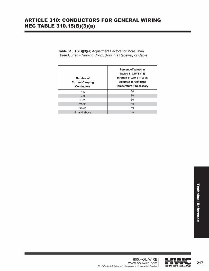
Technical Reference 217 800.HOU.WIRE www.houwire.com 2012 Product Catalog. All data subject to change without notice. Table 310.15(B)(3)(a) Adjustment Factors for More Than Three Current-Carrying Conductors in a Raceway or Cable ARTICLE 310: CONDUCTORS FOR GENERAL WIRING NEC TABLE 310.15(B)(3)(a) Percent of Values in Tables 310.15(B)(16) through 310.19(B)(19) as Adjusted for Ambient Temperature if Necessary 80 70 50 45 40 35 Number of Current-Carrying Conductors 4-6 7-9 10-20 21-30 31-40 41 and above
Transcript of ARTICLE 310: CONDUCTORS FOR GENERAL WIRING NEC TABLE … · 220 260 300 350 405 455 500 570 615 700...
Technical Reference
217800.HOU.WIRE
www.houwire.com2012 Product Catalog. All data subject to change without notice.
Table 310.15(B)(3)(a) Adjustment Factors for More Than Three Current-Carrying Conductors in a Raceway or Cable
ARTICLE 310: CONDUCTORS FOR GENERAL WIRINGNEC TABLE 310.15(B)(3)(a)
Percent of Values inTables 310.15(B)(16)
through 310.19(B)(19) as Adjusted for Ambient
Temperature if Necessary
807050454035
Number of Current-Carrying
Conductors
4-67-9
10-2021-3031-40
41 and above
Tech
nica
l Ref
eren
ce
218800.HOU.WIREwww.houwire.com2012 Product Catalog. All data subject to change without notice.
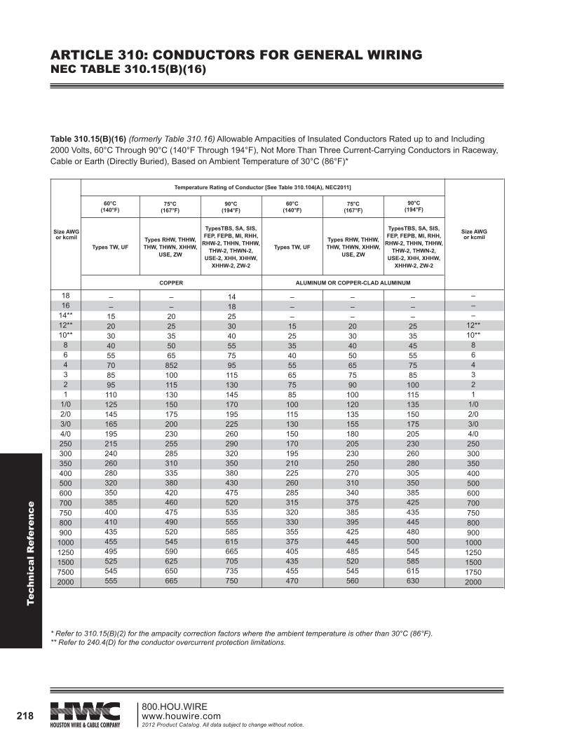
ARTICLE 310: CONDUCTORS FOR GENERAL WIRINGNEC TABLE 310.15(B)(16)
Table 310.15(B)(16) (formerly Table 310.16) Allowable Ampacities of Insulated Conductors Rated up to and Including 2000 Volts, 60°C Through 90°C (140°F Through 194°F), Not More Than Three Current-Carrying Conductors in Raceway, Cable or Earth (Directly Buried), Based on Ambient Temperature of 30°C (86°F)*
* Refer to 310.15(B)(2) for the ampacity correction factors where the ambient temperature is other than 30°C (86°F).** Refer to 240.4(D) for the conductor overcurrent protection limitations.
Size AWG or kcmil
Size AWG or kcmil
60°C(140°F)
Types TW, UF Types TW, UFTypes RHW, THHW, THW, THWN, XHHW,
USE, ZW
Types RHW, THHW, THW, THWN, XHHW,
USE, ZW
TypesTBS, SA, SIS, FEP, FEPB, MI, RHH,
RHW-2, THHN, THHW, THW-2, THWN-2,
USE-2, XHH, XHHW, XHHW-2, ZW-2
TypesTBS, SA, SIS, FEP, FEPB, MI, RHH,
RHW-2, THHN, THHW, THW-2, THWN-2,
USE-2, XHH, XHHW, XHHW-2, ZW-2
60°C(140°F)
75°C(167°F)
75°C(167°F)
90°C(194°F)
90°C(194°F)
COPPER ALUMINUM OR COPPER-CLAD ALUMINUM
Temperature Rating of Conductor [See Table 310.104(A), NEC2011]
––
1520304055708595110125145165195215240260280320350385400410435455495525545555
––
2025355065
852100115130150175200230255285310335380420460475490520545590625650665
1418253040557595115130145170195225260290320350380430475520535555585615665705735750
–––
1525354055657585
100115130150170195210225260285315320330355375405435455470
–––
20304050657590
100120135155180205230250270310340375385395425445485520545560
–––
253545557585
100115135150175205230260280305350385425435445480500545585615630
–––
12**10**
864321
1/02/03/04/0250300350400500600700750800900
10001250150017502000
1816
14**12**10**
864321
1/02/03/04/0250300350400500600700750800900
10001250150075002000
Technical Reference
219800.HOU.WIRE
www.houwire.com2012 Product Catalog. All data subject to change without notice.
ARTICLE 310: CONDUCTORS FOR GENERAL WIRINGNEC TABLE 310.15(B)(17)
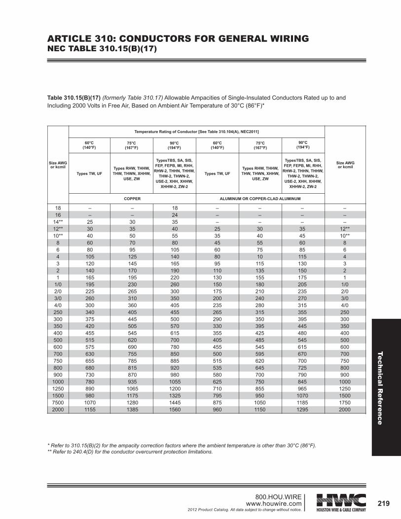
Table 310.15(B)(17) (formerly Table 310.17) Allowable Ampacities of Single-Insulated Conductors Rated up to and Including 2000 Volts in Free Air, Based on Ambient Air Temperature of 30°C (86°F)*
* Refer to 310.15(B)(2) for the ampacity correction factors where the ambient temperature is other than 30°C (86°F).** Refer to 240.4(D) for the conductor overcurrent protection limitations.
––
2530406080
105120140165195225260300340375420455515575630655680730780890980
10701155
––
3035507095
125145170195230265310360405445505545620690755785815870935
1065117512801385
182435405580
105140165190220260300350405455500570615700780850885920980
10551200132514451560
–––
253545608095110130150175200235265290330355405455500515535580625710795875960
–––
3040557510115135155180210240280315350395425485545595620645700750855950
10501150
–––
35456085115130150175205235270315355395445480545615670700725790845965
107011851295
–––
12**10**
864321
1/02/03/04/0250300350400500600700750800900
10001250150017502000
Size AWG or kcmil
60°C(140°F)
Types TW, UF Types TW, UFTypes RHW, THHW, THW, THWN, XHHW,
USE, ZW
Types RHW, THHW, THW, THWN, XHHW,
USE, ZW
TypesTBS, SA, SIS, FEP, FEPB, MI, RHH,
RHW-2, THHN, THHW, THW-2, THWN-2,
USE-2, XHH, XHHW, XHHW-2, ZW-2
TypesTBS, SA, SIS, FEP, FEPB, MI, RHH,
RHW-2, THHN, THHW, THW-2, THWN-2,
USE-2, XHH, XHHW, XHHW-2, ZW-2
60°C(140°F)
75°C(167°F)
75°C(167°F)
90°C(194°F)
90°C(194°F)
COPPER ALUMINUM OR COPPER-CLAD ALUMINUM
Temperature Rating of Conductor [See Table 310.104(A), NEC2011]
Size AWG or kcmil
1816
14**12**10**
864321
1/02/03/04/0250300350400500600700750800900
10001250150075002000
Tech
nica
l Ref
eren
ce
220800.HOU.WIREwww.houwire.com2012 Product Catalog. All data subject to change without notice.
ARTICLE 310: CONDUCTORS FOR GENERAL WIRINGNEC TABLE 310.15(B)(18)
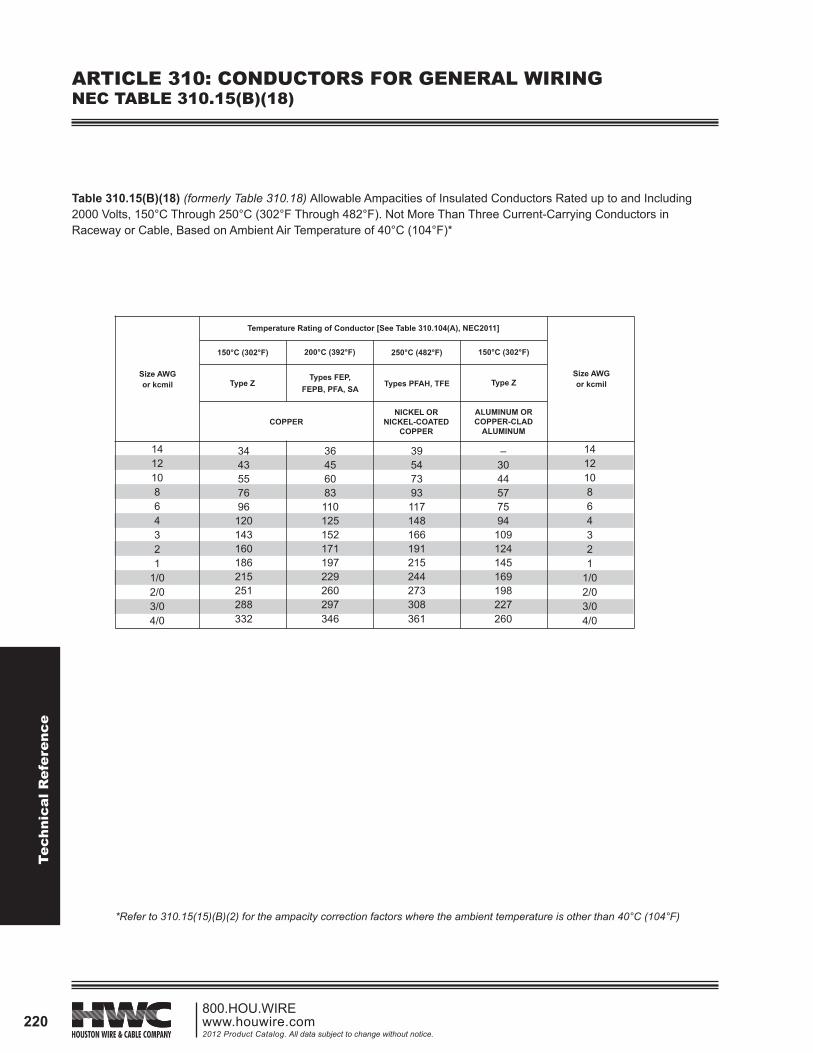
Table 310.15(B)(18) (formerly Table 310.18) Allowable Ampacities of Insulated Conductors Rated up to and Including 2000 Volts, 150°C Through 250°C (302°F Through 482°F). Not More Than Three Current-Carrying Conductors in Raceway or Cable, Based on Ambient Air Temperature of 40°C (104°F)*
141210864321
1/02/03/04/0
3443557696
120143160186215251288332
36456083110125152171197229260297346
39547393117148166191215244273308361
–3044577594
109124145169198227260
141210864321
1/02/03/04/0
250°C (482°F)150°C (302°F) 150°C (302°F)200°C (392°F)
Type ZTypes FEP,
FEPB, PFA, SATypes PFAH, TFE Type Z
Temperature Rating of Conductor [See Table 310.104(A), NEC2011]
COPPERNICKEL OR
NICKEL-COATED COPPER
ALUMINUM OR COPPER-CLAD
ALUMINUM
*Refer to 310.15(15)(B)(2) for the ampacity correction factors where the ambient temperature is other than 40°C (104°F)
Size AWG or kcmil
Size AWG or kcmil
Technical Reference
221800.HOU.WIRE
www.houwire.com2012 Product Catalog. All data subject to change without notice.
ARTICLE 310: CONDUCTORS FOR GENERAL WIRINGNEC TABLE 310.15(B)(19)
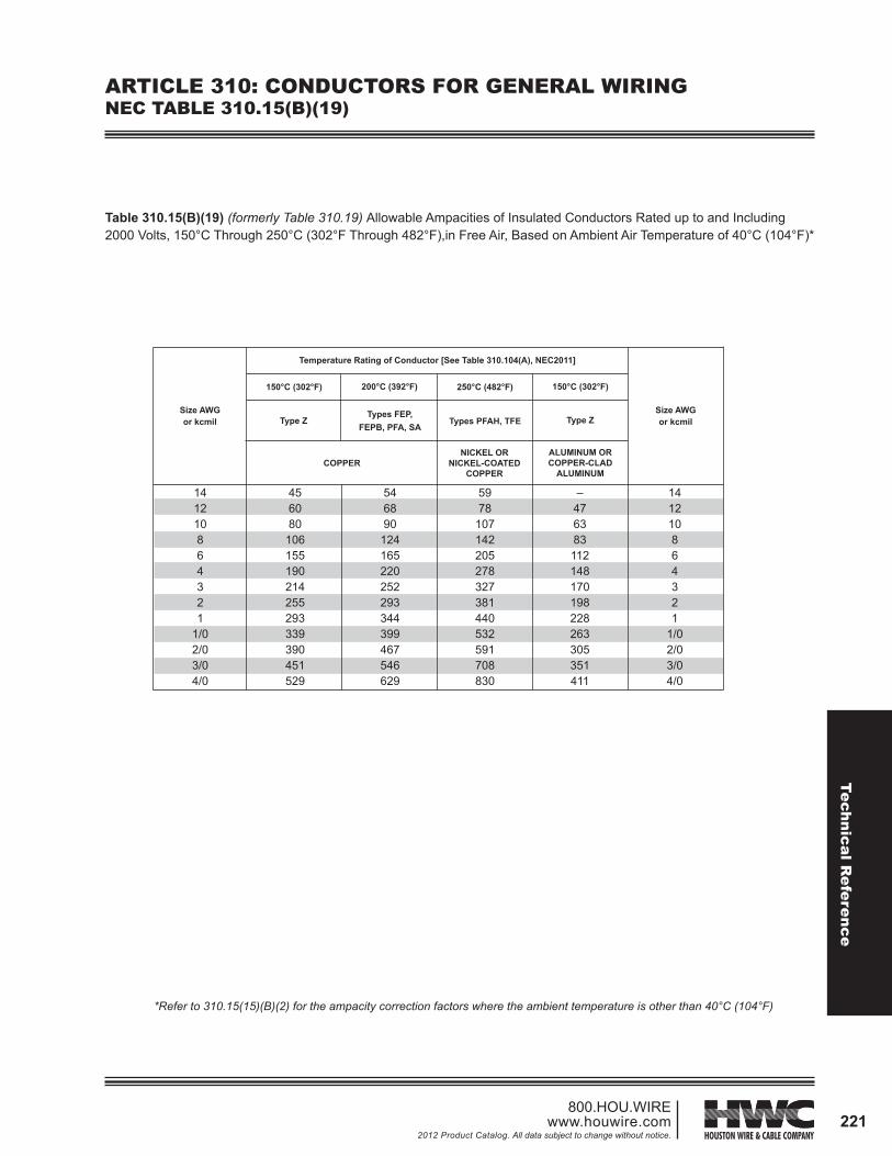
Table 310.15(B)(19) (formerly Table 310.19) Allowable Ampacities of Insulated Conductors Rated up to and Including 2000 Volts, 150°C Through 250°C (302°F Through 482°F),in Free Air, Based on Ambient Air Temperature of 40°C (104°F)*
*Refer to 310.15(15)(B)(2) for the ampacity correction factors where the ambient temperature is other than 40°C (104°F)
141210864321
1/02/03/04/0
456080
106155190214255293339390451529
546890
124165220252293344399467546629
5978
107142205278327381440532591708830
–476383112148170198228263305351411
141210864321
1/02/03/04/0
250°C (482°F)150°C (302°F) 150°C (302°F)200°C (392°F)
Size AWG or kcmil
Size AWG or kcmilType Z
Types FEP, FEPB, PFA, SA
Types PFAH, TFE Type Z
Temperature Rating of Conductor [See Table 310.104(A), NEC2011]
COPPERNICKEL OR
NICKEL-COATED COPPER
ALUMINUM OR COPPER-CLAD
ALUMINUM

Tech
nica
l Ref
eren
ce
222800.HOU.WIREwww.houwire.com2012 Product Catalog. All data subject to change without notice.
ARTICLE 310: CONDUCTORS FOR GENERAL WIRINGNEC TABLE 310.15(B)(20)
Table 310.15(B)(20) (formerly Table 310.20) Ampacities of Not More Than Three Single Insulated Conductors Rated up to and Including 2000 Volts, Supported on a Messenger, Based on Ambient Air Temperature of 40°C (104°F)*
*Refer to 310.15(15)(B)(2) for the ampacity correction factors where the ambient temperature is other than 40°C (104°F)
864321
1/02/03/04/0250300350400500600700750800900
1000
5776
101118135158183212245287320359397430496553610638660704748
6689117138158185214247287335374419464503580647714747773826879
44597892
106123143165192224251282312339392440488512532572612
516991
107123144167193224262292328364395458514570598622669716
864321
1/02/03/04/0250300350400500600700750800900
1000
250°C (482°F)150°C (302°F) 150°C (302°F)200°C (392°F)
Type ZTypes FEP,
FEPB, PFA, SATypes PFAH, TFE Type Z
Temperature Rating of Conductor [See Table 310.104(A), NEC2011]
Size AWG or kcmil
Size AWG or kcmil
COPPERNICKEL OR
NICKEL-COATED COPPER
ALUMINUM OR COPPER-CLAD
ALUMINUM
Technical Reference
223800.HOU.WIRE
www.houwire.com2012 Product Catalog. All data subject to change without notice.
ARTICLE 310: CONDUCTORS FOR GENERAL WIRINGNEC TABLE 310.21
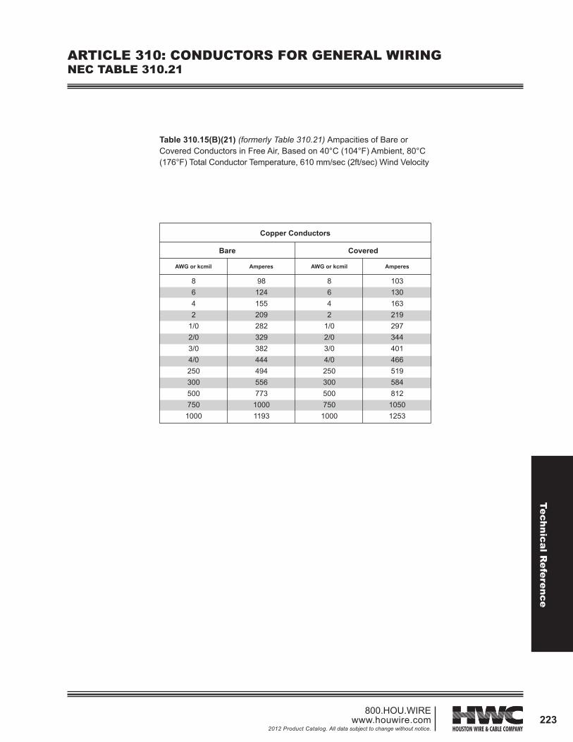
Table 310.15(B)(21) (formerly Table 310.21) Ampacities of Bare or Covered Conductors in Free Air, Based on 40°C (104°F) Ambient, 80°C (176°F) Total Conductor Temperature, 610 mm/sec (2ft/sec) Wind Velocity
8642
1/02/03/04/0250300500750
1000
98124155209282329382444494556773
10001193
8642
1/02/03/04/0250300500750
1000
103130163219297344401466519584812
10501253
Copper Conductors
Bare Covered
AWG or kcmil Amperes AWG or kcmil Amperes
Tech
nica
l Ref
eren
ce
224800.HOU.WIREwww.houwire.com2012 Product Catalog. All data subject to change without notice.
ARTICLE 310: CONDUCTORS FOR GENERAL WIRINGNEC FIGURE 310.60
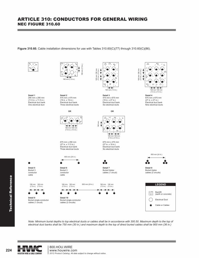
Figure 310.60. Cable installation dimensions for use with Tables 310.60(C)(77) through 310.60(C)(86).
Detail 1290 mm x 290 mm(11.5 in. x 11.5 in.)Electrical duct bankOne electrical duct
Detail 2475 mm x 475 mm(19 in. x 19 in.)Electrical duct bankThree electrical ducts
OR
Detail 4675 mm x 675 mm(27 in. x 27 in.)Electrical duct bankNine electrical ducts
Detail 3475 mm x 675 mm(19 in. x 27 in.)Electrical duct bankSix electrical ducts
OR
190 mm (7.5 in.) 190 mm 190 mm(7.5 in.) (7.5 in.)
190 mm (7.5 in.)
190
mm
(7.5
in.)
190
mm
190
mm
(7.5
in.)
(7.5
in.)
190
mm
190
mm
(7.5
in.)
(7.5
in.)
675 mm x 290 mm(27 in. x 11.5 in.)Electrical duct bankThree electrical ducts
675 mm x 475 mm(27 in. x 19 in.)Electrical duct bankSix electrical ducts
Detail 5Buried 3conductorcable
Detail 6Buried 3conductorcable
600 mm (24 in.)
Detail 7Buried triplex cables (1 circuit)
Detail 8Buried triplex cables (2 circuits)
Detail 9Buried single-conductorcables (1 circuit)
600 mm (24 in.)
Detail 10Buried single-conductorcables (2 circuits)
190 mm (7.5 in.)
190 mm(7.5 in.)
190
mm
190 mm 190 mm(7.5 in.) (7.5 in.)
600 mm (24 in.)
190 mm 190 mm(7.5 in.) (7.5 in.)
190 mm 190 mm(7.5 in.) (7.5 in.)
190 mm 190 mm(7.5 in.) (7.5 in.)
LEGEND
Backfill (earth or concrete)
Electrical Duct
Cable or Cables
Note: Minimum burial depths to top electrical ducts or cables shall be in accordance with 300.50. Maximum depth to the top of electrical duct banks shall be 750 mm (30 in.) and maximum depth to the top of direct buried cables shall be 900 mm (36 in.)

Technical Reference
225800.HOU.WIRE
www.houwire.com2012 Product Catalog. All data subject to change without notice.
1 100 Percent Insulation Level. Cables in this category shall be permitted to be applied where the system is provided with relay protection such that ground faults will be cleared as rapidly as possible but, in any case, within 1 minute. While these cables are applicable to the great majority of cable installations that are on grounded systems, they shall be permitted to be used also on other systems for which the application of cables is acceptable, provided the above clearing requirements are met in completely de-energizing the faulted section.2 133 Percent Insulation Level. This insulation level corresponds to that formerly designated for ungrounded systems. Cables in this category shall be permitted to be applied in situations where the clearing time requirements of the 100 percent level category cannot be met and yet there is adequate assurance that the faulted section will be de-energized in a time not exceeding 1 hour. Also, they shall be permitted to be used where additional insulation strength over the 100 percent level category is desirable.3 173 Percent Insulation Level. Cables in this category shall be permitted to be applied under all of the following conditions: (1) In industrial establishments where the conditions of maintenance and supervision ensure that only qualifed persons service the installation (2) Where the fault clearing time requirements of the 133 percent level category cannot be met (3) Where an orderly shutdown is essential to protect equipment and personnel (4) There is adequate assurance that the faulted section willbe de-energized in an orderly shutdown Also, cables with this insulation thickness shall be permitted to be used in 100 or 133 percent insulation level applications where additional insulation strength is desirable.
ARTICLE 310: CONDUCTORS FOR GENERAL WIRINGNEC TABLE 310.104(E)
Table 310.104(E). Thickness of Insulation for Shielded Solid Dielectric Insulated Conductors Rated 2001 to 35,000 Volts.
2,001-5,000 Volts 5,001-8,000 Volts
25,001-28,000 Volts 28,001-35,000 Volts
8,001-15,000 Volts 15,001-25,000 Volts
Conductor Size (AWG or kcmil)
100 Percent
InsulationLevel1
100 Percent
InsulationLevel1
133 Percent
InsulationLevel2
173 Percent
InsulationLevel3
100 Percent
InsulationLevel1
133 Percent
InsulationLevel2
173 Percent
InsulationLevel3
100 Percent
InsulationLevel1
133 Percent
InsulationLevel2
173 Percent
InsulationLevel3
mm
2.29
2.29
2.29
2.29
2.29
mils
90
90
90
90
90
mm
–
2.92
2.92
2.92
2.92
mils
–
115
115
115
115
mm
–
3.56
3.56
3.56
3.56
mils
–
140
140
140
140
mm
–
4.45
4.45
4.45
4.45
mils
–
175
175
175
175
mm
–
–
4.45
4.45
4.45
mils
–
–
175
175
175
mm
–
–
5.59
5.59
5.59
mils
–
–
220
220
220
mm
–
–
6.60
6.60
6.60
mils
–
–
260
260
260
mm
–
–
–
6.60
6.60
mils
–
–
–
260
260
mm
–
–
–
8.13
8.13
mils
–
–
–
320
320
mm
–
–
–
mils
–
–
–
420
420
8
6-4
2
1
1/0-2000
10.67
10.67
Conductor Size (AWG or kcmil)
100 Percent
InsulationLevel1
133 Percent
InsulationLevel2
173 Percent
InsulationLevel3
100 Percent
InsulationLevel1
133 Percent
InsulationLevel2
173 Percent
InsulationLevel3
mm
7.11
7.11
mils
280
280
mm
8.76
8.76
mils
345
345
mm
11.30
11.30
mils
445
445
mm
–
8.76
mils
–
345
mm
–
10.67
mils
–
420
mm
–
14.73
mils
–
580
1
1/0-2000
Tech
nica
l Ref
eren
ce
226800.HOU.WIREwww.houwire.com2012 Product Catalog. All data subject to change without notice.
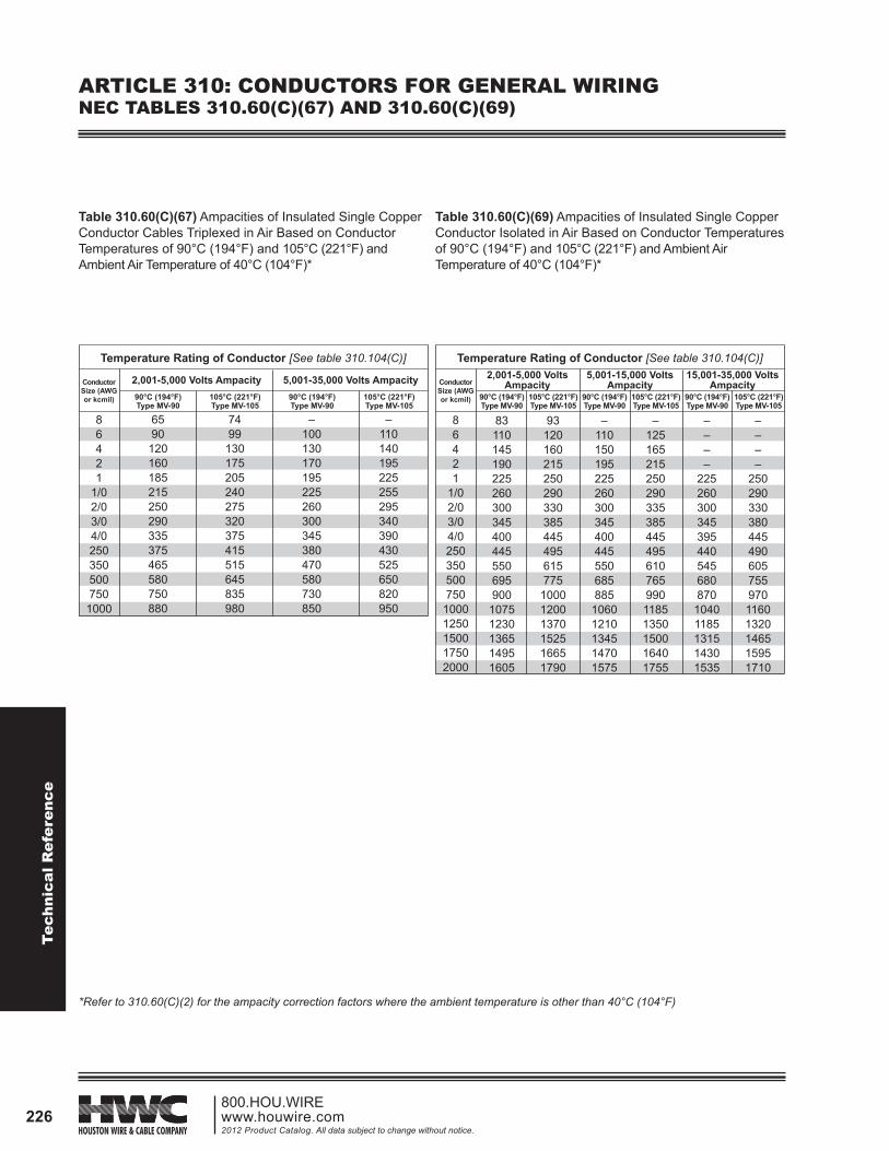
ARTICLE 310: CONDUCTORS FOR GENERAL WIRINGNEC TABLES 310.60(C)(67) AND 310.60(C)(69)
Table 310.60(C)(67) Ampacities of Insulated Single Copper Conductor Cables Triplexed in Air Based on Conductor Temperatures of 90°C (194°F) and 105°C (221°F) and Ambient Air Temperature of 40°C (104°F)*
Table 310.60(C)(69) Ampacities of Insulated Single Copper Conductor Isolated in Air Based on Conductor Temperatures of 90°C (194°F) and 105°C (221°F) and Ambient Air Temperature of 40°C (104°F)*
86421
1/02/03/04/0250350500750
1000
Temperature Rating of Conductor [See table 310.104(C)]
2,001-5,000 Volts Ampacity 5,001-35,000 Volts Ampacity
6590
120160185215250290335375465580750880
7499
130175205240275320375415515645835980
–100130170195225260300345380470580730850
–110140195225255295340390430525650820950
90°C (194°F)Type MV-90
105°C (221°F)Type MV-105
90°C (194°F)Type MV-90
105°C (221°F)Type MV-105
Conductor Size (AWG or kcmil)
86421
1/02/03/04/0250350500750
10001250150017502000
Temperature Rating of Conductor [See table 310.104(C)]2,001-5,000 Volts
Ampacity5,001-15,000 Volts
Ampacity15,001-35,000 Volts
Ampacity
83110145190225260300345400445550695900
10751230136514951605
93120160215250290330385445495615775
100012001370152516651790
–110150195225260300345400445550685885
10601210134514701575
–12516521525029033538544549561076599011851350150016401755
––––
225260300345395440545680870
10401185131514301535
––––
25029033038044549060575597011601320146515951710
90°C (194°F)Type MV-90
105°C (221°F)Type MV-105
90°C (194°F)Type MV-90
105°C (221°F)Type MV-105
90°C (194°F)Type MV-90
105°C (221°F)Type MV-105
Conductor Size (AWG or kcmil)
*Refer to 310.60(C)(2) for the ampacity correction factors where the ambient temperature is other than 40°C (104°F)

Technical Reference
227800.HOU.WIRE
www.houwire.com2012 Product Catalog. All data subject to change without notice.
ARTICLE 310: CONDUCTORS FOR GENERAL WIRINGNEC TABLES 310.60(C)(71), 310.60(C)(73) AND 310.60(C)(75)
Table 310.60(C)(71) Ampacities of an Insulated Three Conductor Copper Cable Isolated in Air Based on Conductor Temperatures of 90°C (194°F) and 105°C (221°F) and Ambient Air Temperature of 40°C (104°F)*
Table 310.60(C)(73) Ampacities of an Insulated Triplexed or Three-Conductor Copper Cables in Isolated Conduit in Air Based on Conductor Temperatures of 90°C (194°F) and 105°C (221°F) and Ambient Air Temperature of 40°C (104°F)*
86421
1/02/03/04/0250350500750
1000
Temperature Rating of Conductor [See table 310.104(C)]
2,001-5,000 Volts Ampacity 5,001-35,000 Volts Ampacity
5979
105140160185215250285320395485615705
6688115154180205240280320355440545685790
–93
120165185215245285325360435535670770
–105135185210240275315360400490600745860
90°C (194°F)Type MV-90
105°C (221°F)Type MV-105
90°C (194°F)Type MV-90
105°C (221°F)Type MV-105
Conductor Size (AWG or kcmil)
Table 310.60(C)(75) Ampacities of an Insulated ThreeConductor Copper Cable Isolated in Air Based on Conductor Temperatures of 90°C (194°F) and 105°C (221°F) and Ambient Air Temperature of 40°C (104°F)*
86421
1/02/03/04/0250350500750
1000
Temperature Rating of Conductor [See table 310.104(C)]
2,001-5,000 Volts Ampacity 5,001-35,000 Volts Ampacity
526991
125140165190220255280350425525590
5877
100135155185210245285315390475585660
–83
105145165195220250290315385470570650
–92
120165185215245280320350430525635725
90°C (194°F)Type MV-90
105°C (221°F)Type MV-105
90°C (194°F)Type MV-90
105°C (221°F)Type MV-105
Conductor Size (AWG or kcmil)
86421
1/02/03/04/0250350500750
1000
Temperature Rating of Conductor [See table 310.104(C)]
2,001-5,000 Volts Ampacity 5,001-35,000 Volts Ampacity
557597
130155180205240280315385475600690
6184110145175200225270305355430530665770
–83110150170195225260295330395480585675
–93
12016519021525529033036540
535655755
90°C (194°F)Type MV-90
105°C (221°F)Type MV-105
90°C (194°F)Type MV-90
105°C (221°F)Type MV-105
Conductor Size (AWG or kcmil)
*Refer to 310.60(C)(2) for the ampacity correction factors where the ambient temperature is other than 40°C (104°F)
Tech
nica
l Ref
eren
ce
228800.HOU.WIREwww.houwire.com2012 Product Catalog. All data subject to change without notice.
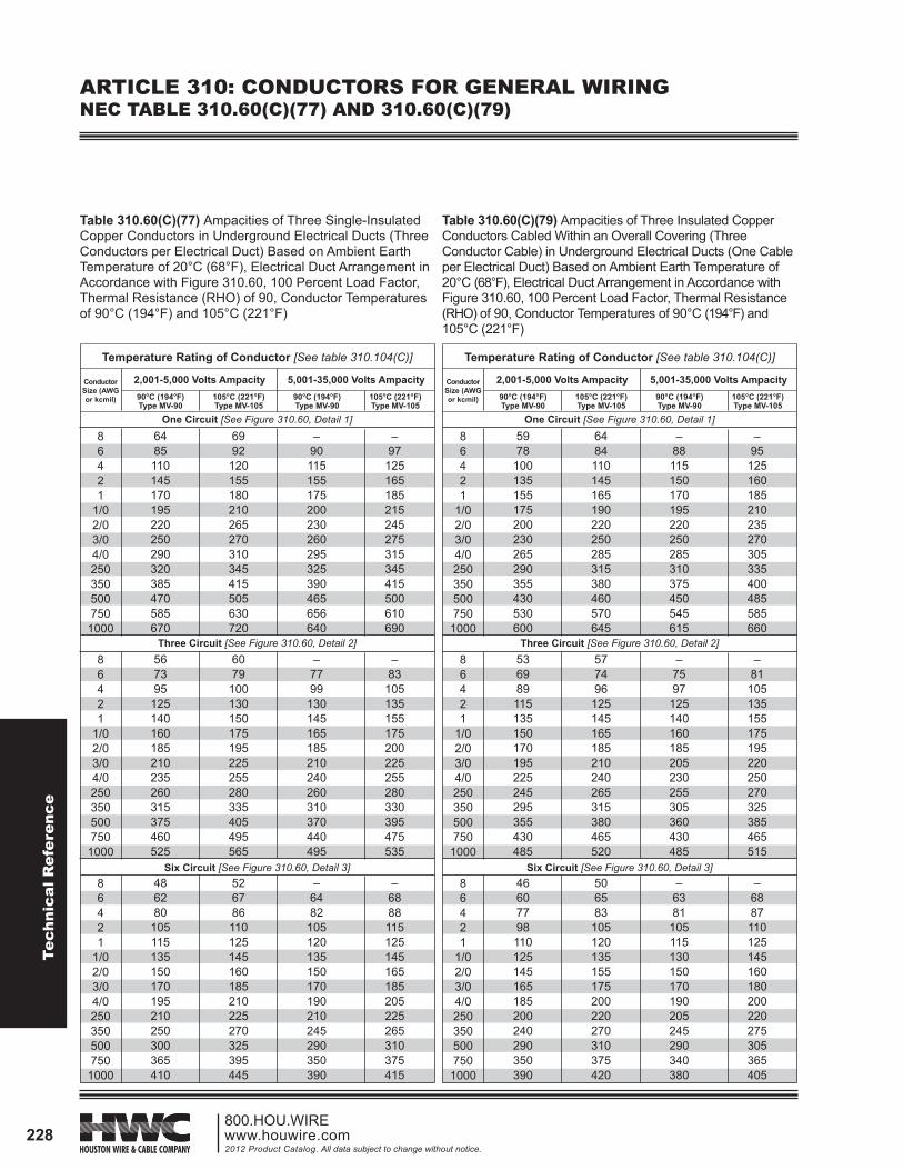
ARTICLE 310: CONDUCTORS FOR GENERAL WIRINGNEC TABLE 310.60(C)(77) AND 310.60(C)(79)
Table 310.60(C)(77) Ampacities of Three Single-Insulated Copper Conductors in Underground Electrical Ducts (Three Conductors per Electrical Duct) Based on Ambient Earth Temperature of 20°C (68°F), Electrical Duct Arrangement in Accordance with Figure 310.60, 100 Percent Load Factor, Thermal Resistance (RHO) of 90, Conductor Temperatures of 90°C (194°F) and 105°C (221°F)
Table 310.60(C)(79) Ampacities of Three Insulated Copper Conductors Cabled Within an Overall Covering (Three Conductor Cable) in Underground Electrical Ducts (One Cable per Electrical Duct) Based on Ambient Earth Temperature of 20°C (68°F), Electrical Duct Arrangement in Accordance with Figure 310.60, 100 Percent Load Factor, Thermal Resistance (RHO) of 90, Conductor Temperatures of 90°C (194°F) and 105°C (221°F)
86421
1/02/03/04/0250350500750
1000
86421
1/02/03/04/0250350500750
1000
86421
1/02/03/04/0250350500750
1000
Temperature Rating of Conductor [See table 310.104(C)]
2,001-5,000 Volts Ampacity 5,001-35,000 Volts Ampacity
6485110145170195220250290320385470585670
6992
120155180210265270310345415505630720
–90115155175200230260295325390465656640
–97
125165185215245275315345415500610690
567395
125140160185210235260315375460525
6079
100130150175195225255280335405495565
–7799
130145165185210240260310370440495
–83
105135155175200225255280330395475535
486280
105115135150170195210250300365410
526786110125145160185210225270325395445
–6482
105120135150170190210245290350390
–6888115125145165185205225265310375415
90°C (194°F)Type MV-90
105°C (221°F)Type MV-105
90°C (194°F)Type MV-90
105°C (221°F)Type MV-105
Conductor Size (AWG or kcmil)
One Circuit [See Figure 310.60, Detail 1]
Three Circuit [See Figure 310.60, Detail 2]
Six Circuit [See Figure 310.60, Detail 3]
86421
1/02/03/04/0250350500750
1000
86421
1/02/03/04/0250350500750
1000
86421
1/02/03/04/0250350500750
1000
Temperature Rating of Conductor [See table 310.104(C)]
2,001-5,000 Volts Ampacity 5,001-35,000 Volts Ampacity
5978
100135155175200230265290355430530600
6484110145165190220250285315380460570645
–88115150170195220250285310375450545615
–95
125160185210235270305335400485585660
536989115135150170195225245295355430485
577496
125145165185210240265315380465520
–7597
125140160185205230255305360430485
–81
105135155175195220250270325385465515
46607798110125145165185200240290350390
506583
105120135155175200220270310375420
–6381
105115130150170190205245290340380
–6887110125145160180200220275305365405
90°C (194°F)Type MV-90
105°C (221°F)Type MV-105
90°C (194°F)Type MV-90
105°C (221°F)Type MV-105
Conductor Size (AWG or kcmil)
One Circuit [See Figure 310.60, Detail 1]
Three Circuit [See Figure 310.60, Detail 2]
Six Circuit [See Figure 310.60, Detail 3]
Technical Reference
229800.HOU.WIRE
www.houwire.com2012 Product Catalog. All data subject to change without notice.
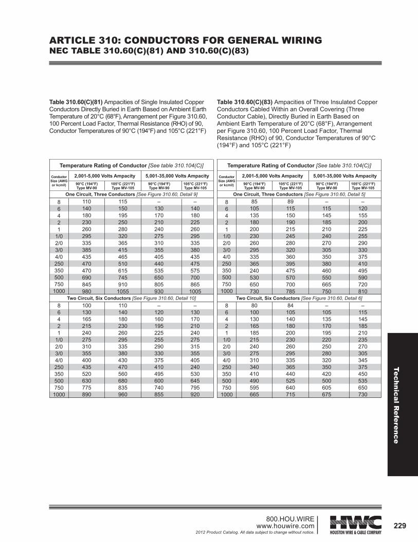
ARTICLE 310: CONDUCTORS FOR GENERAL WIRINGNEC TABLE 310.60(C)(81) AND 310.60(C)(83)
Table 310.60(C)(81) Ampacities of Single Insulated Copper Conductors Directly Buried in Earth Based on Ambient Earth Temperature of 20°C (68°F), Arrangement per Figure 310.60, 100 Percent Load Factor, Thermal Resistance (RHO) of 90, Conductor Temperatures of 90°C (194°F) and 105°C (221°F)
Table 310.60(C)(83) Ampacities of Three Insulated Copper Conductors Cabled Within an Overall Covering (Three Conductor Cable), Directly Buried in Earth Based on Ambient Earth Temperature of 20°C (68°F), Arrangement per Figure 310.60, 100 Percent Load Factor, Thermal Resistance (RHO) of 90, Conductor Temperatures of 90°C (194°F) and 105°C (221°F)
86421
1/02/03/04/0250350500750
1000
86421
1/02/03/04/0250350500750
1000
Temperature Rating of Conductor [See table 310.104(C)]
2,001-5,000 Volts Ampacity 5,001-35,000 Volts Ampacity
110140180230260295335385435470470690845980
115150195250280320365415465510615745910
1055
–130170210240275310355405440535650805930
–140180225260295335380435475575700865
1005
100130165215240275310355400435520630775890
110140180230260295335380430470560680835960
–120160195225255290330375410495600740855
–130170210240275315355405240530645795920
90°C (194°F)Type MV-90
105°C (221°F)Type MV-105
90°C (194°F)Type MV-90
105°C (221°F)Type MV-105
Conductor Size (AWG or kcmil)
One Circuit, Three Conductors [See Figure 310.60, Detail 9]
Two Circuit, Six Conductors [See Figure 310.60, Detail 10]
86421
1/02/03/04/0250350500750
1000
86421
1/02/03/04/0250350500750
1000
Temperature Rating of Conductor [See table 310.104(C)]
2,001-5,000 Volts Ampacity 5,001-35,000 Volts Ampacity
85105135180200230260295335365240530650730
89115150190215245280320360395475570700785
–115145185210240270305350380460550665750
–120155200225255290330375410495590720810
80100130165185215240275310340410490595665
84105140180200230260295335365440525640715
–105135170195220250280320350420500605675
–115145185210235270305345375450535650730
90°C (194°F)Type MV-90
105°C (221°F)Type MV-105
90°C (194°F)Type MV-90
105°C (221°F)Type MV-105
Conductor Size (AWG or kcmil)
One Circuit, Three Conductors [See Figure 310.60, Detail 5]
Two Circuit, Six Conductors [See Figure 310.60, Detail 6]
Tech
nica
l Ref
eren
ce
230800.HOU.WIREwww.houwire.com2012 Product Catalog. All data subject to change without notice.
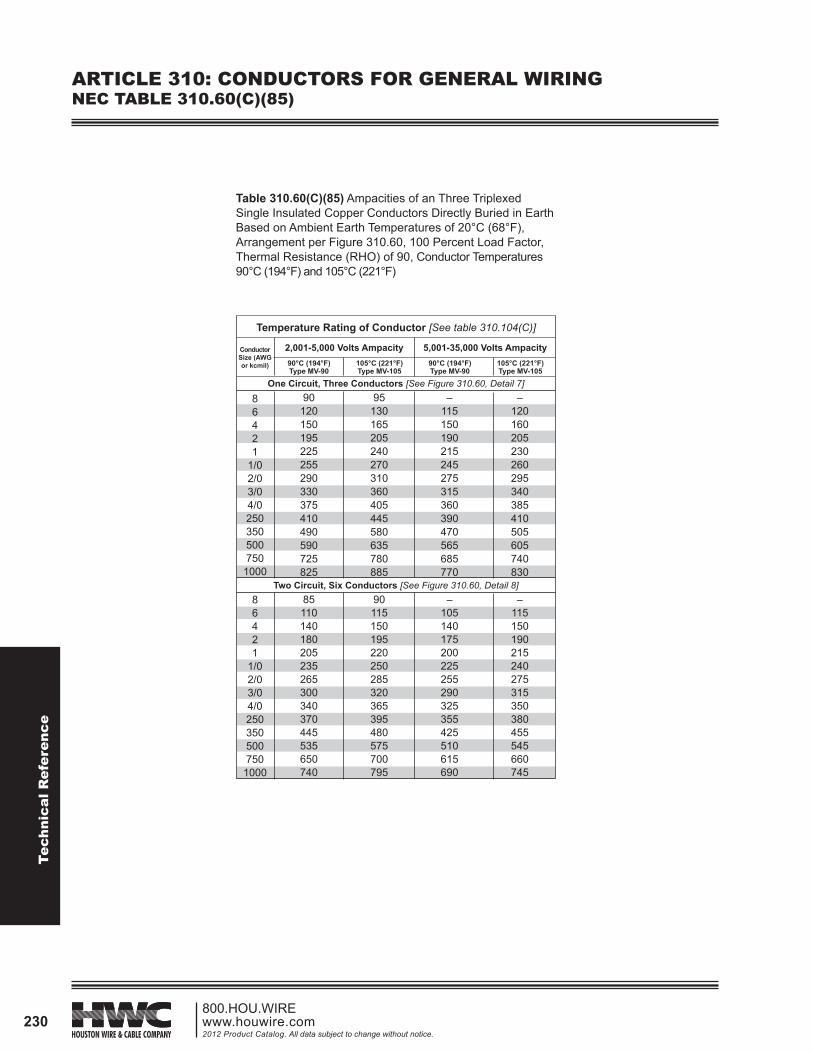
ARTICLE 310: CONDUCTORS FOR GENERAL WIRINGNEC TABLE 310.60(C)(85)
86421
1/02/03/04/0250350500750
1000
86421
1/02/03/04/0250350500750
1000
Temperature Rating of Conductor [See table 310.104(C)]
2,001-5,000 Volts Ampacity 5,001-35,000 Volts Ampacity
90120150195225255290330375410490590725825
95130165205240270310360405445580635780885
–115150190215245275315360390470565685770
–120160205230260295340385410505605740830
85110140180205235265300340370445535650740
90115150195220250285320365395480575700795
–105140175200225255290325355425510615690
–115150190215240275315350380455545660745
90°C (194°F)Type MV-90
105°C (221°F)Type MV-105
90°C (194°F)Type MV-90
105°C (221°F)Type MV-105
Conductor Size (AWG or kcmil)
One Circuit, Three Conductors [See Figure 310.60, Detail 7]
Two Circuit, Six Conductors [See Figure 310.60, Detail 8]
Table 310.60(C)(85) Ampacities of an Three Triplexed Single Insulated Copper Conductors Directly Buried in Earth Based on Ambient Earth Temperatures of 20°C (68°F), Arrangement per Figure 310.60, 100 Percent Load Factor, Thermal Resistance (RHO) of 90, Conductor Temperatures 90°C (194°F) and 105°C (221°F)