artemis Cine Broadcast Manual 1.0 Jan 2018 · !5 1 Overview artemis Cine Broadcast The artemis Cine...
26
artemis Cine Broadcast Date 29. Jan. 2018 USER MANUAL
Transcript of artemis Cine Broadcast Manual 1.0 Jan 2018 · !5 1 Overview artemis Cine Broadcast The artemis Cine...

! 1!
artemis Cine Broadcast
Date 29. Jan. 2018
USER MANUAL

! 2!
Imprint Copyright © 2018 Arnold & Richter Cine Technik GmbH & Co. Betriebs KG. All rights reserved. No parts of this document may be reproduced without prior written consent of Arnold & Richter Cine Technik GmbH & Co. Betriebs KG. Specifications are subject to change without NOTE. Errors, omissions, and modifications excepted. ARRI, ALEXA, AMIRA, LDS and LENS DATA SYSTEM are trademarks or registered trademarks of Arnold & Richter Cine Technik GmbH & Co. Betriebs KG. All other brands or products are trademarks or registered trademarks of their respective holders and should be treated as such. Original version.
For further assistance: Arnold & Richter Cine Technik GmbH & Co. Betriebs KG Türkenstr. 89 80799 München Germany www.arri.comDocument revision history Version Order Code Release Date 1.0 K4.0019237 F06606 29. Jan 2018
Scope This document describes the components and the setup of the artemis Cine Broadcast camera stabilizer systems and its components.
DisclaimerBefore using the products described in this manual, be sure to read and understand all the respective instructions. Otherwise the customer must contact ARRI before using the product. While ARRI endeavors to enhance the quality, reliability and safety of their products, customers agree and acknowledge that the possibility of defects thereof cannot be eliminated entirely. To minimise the risk of damage to property or injury (including death) to persons arising from defects in the products, customers must incorporate sufficient safety measures in their work with the system and heed the stated conditions of use. ARRI or its subsidiaries do not assume any responsibility for losses incurred due to improper handling or configuration of the TRINITY or other system components. ARRI assumes no responsibility for any errors that may appear in this document. The information is subject to change without NOTICE. For product specification changes after this manual was published, refer to the latest published ARRI data sheets or release notes, etc., for the most up-to-date specifications. Not all products and/or types are available in every country. Please check with an ARRI sales representative for availability and additional information. Neither ARRI nor its subsidiaries assume any liability for infringement of patents, copyrights or other intellectual property rights of third parties by or arising from the use of ARRI products or any other liability arising from the use of such products. No license, express, implied or otherwise, is granted under any patents, copyrights or other intellectual property right of ARRI or others. ARRI or its subsidiaries expressly exclude any liability, warranty, demand or other obligation for any claim, representation, cause, action, or whatsoever, express or implied, whether in contract or not, including negligence, or incorporated in terms and conditions, whether by statue, law or otherwise. In no event shall ARRI or its subsidiaries be liable for or have a remedy for recovery of any special, direct, indirect, incidental, or consequential damages, including, but not limited to lost profits, lost savings, lost revenues or economic loss of any kind or for any claim by a third party, downtime, good-will, damage to or replacement of equipment or property, any cost or recovery of any material or goods associated with the assembly or use of our products, or any other damages or injury of the persons and so on or under any other legal theory. In the event that one or all of the foregoing clauses are not allowed by applicable law, the fullest extent permissible clauses by applicable law are validated.
Imprint

! 3! Table of Contents
1 For your safety 4
2 Overview 5
3 Top Stage 6
4 1.8“ Gimbal 9
5 1.8“ Center Post 11
6 Lower Sled 12
7 Battery Management 13
8 Dynamic Balance 16
9 Monitor Bracket 19
10 Docking Bracket 21
11 Service 24
12 Pin Out 26
Table of Contents

! 4!
1 For your Safety
Before use, please ensure that all users comprehensively read, understand, and follow the instructions in this document.
Risk Levels and Alert Symbols
Safety warnings, safety alert symbols, and signal words in these instructions indicate different risk levels:
Danger indicates an imminent hazardous situation which, if not avoided, will result in death or serious injury.
WARNING indicates a potentially hazardous situation which, if not avoided, may result in death or serious injury.
CAUTION indicates a potentially hazardous situation which, if not avoided, may result in minor or moderate injury.
NOTICE
NOTICE explains practices not related to physical injury. No safety alert symbol appears with this signal word.
NOTE
Note provides additional information to clarify or simplify a procedure.
! DANGER
! Warning
! CAUTION
For your Safety

! 5!
1 Overview artemis Cine Broadcast
The artemis Cine Broadcast is the right choice for all professional film and HD cinematography applications. The outstanding modularity and flexibility allows the operator to adapted the artemis Cine Broadcast to any kind production and any kind of task.The connectivity will support any camera and any kind of accessories with power and video.
With the quick-release mechanism, which also functions as a docking ring, you can easily detach the Top Stage and the lower Sled module from the 1.8“ Center Post.
With this feature, you can simply flip the gimbal over for low mode or Super Post operations quickly.
The unique Hot Swap Technology and High Capacity Wiring enable a longer operating time; depending on the type of battery, it can be doubled.
To provide you with the best tool and the best workflow currently available, we added high capacity wiring, three video lines, a digital battery volt meter, D-Tab power, and an USB power out.
The artemis Cine Broadcast can be upgraded any time to the TRINITY.
1.2 Available Upgrades
Gimbal Handle extension K2.0010569Post Extension 8.5in / ø 1.8in K2.0014264Carbon Super Post 1.8in K2.0010491TRINITY upgrade / Gold Mount K0.0012293 TRINITY upgrade / V-Mount K0.0012294
1.1 Features Cine Broadcast • Top Stage and lower Sled
detachable from Center Post • All adjustments are tool free • 8'' Camera dovetail plate
(Pro compatible) • 1.8'' Post, two stages,
with fine trim mechanism • 1.8'' Gimbal (no tool) • 2 x HD SDI, 1 x SD video • Dual Dynamic Balance (patented) • 3 Battery mounts
(Gold or V-Mount battery mounts) • Pivoting battery mount • 12V / 24V, High Capacity wiring • Hot Swap technology • LED battery indicator • USB power out • D-Tap power out • Video power out • Focus power out • Aux power / Tally • External Tally System
Overview
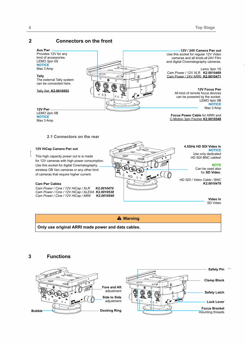
! 6!2 Connectors on the front
2.1 Connectors on the rear
3 Functions
Top Stage
Safety Pin
Clamp Block
Focus Bracket mounting threads
Lock Lever
Safety Latch
Bubble Docking Ring
Side to Side adjustment
Fore and Aft adjustment
12V HiCap Camera Pwr out
This high capacity power out is is made for 12V cameras with high power consumption. Use this socket for digital Cinematography, wireless OB Van cameras or any other kind of cameras that require higher current.Cam Pwr Cables Cam Power / Cine / 12V HiCap / XLR K2.0010470Cam Power / Cine / 12V HiCap / ALEXA K2.0010538 Cam Power / Cine / 12V HiCap / MINI K2.0010540
Video In SD Video
4.5GHz HD SDI Video In NOTICE
Use only dedicated HD SDI BNC cables!
NOTE
Can be used also for SD Video.
HD SDI / Video Cable / BNC
K2.0010476
12V / 24V Camera Pwr out Use this socket for regular 12V Video
cameras and all kinds of 24V Film and digital Cinematography cameras.
Lemo 3pin 1S
Cam Power / 12V XLR K2.0010469 Cam Power / 24V ARRI K2.0010471
Aux Pwr Provides 12V for any kind of accessories.LEMO 3pin 0S NOTICE Max 3 Amp Tally The external Tally system can be connected here.
Tally Set K2.0010553 12V Focus Pwr All kind of remote focus devices can be powered by the socket.
LEMO 4pin 0B NOTICE
Max 3 Amp
Focus Power Cable for ARRI and C-Motion 3pin Fischer K2.0010548
12V Pwr LEMO 2pin 0B NOTICE Max 3 Amp
Only use original ARRI made power and data cables.
! Warning

! 7!
3.1 Quick Lock clamp mechanism
To open the clamp block, pull down the Safety Latch at the end of the Lock Lever first. Swing the Lever fully to the left, by moving it over the engaging positions.
Insert the camera dovetail plate into the mounting platform.
3.1 Fore and aft / Side to Side adjustments
Clockwise rotation of the knurled knob marked Fore / Aft moves the camera dovetail plate forwards. Counter-clockwise rotation moves it backwards. Clockwise rotation of the knurled knob marked Left / Right moves the camera dovetail plate to the right.Counter-clockwise rotation moves it to the left. You can move the camera dovetail plate approximately 30 mm / 1,8'' in both directions.NOTEBefore mounting the camera dovetail plate, you should center the Fore / Aft and Left / Right position. This gives you the same adjustability in all directions later.
NOTICE
The groove at the right side of the camera dovetail plate have to be lined up with the right side of the camera.
Swing back the Lock Lever into the first engaging position. The camera plate can is now already secured and can be still be moved fore and aft, until the camera is positioned in the center of gravity (COG). After determining the final position of the camera dovetail plate, push the quick lock lever fully to the right, until the safety latch engages.
Side to Side
Fore and Aft
Top Stage
Clamp Block
Lock LeverSafety Latch
1
2
Safety Pin
Lens
Groove
Safety Pin
NOTICE
Do not block the safety latch while you push back the lock Lever in its final position.
! 8!
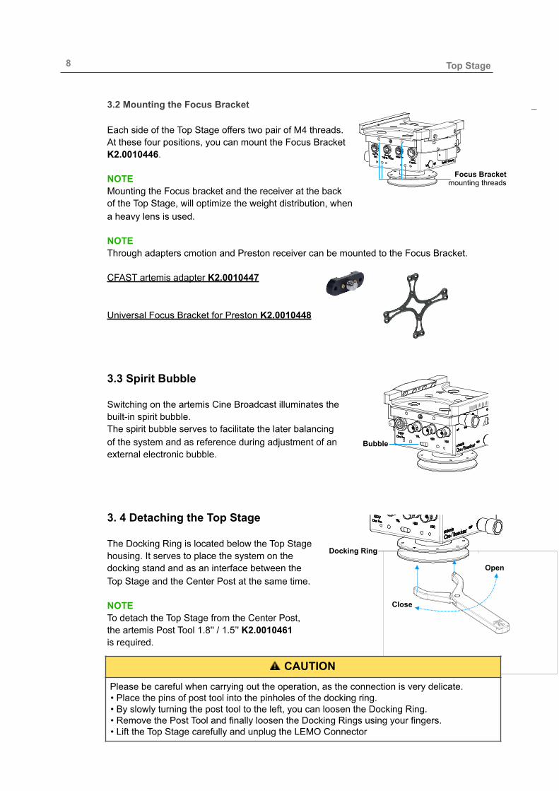
3.2 Mounting the Focus Bracket
Each side of the Top Stage offers two pair of M4 threads. At these four positions, you can mount the Focus Bracket K2.0010446.
NOTEMounting the Focus bracket and the receiver at the back of the Top Stage, will optimize the weight distribution, when a heavy lens is used.
NOTE Through adapters cmotion and Preston receiver can be mounted to the Focus Bracket.
CFAST artemis adapter K2.0010447
Universal Focus Bracket for Preston K2.0010448
3.3 Spirit Bubble
Switching on the artemis Cine Broadcast illuminates the built-in spirit bubble. The spirit bubble serves to facilitate the later balancing of the system and as reference during adjustment of an external electronic bubble.
3. 4 Detaching the Top Stage
The Docking Ring is located below the Top Stage housing. It serves to place the system on the docking stand and as an interface between the Top Stage and the Center Post at the same time.
NOTE To detach the Top Stage from the Center Post, the artemis Post Tool 1.8'' / 1.5’' K2.0010461 is required.
Bubble
Docking Ring
Open
Close
Top Stage
Focus Bracket mounting threads
Please be careful when carrying out the operation, as the connection is very delicate. • Place the pins of post tool into the pinholes of the docking ring. • By slowly turning the post tool to the left, you can loosen the Docking Ring. • Remove the Post Tool and finally loosen the Docking Rings using your fingers. • Lift the Top Stage carefully and unplug the LEMO Connector
! CAUTION

! 9!
4 1.8“ Gimbal
The 1.8'' artemis Gimbal offers high precision, extremely low friction bearings ,a no-tool clamp mechanism and an ergonomic and functional design. The knurled handle diameter is 57 mm / 2.24'', which gives precise torque and more control, even when heavy cameras are used. The Diameter of the curved Gimbal handle (25 mm / 0,984’’) allows to mount zoom device. The yoke shape is optimized for a payload up to 50 kg / 110 lbs.
4.1 Positioning the Gimbal
To modify the position of the 1.8'' Gimbal at the Center Post, you must open the Clamp Lever.
NOTE It is better and more precise to move the Gimbal up and down the Center Post, by turning the gimbal clock and counter clockwise, than moving the Gimbal on the Center Post just by pushing it.
Choose your new position and close the lock lever.
4.2 Gimbal Friction Ring
Another unique feature of the artemis 1.8'' Gimbal is the Friction Ring at the top end of the Gimbal. The adjustable ring ensures that the Gimbal sits and fits perfectly onto the Center Post. This way the Gimbal is guided at both ends, which will ensure that main bearing is 100% positioned and in a line with the Center Post.
Adding a little friction to the Gimbal, will allow a much more precise positioning of the Gimbal. Further on it will ensure that the post cannot slip freely through the Gimbal, in the event of the Gimbal clamp being opened by mistake. NOTEUse the Post Tool to adjust the correct amount of friction.
Clamp Lever
Knurled Gimbal Handle
Curved Gimbal Handle
Gimbal Yoke
Friction Ring
Clamp Lever
Open
Close
Friction Ring
1.8“ Gimbal
Only open the Clamp Lever when the system is parked in the Docking Bracket, or when the system is at a horizontal position.
! CAUTION

! 10!
4.3 Adjusting the Gimbal Friction Ring • Open the Clamp Lever first. • Use the Post Tool and tighten the ring until you
can feel the bushing inside the Gimbal touching the Center Post and a little friction becomes noticeable.
4.4 Upgrade
The 1.8“ Gimbal can be upgraded with the Knurled Handle Extension 1.8’’ K2.0014280.
This extension will add a knurled handle to the top of the 1.8" Gimbal. This way the Gimbal will have knurled handles on both ends. The length of the Knurled Handle Extension is 52 mm / 2“. NOTE Before you can add the Knurled Handle Extension, you need to remove the Top Stage and the Friction Ring of the 1.8“ Gimbal.
Use the Post Tool to open the Docking Ring and the Friction Ring.
Place the Knurled Handle Extension on top of the Gimbal.
NOTEKeep the with Delrin ring inside the Gimbal. Do not remove the ring.NOTE Ensure that no dirt or sand can reach the inside of the Gimbal.
Turn the Knurled Handle Extension just two turns. NOTE Do not over-tighten the Knurled Handle Extension.
Place the gimbal onto the Post, bring it into the needed position and close the Gimbal Clamp.
Bring back the Top Stage onto the post and make sure that the Docking ring is fully tightened.
Tight
Loose
Loose
Tight
1.8“ Gimbal
This is not a Clamp! Do not over tighten the Ring!
! CAUTION
Before removing the Gimbal from the Center Post,you need to loosen the Gimbal Friction Ring!
! CAUTION

! 11!
5 1.8“ Center Post
5.1 Extending the Center Post
The Post can be extended from 43 cm to 72 cm (16.9’’- 28.3’’) Lift and open the clamp Lever, then pull out the inner post slowly.
NOTE To extend the inner post fully, you need to open the Gimbal clamp Lever too.
5.3 Available Upgrades
Post Extension 8.5'' / ø 1.8'' K2.0014264 In addition to the standard post, you can add the modular Center Post extension. This is a fast and simple to use plug and play solution that allowing you to lengthen the Center Post by 216 mm / 8.5’’.
The two stage artemis 1.8’’ carbon Post offers a no-tool post clamp and a guided 1.5’’ inner telescopic post.
Therefore, monitor brackets and existing accessories based on a 1.5'' diameter can be used on with the 1.8'' post.
Only the artemis 1.8’’ Post offers the unique no-tool Fine Trim mechanism for a precise length adjustment of the 1.5’’ inner telescopic post. Finding the perfect Drop Down time is more than easy with the Fine Trim mechanism. There is no need any more to open the post or gimbal clamp to readjust the drop down after changing a filter or a lens.
Fine Trim
Clamp Lever
5.2 Fine Trim Mechanism This Fine Trim allows you to adjust the length of the inner post and the resulting Drop Down time is extremely accurate.
The Fine Trim allows 22mm (0,86’’) overall movement in both directions.
NOTE Adjust the Fine Trim halfway before balancing. Using This method you can add more drop down if needed, or you can get the rig very quickly into a „Dirty Low Mode“ balance.
Clamp Lever
Fine Trim
Docking Ring
1.5’’ Inner Post
1.8’’ Outer Post
Clamp force adjustment screw
1.8“ Center Post
! 12!
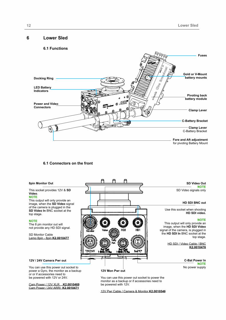
6 Lower Sled
6.1 Functions
6.1 Connectors on the front
Lower Sled
Gold or V-Mount battery mounts
Clamp Lever
C-Battery Bracket
Fore and Aft adjustment for pivoting Battery Mount
Pivoting back battery module
Clamp Lever C-Battery Bracket
Fuses
LED Battery Indicators
Power and Video Connectors
Docking Ring
8pin Monitor Out This socket provides 12V & SD Video. NOTE This output will only provide an image, when the SD Video signal of the camera is plugged in the SD Video In BNC socket at the top stage.
NOTE The 8 pin monitor out will not provide any HD SDI signal.
SD Monitor Cable Lemo 8pin - 8pin K2.0010477
HD SDI BNC out
Use this socket when shooting HD SDI video.
NOTE This output will only provide an
image, when the HD SDI Video signal of the camera, is plugged in
the HD SDI In BNC socket at the top stage.
HD SDI / Video Cable / BNC K2.0010476
12V / 24V Camera Pwr out
You can use this power out socket to power a Gyro, the monitor as a backup or or if accessories need to be powered with 12V or 24V.
Cam Power / 12V XLR K2.0010469 Cam Power / 24V ARRI K2.0010471
12V Mon Pwr out
You can use this power out socket to power the monitor as a backup or if accessories need to be powered with 12V.12V Pwr Cable / Camera & Monitor K2.0010546
SD Video Out NOTE
SD Video signals only
C-Bat Power In NOTE
No power supply

! 13! 6.2 Additional Connectors and Functions
7 Battery Management / Hot Swap and 24V
The artemis Cine Broadcast offers the most versatile battery management. Position and the function of the batteries can be selected freely. To get the best dynamic balance you can place the batteries where the counterweight is needed and then you decide how to use the battery. The Cine Broadcast can be powered with one, two or three batteries. When two batteries are used, the Cine Broadcast offers Hot Swap or 24V camera power.
7.1 First Variant Running the system with only ONE battery You can run the complete system, camera and monitor with only one battery.
1.1 When only one battery is mounted in the A-Batt. battery mount The switches must be configured as shown here:
1.1 To use only one battery in the B-Batt. battery mount The switches must be configured as shown here:
2 Batt A-B Hot Swap
3 Batt A-C 24 Volt
2 Batt A-B Hot Swap
3 Batt A-C 24 Volt
Lower Sled / Battery Management
B-Batt.
A-Batt.
C-Batt.
USB
D-Tab
D-Tab
Fuse A-Batt.
Fuse B-Batt.
Fuse C-Batt.Battery Management
Hot Swap and 24V
Fuses
D-Tab

! 14!
1.3 To use only one battery in the C-Batt. battery mountThe switches must be configured as shown here:
7.2 Second VariantRunning the system with TWO batteries
You can run the complete system, camera and monitor with two batteries using the Hot Swap. In this mode, you can change one battery after the other, without losing the camera, monitor and Transmitters or recorders. To operate the system with 12V and Hot Swap, you need minimum two batteries and the switcher Hot Swap / 24V have to be in the always in the Hot Swap position.
2.1 To use two batteries in the A-Batt. and B-Batt. position The switches must be configured as shown here:
2.2 To use two batteries in the A-Batt. and B-Batt. position The switches must be configured as shown here:
7.3 Third VariantRunning the system with THREE batteries
In this mode, you can run the camera, focus remote, transmitters or recorders with twobatteries using the entire Hot Swap performance, while the monitor and other accessories will run on its own battery.
3.1 To power the camera, focus remote, transmitters or recorders with two batteries, you have to place two batteries in the A-Batt. and B-Batt. battery mounts.
To power monitor and other accessories with its own battery, the third battery have to be placed in the C-Batt. battery mount The switches must be configured as shown here:
3.2 You can also use this combination. Now the Monitor will be powered by the B-Battery.
1
2 Batt A-B Hot Swap
3 Batt A-C 24 Volt
2 Batt A-B Hot Swap
3 Batt A-C 24 Volt
2 Batt A-B Hot Swap
3 Batt A-C 24 Volt
2 Batt A-B Hot Swap
3 Batt A-C 24 Volt
2 Batt A-B Hot Swap
3 Batt A-C 24 Volt
Battery Management

! 15!
7.4 Forth Variant 24 Volt for Camera and 12V for monitor and system
4.1 Running the system in 24V with only 2 batteries:
You can run the entire system, camera and monitor with only two batteries. To power the camera with 24V, you have to have two similar batteries in the A-Batt. and the B-Batt. battery mounts.
The switches must be configured as shown here:
NOTE In this setup, the monitor will be powered with 12Volt by the B-Battery. Only the camera will be powered with 24 Volt, all other 12 Volt outlets will still provide 12 Volt.
4.2 Running the system in 24V with 3 batteries:
You can run the entire system, camera and monitor using three batteries. To power the camera with 24V, you have to have two batteries in the A-Batt. and the B-Batt. battery mounts. To power the monitor from its own battery, place the third battery in the C-Batt. battery mount.
The switches must be configured as shown here:
NOTE In this setup, the monitor will be powered with 12Volt by the C-Battery. Only the camera will be powered with 24 Volt, all other 12 Volt outlets will still provide 12 Volt. 7.5 Volt Meter
Two LED Volt meters are located at the top of the Cine Broadcast Sled.NOTEDepending how many batteries are in use, the Volt meter will show the Battery power of the single battery or the power of two hot swapped batteries.If only two batteries are used, each battery will have its own LED display. If three batteries are in use, then the hot swapped, or the two batteries which provides 24 Volt, will be displayed on only one of the LED displays. The other LED display will now show the third remaining battery.
2 Batt A-B Hot Swap
3 Batt A-C 24 Volt
2 Batt A-B Hot Swap
3 Batt A-C 24 Volt
Battery Management

! 16!8 Pivoting Battery Mount Module
In 2001, artemis presented the first pivoting Battery Mount Module consisting of two battery mounts, fuses and electronics in the market. This technology is part of the patented Dual Dynamic Balance and allows you to align the center of gravity of the batteries with the center of gravity of the monitor. This leads to a better and homogeneous overall balance in the lower sled, which will result in a better Dynamic Balance.Due to the principle of Lever, light batteries will appear heavier, if you pivot the battery mount module downwards, because their distance to the system has increased. The counterweight increases, but not the system‘s total weight. To pivot the batteries effects the relation between lens and battery. The longer or heavier the lens gets, the flatter you can choose the angle of the battery mount module.
8.1 Perfect Dynamic Balance
The extended range of the patented ''Dual Dynamic Balance'' of the artemis Cine Broadcast systems, in combination with the artemis Monitor Bracket allows mounting the batteries and the monitor at independently adjustable positions.
This unique feature of the artemis Cine Broadcast offers the following benefits: • There is always enough counterweight available • The position of the counter weight (monitor and the batteries) can be adjusted easily • The monitor and the batteries can be moved independently from each other • The batteries can be moved and placed independently of each other,
when balancing the system. • The dimensions and the weight distribution of the camera setup at the top can be
“cloned” easily by moving the monitor and battery to the correct position.This flexible adjustments guarantees that you have always enough battery power on board, and versatile positioning of the batteries for a perfect dynamic balance.
8.2 Dual Dynamic Balance
One key aspect of the Dual Dynamic Balance is the third battery, the so-called C-Batt. The C-Bat is mounted on rods right below the Lower Sled and allows sliding the C-Batt fore and aft.
Dynamic Balance
! 17!
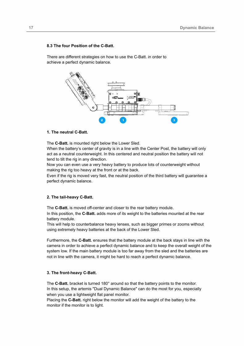
8.3 The four Position of the C-Batt. There are different strategies on how to use the C-Batt. in order to achieve a perfect dynamic balance.
1. The neutral C-Batt.
The C-Batt. is mounted right below the Lower Sled. When the battery‘s center of gravity is in a line with the Center Post, the battery will only act as a neutral counterweight. In this centered and neutral position the battery will not tend to tilt the rig in any direction. Now you can even use a very heavy battery to produce lots of counterweight without making the rig too heavy at the front or at the back. Even if the rig is moved very fast, the neutral position of the third battery will guarantee a perfect dynamic balance.2. The tail-heavy C-Batt. The C-Batt. is moved off-center and closer to the rear battery module. In this position, the C-Batt. adds more of its weight to the batteries mounted at the rear battery module. This will help to counterbalance heavy lenses, such as bigger primes or zooms without using extremely heavy batteries at the back of the Lower Sled. Furthermore, the C-Batt. ensures that the battery module at the back stays in line with the camera in order to achieve a perfect dynamic balance and to keep the overall weight of the system low. If the main battery module is too far away from the sled and the batteries are not in line with the camera, it might be hard to reach a perfect dynamic balance.
3. The front-heavy C-Batt. The C-Batt. bracket is turned 180° around so that the battery points to the monitor. In this setup, the artemis "Dual Dynamic Balance" can do the most for you, especially when you use a lightweight flat panel monitor. Placing the C-Batt. right below the monitor will add the weight of the battery to the monitor if the monitor is to light.
312
Dynamic Balance

! 18!
4. Low Mode The Dual Dynamic Balance improves low mode operations extremely and supports fast and easy setup procedures.In Low-Mode the monitor must be moved to a position where the operator can see it better. But often, the best position for the monitor is not the perfect position for the balance. The artemis Dual Dynamic Balance solves this problem.When the C-Batt. points forward and an appropriate battery is used, this battery in this special position will simulate the monitor‘s weight that will not bethere anymore when the rig is set up for low mode. If you also pivot the battery module upwards, you will get the strongest counterweight effect of the batteries. Now the position of the monitor is absolute free, because the C-Batt. will do its job and act as counterweight. The artemis Dual Dynamic Balance allows to position all three batteries even in low mode in a way that is fully supporting the concept of balancing in a square. As a result, you get perfect control of the framing because you can choose your preferred monitor position and the perfectly balanced rig gives youa completely free hand.
8.4 Perfect Dynamic Balance
The extended range of the patented Dual Dynamic Balance of the artemis Cine Broadcast allows mounting the batteries and the monitor at independently adjustable positions. This unique feature of the artemis offers the following benefits: • There is always enough counterweight available• The position of the counter weight (monitor and the batteries) can be adjusted absolutely free and easily • The monitor and the batteries can be moved independently of each other • The batteries can be moved and placed independently of each other, when balancing the system.
NOTE This flexible adjustments guarantee that you have always enough battery power on board and versatile positioning of the batteries for a perfect Dynamic Balance.
Dynamic Balance
Using the ACT2 Monitor Bracket in Low-Mode:
The way the monitor is mounted onto the ACT2 Monitor Bracket, works like a „quick release“ mechanism.So changing the bracket into low-mode operation is quick and simple.
Keep the rig in high-mode while doing this operation.
Open the lock knobs fully.
Flip over the u-shaped monitor bracket.
Note:Make sure that both of the lock knobsare tightened firmly.
Now you can continue to prepare thecomplete rig for low-mode operation.
As shown on the photo, you can keep the post clamp at the same position as used for high-mode before.This will save time later when will go back into high-mode.
To bring the monitor lower, tilt down the complete bracket and extend it fully.
Note:
Make sure that the clamp levers of thepivoting joint and of the rod clampare tightened firmly.
Specifications are subject to change without notice www.artemis-hd.com 14

! 19! 9 Monitor Bracket To achieve perfect balance, the monitor should be in perfect balance. The design of the artemis Monitor Bracket is based on the idea to mount the monitor at its center of gravity, the so-called COG. When the monitor is mounted neutral at its COG, changing the viewing angle of the monitor will not interfere with the balance of the rig anymore.
9.1 Pivoting Joints Because the artemis monitor bracket has 3 pivoting joints, there are numerous anglesand positions that are possible. You will definitely find the best position and angle, to achieve a perfect dynamic balance and the right viewing angle to suit the setup of your rig and your style of operating.
9.2 The three pivoting joints:
The first pivoting joint is the one at both side of the monitor housing. The two side brackets mounted to the monitor housing moves the COG of the monitor right into the joint. NOTE This joint has a pre-adjusted friction.
The second pivoting joint is right at the base of quick release mechanism, at the base of the Monitor Bracket. Here it is possible to change the angle of the yoke and the monitor at the same time.
The quick release mechanism allows you to flip over the monitor for Low-Mode in seconds. Because it is so easy to detach the monitor from the Monitor Bracket, you can store the monitor in case for transportation. The third pivoting joint is the rosette at the post clamp. This feature allows you to get the best counterweight effect out of the monitor and best viewing position for the operator.
9.3 Changing the Tilt Angle of the Monitor
To change the angle of the monitor, just tilt the monitor itself fore and aft, until the monitor is in the right position.
Monitor Bracket
123
Do not open the pivoting clam screws!
! CAUTION

! 20!
9.4 Changing the angle of the u-shaped Monitor Mount
Open the lock knobs to a maximum of 2 thread turns to the left. Move the monitor yoke into the right position and tighten both lock knobs. 9.5 Changing the angle at the Post Clamp
To change the overall angle of the monitor bracket, slowly open the clamp lever of the pivoting joint about 2 thread turns. This will give you enough clearance between the two steel rosettes to tilt the bracket up and down, until it reached the requested angle.
9.6 Extending the length of the Monitor Bracket Open the lock lever at the side of the bridge and move the rods in or out, until the bracket reached the requested position. 9.7 Using the artemis Monitor Bracket in Low-Mode
The way the monitor is mounted onto the artemis Monitor Bracket, works like a quick release mechanism. So changing the bracket into Low-Mode operation is quick and simple. Keep the rig in high-mode while doing this operation. Open the lock knobs fully. Flip over the u-shaped monitor bracket. NOTE Make sure that both of the lock knobs are tightened firmly. Now you can continue to prepare the complete rig for Low-Mode operation. As shown on the photo, you can keep the post clamp at the same position as used for high-mode before. This will save time later when will go back into high-mode. To bring the monitor lower, tilt down the complete bracket and extend it fully.
NOTE Make sure that the clamp levers of the pivoting joint and of the rod clamp are tightened firmly.
NOTE The artemis monitor bracket allows you to mount a second monitor mount.It is possible to mount a Transvideo Starlite monitor if required.
Using the ACT2 Monitor Bracket in Low-Mode:
The way the monitor is mounted onto the ACT2 Monitor Bracket, works like a „quick release“ mechanism.So changing the bracket into low-mode operation is quick and simple.
Keep the rig in high-mode while doing this operation.
Open the lock knobs fully.
Flip over the u-shaped monitor bracket.
Note:Make sure that both of the lock knobsare tightened firmly.
Now you can continue to prepare thecomplete rig for low-mode operation.
As shown on the photo, you can keep the post clamp at the same position as used for high-mode before.This will save time later when will go back into high-mode.
To bring the monitor lower, tilt down the complete bracket and extend it fully.
Note:
Make sure that the clamp levers of thepivoting joint and of the rod clampare tightened firmly.
Specifications are subject to change without notice www.artemis-hd.com 14
Monitor Bracket

! 21!
10 Docking Bracket
10.1 Stand Assembly
The stand joint is designed for stands with ø 15,9 mm spigot.Put the docking bracket on the stand pin and tighten the lateral stand lock screw accurately.
10.2 Moving the Balance Rod
To move the Balance Rod fore and aft,or to bring Balance Rod into the right position, or to lock the Balance Rod finally, the blue Rod Bar Clamp Lever has to be in the correct position.10.3 The three positions of the Tool Bar
There are three positions where the Balance Rod is locked and two positions where the Balance Rod can be moved freely.Just turn the Tool Bar to lock or to move the Balance Rod.
Balance Pin
Balance Pin
Balance Rod
Rod Bar Clamp Lever
Docking Bar (Delrin)
Arm Pin
Stand Joint
Spigot Clamp Screw
Arm Pin
Docking Bracket
Locked
LockedLocked
Unlocked Unlocked45°
45°
• Use only appropriate steel stands, such as a C-Stand or Low Boy and prevent the stand from tipping by using a sandbag.
• Make sure the stand is flush with the surface.
• Make sure that that the spigot clamp screw is fully tightened.
! CAUTION
Make sure you lock the Balance Rod after moving it into the correct position.
! CAUTION

! 22!
10.4 The different positions of the Balance Rod 10.5 Park Position
To park the rig, the Balance Rod has to be fully moved to the back.
10.6 Balance Position
There is no need to turn the docking bracket 180° around to to balance the system. Just open the Lock Lever, pull the rod forward in the position indicated, lock the balance rod and place the Gimbal on the top of the Balance Pin.
10.7 Spin Position
To do the so called spin test, you can user the Balance Pin you are already on, or you turn the Docking Bracket 180° and use the Balance Pin on the others side.
NOTE Please make sure that you do not pull out the Balance Rod any longer that is required. Also make sure your rig is still inside the „foot print“ of the stand!
10.8 Transport Position
For transport, it is the best to centre the Balance Rod as shown. Also move the locking lever to the center position, this will keep the bracket as compact as possible.
Docking Bracket
If you ignore this, the balance pin might cause damage to the top stage and side to side adjustment knob.
! CAUTION
! 23!
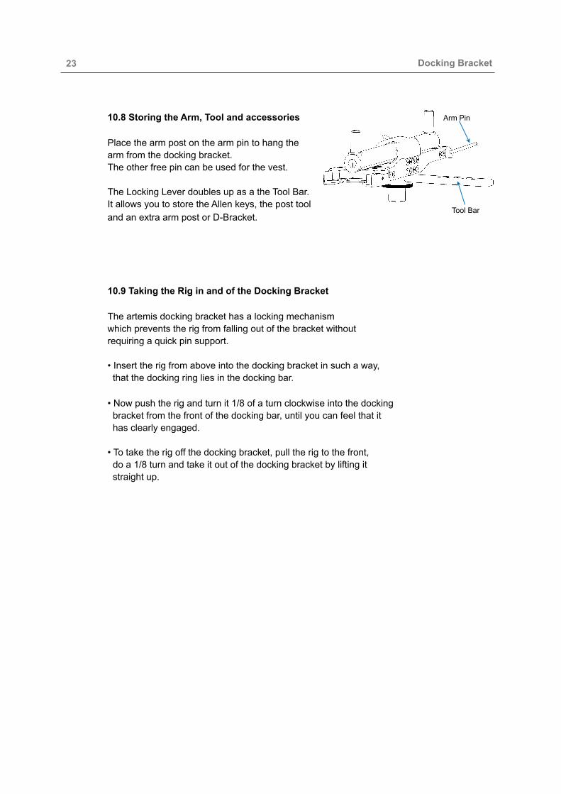
10.8 Storing the Arm, Tool and accessories Place the arm post on the arm pin to hang the arm from the docking bracket.The other free pin can be used for the vest.
The Locking Lever doubles up as a the Tool Bar. It allows you to store the Allen keys, the post tool and an extra arm post or D-Bracket.10.9 Taking the Rig in and of the Docking Bracket
The artemis docking bracket has a locking mechanism which prevents the rig from falling out of the bracket without requiring a quick pin support. • Insert the rig from above into the docking bracket in such a way, that the docking ring lies in the docking bar.
• Now push the rig and turn it 1/8 of a turn clockwise into the docking bracket from the front of the docking bar, until you can feel that it has clearly engaged.
• To take the rig off the docking bracket, pull the rig to the front, do a 1/8 turn and take it out of the docking bracket by lifting it straight up.
Docking Bracket
Arm Pin
Tool Bar

! 24!
11 Service
11.1 Adjusting the clamp force of the Clamp Block
If the clamping force becomes too weak, readjusting is needed. Use the 1,5 mm Hex key. The adjustment screw is located inside the clamp block. Just a 1/8 or 1/4 of turn, is enough to increase the clamp force.
11.2 Adjusting the artemis Top Stage
If vertical vibrations occur in the upper level of the Top Stage, in between the dovetail plate carrier and the frame below, you can readjust yourself the Top Stage to eliminate these vibrations.
On both side of the Top Stage, you will find two little screws right at the edge of this level, which allows you to adjust the „gap“ in between the moving parts.
Please use the 1.5 mm hex key and start to tighten the indicated screws slowly and carefully.
To reach the adjustment screws on the other side, turn the fore and aft knob so that, you can reach the adjustment screws behind the clamp block through the two indicated holes.
If the vertical vibrations are located in the Side to Side mechanism, you need to tighten carefully the indicated screws at the front of the Top Stage.
NOTICE If you still experience vibrations, then please contact the ARRI service in your regionhttps://www.arri.com/support/technical_service/camera_systems/ and arrange to send the Top Stage in for a service.
Service
Clamp Block
Adjustment Screw
Dovetail Plate Carrier
Frame
Adjustment Screws
Adjustment Screws
Adjustment Screws
Do not over tighten!
! CAUTION
Do not over tighten!
! CAUTION
Do not over tighten!
! CAUTION
Do not over tighten!
! CAUTION

! 25!
11.3 Gimbal Clamp Force
If the clamp force of the Gimbal clamp gets weak, the clamp mechanisms need to be readjusted.
NOTICE Open the Clamp Lever first.The clamp force can be readjusted by turning the silver nut by a 1/8 or 1/4 turn to the right.
11.4 Center Post Clamp Force
If the clamp force of the Post clamp gets weak, the clamp mechanisms needs to be readjusted.
NOTE Open the Clamp Lever first.The clamp force can be readjusted by turning the silver nut by a 1/8 or 1/4 turn to the right.
11.5 Docking Bracket
Adjusting the clamp force of the Docking Bar. To re-adjust the clamping strength of the docking bar tighten one of the clamp force screws by 1/2 of a turn. Dock the rig to see you have achieved the required clamp force.
Service
Clamp Lever
Clamp Force
Adjustment Screw
Clamp Lever
Clamp Force Adjustment Screw
Adjustment
Screw
Yoke Cover
Do not over tighten the leveling screw! As this will result in the clamp force becoming too strong and the carbon post may get damaged.
! CAUTION
Do not remove the yoke covers at the side of the Gimbal yoke! Do not try to adjust the Gimbal screws below the covers yourself. This can only be done by the ARRI Service.
! DANGER
Do not over tighten the leveling screw! As this will result in the clamp force becoming too strong and the carbon post may get damaged.
! CAUTION
The effect of over tightening will mean that you will not be able to dock the rig.
! CAUTION
Pin Out

! 26! 12 Pin Out
12
3
12V -
Lemo 1S 303Counter-Clockwise
Camera Power 12V / 24V
12V +
24V +
1
2 3
412V +
12V -
12V HiCap Camera Power
Lemo 1B.304Counter-Clockwise
12
3
LEMO 0S 303
Aux Power 12V / Tally
12V - 12V +
Tally
Counter-Clockwise
12
3 4
FFA 0S 304
Focus Power Plug 12V
Counter-Clockwise
12V -
LEMO 0B 302
1
22V1 +
12V-12V Power
Counter-ClockwiseLemo FGG 1B 308
1
2
34 5
6
78
12V -12V +
Video +Video -
SD Monitor Plug - 8pin / 8pin
12V +